Embed Size (px)
Citation preview


F235-8-17R1.00 F-PRO User Manual
F-PRO
Non-Directional Multifunction Protection Relay
User Manual
Variant – F-PRO 295 Version 1.1 Rev 0
F295-03-17R1.10 F-PRO User Manual

i F-PRO User Manual F295-03-17R1.10
1 Preface
Information in this document is subject to change without notice. © 2015 Easun Reyrolle Ltd. All rights reserved. Reproduction in any manner whatsoever without the written permission of Easun Reyrolle Ltd. is strictly forbidden.This manual is part of a complete set of product documentation that includes detailed drawings and operation. Users should evaluate the information in the context of the complete set of product documentation and their particular applications. ERL assumes no liability for any incidental, indirect or consequential damages arising from the use of this documentation.
While all information presented is believed to be reliable and in accordance with accepted engineering practices, ERL makes no warranties as to the completeness of the information. All trademarks used in association with B-PRO, F-PRO, iTMU, L-PRO, ProLogic,S-PRO, T-PRO, TESLA, TESLA Control Panel, Relay Control Panel, RecordGraph and RecordBase are trademarks of ERL PhasePower Technologies Ltd. Windows® is a registered trademark of the Microsoft Corporation. Modbus® is a registered trademark of Modicon.
2 Contact Information
Easun Reyrolle Ltd
Website: www.easunreyrolle.com
Email: [email protected]
Technical Support
Email: [email protected]
Tel: +91-4344-401600/01/02
ERLPhase Power Technologies Ltd
Website: www.erlphase.com
Email: [email protected]
Technical Support
Email: [email protected]
Tel: 1-204-477-0591
F295-03-17R1.10 F-PRO User Manual ii
3 Using This Guide
This User Manual describes the installation and operation of the F-PRO Multifunction Protection Relay. It is intended to support the first time user and clarify the details of the equipment. The manual uses a number of conventions to denote special information:
Example Describes
Start>Settings>Control Panel Choose the Control Panel submenu in the Set - tings submenu on the Start menu.
Right-click Click the right mouse butt on.
Recordings Menu items and tabs are shown in italics.
Service User input or keystrokes are shown in bold.
Text boxes similar to this one Relate important notes and informa tion.
…. Indicates more screens.
Indicates further drop-down menu, click to display list.
Indicates a warning.

iii F-PRO User Manual F295-03-17R1.10
4 Table of Contents
1 Preface…………………………………………………………………….i
2 Contact Information……………………………………………………..i
3 Using this Guide…………………………………………………………ii
4 Table of Contents……………………………………………………….iii
5 Acronyms………………………………………………………………...v
6 Version Compatibility………………………………………………….vi
7 PC System Requirements and Software Installation……………...…vii
8 Overview………………………………….…………………………………..8-1
Introduction…………………………….……….……..…….…………..8-1
Front View…………………………………………….....……..…..…….8-3
Rear View………………………………………………………………...8-4
Model Options/Ordering………………………………………………..8-5
9 Setup and Communication……………………………………………….9-1
Introduction……………………………………………………………..9-1
Power Supply……….……………………………...……………………9-1
IRIG-B Time Input………………………………………………...……9-2
Communicating with Relay Intelligent Electronic Devices (IED)...…….9-3
USB Link………………………………………………………………..9-3
Network Link……………………………………………………………9-7
Accessing the Relay’s SCADA Services………………………………..9-7
Communication Port Details……………………………………………9-9
10 Using the IED (Getting Started)…………………………………….10-1
Introduction……………………………………………………………10-1
Interfacing with the Relay……………………………………………..10-1
Front Panel Display……………………………………………………10-1
Relay Control Panel…………………………………………………...10-21
11 Protection Functions Applications and Specifications……………11-1
Protection and Recording Functions………………………………….11-1
Recording Functions…………………………………………………11-25
Logging Functions……………………………………………………11-27

F295-03-17R1.10 F-PRO User Manual iv
12 Data Communication……………………………………………..………12-1
Introduction………………………………………………..…………./12-1
SCADA Protocol…………………………………………..…………..12-1
IEC 61850 Communication.………………………………………….12-3
13 Offliner Settings Software…………………………………………........13-1
Introduction…………………………………………………..……….13-1
Offliner Features……………………………………………………....13-2
Offliner Keyboard Shortcuts………………………………………….13-4
Handling Backward Compatibility…………………………………....13-5
Record Base View Software…………………………………………..13-7
Main Branches from the Tree View……………………………..…….13-8
Settings from a Record…………………………………………...….13-26
14 Installation…………………………………………….……….…………14-1
Introduction………………………………………………………..….14-1
Physical Mounting………………………………………………….…14-1
AC and DC Wiring………………………………………………….....14-1
Communication Wiring…………………………………………....….14-1
Appendix A IED Specifications…………….………………...…..…...A-1
Appendix B IED Settings and Ranges…………………………….…....B-1
Appendix C CT Requirements………………………………..………..C-1
Appendix D Event Messages…………………………………………...D-1
Appendix E Modbus RTU Communication Protocol………….…….....E-1
Appendix F IEC 103 Device Profile………………………………..…...F-1
Appendix G Mechanical Drawings…………………………………….G-1
Appendix H AC Schematic Drawings……………………………...….H-1
Appendix I DC Schematic Drawing……………………………………I-1
Appendix J Function Diagram…………………………………………J-1
Appendix K F-PRO Setting Example…………………………………K-1 Appendix L IEC 61850 Implementation……………………………..L-1 Data Mapping Specifications………………………………………… L-1

v F-PRO User Manual F295-03-17R1.10
5 Acronyms
ASG - Active Setting Group CID - file extension (.CID) for Configured IED Description CT - Current Transformer DCE - Data Communication Equipment DIB - Digital Input Board DIGIO - Digital Input/Output Board DSP - Digital signal processor DTE - Data Terminal Equipment FOCB - F-PRO Output Contact Board GPS - Global Positioning System HMI - Human Machine Interface ICD - file extension (.ICD) for IED Capability Description IEC - International Electrotechnical Commission IED - Intelligent Electronic Device IP - Internet Protocol (IP) address IRIG-B - Inter-Range Instrumentation Group time codes LED - Light-emitting Diode LCD - Liquid Crystal Display LHS - Left Hand Side MPB - Main Processor Board MPC - Micro Processor PLC - Programmable Logic Controller RHS - Right Hand Side RTOS - Real Time Operating System RTU - Remote Terminal Unit SCADA - Supervisory Control And Data Acquisition SG - Setting Group TCP - Transmission Control Protocol TUI - Terminal User Interface UDP - User Datagram Protocol UI - User Interface VI - Virtual Input

F295-03-17R1.10 F-PRO User Manual vi
6 Version compatibility
This chart indicates the versions of Offliner Settings, Record Base View and the User Manual which are compatible with different versions of F-PRO firmware. Record Base View and Offliner Settings are backward compatible with all earlier versions of records and setting files. Use Record Base View to view records produced by any version of F-PRO firmware and Offliner Settings can create and edit older setting file versions.
.
Please contact ERL Customer Service for complete Revision History.
F-PRO Firmware/Software Compatibility Guide
F-PRO Firmware
Setting Version
Compatible Offliner Settings
Record Base View
RCP Version
ICD File Version
v1.0 1 v1.0 or greater V 1.0 V2.0 v1.0

vii F-PRO User Manual F295-03-17R1.10
7 PC System Requirements and Software Installation
Hardware The minimum hardware requirements are: • 1 GHz processor
• 1 GB RAM
• 20 GB available hard disk space
• USB port
• Serial communication port with RS485 to RS232 convertor
Operating System The following software must be installed and functional prior to installing the applications:
• Microsoft Windows XP Professional Service Pack 3 or
• Microsoft Windows 7 or higher versions
Relay Control Panel requires a minimum of Windows XP Professional Service Pack 3 (it will not work on earlier versions of Windows).
Software Installation The CD-ROM contains software and the User Manual for the F-PRO Multifunction Relay.
Software is installed directly from the CD-ROM to a Windows PC. Alternatively, create installation diskettes to install software on computers without a CD-ROM drive.
The CD-ROM contains the following:
• F-PRO Function Logic Diagram: Diagram in PDF format
• Relay Control Panel: Software
• Relay Control Panel User Manual: Manual in PDF format
• USB Gadget Driver

vii F-PRO User Manual F295-03-17R1.10
To Install Software on the Computer
Insert the CD-ROM in the drive. The CD-ROM should open automatically. If the CD-ROM does not open automatically, go to Windows Explorer and find the CD-ROM (usually on D drive).
To install the software on the computer, click the desired item on the screen. The installation program launches automatically. Installation may take a few minutes to start.
To view the F-PRO User Manual the user must have Adobe Acrobat on the computer. If a copy is needed, download a copy at www.adobe.com.
Anti-virus/Anti-spyware Software
If antivirus/anti-spyware software on your local system identifies any of the ERL applications as a “potential threat”, it will be necessary to configure your antivirus/anti-software to classify it as “safe” for its proper operation. Please refer the appropriate antivirus/anti-spyware software documentation to determine the relevant procedure.

8-1 F-PRO User Manual F295-03-17R1.10
8 Overview 8.1 Introduction The F-PRO is a microprocessor-based relay providing comprehensive
Directional Over current/Earth Fault protection, Auto Reclosing, Circuit Breaker Failure, Broken conductor, Thermal Overload, Negative Sequence Over current, Inrush Restraint, Trip Circuit Supervision, metering, breaker monitoring and recording functions suitable for transmission and distribution applications.
GUI software has two working modes—online and offline. In the online mode you can use communication software package Relay Control Panel. In online mode you can:
• Change and review relay settings
• View event, fault and metering information
• Initiate and retrieve recordings, and retrieve settings
In offline mode you can use Offliner Settings and Record Base View software to:
• Create and review relay settings
• Analyze fault waveforms
• Store records
In addition to the protection functions F-PRO provides fault recording (32 samples/cycle) to facilitate analysis of the power system after a disturbance has taken place. The triggers for fault recording are established by programming the output matrix and allowing any internal relay function or any external input to initiate recording.
The primary protection provided is overcurrent based. A library for these overcurrent functions provides commonly used IEEE and IEC inverse curves. Because the curves are equation-driven, you can choose to enter an equation parameter directly, creating other overcurrent shapes as needed
To provide a complete package of protection and control, F-PRO provides other functions such as:
• Breaker failure Protection (50BF)
• Multishot Auto Recloser (79)
• VT Fail Supervision (60VTS)
• CT Fail Supervision (60CTS)
• 20ProLogic statements are provided for User
• 4 Setting Groups.

F295-03-17R1.10 F-PRO User Manual 8-2
8.Overview
Relay Control Panel (RCP) is the Windows graphical user interface software tool provided with all 2000 and 4000 series and higher (new generation) ERL relays to communicate, retrieve and manage records, event logs, fault logs, manage settings (identification, protection, SCADA etc.,), display real time metering values, view, analyze, and export records in COMTRADE format.
Figure 8.1: F-PRO Relay Function Line Diagram

8.Overview
8-3 F-PRO User Manual F295-03-17R1.10
8.2 Front View
Figure 8.2: F-PRO Front View
Navigation controls allow for an easy experience through settings, maintenance, service and view menus.
Programmable target LED’s provide tripping information to expedite response to systems events.
Handle to draw out the relay from case
Unique front panel USB port provides easy and fast access to settings and set up

8.Overview
F295-03-17R1.10 F-PRO User Manual 8-4
8.3 Rear View
Figure 8.3: F-PRO Rear View
Case Grounding
Rear Ethernet port ready for IEC61850 and Goose
RS-485 terminals for SCADA communication (Modbus and IEC103)
BNC Receptable IRIG-B Port for time sync

8.Overview
8-5 F-PRO User Manual F295-03-17R1.10
8.4 Model Options/Ordering
The relay is available as an E6 size and flush mount type, for
details see “Mechanical Drawings” in Appendix G.
The relay is available with an optional Ethernet port. The relay is
available with optional IRIG-B port
The external inputs are 24/30 or 48/50 or 110/125 or 220/250 volts
rated. The Auxiliary supply is 19-155 or 80-350 volts rated.
All of the above options must be specified at the time of ordering.
AC Current Inputs F-PRO is provided with terminal blocks for up to 4 AC currents and Separate 1 A and 5A terminals are provided with isolated neutral. A complete schematic of current circuit is shown, for details see “AC Schematic Drawing” in Appendix H and “DC Schematic Drawing” in Appendix I
External Inputs The F-PRO relay contains 4 programmable external inputs. External DC voltages of either 24/30 volts or 48/50 volts or 110/125 volts or 220/250 volts nominal are possible depending on the range provided in ordering code.
Relay Inoperative Alarm Output
If the relay becomes inoperative, then the Relay Inoperative Alarm output contact closes which is also configurable for 1 or 6 or both output contacts and all tripping functions are blocked
Output Relay Contacts
The F-PRO relay has 8 output relay contacts. Each contact is programmable and has breaker tripping capability. All output contacts are isolated from each other. All the contacts are provided with a minimum energizing delay of 100 milliseconds

8.Overview
F295-02-17R1.00 F-PRO User Manual 8-6
Ordering options

9-1 F-PRO User Manual F295-03-17R1.10
9 Setup and Communications 9.1 Introduction This chapter discusses setting up and communicating with the relay
including the following:
• Power supply
• Inter-Range Instrumentation Group time codes (IRIG-B) time input
• Communicating with the relay using a network link and a direct serial link
• Using Relay Control Panel to access the relay’s user interface
• Accessing the relay’s Supervisory Control and Data Acquisition (SCADA) service
9.2 Power Supply Relay provided with two different range of power supplies
20 to 155V DC / 20 to 150V AC, 50/60 Hz 80 to 350V DC / 80 to 240 V AC, 50/60 Hz.
Ensure that, The chassis is grounded for proper operation and safety.
There are no power switches on the relay. When the power supply is connected, the relay starts its initialization process and takes about 70 Seconds to complete the boot and glowing the green LED for relay functional.
Case Grounding Ground the relay to station ground using the case-grounding terminal at the back of the relay, for details see for details see Figure 8.3: F-PRO Rear View on page 8.4
WARNING!
Ground the relay to station ground using the case-grounding terminal at the back of the relay, for details see Figure 8.3: F-PRO Rear View on page 8-4.

9. Setup and Communication
F295-03-17R1.10 F-PRO User Manual 9-2
9.3 IRIG-B Time Input The relay is equipped to handle modulated or un-modulated GPS satellite time
IRIG-B signals. The IRIG-B time signal is connected to the BNC connection on the back of the relay. Setting is required to differentiate between modulated or un-modulated signal. This has to be manually changed by the user as per the input provided. When relay is draw out from its case, we can find jumpers behind the IRIG-B connector. If jumpers(J5, J6) position are shorting 1st and 2nd pin, then IRIG-B port input is configured to get modulated signal and the same jumpers(J5, J6) position are shorting 2nd and 3rd pin, then IRIG-B port input is configured to get unmodulated signal.
Figure 9.1: IRIG-B port for modulated and unmodulated input
Enable or disable the IEEE 1344 extension in the Relay Control Panel. The enabled mode allows the year to be received from the IRIG-B signal. If the available IRIG-B signal has no year extension, this setting should be disabled.

9. Setup and Communication
9-3 F-PRO User Manual F295-03-17R1.10
9.4 Communicating with the Relay Intelligent Electronic
Device Connect to the relay to access its user interface and supervisory control and data acquisition (SCADA) services by:
• Front USB 2.0 interface (user interface and maintenance)
• 1 Rear Ethernet network link (user interface and SCADA)
• Direct RS485 serial link to SCADA
The relay has a front panel USB port (Com Port 1) and 1 Rear Copper Ethernet Port (Com Port 3) for user interface and SCADA, 1 rear RS485 Port (Com Port2) to provide direct access to SCADA services.
The relay user interface is accessed through the Relay Control Panel.
9.5 USB Link
The PC must be appropriately configured for USB communication.
Com Port 1 - USB
Laptop PC
Figure 9.2 USB Link

9. Setup and Communication
F295-03-17R1.10 F-PRO User Manual 9-4
USB Driver Installation
To create an USB link between the relay and the computer, first the USB driver for the ERL series device needs to be installed, as follows:
USB driver can be obtained from the package provided by ERL
In Windows XP or Windows 7
Connect a USB port of the PC to Port 1 (USB front) of the F-PRO . The F-PRO was already powered on. In the window
“Welcome to the Found New Hardware Wizard” “Can Windows connect to Windows Update to search for software?” Check the option “No, not this time”. Click Next. In the window
“This wizard helps you install software for:” “Gadget Serial” “What do you want the wizard to do?” Check the option “Install from a list or specific location (Advanced)”. Click Next In the window
“Please choose your search and installation options” Select “Don’t search. I will choose the driver to install” Click Finish. Window displays “Choose this option to select the device driver from a list. Windows does not guarantee that the driver you choose will be the best match for your hardware” Click Next

9. Setup and Communication
9-5 F-PRO User Manual F295-03-17R1.10
In the window
“Hardware Installation” “The software you are installing for this hardware” “F-Pro2000 Series Relay” “Has not passed Windows Logo testing to verify its compatibility with Windows XP” or “Windows can’t verify the publisher” Click Continue Anyway. In the window “Select the device driver you want to install for this hardware”, It displays “Select the manufacturer and model of your hardware device and then click Next. If you have a disk that contains the driver you want to install, Have Disk” Click “Have Disk…” In the window “Install from Disk” It says “Insert the manufacturer’s installation disk, and then make sure that the correct drive is selected below” Click Browse Choose the correct path of the drive Click Ok The appearing window “Found New Hardware Wizard” “Select the device driver you want to install for this hardware” It displays “Select the manufacturer and model of your hardware device and then Click Next. If you have a disk that contains the driver you want to install, click Have Disk” Choose “F-Pro2000 Series Relay” by clicking on it Click Next

9. Setup and Communication
F295-03-17R1.10 F-PRO User Manual 9-6
The window “Hardware Installation” “The software you are installing for this hardware:” “F-Pro2000 Series Relay” has not passed Windows Logo testing to verify its compatibility with Windows XP. Hit Continue Anyway In the window
“Completing the Found New Hardware Wizard” “The wizard has finished installing the software for F-PRO 2000 Series Relay” Click Finish. To verify the installation was successful, and to which communication port is the F-Pro2000 Series Relay configured, do the following:
In Windows XP
Start > Control Panel>Performance and Maintenance>System >Hardware > Device Manager > Ports or (if using Control Panel’s Classic View)
Start > Control Panel > System > Hardware >Device Manager >Ports In Windows 7 ‘small icons’ view, go to
Start>Control Panel>Device Manager>Ports.
Look for the port number associated to this device.
“F-Pro2000 Series Relay” Look for COM #, where “#” can be 1, 2, 3, etc. Leave the default settings for this port. It is recommended to restart the PC after the USB driver installation.
The default baud rate for the relay USB Port com port 1 is 115200, however to double check it login to the relay display and go to:
Main Menu > System > Relay Communication Setup

9. Setup and Communication
9-7 F-PRO User Manual F295-03-17R1.10
Ethernet Switch
9.6 Network Link
Figure 9.3: Network Link
Access both the relay’s user interface and 61850 SCADA services simultaneously with the Ethernet TCP/IP LAN link through the network port Com Port 3. The rear Port 3 is 100BASE-T copper interface with an RJ-45 connector. 61850 SCADA services can also be accessed over the LAN, for details see “Communication Port Details” on page 9-9. Connect to the Ethernet LAN using a Cat 5 cable with an RJ-45 connector on both ends in straight fashion.
By default, the Com Port 3 is assigned with an IP address of 192.168.0.63 Port. If this address is not suitable, it may be modified using Relay interface ‘Change/Service’ access or through Relay Control Panel connected through USB.
PC With TCP/IP
Com port 3 RJ-45 Network

9. Setup and Communication
F295-03-17R1.10 F-PRO User Manual 9-8
RS485
to
RS232
Converter Com Port 2 RS485
Accessing the Relay’s SCADA Service
The relay supports IEC 60870-5-103 slave and Modbus slave SCADA protocols as a standard feature on all F-PRO relays. The Modbus implementation supports both Remote Terminal Unit (RTU) binary and ASCII modes and is available through a direct RS485 serial link. The relay Port 2 is dedicated for use with Modbus slave or IEC 60870-5-103 slave serial protocols. Port 2 uses standard RS-485 signaling. An external RS-485<->RS-232 converter has be used to connect to an RS-232 network.
Figure 9.4: RS485 Connection diagram
Complete details on the Modbus and IEC 60870-5-103 protocol services can be found in the Appendices, for details see “Modbus RTU Communication Protocol” in Appendix E and “IEC 103 Device Profile” in Appendix F.
Protocol Selection
To select the desired SCADA protocol, go to F-PRO Offliner SCADA communication section. Select the protocol and set the corresponding parameters.
Communication parameters
Com Port 2 communication parameters are set in the F-PRO Offliner SCADA communication section. Both the baud rate and the parity bit can be configured. The number of data bits and stop bits are determined automatically by the selected SCADA protocol. Modbus ASCII uses 7 data bits. Modbus RTU and IEC 60870-5-103 Serial use 8 data bits. All protocols use 1 stop bit except in the case where either Modbus protocol is used with no parity; this uses 2 stop bits, as defined in the Modbus Standard.
IEDI1 IEDI 2 IEDI 3 PC with RS232

9. Setup and Communication
9-9 F-PRO User Manual F295-03-17R1.10
9.8 Communication Details
Table 9.1: Communication Port Details
Location Port Function
Front Panel Com-1 USB-B receptacle, High speed USB 2.0 interface Used for user interface access Default fixed baud rate 115,200 N81 (no parity, 8 data bits, 1 stop bit).
Rear Panel Com-2 RS-485. Used for SCADA communication (MODBUS or IEC103). Default Setting: 9600 baud N71 (no parity, 7 data bits, 1 stop bit)
Rear Panel Com-3 Rear panel, RJ-45 receptacle 100BASE-T Ethernet interface. With subnet as port 3. Used for user interface access or IEC61850 access through Ethernet LAN.
Rear panel IRIG-B BNC receptacle, IRIG-B Interface. Modulated or un-modulated, 200 ohm impedance.
Notes: Pins 25 and 27 are tied together internal to the relay with resistor.
Table 9.2: RS485 Connections to Pins on Relay Port
Signal Name Direction PC<-> Relay Pin # on the Relay Port
A+ 26
B- 27
Common 28

F295-03-17R1.10 F-PRO User Manual 10-1
10 Using the IED (Getting Started)
10.1 Introduction
This section provides information on the start-up sequence and ways to interface with the relay. Descriptions of the Front Panel Display, Terminal Mode and Metering Data are provided.
10.2 Interfacing with the Relay
The following ways can be used to interface with the relay:
• Front panel display
• Relay Control Panel
10.3 Front Panel Display
The front panel display is the fastest and easiest way of getting information from the relay.
Figure10.1: Front Panel Display
The display, the 8 LED lights and the 5 push buttons, provide selective information about the relay.
Programmable target LEDs provide tripping information to expedite response to systems events. Unique front panel USB port provides easy and fast access to settings and set up
Navigation controls allow for an easy experience through settings, maintenance, service and view menus

10-2 F-PRO User Manual F295-03-17R1.10
10. Using the IED
LED Lights
Table 10.2: Description of LED Lights
Target LED Number
Description (Default Function Assigned)
2
SEF /REF Operated
3
UNDER VOLTAGE
4
OVER VOLTAGE
5
3Vo OVER VOLTAGE
6
OVER FLUX
7
UNDER/OVER FREQUENCY
8
ROCOF OPERATED
Target LED assignments are the default function but are configurable by the user through the Offliner settings (output matrix configuration LED Output). Push Buttons Table 10.3 Identification of Push Buttons Up Down, Cancel, Enter, Used to Navigate the front panel Escape or Target Reset LCD Screens
Table 10.1: Description of LED Lights
LED Number 1 for Relay Functional
Indicates the relay is functional. When the Relay Functional green LED goes on, the rear Relay Inoperative contact changes
to an open and the protective functions become functional.

F295-03-17R1.10 F-PRO User Manual 10-3
10. Using the IED
Display The basic menu structure for navigation of the LCD screen is given below:
Table 10.4: Navigation of the LCD Screen
Main Screen View / Change / Service : Choice Menu
Enter Password
Main Menu (V,C,S) Configuration (V,C,S) System Parameters (V,C,S) System Freq. (V,C,S) System Freq. (V,C,S) VT Config. (V,C,S) Phase VT Sec . : (V,C,S) Phase VT Ratio: (V,C,S) Neut . VT Sec . : (V,C,S) Neut . VT Ratio: (V,C,S) Sync VT Sec . : (V,C,S) Sync VT Ratio . : (V,C,S) CT Config . (V,C,S) SEF CT Sec . : (V,C,S) SEF CT Ratio : (V,C,S) Display Backlight Timeout (V,C,S) Duration : (V,C,S) Setting Group (V,C,S) Active: (V,C,S) Edit / View : (V,C,S) Functions (V,C,S) Phase UV/0V Voltage (V,C,S) Fn. 27/59DT-1 (V,C,S) Function (V,C,S) Fn. Selection : (V,C,S) Measurement I/P: (V,C,S) Input Type: (V,C,S) Output Gate: (V,C,S) Pickup V: (V,C,S) Hysteresis: (V,C,S)

10. Using the IED
10-4 F-PRO User Manual F295-03-17R1.10
Pickup DTL Delay (V,C,S)
Reset DTL Delay: (V,C,S)
VTS Blocking: (V,C,S) Fn. 27/59DT-2 (V,C,S) Function (V,C,S) Fn. Selection : (V,C,S)
Measurement I/P: (V,C,S) Input Type: (V,C,S) Output Gate: (V,C,S) Pickup V: (V,C,S)
Hysteresis: (V,C,S) Pickup DTL Delay (V,C,S) Reset DTL Delay: (V,C,S)
VTS Blocking: (V,C,S)
Fn. 27/59DT-3 (V,C,S)
Function (V,C,S)
Fn. Selection : (V,C,S)
Measurement I/P: (V,C,S)
Input Type: (V,C,S)
Output Gate: (V,C,S)
Pickup V: (V,C,S)
Hysteresis: (V,C,S)
Pickup DTL Delay (V,C,S)
Reset DTL Delay: (V,C,S)
VTS Blocking: (V,C,S)
Fn. 27/59DT-4 (V,C,S)
Function (V,C,S)
Fn. Selection : (V,C,S)
Measurement I/P: (V,C,S)
Input Type: (V,C,S)
Output Gate: (V,C,S) Pickup V: (V,C,S)
Hysteresis: (V,C,S)
Pickup DTL Delay (V,C,S) Reset DTL Delay: (V,C,S) VTS Blocking: (V,C,S)

10. Using the IED
F295-03-17R1.10 F-PRO User Manual 10-5
Fn. 27/59DT-5 (V,C,S)
Function (V,C,S)
Fn. Selection : (V,C,S)
Measurement I/P: (V,C,S) Input Type: (V,C,S) Output Gate: (V,C,S)
Pickup V: (V,C,S)
Hysteresis: (V,C,S) Pickup DTL Delay (V,C,S) Reset DTL Delay: (V,C,S)
VTS Blocking: (V,C,S)
Fn. 27/59DT-6 (V,C,S)
Function (V,C,S)
Fn. Selection : (V,C,S)
Measurement I/P: (V,C,S)
Input Type: (V,C,S)
Output Gate: (V,C,S)
Pickup V: (V,C,S)
Hysteresis: (V,C,S)
Pickup DTL Delay (V,C,S)
Reset DTL Delay: (V,C,S)
VTS Blocking: (V,C,S) Fn. 27/59IT-1 (V,C,S) Function: (V,C,S) Measurement I/P: (V,C,S) Input Type: (V,C,S) Output Gate: (V,C,S) Pickup V: (V,C,S) Hysteresis: (V,C,S) Curve Type: (V,C,S) TMS: (V,C,S) Reset DTL Delay: (V,C,S) Constant A: (V,C,S) Constant B: (V,C,S) Constant P: (V,C,S)
VTS Blocking (V,C,S)

F295-03-17R1.10 F-PRO User Manual 10-6
10. Using the IED
Fn. 27/59IT-2 (V,C,S) Function: (V,C,S) Measurement I/P: (V,C,S) Pickup V2: (V,C,S) Hysteresis: (V,C,S) Curve Type: (V,C,S) TMS: (V,C,S) Pickup DTL Delay (V,C,S) Reset DTL Delay: (V,C,S) Constant A: (V,C,S) Constant B: (V,C,S) Constant P: (V,C,S) VTS Blocking (V,C,S) Over Flux (V,C,S)
Fn. 24DT-1 (V,C,S)
Function: (V,C,S) Measurement I/P: (V,C,S) Input Type: (V,C,S)
Output Gate: (V,C,S) Pickup V/F: (V,C,S) Hysteresis: (V,C,S)
Pickup DTL Delay (V,C,S)
Reset DTL Delay: (V,C,S) VTS Blocking: (V,C,S) Fn. 24DT-2 (V,C,S)
Function: (V,C,S)
Fn. Selection : (V,C,S)
Measurement I/P: (V,C,S)
Input Type: (V,C,S)
Output Gate: (V,C,S)
Pickup V/F: (V,C,S)
Hysteresis: (V,C,S)
Pickup DTL Delay (V,C,S)
Reset DTL Delay: (V,C,S)
VTS Blocking: (V,C,S)

10. Using the IED
10-7 F-PRO User Manual F295-03-17R1.10
Fn. 24IT-1 (V,C,S) Function (V,C,S) Measurement I/P: (V,C,S) Input Type (V,C,S) Output Gate (V,C,S)
Pickup V/F: (V,C,S)
Hysteresis: (V,C,S)
Curve Type: (V,C,S)
TMS: (V,C,S)
Pickup DTL Delay (V,C,S)
Reset Delay: (V,C,S)
Reset DTL Delay: (V,C,S)
Constant A: (V,C,S)
Constant B: (V,C,S)
Constant C: (V,C,S)
Constant K: (V,C,S)
Inverse K: (V,C,S)
User def X1: (V,C,S)
User def X2: (V,C,S)
User def X3: (V,C,S)
User def X4: (V,C,S)
User def X5: (V,C,S)
User def X6: (V,C,S)
User def X7: (V,C,S)
User def Y1: (V,C,S)
User def Y2: (V,C,S)
User def Y3: (V,C,S)
User def Y4: (V,C,S)
User def Y5: (V,C,S)
User def Y6: (V,C,S)
User def Y7: (V,C,S)
VTS Blocking (V,C,S)

10. Using the IED
F295-03-17R1.10 F-PRO User Manual 10-8
Der . Neut . 0V (V,C,S) Fn. 59NDT-1 (V,C,S)
Function: (V,C,S) Measurement I/P:
(V,C,S)
Pickup VN: (V,C,S)
Hysteresis: (V,C,S)
Pickup DTL Delay (V,C,S)
Reset DTL Delay: (V,C,S)
VTS Blocking: (V,C,S)
Fn. 59NDT-2 (V,C,S)
Function: (V,C,S)
Measurement I/P:
(V,C,S)
Pickup VN: (V,C,S)
Hysteresis: (V,C,S)
Pickup DTL Delay (V,C,S)
Reset DTL Delay: (V,C,S)
VTS Blocking: (V,C,S)
Fn. 59NIT-1 (V,C,S)
Function: (V,C,S)
Measurement I/P:
(V,C,S)
Pickup VN: (V,C,S)
Hysteresis: (V,C,S)
Curve Type: (V,C,S)
TMS: (V,C,S)
Reset DTL Delay: (V,C,S)
Constant A: (V,C,S)
Constant B: (V,C,S)
Constant P: (V,C,S)
VTS Blocking (V,C,S)

10. Using the IED
10-9 F-PRO User Manual F295-03-17R1.10
Mea . Neut . 0V (V,C,S)
Fn. 59GDT-1 (V,C,S)
Function (V,C,S)
Measurement I/P:
(V,C,S)
Voltage Compen: (V,C,S)
Pickup VG: (V,C,S)
Hysteresis: (V,C,S)
Pickup DTL Delay (V,C,S)
Reset DTL Delay: (V,C,S)
Fn. 59GDT-2 (V,C,S)
Function (V,C,S)
Measurement I/P:
(V,C,S)
Function (V,C,S) Voltage Compen: (V,C,S) Pickup VG: (V,C,S)
Hysteresis: (V,C,S)
Pickup DTL Delay (V,C,S)
Reset DTL Delay: (V,C,S)
Fn. 59GIT-1 (V,C,S) Function (V,C,S) Measurement I/P:
(V,C,S)
Voltage Compen: (V,C,S) Pickup VG: (V,C,S) Hysteresis: (V,C,S)
Curve Type: (V,C,S)
TMS: (V,C,S)
Pickup DTL Delay (V,C,S)
Reset DTL Delay: (V,C,S)
Constant A: (V,C,S) Constant B: (V,C,S)
Constant P: (V,C,S)
Frequency (V,C,S)

F295-03-17R1.10 F-PRO User Manual 10-10
10. Using the IED
Fn. 81U/0-1 (V,C,S)
Function: (V,C,S)
Fn. Selection: (V,C,S)
Pickup F: (V,C,S)
Hysteresis: (V,C,S)
Pickup Delay (V,C,S)
VTS Blocking: (V,C,S)
Fn. 81U/0-2 (V,C,S)
Function: (V,C,S)
Fn. Selection: (V,C,S)
Pickup F: (V,C,S)
Hysteresis: (V,C,S)
Pickup DTL Delay (V,C,S)
VTS Blocking: (V,C,S)
Fn. 81U/0-3 (V,C,S)
Function: (V,C,S)
Fn. Selection: (V,C,S)
Pickup F: (V,C,S)
Hysteresis: (V,C,S)
Pickup Delay (V,C,S)
VTS Blocking: (V,C,S)
Fn. 81U/0-4 (V,C,S)
Function: (V,C,S)
Fn. Selection: (V,C,S)
Pickup F: (V,C,S)
Hysteresis: (V,C,S)
Pickup Delay (V,C,S)
VTS Blocking: (V,C,S)
Fn. 81U/0-5 (V,C,S)
Function: (V,C,S)
Fn. Selection: (V,C,S)
Pickup F: (V,C,S)

10. Using the IED
10-11 F-PRO User Manual F295-03-17R1.10
Hysteresis: (V,C,S)
Pickup Delay (V,C,S)
VTS Blocking: (V,C,S)
Fn. 81U/0-6 (V,C,S)
Function: (V,C,S)
Fn. Selection: (V,C,S)
Pickup F: (V,C,S) Hysteresis: (V,C,S)
Pickup Delay (V,C,S)
VTS Blocking: (V,C,S)
Fn. 81U/0-7 (V,C,S)
Function: (V,C,S)
Fn. Selection: (V,C,S) Pickup F: (V,C,S)
Hysteresis: (V,C,S)
Pickup Delay (V,C,S)
VTS Blocking: (V,C,S)
Fn. 81U/0-8 (V,C,S)
Function: (V,C,S) Fn. Selection: (V,C,S) Pickup F: (V,C,S)
Hysteresis: (V,C,S)
Pickup Delay (V,C,S)
VTS Blocking: (V,C,S)
Fn. 81R-1 (V,C,S)
Function: (V,C,S) Pickup df / dt: (V,C,S) Hysteresis: (V,C,S)
Pickup Delay (V,C,S)
VTS Blocking: (V,C,S)
Fn. 81R-2 (V,C,S)
Function: (V,C,S)
Pickup df / dt: (V,C,S)
Hysteresis: (V,C,S)
Pickup Delay (V,C,S)
VTS Blocking: (V,C,S)

10. Using the IED
F295-03-17R1.10 F-PRO User Manual 10-12
Fn. 81R-3 (V,C,S) Function: (V,C,S) Pickup df / dt: (V,C,S)
Hysteresis: (V,C,S)
Pickup Delay (V,C,S)
VTS Blocking: (V,C,S)
Fn. 81R-4 (V,C,S)
Function: (V,C,S)
Pickup df / dt: (V,C,S)
Hysteresis: (V,C,S)
Pickup Delay (V,C,S)
VTS Blocking: (V,C,S) Check Synchronization (V,C,S) Fn. 25/27/59 (V,C,S)
Function: (V,C,S)
Max Voltage: (V,C,S)
Min Voltage: (V,C,S)
Angle Diff: (V,C,S)
Pickup Delay: (V,C,S)
Freq Diff: (V,C,S)
Freq Diff: (V,C,S) DMLS: (V,C,S)
LMDS: (V,C,S) DMDS: (V,C,S)
SEF (V,C,S) Fn. 67SEF (V,C,S) Angle: (V,C,S) Minimum Voltage: (V,C,S) Measurement I/P: (V,C,S) VTS Blocking: (V,C,S)

10. Using the IED
10-13 F-PRO User Manual F295-03-17R1.10
Fn. 64/50SEF/67-1 (V,C,S)
Function: (V,C,S)
Direction: (V,C,S)
Measurement I/P:
(V,C,S)
Pickup ISEF: (V,C,S)
Pickup Delay: (V,C,S) Current Compensation: (V,C,S) Fn. 64/50SEF/67-2 (V,C,S)
Function: (V,C,S)
Direction: (V,C,S)
Measurement I/P:
(V,C,S)
Pickup ISEF: (V,C,S)
Pickup Delay: (V,C,S)
Current Compensation: (V,C,S)
Fn. 64/51SEF/67-1 (V,C,S)
Function: (V,C,S) Direction: (V,C,S)
Measurement I/P:
(V,C,S) Pickup ISEF: (V,C,S) Curve Type: (V,C,S)
TMS: (V,C,S)
Pickup DTL Delay (V,C,S)
Reset Delay: (V,C,S)
Reset DTL Delay:: (V,C,S)
Reset Delay(TR): (V,C,S)
A: (V,C,S)
B: (V,C,S)
P: (V,C,S)
Current Compensation: (V,C,S)
Fn. 64/51SEF/67-2 (V,C,S)
Function: (V,C,S)

10. Using the IED
F295-03-17R1.10 F-PRO User Manual 10-14
Direction: (V,C,S) Measurement I/P:
(V,C,S)
Pickup ISEF: (V,C,S)
Curve Type: (V,C,S) TMS: (V,C,S) Reset Delay: (V,C,S)
Reset DTL Delay:: (V,C,S)
Reset TR: (V,C,S)
Constant A: (V,C,S)
Constant B: (V,C,S)
Constant P: (V,C,S)
Current Compen: (V,C,S)
Supervision (V,C,S)
Fn. 60VTS (V,C,S)
Function: (V,C,S)
Pickup VN: (V,C,S)
Pickup V3ph: (V,C,S)
Pickup Delay: (V,C,S)
CB Status Check:
(V,C,S) THD Voltage (V,C,S) Fn. THD-1 (V,C,S)
Function: (V,C,S)
Pickup THD-V: (V,C,S) Pickup Delay: (V,C,S) VTS Blocking: (V,C,S) Fn. THD-2 (V,C,S)
Function: (V,C,S)
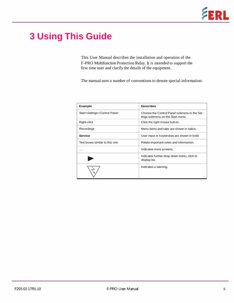
Pickup THD-V: (V,C,S) Pickup Delay: (V,C,S) VTS Blocking: (V,C,S) Trip Circuit Supervision (V,C,S) Fn. 74TCS_1 (V,C,S)
Function: (V,C,S) Name:: (V,C,S)
10. Using the IED
10-15 F-PRO User Manual F295-02-17R1.00
Drop-off Delay: (V,C,S) Fn. 74TCS_2 (V,C,S)
Function: (V,C,S) Name:: (V,C,S) Drop-off Delay: (V,C,S)
Count Alarm (V,C,S)
Fn. U/V Alarm (V,C,S)
Function: (V,C,S)
Pickup V: (V,C,S)
U/V count: (V,C,S)
Cnt Accum. Per: (V,C,S)
Fn. O/V Alarm (V,C,S)
Function: (V,C,S)
Pickup V: (V,C,S)
O/V count: (V,C,S)
Cnt Accum. Per: (V,C,S)
Fn. U/F Alarm (V,C,S)
Function: (V,C,S)
Pickup F: (V,C,S)
U/F count: (V,C,S)
Cnt Accum. Per: (V,C,S)
Fn. O/F Alarm (V,C,S)
Function: (V,C,S)
Pickup F: (V,C,S)
O/F count: (V,C,S)
Cnt Accum. Per: (V,C,S) Reset TR: (V,C,S)
Constant A: (V,C,S)
Constant B: (V,C,S) Constant P: (V,C,S) Current Compen: (V,C,S) Fn. S/I Alarm (V,C,S)
Function: (V,C,S)
Count Input: (V,C,S)

10. Using the IED
F295-03-17R1.10 F-PRO User Manual 10-16
Pickup Delay: (V,C,S) S/I count: (V,C,S) Cnt Accum. Per: (V,C,S)
Disturbance Record Settings (V,C,S)
Record Length: (V,C,S)
Pre-Trigger: (V,C,S)
Meters (V,C,S) Meter Display Option (V,C,S) Analog (V,C,S) VaMag: (V,C,S)
VaAng: (V,C,S)
VbMag: (V,C,S)
VbAng: (V,C,S)
VcMag: (V,C,S)
VcAng: (V,C,S)
VabMag: (V,C,S)
VabAng: (V,C,S)
VbcMag: (V,C,S)
VbcAng: (V,C,S)
VcaMag: (V,C,S)
VcaAng: (V,C,S)
VnMag: (V,C,S)
VnAng: (V,C,S)
VgMag: (V,C,S)
VgAng: (V,C,S)
VSyncM: (V,C,S)
VSyncA: (V,C,S)
ISefMa: (V,C,S)
ISefAn: (V,C,S)
V1Mag: (V,C,S)
V2Mag: (V,C,S)
V0Mag: (V,C,S)
%VF: (V,C,S)
%THD Voltage: (V,C,S)

10-17 F-PRO User Manual F295-03-17R1.10
10. Using the IED
Bus Voltage: (V,C,S)
Line Voltage: (V,C,S)
Bus Ph Angle: (V,C,S)
Line Ph Angle: (V,C,S)
Bus Frequency: (V,C,S)
Line Frequency: (V,C,S)
Digital (V,C,S)
DI (V,C,S)
EI1 (V,C,S)
EI2 (V,C,S)
EI3 (V,C,S)
EI4 (V,C,S)
DO (V,C,S)
RL1 (V,C,S)
RL2 (V,C,S)
RL3 (V,C,S)
RL4 (V,C,S)
RL5 (V,C,S)
RL6 (V,C,S)
RL7 (V,C,S)
RL8 (V,C,S)
Records (V,C,S)
View Events: (V,C,S)
View Faults: (V,C,S)
Utility (V,C,S)
Date and Time (V,C,S)
Date (V,C,S)
Time (V,C,S)
Display Time As (V,C,S)
UTC Offset (V,C,S)
Communication (V,C,S)
Com1-USB(Serial) (V,C,S)
Host: Serial Gadget (V,C,S)
COM2-RS485 (V,C,S)

10. Using the IED
F295-03-17R1.10 F-PRO User Manual 10-18
Protocol: (V,C,S)
Baud Rate: (V,C,S)
Parity: (V,C,S)
Relay Address: (V,C,S)
Com3-Ethernet (V,C,S)
IP Address: (V,C,S)
Port: (V,C,S)
Subnet Mask: (V,C,S)
Default Gateway: (V,C,S)
Mac Address: (V,C,S)
Erase Event Rec (C,S)
Erase Event Rec: (C,S)
Erase Fault Rec: (C,S)
Erase DR: (C,S)
Calibration (S)
Voltage & Current (S)
Calibrate VA (S)
Calibrate VB (S)
Calibrate VC (S)
Calibrate VG (S)
Calibrate VSync (S)
Calibrate Isef (S)
Password Settings (S)
Change PW (S)
New Change PW (S)
New Service PW (S)
PW Access Timer (V,S)
PW Access Timer (V,S)
PW Enable/Disable (S)
PW Enable: (S)
Firmware Update (S)
Confirm Update (S)
Test Mode (S)
Test Mode Selection (S)
10. Using the IED
10-19 F-PRO User Manual F295-03-17R1.10
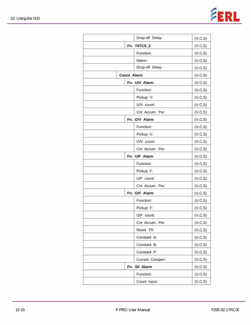
Unit Identifications (V,C,S)
Product Version: (V,C,S)
Serial Number: (V,C,S)
Unit ID: (V,C,S)
Firmware Ver: (V,C,S)
Settings Date: (V,C,S)
Settings Ver: (V,C,S)
RCP Ver: (V,C,S)
Comments: (V,C,S)
Station Name: (V,C,S)
Location: (V,C,S)
Bay Name: (V,C,S)
Load Date: (V,C,S)

F295-03-17R1.10 F-PRO User Manual 10-20
10. Using the IED
Where the access levels required to access each are indicated
V: view
C: change S: service
To login into the LCD menu structure, follow these steps:
2013Feb24 12:17
O-10122 Figure 10.2: Main Screen
In the Main Screen, Press Enter Key.
Figure 10.3: View / Change / Service: Choice Menu
In the View / Change / Service: Choose Menu screen, choose desired access level, and Press Enter key.
Figure 10.4: Enter Password
In the Enter PW screen, enter appropriate six digit password and Press Enter key on the return character (right bottom one)
Figure 10.5: Main Menu The Main Menu screen should appear. Note: The default passwords are below :(remove quotation marks)
1) View Access – no password for View access in LCD 2) Change Access “0”
3) Service Access “z”
F-PRO
Bay Name
View
Change
Enter PW
-------------
Configuration
Meters

10-21 F-PRO User Manual F295-03-17R1.10
10. Using the IED
10.4 Relay Control Panel
RCP is used for all user interface. A short description of the RCP configuration to connect to a relay is given here. Please refer to the Relay Control Panel User Manual for details.
Follow this sequence to configure RCP for USB link to the relay.
1. Execute Relay Control Panel.exe 2. Execute F-PRO Offliner.exe 3. Install Null Modem Driver. Please refer to the Relay Control Panel User Manual for details. 4. Run Relay Control Panel. Go to: Start > All Programs > ERLPhase > Relay Control Panel > Relay Control Panel First time RCP is run. Hit Add New.
“Add New Relay” Choose Communication > Direct Serial Link. Hit Get Information From Relay. Then RCP will communicate with the FPRO-216 and retrieve information to fill required fields. When this is done, hit Save Relay. If the window “Relay already exists...” pops up, you may need to re- name the relay changing the “Relay Name” in the “Relay Definition” category, before saving. After first time, in “Select Relay”, choose relay and hit Connect. In “Relay Password Prompt” Choose desired access level, enter appropriate password Note: Default passwords are listed below (remove the quotation marks)
View Access “v” Change Access “0” Service Access “z”
The basic structure of the Relay Control Panel information, including basic actions available, is given below:

F295-03-17R1.10 F-PRO User Manual 10-22
10. Using the IED
Notice that some options are not available (N/A) depending on the access level
Table 10.5: Relay Control Panel Structure
View Change Service
Relay Control Panel
Records Trigger Fault Trigger Fault
Trigger Event Trigger Event
Faults Erase Erase
Events Erase Erase
Metering
Analog Input View View View
I^2t View View View
Status (DI) View View View
Protection status View View View
Outputs (Status DO) View View View
ProLogic
Virtual
Utilities
Unit Identification View View View
Settings Group N/A Save Save
Time N/A Save Save
Analog Input Calibration N/A N/A Save
Virtual Inputs N/A Latch/Pulse Latch/Pulse
Toggle Outputs N/A N/A Close/Open
Set/Reset I^2t N/A Save Save
Password N/A N/A Save
Configuration
Present Settings (Get From
Relay) (Get From Relay)
(Get From Relay)
Saved Settings View
(Load to Relay)
(Load to Relay)

11-1 F-PRO User Manual F295-03-17R1.10
11 Protection Functions,Applications and Specifications
11.1 Protection and Recording Functions Introduction This section describes the equations and algorithms that define the F-PRO Protection
functions. The functions are 27/59DT-1to 6, 27/59IT-1 to 2, 24DT-1 to 2, 24IT, 47DT-1 to 2, 47IT, 59NDT-1 to 2, 59NIT, 59GDT-1 to 2, 59GIT, 81U/O-1 to 8, 81R-1 to 4, 25/27/59, 64/50SEF-1 to 2, 64/51SEF-1 to 2, 60VTS, 74TCS-1 to 2, THD-1 to 2,Counter alarm and Prologic have user-settable intentional pickup and drop off delay. The functions have alarm output when their pick up levels are exceeded. When the alarm occurs, the front alarm LED turns on and an output contact closes, if this option is selected in the output matrix settings. The alarm indication resets when the function reverts to reset state, if reset type is selected has Self Reset. A complete list of the settings and their range values can be found in ‘IED settings and Ranges’ in Appendix B.
27/59DT Phase (Definite Time Under /Over Voltage) The Phase Definite time (instantaneous) Under/Over voltage function has 6 stages.
Each individual stage consists of both time delayed and instantaneous protection.
This relay provides protection against under or over voltage from bus/line PT’s.
OPERATION:
Under Voltage DT – Whenever the injected (rms/fundamental) value reaches the same or below the precise pick up value, this function gets operated. The drop out value of this function mainly depends on the % hysteresis.
Over Voltage DT – Whenever the injected (RMS/FUNDAMENTAL) value reaches the same or above the precise pick up value, this function gets operated. The drop out value of this function mainly depends on the % hysteresis.
Note: Both this function should mainly satisfy the logic gates i.e. OR, AND.60VTS function has been clearly explained in that respective protection function.

F295-03-17R1.10 F-PRO User Manual 11-2
11. Protection Function, Application and Specification
Fig: 27/59DT Under voltage / Overvoltage Logic Diagram
Table 11.1: 27/59DT - Phase Definite Time Under/Over Voltage Settings (No. of Stages – 6)
Setting Description Range Function Activation Enable/Disable Function Selection UV / OV
Measurement Input Fundamental / RMS
Input Type Ph-N / Ph-Ph
Output Gate AND / OR
Pickup V 3.0 to 250.0V
Hysteresis 1% to 80%
Pickup DTL Delay 0.00 to 999.99 Seconds
Reset DTL Delay 0.00 to 999.99 Seconds
VTS Blocking Enable/Disable

11. Protection Function, Application and Specification
11-3 F-PRO User Manual F295-02-17R1.00
27/59IT Phase (Inverse Time Under / Over Voltage) The Phase inverse time Under/Over voltage function has 2 stages. Each individual
stage consists of both time delayed and instantaneous protection. This relay provides protection against under or over voltage from bus/line PT’s. It comprises of DTL,IEC standard, extreme, long time inverse curve and user defined curve.
OPERATION:
Under Voltage IT – Whenever the injected (RMS/FUNDAMENTAL) value reaches the same or below the precise pick up value, this function gets operated based on curve settings. The drop out value of this function mainly depends on the % hysteresis.
Over Voltage IT – Whenever the injected (RMS/FUNDAMENTAL) value reaches the same or above the precise pick up value, this function gets operated based on curve settings. The drop out value of this function mainly depends on the % hysteresis.
Note: Both this function should mainly satisfy the logic gates i.e. OR, AND.60VTS function has been clearly explained in that respective protection function.
Fig:27/59 IT Under voltage / Overvoltage Logic Diagram
* Operate & Reset time of the inverse characteristics can be calculated using the respective formulas presented above:

11. Protection Function, Application and Specification
F295-03-17R1.10 F-PRO User Manual 11-4
Table 11.2: IEC Curves
Sl.No. Characteristic A B p
1
Definite Time Lag
1.0
1.0
1.0
2
IEC Standard Inverse
1.0
0.0
1.0
3
IEC Extreme Inverse
40.0
1.0
2.0
4
IEC Long Time Inverse
5.0
2.0
2.0
5
User-defined
0.10 to 50.0
0.0 to 10.0
0.1 to 10.0
Table 11.3: 27/59IT Phase Inverse Time Under / Over Voltage Settings (No. of Stages – 2)
Setting Description Range Function Activation Enable / Disable Function Selection UV / OV
Measurement Input Fundamental / True RMS
Input Type Ph-N / Ph-Ph
Output Gate AND / OR
Pickup V 3.0 to 250.0 V
Hysteresis 1% to 80%
Curve Type For details see Table 11.2 “IEC Curves” on page 11-4
TMS 0.01 to 10.00
Pickup DTL Delay 0.00 to 999.99 seconds
Reset DTL Delay 0.0 to 999.99 seconds if chosen for user defined characteristics
A 0.1 to 50.0 settable if chosen for user defined characteristics
B 0.0 to 10.0 settable if chosen for user defined characteristics
P 0.1 to 10.0 settable if chosen for user defined characteristics VTS Blocking Enable/disable

11. Protection Function, Application and Specification
11-5 F-PRO User Manual F295-03-17R1.10
24DT (DEFINITE TIME OVERFLUX)
The over flux protection is used to detect the impermissible over flux condition in electrical equipment, which can endanger eg: transformers, generators. These are caused due to the increase in voltage and decrease in frequency.
The magnetic flux is directly proportional to voltage and inversely to its frequency. This is of the form,
Φ = V/F
OPERATION:
Whenever the injected (RMS/FUNDAMENTAL) value reaches the same or above the precise pick up (v/f) value, this function gets operated. The drop out value of this function varies with the % hysteresis.
Note: Both this function should mainly satisfy the logic gates i.e. OR, AND.60VTS function has been clearly explained in that respective protection function.
Fig: 24 DT over flux Logic Diagram
Table 11.4. 24DT Definite Time Over flux Settings (No. of Stages – 2)
Setting Description Range
Function Activation Enable/disable
Measurement Input Fundamental / RMS
Input Type Ph-N / Ph-Ph
Output Gate AND / OR
Pickup 1.00 to 3.00 per unit. Hysteresis 1 to 80% Pickup DTL Delay 0.00 to 999.99 seconds Reset DTL Delay 0.00 to 999.99 seconds
VTS Blocking Enable/disable

11. Protection Function, Application and Specification
F295-03-17R1.10 F-PRO User Manual 11-7
24IT INVERSE TIME OVER FLUX The over flux protection is used to detect the impermissible over flux condition in
electrical equipment, which can endanger eg: transformers, generators. These are caused due to the increase in voltage and decrease in frequency.
The magnetic flux is directly proportional to voltage and inversely to its frequency. This is of the form,
Φ = V/F
OPERATION: Whenever the injected (RMS/FUNDAMENTAL) value reaches the same or above the precise pick up (v/f) value, this function gets operated. The drop out value of this function varies with the % hysteresis.
Note: Both this function should mainly satisfy the logic gates i.e. OR, AND.60VTS function has been clearly explained in that respective protection function.
Fig: 24 IT Inverse Time over flux Logic Diagram
For IEC 1: = ( )
For ANSI 1,2,3: = ( ∗ )/
For Inverse Curve: =
= + ( ∗ ) − .

11. Protection Function, Application and Specification
F295-03-17R1.10 F-PRO User Manual 11-7
=
Table 11.5. 24IT Inverse Time Over flux Settings (No. of Stages – 1) Setting Description Range Function Activation Enable / Disable Measurement Input Fundamental / RMS
Input Type Ph-N / Ph-Ph
Output Gate AND / OR
Pickup V/F 1.00 to 1.50/2.00/3.00 per unit. Hysteresis 1 to 80%
Curve type For details see Table 11.2 “IEC Curves” on TMS 0.01 to 10.00 seconds Pickup DTL Delay 0.00 to 999.99 seconds Reset Delay DTL / ANSI Decay Reset DTL Delay 0.0 to 99.99 seconds Constant A Constant Value based on Curve Type Constant B 0.01 to 10.00 Constant C Constant Value based on Curve Type Constant K Constant Value based on Curve Type Inverse K 0.01 to 99.90 (For Inverse Curve only) User define set points X1 to X7 1.00 to 3.00 Per Unit User define set points Y1 to Y7 0.05 to 9999.99 seconds
VTS Blocking Enable / Disable
11. Protection Function, Application and Specification
11-8 F-PRO User Manual F295-02-17R1.00
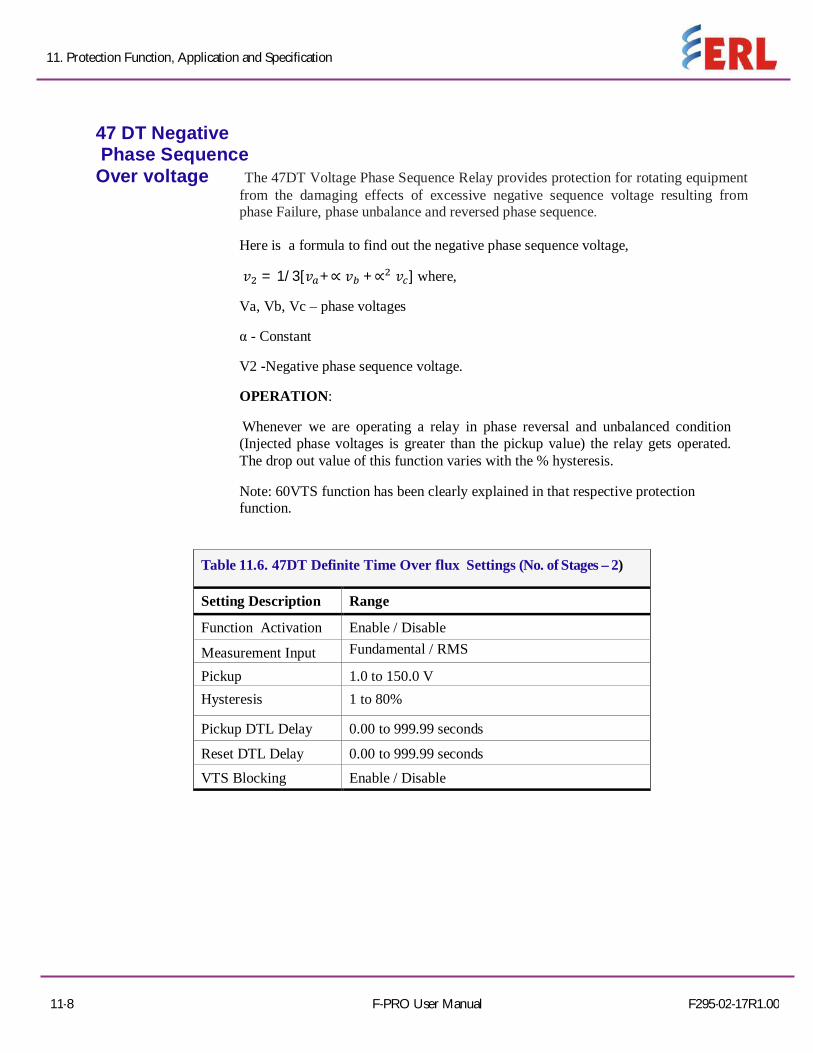
47 DT Negative Phase Sequence Over voltage The 47DT Voltage Phase Sequence Relay provides protection for rotating equipment
from the damaging effects of excessive negative sequence voltage resulting from phase Failure, phase unbalance and reversed phase sequence.
Here is a formula to find out the negative phase sequence voltage,
= 1/3[ +∝ +∝ ] where,
Va, Vb, Vc – phase voltages
α - Constant
V2 -Negative phase sequence voltage.
OPERATION:
Whenever we are operating a relay in phase reversal and unbalanced condition (Injected phase voltages is greater than the pickup value) the relay gets operated. The drop out value of this function varies with the % hysteresis.
Note: 60VTS function has been clearly explained in that respective protection function.
Table 11.6. 47DT Definite Time Over flux Settings (No. of Stages – 2)
Setting Description Range
Function Activation Enable / Disable
Measurement Input Fundamental / RMS
Pickup 1.0 to 150.0 V Hysteresis 1 to 80%
Pickup DTL Delay 0.00 to 999.99 seconds
Reset DTL Delay 0.00 to 999.99 seconds
VTS Blocking Enable / Disable

11. Protection Function, Application and Specification
F295-03-17R1.10 F-PRO User Manual 11-9
47 IT (Inverse Negative Over voltage) The 47IT Voltage Phase Sequence Relay provides protection for rotating equipment
from the damaging effects of excessive negative sequence voltage resulting from phase Failure, phase unbalance and reversed phase sequence.
Here is a formula to find out the negative phase sequence voltage,
= 1/3[ +∝ +∝ ] where,
Va, Vb, Vc – phase voltages
α - Constant
V2 -Negative phase sequence voltage.
OPERATION:
Whenever we are operating a relay in phase reversal and unbalanced condition (Injected phase voltages is greater than the pickup value) the relay gets operated based on curve settings. The drop out value of this function varies with the % hysteresis. It consists of DTL, IEC standard inverse curve, User defined curves.
( 2) = +
Note: 60VTS function has been clearly explained in that respective protection function.
Table 11.7. 47IT Inverse Time Over flux Settings (No. of Stages – 2)
Setting Description Range
Function Activation Enable / Disable
Measurement Input Fundamental / RMS
Pickup V2 1.0 to 150.0 V Hysteresis 1 to 80% Curve type For details see Table 11.2 “IEC Curves” on
page 11-4
TMS 0.01 to 10.00
Pickup DTL Delay 0.00 to 999.99 seconds
Reset DTL Delay 0.00 to 999.99 seconds A 0.1 to 50.0 settable if chosen for
user defined characteristics B 0.0 to 10.0 settable if chosen for user
defined characteristics P 0.1 to 10.0 settable if chosen for user defined characteristics VTS Blocking Enable / Disable

11. Protection Function, Application and Specification
F295-03-17R1.10 F-PRO User Manual 11-11
59NDT Derived Residual Definite Time Overvoltage This function provides protection against ground faults irrespective of the system
grounding connection used.
Depending on the VT configuration, the protection will operate from an internally calculated value from the 3 phase to neutral voltage measurements or a directly measured value of residual voltage from a broken delta VT or from the secondary winding of a distribution transformer ground at the generator neutral.
OPERATION:
This protection function works based on the injected voltage (unbalanced), this unbalanced voltage flows through the ground via neutral.
Whenever the neutral voltage (Vn) reaches the same or above the pickup value then the relay gets operated.
The dropout voltage mainly depends on the % hysteresis.
Note: 60VTS function has been clearly explained in that respective protection function.
Table 11.8. 59NDT Derived Residual DT Settings (No. of Stages – 2)
Setting Description Range
Function Activation Enable / Disable
Measurement Input Fundamental / RMS
Pickup 1.0 to 250.0 V Hysteresis 1 to 80%
Pickup DTL Delay 0.00 to 999.99 seconds
Reset DTL Delay 0.00 to 999.99 seconds VTS Blocking Enable / Disable

11. Protection Function, Application and Specification
F295-03-17R1.10 F-PRO User Manual 11-11
59NIT Derived Residual Inverse Time Overvoltage This function provides protection against ground faults irrespective of the system
grounding connection used.
Depending on the VT configuration, the protection will operate from an internally calculated value from the 3 phase to neutral voltage measurements or a directly measured value of residual voltage from a broken delta VT or from the secondary winding of a distribution transformer ground at the generator neutral.
OPERATION:
This protection function works based on the injected voltage (unbalanced), this unbalanced voltage flows through the ground via neutral.
Whenever the neutral voltage (Vn) reaches the same or above the pickup value based on the selected curve, the relay gets operated.
( ) = +
The dropout voltage mainly depends on the % hysteresis.
Note: 60VTS function has been clearly explained in that respective protection function.
Table 11.9. 59NIT Derived Residual IT Overvoltage Settings
Setting Description Range
Function Activation Enable / Disable
Measurement Input Fundamental / RMS
Pickup 1.0 to 250.0 V
Hysteresis 1 to 80%
Curve type For details see Table 11.2 “IEC Curves” on page11-4
TMS 0.01-10
Pickup DTL Delay 0.00 to 999.99 seconds Reset DTL Delay 0.00 to 999.99 seconds
A 0.1 to 50.0 settable if chosen for user defined characteristics
B 0.0 to 10.0 settable if chosen for user defined characteristics
P 0.1 to 10.0 settable if chosen for user defined characteristics
VTS Blocking Enable / Disable

11. Protection Function, Application and Specification
11-12 F-PRO User Manual F295-03-17R1.10
59GDT Measured Residual Definite Time Overvoltage This function provides protection against ground faults irrespective of the system
grounding connection used.
Depending on the VT configuration, the protection will operate from an internally calculated value from the 3 phase to neutral voltage measurements or a directly measured value of residual voltage from a broken delta VT or from the secondary winding of a distribution transformer ground at the generator neutral.
OPERATION:
o This protection function works based on the injected voltage (unbalanced), this unbalanced voltage flows through the ground via neutral.
o Whenever the ground voltage (Vg) reaches the same or above the pickup value then the relay gets operated.
o The Ground voltage can be obtained from the connection diagram of the relay especially in the Vg.
o The dropout voltage mainly depends on the % hysteresis.
Note: 60VTS function has been clearly explained in that respective protection function.
Table 11.10. 59GDT Measured Residual DT Settings (No. of Stages – 2)
Setting Description Range
Function Activation Enable / Disable
Measurement Input Fundamental / RMS
Voltage compensation 0.0 to 15.0V Pickup(Vg) 1.0 to 250.0 V
Hysteresis 1 to 80%
Pickup DTL Delay 0.00 to 999.99 seconds
Reset DTL Delay 0.00 to 999.99 seconds

11. Protection Function, Application and Specification
F295-03-17R1.10 F-PRO User Manual 11-13
59GIT Measured Residual Inverse Time Overvoltage This function provides protection against ground faults irrespective of the system
grounding connection used.
Depending on the VT configuration, the protection will operate from an internally calculated value from the 3 phase to neutral voltage measurements or a directly measured value of residual voltage from a broken delta VT or from the secondary winding of a distribution transformer ground at the generator neutral.
OPERATION: This protection function works based on the injected voltage (unbalanced), this
unbalanced voltage flows through the ground via neutral. Whenever the ground voltage (Vg) reaches the same or above the pickup value based
on the type of curve, the relay gets operated. The Ground voltage can be obtained from the connection diagram of the relay
especially in the Vg.
( ) = +
− 1
The dropout voltage mainly depends on the % hysteresis. Note: 60VTS function has been clearly explained in that respective protection function.
Table 11.11. 59GIT Measured Residual IT Overvoltage Settings
Setting Description Range
Function Activation Enable / Disable Measurement Input Fundamental / RMS
Voltage compensation 0.0 to 15.0 V
Pickup 1.0 to 250.0 V Hysteresis 1 to 80% Curve type For details see Table 11.2 “IEC Curves” on page 11-4
TMS 0.01-10.00
Pickup DTL Delay 0.00 to 999.99 seconds Reset DTL Delay 0.00 to 999.99 seconds
A 0.1 to 50.0 settable if chosen for user defined characteristics
B 0.0 to 10.0 settable if chosen for user defined characteristics
P 0.1 to 10.0 settable if chosen for user defined characteristics

11. Protection Function, Application and Specification
11-14 F-PRO User Manual F295-03-17R1.10
81 U/O Under/ Over frequency Over frequency: Over frequency arise due to excess of power generation and it can
easily be corrected by reduction in the power Outputs with the help of the governor or manual control.
Under frequency: Under frequency occurs due to the excess of load. During an overload, generation capability of the generator increases and reduction in frequency occurs. The power system survives only if we drop the load so that the generator output becomes equal or greater than the connected load. If the load increases the generation, then frequency will drop and load need to shed down to create the balance between the generator and the connected load. The rate at which frequency drops depend on the time, amount of overload and also on the load and generate or variations as the frequency changes. Frequency decay occurs within the seconds so we cannot correct it manually. Therefore automatic load shedding facility needs to be applied.
OPERATION:
The over frequency protection function operates, when the injected value Of frequency is same or greater than the pickup value.
The under frequency function operates, when the injected value of frequency is equal
or lesser than the pickup value.
The dropout voltage mainly depends on the % hysteresis.
Note: 60VTS function has been clearly explained in that respective protection function.
Table 11.12. 81U/O frequency Settings (No. of Stages – 8)
Setting Description Range
Function Activation Enable / Disable
Functional selection UF / OF
Pickup (F) 40.00 to 60.00 Hz Hysteresis 1 to 80%
Pickup Delay 0.00 to 999.99 seconds
VTS Blocking Enable / Disable

11. Protection Function, Application and Specification
F295-03-17R1.10 F-PRO User Manual 11-15
81 R Rate of change of frequency Rate of change of frequency (ROCOF or df/dt):- It is used for fast load shedding, to
speed up operation time in over- and under-frequency situations and to detect loss of grid. For example a centralized dedicated load shedding relay can be omitted and replaced with distributed load shedding, if all outgoing feeders are equipped with protection devices. A special application for ROCOF is to detect loss of grid (loss of mains, islanding). The more the remaining load differs from the load before the loss of grid, the better the ROCOF function detects the situation.
Over frequency: Over frequency arise due to excess of power generation and it can easily be corrected by reduction in the power Outputs with the help of the governor or manual control.
Under frequency: Under frequency occurs due to the excess of load. During an overload, generation capability of the generator increases and reduction in frequency occurs. The power system survives only if we drop the load so that the generator output becomes equal or greater than the connected load. If the load increases the generation, then frequency will drop and load need to shed down to create the balance between the generator and the connected load. The rate at which frequency drops depend on the time, amount of overload and also on the load and generate or variations as the frequency changes. Frequency decay occurs within the seconds so we cannot correct it manually. Therefore automatic load shedding facility needs to be applied.
OPERATION:
Whenever the rate of change of frequency reaches same or above (If set Pickup is Positive values) the pickup value, then this function gets operated.
Whenever the rate of change of frequency reaches same or below (If set Pickup is Negative values) the pickup value, then this function gets operated.
The dropout voltage mainly depends on the % hysteresis.
Note: 60VTS function has been clearly explained in that respective protection function.
Table 11.13. 81R ROCOF Settings (No. of Stages – 4)
Setting Description Range
Function Activation Enable / Disable
Pickup (df/dt) -10 to 10 Hz Hysteresis 1 to 80%
Pickup Delay 0.00 to 999.99 seconds
VTS Blocking Enable / Disable

11. Protection Function, Application and Specification
11-16 F-PRO User Manual F295-03-17R1.10
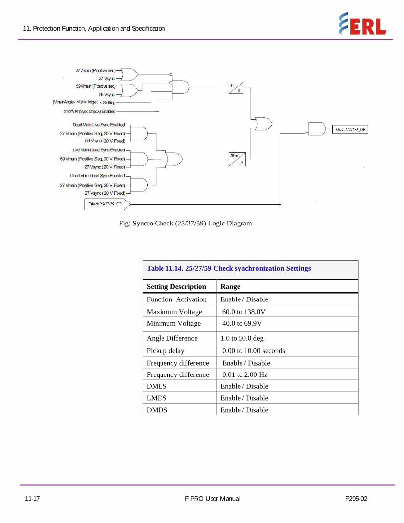
25/27/59 Check Synchronization The relay can bring in voltages from both line and bus PTs. The Line Sync
Check function, if enabled, looks at the voltage steady state angle between the line and bus PT voltage. If this angle is within a plus/minus specified value, (+/ - 1 to 50 degree magnitude range of setting available), the function enables a definite time delay pickup (user-selectable 0 to 10 seconds) after which time and output is produced.
The line sync reference voltage is taken from a bus source. The relay can bring one single phase-to-neutral voltage. Logic within the relay allows the single phase quantity to be either A, B or C phase. All unused single-phase inputs must be grounded for proper operation. The Dead Main Live Auxiliary (DMLA), Live Main Dead Auxiliary (LMDA) and Dead Main Dead Auxiliary (DMDA) logic functions use fixed values of main and auxiliary positive sequence secondary voltages to determine the Sync Check condition. The voltage is fixed at 20 V secondary, voltages below 20 V are declared a dead state and voltages above 20 V are declared a live state. When enabled, this function checks that the voltage angle between the line PT and bus PT are within a specified value. Use this function to ensure that closing a line to a system will result in acceptable power flow. The function uses positive sequence voltage, and therefore, can accommodate single-phase sources as well as 3-phase sources. If a single-phase source is used, it must be connected to the corresponding phase designation on the relay input. For example: If only a B-phase bus PT is available, it should be connected to the relay input B phase terminals. In this example, the voltage and angle limit is 20 degrees with no pickup or drop out delay. The Dead Main Live Auxiliary, Live Main Dead Auxiliary and Dead Main Dead Auxiliary logic functions use fixed values of main and auxiliary positive sequence secondary voltages to determine the sync check condition. The voltage is fixed at 20 V secondary. Voltages below 20 V are declared a dead state and voltages above 20 V are declared a live state.
Note: 60VTS function has been clearly explained in that respective protection function.
11. Protection Function, Application and Specification
11-17 F-PRO User Manual F295-02-
Fig: Syncro Check (25/27/59) Logic Diagram
Table 11.14. 25/27/59 Check synchronization Settings
Setting Description Range
Function Activation Enable / Disable
Maximum Voltage 60.0 to 138.0V Minimum Voltage 40.0 to 69.9V
Angle Difference 1.0 to 50.0 deg
Pickup delay 0.00 to 10.00 seconds
Frequency difference Enable / Disable Frequency difference 0.01 to 2.00 Hz DMLS Enable / Disable LMDS Enable / Disable DMDS Enable / Disable

11. Protection Function, Application and Specification
F295-03-17R1.10 F-PRO User Manual 11-18
67/64/50 Instantaneous Sensitive Earth Fault
The sensitive earth fault protection works by measuring the residual current across the three phases in a system. This is done using a Core balanced current transformer (CBCT). In the event of a fault, the residual current over the three phases will not be equal to zero as the current from the faulted phase flows through the earth. The sensitive earth fault protection is usually used in alternators and transformers with high resistance grounding. High resistance grounding restricts the earth fault current to less than 10A. High resistance grounding enables electrical systems to continue running when one of the phases is faulted. This prevents interruptions to the power supply. This kind of earthing system provides time to identify and isolate the fault.
Once an earth fault occurs in the high resistance grounding system, an alarm needs to be generated and the fault needs to be traced. For this a reliable protection which detects earth faults even when the fault current is very low is necessary. Undetected earth faults in this system are dangerous as a second earth fault in another phase may result in a short- circuit. Conventional earth fault relays may not be accurate in detecting an earth fault at such low current values.
The sensitive earth fault protection, as the name suggests, is a highly sensitive relay. It can sense currents as low as 0.2% of the CT secondary current.
The sensitive earth fault relay may be configured to either generate an alarm or a trip signal.
OPERATION: Non directional - For this function the relay will operates irrespective of the angle as the name suggests when the injected voltage and current is same or above the pickup value. In this function, pickup voltage value will not take in to account. Directional(FWD & REV) – For this function the relay gets operated by considering the polarization characteristics angle(whether fwd or rev direction) and the injected voltage and current is same or above the pickup value

11. Protection Function, Application and Specification
11-19 F-PRO User Manual F295-03-17R1.10
Table 11.15. 67 SEF Settings
Setting Description Range
Characterizing angle -95 to + 95 degrees
Minimum voltage 0.3 to 40.0 V Measurement I/P VN / V2
VTS Blocking Enable / Disable
Table 11.16. 64/50 SEF Settings
Setting Description Range
Function Activation Enable / Disable
Direction selection Non Dir / FWD / REV Measurement I/P Fundamental / RMS
Pickup Isef >> 0.005 to 3.000 A
Pickup Delay 0.00 to 999.99 seconds
Current compensation 0.000 to 0.500 A

11. Protection Function, Application and Specification
11-20 F-PRO User Manual F295-03-17R1.10
60 VTS Voltage Supervision function is to detect loss of single, two or even all there phases
voltage inputs to relay. The voltage fail may happen due to internal faults in voltage transformer or due to human errors such as faults in terminal wirings to relay. This causes mal-operation of directional elements and the consequence is instability of power system. Thus VT Supervision function is incorporated in the directional relay. This function on detection of VT fail, blocks the protection functions. The function detects VT fail on the basis that during single or two phase VT fail, there will be presence of negative sequence voltage but the negative sequence current which usually accompanies it during normal unbalance will not be present. But, during three phases VT fails, there will not be even negative sequence voltage. At that time, it works as per the logic settings that have been loaded. If the negative and positive sequence voltage exceeds the set value, the function is blocked as it will increase on a fault only. OPERATION: Condition 1: Whenever the Injected neutral voltage (Vn) is less than the Pickup value, the relay gets operated.
Condition 2: Whenever the Injected Phase - Phase voltage (V3ph) is more than the Pickup value, the relay gets operated.
Condition 3: Whenever there is no potential in any one of the phases, the relay gets operated.
Table 11.17. 60 VTS Settings
Setting Description Range
Function Activation Enable / Disable
Pickup Vn > 1.0 to 40.0 V
Pickup V3ph < 1.0 to 40.0 V Pickup delay 0.10 to 999.99 seconds
CB check status Enable / Disable

11. Protection Function, Application and Specification
11-21 F-PRO User Manual F295-03-17R1.10
THD Total harmonic
Distortion Total harmonic distortion, or THD, is the summation of all harmonic components of the voltage or current waveform compared against the fundamental component of the voltage or current wave.
% THD =⋯
V1 – Nominal voltage i.e voltage at normal condition say for eg, 63.5V. V2 - Harmonic voltage of 2nd order.
OPERATION: Whenever the injected harmonic voltage is same or above the %THD voltage, the relay gets operated.
Table 11.18. THD Settings
Setting Description Range Function Activation Enable / Disable Pickup THD-V 1 to 100% Pickup delay 0.00 to 999.99 seconds
VTS blocking Enable / Disable
74 Trip Circuit Supervision (TCS) Trip Circuit Supervision Relay is an electronic-circuit based relay which is used to
monitor and supervise the integrity of circuit breakers trip coil and other wiring circuits of low-voltage and medium-voltage network.
Trip Circuit Supervision Relay is connected with a circuit breaker to monitor the trip circuit positions (open or closed).
Trip Circuit Supervision Relay generates a trip circuit failure alarm, either if the trip circuit supply is disconnected or if the trip circuit connection is changed to an open circuit. OPERATION: This function needs an external input for triggering when the function is enabled. When this external input is triggered Table 11.19. 74 TCS Settings
Setting Description Range
Function Activation Enable / Disable
Name User Defined
Drop off delay 0.00 to 9.99 seconds

11. Protection Function, Application and Specification
F295-03-17R1.10 F-PRO User Manual 11-22
Counter Alarm UNDER VOLTAGE:
This function operates based on the pickup value, U/V count and number of days. Whenever the injected value is same or below the pickup value with the appropriate count and duration setting, the relay will get operated.
OVER VOLTAGE: This function operates based on the pickup value, O/V count and number of days. Whenever the injected value is same or above the pickup value with the appropriate count and duration setting, the relay will get operated.
UNDER FREQUENCY: This function operates based on the pickup value, U/F count and number of days. Whenever the injected value is same or below the pickup value with the appropriate count and duration setting, the relay will get operated.
OVER FREQUENCY: This function operates based on the pickup value, O/F count and number of days. Whenever the injected value is same or above the pickup value with the appropriate count and duration setting, the relay will get operated.
STATUS I/P: Whenever the external input increase beyond the count limit with the prompt duration setting, the relay gets operated.
Table 11.20. COUNTER ALARM- UV Settings
Setting Description Range
Function Activation Enable / Disable
Pickup value 1.0 to 220.0 V
U/V count 1 to 1000 Count Acc period 1 to 31 days
Table 11.21. COUNTER ALARM- OV Settings
Setting Description Range
Function Activation Enable / Disable
Pickup value 1.0 to 220.0 V
O/V count 1 to 1000 Count Acc period 1 to 31 days

11. Protection Function, Application and Specification
11-23 F-PRO User Manual F295-02-17R1.00
Table 11.22. COUNTER ALARM- UF Settings
Setting Description Range
Function Activation Enable / Disable
Pickup value 40.00 to 50.00 Hz
U/F count 1 to 1000 Count Acc period 1 to 31 days
Table 11.23. COUNTER ALARM- OF Settings
Setting Description Range
Function Activation Enable / Disable
Pickup value 40.00 to 50.00 Hz
O/F count 1 to 1000 Count Acc period 1 to 31 days
Table 11.24. COUNTER ALARM- SI Settings
Setting Description Range
Function Activation Enable / Disable
Count I/P SI1 / SI2 / SI3 / SI4
Pickup delay 0.00 to 99.99 seconds
S/I count 1 to 1000 Count Acc period 1 to 31 days

F295-03-17R1.10 F-PRO User Manual 11-24
11. Protection Function, Application and Specification
ProLogic ProLogic Control Statements Using ProLogic, F-PRO can pick-up any of the protection functions or external inputs and place them into Boolean-like statements. ProLogic handles up to five functions to generate one ProLogic statement and 20 statements are possible. The results from these statements are mapped to output contacts using the output matrix.
Special ProLogic inputs are:
• Virtual Inputs#1 as an input to ProLogic.
The ProLogic control statements are used to create Boolean-like logic. The F- PRO can use any of the protection functions or external inputs combined with logic gates to create a ProLogic control statement. The possible gates are AND, NAND, OR, NOR, XOR, NXOR, and LATCH. The control can be time delay pickup and or time delay dropout, and can drive the front panel target LED. 20 ProLogic control statement outputs are available and can be used in the output matrix to customize the relay to customer specific needs. Inputs to ProLogic are all the elements plus previous ProLogic statements for logic nesting usage.
Table 11.25: ProLogic Function settings
Setting Description Range
Function Activation Enable / Disable Name User define (Up to 12 Characters)
Pickup Delay - Tp 0.00 to 999.00 seconds
Dropout Delay - Td 0.00 to 999.00 seconds
Number of Inputs Up to 5 (Input A,B,C,D,E)
Operators Boolean-type logic gates
The example shows A to E inputs are status points of functions that are user-selectable. Each ProLogic output can be given a specific name, pickup and reset time delay.
Figure 11.1: ProLogic

11-25 F-PRO User Manual F295-03-17R1.10
11. Protection Function, Application and Specification
11.2 Recording Functions The F-PRO Relay provides numerous recording and logging functions, including a
fault recorder and an event log to analyze faults, to know the performance of the relay and to observe the status of the protection and to review the operation of the overall protection scheme.
Record Duration and Extension The length of each record is determined by the Record Length setting. Fault record
lengths can be set between 1 and 20 seconds. Pre-trigger times can be fixed from 0.1 to 0.5 seconds for fault records and are included as part of the normal record length.
F-PRO relay automatically extends a record as required to capture consecutive triggers that are close together. If a trigger occurs while a recording is in progress, the record is stretched to include the full post-trigger time of subsequent triggers, up to a maximum length — 20 seconds for fault records. If a trigger occurs before the end of a record caused by a previous trigger, but too late to allow sufficient post-trigger time in a maximum extended record, a new over- lapping record is created.
The normal record lengths settings are accessible in the Configuration >Disturbance record setting >Record Length option settings, and can be set from either the HMI or the Offliner Set-tings software.
Event Recording The event recording provides permanent storage of the event log. An event record can be created automatically or manually.
Recording can be initiated manually through Relay Control Panel. The command Trigger Event is available under the Records menu.
Record Storage The F-PRO compresses records on the fly, achieving a typical lossless compression rate of 4:1. As a result, the F-PRO can store up to 4000 seconds of fault recordings in non-volatile storage. If the storage is full, new records automatically overwrite the oldest, ensuring that the recording function is always available.
Retrieval and Analysis A list of stored records is available through the Relay Control Panel in the Records tab.
From Relay Control Panel you can retrieve the record and delete or leave on the relay, graph the record, export the record to COMTRADE. Records are named by combining the Unit ID setting with the date and time of the initiating record trigger.

11. Protection Function, Application and Specification
F295-03-17R1.10 F-PRO User Manual 11-26
To delete a record from storage, right-click on the record and select Delete, or alternatively, select the record and press the <Del> key. You can also do group deleting and group transferring.
To select multiple records 1. Select a record 2. Hold the <Shift> key. 3. Continue selecting records until all desired records are selected.
4. Press the <Del> key. A message asks “Are you sure you want to delete multiple records from the relay?” shown above. Select Delete and the
files are deleted. When a record is retrieved from the relay using Relay Control Panel program, it is automatically transferred to your PC as well. The record is placed in your Relay Control Panel program’s Recordings folder. The Relay Control Panel's default Recordings folder can be set when the relay is initially connected to the PC, as shown in the following image.
Figure 11.2: Recording Folder
When transferred to your computer, the record name remains unchanged and the file extension indicates the record type: .fpr for transient recording, and .fpe for an event recording.

11. Protection Function, Application and Specification
11-27 F-PRO User Manual F295-03-17R1.10
11.3 Logging Functions Event Log Logged events include trips, alarms, external input assertions plus internal events such
as setting changes. Fault information and classification information is included in event messages where appropriate. For example, the event log entry for a function trip might be:
2016 Oct 21, 15:34:19.832: 51-1 ABC Operated.
The event log can be viewed in three ways:
• Relay Front HMI
• Relay Control Panel interface is in the Events tab
• SCADA protocols included in the F-PRO allow the SCADA server/client access to Trip and Alarm event data.
Events that occur during a transient fault recording are also embedded in the transient record and can be viewed in Relay Control Panel, RecordBase View and RecordGraph. Although the event log is circular, you may ensure events are not lost by checking the manual trigger option on the records menu in Relay Control Panel. When this option is selected, as the event log is required by user, it will save the records to an event file .fpe. The event log will then be ready to capture up to 1000 new events.
This display is a snapshot of the event list which must be manually refreshed to display new events that occur while the display is up.
There is a list of the F-PRO event messages. For details see “Event Messages” in Appendix D
Fault Log The F-PRO stores a log of faults in a 20 entry circular log. Each entry contains the time
of the fault, fault type, faulted phase, fault quantities as per the below table. Fault log will be triggered only for trip condition and it won't log for an alarm condition.
Table 11.26: Fault Log
Fault Type Fault Quantities
27DT-1 Phase Indication VA/VB/VC/VN
27DT-2 Phase Indication VA/VB/VC/VN 27DT-3 Phase Indication VA/VB/VC/VN 27DT-4 Phase Indication VA/VB/VC/VN 27DT-5 Phase Indication VA/VB/VC/VN 27DT-6 Phase Indication VA/VB/VC/VN 27IT-1 Phase Indication VA/VB/VC/VN 27IT-2 Phase Indication VA/VB/VC/VN

11. Protection Function, Application and Specification
F295-03-17R1.10 F-PRO User Manual 11-28
Table 11.27: Fault Log
59DT-1 Phase Indication VA/VB/VC/VN
59DT-2 Phase Indication VA/VB/VC/VN
59DT-3 Phase Indication VA/VB/VC/VN
59DT-4 Phase Indication VA/VB/VC/VN
59DT-5 Phase Indication VA/VB/VC/VN
59DT-6 Phase Indication VA/VB/VC/VN
59IT-1 Phase Indication VA/VB/VC/VN
59IT-2 Phase Indication VA/VB/VC/VN
24DT-1 Phase Indication VA/VB/VC/%V/F
24DT-2 Phase Indication VA/VB/VC/%V/F
24IT Phase Indication VA/VB/VC/%V/F
47DT-1 VA/VB/VC/V2
47DT-2 VA/VB/VC/V2
47IT VA/VB/VC/V2
59NDT-1 VA/VB/VC/VN
59NDT-2 VA/VB/VC/VN
59NIT VA/VB/VC/VN
59GDT-1 VA/VB/VC/VG
59GDT-2 VA/VB/VC/VG
59GIT VA/VB/VC/VG
81U-1 VA/VB/VC/Freq
81U-2 VA/VB/VC/Freq
81U-3 VA/VB/VC/Freq
81U-4 VA/VB/VC/Freq

11. Protection Function, Application and Specification
11-29 F-PRO User Manual F295-03-17R1.10
Table 11.28: Fault Log
81U-5 VA/VB/VC/Freq
81U-6 VA/VB/VC/Freq
81U-7 VA/VB/VC/Freq
81U-8 VA/VB/VC/Freq
81O-1 VA/VB/VC/Freq
81O-2 VA/VB/VC/Freq
81O-3 VA/VB/VC/Freq
81O-4 VA/VB/VC/Freq
81O-5 VA/VB/VC/Freq
81O-6 VA/VB/VC/Freq
81O-7 VA/VB/VC/Freq
81O-8 VA/VB/VC/Freq
81R-1 VA/VB/VC/dF/dt
81R-2 VA/VB/VC/dF/dt
81R-3 VA/VB/VC/dF/dt
81R-4 VA/VB/VC/dF/dt
64/50SEF-1 VA/VB/VC/ISEF
64/50SEF-2 VA/VB/VC/ISEF
64/50SEF-3 VA/VB/VC/ISEF
64/50SEF-4 VA/VB/VC/ISEF
The fault log can be viewed in three ways:
• Relay Front HMI
• Relay Control Panel interface is in the Events tab
• SCADA protocol included in the F-PRO allows the SCADA Master / Client access to Trip event

F295-03-17R1.10 F-PRO User Manual 12-1
12 Data Communications 12.1 Introduction
This deals with data communications with the relay. First, the SCADA protocol is discussed, and it is then followed by the new IEC 61850 communication standard.
The SCADA protocol deals with the Modbus and IEC 60870-5-103 protocols. The SCADA configuration and its settings are described. The parameters for SCADA communications are defined using F-PRO Offliner software. Finally, details on how to monitor SCADA communications are given for maintenance and trouble shooting of the relay.
12.2 SCADA Protocol
Modbus Protocol
The relay supports either a Modbus RTU or Modbus ASCII SCADA connection. Modbus is available exclusively via a direct serial link. Serial Modbus communications can be utilized exclusively via serial com Port 2 (RS485 port), which is located on the rear of the relay. An external RS-232 to RS-485 converter is not required to connect the relay to an RS-485 network. For details on connecting to serial Port, see “Communication Port Details”
Complete details regarding the Modbus protocol emulation and data point lists can be found in “Modbus RTU Communication Protocol” in Appendix E’ on page Appendix E-1
IEC 103 Protocol The relay supports IEC 60870-5-103 SCADA connection. IEC 103 is available via a RS485 serial link.
Serial IEC 103 communications can be utilized exclusively via serial com Port 2. Port 2 (RS485 port) is located on the rear of the relay. An external RS-485 to RS-232 converter can be used to connect the relay to an RS- 232 network. For details on connecting to serial Port, see “Communicating with the Relay Intelligent Electronic Device (IED)” and “Communication Port Details”. Complete details regarding the IEC 103 protocol emulation and data point lists can be found in “Event Messages” in Appendix D.

12. Data Communications
12-2 F-PRO User Manual F295-03-17R1.10
Offliner SCADA Configuration
Details on using the Offliner software are available in “To Install Software on the Computer” on page -xiii. Details on downloading a completed settings file to the relay are available in “Sending a New Setting File to the Relay” on page 6-6.
Open the Offliner application according to the instructions found in the indicated section and highlight the SCADA Communication selection. The screen appears as follows.
Figure 12.1: SCADA Communications
The configuration of SCADA communication parameters via the Offliner application is very intuitive. Several settings options are progressively visible and available depending on other selections. As noted before, there is no field to configure the number of data and stop bits. These values are fixed as follows:
• Modbus Serial – 7 data bits, 1 stop bit
• IEC 60870-5-103 Serial – 8 data bits, 1 stop bit

12. Data Communications
F295-03-17R1.10 F-PRO User Manual 12-3
12.3 IEC 61850 Communication The IEC 61850 Standard
The Smart Grid is transforming the electrical power industry by using digital technology to deliver electricity in a more intelligent, efficient and controlled way. Embedded control and communication devices are central to this transformation by adding intelligent automation to electrical networks.
The IEC 61850 standard defines a new protocol that permits substation equipment to communicate with each other. Like many other well-known manufacturers, ERLPhase Power Technologies is dedicated for using IEC 61850-based devices that can be used as part of an open and versatile communications network for substation automation.
The IEC 61850 defines an Ethernet-based protocol used in substations for data communication. Substations implement a number of controllers for protection, measurement, detection, alarms, and monitoring. System implementation is often slowed down by the fact that the controllers produced by different manufacturers are incompatible, since they do not support the same communication protocols. The problems associated with this incompatibility are quite serious, and result in increased costs for protocol integration and system maintenance.
Implementation Details
The F-PRO conforms to IEC 61850-8-1, commonly referred to as Station Bus Protocol. Implementation includes the following documents “IEC 61850 Implementation” in Appendix L’ on page Appendix L-1:
• Protocol Implementation Conformance Statement
• Model Implementation Conformance Statement
• Tissues Conformance Statement Note that unit’s IP address can be used on the IEC61850 client side for unique unit identification instead of a physical device “PD Name”. The publisher configuration is fixed and defined in the ICD file and available for reading to any IEC61850 client. Subscriber functionality is also fixed and supported for the Virtual Inputs only.

13-1 F-PRO User Manual F295-03-17R1.10
13 Offliner Settings Software 13.1Introduction
This section deals with the Offliner Settings software. The Offliner settings software is used to create relay settings on a personal computer. Offliner provides an easy way to view and manipulate settings. Offliner supports all firmware versions and has the capability to convert older setting versions into newer ones.
In this section, first, the Offliner features are presented. The menu and tool bar are discussed and this is followed by a description of the Graphing and Protection functions.
Next, the Offliner feature, for handling backward compatibility with previous software versions is described. Also described are methods of converting a Settings File, sending a new Settings File to the relay and creating a Settings File from an older version of the software.
Next, the RecordBase View and RecordGraph to analyze the records from a relay are described.
This is followed by a lengthy description of the main branches from the Tree View. This section provides all information for Identification, System Parameters, SCADA Communication, IEC 103 Configuration, SCADA Settings summary, Record Length, Setting Groups, ProLogic, Breaker Logic, LED Matrix, Output Matrix, reset type for Led and output contact and Settings summary.
Finally, a description of how the settings on the relay can be viewed through the RecordBase View analysis software is provided.
Figure 13.1: Opening Screen
Setting Tree Setting area

13. Offliner Setting Software
F295-03-17R1.10 F-PRO User Manual 13-2
undo
13.2Offliner Features
The Offliner software includes the following menu and system tool bar.
Table 13.1: Windows Menu
Windows Menu Sub Menu Comment
Document Menu (Icon)
Restore Restores active window to previous size
Move Allows user to move active window
Size Allows user to resize active window
Minimize Makes the active window as small as possible
Maximize Makes the active window as large as possible
Close Closes the active Offliner setting document
Next Switches to the next open Offliner setting file, if more than setting file is being edited
new
open
save
cut
copy
paste
Help topics about F-PRO settings
Copy graph
Copy setting gropup
Show or hide Left Hand side tree
About

13. Offliner Setting Software
13-3 F-PRO User Manual F295-03-17R1.10
Table 13.1: Windows Menu
File New Opens up a default setting file of the most recent setting version
Open Open an existing setting file
Close Closes the active Offliner setting document
Save Saves the active setting file
Save As Saves the active setting file with a new name or to a new location
Print Prints graphs or setting summary depending on active screen
Print Preview Provides a print preview of the setting summary
Print Setup Changes printers or print options
1 – 8 The 8 most recently accessed setting files
Exit Quits the program and prompts to save the document if it is not saved
Edit Undo Undo last action
Cut Cut the selection and puts it on the clipboard
Copy Copy the selection and puts it on the clipboard
Paste Insert clipboard contents
Copy Graph Copy the graph for the active screen to the clipboard
Copy Setting Group Copy values from one Setting Group to another
Tools Options Print settings for only enabled
Settings Summary sheet
Window Cascade Cascades all open windows
Tile Tiles all open windows
Hide/Show Tree If this option is checked then the LHS Tree view will be hidden
1 – 9, More Windows Allows access to all open Offliner set- ting files. The active document will have a check beside it
Help User Manual On clicking Displays the user manual
About Offliner Displays the Offliner version

13. Offliner Setting Software
F295-03-17R1.10 F-PRO User Manual 13-4
Table 13.1: Windows Menu
Toolbar New Create a new document of the most recent setting version
Open Open an existing document
Save Save the active document
Cut Cut selection
Copy Copy the selection
Paste Insert clipboard contents
Undo Undo last action
Copy Graph Copy the graph for the active screen to the clipboard
Copy Setting Group Brings up the Copy Inputs dialog box
Print Prints Graphs or the setting summary, depending on which seen is selected
Show/Hide LHS Tree If this option is checked then the LHS Tree view will be hidden or shown
About Displays the Offliner version
13.3Offliner Keyboard Shortcuts
The following table lists the keyboard shortcuts that Offliner provides.
Table 13.2: Keyboard Shortcuts
Ctrl+N Opens up a default setting file of the most recent setting version
Ctrl+O
Open an existing setting file
Ctrl+S
Saves the active setting file
Ctrl+Z
Undo
Ctrl+X
Cut
Ctrl+C
Copy
Ctrl+V
Paste
Ctrl+F4
Closes the active Offliner setting document
Ctrl+F6
Switches to the next open Offliner setting file, if more than one setting file is being edited
F6
Toggles between the LHS Tree view and HRS screen
F10, Alt
Enables menu keyboard short-cuts
F1
Displays the user manual

13. Offliner Setting Software
13-5 F-PRO User Manual F295-03-17R1.10
Graphing Protection Functions
Grid On/Grid Off The graph can be viewed with the grid on/off by clicking the Grid On / Grid Off button. A right-click on the trace of the curve gives you the x and y coordinates.
Print Graph To print a particular graph, click the Print Graph button.
Refresh This button will manually refresh the graph if it has been zoomed. Zoom on Graphs Graphs can be zoomed to bring portions of the traces into clearer display. Left- click on any graph and drag to form a small box around the graph area. When you release the mouse, the trace assumes a new Zoom position determined by the area of the zoom coordinates. To undo the zoom on the graph, click the Refresh button.
13.4Handling Backward Compatibility
Offliner Settings displays the version number in the second pane on the bottom status bar. The settings version is a whole number (v1, v2, v3, v4, etc.).
The Offliner Settings is backward compatible. Open and edit older settings files and convert older settings files to a newer version. Offliner Settings handles forward conversion only; it converts an older setting file to a newer setting file
Converting Settings File
1. Open the setting file you wish to convert. 2. In the File menu, select Convert to... and then select the version x (where x is the newer version). A dialog box pops up prompting Offliner for a new file name. Use either the same file name or enter a new file name. The conversion process inserts default values for any newly added devices in the new setting file. When the conversion is complete, Offliner Settings displays the new file.

13. Offliner Setting Software
F295-03-17R1.10 F-PRO User Manual 13-6
Figure 13.3: Converting Setting Files
Sending a New Setting File to the Relay
1. Make sure the settings version and the serial number of the relay in the setting file match. The relay will reject the setting file if either the serial number or the settings version does not match.
A “serial number discrepancy” message may appear. This is to en- sure that you are aware of the exact relay in which settings are to be loaded. If this happens, check the relay serial number using the terminal mode ID menu item. Type this serial number into the F- PRO Serial No.box in the Identification tab display area of Offliner Settings. Alternately you may check the Ignore Serial Number check box to bypass serial number supervision.
2. Check the serial number and the settings version of the relay. The Device Serial Number and Required Settings Version on the Identification screen indicate the serial number and the settings version of the relay.
Creating a Setting File from an Older Version
1. Offliner Settings displays a default setting file on start up showing the settings version in the bottom status bar. As an example F-PRO Offliner is shipped with a set of default sample files of older settings versions. The sample file is “v1 sample.fps”. The sample file contains default values of an older settings version. For a new installation these sample files are placed in the default directory C:\Program Files\ERLPhase\F-PRO Offliner Settings or you can choose the path during the Offliner software installation. If an older version of F-PRO Offliner was previously installed on your PC, then the default directory may be C:\Program Files\APT\F- PRO Offliner Settings. 2. Open a sample file of the desired version. Use File/Save As to save the sample file to a new file name. Then edit t he s etting file and the serial number, save it and load it into the relay.

13. Offliner Setting Software
13-7 F-PRO User Manual F295-03-17R1.10
13.5 RecordBase View Software
Figure 13.4: RecordBase View
Use RecordBase View to analyze the records from a relay.
1. Set the receive directory on your RCP to point to a convenient directory on your PC’s hard disk or network. For example with Relay Control Panel, Select Add New>Folder Placement>Browse. It will be by default in this path C:\Documents and Settings\user\My Documents\ERL\Relay Control Panel\appsupp\Records.
2. Select one or more records on the relay using the List function in the Terminal Mode’s Records menu.
3. Initiate transfer of the selected record by selecting GET from Relay tab in the RCP or by double clicking the selected record.
4. Start the RecordBase View program and use the ADD tab to open the downloaded record files located in the receive directory specified in step 1.
For further instructions refer to the RecordBase View Manual at the back of the printed version of this manual.
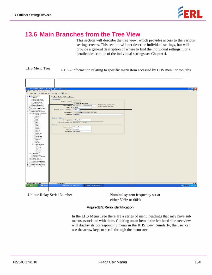
13. Offliner Setting Software
F295-03-17R1.10 F-PRO User Manual 13-8
13.6 Main Branches from the Tree View
This section will describe the tree view, which provides access to the various setting screens. This section will not describe individual settings, but will provide a general description of where to find the individual settings. For a detailed description of the individual settings see Chapter 4.
Figure 13.5: Relay identification
In the LHS Menu Tree there are a series of menu headings that may have sub menus associated with them. Clicking on an item in the left hand side tree view will display its corresponding menu in the RHS view. Similarly, the user can use the arrow keys to scroll through the menu tree.
LHS Menu Tree RHS – information relating to specific menu item accessed by LHS menu or top tabs
Unique Relay Serial Number Nominal system frequency set at either 50Hz or 60Hz

13. Offliner Setting Software
13-9 F-PRO User Manual F295-02-17R1.00
Identification
The first screen presents all the menu items in the left menu tree. Access the menu items by clicking the tabs at the top of the screen or the item on the leftmenu tree.
Table 13.3: Relay Identification
Relay Identification
Identification
Settings Version Indicates the settings version number, fixed.
Ignore Serial Number Bypass serial number check, if enabled.
Serial Number Available at the back of each relay.
Relay ID User-defined up to 16 characters.
Nominal System Frequency 60 Hz or 50 Hz
Comments User-defined up to 78 characters.
Setting Software
Setting Name User-defined up to 16 characters.
Date Created/Modified Indicates the last time settings were entered.
Station
Station Name User-defined up to 16 characters.
Location User-defined up to 16 characters.
Bay Name User-defined up to 16 characters.
Important Note
Nominal CT Sec. Current can be set to either 5 A or 1 A. Nominal System Frequency can be set to either 60 Hz or 50 Hz. Ensure setting selection matches that of target F-PRO
The serial number of the relay must match the one in the setting file, or the setting will be rejected by the relay. This feature ensures that the correct setting file is applied to the right relay.
Choose to ignore the serial number enforcement in the identification screen by checking the Ignore Serial Number check box. The relay only checks for proper relay type and setting version if the ignore serial number has been chosen, requires relay firmware version 1.0 or greater.

13. Offliner Setting Software
F295-03-17R1.10 F-PRO User Manual 13-10
External Inputs
Figure 13.6: External Inputs
The External Inputs screen allows you to define meaningful names for four external inputs.
Table 13.4: External Input Names
1 to 4 User-defined

13. Offliner Setting Software
13-11 F-PRO User Manual F295-03-17R1.10
Output Contacts
Figure 13.7: Output Contacts
The Output Contact Names screen allows you to define meaningful names to the 8 output contacts.
Table 13.5: Output Contact Names
Outputs 1 to 8 User-defined

13. Offliner Setting Software
F295-03-17R1.10 F-PRO User Manual 13-12
Virtual Inputs
Figure 13.8: Virtual Inputs
Table 13.6: Virtual Inputs
Virtual Inputs 1 to 30 User-defined
The relay can control its internal functions and connected devices both locally and remotely. Thirty general purpose logic points are accessible via IEC 103 and the terminal UI. The 30 virtual inputs are individually controlled and include a set, reset and pulse function. The latch state is retained during setting changes and relay power down conditions. The 30 virtual inputs conform to IEC 103 standards. Use the IEC 103 functions such as SBO (Select Before Operate), Direct Operate, or Direct Operate with no acknowledge to control virtual inputs.
Use virtual inputs to:
• Control circuit breakers
• Enable or disable reclosing
• Enable or disable under-frequency load shedding
• Change setting groups
• Provide interlocking between local/remote supervisory control

13. Offliner Setting Software
13-13 F-PRO User Manual F295-03-17R1.10
Setting Groups
Figure 13.9: Setting Groups
The Setting Group Names screen allows you to define meaningful names to the 4 setting groups.
Table 13.7: Setting Groups
Setting Groups 1 to 4 User-defined

13. Offliner Setting Software
F295-03-17R1.10 F-PRO User Manual 13-14
System Parameters
Figure 13.10: System Parameters CT Turns Ratio and PT Turns Ratio
The CT and PT ratios are specified for the analog inputs. All CT and PT ratios are specified with a ratio relative to one (i.e. X amps to 1A and X volts to 1V). The CT secondary current can be chosen as 1A or 5A and the VT secondary connection can be chosen as Phase to Neutral or Phase to Phase. The relay internally summates the three phase currents for the neutral current measurement
Table 13.8: System Parameters
CT Configuration
Phase CT Sec. Current 1A/ 5A
Phase CT ratio 1.0 to 30000.0
VT Configuration
Phase VT Sec. Voltage 40.0 to 160.0 V
Phase VT ratio 1.0 to 10000.0
Phase VT sec. Connection Ph-N/Ph-Ph

13. Offliner Setting Software
13-15 F-PRO User Manual F295-03-17R1.10
Record Length
Figure 13.11: Record Length
The relay has recording and logging functions to analyze faults and to review the operation of the overall protection scheme. This item identifies the amount of time for which each fault is recorded. The prefault time is can be varied from 5-25 cycles.
Table 13.9: Record Length
Fault Record Length 1 to 20 seconds
Pre-trigger 0.10 to 0.50 seconds

13. Offliner Setting Software
F295-03-17R1.10 F-PRO User Manual 13-16
SCADA Communication
Figure 1312 SCADA communication

13. Offliner Setting Software
13-17 F-PRO User Manual F295-03-17R1.10
SCADA Summary
Figure 13.13 SCADA summary
The relay address can be set from 1 to 254 for serial mode of communication either Modbus RTU / Modbus ASCII / IEC103 Slave and also possible to set baud rate & parity. The relay IP address can be set for the purpose of relay configuration purpose as well as IEC61850 communication (SCADA).

13. Offliner Setting Software
F295-03-17R1.10 F-PRO User Manual 13-18
Setting Groups
Figure 13.14: Setting Groups Comments
The relay has four setting groups (1 to 4). You can change all relay setting parameters except the physical connections such as input or output parameters in each setting group. Use any one of the 4 available Group change inputs per group. Logic Statements per setting group to perform Setting Group changes.

13. Offliner Setting Software
13-19 F-PRO User Manual F295-03-17R1.10
Protection Functions
For detailed descriptions of the protection functions see “Protection Functions and Specifications” on page 11-1.
Figure 13.15: Protection Functions

13. Offliner Setting Software
F295-03-17R1.10 F-PRO User Manual 13-20
ProLogic
Figure 13.16: ProLogic
Apply ProLogic to multiple inputs to create an output based on qualified inputs. ProLogic enables up to 20 ProLogic control statements and programs those logics to output contacts. You can name the function being created and set a pickup and dropout delay. Start with input A by selecting any of the relay functions using the list for up to 5 possible inputs. Put these inputs into AND/ OR, NAND/NOR, XOR/NXOR and LATCH logic by clicking on the gate. Invert the input by clicking on the input line.
The output of ProLogic 1 can be nested into ProLogic 2 and so on. If desired, you can illuminate the front target LED on operation of this function by disabling this feature in output matrix. The operations of the ProLogic statements are logged on the events listing. The status of the Prologic can be seen from the record graph by selecting the recorder in the output matrix.

13. Offliner Setting Software
13-21 F-PRO User Manual F295-03-17R1.10
Output Matrix
Figure 13.17: Output Matrix 1
The output contact matrix determines which function initiates which output contact of the relay. All output relays have a fixed 0.1 second stretch time. Functions can also initiate fault recording, recloser blocking, recloser initiation and/or breaker failure initiation.
For a particular function to operate correctly, it must be enabled and must also have its logic output assigned to at least one output contact if it is involved in a tripping function.
Print the entire output matrix by selecting File>Print Summary. This printout is produced on two pages.

`
13. Offliner Setting Software
F295-03-17R1.10 F-PRO User Manual 13-22
Relay Reset The output contact (Relay Output) can be configured as either self reset or hand reset
Self Reset: If Relay reset is configured as Self reset, the relay Output Contact will reset as and when the respective configured Logic Output resets. (Configured in Relay Output Matrix)
Hand Reset: If Relay reset is configured as hand reset, though the configured Logic output resets. The Relay Output contact will not resets on its own, reset button needs to be pressed or respective Configured External Input has to be made High(Configured in Input Matrix) to make the Output Contact Low.
Figure 13.18: Relay Reset

`
13. Offliner Setting Software
13-23 F-PRO User Manual F295-03-17R1.10
Target LED Reset The LEDs can be configured as either self reset or hand reset.
Self Reset: If LED is configured as Self reset, the LED will reset as and when the respective configured Logic Output resets. (Configured in LED Output Matrix)
Hand Reset: If LED is configured as hand reset, Though the configured Logic output resets. The LED will not resets on its own, reset button needs to be pressed or respective Configured External Input has to be made High(Configured in Input Matrix) to make the LED Low.
Figure 13.19: Target LED Reset

13. Offliner Setting Software
F295-03-17R1.10 F-PRO User Manual 13-24
Input Matrix External Input(Static Input) can be configured to Block Protection function, Reset LED and Relay Output Contact(for Hand reset) and to change Setting Group.
Figure 13.20: Input matrix

13. Offliner Setting Software
13-25 F-PRO User Manual F295-03-17R1.10
Settings Summary
Figure13.21: Settings Summary
Select Settings Summary to view and print the relay settings in text form. For details see “IED Settings and Ranges” in Appendix B. Print the entire Settings Summary by selecting File>Print Summary.

13. Offliner Setting Software
F295-03-17R1.10 F-PRO User Manual 13-26
13.7 Settings from a Record The settings on the relay at the time of a recording are included in every record and can be viewed through the Record Base View analysis software. While viewing a recording in Record Base View, select the View Setting button to display the settings. Record Base View will automatically launch F-PRO Offliner to display the settings in summary form.
If the record contains Setting Groups, the Offliner displays all Setting Groups in the summary. Bold text in the tree view indicates an active Setting Group (the Setting Group used at the time the record was captured). The setting summary is read-only. To edit the setting file associated with the summary, you must use File/Save As to save the summary to a file. Then close the summary screen and open the setting file for editing.
Fig 13.22: Setting Summary

14-1 F-PRO User Manual F295-03-17R1.10
14 Installation 14.1 Introduction
This section details the installation of the F -PRO relay. The section covers the physical mounting, AC and DC wiring and the Communication wiring.
14.2 Physical Mounting
Standard E6
The relay is 159 mm high and approximately 216.5mm deep. The standard relay is designed for a 150 mm width. A complete mechanical drawing is shown, for details see “Mechanical Drawings” in Appendix G
To install the relay the following is needed:
• E6 cutout (159*150 mm)
• M4 screws & Nuts
14.3 AC and DC Wiring
For details see “AC Schematic Drawing” in Appendix H and “DC Schematic Drawing” in Appendix I.
14.4 Communication Wiring
EIA-485 RJ-45 USB
IRIG-B Wiring
The relay’s serial port (Com port-2) is a EIA RS-485 Data Communications Equipment (DCE) device. This allows them to be connected directly to other relays in parallel and communicated to a PC serial port with a standard straight-through male-to-female serial cable with RS485 to RS232 convertor. RS 485 cable can work for maximum 1.2kM with single IED . Shielded cable is recommended, for pin -out see “Communication Port Details” on page 9-10. There is one rear100BASE-T Ethernet Port 120 with RJ-45 receptacle. Use CAT5 or CAT5e straight. The re ar Ethernet Port 120 may also be configured as a 100BASE- Fx optical port. The maximum distance that cable support is 100meters (328 feet) Com Port 1 on the fr ont panel is a standard USB-B connector. This port is the Maintenance port of the relay. This is a U SB 2.0 Full Speed interface and can be connected to a PC w ith a standard USB peripheral cable (A style to B style). IRIG-B on the rear panel accepts both modulated and unmodulated IRIG -B standard time signals with or without the IEEE 1344 extensions. T he IRIG-B connector on the back of the relay is BNC type.

F295-03-17R1.10 F-PRO User Manual Appendix A-1
15 Appendix A IED Specifications
F-PRO , Model 295 Specifications
Item Quantity/Specs Note
General:
Nominal Frequency 50 or 60 Hz
Operate Time less than 30ms
Including output relay operation
Memory Settings and records are stored in non-volatile memory
Records are stored in a circular buffer
Power Supply 19-155Vdc, 80-350Vdc, 90 – 240 Vac Power Consumption: 5 – 6 VA (ac) 4.5 – 5 W (dc)
Protection Functions:
IEEE Function 27/59DT1 to 6, 27/59IT1 to 2,24DT1 to 2, 24IT, 47DT1 to 2, 47IT, 59NDT1 to 2, 59NIT, 59GDT1 to 2, 59GIT, 81U/01 to 8, 81R1 to 4, 25/27/29, 64/50SEF-1 to 2, 64/51SEF1 to 2, 60VTS, THD-1 to 2, 74TCS-1 to 2
1 x 3-phase current inputs 1 x 3-phase voltage input f or direction
ProLogic 20 statements per setting group 5 inputs per ProLogicTM statement, /statement
Setting Groups 4
Recording:
Transient (Fault) 32 s/c oscillography of all analog and exte rnal input digital channels
User-configurable 1 to 20 seconds Record length and 0.1 to 0.5 pre-fault length
Events 1000 events circular log with 1ms resolution I*I*t: trigger by user defined event an d/or trip
A compressed event record can be created 1000 events with manual trigger.
A/D Resolution
6 bits, 65536 counts full scale peak-peak
Record Capacity 20 records of transient and optionally event records.

Appendix A-2 F-PRO User Manual F295-03-17R1.10
F-PRO Model Specifications
Input & Output:
Analog Voltage Inputs 1 set of 3-phase voltage inputs (3 voltage channels), 1 voltage input to measure neutral voltage and 1 voltage input to synchronization
Nominal Voltage – across input channel Full Scale/Continuous Maximum full-scale rating Thermal rating Burden
Vn=63.5Vrms(110Vrms L-L) 2xVn=127Vrms(230Vrms L-L) 4xVn = 254Vrms(440Vrms L-L) or 3 Seconds 3xVn = 190Vrms(330Vrms L-L) for 10 seconds <0.03 VA @ Vn
1 current input to measure SEF
Nominal Current Full Scale/Continuous Maximum full-scale rating Thermal rating Burden
In = 1 Amp or 5 Amps 3x In = 3 Amps or 15 Amps 30x In for 1 second symmetrical 300 Amps for 1 second <0.25 VA @ 5 Amps
Amplitude measurement accuracy +/-1% for 45 to 55Hz +/-1% for 55 to 65Hz
Analog Sampling Rate 32 samples/cycle for recording 8 samples/cycle for protection
Records upto 8th harmonic
External Inputs (digital) 4 isolated inputs Optional 24/30, 48/50, 110/125, 220/250 Vdc nominal, externally wetted
Isolation 2 KV optical isolation
External Input Turn-on Voltage 24Vdc range = 14 to 20
48Vdc range = 24 to 40
110Vdc range = 55 to 90
220Vdc range = 110 to 180
Output Relays (contacts) 8 programmable outputs (6NO +2CO) Externally wetted Make: 30 A as per IEEE C37.90 Carry: 8 A Break: 0.9 A at 125 Vdc resistive
0.35 A at 250 Vdc resistive
Virtual Inputs 30 Virtual Inputs
Interface & Communication:
Front Display 2 line 16 character Alphanumeric LCD
Front Panel Indicators 8 LEDs: 7 programmable, 1 fixed
Front User Interface USB port Full Speed USB 2.0 480Mbps
Rear User Interface LAN Port 1: 100BASE Copper
one Serial RS-485 port (2400bps to 57600bps)
Copper: RJ-45, 100BASE-T
Com port
SCADA Interface IEC61850 (Ethernet) 100 Mbps or Modbus (RS-485) or IEC 60870-5-103(RS-485)
Rear port
Time Sync IRIG-B, BNC connector
Modulated or unmodulated

F295-03-17R1.10 F-PRO User Manual Appendix A-3
Self Checking/Relay Inoperative 2CO contact configurable Closed NC when relay inoperative
F-PRO Model Specifications
Overall F-PRO Accuracies
Current ±2.5% of inputs from 0.1 to 1.0 x nominal current (In)
±1.0% of inputs from 1.0 to 4.0 x nominal current (In)
Voltage ±1.0% of input of nominal voltage (Vn)
Timers ±2.5 % of set value plus 1.00 to 1.50 cycles of inherent delay
Inverse Overcurrent Timers ±2.5% or ±1 cycle of selected curve
Definite Overcurrent Timers ±2.5% or ±1 cycle non-directional
±2.5% or ±1.5 cycle directional
F-PRO Model Specifications
Physical:
Weight 4.55 Kg
Dimensions
E6 case : 17.7cm High x 15.5cm W ide x 24.75cm Depth
Time Synchronization and Accuracy
External Time Source Synchronized using I RIG-B input (modulated or unmodulated) 1PPM
In the absence of an external time source, the relay maintains time with a maximum 20ppm at a constant temperature of 25C. The relay can detect loss of re-establishment of external time source and aut omatically switch between internal and external time.

Appendix A-4 F-PRO User Manual F295-03-17R1.10
F-PRO Model Specifications
Environmental:
Ambient Temperature Range -40°C to 85°C for 16 hours -40°C to 70°C continuous
IEC 60068-2-1/IEC 60068-2-2 LCD contrast impaired for temperatures below -20°C and above 70° C Humidity Up to 95% without condensation IEC 60068-2-30
Insulation Test (Hi-Pot)
Power supply, analog inputs, external inputs, output contacts – 2 kVrms, 50/60 Hz, 1 minute
IEC 60255-5, ANSI/IEEE C37.90
Electrical Fast Transient Tested to level 4 - 4.0 kV 2.5/5 kHz on Power and I/O lines
ANSI/IEEE C37.90.1, IEC/EN 60255- 22-4, IEC 61000-4-4
Oscillatory Transient Test level = 2.5kV ANSI/IEEE C37.90.1, IEC/EN 60255- 22-1, IEC61000-4-12 Level 3
RFI Susceptibility 10 V/m modulated, 35 V/m unmodulated ANSI/IEEE C37.90.2, IEC 60255-22-3, IEC 61000-4-3 Level 3
Conducted RF Immunity 150 kHz to 80 MHz IEC 60255-22-6 / IEC 61000-4-6 Level 3
Shock and Bump 5 g and 15 g IEC 60255-21-2, IEC/EN 60068-2-27: Class 1
Sinusoidal Vibration 10 Hz to 150 Hz, 1.0 octave/min, 40 sweeps IEC/EN 60255-21-1, IEC/EN 60068-26, Class 1
Voltage Interruptions 200 ms interrupt IEC 60255-11 / IEC 61000-4-11
Detailed Environmental Tests
Test Description
Test Level Type Test
Test Points
CISPR11, ClassA RF emissions Enclosure ports Class A: 30 - 1000 MHz
Conducted emissions ac/dc power ports Class A: 0.15 - 30 MHz
IEC/EN 61000-3-2 Power line harmonics ac power port Class D: max.1.08, 2.3, 0.431.14, 0.3, 0.77, 0.23 A.... for 2nd to nth har- monic
IEC/EN 61000-3-3 Power line fluctuations ac power port THD/ 3%; Pst <1., Plt < 0.65
dc power port N/A
IEC/EN 61000-4-2 Electrostatic Discharge Immunity
Enclosure contact +/- 8 kV
Enclosure air +/- 15 kV
IEC/EN 61000-4-3 Radiated RFI Enclosure ports 10 V/m: 80 - 1000 MHz
IEC/EN 60255-22-3
IEEE C37.90.2 Radiated RFI Enclosure ports 35 V/m: 25 - 1000 MHz

F295-03-17R1.10 F-PRO User Manual Appendix A-5
IEC/EN 61000-4-4 Electrical fast transient / Burst Immunity
Signal ports +/- 4 kV @2.5 kHz
IEC/EN 60255-22-4 ac power port +/- 4 kV
IEEE C37.90.1 dc power port +/- 4 kV Earth ground ports +/- 4 kV
IEC/EN 61000-4-5 Surge Immunity Communication ports +/- 1 kV L-PE
IEC/EN 60255-22-5 Signal ports +/- 4 kV L-PE, +/-2 kV L-L ac power port +/- 4 kV L-PE, +/-2 kV L-L dc power port +/- 2 kV L-PE, +/-1 kV L-L
IEC/EN 61000-4-6 Induced (conducted) RFI Signal ports 10 Vrms: 0.150 - 80 MHz IEC/EN 60255-22-6 ac power port 10 Vrms: 0.150 - 80 MHz dc power port 10 Vrms: 0.150 - 80 MHz Earth ground ports 10 Vrms: 0.150 - 80 MHz IEC/EN 60255-22-7 Power frequency Binary input ports: Class A Differential = 150 Vrms Common = 300 Vrms IEC/EN 61000-4-8 Magnetic leld Enclosure ports 40 A/m continuous, 1000 A/m for 1 s IEC 60255-11 Voltage dips & interrupts dc power port 100% reduction for up to 25 ms IEC/EN 61000-4-12 Damped oscillatory Communication ports 1.0 kV Common, 0 kV Diff IEC/EN 60255-22-1 Signal ports 2.5 kV Common, 1 kV Diff ac power port 2.5 kV Common, 1 kV Diff dc power port 2.5 kV Common, 1 kV Diff IEEE C37.90.1 Oscillatory Signal ports 2.5 kV Common, 0 kV Diff ac power port 2.5 kV Common, 0 kV Diff dc power port 2.5 kV Common, 0 kV Diff IEC/EN 61000-4-16 Mains frequency voltage Signal ports 30 V continuous, 300 V for 1s ac power port 30 V continuous, 300 V for 1s IEC/EN 61000-4-17 Ripple on dc power supply dc power port 12%
Note: The F-PRO is available with1 or 5 amp current input.

Appendix A-6 F-PRO User Manual F295-03-17R1.10
15.1 IDMTL Element Operating Time Curves
Figure A.1: Represents the operating curve for IDMTL IEC very inverse curve.
Figure A.2: Represents the operating curve IDMTL IEC Standard inverse curve 3.

F295-03-17R1.10 F-PRO User Manual Appendix A-7
Figure A.3: Represents the operating curve for IDMTL IEC Standard inverse curve 1.
Figure A.4: Represents the operating curve for IDMTL IEC Long inverse curve

Appendix A-8 F-PRO User Manual F295-03-17R1.10
Figure A.5: Represents the operating curve for IDMTL IEC Extremely inverse curve.
Figure A.6: Represents the operating curve for IDMTL IEEE Moderately inverse curve.

F295-03-17R1.10 F-PRO User Manual Appendix A-9
Figure A.7: Represents the operating curve for IDMTL IEEE very inverse curve.
Figure A.8: Represents the operating curve for IDMTL IEEE Extremely inverse curve.

Appendix B-1 F-PRO User Manual F295-03-17R1.10
16. Appendix B IED Settings and Ranges
16 Appendix B IED Settings and Ranges
When a setting has been completed in the F -PRO Offliner Settings software, it can be printed along with the ranges available for these settings. This is a view only option, that is, if you want to change settings you must go back i n to the settings portion dealing with that setting to make changes. The summary is however, a quick way of having a look at all the settings in a very compact form.
The top part of the settings summary identifies the date that the settings were done, the relay identification, the station that the relay is applied and t he location.
The setting summa ry provides a list of all the current and voltage analog input quantity names used for line protection and used for recording. External Inputs and Output contact names are also identified on this summary.
Name Symbol/Value Unit Range
Relay Identification
Settings Version 1
Ignore Serial Number Yes
Serial Number FPRO-295-XX0000000
Relay ID RelayID
Nominal System Frequency 50 Hz
Standard I/O 4 External Inputs and 8 Output Contacts
Comments Comments
Setting Name Settings Name
Date Created/Modified 2016-09-28 12:05:40
Station Name Station Name
Location Location
Bay Name Bay Name
External Input Names
EI 1 EI 1
EI 2 EI 2
EI 3 EI 3
EI 4 EI 4
Output Contact Names
Output 1 RL 1
Output 2 RL 2
Output 3 RL 3
Output 4 RL 4
Output 5 RL 5
Output 6 RL 6
Output 7 RL 7
Output 8 RL 8

16. Appendix B IED Settings and Ranges
F295-03-17R1.10 F-PRO User Manual Appendix B-2
Name Symbol/Value Unit Range
Virtual Input Names
VI 1 VI 1
VI 2 VI 2
VI 3 VI 3
VI 4 VI 4
VI 5 VI 5
VI 6 VI 6
VI 7 VI 7
VI 8 VI 8
VI 9 VI 9
VI 10 VI 10
VI 11 VI 11
VI 12 VI 12
VI 13 VI 13
VI 14 VI 14
VI 15 VI 15
VI 16 VI 16
VI 17 VI 17
VI 18 VI 18
VI 19 VI 19
VI 20 VI 20
VI 21 VI 21
VI 22 VI 22
VI 23 VI 23
VI 24 VI 24
VI 25 VI 25
VI 26 VI 26
VI 27 VI 27
VI 28 VI 28
VI 29 VI 29
VI 30 VI 30
Setting Group Names
Setting Group 1 SG 1
Setting Group 2 SG 2
Setting Group 3 SG 3
Setting Group 4 SG 4

16. Appendix B IED Settings and Ranges
Appendix B-3 F-PRO User Manual F295-03-17R1.10
Name Symbol/Value Unit Range
System Parameters VT Configuration
Phase VT Sec.voltage 63.5 V 40.0 to 160.0
Phase VT Ratio 100.0 - 1.0 to 10000.0
Neutral VT Sec.voltage 63.5 V 40.0 to 160.0
Neutral VT Ratio 100.0 - 1.0 to 10000.0
Voltage Compensation 0.0 V 0.0 to 15.0
Sync VT Sec.voltage 63.5 V 40.0 to 160.0
Sync VT Ratio 100.0 - 1.0 to 10000.0
CT Configuration
SEF CT Sec.current 1A A
SEF CT Ratio 100.0 - 1.0 to 30000.0
Disturbance Record Record Length 1 s 1 to 20
Pre Trigger 0.25 s 0.10 to 0.50
SCADA Communication Relay Address 0 1 to 254
Mode
Serial Modbus RTU
Modbus ASCII/Modbus RTU / IEC103 Slave
Baud Rate 9600 2400 - 57600 Parity None Odd/Even/None
Network IP Address 192.168.0.63
Subnet Mask 255.255.255.0
Gateway 192.168.0.1
Setting Group 1 [SG 1] Setting Group Comments: No Comments Protection Summary
27/59DT-1 Disabled 27/59DT-2 Disabled 27/59DT-3 Disabled 27/59DT-4 Disabled 27/59DT-5 Disabled 27/59DT-6 Disabled 27/59IT-1 Disabled 27/59IT-2 Disabled 24DT-1 Disabled

16. Appendix B IED Settings and Ranges
F295-03-17R1.10 F-PRO User Manual Appendix B-4
Name Symbol/Value Unit Range
24DT-2 Disabled 24IT Disabled 47DT-1 Disabled 47DT-2 Disabled 47IT Disabled 59NDT-1 Disabled 59NDT-2 Disabled 59NIT Disabled 59GDT-1 Disabled 59GDT-2 Disabled 59GIT Disabled 81U/O-1 Disabled 81U/O-2 Disabled 81U/O-3 Disabled 81U/O-4 Disabled 81U/O-5 Disabled 81U/O-6 Disabled 81U/O-7 Disabled 81U/O-8 Disabled 81R-1 Disabled 81R-2 Disabled 81R-3 Disabled 81R-4 Disabled 25/27/59 Disabled 64/50SEF-1 Disabled 64/50SEF-2 Disabled 64/51SEF-1 Enabled 64/51SEF-2 Enabled 60VTS Enabled THD-1 Enabled THD-2 Enabled 74TCS-1 Disabled 74TCS-2 Disabled U/V Enabled O/V Enabled U/F Enabled O/F Enabled S/I Enabled

16. Appendix B IED Settings and Ranges
Appendix B-5 F-PRO User Manual F295-03-17R1.10
Name Symbol/Value Unit Range
27/59DT - Phase Definite Time Under/Over Voltage
27/59DT-1 Disabled
Function Selection UV
Measurement Input Fundamental
Input Type Ph-N
Output Gate AND
Pickup V 51.0 V 3.0 to 250.0
Hysteresis 1 % 1 to 80
Pick DTL Delay 0.20 s 0.00 to 999.99
Reset DTL Delay 0.00 s 0.00 to 999.99
VTS Blocking Enable
27/59DT-2 Disabled
Function Selection UV
Measurement Input Fundamental
Input Type Ph-N
Output Gate AND
Pickup V 51.0 V 3.0 to 250.0
Hysteresis 1 % 1 to 80
Pick DTL Delay 0.20 s 0.00 to 999.99
Reset DTL Delay 0.00 s 0.00 to 999.99
VTS Blocking Enable
27/59DT-3 Disabled
Function Selection UV
Measurement Input Fundamental
Input Type Ph-N
Output Gate AND
Pickup V 51.0 V 3.0 to 250.0
Hysteresis 1 % 1 to 80
Pick DTL Delay 0.20 s 0.00 to 999.99

16. Appendix B IED Settings and Ranges
F295-03-17R1.10 F-PRO User Manual Appendix B-7
Name Symbol/Value Unit Range
Reset DTL Delay 0.00 s 0.00 to 999.99
VTS Blocking Enable
27/59DT-4 Disabled
Function Selection UV
Measurement Input Fundamental
Input Type Ph-N
Output Gate AND
Pickup V 51.0 V 3.0 to 250.0
Hysteresis 1 % 1 to 80
Pick DTL Delay 0.20 s 0.00 to 999.99
Reset DTL Delay 0.00 s 0.00 to 999.99
VTS Blocking Enable
27/59DT-5 Disabled
Function Selection UV
Measurement Input Fundamental
Input Type Ph-N
Output Gate AND
Pickup V 51.0 V 3.0 to 250.0
Hysteresis 1 % 1 to 80
Pick DTL Delay 0.20 s 0.00 to 999.99
Reset DTL Delay 0.00 s 0.00 to 999.99
VTS Blocking Enable
27/59DT-6 Disabled
Function Selection UV
Measurement Input Fundamental
Input Type Ph-N
Output Gate AND
Pickup V 51.0 V 3.0 to 250.0

16. Appendix B IED Settings and Ranges
F295-03-17R1.10 F-PRO User Manual Appendix B-7
Name Symbol/Value Unit Range
Hysteresis 1 % 1 to 80
Pick DTL Delay 0.20 s 0.00 to 999.99
Reset DTL Delay 0.00 s 0.00 to 999.99
VTS Blocking Enable
27/59IT - Phase Inverse Time Under/Over Voltage
27/59IT-1 Disabled
Function Selection UV
Measurement Input Fundamental
Input Type Ph-N
Output Gate AND
Pickup V 55.0 V 3.0 to 250.0
Hysteresis 1 % 1 to 80
Curve Type IEC Standard Inverse
TMS 1.00 - 0.01 to 10.00
Pick DTL Delay 10.00 s 0.00 to 999.99
Reset DTL Delay 0.00 s 0.00 to 999.99
A 1.0 - 0.1 to 50.0
B 0.0 - 0.0 to 10.0
p 1.0 - 0.1 to 10.0
VTS Blocking Enable
27/59IT-2 Disabled
Function Selection UV
Measurement Input Fundamental
Input Type Ph-N
Output Gate AND
Pickup V 55.0 V 3.0 to 250.0
Hysteresis 1 % 1 to 80
Curve Type IEC Standard Inverse

16. Appendix B IED Settings and Ranges
F295-03-17R1.10 F-PRO User Manual Appendix B-8
Name Symbol/Value Unit Range
TMS 1.00 - 0.01 to 10.00
Pick DTL Delay 10.00 s 0.00 to 999.99
Reset DTL Delay 0.00 s 0.00 to 999.99
A 1.0 - 0.1 to 50.0
B 0.0 - 0.0 to 10.0
p 1.0 - 0.1 to 10.0
VTS Blocking Enable
24DT - Definite Time Overflux
24DT-1 Disabled
Measurement Input Fundamental
Input Type Ph-N
Output Gate AND
Pickup V/F 1.10 pu 1.00 to 3.00
Hysteresis 1 % 1 to 80
Pick DTL Delay 0.20 s 0.00 to 999.99
Reset DTL Delay 0.00 s 0.00 to 999.99
VTS Blocking Enable
24DT-2 Disabled
Measurement Input Fundamental
Input Type Ph-N
Output Gate AND
Pickup V/F 1.10 pu 1.00 to 3.00
Hysteresis 1 % 1 to 80
Pick DTL Delay 0.20 s 0.00 to 999.99
Reset DTL Delay 0.00 s 0.00 to 999.99
VTS Blocking Enable
24IT - Inverse Time Overflux
24IT Disabled
Measurement Input Fundamental
Input Type Ph-N

16. Appendix B IED Settings and Ranges
Appendix B-9 F-PRO User Manual F295-03-17R1.10
Name Symbol/Value Unit Range
Output Gate AND
Pickup V/F 1.10 pu 1.00 to 1.50/2.00/3.00
Hysteresis 1 % 1 to 80
Curve Type IEC Extremely Inverse-1
TMS 1.00 - 0.01 to 10.00
Pickup DTL Delay 10.00 s 0.00 to 999.99
Reset Delay DTL Reset DTL Delay 0.00 s 0.00 to 99.90
Constant A: 9.50 - -
Constant B: 1.00 - 0.01 to 10.00
Constant C: 0.000 - -
Constant K: 0.00 - -
Inverse K: 0.10 - 0.01 to 99.90
X1 1.10 pu 1.00 to 3.00 X2 1.15 pu 1.00 to 3.00
X3 1.20 pu 1.00 to 3.00
X4 1.25 pu 1.00 to 3.00
X5 1.30 pu 1.00 to 3.00
X6 1.35 pu 1.00 to 3.00
X7 1.40 pu 1.00 to 3.00
Y1 70.00 s 0.05 to 9999.99
Y2 60.00 s 0.05 to 9999.99
Y3 50.00 s 0.05 to 9999.99
Y4 40.00 s 0.05 to 9999.99
Y5 30.00 s 0.05 to 9999.99
Y6 20.00 s 0.05 to 9999.99
Y7 10.00 s 0.05 to 9999.99
VTS Blocking Enable 47DT - Negative Sequence Definite Time Over Voltage 47DT-1 Disabled
Measurement Input Fundamental Pickup V2 30.0 V 1.0 to 150.0
Hysteresis 1 % 1 to 80
Pick DTL Delay 0.20 s 0.00 to 999.99
Reset DTL Delay 0.00 s 0.00 to 999.99
VTS Blocking Enable

16. Appendix B IED Settings and Ranges
F295-03-17R1.10 F-PRO User Manual Appendix B-10
Name Symbol/Value Unit Range
47DT-2 Disabled
Measurement Input Fundamental
Pickup V2 30.0 V 1.0 to 150.0
Hysteresis 1 % 1 to 80
Pick DTL Delay 0.20 s 0.00 to 999.99
Reset DTL Delay 0.00 s 0.00 to 999.99
VTS Blocking Enable
47IT - Negative Sequence Inverse Time Over Voltage
47IT Disabled
Measurement Input Fundamental
Pickup V2 25.0 V 1.0 to 150.0
Hysteresis 1 % 1 to 80
Curve Type IEC Standard Inverse
TMS 1.00 - 0.01 to 10.00
Pick DTL Delay 10.00 s 0.00 to 999.99
Reset DTL Delay 0.00 s 0.00 to 999.99
A 1.0 - 0.1 to 50.0
B 0.0 - 0.0 to 10.0
p 1.0 - 0.1 to 10.0
VTS Blocking Enable
59NDT - Derived Residual Definite Time Over Voltage
59NDT-1 Disabled
Measurement Input Fundamental
Pickup VN 10.0 V 1.0 to 250.0
Hysteresis 1 % 1 to 80
Pick DTL Delay 0.20 s 0.00 to 999.99
Reset DTL Delay 0.00 s 0.00 to 999.99
VTS Blocking Enable

16. Appendix B IED Settings and Ranges
Appendix B-11 F-PRO User Manual F295-03-17R1.10
Name
Symbol/Value
Unit
Range
59NDT-2 Disabled
Measurement Input Fundamental
Pickup VN 10.0 V 1.0 to 250.0
Hysteresis 1 % 1 to 80
Pick DTL Delay 0.20 s 0.00 to 999.99
Reset DTL Delay 0.00 s 0.00 to 999.99
VTS Blocking Enable
59NIT - Derived Residual Inverse Time Over Voltage
59NIT Disabled
Measurement Input Fundamental
Pickup VN 7.0 V 1.0 to 250.0
Hysteresis 1 % 1 to 80
Curve Type IEC Standard Inverse
TMS 1.00 - 0.01 to 10.00
Pick DTL Delay 10.00 s 0.00 to 999.99
Reset DTL Delay 0.00 s 0.00 to 999.99
A 1.0 - 0.1 to 50.0
B 0.0 - 0.0 to 10.0
p 1.0 - 0.1 to 10.0
VTS Blocking Enable
59GDT - Measured Residual Definite Time Over Voltage
59GDT-1 Disabled
Measurement Input Fundamental
Voltage Compensation 0.0 V 0.0 to 15.0
Pickup VG 10.0 V 1.0 to 250.0
Hysteresis 1 % 1 to 80
Pick DTL Delay 0.20 s 0.00 to 999.99
Reset DTL Delay 0.00 s 0.00 to 999.99

16. Appendix B IED Settings and Ranges
F295-03-17R1.10 F-PRO User Manual Appendix B-12
Name Symbol/Value Unit Range
59GDT-2 Disabled
Measurement Input Fundamental
Voltage Compensation 0.0 V 0.0 to 15.0
Pickup VG 10.0 V 1.0 to 250.0
Hysteresis 1 % 1 to 80
Pick DTL Delay 0.20 s 0.00 to 999.99
Reset DTL Delay 0.00 s 0.00 to 999.99
59GIT - Measured Residual Inverse Time Over Voltage
59GIT Disabled
Voltage Compensation 0.0 V 0.0 to 15.0
Measurement Input Fundamental
Pickup VG 66.7 V 1.0 to 250.0
Hysteresis 1 % 1 to 80
Curve Type IEC Standard Inverse
TMS 1.00 - 0.01 to 10.00
Pick DTL Delay 10.00 s 0.00 to 999.99
Reset DTL Delay 0.00 s 0.00 to 999.99
A 1.0 - 0.1 to 50.0
B 0.0 - 0.0 to 10.0
p 1.0 - 0.1 to 10.0
81U/O - Under/Over Frequency
81U/O-1 Disabled
Function Selection UV
Pickup F 49.0 Hz 40.0 to 60.0
Hysteresis 1 % 1 to 80
Pickup Delay 2.00 s 0.00 to 999.99
VTS Blocking Enable
81U/O-2 Disabled
Function Selection UV Pickup F 49.0 Hz 40.0 to 60.0

16. Appendix B IED Settings and Ranges
Appendix B-13 F-PRO User Manual F295-03-17R1.10
Name Symbol/Value Unit Range
Hysteresis 1 % 1 to 80
Pickup Delay 2.00 s 0.00 to 999.99
VTS Blocking Enable
81U/O-3 Disabled
Function Selection UV
Pickup F 49.0 Hz 40.0 to 60.0
Hysteresis 1 % 1 to 80
Pickup Delay 2.00 s 0.00 to 999.99
VTS Blocking Enable
81U/O-4 Disabled
Function Selection UV
Pickup F 49.0 Hz 40.0 to 60.0
Hysteresis 1 % 1 to 80
Pickup Delay 2.00 s 0.00 to 999.99
VTS Blocking Enable
81U/O-5 Disabled
Function Selection UV
Pickup F 49.0 Hz 40.0 to 60.0
Hysteresis 1 % 1 to 80
Pickup Delay 2.00 s 0.00 to 999.99
VTS Blocking Enable
81U/O-6 Disabled
Function Selection UV
Pickup F 49.0 Hz 40.0 to 60.0
Hysteresis 1 % 1 to 80
Pickup Delay 2.00 s 0.00 to 999.99
VTS Blocking Enable

F295-03-17R1.10 F-PRO User Manual Appendix B-14
16. Appendix B IED Settings and Ranges
Name Symbol/Value Unit Range
81U/O-7 Disabled
Function Selection UV
Pickup F 49.0 Hz 40.0 to 60.0
Hysteresis 1 % 1 to 80
Pickup Delay 2.00 s 0.00 to 999.99
VTS Blocking Enable
81U/O-8 Disabled
Function Selection UV
Pickup F 49.0 Hz 40.0 to 60.0
Hysteresis 1 % 1 to 80
Pickup Delay 2.00 s 0.00 to 999.99
VTS Blocking Enable
81R - Rate of Change of Frequency
81R-1 Disabled
Pickup df/dt -0.5 Hz -10.0 to 10.0
Hysteresis 1 % 1 to 80
Pickup Delay 1.00 s 0.00 to 999.99
VTS Blocking Enable
81R-2 Disabled
Pickup df/dt -0.5 Hz -10.0 to 10.0
Hysteresis 1 % 1 to 80
Pickup Delay 1.00 s 0.00 to 999.99
VTS Blocking Enable
81R-3 Disabled
Pickup df/dt -0.5 Hz -10.0 to 10.0
Hysteresis 1 % 1 to 80
Pickup Delay 1.00 s 0.00 to 999.99
VTS Blocking Enable

16. Appendix B IED Settings and Ranges
Appendix B-15 F-PRO User Manual F295-03-17R1.10
Name Symbol/Value Unit Range
81R-4 Disabled
Pickup df/dt -0.5 Hz -10.0 to 10.0
Hysteresis 1 % 1 to 80
Pickup Delay 1.00 s 0.00 to 999.99
VTS Blocking Enable
25/27/59 - Check Synchronization
25/27/59 Disabled
Maximum Voltage 70 V 60 to 138
Minimum Voltage 40 V 40 to 69.9
Angle Difference 20 Deg 1.0 to 50.0
Phase Angle Difference 5 Deg 1.0 to 50.0
PickUp Delay 0.10 s 0.00 to 10.00
Frequency Difference Disabled
Frequency Difference 0.010 Hz 0.010 to 2.000
DMLS Disabled
LMDS Disabled
DMDS Disabled
67SEF-Directional Function for SEF
Characteristic Angle -15 Deg -95 to 95
Minimum Voltage 10.0 V 0.3 to 40.0
Measurement Input VN VTS Blocking Enabled

16. Appendix B IED Settings and Ranges
F295-03-17R1.10 F-PRO User Manual Appendix B-16
Name Symbol/Value Unit Range
64/50SEF - Instantaneous SEF/REF
64/50SEF-1 Disabled
Direction Selection Non-Dir
Measurement Input Fundamental
Pickup ISEF 0.200 A 0.005 to 3.000
Pick Delay 0.00 s 0.00 to 999.99
Current Compensation 0.000 A 0.000 to 0.500
64/50SEF-2 Disabled
Direction Selection Non-Dir
Measurement Input Fundamental
Pickup ISEF 0.200 A 0.005 to 3.000
Pick Delay 0.00 s 0.00 to 999.99
Current Compensation 0.000 A 0.000 to 0.500 64/51SEF - Inverse Time Sensitive / Restricte d Earth Fault
64/51SEF-1 Enabled
Direction Selection Non-Dir
Measurement Input Fundamental
Pickup ISEF 0.200 A 0.005 to 3.000
Curve Type IEC standard inverse-3
TMS 1.00 - 0.01 to 10.00
Pickup DTL Delay 10.00 s 0.00 to 999.99
Reset Delay DTL
Reset DTL Delay 0.0 s 0.0 to 99.9
Reset delay(TR) 13.50 - 0.10 to 150.00
A 0.1400 - 0.0010 to 1000.0000
B 0.0000 - 0.0000 to 10.0000
p 0.02 - 0.01 to 100.00
Current Compensation 0.000 A 0.000 to 0.500

16. Appendix B IED Settings and Ranges
Appendix B-17 F-PRO User Manual F295-03-17R1.10
Name Symbol/Value Unit Range
64/51SEF-2 Enabled
Direction Selection Non-Dir
Measurement Input Fundamental
Pickup ISEF 0.200 A 0.005 to 3.000
Curve Type IEC standard inverse-3
TMS 1.00 - 0.01 to 10.00
Pickup DTL Delay 10.00 s 0.00 to 999.99
Reset Delay DTL
Reset DTL Delay 0.0 s 0.0 to 99.9
Reset delay(TR) 13.50 - 0.10 to 150.00
A 0.1400 - 0.0010 to 1000.0000
B 0.0000 - 0.0000 to 10.0000
p 0.02 - 0.01 to 100.00
Current Compensation 0.000 A 0.000 to 0.500
60VTS - VT Supervision
60VTS Enabled
Pickup VN 33.0 V 1.0 to 40.0
Pickup V3ph 10.0 V 1.0 to 40.0
Pickup Delay 1.00 s 0.10 to 999.99
CB status check Disabled
THD - Total Harmonic Distortion
THD-1 Enabled
Pickup THD-V 3 % 1 to 100
Pickup Delay 5.00 s 0.00 to 999.99
VTS Blocking Enable
THD-2 Enabled Pickup THD-V 3 % 1 to 100
Pickup Delay 5.00 s 0.00 to 999.99
VTS Blocking Enable

16. Appendix B IED Settings and Ranges
F295-03-17R1.10 F-PRO User Manual Appendix B-18
Name Symbol/Value Unit Range
74TCS - Trip Circuit Supervision
74TCS-1[TCS 1] Disabled
Dropoff Delay 0.40 s 0.00 to 9.99
74TCS-2[TCS 2] Disabled
Dropoff Delay 0.40 s 0.00 to 9.99
U/V - Under Voltage Count Alarm
U/V Enabled
Pickup V 40.0 V 1.0 to 220.0
U/V Count 100 - 1 to 1000
Count Accumulation Period 1 days 1 to 31
O/V - Over Voltage Count Alarm
O/V Enabled
Pickup V 70.0 V 1.0 to 220.0
O/V Count 100 - 1 to 1000
Count Accumulation Period 1 days 1 to 31
U/F - Under Frequency Count Alarm
U/F Enabled
Pickup F 49.90 Hz 40.00 to 50.00
U/F Count 100 - 1 to 1000
Count Accumulation Period 1 days 1 to 31
O/F - Over Frequency Count Alarm
O/F Enabled
Pickup F 50.10 Hz 50.00 to 60.00
O/F Count 100 - 1 to 1000
Count Accumulation Period 1 days 1 to 31
S/I - Status Input Count Alarm
S/I Enabled

16. Appendix B IED Settings and Ranges
Appendix B-19 F-PRO User Manual F295-03-17R1.10
Name Symbol/Value Unit Range
Count Input SI4
Pickup Delay 0.10 s 0.00 to 99.99
S/I Count 100 - 1 to 1000
Count Accumulation Period 1 days 1 to 31
PL 1 [ProLogic 1]
ProLogic 1 Disabled
Pickup Delay-Tp 0.00 s 0.00 to 999.00
Dropout Delay-Td 0.00 s 0.00 to 999.00
Operator 1
Input A <Unused = 0>
Operator 2
Input B <Unused = 0>
Operator 3
Input C <Unused = 0>
Operator 4
Input D <Unused = 0>
Operator 5
Input E <Unused = 0>
PL 2 [ProLogic 2]
ProLogic 2 Disabled
Pickup Delay-Tp 0.00 s 0.00 to 999.00
Dropout Delay-Td 0.00 s 0.00 to 999.00
Operator 1
Input A <Unused = 0>
Operator 2 Input B <Unused = 0>
Operator 3

16. Appendix B IED Settings and Ranges
F295-03-17R1.10 F-PRO User Manual Appendix B-20
Name Symbol/Value Unit Range
Input C <Unused = 0>
Operator 4
Input D <Unused = 0>
Operator 5
Input E <Unused = 0>
PL 3 [ProLogic 3]
ProLogic 3 Disabled
Pickup Delay-Tp 0.00 s 0.00 to 999.00
Dropout Delay-Td 0.00 s 0.00 to 999.00
Operator 1
Input A <Unused = 0>
Operator 2
Input B <Unused = 0>
Operator 3
Input C <Unused = 0>
Operator 4
Input D <Unused = 0>
Operator 5
Input E <Unused = 0>
PL 4 [ProLogic 4]
ProLogic 4 Disabled
Pickup Delay-Tp 0.00 s 0.00 to 999.00
Dropout Delay-Td 0.00 s 0.00 to 999.00
Operator 1
Input A <Unused = 0>
Operator 2
Input B <Unused = 0>
Operator 3
Input C <Unused = 0>
Operator 4

F295-03-17R1.10 F-PRO User Manual Appendix B-21
16. Appendix B IED Settings and Ranges
Name Symbol/Value Unit Range
Input D <Unused = 0>
Operator 5
Input E <Unused = 0>
PL 5 [ProLogic 5]
ProLogic 5 Disabled
Pickup Delay-Tp 0.00 s 0.00 to 999.00
Dropout Delay-Td 0.00 s 0.00 to 999.00
Operator 1
Input A <Unused = 0>
Operator 2
Input B <Unused = 0>
Operator 3
Input C <Unused = 0>
Operator 4
Input D <Unused = 0>
Operator 5
Input E <Unused = 0>
PL 6 [ProLogic 6]
ProLogic 6 Disabled
Pickup Delay-Tp 0.00 s 0.00 to 999.00
Dropout Delay-Td 0.00 s 0.00 to 999.00
Operator 1
Input A <Unused = 0>
Operator 2
Input B <Unused = 0>
Operator 3
Input C <Unused = 0>
Operator 4
Input D <Unused = 0>
Operator 5

16. Appendix B IED Settings and Ranges
F295-03-17R1.10 F-PRO User Manual Appendix B-22
Name Symbol/Value Unit Range
Input E <Unused = 0>
PL 7 [ProLogic 7]
ProLogic 7 Disabled
Pickup Delay-Tp 0.00 s 0.00 to 999.00
Dropout Delay-Td 0.00 s 0.00 to 999.00
Operator 1
Input A <Unused = 0>
Operator 2
Input B <Unused = 0>
Operator 3
Input C <Unused = 0>
Operator 4
Input D <Unused = 0>
Operator 5
Input E <Unused = 0>
PL 8 [ProLogic 8]
ProLogic 8 Disabled
Pickup Delay-Tp 0.00 s 0.00 to 999.00
Dropout Delay-Td 0.00 s 0.00 to 999.00
Operator 1
Input A <Unused = 0>
Operator 2
Input B <Unused = 0>
Operator 3
Input C <Unused = 0>
Operator 4
Input D <Unused = 0>
Operator 5
Input E <Unused = 0>

16. Appendix B IED Settings and Ranges
Appendix B-23 F-PRO User Manual F295-03-17R1.10
Name Symbol/Value Unit Range
PL 9 [ProLogic 9]
ProLogic 9 Disabled
Pickup Delay-Tp 0.00 s 0.00 to 999.00
Dropout Delay-Td 0.00 s 0.00 to 999.00
Operator 1
Input A <Unused = 0>
Operator 2
Input B <Unused = 0>
Operator 3
Input C <Unused = 0>
Operator 4
Input D <Unused = 0>
Operator 5
Input E <Unused = 0>
PL 10 [ProLogic 10]
ProLogic 10 Disabled
Pickup Delay-Tp 0.00 s 0.00 to 999.00
Dropout Delay-Td 0.00 s 0.00 to 999.00
Operator 1
Input A <Unused = 0>
Operator 2
Input B <Unused = 0>
Operator 3
Input C <Unused = 0>
Operator 4
Input D <Unused = 0>
Operator 5
Input E <Unused = 0>
PL 11 [ProLogic 11]
ProLogic 11 Disabled

16. Appendix B IED Settings and Ranges
F295-03-17R1.10 F-PRO User Manual Appendix B-24
Name Symbol/Value Unit Range
Pickup Delay-Tp 0.00 s 0.00 to 999.00
Dropout Delay-Td 0.00 s 0.00 to 999.00
Operator 1
Input A <Unused = 0>
Operator 2
Input B <Unused = 0>
Operator 3
Input C <Unused = 0>
Operator 4
Input D <Unused = 0>
Operator 5
Input E <Unused = 0>
PL 12 [ProLogic 12]
ProLogic 12 Disabled
Pickup Delay-Tp 0.00 s 0.00 to 999.00
Dropout Delay-Td 0.00 s 0.00 to 999.00
Operator 1
Input A <Unused = 0>
Operator 2
Input B <Unused = 0>
Operator 3
Input C <Unused = 0>
Operator 4
Input D <Unused = 0>
Operator 5
Input E <Unused = 0>
PL 13 [ProLogic 13]
ProLogic 13 Disabled
Pickup Delay-Tp 0.00 s 0.00 to 999.00
Dropout Delay-Td 0.00 s 0.00 to 999.00

16. Appendix B IED Settings and Ranges
Appendix B-25 F-PRO User Manual F295-03-17R1.10
Name Symbol/Value Unit Range
Operator 1
Input A <Unused = 0>
Operator 2
Input B <Unused = 0>
Operator 3
Input C <Unused = 0>
Operator 4
Input D <Unused = 0>
Operator 5
Input E <Unused = 0>
PL 14 [ProLogic 14]
ProLogic 14 Disabled
Pickup Delay-Tp 0.00 s 0.00 to 999.00
Dropout Delay-Td 0.00 s 0.00 to 999.00
Operator 1
Input A <Unused = 0>
Operator 2
Input B <Unused = 0>
Operator 3
Input C <Unused = 0>
Operator 4
Input D <Unused = 0>
Operator 5
Input E <Unused = 0>
PL 15 [ProLogic 15]
ProLogic 15 Disabled
Pickup Delay-Tp 0.00 s 0.00 to 999.00
Dropout Delay-Td 0.00 s 0.00 to 999.00
Operator 1
Input A <Unused = 0>

16. Appendix B IED Settings and Ranges
F295-03-17R1.10 F-PRO User Manual Appendix B-26
Name Symbol/Value Unit Range
Operator 2
Input B <Unused = 0>
Operator 3
Input C <Unused = 0>
Operator 4
Input D <Unused = 0>
Operator 5
Input E <Unused = 0>
PL 16 [ProLogic 16]
ProLogic 16 Disabled
Pickup Delay-Tp 0.00 s 0.00 to 999.00
Dropout Delay-Td 0.00 s 0.00 to 999.00
Operator 1
Input A <Unused = 0>
Operator 2
Input B <Unused = 0>
Operator 3
Input C <Unused = 0>
Operator 4
Input D <Unused = 0>
Operator 5
Input E <Unused = 0>
PL 17 [ProLogic 17]
ProLogic 17 Disabled
Pickup Delay-Tp 0.00 s 0.00 to 999.00
Dropout Delay-Td 0.00 s 0.00 to 999.00
Operator 1
Input A <Unused = 0>
Operator 2
Input B <Unused = 0>

Appendix B-27 F-PRO User Manual F295-03-17R1.10
16. Appendix B IED Settings and Ranges
Name
Symbol/Value
Unit
Range
Operator 3
Input C <Unused = 0>
Operator 4
Input D <Unused = 0>
Operator 5
Input E <Unused = 0>
PL 18 [ProLogic 18]
ProLogic 18 Disabled
Pickup Delay-Tp 0.00 s 0.00 to 999.00
Dropout Delay-Td 0.00 s 0.00 to 999.00
Operator 1
Input A <Unused = 0>
Operator 2
Input B <Unused = 0>
Operator 3
Input C <Unused = 0>
Operator 4
Input D <Unused = 0>
Operator 5
Input E <Unused = 0>
PL 19 [ProLogic 19]
ProLogic 19 Disabled
Pickup Delay-Tp 0.00 s 0.00 to 999.00
Dropout Delay-Td 0.00 s 0.00 to 999.00
Operator 1
Input A <Unused = 0>
Operator 2
Input B <Unused = 0>
Operator 3
Input C <Unused = 0>

16. Appendix B IED Settings and Ranges
F295-03-17R1.10 F-PRO User Manual Appendix B-28
Name Symbol/Value Unit Range
Operator 4
Input D <Unused = 0>
Operator 5
Input E <Unused = 0>
PL 20 [ProLogic 20]
ProLogic 20 Disabled
Pickup Delay-Tp 0.00 s 0.00 to 999.00
Dropout Delay-Td 0.00 s 0.00 to 999.00
Operator 1
Input A <Unused = 0>
Operator 2
Input B <Unused = 0>
Operator 3
Input C <Unused = 0>
Operator 4
Input D <Unused = 0>
Operator 5
Input E <Unused = 0>
Relay Reset
Reset Type[RL 1] Self Reset
Minimum Energize Delay 0.10 s -
Reset Type[RL 2] Self Reset
Minimum Energize Delay 0.10 s -
Reset Type[RL 3] Self Reset
Minimum Energize Delay 0.10 s -
Reset Type[RL 4] Self Reset
Minimum Energize Delay 0.10 s -
Reset Type[RL 5] Self Reset
Minimum Energize Delay 0.10 s -

16. Appendix B IED Settings and Ranges
Appendix B-29 F-PRO User Manual F295-03-17R1.10
Reset Type[RL 6] Self Reset
Minimum Energize Delay 0.10 s -
Reset Type[RL 7] Self Reset
Minimum Energize Delay 0.10 s -
Reset Type[RL 8] Self Reset
Minimum Energize Delay 0.10 s -
Target LED Reset
Reset Type[Target LED 2] Self Reset
Reset Type[Target LED 3] Self Reset
Reset Type[Target LED 4] Self Reset
Reset Type[Target LED 5] Self Reset
Reset Type[Target LED 6] Self Reset
Reset Type[Target LED 7] Self Reset
Reset Type[Target LED 8] Self Reset

Appendix C-1 F-PRO User Manual F295-03-17R1.10
17 Appendix C CT Requirements
The relay is a complete Multifunction Protection re lay package designed and manufactured with high quality features . For operation of the relay in the right manner inputs has to be given in the proper manner. This appendix will describe about the requirements of the CT to be chosen for relay.
Selection of CT Primary Tap:
The nominal primary current In should be chosen in such a way that the thermal and dynamic strength of the current measuring input of the relay is not exceeded. This is always fulfilled when In> Ikmax/ 100 where Ikmax is the highest fault current.
Selection of CT Knee
Point voltage: The knee point voltage requirement of the current transformer is given below
Phase overcurrent requirement:
VK ≥ Ifx (RCT + RL+ Rrp)
Neutral Overcurrent requirement:
VK ≥ Inx (RCT+ 2RL+ Rrp+ Rrn)
VK = Required CT knee-point voltage (volts) Ifx = Maximum prospective secondary Phase fault current (amps) Inx = Maximum prospective secondary Phase fault current (amps) RCT = Resistance of current transformer secondary winding (ohms) RL = Resistance of a single lead from relay to current transformer (ohms) Rrp = Impedance of relay phase current input at 30 In (ohms) Rrn = Impedance of the relay neutral current input at 30 In (ohms)

F295-03-17R1.10 F-PRO User Manual Appendix D-1
18 Appendix D Event Messages
Event Log Message 27DT-1 Phase Picked up 27DT-2 Phase Picked up 27DT-3 Phase Picked up 27DT-4 Phase Picked up 27DT-5 Phase Picked up 27DT-6 Phase Picked up 27DT-1 Phase Operated 27DT-2 Phase Operated 27DT-3 Phase Operated 27DT-4 Phase Operated 27DT-5 Phase Operated 27DT-6 Phase Operated 27IT-1 Phase Picked up 27IT-2 Phase Picked up 27IT-1 Phase Operated 27IT-2 Phase Operated 59DT-1 Phase Picked up 59DT-2 Phase Picked up 59DT-3 Phase Picked up 59DT-4 Phase Picked up 59DT-5 Phase Picked up 59DT-6 Phase Picked up 59DT-1 Phase Operated 59DT-2 Phase Operated 59DT-3 Phase Operated 59DT-4 Phase Operated 59DT-5 Phase Operated 59DT-6 Phase Operated 59IT-1 Phase Picked up 59IT-2 Phase Picked up 59IT-1 Phase Operated 59IT-2 Phase Operated 24DT-1 Phase Picked up 24DT-2 Phase Picked up 24DT-1 Phase Operated 24DT-2 Phase Operated 24IT Phase Picked up 24IT Phase Operated 47DT-1 Picked up 47DT-2 Picked up 47DT-1 Operated 47DT-2 Operated 47IT Picked up 47IT Operated 59NDT-1 Picked up

Appendix D-2 F-PRO User Manual F295-03-17R1.10
59NDT-2 Picked up 59NDT-1 Operated 59NDT-2 Operated 59NIT Picked up 59NIT Operated 59GDT-1 Picked up 59GDT-2 Picked up 59GDT-1 Operated 59GDT-2 Operated 59GIT Picked up 59GIT Operated 81U-1 Picked up 81U-2 Picked up 81U-3 Picked up 81U-4 Picked up 81U-5 Picked up 81U-6 Picked up 81U-7 Picked up 81U-8 Picked up 81U-1 Operated 81U-2 Operated 81U-3 Operated 81U-4 Operated 81U-5 Operated 81U-6 Operated 81U-7 Operated 81U-8 Operated 81O-1 Picked up 81O-2 Picked up 81O-3 Picked up 81O-4 Picked up 81O-5 Picked up 81O-6 Picked up 81O-7 Picked up 81O-8 Picked up 81O-1 Operated 81O-2 Operated 81O-3 Operated 81O-4 Operated 81O-5 Operated 81O-6 Operated 81O-7 Operated 81O-8 Operated 81R-1 Picked up 81R-2 Picked up 81R-3 Picked up 81R-4 Picked up 81R-1 Operated 81R-2 Operated 81R-3 Operated

18. Appendix D Event Messages
F295-03-17R1.10 F-PRO User Manual Appendix D-3
81R-4 Operated 25/27/59 Operated 64/50SEF-1 Picked up 64/50SEF-2 Picked up 64/50SEF-1 Operated 64/50SEF-2 Operated 64/51SEF-1 Picked up 64/51SEF-2 Picked up 64/51SEF-1 Operated 64/51SEF-2 Operated 60VTS Operated THD Operated 74TCS-1 Operated 74TCS-2 Operated U/V Count Operated O/V Count Operated U/F Count Operated O/F Count Operated S/I Count Operated Status I/P 1 Status I/P 2 Status I/P 3 Status I/P 4 Relay O/P 1 Relay O/P 2 Relay O/P 3 Relay O/P 4 Relay O/P 5 Relay O/P 6 Relay O/P 7 Relay O/P 8 User Changed Active Group from X to Y (Local) User Changed Active Group from X to Y (Remote) New Settings Loaded, Active Group n ProLogic1 ProLogic2 ProLogic3 ProLogic4 ProLogic5 ProLogic6 ProLogic7 ProLogic8 ProLogic9 ProLogic10 ProLogic11 ProLogic12 ProLogic13 ProLogic14 ProLogic15

18. Appendix D Event Messages
Appendix D-4 F-PRO User Manual F295-03-17R1.10
ProLogic16 ProLogic17 ProLogic18 ProLogic19 ProLogic20 Virtual Inputs 1 Virtual Inputs 2 Virtual Inputs 3 Virtual Inputs 4 Virtual Inputs 5 Virtual Inputs 6 Virtual Inputs 7 Virtual Inputs 8 Virtual Inputs 9 Virtual Inputs 10 Virtual Inputs 11 Virtual Inputs 12 Virtual Inputs 13 Virtual Inputs 14 Virtual Inputs 15 Virtual Inputs 16 Virtual Inputs 17 Virtual Inputs 18 Virtual Inputs 19 Virtual Inputs 20 Virtual Inputs 21 Virtual Inputs 22 Virtual Inputs 23 Virtual Inputs 24 Virtual Inputs 25 Virtual Inputs 26 Virtual Inputs 27 Virtual Inputs 28 Virtual Inputs 29 Virtual Inputs 30

F295-03-17R1.10 F-PRO User Manual Appendix E-1
19 Appendix E Modbus RTU Communication Protocol
The SCADA port supports IEC 103 and Modicon Modbus protocols. All metering values available through t he terminal user interface are also available via the Modbus protocol. Additionally, the Modbus protocol support the reading of the unit time and time of the readings and provides access to trip and alarm events, include fault location information.
A “Hold Readings” function is available to freeze a ll metering readings into a snapshot (see Force Single Coil function, address 0).
Read Coil Status (Function Code 01) Channel Address Units Scale
Hold Readings 1 0: Readings not held 1: Readings held Reserved 257 Reserved Reserved 27DT-1 Picked up 513 0: OFF 1: ON 27DT-2 Picked up 514 0: OFF 1: ON 27DT-3 Picked up 515 0: OFF 1: ON 27DT-4 Picked up 516 0: OFF 1: ON 27DT-5 Picked up 517 0: OFF 1: ON 27DT-6 Picked up 518 0: OFF 1: ON 27DT-1 Operated 519 0: OFF 1: ON 27DT-2 Operated 520 0: OFF 1: ON 27DT-3 Operated 521 0: OFF 1: ON 27DT-4 Operated 522 0: OFF 1: ON 27DT-5 Operated 523 0: OFF 1: ON 27DT-6 Operated 524 0: OFF 1: ON 27IT-1 Picked up 525 0: OFF 1: ON 27IT-2 Picked up 526 0: OFF 1: ON 27IT-1 Operated 527 0: OFF 1: ON 27IT-2 Operated 528 0: OFF 1: ON 59DT-1 Picked up 529 0: OFF 1: ON 59DT-2 Picked up 530 0: OFF 1: ON 59DT-3 Picked up 531 0: OFF 1: ON 59DT-4 Picked up 532 0: OFF 1: ON 59DT-5 Picked up 533 0: OFF 1: ON 59DT-6 Picked up 534 0: OFF 1: ON 59DT-1 Operated 535 0: OFF 1: ON 59DT-2 Operated 536 0: OFF 1: ON 59DT-3 Operated 537 0: OFF 1: ON 59DT-4 Operated 538 0: OFF 1: ON 59DT-5 Operated 539 0: OFF 1: ON 59DT-6 Operated 540 0: OFF 1: ON 59IT-1 Picked up 541 0: OFF 1: ON 59IT-2 Picked up 542 0: OFF 1: ON 59IT-1 Operated 543 0: OFF 1: ON 59IT-2 Operated 544 0: OFF 1: ON 24DT-1 Picked up 545 0: OFF 1: ON

19. Appendix E Modbus RTU Communication Protocol
Appendix E-2 F-PRO User Manual F295-03-17R1.10
24DT-2 Picked up 546 0: OFF 1: ON 24DT-1 Operated 547 0: OFF 1: ON 24DT-2 Operated 548 0: OFF 1: ON 24IT-1 Picked up 549 0: OFF 1: ON 24IT-1 Operated 550 0: OFF 1: ON 47DT-1 Picked up 551 0: OFF 1: ON 47DT-2 Picked up 552 0: OFF 1: ON 47DT-1 Operated 553 0: OFF 1: ON 47DT-2 Operated 554 0: OFF 1: ON 47IT-1 Picked up 555 0: OFF 1: ON 47IT-1 Operated 556 0: OFF 1: ON 59NDT-1 Picked up 557 0: OFF 1: ON 59NDT-2 Picked up 558 0: OFF 1: ON 59NDT-1 Operated 559 0: OFF 1: ON 59NDT-2 Operated 560 0: OFF 1: ON 59NIT-1 Picked up 561 0: OFF 1: ON 59NIT-1 Operated 562 0: OFF 1: ON 59GDT-1 Picked up 563 0: OFF 1: ON Read Coil Status (Function Code 01)
Channel Address Units Scale 59GDT-2 Picked up 564 0: OFF 1: ON 59GDT-1 Operated 565 0: OFF 1: ON 59GDT-2 Operated 566 0: OFF 1: ON 59GIT-1 Picked up 567 0: OFF 1: ON 59GIT-1 Operated 568 0: OFF 1: ON 81U-1 Picked up 569 0: OFF 1: ON 81U-2 Picked up 570 0: OFF 1: ON 81U-3 Picked up 571 0: OFF 1: ON 81U-4 Picked up 572 0: OFF 1: ON 81U-5 Picked up 573 0: OFF 1: ON 81U-6 Picked up 574 0: OFF 1: ON 81U-7 Picked up 575 0: OFF 1: ON 81U-8 Picked up 576 0: OFF 1: ON 81U-1 Operated 577 0: OFF 1: ON 81U-2 Operated 578 0: OFF 1: ON 81U-3 Operated 579 0: OFF 1: ON 81U-4 Operated 580 0: OFF 1: ON 81U-5 Operated 581 0: OFF 1: ON 81U-6 Operated 582 0: OFF 1: ON 81U-7 Operated 583 0: OFF 1: ON 81U-8 Operated 584 0: OFF 1: ON 81O-1 Picked up 585 0: OFF 1: ON 81O-2 Picked up 586 0: OFF 1: ON 81O-3 Picked up 587 0: OFF 1: ON 81O-4 Picked up 588 0: OFF 1: ON 81O-5 Picked up 589 0: OFF 1: ON 81O-6 Picked up 590 0: OFF 1: ON 81O-7 Picked up 591 0: OFF 1: ON 81O-8 Picked up 592 0: OFF 1: ON 81O-1 Operated 593 0: OFF 1: ON 81O-2 Operated 594 0: OFF 1: ON

19. Appendix E Modbus RTU Communication Protocol
F295-03-17R1.10 F-PRO User Manual Appendix E-3
81O-3 Operated 595 0: OFF 1: ON 81O-4 Operated 596 0: OFF 1: ON 81O-5 Operated 597 0: OFF 1: ON 81O-6 Operated 598 0: OFF 1: ON 81O-7 Operated 599 0: OFF 1: ON 81O-8 Operated 600 0: OFF 1: ON 81R-1 Picked up 601 0: OFF 1: ON 81R-2 Picked up 602 0: OFF 1: ON 81R-3 Picked up 603 0: OFF 1: ON 81R-4 Picked up 604 0: OFF 1: ON 81R-1 Operated 605 0: OFF 1: ON 81R-2 Operated 606 0: OFF 1: ON 81R-3 Operated 607 0: OFF 1: ON 81R-4 Operated 608 0: OFF 1: ON 25/27/59 Operated 609 0: OFF 1: ON 64/50SEF-1 Picked up 610 0: OFF 1: ON 64/50SEF-2 Picked up 611 0: OFF 1: ON 64/50SEF-1 Operated 612 0: OFF 1: ON 64/50SEF-2 Operated 613 0: OFF 1: ON 64/51SEF-1 Picked up 614 0: OFF 1: ON 64/51SEF-2 Picked up 615 0: OFF 1: ON 64/51SEF-1 Operated 616 0: OFF 1: ON 64/51SEF-2 Operated 617 0: OFF 1: ON 60VTS Operated 618 0: OFF 1: ON THD-1 Operated 619 0: OFF 1: ON THD-2 Operated 620 0: OFF 1: ON Read Coil Status (Function Code 01)
Channel Address Units Scale 74TCS-1 Operated 621 0: OFF 1: ON 74TCS-2 Operated 622 0: OFF 1: ON U/V Count Operated 623 0: OFF 1: ON O/V Count Operated 624 0: OFF 1: ON U/F Count Operated 625 0: OFF 1: ON O/F Count Operated 626 0: OFF 1: ON S/I Count Operated 627 0: OFF 1: ON ProLogic1 628 0: OFF 1: ON ProLogic2 629 0: OFF 1: ON ProLogic3 630 0: OFF 1: ON ProLogic4 631 0: OFF 1: ON ProLogic5 632 0: OFF 1: ON ProLogic6 633 0: OFF 1: ON ProLogic7 634 0: OFF 1: ON ProLogic8 635 0: OFF 1: ON ProLogic9 636 0: OFF 1: ON ProLogic10 637 0: OFF 1: ON ProLogic11 638 0: OFF 1: ON ProLogic12 639 0: OFF 1: ON ProLogic13 640 0: OFF 1: ON ProLogic14 641 0: OFF 1: ON ProLogic15 642 0: OFF 1: ON ProLogic16 643 0: OFF 1: ON ProLogic17 644 0: OFF 1: ON ProLogic18 645 0: OFF 1: ON

19. Appendix E Modbus RTU Communication Protocol
Appendix E-4 F-PRO User Manual F295-03-17R1.10
ProLogic19 646 0: OFF 1: ON ProLogic20 647 0: OFF 1: ON Relay O/P1 648 0: OFF 1: ON Relay O/P2 649 0: OFF 1: ON Relay O/P3 650 0: OFF 1: ON Relay O/P4 651 0: OFF 1: ON Relay O/P5 652 0: OFF 1: ON Relay O/P6 653 0: OFF 1: ON Relay O/P7 654 0: OFF 1: ON Relay O/P8 655 0: OFF 1: ON
In the below table , Scale value should be divided with the metering data obtained from Modbus.
Read Holding Registers (Function Code 03)
Channel Address Units Scale VA Magnitude 40257 KV 100 VA Angle 40258 Degrees 1 VB Magnitude 40259 KV 100 VB Angle 40260 Degrees 1 VC Magnitude 40261 KV 100 VC Angle 40262 Degrees 1 VAB Magnitude 40263 KV 100 VAB Angle 40264 Degrees 1 VBC Magnitude 40265 KV 100 VBC Angle 40266 Degrees 1 VCA Magnitude 40267 KV 100 VCA Angle 40268 Degrees 1 VN Magnitude 40269 KV 100 VN Angle 40270 Degrees 1 Read Holding Registers (Function Code 03)
Channel Address Units Scale VG Magnitude 40271 KV 100 VG Angle 40272 Degrees 1 Vsync Magnitude 40273 KV 100 Vsync Angle 40274 Degrees 1 ISEF Magnitude 40275 A 100 ISEF Angle 40276 Degrees 1 Vpos Magnitude 40277 KV 100 Vneg Magnitude 40278 KV 100 Vzer Magnitude 40279 KV 100 %V/F 40280 % 100 %THD 40281 % 100 Bus Voltage 40282 KV 100 Line Voltage 40283 KV 100 Bus Phase Angle 40284 Degrees 1 Line Phase Angle 40285 Degrees 1 Bus Frequency 40286 Hz 10 Line Frequency 40287 Hz 10

19. Appendix E Modbus RTU Communication Protocol
F295-03-17R1.10 F-PRO User Manual Appendix E-5
Read Input Register (Function Code 04)
No input registers supported. Response front IED indicates “ILLEGAL FUNCTION.”
Force Single Coil (Function Code 05)
Only the “hold readings” coil can be forced. When active, this coil locks all coil, input and holding register readings simultaneously at their present values. When inactive, coil, input and holding register values will read their most recently available state.
Channel Type Address
Value
Hold Readings Read/Write 01
0000: Readings update normally (inactive) FF00: Hold readings (active)
Write Multiple Registers (Function Code 16) Channel Address Units Scale
F-PRO Clock Time (UTC) – Note: Must write to all the registers in same query
Milliseconds now 40001 0 – 999 1
Seconds now 40002 0 – 59 1
Minutes now 40003 0 – 59 1
Hours now 40004 0 – 23 1
Day of year now 40005 1 – 365 1
Year since 1900 40006 90 – 137 1
Write Single Register (Function Code 06)
Channel Address Value
Scaled Up By
Event Message Control (See ‘Sample event record’ table given below for details of use)
Refresh event list 40513 No data required
N/A
Acknowledge the cur- rent event and get the next event
40514 No data required
N/A
Get the next event (without acknowledge)
40515 No data required
N/A
Diagnostic Subfunctions (Function Code 08)
Return Query Data (Subfunction 00) This provides an echo of the submitted message.
Restart Communication Option (Subfunction 01) This restarts the Modbus communications process.
Force Listen Only Mode (Subfunction 04) No response is returned. IED enters “Listen Only” mode. This mode can only be excited by the “Restart Communication Option” command.

19. Appendix E Modbus RTU Communication Protocol
Appendix E-6 F-PRO User Manual F295-03-17R1.10
The F-PRO IED model number is 295.
• Version and issue will each be positive integers, say X and Y.
• The F-PRO is defined as “Model, Version X Issue B”
Accessing F-PRO Event Information
All F-PRO detector event messages displayed in the Event Log are available via Modbus.The following controls are available.
Refresh Event List (Function Code 6, address 40513): Fetches the latest events from the F-PRO's event log and makes them available for Modbus access. The most recent event becomes the current event available for reading.
Acknowledge Current Event and Get Next Event
(Function Code 6, address 40514): Clears the current event from the read registers and places the next event into them. An acknowledged event is no longer available for reading.
Get Next Event (Function Code 6, address 40515): Places the next event in the read registers without acknowledging the current event. The current event will reappear in the list when Refresh Event List is used.
Size of Current Event Message
(Function Code 3, address 40516): Indicates the number of 16 bit registers used to contain the current event. Event data is stored with two characters per register. A reading of zero indicates that there are no unacknowledged events available in the current set. (Note: The Refresh Event List function can be used to check for new events that have occurred since the last Refresh Event List.)
Read Event Message (Function Code 3, addresses 40517 - 40576): Contains the current event message. Two ASCII characters are packed into each 16 bit register. All unused registers in the set are set to 0.
Report Slave ID (Function Code 17)
A fixed response is returned by the IED, including system model, version and issue numbers.
Channel Type Bytes
Value
Model Number Read Only 0 and 1
0 x 00D7= 215 decimal
Version Number Read Only 2 and 3
Version number
Issue Number Read Only 4 and 5
Issue number

19. Appendix E Modbus RTU Communication Protocol
F295-03-17R1.10 F-PRO User Manual Appendix E-7
Sample Event Record
Register
Value
Meaning
High Byte Low Byte 40516 0x00 0x14 Event text size = 20 (0x14 hex)
40517 0x32 0x30 ‘2’, ‘0’
40518 0x31 0x33 ‘1’, ‘3’
40519 0x53 0x65 ‘S’, ‘e’
40520 0x70 0x31 ‘p’, ‘1’
40521 0x32 0x20 ‘2’, ‘ ‘
40522 0x30 0x38 ‘0’, ‘8’
40523 0x3A 0x31 ‘:’, ‘1’
40524 0x36 0x3A ‘6’, ‘:’
40525 0x31 0x36 ‘1’, ‘6’
40526 0x2E 0x39 ‘.’, ‘9’
40527 0x36 0x36 ‘6’, ‘6’
40528 0x20 0x3A ‘ ‘, ‘:’
40529 0x20 0x35 ‘ ‘, ‘5’
40530 0x30 0x2D ‘0’, ‘-‘
40531 0x31 0x65 ‘1’, ‘A‘
40532 0x66 0x20 ‘B’, ‘ ‘
40533 0x4F 0x70 ‘O’, ‘p’
40534 0x65 0x72 ‘e’, ‘r’
40535 0x61 0x74 ‘a ‘, ‘t’
40536 0x65 0x64 ‘e’, ‘d ‘

Appendix F-1 F-PRO User Manual F295-03-17R1.10
20 Appendix F IEC 103 Device Profile
Device Properties
This document shows the dev ice capabilities and the current value of each parameter for the default unit configuration as defined in t he default configuration file
. IEC60870 Function Type & COT Descriptions
Function Type Description 160 IEC Overcurrent Protection 164 ERL Overcurrent Protection 165 ERL Voltage Protection 166 ERL Frequency Protection 167 ERL Synchronizing Function 168 ERL High Impedance Differential Protection 169 ERL Motor Protection 170 ERL Capacitor Protection 176 IEC Transformer Protection 178 ERL Transformer Protection 254 IEC Generic 255 IEC Global
Cause of Transmission
(COT)
Description
1 Spontaneous Events 2 Cyclic 3 Reset Frame Count Bit (FCB) 4 Reset Communication Unit (CU) 5 Start Restart 8 Time Synchronization 9 General Interrogation
10 Termination of General Interrogation 11 Local Operation 12 Remote Operation 20 Positive Command Acknowledge 21 Negative Command Acknowledge
This section contains the event & command codes defined
KEY:-
FUN Function Type INF Information Number GI Event supports General Interrogation x = supported TYP ASDU Type COT Cause of Transmission

F295-03-17R1.10 F-PRO User Manual Appendix F-2
20. Appendix F IEC 103 Device Profile
DIR Direction of event Raised Only (RO), Raised / Cleared (RC) or
Double Point Travelling, Cleared, Raised or Unknown (DP) x Supported - Not supported
FUN INF Description GI TYP COT DIR
F-P
RO
295
165 2 Reset FCB - 5 3 RO x 165 3 Reset CU - 5 4 RO x 165 4 Start/Restart - 5 5 RO x 165 5 Power ON - 5 6 RO x
165 19 LEDs reset - 1 1, 11, 12, 20, 21 RO x
165 22 Settings changed x 1 1, 9, 11, 12 RC x 165 23 Setting G1 selected x 1 1, 9, 11, 12, 20, 21 RC x 165 24 Setting G2 selected x 1 1, 9, 11, 12, 20, 21 RC x 165 25 Setting G3 selected x 1 1, 9, 11, 12, 20, 21 RC x 165 26 Setting G4 selected x 1 1, 9, 11, 12, 20, 21 RC x
165 27 Status Input1 x 1 1, 9 RC x 165 28 Status Input2 x 1 1, 9 RC x 165 29 Status Input3 x 1 1, 9 RC x 165 30 Status Input4 x 1 1, 9 RC x
165 36 Trip Circuit Supervision (TCS-1) x 1 1,9 RC x
165 64 A-starter x 2 1, 9 RC x 165 65 B-starter x 2 1, 9 RC x 165 66 C-starter x 2 1, 9 RC x 165 67 E-starter x 2 1, 9 RC x 165 68 General trip - 2 1 RO x

Appendix F-3 F-PRO User Manual F295-03-17R1.10
20. Appendix F IEC 103 Device Profile
165 69 A-general trip - 2 1 RO x 165 70 B-general trip - 2 1 RO x 165 71 C-general trip - 2 1 RO x
165 84 General starter x 2 1,9 RC x
165 148 Measurand VL1,2,3, F x 9 2 - x
164 160 64/50SEF-1 Picked up - 2 1 RC x
164 161 64/50SEF-2 Picked up - 2 1 RC x 164 162 64/50SEF-1 Operated - 2 1 RO x 164 163 64/50SEF-2 Operated - 2 1 RO x 164 164 64/51SEF-1 Picked up - 2 1 RC x 164 165 64/51SEF-2 Picked up - 2 1 RC x 164 166 64/51SEF-1 Operated - 2 1 RO x 164 167 64/51SEF-2 Operated - 2 1 RO x 164 168 60VTS Operated - 1 1 RO x 164 169 Trip Circuit Supervision (TCS-2) x 1 1,9 RC x
164 170 Output1 x 1 1, 9, 12, 20, 21 RC x 164 171 Output2 x 1 1, 9, 12, 20, 21 RC x 164 172 Output3 x 1 1, 9, 12, 20, 21 RC x 164 173 Output4 x 1 1, 9, 12, 20, 21 RC x 164 174 Output5 x 1 1, 9, 12, 20, 21 RC x 164 175 Output6 x 1 1, 9, 12, 20, 21 RC x 164 176 Output7 x 1 1, 9, 12, 20, 21 RC x 164 177 Output8 x 1 1, 9, 12, 20, 21 RC x
164 178 Disturbance record stored - 1 1, 12, 20, 21 RO x
165 160 27DT-1 Picked up - 2 1 RC x 165 161 27DT-2 Picked up - 2 1 RC x 165 162 27DT-3 Picked up - 2 1 RC x 165 163 27DT-4 Picked up - 2 1 RC x 165 164 27DT-5 Picked up - 2 1 RC x 165 165 27DT-6 Picked up - 2 1 RC x 165 166 27DT-1 Operated - 2 1 RO x 165 167 27DT-2 Operated - 2 1 RO x 165 168 27DT-3 Operated - 2 1 RO X 165 169 27DT-4 Operated - 2 1 RO X 165 170 27DT-5 Operated - 2 1 RO x 165 171 27DT-6 Operated - 2 1 RO x 165 172 27IT-1 Picked up - 2 1 RC x 165 173 27IT-2 Picked up - 2 1 RC x 165 174 27IT-1 Operated - 2 1 RO x 165 175 27IT-2 Operated - 2 1 RO x 165 176 59DT-1 Picked up - 2 1 RC x 165 177 59DT-2 Picked up - 2 1 RC x 165 178 59DT-3 Picked up - 2 1 RC x 165 179 59DT-4 Picked up - 2 1 RC x 165 180 59DT-5 Picked up - 2 1 RC x

20. Appendix F IEC 103 Device Profile
F295-03-17R1.10 F-PRO User Manual Appendix F-4
165 181 59DT-6 Picked up - 2 1 RC x 165 182 59DT-1 Operated - 2 1 RO x 165 183 59DT-2 Operated - 2 1 RO x
165 184 59DT-3 Operated - 2 1 RO x 165 185 59DT-4 Operated - 2 1 RO x
165 186 59DT-5 Operated - 2 1 RO x 165 187 59DT-6 Operated - 2 1 RO x 165 188 59IT-1 Picked up - 2 1 RC x 165 189 59IT-2 Picked up - 2 1 RC x
165 190 59IT-1 Operated - 2 1 RO x 165 191 59IT-2 Operated - 2 1 RO x 165 192 24DT-1 Picked up - 2 1 RC x 165 193 24DT-2 Picked up - 2 1 RC x 165 194 24DT-1 Operated - 2 1 RO x 165 195 24DT-2 Operated - 2 1 RO x 165 196 24IT Picked up - 2 1 RC x 165 197 24IT Operated - 2 1 RO x 165 198 47DT-1 Picked up - 2 1 RC x 165 199 47DT-2 Picked up - 2 1 RC x 165 200 47DT-1 Operated - 2 1 RO x 165 201 47DT-2 Operated - 2 1 RO x 165 202 47IT Picked up - 2 1 RC x 165 203 47IT Operated - 2 1 RO x 165 204 59NDT-1 Picked up - 2 1 RC x 165 205 59NDT-2 Picked up - 2 1 RC x 165 206 59NDT-1 Operated - 2 1 RO x 165 207 59NDT-2 Operated - 2 1 RO x 165 208 59NIT Picked up - 2 1 RC x 165 209 59NIT Operated - 2 1 RO x 165 210 59GDT-1 Picked up - 2 1 RC x 165 211 59GDT-2 Picked up - 2 1 RC x 165 212 59GDT-1 Operated - 2 1 RO x 165 213 59GDT-2 Operated - 2 1 RO x 165 214 59GIT Picked up - 2 1 RC x 165 215 59GIT Operated - 2 1 RO x 165 216 THD-1 Operated - 1 1 RO x 165 217 THD-2 Operated - 1 1 RO x 165 218 U/V Count Operated - 1 1 RO x 165 219 O/V Count Operated - 1 1 RO X
165 220 VA Fault Voltage x 4 1,9 - x 165 221 VB Fault Voltage x 4 1,9 - x 165 222 VC Fault Voltage x 4 1,9 - x 165 223 VN Fault Voltage x 4 1,9 - x 165 224 Vg Fault Voltage x 4 1,9 - x 165 225 ISEF Fault current x 4 1,9 - x 165 226 V2 Fault Voltage x 4 1,9 - x 165 227 %VF Fault Voltage x 4 1,9 - x 165 228 Frequency x 4 1,9 - x 165 229 dF/dT x 4 1,9 - x
166 160 81U-1 Picked up - 2 1 RC x

20. Appendix F IEC 103 Device Profile
Appendix F-5 F-PRO User Manual F295-03-17R1.10
166 161 81U-2 Picked up - 2 1 RC x
166 162 81U-3 Picked up - 2 1 RC x 166 163 81U-4 Picked up - 2 1 RC x 166 164 81U-5 Picked up - 2 1 RC x 166 165 81U-6 Picked up - 2 1 RC x 166 166 81U-7 Picked up - 2 1 RC x 166 167 81U-8 Picked up - 2 1 RC x 166 168 81U-1 Operated - 2 1 RO x 166 169 81U-2 Operated - 2 1 RO x 166 170 81U-3 Operated - 2 1 RO x 166 171 81U-4 Operated - 2 1 RO x 166 172 81U-5 Operated - 2 1 RO x 166 173 81U-6 Operated - 2 1 RO x 166 174 81U-7 Operated - 2 1 RO x 166 175 81U-8 Operated - 2 1 RO x 166 176 81O-1 Picked up - 2 1 RC x 166 177 81O-2 Picked up - 2 1 RC x 166 178 81O-3 Picked up - 2 1 RC x 166 179 81O-4 Picked up - 2 1 RC x 166 180 81O-5 Picked up - 2 1 RC x 166 181 81O-6 Picked up - 2 1 RC x 166 182 81O-7 Picked up - 2 1 RC x 166 183 81O-8 Picked up - 2 1 RC x 166 184 81O-1 Operated - 2 1 RO x 166 185 81O-2 Operated - 2 1 RO x 166 186 81O-3 Operated - 2 1 RO x 166 187 81O-4 Operated - 2 1 RO x 166 188 81O-5 Operated - 2 1 RO x 166 189 81O-6 Operated - 2 1 RO x 166 190 81O-7 Operated - 2 1 RO x 166 191 81O-8 Operated - 2 1 RO x 166 192 81R-1 Picked up - 2 1 RC x 166 193 81R-2 Picked up - 2 1 RC x 166 194 81R-3 Picked up - 2 1 RC x 166 195 81R-4 Picked up - 2 1 RC x 166 196 81R-1 Operated - 2 1 RO x 166 197 81R-2 Operated - 2 1 RO x 166 198 81R-3 Operated - 2 1 RO x 166 199 81R-4 Operated - 2 1 RO X 166 200 U/F Count Operated - 1 1 RO X 166 201 O/F Count Operated - 1 1 RO x
167 160 25/27/59 Operated - 1 1 RO x
255 0 Time Synchronization - 6 8 - x 165 230 S/I Count Operated - 1 1 RO x

F295-03-17R1.10 F-PRO User Manual Appendix G-1
21 Appendix G Mechanical Drawings
21.1 Front View

Appendix G-2 F-PRO User Manual F295-03-17R1.10
21.2 Rear View

F295-03-17R1.10 F-PRO User Manual Appendix H-1
22 Appendix H AC Schematic Drawing
Notes:
1. CT inputs 1 to be used for 1A protection and for recording of the protected line. 2. CT inputs 2 can be used for 5A protection and for recording of the protected line.

Appendix I-1 F-PRO User Manual F295-03-17R1.10
23 Appendix I DC Schematic Drawing

F295-03-17R1.10 F-PRO User Manual Appendix J-1
24 Appendix J Function Logic Diagram

Appendix K-1 F-PRO User Manual F295-03-17R1.10
25 Appendix K F-PRO Setting Example
Protection, Timers and I/O Status
The relay does not block any protection functions or external inputs during the setting save or active group change, but the external output contacts are reset for one cycle.
The relay applies the setting parameters, resets all protection functions, resets all timers and continues to process the protection algorithms but does not apply any action to the output contacts for one cycle. For close -in (heavy) fault conditions that occur at the time of a setting change the relay performance has a maximum increase in output delay of o ne cycle. For light fault conditions the relay performance does not have a noticeable change. There is normally a one cycle decision making process. The relay algorithms have been processing and when the one cycle blocking ends and the contacts are closed immediately.
Latch Status The relay does not reset any Pr oLogic or Virtual Input latch functions during the setting
save or active group change. Retaining latch status allows the relay continuous access to specific latched logic states. This is useful when t he relay has ProLogic, Group Logic or Virtual Input functions used to block protection or ancillary functions for specific operating conditions.
Event Status Reset
The relay resets all the events that are currently high and reports states of all the events that remain high after a setting change.
Viewing Active Setting Group
To view active setting group via the RCP, go to Utilities > Setting Group. It is configurable only through S ervice/Change access level.
Front Panel Active Setting Group View the active setting group with the relay front panel display. The active setting group can be changed through the front panel of the relay.
To view the active setting group enter View>Configuration>Setting Group> Active. The same can be changed when accessed through Change or Service access level only. We can also edit and/or view the other setting groups while active setting group is different.

Appendix L-1 F-PRO User Manual F295-03-17R1.10
26 Appendix L IEC 61850 Implementation
26.1 Data Mapping Specifications F-PRO Logical Device F-PRO logical device identification
F-PRO has the following IEC 61850 logical devices defined in its ICD file:
• FPRO Fault Data
• FPRO Measurements
• FPRO Protection
• FPRO Records
• FPRO System
• FPRO Virtual Elements
F-PRO logical nodes
Table 1defines the list of logical nod es (LN) for the F-PRO logical devices.
Note:
System logical nodes (group L) are not shown here.
LD Name
LN Name
LN Description
F-PRO Protection Function
Comments
FPRO Measurements ANAMMXU1 Measurements Metering Data
Analog Channel Input Measurement (Neutral Current & 3
Phase Voltage(s))
FPRO Measurements ANAMMXU2 Measurements Metering Data Analog Channel Input
Measurement (Neutral Voltage)
FPRO Measurements ANAMMXU3 Measurements Metering Data Analog Channel Input
Measurement (Sync Voltage)
FPRO Measurements ANAMMXU4 Measurements Metering Data Analog Channel Input
Measurement (Compensated Neutral Voltage)

Appendix L-1 F-PRO User Manual F295-03-17R1.10
LD
LN Name
LN Description
F-PRO Protection Function
Comments
FPRO Measurements
SEQMSQI1
Sequence & Imbalance Metering Data
Sequence Components of Voltage (V1, V2, V0) Sequence
Components of Voltage (V1, V2, V0)
FPRO Protection D50RPIOC1
Instantaneous Over Current (Directional) Dev 50/7-1 Instantaneous REF/SEF_1
FPRO Protection D50RPIOC2
Instantaneous Over Current (Directional) Dev 50/7-2 Instantaneous REF/SEF_2
FPRO Protection D51RPIOC1
Time Over Current
(Directional) Dev 51/7-1 Instantaneous REF/SEF_1
FPRO Protection D51RPIOC2
Time Over Current
(Directional) Dev 51/7-2 Instantaneous REF/SEF_2
FPRO Protection DT27PTUV1
Time Under Voltage
Dev 27_1
DTL UnderVoltage_1
FPRO Protection DT27PTUV2
Time Under Voltage
Dev 27_2 DTL UnderVoltage_2
FPRO Protection DT27PTUV3
Time Under Voltage
Dev 27_3 DTL UnderVoltage_3
FPRO Protection DT27PTUV4
Time Under Voltage
Dev 27_4 DTL UnderVoltage_4
FPRO Protection DT27PTUV5
Time Under Voltage
Dev 27_5 DTL UnderVoltage_5
FPRO Protection DT27PTUV6
Time Under Voltage
Dev 27_6 DTL UnderVoltage_6
FPRO Protection DT27PTUV7
Time Under Voltage
Dev 27_7 DTL UnderVoltage_7
FPRO Protection DT27PTUV8
Time Under Voltage
Dev 27_8 DTL UnderVoltage_8
FPRO Protection DT59PTOV1 Time Over Voltage
Dev 59_1 DTL OverVoltage_1
FPRO Protection DT59PTOV2 Time Over Voltage
Dev 59_2 DTL OverVoltage_2
FPRO Protection DT59PTOV3 Time Over Voltage
Dev 59_3 DTL OverVoltage_3
FPRO Protection DT59PTOV4 Time Over Voltage
Dev 59_4 DTL OverVoltage_4
FPRO Protection DT59PTOV5 Time Over Voltage
Dev 59_5 DTL OverVoltage_5
FPRO Protection DT59PTOV6 Time Over Voltage
Dev 59_6 DTL OverVoltage_6
FPRO Protection DT59PTOV7 Time Over Voltage
Dev 59_7 DTL OverVoltage_7

19. Appendix L IEC 61850 Implementation
F295-03-17R1.10 F-PRO User Manual Appendix L-2
LD
LN Name
LN Description
F-PRO Protection
Function
Comments
FPRO Protection DT59PTOV8 Time Over Voltage
Dev 59_8 DTL OverVoltage_8
FPRO Protection DT47PTOV1 Instantaneous Over
Voltage
Dev 47_1
DTL Negative Sequence Over Voltage_1
FPRO Protection DT47PTOV2 Instantaneous Over
Voltage
Dev 47_2
DTL Negative Sequence Over Voltage_2
FPRO Protection DT47PTOV3 Time Over Voltage Dev 47_3
IDMTL Negative Sequence Over
Voltage_3
FPRO Protection DT59GPTOV1 Instantaneous Over
Voltage
Dev 59G_1
DTL Measured Ground Over Voltage_1
FPRO Protection DT59GPTOV2 Instantaneous Over
Voltage Dev 59G_2
DTL Measured Ground Over Voltage_2
FPRO Protection DT59GPTOV3 Time Over Voltage Dev 59G_3 IDMTL Measured Ground Over
Voltage_3
FPRO Protection DT59NPTOV1 Instantaneous Over
Voltage
Dev 59N_1
DTL Derived Residual Over Voltage_1
FPRO Protection DT59NPTOV2 Instantaneous Dev 59N_2 DTL Derived Residual Over Voltage_2
FPRO Protection DT59NPTOV3 Time Over Voltage Dev 59N_3 IDMTL Derived Residual Over Voltage_3

19. Appendix L IEC 61850 Implementation
Appendix L-4 F-PRO User Manual F295-03-17R1.10
LD
LN Name
LN Description
F-PRO Protection Function
Comments
FPRO System LLNO/..(SGCB) (predefined) Logical Node Zero Setting Group Used for Control of Setting
Group
FPRO System EIGGIO1 Generic ProcessI/O
External Inputs
Status of External Inputs (1-4)
FPRO System OCGGIO1 Generic ProcessI/O
Output Contacts
Status of Output Contacts (1-8)
FPRO System PLGGIO1 Generic ProcessI/O Prologics Status of Protection Logics
(1-20)
FPRO System LEDGGIO1 Generic ProcessI/O
HMI LED Monitoring LED status(1-8)
FPRO System HEALTHGGI
O1 Generic Process
I/O Relay Health &
IRIGB Monitoring Relay Health Status (1-2)
FPRO Virtual Elements VIGGIO1 Generic ProcessI/O
Virtual Input Status
Virtual Inputs status(1-30)
FPRO Virtual Elements VIGGIO2 General ProcessI/O
Virtual Inputs control
Virtual Inputs status(1-30)
FPRO Virtual Elements VIGGI O3 General ProcessI/O
Virtual Output s control
Virtual Inputs status(1-30)

19. Appendix L IEC 61850 Implementation
Appendix L-4 F-PRO User Manual F295-03-17R1.10
Logical node specifications
The following sections provide detail ed information on the F-PRO logical nodes of the F-PRO logical Functions as defined in the previous s ection.
ANAMMXU1
This section defines logical node data for the l ogical node ANAMMXU1 of the F- PRO Measurements logi cal device.
Note: Common Logical Node information is n ot shown here. Only the data that are provided from the F-PRO application to the IEC 61850 subsystem are listed here.
Data Name
Description
ANAMMXU1$MX$PhV$phsA$cVal$mag$f VA- Magnitude
ANAMMXU1$MX$PhV$phsA$cVal$ang$f VA-Angle
ANAMMXU1$MX$PhV$phsB$cVal$mag$f VB- Magnitude
ANAMMXU1$MX$PhV$phsB$cVal$ang$f VB-Angle
ANAMMXU1$MX$PhV$phsC$cVal$mag$f VC- Magnitude
ANAMMXU1$MX$PhV$phsC$cVal$ang$f VC-Angle
ANAMMXU1$MX$PhV$neut$cVal$mag$f VN- Magnitude
ANAMMXU1$MX$PhV$neut$cVal$ang$f VN-Angle
ANAMMXU1$MX$A$neut$cVal$mag$f ISEF - Magnitude
ANAMMXU1$MX$A$neut$cVal$ang$f ISEF - Angle
ANAMMXU1$MX$Hz$mag$f F - Frequency
ANAMMXU2
This section defines logical node data for the logical node ANAMMXU2 of the F- PRO Measurements logical device.
Note:
Common Logical Node information is not shown here. Only the data that are provided from the F-PRO application to the IEC61850 subsystem are listed here.

19. Appendix L IEC 61850 Implementation
Appendix L-6 F-PRO User Manual F295-03-17R1.10
Data Name
Description
ANAMMXU2$MX$PhV$neut$cVal$mag$f VG- Magnitude
ANAMMXU2$MX$PhV$neut$cVal$ang$f VG-Angle
ANAMMXU2$MX$Hz$mag$f F - Frequency
ANAMMXU3
This section defines logical node data for the logical node ANAMMXU3 of the F- PRO Measurements logical device.
Note:
Common Logical Node information is not shown here. Only the data that are provided from the F-PRO application to the IEC61850 subsystem are listed here.
Data Name
Description
ANAMMXU3$MX$PhV$phsA$cVal$mag$f VSyn - Magnitude
ANAMMXU3$MX$PhV$phsA$cVal$ang$f VSyn-Angle
ANAMMXU3$MX$Hz$mag$f F - Frequency
ANAMMXU4
This section defines logical node data for the logical node ANAMMXU4 of the F- PRO Measurements logical device.
Note:
Common Logical Node information is not shown here. Only the data that are provided from the F-PRO application to the IEC61850 subsystem are listed here.
Data Name
Description
ANAMMXU4$MX$PhV$neut$cVal$mag$f VG - Magnitude (Compensated)
ANAMMXU4$MX$PhV$neut$cVal$ang$f VG -Angle (Compensated)
ANAMMXU4$MX$A$neut$cVal$mag$f VN - Magnitude (Compensated)
ANAMMXU4$MX$A$neut$cVal$ang$f VN - Angle(Compensated)
ANAMMXU3$MX$Hz$mag$f F - Frequency

19. Appendix L IEC 61850 Implementation
F295-03-17R1.10 F-PRO User Manual Appendix L-7
THDMHAI1
This section defines logical node data for the logical node THDMHAI1 of the F- PRO Measurements logical device.
Note:
Common Logical Node information is not shown here. Only the data that are provided from the F-PRO application to the IEC61850 subsystem are listed here.
Data Name
Description
THDMHAI1$MX$ThdPhV$phsA$cVal$mag$f THD - Magnitude
THDMHAI1$MX$Hz$mag$f F-Fundamental Frequency
SEQMSQI1
This section defines logical node data for the logical node SEQMSQI1 of the F-PRO Measurements logical device.
Note
Common Logical Node information is not shown here. Only the data that are provided from the F-PRO application to the IEC 61850 subsystem are listed here.
Data Name
Description
MHAI1$MX$seqA$C1$cVal$mag$f Positive Sequence Current magnitude
MHAI1$MX$seqA$C2$cVal$mag$f Negative Sequence Current magnitude
MHAI1$MX$seqA$C3$cVal$mag$f Zero Sequence Current magnitude
DT27PTUV1
This section defines logical node data for the logical node DT27PTUV1 of the FPRO Protection logical device.
Note:
Common Logical Node information is not shown here. Only the data that are provided from the F-PRO application to the IEC61850 subsystem are listed here.

19. Appendix L IEC 61850 Implementation
Appendix L-8 F-PRO User Manual F295-03-17R1.10
Data Name
Description
DT27PTUV1$ST$Str$general Starter(DT27-1Picked up)
DT27PTUV1$ST$Str$phsA Starter(DT27-1Picked up)Phase A
DT27PTUV1$ST$Str$phsB Starter(DT27-1Picked up)Phase B
DT27PTUV1$ST$Str$phsC Starter(DT27-1Picked up)Phase C
DT27PTUV1$ST$Op$general Operate(DT27-1Operated)
DT27PTUV1$ST$Op$phsA Operate(DT27-1Operated)Phase A
DT27PTUV1$ST$Op$phsB Operate(DT27-1Operated)Phase B
DT27PTUV1$ST$Op$phsC Operate(DT27-1Operated)Phase C
DT27PTUV2 This section defines logical node data for the logical node DT27PTUV2 of the FPRO
Protection logical device.
Note:
Common Logical Node information is not shown here. Only the data that are provided from the F-PRO application to the IEC61850 subsystem are listed here.
Data Name
Description
DT27PTUV2$ST$Str$general Starter(DT27-2Picked up)
DT27PTUV2$ST$Str$phsA Starter(DT27-2Picked up)Phase A
DT27PTUV2$ST$Str$phsB Starter(DT27-2Picked up)Phase B
DT27PTUV2$ST$Str$phsC Starter(DT27-2Picked up)Phase C
DT27PTUV2$ST$Op$general Operate(DT27-2Operated)
DT27PTUV2$ST$Op$phsA Operate(DT27-2Operated)PhaseA
DT27PTUV2$ST$Op$phsB Operate(DT27-2Operated)PhaseB
DT27PTUV2$ST$Op$phsC Operate(DT27-2Operated)PhaseC
DT27PTUV3
This section defines logical node data for the logical node DT27PTUV3 of the FPRO Protection logical device.
Note:
Common Logical Node information is not shown here. Only the data that are provided from the F-PRO application to the IEC61850 subsystem are listed here.

19. Appendix L IEC 61850 Implementation
F295-03-17R1.10 F-PRO User Manual Appendix L-9
Data Name
Description
DT27PTUV3$ST$Str$general Starter(DT27-3Picked up)
DT27PTUV3$ST$Str$phsA Starter(DT27-3Picked up)Phase A
DT27PTUV3$ST$Str$phsB Starter(DT27-3Picked up)Phase B
DT27PTUV3$ST$Str$phsC Starter(DT27-3Picked up)Phase C
DT27PTUV3$ST$Op$general Operate(DT27-3Operated)
DT27PTUV3$ST$Op$phsA Operate(DT27-3Operated)Phase A
DT27PTUV3$ST$Op$phsB Operate(DT27-3Operated)Phase B
DT27PTUV3$ST$Op$phsC Operate(DT27-3Operated)Phase C
DT27PTUV4
ThissectiondefineslogicalnodedataforthelogicalnodeDT27PTUV4oftheFPRO Protectionlogicaldevice.
Note:
Common Logical Node information is not shown here. Only the data that are provided from the F-PRO application to the IEC61850 subsystem are listed here.
Data Name
Description
DT27PTUV4$ST$Str$general Starter(DT27-4Picked up)
DT27PTUV4$ST$Str$phsA Starter(DT27-4Picked up)Phase A
DT27PTUV4$ST$Str$phsB Starter(DT27-4Picked up)Phase B
DT27PTUV4$ST$Str$phsC Starter(DT27-4Picked up)Phase C
DT27PTUV4$ST$Op$general Operate(DT27-4Operated)
DT27PTUV4$ST$Op$phsA Operate(DT27-4Operated)PhaseA
DT27PTUV4$ST$Op$phsB Operate(DT27-4Operated)PhaseB
DT27PTUV4$ST$Op$phsC Operate(DT27-4Operated)PhaseC
DT27PTUV5
This section defines logical node data for the logical node DT27PTUV5 of the FPRO Protection logical device.
Note:
Common Logical Node information is not shown here. Only the data that are provided from the F-PRO application to the IEC61850 subsystem are listed here.

19. Appendix L IEC 61850 Implementation
Appendix L-10 F-PRO User Manual F295-03-17R1.10
Data Name
Description
DT27PTUV5$ST$Str$general Starter(DT27-5Picked up)
DT27PTUV5$ST$Str$phsA Starter(DT27-5Picked up)Phase A
DT27PTUV5$ST$Str$phsB Starter(DT27-5Picked up)Phase B
DT27PTUV5$ST$Str$phsC Starter(DT27-5Picked up)Phase C
DT27PTUV5$ST$Op$general Operate(DT27-5Operated)
DT27PTUV5$ST$Op$phsA Operate(DT27-5Operated)PhaseA
DT27PTUV5$ST$Op$phsB Operate(DT27-5Operated)PhaseB
DT27PTUV5$ST$Op$phsC Operate(DT27-5Operated)PhaseC
DT27PTUV6
This section defines logical node data for the logical node DT27PTUV6 of the FPRO Protection logical device.
Note:
Common Logical Node information is not shown here. Only the data that are provided from the F-PRO application to the IEC61850 subsystem are listed here.
Data Name
Description
DT27PTUV6$ST$Str$general Starter(DT27-6Picked up)
DT27PTUV6$ST$Str$phsA Starter(DT27-6Picked up)Phase A
DT27PTUV6$ST$Str$phsB Starter(DT27-6Picked up)Phase B
DT27PTUV6$ST$Str$phsC Starter(DT27-6Picked up)Phase C
DT27PTUV6$ST$Op$general Operate(DT27-6Operated)
DT27PTUV6$ST$Op$phsA Operate(DT27-6Operated)Phase A
DT27PTUV6$ST$Op$phsB Operate(DT27-6Operated)Phase B
DT27PTUV6$ST$Op$phsC Operate(DT27-6Operated)Phase C
IT27PTUV1
This section defines logical node data for the logical node IT27PTUV1 of the FPRO Protection logical device.
Note:
Common Logical Node information is not shown here. Only the data that are provided from the F-PRO application to the IEC61850 subsystem are listed here.

19. Appendix L IEC 61850 Implementation
F295-03-17R1.10 F-PRO User Manual Appendix L-11
Data Name
Description
IT27PTUV1$ST$Str$general Starter(IT27-1Picked up)
IT27PTUV1T$Str$phsA Starter(IT27-1Picked up)Phase A
IT27PTUV1$ST$Str$phsB Starter(IT27-1Picked up)Phase B
IT27PTUV1$ST$Str$phsC Starter(IT27-1Picked up)Phase C
IT27PTUV1$ST$Op$general Operate(IT27-1Operated)
IT27PTUV1$ST$Op$phsA Operate(IT27-1Operated)Phase A
IT27PTUV1$ST$Op$phsB Operate(IT27-1Operated)Phase B
IT27PTUV1$ST$Op$phsC Operate(IT27-1Operated)Phase C
IT27PTUV2
This section defines logical node data for the logical node IT27PTUV2 of the FPRO Protection logical device.
Note:
Common Logical Node information is not shown here. Only the data that are provided from the F-PRO application to the IEC61850 subsystem are listed here.
Data Name
Description
IT27PTUV1$ST$Str$general Starter(IT27-2Picked up)
IT27PTUV1$ST$Str$phsA Starter(IT27-2Picked up)Phase A
IT27PTUV1$ST$Str$phsB Starter(IT27-2Picked up)Phase B
IT27PTUV1$ST$Str$phsC Starter(IT27-2Picked up)Phase C
IT27PTUV1$ST$Op$general Operate(IT27-2Operated)
IT27PTUV1$ST$Op$phsA Operate(IT27-2Operated)Phase A
IT27PTUV1$ST$Op$phsB Operate(IT27-2Operated)Phase B
IT27PTUV1$ST$Op$phsC Operate(IT27-2Operated)Phase C
DT59PTOV1
This section defines logical node data for the logical node DT59PTOV1 of the FPRO Protection logical device.
Note: Common Logical Node information is not shown here. Only the data that are provided from the F-PRO application to the IEC61850 subsystem are listed here.

19. Appendix L IEC 61850 Implementation
Appendix L-12 F-PRO User Manual F295-03-17R1.10
Data Name
Description
DT59PTOV1$ST$Str$general Starter(DT59-1Picked up)
DT59PTOV1$ST$Str$phsA Starter(DT59-1Picked up)Phase A
DT59PTOV1$ST$Str$phsB Starter(DT59-1Picked up)Phase B
DT59PTOV1$ST$Str$phsC Starter(DT59-1Picked up)Phase C
DT59PTOV1$ST$Op$general Operate(DT59-1Operated)
DT59PTOV1$ST$Op$phsA Operate(DT59-1Operated)Phase A
DT59PTOV1$ST$Op$phsB Operate(DT59-1Operated)Phase B
DT59PTOV1$ST$Op$phsC Operate(DT59-1Operated)Phase C
DT59PTOV2
This section defines logical node data for the logical node DT59PTOV2 of the FPRO Protection logical device.
Note: Common Logical Node information is not shown here. Only the data that are provided from the F-PRO application to the IEC61850 subsystem are listed here.
Data Name
Description
DT59PTOV2$ST$Str$general Starter(DT59-2Picked up)
DT59PTOV2$ST$Str$phsA Starter(DT59-2Picked up)Phase A
DT59PTOV2$ST$Str$phsB Starter(DT59-2Picked up)Phase B
DT59PTOV2$ST$Str$phsC Starter(DT59-2Picked up)Phase C
DT59PTOV2$ST$Op$general Operate(DT59-2Operated)
DT59PTOV2$ST$Op$phsA Operate(DT59-2Operated)Phase A
DT59PTOV2$ST$Op$phsB Operate(DT59-2Operated)Phase B
DT59PTOV2$ST$Op$phsC Operate(DT59-2Operated)Phase C
DT59PTOV3
This section defines logical node data for the logical node DT59PTOV3 of the FPRO Protection logical device.
Note:
Common Logical Node information is not shown here. Only the data that are provided from the F-PRO application to the IEC61850 subsystem are listed here.

19. Appendix L IEC 61850 Implementation
F295-03-17R1.10 F-PRO User Manual Appendix L-13
Data Name
Description
DT59PTOV3$ST$Str$general Starter(DT59-3Picked up)
DT59PTOV3$ST$Str$phsA Starter(DT59-3Picked up)Phase A
DT59PTOV3$ST$Str$phsB Starter(DT59-3Picked up)Phase B
DT59PTOV3$ST$Str$phsC Starter(DT59-3Picked up)Phase C
DT59PTOV3$ST$Op$general Operate(DT59-3Operated)
DT59PTOV3$ST$Op$phsA Operate(DT59-3Operated)Phase A
DT59PTOV3$ST$Op$phsB Operate(DT59-3Operated)Phase B
DT59PTOV3$ST$Op$phsC Operate(DT59-3Operated)Phase C
DT59PTOV4
This section defines logical node data for the logical node DT59PTOV4 of the FPRO Protection logical device.
Note:
Common Logical Node information is not shown here. Only the data that are provided from the F-PRO application to the IEC61850 subsystem are listed here.
Data Name
Description
DT59PTOV4$ST$Str$general Starter(DT59-4Picked up)
DT59PTOV4$ST$Str$phsA Starter(DT59-4Picked up)Phase A
DT59PTOV4$ST$Str$phsB Starter(DT59-4Picked up)Phase B
DT59PTOV4$ST$Str$phsC Starter(DT59-4Picked up)Phase C
DT59PTOV4$ST$Op$general Operate(DT59-4Operated)
DT59PTOV4$ST$Op$phsA Operate(DT59-4Operated)Phase A
DT59PTOV4$ST$Op$phsB Operate(DT59-4Operated)Phase B
DT59PTOV4$ST$Op$phsC Operate(DT59-4Operated)Phase C
DT59PTOV5
This section defines logical node data for the logical node DT59PTOV5 of the FPRO Protection logical device.
Note:
Common Logical Node information is not shown here. Only the data that are provided from the F-PRO application to the IEC61850 subsystem are listed here.

19. Appendix L IEC 61850 Implementation
Appendix L-14 F-PRO User Manual F295-03-17R1.10
Data Name
Description
DT59PTOV5$ST$Str$general Starter(DT59-5Picked up)
DT59PTOV5$ST$Str$phsA Starter(DT59-5Picked up)Phase A
DT59PTOV5$ST$Str$phsB Starter(DT59-5Picked up)Phase B
DT59PTOV5$ST$Str$phsC Starter(DT59-5Picked up)Phase C
DT59PTOV5$ST$Op$general Operate(DT59-5Operated)
DT59PTOV5$ST$Op$phsA Operate(DT59-5Operated)Phase A
DT59PTOV5$ST$Op$phsB Operate(DT59-5Operated)Phase B
DT59PTOV5$ST$Op$phsC Operate(DT59-5Operated)Phase C
DT59PTOV6
This section defines logical node data for the logical node DT59PTOV6 of the FPRO Protection logical device.
Note:
Common Logical Node information is not shown here. Only the data that are provided from the F-PRO application to the IEC61850 subsystem are listed here.
Data Name
Description
DT59PTOV6$ST$Str$general Starter(DT59-6Picked up)
DT59PTOV6$ST$Str$phsA Starter(DT59-6Picked up)Phase A
DT59PTOV6$ST$Str$phsB Starter(DT59-6Picked up)Phase B
DT59PTOV6$ST$Str$phsC Starter(DT59-6Picked up)Phase C
DT59PTOV6$ST$Op$general Operate(DT59-6Operated)
DT59PTOV6$ST$Op$phsA Operate(DT59-6Operated)Phase A
DT59PTOV6$ST$Op$phsB Operate(DT59-6Operated)Phase B
DT59PTOV6$ST$Op$phsC Operate(DT59-6Operated)Phase C
IT59PTOV1
This section defines logical node data for the logical node IT59PTOV1 of the FPRO Protection logical device.
Note:
Common Logical Node information is not shown here. Only the data that are provided from the F-PRO application to the IEC61850 subsystem are listed here.

19. Appendix L IEC 61850 Implementation
F295-03-17R1.10 F-PRO User Manual Appendix L-15
Data Name
Description
IT59PTOV1$ST$Str$general Starter(IT59-1Picked up)
IT59PTOV1$ST$Str$phsA Starter(IT59-1Picked up)Phase A
IT59PTOV1$ST$Str$phsB Starter(IT59-1Picked up)Phase B
IT59PTOV1$ST$Str$phsC Starter(IT59-1Picked up)Phase C
IT59PTOV1$ST$Op$general Operate(IT59-1Operated)
IT59PTOV1$ST$Op$phsA Operate(IT59-1Operated)Phase A
IT59PTOV1$ST$Op$phsB Operate(IT59-1Operated)Phase B
IT59PTOV1$ST$Op$phsC Operate(IT59-1Operated)Phase C
IT59PTOV2
This section defines logical node data for the logical node IT59PTOV8 of the FPRO Protection logical device.
Note:
Common Logical Node information is not shown here. Only the data that are provided from the F-PRO application to the IEC61850 subsystem are listed here.
Data Name
Description
IT59PTOV2$ST$Str$general Starter(IT59-2Picked up)
IT59PTOV2$ST$Str$phsA Starter(IT59-2Picked up)Phase A
IT59PTOV2$ST$Str$phsB Starter(IT59-2Picked up)Phase B
IT59PTOV2$ST$Str$phsC Starter(IT59-2Picked up)Phase C
IT59PTOV2$ST$Op$general Operate(IT59-2Operated)
IT59PTOV2$ST$Op$phsA Operate(IT59-2Operated)PhaseA
IT59PTOV2$ST$Op$phsB Operate(IT59-2Operated)PhaseB
IT59PTOV2$ST$Op$phsC Operate(IT59-2Operated)PhaseC
DT24PVPH1
This section defines logical node data for the logical node DT24PVPH1 of the FPRO Protection logical device.
Note:
Common Logical Node information is not shown here. Only the data that are provided from the F-PRO application to the IEC61850 subsystem are listed here.

19. Appendix L IEC 61850 Implementation
Appendix L-16 F-PRO User Manual F295-03-17R1.10
Data Name
Description
DT24PVPH1$ST$Str$general Starter(DT24-1Picked up)
DT24PVPH1$ST$Str$phsA Starter(DT24-1Picked up)Phase A
DT24PVPH1$ST$Str$phsB Starter(DT24-1Picked up)Phase B
DT24PVPH1$ST$Str$phsC Starter(DT24-1Picked up)Phase C
DT24PVPH1$ST$Op$general Operate(DT24-1Operated)
DT24PVPH1$ST$Op$phsA Operate(DT24-1Operated)Phase A
DT24PVPH1$ST$Op$phsB Operate(DT24-1Operated)Phase B
DT24PVPH1$ST$Op$phsC Operate(DT24-1Operated)Phase C
DT24PVPH2
This section defines logical node data for the logical node DT24PVPH2 of the FPRO Protection logical device.
Note:
Common Logical Node information is not shown here. Only the data that are provided from the F-PRO application to the IEC61850 subsystem are listed here.
Data Name
Description
DT24PVPH2$ST$Str$general Starter(DT24-2Picked up)
DT24PVPH2$ST$Str$phsA Starter(DT24-2Picked up)Phase A
DT24PVPH2$ST$Str$phsB Starter(DT24-2Picked up)Phase B
DT24PVPH2$ST$Str$phsC Starter(DT24-2Picked up)Phase C
DT24PVPH2$ST$Op$general Operate(DT24-2Operated)
DT24PVPH2$ST$Op$phsA Operate(DT24-2Operated)Phase A
DT24PVPH2$ST$Op$phsB Operate(DT24-2Operated)Phase B
DT24PVPH2$ST$Op$phsC Operate(DT24-2Operated)Phase C
IT24PVPH1
This section defines logical node data for the logical node IT24PVPH3 of the FPRO Protection logical device.
Note:
Common Logical Node information is not shown here. Only the data that are provided from the F-PRO application to the IEC61850 subsystem are listed here.

19. Appendix L IEC 61850 Implementation
F295-03-17R1.10 F-PRO User Manual Appendix L-17
Data Name
Description
IT24PVPH1$ST$Str$general Starter(IT24-1Picked up)
IT24PVPH1$ST$Str$phsA Starter(IT24-1Picked up)Phase A
IT24PVPH1$ST$Str$phsB Starter(IT24-1Picked up)Phase B
IT24PVPH1$ST$Str$phsC Starter(IT24-1Picked up)Phase C
IT24PVPH1$ST$Op$general Operate(IT24-1Operated)
IT24PVPH1$ST$Op$phsA Operate(IT24-1Operated)Phase A
IT24PVPH1$ST$Op$phsB Operate(IT24-1Operated)Phase B
IT24PVPH1$ST$Op$phsC Operate(IT24-1Operated)Phase C
DT47PTOV1
This section defines logical node data for the logical node DT47PTOV1 of the FPRO Protection logical device.
Note:
Common Logical Node information is not shown here. Only the data that are provided from the F-PRO application to the IEC61850 subsystem are listed here.
Data Name
Description
DT47PTOV1$ST$Str$general Starter(DT47-1Picked up)
DT47PTOV1$ST$Op$general Operate(DT47-1Operated)
DT47PTOV2
This section defines logical node data for the logical node DT47PTOV2 of the FPRO Protection logical device.
Note:
Common Logical Node information is not shown here. Only the data that are provided from the F-PRO application to the IEC61850 subsystem are listed here.
Data Name
Description
DT47PTOV2$ST$Str$general Starter(DT47-2Picked up)
DT47PTOV2$ST$Op$general Operate(DT47-2Operated)

19. Appendix L IEC 61850 Implementation
Appendix L-18 F-PRO User Manual F295-03-17R1.10
IT47PTOV1
This section defines logical node data for the logical node IT47PTOV3 of the FPRO Protection logical device.
Note:
Common Logical Node information is not shown here. Only the data that are provided from the F-PRO application to the IEC61850 subsystem are listed here.
Data Name
Description
IT47PTOV1$ST$Str$general Starter(IT47-1Picked up)
IT47PTOV1$ST$Op$general Operate(IT47-1Operated)
DT59NPTOV1
This section defines logical node data for the logical node DT59NPTOV1 of the FPRO Protection logical device.
Note:
Common Logical Node information is not shown here. Only the data that are provided from the F-PRO application to the IEC61850 subsystem are listed here.
Data Name
Description
DT59NPTOV1$ST$Str$general Starter(DT59N-1Picked up)
DT59NPTOV1$ST$Op$general Operate(DT59N-1Operated)
DT59NPTOV2
This section defines logical node data for the logical node DT59NPTOV2 of the FPRO Protection logical device.
Note:
Common Logical Node information is not shown here. Only the data that are provided from the F-PRO application to the IEC61850 subsystem are listed here.
Data Name
Description
DT59NPTOV2$ST$Str$general Starter(DT59N-2Picked up)
DT59NPTOV2$ST$Op$general Operate(DT59N-2Operated)

19. Appendix L IEC 61850 Implementation
F295-03-17R1.10 F-PRO User Manual Appendix L-19
IT59NPTOV1
This section defines logical node data for the logical node IT59NPTOV3 of the FPRO Protection logical device.
Note:
Common Logical Node information is not shown here. Only the data that are provided from the F-PRO application to the IEC61850 subsystem are listed here.
Data Name
Description
IT59NPTOV1$ST$Str$general Starter(IT59N-1Picked up)
IT59NPTOV1$ST$Op$general Operate(IT59N-1Operated)
DT59GPTOV1
This section defines logical node data for the logical node DT59GPTOV1 of the FPRO Protection logical device.
Note:
Common Logical Node information is not shown here. Only the data that are provided from the F-PRO application to the IEC61850 subsystem are listed here.
Data Name
Description
DT59GPTOV1$ST$Str$general Starter(DT59G-1Picked up)
DT59GPTOV1$ST$Op$general Operate(DT59G-1Operated)
DT59GPTOV2
This section defines logical node data for the logical node DT59GPTOV2 of the FPRO Protection logical device.
Note:
Common Logical Node information is not shown here. Only the data that are provided from the F-PRO application to the IEC61850 subsystem are listed here.
Data Name
Description
DT59GPTOV2$ST$Str$general Starter(DT59G-2Picked up)
DT59GPTOV2$ST$Op$general Operate(DT59G-2Operated)

19. Appendix L IEC 61850 Implementation
Appendix L-20 F-PRO User Manual F295-03-17R1.10
IT59GPTOV1
This section defines logical node data for the logical node IT59GPTOV1 of the FPRO Protection logical device.
Note:
Common Logical Node information is not shown here. Only the data that are provided from the F-PRO application to the IEC61850 subsystem are listed here.
Data Name
Description
IT59GPTOV1$ST$Str$general Starter(IT59G-1Picked up)
IT59GPTOV1$ST$Op$general Operate(IT59G-1Operated)
D81UPTUF1
This section defines logical node data for the logical node D81UPTUF1 of the FPRO Protection logical device.
Note:
Common Logical Node information is not shown here. Only the data that are provided from the F-PRO application to the IEC61850 subsystem are listed here.
Data Name
Description
D81UPTUF1$ST$Str$general Starter(D81U-1Picked up)
D81UPTUF1$ST$Op$general Operate(D81U-1Operated)
D81UPTUF2
This section defines logical node data for the logical node D81UPTUF2 of the FPRO Protection logical device.
Note:
Common Logical Node information is not shown here. Only the data that are provided from the F-PRO application to the IEC61850 subsystem are listed here.

19. Appendix L IEC 61850 Implementation
F295-03-17R1.10 F-PRO User Manual Appendix L-21
Data Name
Description
D81UPTUF2$ST$Str$general Starter(D81U-2Picked up)
D81UPTUF2$ST$Op$general Operate(D81U-2Operated)
D81UPTUF3
This section defines logical node data for the logical node D81UPTUF3 of the FPRO Protection logical device.
Note:
Common Logical Node in formation is not shown here. Only the data that are provided from the F-PRO application to the IEC61850 subsystem are listed here.
Data Name
Description
D81UPTUF3$ST$Str$general Starter(D81U-3Picked up)
D81UPTUF3$ST$Op$general Operate(D81U-3Operated)
D81UPTUF4
This section defines logical node data for the logical node D81UPTUF4 of the FPRO Protection logical device.
Note:
Common Logical Node information is not shown here. Only the data that are provided from the F-PRO application to the IEC61850 subsystem are listed here.
Data Name
Description
D81UPTUF4$ST$Str$general Starter(D81U-4Picked up)
D81UPTUF4$ST$Op$general Operate(D81U-4Operated)
D81UPTUF5
This section defines logical node data for the logical node D81UPTUF5 of the FPRO Protection logical device.
Note:
Common Logical Node information is not shown here. Only the data that are provided from the F-PRO application to the IEC61850 subsystem are listed here.

19. Appendix L IEC 61850 Implementation
Appendix L-22 F-PRO User Manual F295-03-17R1.10
Data Name
Description
D81UPTUF5$ST$Str$general Starter(D81U-5Picked up)
D81UPTUF5$ST$Op$general Operate(D81U-5Operated)
D81UPTUF6
This section defines logical node data for the logical node D81UPTUF6 of the FPRO Protection logical device.
Note:
Common Logical Node information is not shown here. Only the data that are provided from the F-PRO application to the IEC61850 subsystem are listed here.
Data Name
Description
D81UPTUF6$ST$Str$general Starter(D81U-6Picked up)
D81UPTUF6$ST$Op$general Operate(D81U-6Operated)
D81UPTUF7
This section defines logical node data for the logical node D81UPTUF7 of the FPRO Protection logical device.
Note:
Common Logical Node information is not shown here. Only the data that are provided from the F-PRO application to the IEC61850 subsystem are listed here.
Data Name
Description
D81UPTUF7$ST$Str$general Starter(D81U-7Picked up)
D81UPTUF7$ST$Op$general Operate(D81U-7Operated)
D81UPTUF8
This section defines logical node data for the logical node D81UPTUF8 of the FPRO Protection logical device.
Note:
Common Logical Node information is not shown here. Only the data that are provided from the F-PRO application to the IEC61850 subsystem are listed here.

19. Appendix L IEC 61850 Implementation
F295-03-17R1.10 F-PRO User Manual Appendix L-23
Data Name
Description
D81UPTUF8$ST$Str$general Starter(D81U-8Picked up)
D81UPTUF8$ST$Op$general Operate(D81U-8Operated)
D81OPTOF1
This section defines logical node data for the logical node D81OPTOF1 of the FPRO Protection logical device.
Note:
Common Logical Node information is not shown here. Only the data that are provided from the F-PRO application to the IEC61850 subsystem are listed here.
Data Name
Description
D81OPTOF1$ST$Str$general Starter(D81O-1Picked up)
D81OPTOF1$ST$Op$general Operate(D81O-1Operated)
D81OPTOF2
This section defines logical node data for the logical node D81OPTOF2 of the FPRO Protection logical device.
Note:
Common Logical Node information is not shown here. Only the data that are provided from the F-PRO application to the IEC61850 subsystem are listed here.
Data Name
Description
D81OPTOF2$ST$Str$general Starter(D81O-2Picked up)
D81OPTOF2$ST$Op$general Operate(D81O-2Operated)
D81OPTOF3
This section defines logical node data for the logical node D81OPTOF3 of the FPRO Protection logical device.
Note:
Common Logical Node information is not shown here. Only the data that are provided from the F-PRO application to the IEC61850 subsystem are listed here.

19. Appendix L IEC 61850 Implementation
Appendix L-24 F-PRO User Manual F295-03-17R1.10
Data Name
Description
D81OPTOF3$ST$Str$general Starter(D81O-3Picked up)
D81OPTOF3$ST$Op$general Operate(D81O-3Operated)
D81OPTOF4
This section defines logical node data for the logical node D81OPTOF4 of the FPRO Protection logical device.
Note:
Common Logical Node information is not shown here. Only the data that are provided from the F-PRO application to the IEC61850 subsystem are listed here.
Data Name
Description
D81OPTOF4$ST$Str$general Starter(D81O-4Picked up)
D81OPTOF4$ST$Op$general Operate(D81O-4Operated)
D81OPTOF5
This section defines logical node data for the logical node D81OPTOF5 of the FPRO Protection logical device.
Note:
Common Logical Node information is not shown here. Only the data that are provided from the F-PRO application to the IEC61850 subsystem are listed here.
Data Name
Description
D81OPTOF5$ST$Str$general Starter(D81O-5Picked up)
D81OPTOF5$ST$Op$general Operate(D81O-5Operated)
D81OPTOF6
This section defines logical node data for the logical node D81OPTOF6 of the FPRO Protection logical device.
Note:
Common Logical Node information is not shown here. Only the data that are provided from the F-PRO application to the IEC61850 subsystem are listed here.

19. Appendix L IEC 61850 Implementation
F295-03-17R1.10 F-PRO User Manual Appendix L-25
Data Name
Description
D81OPTOF6$ST$Str$general Starter(D81O-6Picked up)
D81OPTOF6$ST$Op$general Operate(D81O-6Operated)
D81OPTOF7
This section defines logical node data for the logical node D81OPTOF7 of the FPRO Protection logical device.
Note:
Common Logical Node information is not shown here. Only the data that are provided from the F-PRO application to the IEC61850 subsystem are listed here.
Data Name
Description
D81OPTOF7$ST$Str$general Starter(D81O-7Picked up)
D81OPTOF7$ST$Op$general Operate(D81O-7Operated)
D81OPTOF8
This section defines logical node data for the logical node D81OPTOF8 of the FPRO Protection logical device.
Note:
Common Logical Node information is not shown here. Only the data that are provided from the F-PRO application to the IEC61850 subsystem are listed here.
Data Name
Description
D81OPTOF8$ST$Str$general Starter(D81O-8Picked up)
D81OPTOF8$ST$Op$general Operate(D81O-8Operated)
D81RPFRC1
This section defines logical node data for the logical node D81RPFRC1 of the FPRO Protection logical device.
Note:
Common Logical Node information is not shown here. Only the data that are provided from the F-PRO application to the IEC61850 subsystem are listed here.

19. Appendix L IEC 61850 Implementation
Appendix L-26 F-PRO User Manual F295-03-17R1.10
Data Name
Description
D81RPFRC1$ST$Str$general Starter(D81R-1Picked up)
D81RPFRC1$ST$Op$general Operate(D81R-1Operated)
D81RPFRC2
This section defines logical node data for the logical node D81RPFRC2 of the FPRO Protection logical device.
Note:
Common Logical Node information is not shown here. Only the data that are provided from the F-PRO application to the IEC61850 subsystem are listed here.
Data Name
Description
D81RPFRC2$ST$Str$general Starter(D81R-2Picked up)
D81RPFRC2$ST$Op$general Operate(D81R-2Operated)
D81RPFRC3
This section defines logical node data for the logical node D81RPFRC3 of the FPRO Protection logical device.
Note:
Common Logical Node information is not shown here. Only the data that are provided from the F-PRO application to the IEC61850 subsystem are listed here.
Data Name
Description
D81RPFRC3$ST$Str$general Starter(D81R-3Picked up)
D81RPFRC3$ST$Op$general Operate(D81R-3Operated)
D81RPFRC4
This section defines logical node data for the logical node D81RPFRC4 of the FPRO Protection logical device.
Note:
Common Logical Node information is not shown here. Only the data that are provided from the F-PRO application to the IEC61850 subsystem are listed here.

19. Appendix L IEC 61850 Implementation
F295-03-17R1.10 F-PRO User Manual Appendix L-27
Data Name
Description
D81RPFRC4$ST$Str$general Starter(D81R-4Picked up)
D81RPFRC4$ST$Op$general Operate(D81R-4Operated)
D25RSYN1
This section defines logical node data for the logical node D25RSYN1 of the FPRO Protection logical device.
Note:
Common Logical Node information is not shown here. Only the data that are provided from the F-PRO application to the IEC61850 subsystem are listed here.
Data Name
Description
D25RSYN1$ST$Rel$stVal Operate(D25_27_59Operated)
D6450PSDE1
This section defines logical node data for the logical node D6450PSDE1 of the FPRO Protection logical device.
Note:
Common Logical Node information is not shown here. Only the data that are provided from the F-PRO application to the IEC61850 subsystem are listed here.
Data Name
Description
D6450PSDE1$ST$Str$general Starter(D6450-1Picked up)
D6450PSDE1$ST$Op$general Operate(D6450-1Operated)
D6450PSDE2
This section defines logical node data for the logical node D6450PSDE2 of the FPRO Protection logical device.
Note:
Common Logical Node information is not shown here. Only the data that are provided from the F-PRO application to the IEC61850 subsystem are listed here.

19. Appendix L IEC 61850 Implementation
Appendix L-28 F-PRO User Manual F295-03-17R1.10
Data Name
Description
D6450PSDE2$ST$Str$general Starter(D6450-2Picked up)
D6450PSDE2$ST$Op$general Operate(D6450-2Operated)
D6451PSDE1
This section defines logical node data for the logical node D6451PSDE1 of the FPRO Protection logical device.
Note:
Common Logical Node information is not shown here. Only the data that are provided from the F-PRO application to the IEC61850 subsystem are listed here.
Data Name
Description
D6451PSDE1$ST$Str$general Starter(D6451-1Picked up)
D6451PSDE1$ST$Op$general Operate(D6451-1Operated)
D6451PSDE2
This section defines logical node data for the logical node D6451PSDE2 of the FPRO Protection logical device.
Note:
Common Logical Node information is not shown here. Only the data that are provided from the F-PRO application to the IEC61850 subsystem are listed here.
Data Name
Description
D6451PSDE2$ST$Str$general Starter(D6451-2Picked up)
D6451PSDE2$ST$Op$general Operate(D6451-2Operated)
D60VTRVTS1
This section defines logical node data for the logical node D60VTRVTS1 of the FPRO Protection logical device.
Note:
Common Logical Node information is not shown here. Only the data that are provided from the F-PRO application to the IEC61850 subsystem are listed here.

19. Appendix L IEC 61850 Implementation
F295-03-17R1.10 F-PRO User Manual Appendix L-29
Data Name
Description
D60VTRVTS1$ST$Op$general Operate(D60VTSOperated)
THDRTHD1
This section defines logical node data for the logical node THDRTHD1 of the FPRO Protection logical device.
Note:
Common Logical Node information is not shown here. Only the data that are provided from the F-PRO application to the IEC61850 subsystem are listed here.
Data Name
Description
THDRTHD1$ST$Op$general Operate(THD-1Operated)
THDRTHD2
This section defines logical node data for the logical node THDRTHD2 of the FPRO Protection logical device.
Note:
Common Logical Node information is not shown here. Only the data that are provided from the F-PRO application to the IEC61850 subsystem are listed here.
Data Name
Description
THDRTHD2$ST$Op$general Operate(THD-2Operated)
D74RTCS1
This section defines logical node data for the logical node D74RTCS1 of the FPRO Protection logical device.
Note:
Common Logical Node information is not shown here. Only the data that are provided from the F-PRO application to the IEC61850 subsystem are listed here.

19. Appendix L IEC 61850 Implementation
Appendix L-30 F-PRO User Manual F295-03-17R1.10
Data Name
Description
D74RTCS1$ST$Op$general Operate(D74TCS-1Operated)
D74RTCS2
This section defines logical node data for the logical node D74RTCS2 of the FPRO Protection logical device.
Note:
Common Logical Node information is not shown here. Only the data that are provided from the F-PRO application to the IEC61850 subsystem are listed here.
Data Name
Description
D74RTCS2$ST$Op$general Operate(D74TCS-2Operated)
UVCRUVC1
This section defines logical node data for the logical node UVCRUVC1 of the FPRO Protection logical device.
Note:
Common Logical Node information is not shown here. Only the data that are provided from the F-PRO application to the IEC61850 subsystem are listed here.
Data Name
Description
UVCRUVC1$ST$Op$general Operate(UV_CNT Operated)
OVCROVC1
ThissectiondefineslogicalnodedataforthelogicalnodeOVCROVC1oftheFPRO Protection logical device.
Note:
Common Logical Node information is not shown here. Only the data that are provided from the F-PRO application to the IEC61850 subsystem are listed here.

19. Appendix L IEC 61850 Implementation
F295-03-17R1.10 F-PRO User Manual Appendix L-31
Data Name
Description
OVCROVC1$ST$Op$general Operate(OV_CNT Operated)
UFCRUFC1
This section defines logical node data for the logical node UFCRUFC1 of the FPRO Protection logical device.
Note:
Common Logical Node information is not shown here. Only the data that are provided from the F-PRO application to the IEC61850 subsystem are listed here.
Data Name
Description
UFCRUFC1$ST$Op$general Operate(UF_CNT Operated)
OFCROFC1
This section defines logical node data for the logical node OFCROFC1 of the FPRO Protection logical device.
Note:
Common Logical Node information is not shown here. Only the data that are provided from the F-PRO application to the IEC61850 subsystem are listed here.
Data Name
Description
OFCROFC1$ST$Op$general Operate(OF_CNT Operated)
EICREIC1
This section defines logical node data for the logical node EICREIC1 of the FPRO Protection logical device.
Note:
Common Logical Node information is not shown here. Only the data that are provided from the F-PRO application to the IEC61850 subsystem are listed here.
Data Name
Description
EICREIC1$ST$Op$general Operate(SI_CNT Operated)

19. Appendix L IEC 61850 Implementation
Appendix L-32 F-PRO User Manual F295-03-17R1.10
TRCALH1
This section defines logical node data for the logical node TRCALH1 of the FPRO Protection logical device.
Note:
Common Logical Node information is not shown here. Only the data that are provided from the F-PRO application to the IEC61850 subsystem are listed here.
Data Name
Description
TRCALH1.ST.GrWrn.stVal Function(s)Starter Picked up
TRCALH1.ST.GrAlm.stVal Function(s) Trip Operated
HEALTHGGIO1
This section defines logical node data for the logical node HEALTHGGIO1 of the FPRO Protection logical device.
Note: Common Logical Node information is not shown here. Only the data that are provided from the F-PRO application to the IEC61850 subsystem are listed here.
Data Name
Description
HEALTHGGIO1$ST$Ind1$stVal Relay Health Status
HEALTHGGIO1$ST$Ind2$stVal IRIGB Functional Status
LLN0
This section defines logical node data for the logical node LLN0 of the FPRO Protection logical device.
Note:
Common Logical Node information is not shown here. Only the data that are provided from the F-PRO application to the IEC61850 subsystem are listed here.

19. Appendix L IEC 61850 Implementation
F295-03-17R1.10 F-PRO User Manual Appendix L-33
Data Name
Description
LLN0$SP$SGCB$NumOfSG Number of Setting Groups
LLN0$SP$SGCB$ActSG Active Setting Group
EIGGIO1
This section defines logical node data for the logical node EIGGIO1 of the FPRO Protection logical device.
Note:
Common Logical Node information is not shown here. Only the data that are provided from the F-PRO application to the IEC61850 subsystem are listed here.
Data Name
Description
EIGGIO1$ST$Ind1$stVal ExternalInput1
EIGGIO1$ST$Ind2$stVal ExternalInput2
EIGGIO1$ST$Ind3$stVal ExternalInput3
EIGGIO1$ST$Ind4$stVal ExternalInput4
OCGGIO1
This section defines logical node data for the logical node OCGGIO1 of the FPRO Protection logical device.
Note:
Common Logical Node information is not shown here. Only the data that are provided from the F-PRO application to the IEC61850 subsystem are listed here.
Data Name
Description
OCGGIO1$ST$Ind1$stVal OutputContact1
OCGGIO1$ST$Ind2$stVal OutputContact2
OCGGIO1$ST$Ind3$stVal OutputContact3
OCGGIO1$ST$Ind4$stVal OutputContact4
OCGGIO1$ST$Ind5$stVal OutputContact5
OCGGIO1$ST$Ind6$stVal OutputContact6
OCGGIO1$ST$Ind7$stVal OutputContact7
OCGGIO1$ST$Ind8$stVal OutputContact8

19. Appendix L IEC 61850 Implementation
Appendix L-34 F-PRO User Manual F295-03-17R1.10
PLGGIO1
This section defines logical node data for the logical node PLGGIO1 of the FPRO Protection logical device.
Note:
Common Logical Node information is not shown here. Only the data that are provided from the F-PRO application to the IEC61850 subsystem are listed here.
Data Name
Description
PLGGIO1$ST$Ind1$stVal ProLogic1
PLGGIO1$ST$Ind2$stVal ProLogic2
PLGGIO1$ST$Ind3$stVal ProLogic3
PLGGIO1$ST$Ind4$stVal ProLogic4
PLGGIO1$ST$Ind5$stVal ProLogic5
PLGGIO1$ST$Ind6$stVal ProLogic6
PLGGIO1$ST$Ind7$stVal ProLogic7
PLGGIO1$ST$Ind8$stVal ProLogic8
PLGGIO1$ST$Ind9$stVal ProLogic9
PLGGIO1$ST$Ind10$stVal ProLogic10
PLGGIO1$ST$Ind11$stVal ProLogic11
PLGGIO1$ST$Ind12$stVal ProLogic12
PLGGIO1$ST$Ind13$stVal ProLogic13
PLGGIO1$ST$Ind14$stVal ProLogic14
PLGGIO1$ST$Ind15$stVal ProLogic15
PLGGIO1$ST$Ind16$stVal ProLogic16
PLGGIO1$ST$Ind17$stVal ProLogic17
PLGGIO1$ST$Ind18$stVal ProLogic18
PLGGIO1$ST$Ind19$stVal ProLogic19
PLGGIO1$ST$Ind20$stVal ProLogic20
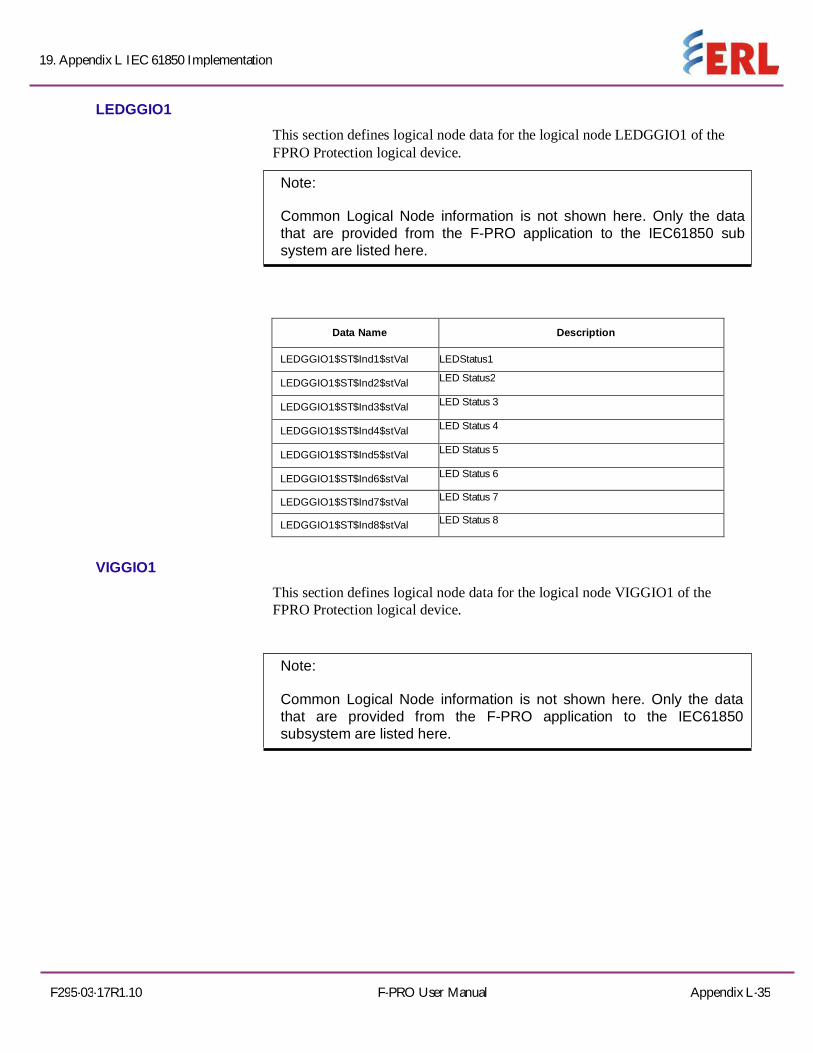
19. Appendix L IEC 61850 Implementation
F295-03-17R1.10 F-PRO User Manual Appendix L-35
LEDGGIO1
This section defines logical node data for the logical node LEDGGIO1 of the FPRO Protection logical device.
Note:
Common Logical Node information is not shown here. Only the data that are provided from the F-PRO application to the IEC61850 sub system are listed here.
Data Name
Description
LEDGGIO1$ST$Ind1$stVal LEDStatus1
LEDGGIO1$ST$Ind2$stVal LED Status2
LEDGGIO1$ST$Ind3$stVal LED Status 3
LEDGGIO1$ST$Ind4$stVal LED Status 4
LEDGGIO1$ST$Ind5$stVal LED Status 5
LEDGGIO1$ST$Ind6$stVal LED Status 6
LEDGGIO1$ST$Ind7$stVal LED Status 7
LEDGGIO1$ST$Ind8$stVal LED Status 8
VIGGIO1
This section defines logical node data for the logical node VIGGIO1 of the FPRO Protection logical device.
Note:
Common Logical Node information is not shown here. Only the data that are provided from the F-PRO application to the IEC61850 subsystem are listed here.

19. Appendix L IEC 61850 Implementation
F295-03-17R1.10 F-PRO User Manual Appendix L-36
Data Name
Description
VIGGIO1$ST$Ind1$stVal Virtual Input1
VIGGIO1$ST$Ind2$stVal Virtual Input2
VIGGIO1$ST$Ind3$stVal Virtual Input3
VIGGIO1$ST$Ind4$stVal Virtual Input4
VIGGIO1$ST$Ind5$stVal Virtual Input5
VIGGIO1$ST$Ind6$stVal Virtual Input6
VIGGIO1$ST$Ind7$stVal Virtual Input7
VIGGIO1$ST$Ind8$stVal Virtual Input8
VIGGIO1$ST$Ind9$stVal Virtual Input9
VIGGIO1$ST$Ind10$stVal Virtual Input10
VIGGIO1$ST$Ind11$stVal Virtual Input11
VIGGIO1$ST$Ind12$stVal Virtual Input12
VIGGIO1$ST$Ind13$stVal Virtual Input13
VIGGIO1$ST$Ind14$stVal Virtual Input14
VIGGIO1$ST$Ind15$stVal Virtual Input15
VIGGIO1$ST$Ind16$stVal Virtual Input16
VIGGIO1$ST$Ind17$stVal Virtual Input17
VIGGIO1$ST$Ind18$stVal Virtual Input18
VIGGIO1$ST$Ind19$stVal Virtual Input19
VIGGIO1$ST$Ind20$stVal Virtual Input20
VIGGIO1$ST$Ind21$stVal Virtual Input21
VIGGIO1$ST$Ind22$stVal Virtual Input22
VIGGIO1$ST$Ind23$stVal Virtual Input23
VIGGIO1$ST$Ind24$stVal Virtual Input24
VIGGIO1$ST$Ind25$stVal Virtual Input25
VIGGIO1$ST$Ind26$stVal Virtual Input26
VIGGIO1$ST$Ind27$stVal Virtual Input27
VIGGIO1$ST$Ind28$stVal Virtual Input28
VIGGIO1$ST$Ind29$stVal Virtual Input29
VIGGIO1$ST$Ind30$stVal Virtual Input30

19. Appendix L IEC 61850 Implementation
F295-03-17R1.10 F-PRO User Manual Appendix L-36
VIGGIO2 This section defines logical node data for the logical nodeVIGGIO2 of the FPRO Protection logical device.
Note:
Common Logical Node information is not shown here. Only the data that are provided from the F-PRO application to the IEC61850 subsystem are listed here.
Data Name
Description
VIGGIO2$ST$Ind1$stVal Subscribed GOOSE Virtual Input1
VIGGIO2$ST$Ind2$stVal Subscribed GOOSE Virtual Input2 VIGGIO2$ST$Ind3$stVal Subscribed GOOSE Virtual Input3 VIGGIO2$ST$Ind4$stVal Subscribed GOOSE Virtual Input4 VIGGIO2$ST$Ind5$stVal Subscribed GOOSE Virtual Input5 VIGGIO2$ST$Ind6$stVal Subscribed GOOSE Virtual Input6 VIGGIO2$ST$Ind7$stVal Subscribed GOOSE Virtual Input7 VIGGIO2$ST$Ind8$stVal Subscribed GOOSE Virtual Input8 VIGGIO2$ST$Ind9$stVal Subscribed GOOSE Virtual Input9 VIGGIO2$ST$Ind10$stVal Subscribed GOOSE Virtual Input10 VIGGIO2$ST$Ind11$stVal Subscribed GOOSE Virtual Input11 VIGGIO2$ST$Ind12$stVal Subscribed GOOSE Virtual Input12 VIGGIO2$ST$Ind13$stVal Subscribed GOOSE Virtual Input13 VIGGIO2$ST$Ind14$stVal Subscribed GOOSE Virtual Input14 VIGGIO2$ST$Ind15$stVal Subscribed GOOSE Virtual Input15 VIGGIO2$ST$Ind16$stVal Subscribed GOOSE Virtual Input16 VIGGIO2$ST$Ind17$stVal Subscribed GOOSE Virtual Input17 VIGGIO2$ST$Ind18$stVal Subscribed GOOSE Virtual Input18 VIGGIO2$ST$Ind19$stVal Subscribed GOOSE Virtual Input19 VIGGIO2$ST$Ind20$stVal Subscribed GOOSE Virtual Input20 VIGGIO2$ST$Ind21stVal Subscribed GOOSE Virtual Input21 VIGGIO2$ST$Ind22$stVal Subscribed GOOSE Virtual Input22 VIGGIO2$ST$Ind23$stVal Subscribed GOOSE Virtual Input23 VIGGIO2$ST$Ind24$stVal Subscribed GOOSE Virtual Input24 VIGGIO2$ST$Ind25$stVal Subscribed GOOSE Virtual Input25 VIGGIO2$ST$Ind26$stVal Subscribed GOOSE Virtual Input26 VIGGIO2$ST$Ind27$stVal Subscribed GOOSE Virtual Input27 VIGGIO2$ST$Ind28$stVal
Subscribed GOOSE Virtual Input28 VIGGIO2$ST$Ind29$stVal
Subscribed GOOSE Virtual Input29 VIGGIO2$ST$Ind30$stVal
Subscribed GOOSE Virtual Input30

19. Appendix L IEC 61850 Implementation
Appendix L-38 F-PRO User Manual F295-03-17R1.10
VIGGIO3 This section defines logical node data for the logical node VIGGIO3 of the
FPRO Protection logical device.
Note: Common Logical Node information is not shown here. Only the data that are provided from the F-PRO application to the IEC61850 subsystem are listed here.
Data Name
Description
VIGGIO3$ST$Ind1$stVal Virtual Output Control1
VIGGIO3$ST$Ind2$stVal Virtual Output Control 2
VIGGIO3$ST$Ind3$stVal Virtual Output Control 3
VIGGIO3$ST$Ind4$stVal Virtual Output Control 4
VIGGIO3$ST$Ind5$stVal Virtual Output Control 5
VIGGIO3$ST$Ind6$stVal Virtual Output Control 6
VIGGIO3$ST$Ind7$stVal Virtual Output Control 7
VIGGIO3$ST$Ind8$stVal Virtual Output Control 8
VIGGIO3$ST$Ind9$stVal Virtual Output Control 9
VIGGIO3$ST$Ind10$stVal Virtual Output Control 10
VIGGIO3$ST$Ind11$stVal Virtual Output Control 11
VIGGIO3$ST$Ind12$stVal Virtual Output Control 12
VIGGIO3$ST$Ind13$stVal Virtual Output Control 13
VIGGIO3$ST$Ind14$stVal Virtual Output Control 14
VIGGIO3$ST$Ind15$stVal Virtual Output Control 15
VIGGIO3$ST$Ind16$stVal Virtual Output Control 16
VIGGIO3$ST$Ind17$stVal Virtual Output Control 17
VIGGIO3$ST$Ind18$stVal Virtual Output Control 18
VIGGIO3$ST$Ind19$stVal Virtual Output Control 19
VIGGIO3$ST$Ind20$stVal Virtual Output Control 20
VIGGIO3$ST$Ind21$stVal Virtual Output Control 21
VIGGIO3$ST$Ind22$stVal Virtual Output Control 22
VIGGIO3$ST$Ind23$stVal Virtual Output Control 23
VIGGIO3$ST$Ind24$stVal Virtual Output Control 24 VIGGIO3$ST$Ind25$stVal Virtual Output Control 25
VIGGIO3$ST$Ind26$stVal Virtual Output Control 26
VIGGIO3$ST$Ind27$stVal Virtual Output Control 27
VIGGIO3$ST$Ind28$stVal Virtual Output Control 28
VIGGIO3$ST$Ind29$stVal Virtual Output Control 29
VIGGIO3$ST$Ind30$stVal Virtual Output Control 30

19. Appendix L IEC 61850 Implementation
F295-03-17R1.10 F-PRO User Manual Appendix L-39
Fault Data Logical Nodes This section defines the logical nodes available for fault data under the FPRO Fault Data logical device. All the protection functions are grouped under 3no: of Logical Nodes detailed as below:
Logical Node Data Objects
Functions Defined
FLTMMXU1$MX$PhV Fault Voltages(VA, VB,VC,VN,VG)
FLTMSQI1$MX$SeqV Fault Voltage(V2)
FLTMMXU1$MX$Hz Fault Frequency
FLTMMXU1$MX$A$neut Fault Current(I2)
FLTDATA1
This section defines the logical node data for the logical node FLTDATA1 of the FPRO Fault Data logical device.
Note:
Common Logical Node information is not shown here. Only the data that are provided from the F-PRO application to the IEC 61850
sub-system are listed here
DataName
Description
FLTMMXU1$MX$PhV$phsA$cVal$mag$f VA- Magnitude
FLTMMXU1$MX$PhV$phsA$cVal$ang$f VA- Angle
FLTMMXU1$MX$PhV$phsB$cVal$mag$f VB -Magnitude
FLTMMXU1$MX$PhV$phsB$cVal$ang$f VB- Angle
FLTMMXU1$MX$PhV$phsC$cVal$mag$f VC - Magnitude
FLTMMXU1$MX$PhV$phsC$cVal$ang$f VC-Angle
FLTMMXU1$MX$PhV$neut$cVal$mag$f VN– Magnitude
FLTMMXU1$MX$PhV$neut$cVal$ang$f VN– Angle
FLTMMXU1$MX$PhV$res$cVal$mag$f VG– Magnitude
FLTMMXU1$MX$PhV$res$cVal$ang$f VG– Angle
FLTMSQI1$MX$SeqV$c2$cVal$mag$f V2 – Neg.Seq. Magnitude(46/50,46/51)
FLTMMXU1$MX$Hz$mag$f Frequency
FLTMMXU1$MX$A$neut$cVal$mag$f IN– Magnitude
FLTMMXU1$MX$A$neut$cVal$ang$f IN– Angle