Embed Size (px)
Citation preview
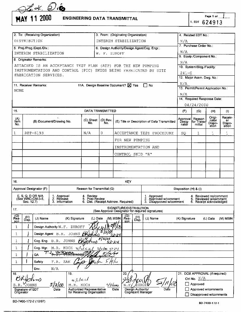
2. To: (Receiving Organization) 3. From: (Originating Organization) 4. Related EDT No.:
N/A I O . System/Bldg./Facility
241-G
ATTACHED IS AN ACCEPTANCE TEST PLAN (ATP) FOR THE NEW PUMPING INSTRUMENTATION AND CONTROL (PIC) SKIDS BEING FABRICATED BY SITE FABRICATION SERVICES.
12. Major Assm. Dwg. No.:
DISTRIBUTION
5. Proj.lProg.lDept.1Div.:
INTERIM STABILIZATION
N/A 13. PermiVPermit Application No.:
11. Receiver Remarks: 11A. Design Baseline Document? Yes 0 No
NONE
INTERIM STABILIZATION N/A ~ 7. Purchase Order No.: 6. Design AuthoritylDesign AgenffCog. Engr.:
W. F. ZUROFF N/A 9. Equip.1Component No.:
N/A 14. Required Response Date:
15. DATA TRANSMITTED
.. (8) DocumenVDrawing No. ( ')$Pt ( D h 2 y (E) Title or Description of Data Transmitted
(A) Item No.
0 4 / 2 4 / 2 0 0 0
(F) (G) (H) (1)
A proVal R~~~~~ Origi- Re-iv- gesig- for Trans- &":,. Di$o- 'ator mitt'' stion sition
~
Approval Designator (F) Reason for Transmittal (G) Disposition (H) & (I)
I I Env. N/A
E, S, 0, D OR NIA (See WHC-CM-3-5.
Sec. 12.7)
Signature of EDT Date Originator
1. Ap roval 4. Review 1. Approved 4. Reviewed nolcomment 2. ReLase 5. Post-Review 2. Approved wlcomment 5. Reviewed wlwmment 3. information 6. Dist. (Receipt Acknow. Required) 3. Disapproved wlwrnment 6. Receipt acknowledged
I I 19 1 2 0 / 9 -/ I 21 DOE APPROVAL (if required)
Ctrl NO. N/A
0 Approved wlwmments
0 Disapproved wlwmments
]Ll?l t L i
M.R. KOCH WAI" Authorized Re resentative Date for Receiving Brganization
ED-7400-172-2 (10197) 80-7400-1 72-1
RPP-6193, Rev. 0
ACCEPTANCE TEST PROCEDURE FOR NEW PUMPING INSTRUMENTATION AND CONTROL SKID "R"
M. R. KOCH CHZMHILL HANFORD GROUP, INC Richland, WA 99352 US. Department of Energy Contract DE-AC06-99RL14047
EDTIECN: 6 2 4 9 1 3 u c : Cost Center: 7 4 D 0 0 Charge Code: 103361 B&R Code: EW3 1 2 0 0 7 1 Total Pages: 56
Keywords: PICS, SALT WELL, SKID, INTERIM STABILIZATION, ACCEPTANCE TEST
Abstract: This Acceptance Test Procedure (ATP) provides for the inspection and testing of the new Pumping Insstrumentation and Control (PIC) skid designed as "R". The ATP will be performed after the construction of the PIC skid in the fabrication shop.
TRADEMARK DISCLAIMER. Reference herein to any specific commercial product. process, or Service by trade name, trademark, manufacturer, or otherwise, does not necessarily constitute or imply its endorsement, recommendation. or favoring by the United States Government or any agency thereof or its contractors or subcontractors.
Printed in the United States of America. To obtain copies of this document, contact: Dowment Control Services. P.O. Box 950, Mailstop H6-08. Richland WA 99352, Phone (509) 372-2420; Fax (509) 3764989.
Approved For Public Release
A-6002-767 (10/99)
RPP-6193 REVISION 0
TABLE OF CONTENTS
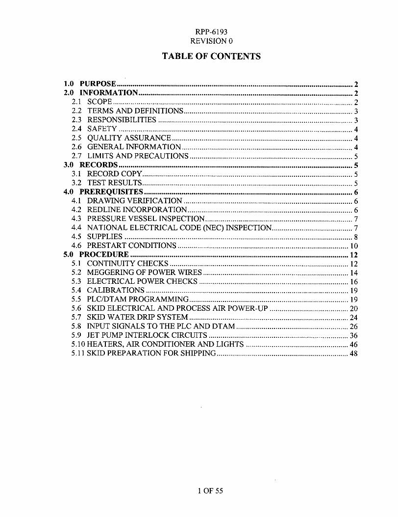
1.0 PURPOSE ........................................................................................................................ 2 2.0 INFORMATION ............................................................................................................. 2
2.1 SCOPE .......................................................................................................................... 2 2.2 TERMS AND DEFINITIONS ..................... ........................................................... 3 2.3 RESPONSIBILITIES ................................................................................................... 3 2.4 SAFETY ....................................................................................................................... 4 2.5 QUALITY ASSURANCE ............................................................................................ 4 2.6 GENERAL INFORMATION ....................................................................................... 4 2.7 LIMITS AND PRECAUTIONS ................................................................................... 5
3.0 RECORDS ....................................................................................................................... 5 3.1 RECORD COPY ........................................................................................................... 5 3.2 TEST RESULTS ........................................................................................................... 5
4.0 PREREQUISITES .......................................................................................................... 6 4.1 DRAWING VERIFICATION ...................................................................................... 6 4.2 REDLINE INCORPORATION .................................................................................... 6 4.3 PRESSURE VESSEL INSPECTION ........................................................................... 7 4.4 NATIONAL ELECTRICAL CODE (NEC) INSPECTION ......................................... 7 4.5 SUPPLIES .................................................................................................................... 8 4.6 PRESTART CONDITIONS ....................................................................................... 10
5.0 PROCEDURE ............................................................................................................... 12 5.1 CONTINUITY CHECKS ........................................................................................... 12 5.2 MEGGERING OF POWER WIRES . ..................................................................... 14 5.3 ELECTRICAL POWER CHECKS ............................................................................ 16 5.4 CALIBRATIONS ....................................................................................................... 19 5.5 PLCDTAM PROGRAMMING ................................................................................. 19
5.7 SKID WATER DRIP SYSTEM ................................................................................. 24 5.8 INPUT SIGNALS TO THE PLC AND DTAM ......................................................... 26 5.9 JET PUMP INTERLOCK CIRCUITS ....................................................................... 36 5.10 HEATERS, AIR CONDITIONER AND LIGHTS .................................................... 46 5.1 1 SKID PREPARATION FOR SHIPPING ................................................................... 48
5.6 SKID ELECTRICAL AND PROCESS AIR POWER-UP ........................................ 20
1 OF 55
RPP-6193 REVISION 0
ACCEPTANCE TEST PROCEDURE FOR NEW PUMPING INSTRUMENTATION AND CONTROL SKID “R”
1.0 PURPOSE
This Acceptance Test Procedure (ATP) verifies proper construction per the design drawings and tests for proper functioning of the Pumping Instrumentation and Control (PIC) skid “ R . The scope section lists the systems and functions to be checked. This ATP will be performed at the Site Fabrication Services (SFS) shop upon completion of the construction of the PIC skid.
2.0 INFORMATION
2.1 SCOPE
This Acceptance Test Procedure verifies and/or tests the following items or systems:
2.1.1 Drawing verification (Prerequisites) 2.1.2 Red-line incorporation 2.1.3 Code Inspections (Prerequisites) 2.1.4 Instrument calibrations 2.1.5 2.1.6
2.1.7 Air system 2.1.8 Water system 2.1.9 PLC inputs and outputs 2.1.10 Alarms and interlocks 2.1.1 1 Heaters, air conditioner and lights
Continuity, megger and voltage checks Programmable Logic Controller (PLC) and Data Table Access Module (DTAM) programming
2 OF 55
-
RPP-6193 REVISION 0
2.2 TERMS AND DEFINITIONS
2.2.1 DOV - Diaphragm Operated Valve 2.2.2 GPM - Gallons Per Minute 2.2.3 IA - Instrument Air 2.2.4 LDE - Leak Detector Element 2.2.5 PRV - Pressure Relief Valve 2.2.6 SGT - Specific Gravity Transmitter 2.2.7 WFT - Weight Factor Transmitter 2.2.8 LT - Level Transmitter 2.2.9 WFIE - Weight Factor Instrument Enclosure 2.2.10 PLC - Programmable Logic Controller 2.2.1 1 DTAM - Data Table Access Module 2.2.12 PSPT - Pump Suction Pressure Transducer 2.2.13 PDPT - Pump Discharge Pressure Transducer 2.2.14 PXPT - Pump Transfer Pressure Transducer 2.2.15 JFPT - Jumper Flush Pressure Transducer 2.2.16 RFPT - Recirculation Flush Pressure Transducer 2.2.17 PIC - Person In Charge
2.3 RESPONSIBILITIES
2.3.1 CHG Quality Assurance is responsible for: 2.3.1.1
2.3.1.2 2.3.1.3 Test Engineer (or representative) and/or PIC are responsible for: 2.3.2.1 2.3.2.2 2.3.2.3 Conducting pre-job system walk-down. 2.3.2.4 2.3.2.5 2.3.2.6 2.3.2.7 2.3.2.8
Witnessing and signing steps as identified in the Acceptance Test Procedure. Verifying that the ATP sections were performed correctly. Approving Exception resolution and exception closure.
Identifying the equipment required for the ATP. Recording equipment status and data per this ATP.
Recording data and other notes during the ATP performance. Providing technical support during the ATP. Providing PLCDTAM programming support during the ATP. Acting as Test Director during the ATP. Approving Exception resolution and exception closure.
2.3.2
3 OF 55
RPP-6193 REVISION 0
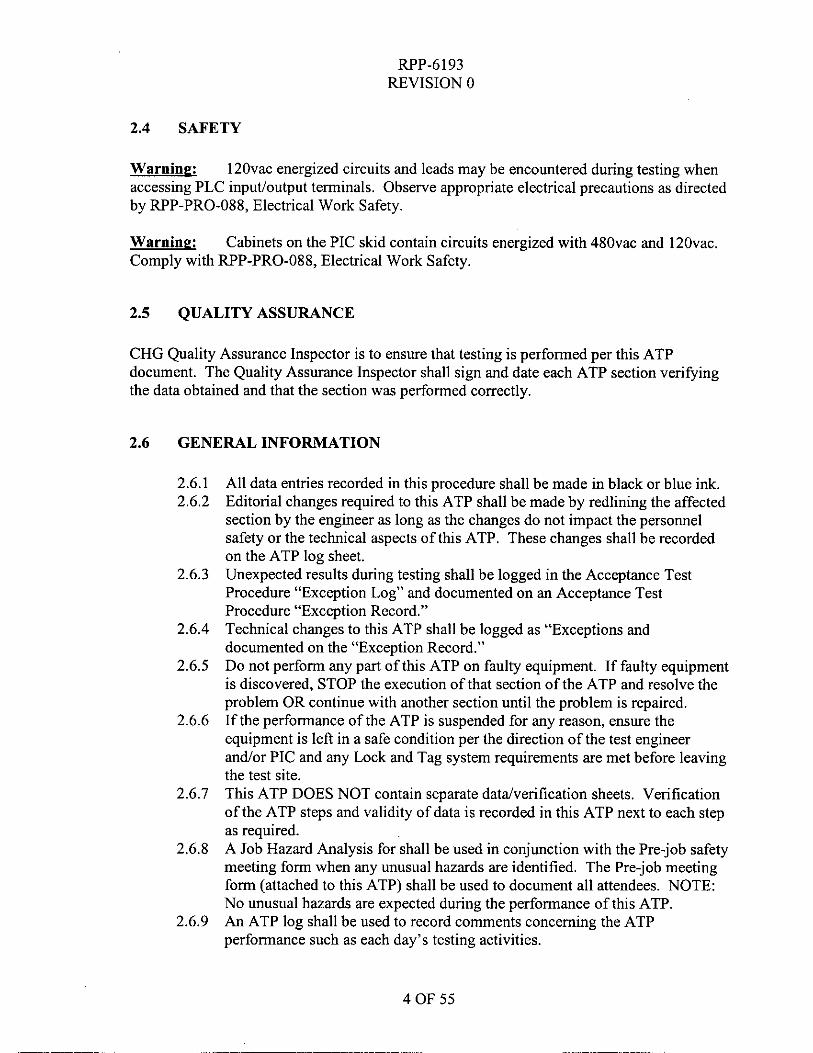
2.4 SAFETY
Warning: accessing PLC input/output terminals. Observe appropriate electrical precautions as directed by RPP-PRO-088, Electrical Work Safety.
Warning: Comply with RPP-PRO-088, Electrical Work Safety.
12Ovac energized circuits and leads may be encountered during testing when
Cabinets on the PIC skid contain circuits energized with 480vac and 120vac.
2.5 QUALITY ASSURANCE
CHG Quality Assurance Inspector is to ensure that testing is performed per this ATP document. The Quality Assurance Inspector shall sign and date each ATP section verifying the data obtained and that the section was performed correctly.
2.6 GENERAL INFORMATION
2.6.1 2.6.2
2.6.3
2.6.4
2.6.5
2.6.6
2.6.7
2.6.8
2.6.9
All data entries recorded in this procedure shall be made in black or blue ink. Editorial changes required to this ATP shall be made by redlining the affected section by the engineer as long as the changes do not impact the personnel safety or the technical aspects of this ATP. These changes shall be recorded on the ATP log sheet. Unexpected results during testing shall be logged in the Acceptance Test Procedure “Exception Log” and documented on an Acceptance Test Procedure “Exception Record.” Technical changes to this ATP shall be logged as “Exceptions and documented on the “Exception Record.” Do not perform any part of this ATP on faulty equipment. If faulty equipment is discovered, STOP the execution of that section of the ATP and resolve the problem OR continue with another section until the problem is repaired. If the performance of the ATP is suspended for any reason, ensure the equipment is left in a safe condition per the direction of the test engineer and/or PIC and any Lock and Tag system requirements are met before leaving the test site. This ATP DOES NOT contain separate datdverification sheets. Verification of the ATP steps and validity of data is recorded in this ATP next to each step as required. A Job Hazard Analysis for shall be used in conjunction with the Pre-job safety meeting form when any unusual hazards are identified. The Pre-job meeting form (attached to this ATP) shall be used to document all attendees. NOTE: No unusual hazards are expected during the performance of this ATP. An ATP log shall be used to record comments concerning the ATP performance such as each day’s testing activities.
4 OF 55
RPP-6193 REVISION 0
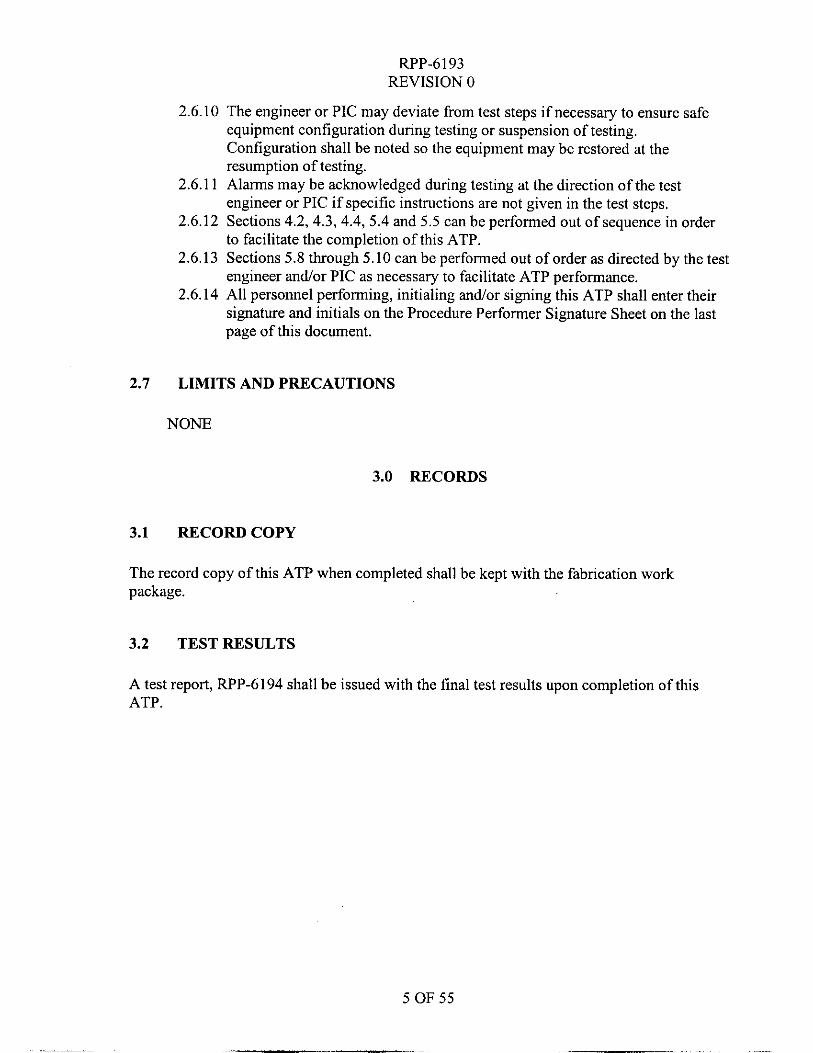
2.6.10 The engineer or PIC may deviate from test steps if necessary to ensure safe equipment configuration during testing or suspension of testing. Configuration shall be noted so the equipment may be restored at the resumption of testing.
2.6.1 1 Alarms may be acknowledged during testing at the direction of the test engineer or PIC if specific instructions are not given in the test steps.
2.6.12 Sections 4.2,4.3, 4.4, 5.4 and 5.5 can be performed out of sequence in order to facilitate the completion of this ATP.
2.6.13 Sections 5.8 through 5.10 can be performed out of order as directed by the test engineer and/or PIC as necessary to facilitate ATP performance.
2.6.14 All personnel performing, initialing and/or signing this ATP shall enter their signature and initials on the Procedure Performer Signature Sheet on the last page of this document.
2.7 LIMITS AND PRECAUTIONS
NONE
3.0 RECORDS
3.1 RECORDCOPY
The record copy of this ATP when completed shall be kept with the fabrication work package.
3.2 TEST RESULTS
A test report, RPP-6194 shall be issued with the final test results upon completion of this ATP.
5 OF 55
RPP-6193 REVISION 0
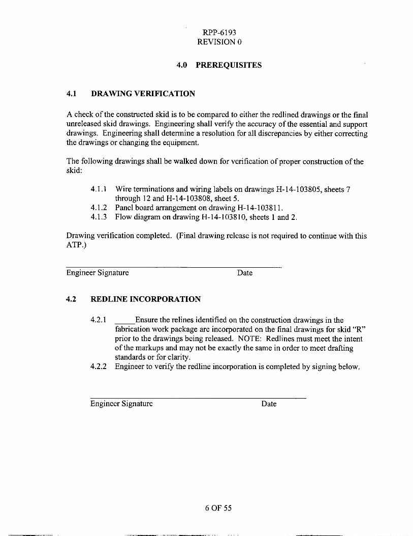
4.0 PREREQUISITES
4.1 DRAWING VERIFICATION
A check of the constructed skid is to be compared to either the redlined drawings or the final unreleased skid drawings. Engineering shall verify the accuracy of the essential and support drawings. Engineering shall determine a resolution for all discrepancies by either correcting the drawings or changing the equipment.
The following drawings shall be walked down for verification of proper construction of the skid:
4.1.1 Wire terminations and wiring labels on drawings H-14-103805, sheets 7 through 12 and H-14-103808, sheet 5.
4.1.2 Panel board arrangement on drawing H-14-103811. 4.1.3 Flow diagram on drawing H-14-103810, sheets 1 and 2.
Drawing verification completed. (Final drawing release is not required to continue with this ATP.)
Engineer Signature Date
4.2 REDLINE INCORPORATION
4.2.1 ~ Ensure the relines identified on the construction drawings in the fabrication work package are incorporated on the final drawings for skid “ R prior to the drawings being released. NOTE: Redlines must meet the intent of the markups and may not be exactly the same in order to meet drafting standards or for clarity. Engineer to verify the redline incorporation is completed by signing below. 4.2.2
Engineer Signature Date
6 OF 55
.-
RPP-6193 REVISION 0
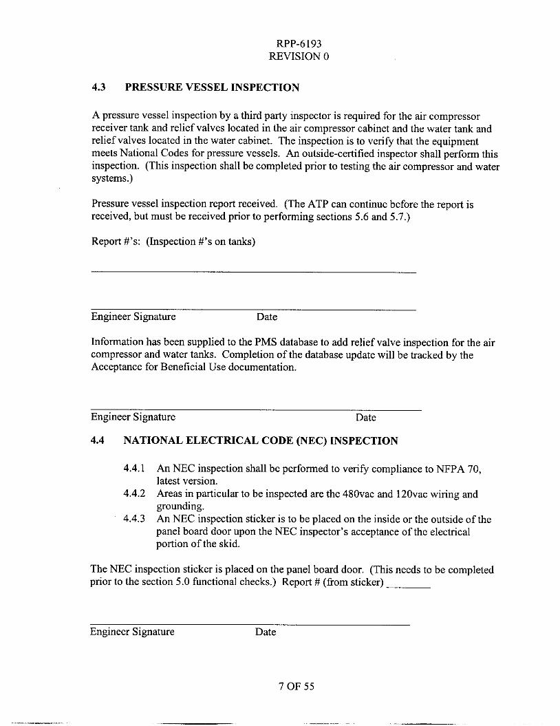
4.3 PRESSURE VESSEL INSPECTION
A pressure vessel inspection by a third party inspector is required for the air compressor receiver tank and relief valves located in the air compressor cabinet and the water tank and relief valves located in the water cabinet. The inspection is to verify that the equipment meets National Codes for pressure vessels. An outside-certified inspector shall perform this inspection. (This inspection shall be completed prior to testing the air compressor and water systems.)
Pressure vessel inspection report received. (The ATP can continue before the report is received, but must be received prior to performing sections 5.6 and 5.7.)
Report #'s: (Inspection #'s on tanks)
Engineer Signature Date
Information has been supplied to the PMS database to add relief valve inspection for the air compressor and water tanks. Completion of the database update will be tracked by the Acceptance for Beneficial Use documentation.
Engineer Signature Date
4.4 NATIONAL ELECTRICAL CODE (NEC) INSPECTION
@PA 7 4.4.1 An NEC inspection shall be performed to verify compliance to latest version.
4.4.2
4.4.3
Areas in particular to be inspected are the 480vac and 120vac wiring and grounding. An NEC inspection sticker is to be placed on the inside or the outside of the panel board door upon the NEC inspector's acceptance of the electrical portion of the skid.
The NEC inspection sticker is placed on the panel board door. (This needs to be completed prior to the section 5.0 functional checks.) Report # (from sticker)
Engineer Signature Date
7 OF 55
RPP-6193 REVISION 0
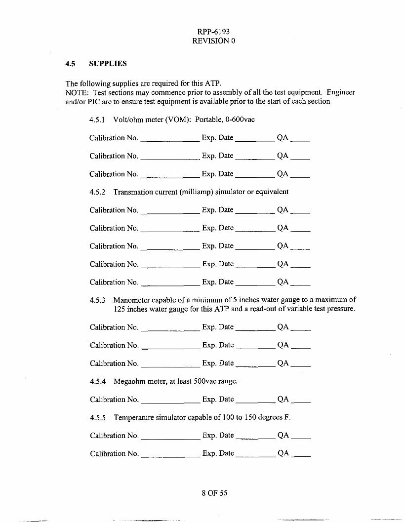
4.5 SUPPLIES
The following supplies are required for this ATP. NOTE: Test sections may commence prior to assembly of all the test equipment. Engineer and/or PIC are to ensure test equipment is available prior to the start of each section.
4.5.1 Volt/ohm meter (VOM): Portable, 0-600vac
Calibration No. Exp. Date QA -
QA -
Calibration No. Exp. Date QA -
Calibration No. Exp. Date
4.5.2
Calibration No. Exp. Date
Transmation current (milliamp) simulator or equivalent
QA -
Calibration No. Exp. Date QA -
Calibration No. Exp. Date QA __
Calibration No. Exp. Date QA __
Calibration No. Exp. Date QA - 4.5.3 Manometer capable of a minimum of 5 inches water gauge to a maximum of
125 inches water gauge for this ATP and a read-out of variable test pressure.
Calibration No. Exp. Date QA -
Calibration No. Exp. Date QA - Calibration No. Exp. Date QA -
4.5.4
Calibration No. Exp. Date
4.5.5
Megaobm meter, at least 5OOvac range.
QA -
Temperature simulator capable of 100 to 150 degrees F.
Calibration No. Exp. Date QA -
Calibration No. Exp. Date QA -
8 OF 55
WP-6193 REVISION 0
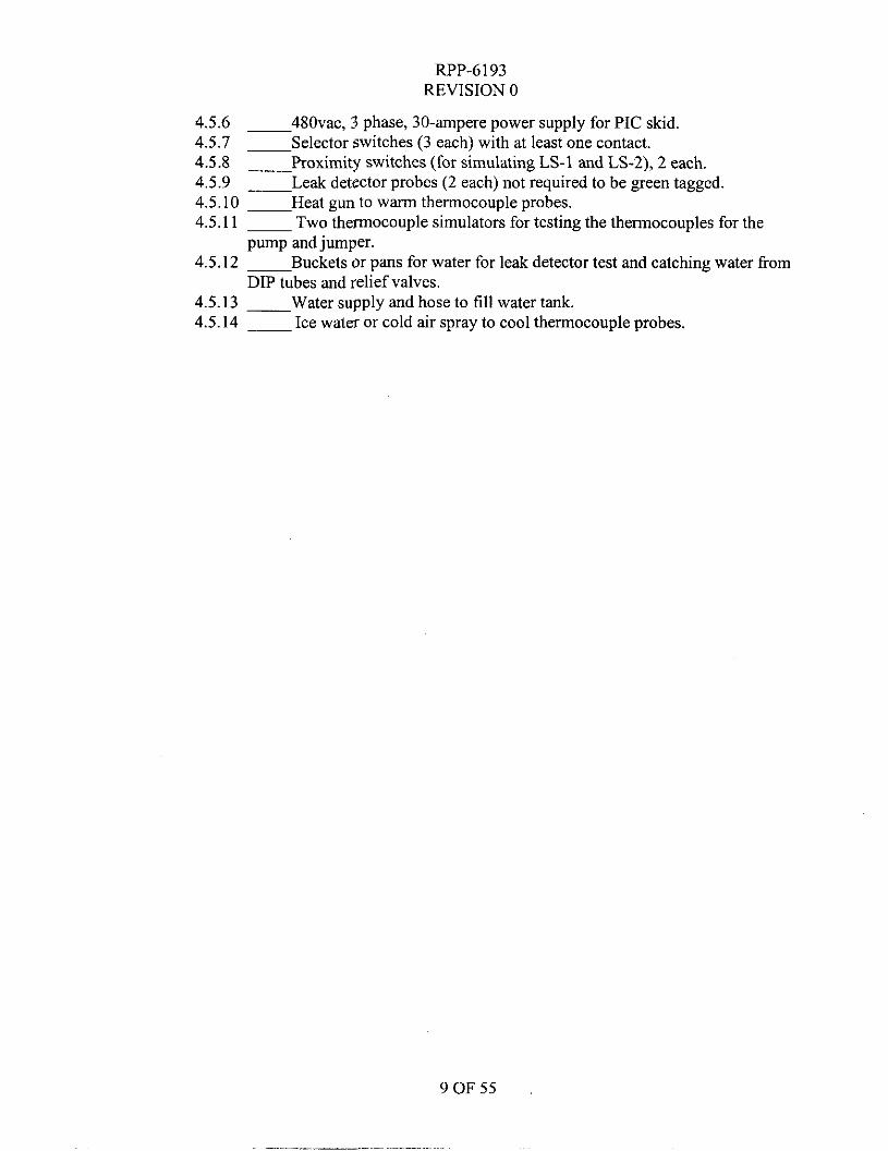
4.5.6 4.5.7 ~ Selector switches (3 each) with at least one contact. 4.5.8 __ Proximity switches (for simulating LS-1 and LS-2), 2 each. 4.5.9 __ Leak detector probes (2 each) not required to be green tagged. 4.5.10 ~ Heat gun to warm thermocouple probes. 4.5.11 ~ Two thermocouple simulators for testing the thermocouples for the
4.5.12 ~ Buckets or pans for water for leak detector test and catching water fiom
4.5.13 __ Water supply and hose to fill water tank. 4.5.14 ~ Ice water or cold air spray to cool thermocouple probes.
480vac, 3 phase, 30-ampere power supply for PIC skid.
pump and jumper.
DIP tubes and relief valves.
9 OF 5 5
RPP-6193 REVISION 0
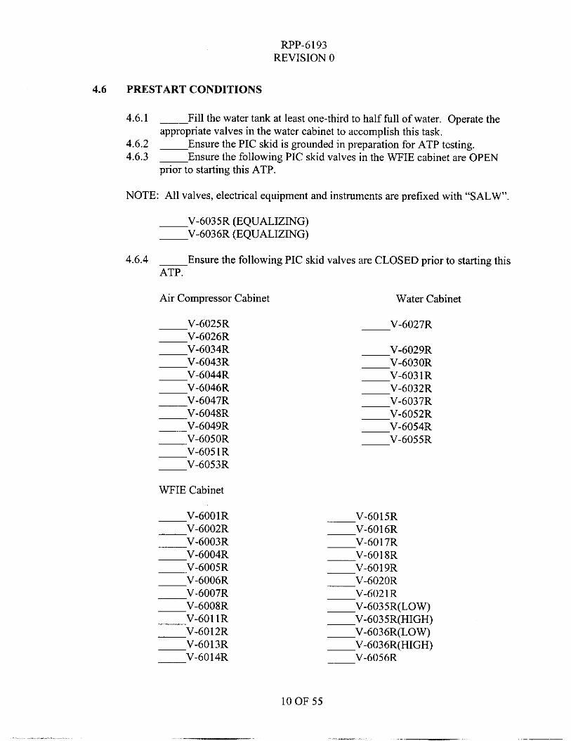
4.6 PRESTART CONDITIONS
4.6.1
4.6.2 4.6.3
Fill the water tank at least one-third to half full of water. Operate the
Ensure the PIC skid is grounded in preparation for ATP testing. Ensure the following PIC skid valves in the WFIE cabinet are OPEN
appropriate valves in the water cabinet to accomplish this task.
prior to starting this ATP.
NOTE: All valves, electrical equipment and instruments are prefixed with “SALW’.
-V-6035R (EQUALIZING) -V-6036R (EQUALIZING)
4.6.4 Ensure the following PIC skid valves are CLOSED prior to starting this ATP.
Air Compressor Cabinet Water Cabinet
-V-6025R V - 6 0 2 6 R -V-6034R -V-6043R -V-6044R -V-6046R -V-6047R -V-6048R -V-6049R -V-6050R -V-605 1R -V-6053R
WFIE Cabinet
-V-6001R -V-6002R -V-6003R
V-6004R -V-6005R -V-6006R -V-6007R
V-6008R
-V-6012R V-6013R
-V-6011R
-V-6014R
V-602 1 R -V-6035R(LOW) -V-6035R(HIGH) -V-6036R(LOW) -V-6036R(HIGH)
V-6056R
10 OF 55
RPP-6193 REVISION 0
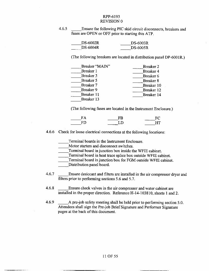
4.6.5 - Ensure the following PIC skid circuit disconnects, breakers and fuses are OPEN or OFF prior to starting this ATP.
-DS-6002R -DS-6003R -DS-6004R -DS-6005R
(The following breakers are located in distribution panel DP-6001R.)
-Breaker “MAIN” -Breaker 2 -Breaker 1 -Breaker 4 -Breaker 3 -Breaker 6 B r e a k e r 5 -Breaker 8 -Breaker 7 B r e a k e r 10 -Breaker 9 -Breaker 12 -Breaker 11 -Breaker 14 -Breaker 13
(The following fuses are located in the Instrument Enclosure.)
FA F B -FC -FD -LD H T
4.6.6 Check for loose electrical connections at the following locations:
-Terminal boards in the Instrument Enclosure. -Motor starters and disconnect switches. -Terminal board in junction box inside the WFIE cabinet. -Terminal board in heat trace splice box outside WFIE cabinet. -Terminal board injunction box for FGM outside WFIE cabinet. -Distribution panel board.
4.6.7 - Ensure desiccant and filters are installed in the air compressor dryer and filters prior to performing sections 5.6 and 5.7.
4.6.8 -Ensure check valves in the air compressor and water cabinet are installed in the proper direction. Reference H-14-103810, sheets 1 and 2.
4.6.9 - A pre-job safety meeting shall be held prior to performing section 5.0. Attendees shall sign the Pre-job Brief Signature and Performer Signature pages at the back of this document.
11 OF55
RPP-6193 REVISION 0
5.0 PROCEDURE
5.1 CONTINUITY CHECKS
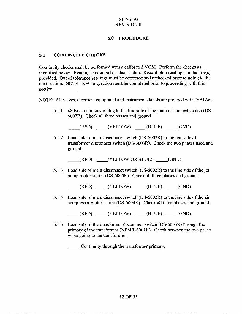
Continuity checks shall be performed with a calibrated VOM. Perform the checks as identified below. Readings are to be less than 1 ohm. Record ohm readings on the line(s) provided. Out of tolerance readings must be corrected and rechecked prior to going to the next section. NOTE: NEC inspection must be completed prior to proceeding with this section.
NOTE: All valves, electrical equipment and instruments labels are prefixed with “SALW’.
480vac main power plug to the line side of the main disconnect switch (DS- 6002R). Check all three phases and ground.
5.1.1
-(RED) - (YELLOW) ___ (BLUE) ~ (GND)
5.1.2 Load side of main disconnect switch (DS-6002R) to the line side of transformer disconnect switch (DS-6003R). Check the two phases used and ground.
5.1.3 Load side of main disconnect switch (DS-6002R) to the line side of the jet pump motor starter (DS-6005R). Check all three phases and ground.
-(RED) - (YELLOW) - (BLUE) (GND)
5.1.4 Load side of main disconnect switch (DS-6002R) to the line side of the air compressor motor starter (DS-6004R). Check all three phases and ground.
-(RED) - (YELLOW) - (BLUE) - (GND)
5.1.5 Load side of the transformer disconnect switch (DS-6003R) through the primary of the transformer (XFMR-6001R). Check between the two phase wires going to the transformer.
Continuity through the transformer primary.
12 OF 55
RPP-6193 REVISION 0
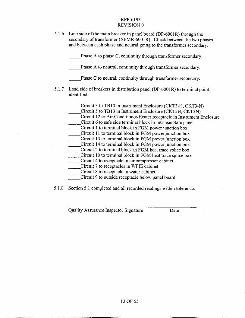
5.1.6 Line side of the main breaker in panel board (DP-6001R) through the secondary of transformer (XFMR-6001R). Check between the two phases and between each phase and neutral going to the transformer secondary.
-Phase A to phase C, continuity through transformer secondary.
-Phase A to neutral, continuity through transformer secondary.
-Phase C to neutral, continuity through transformer secondary.
Load side of breakers in distribution panel (DP-6001R) to terminal point identified.
-Circuit 3 to TBlO in Instrument Enclosure (CKT3-H, CKT3-N) -Circuit 5 to TB13 in Instrument Enclosure (CKTSH, CKTSN) -Circuit 12 to Air Conditionerrneater receptacle in Instrument Enclosure -Circuit 6 to safe side terminal block in Intrinsic Safe panel -Circuit 1 to terminal block in FGM power junction box -Circuit 11 to terminal block in FGM power junction box -Circuit 13 to terminal block in FGM power junction box -Circuit 14 to terminal block in FGM power junction box -Circuit 2 to terminal block in FGM heat trace splice box -Circuit 10 to terminal block in FGM heat trace splice box -Circuit 4 to receptacle in air compressor cabinet -Circuit 7 to receptacles in WFIE cabinet -Circuit 8 to receptacle in water cabinet -Circuit 9 to outside receptacle below panel board
Section 5.1 completed and all recorded readings within tolerance.
5.1.7
5.1.8
Quality Assurance Inspector Signature Date
13 OF 55
RPP-6193 REVISION 0
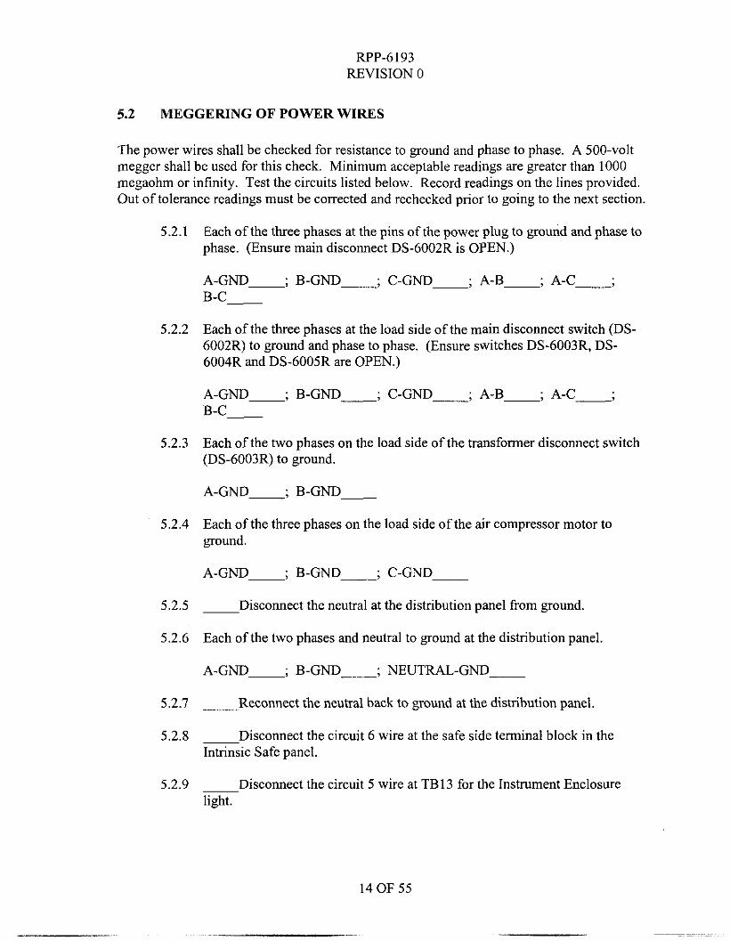
5.2 MEGGERING OF POWER WIRES
The power wires shall be checked for resistance to ground and phase to phase. A 500-volt inegger shall be used for this check. Minimum acceptable readings are greater than 1000 megaohm or infinity. Test the circuits listed below. Record readings on the lines provided. Out of tolerance readings must be corrected and rechecked prior to going to the next section.
Each of the three phases at the pins of the power plug to ground and phase to phase. (Ensure main disconnect DS-6002R is OPEN.)
5.2.1
A-GNI-, B-GND-, ' C-GND-, ' A-B-, . A-C-; B-C-
5.2.2 Each of the three phases at the load side of the main disconnect switch (DS- 6002R) to ground and phase to phase. (Ensure switches DS-6003R, DS- 6004R and DS-6005R are OPEN.)
A-GND-, ' B-GNI-; C-GND-, ' A-B-, . A-C-; B-C-
5.2.3 Each of the two phases on the load side of the transformer disconnect switch (DS-6003R) to ground.
A-GND-; B-GND-
5.2.4 Each of the three phases on the load side of the air compressor motor to ground.
A-GND-, ' B-GND-; C-GND
5.2.5 - Disconnect the neutral at the distribution panel from ground.
5.2.6 Each of the two phases and neutral to ground at the distribution panel.
A-GND-, ' B-GND-; NEUTRAL-GND-
5.2.1
5.2.8
- Reconnect the neutral back to ground at the distribution panel.
- Disconnect the circuit 6 wire at the safe side terminal block in the Intrinsic Safe panel.
- DiSCOMeCt the circuit 5 wire at TB13 for the Instrument Enclosure light.
5.2.9
14 OF 55
~. ...
RPP-6 193 REVISION 0
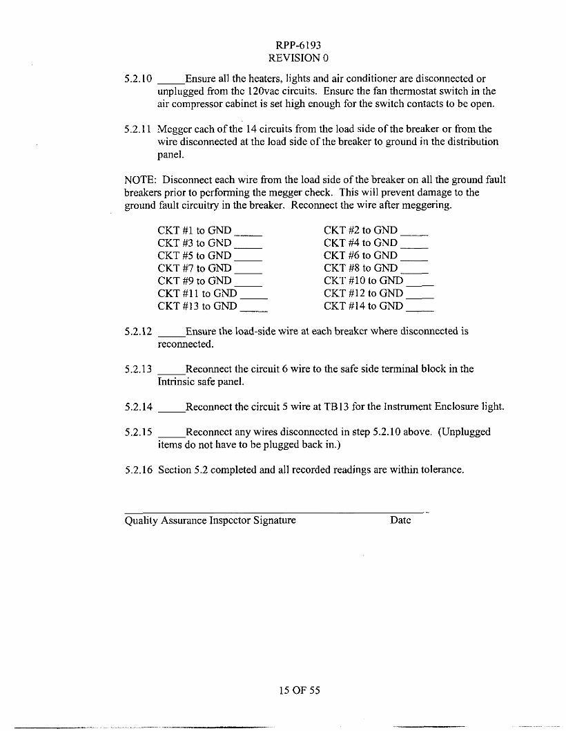
5.2.10 ~ Ensure all the heaters, lights and air conditioner are disconnected or unplugged from the 12Ovac circuits. Ensure the fan thermostat switch in the air compressor cabinet is set high enough for the switch contacts to be open.
5.2.1 1 Megger each of the 14 circuits from the load side of the breaker or from the wire disconnected at the load side of the breaker to ground in the distribution panel.
NOTE: Disconnect each wire from the load side of the breaker on all the ground fault breakers prior to performing the megger check. This will prevent damage to the ground fault circuitry in the breaker. Reconnect the wire after meggering.
CKT #1 to GND - CKT #3 to GND - CKT #5 to GND ~
CKT #7 to GND ~
CKT #9 to GND ~
CKT #I 1 to GND - CKT #13 to GND ___
CKT #2 to GND __ CKT #4 to GND __ CKT #6 to GND __ CKT #8 to GND __ CKT #10 to GND - CKT #12 to GND - CKT #I4 to GND __
5.2.12 ~ Ensure the load-side wire at each breaker where disconnected is reconnected.
5.2.13 ~ Reconnect the circuit 6 wire to the safe side terminal block in the Intrinsic safe panel.
5.2.14 ~ Reconnect the circuit 5 wire at TB13 for the Instrument Enclosure light.
5.2.15 ~ Reconnect any wires disconnected in step 5.2.10 above. (Unplugged items do not have to be plugged back in.)
5.2.16 Section 5.2 completed and all recorded readings are within tolerance.
Quality Assurance Inspector Signature Date
RF'P-6193 REVISION 0
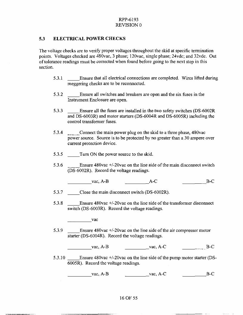
5.3 ELECTRICAL POWER CHECKS
The voltage checks are to verify proper voltages throughout the skid at specific termination points. Voltages checked are 480vac, 3 phase; 120vac, single phase; 24vdc; and 32vdc. Out of tolerance readings must be corrected when found before going to the next step in this section.
5.3.1 ~ Ensure that all electrical connections are completed. Wires lifted during meggering checks are to be reconnected.
~ Ensure all switches and breakers are open and the six fuses in the Instrument Enclosure are open.
5.3.3 -Ensure all the fuses are installed in the two safety switches (DS-6002R and DS-6003R) and motor starters (DS-6004R and DS-6005R) including the control transformer fuses.
5.3.2
5.3.4 __ Connect the main power plug on the skid to a three phase, 480vac power source. Source is to be protected by no greater than a 30 ampere over current protection device.
5.3.5 ~ Turn ON the power source to the skid.
5.3.6 ___ Ensure 480vac +/-20vac on the line side of the main disconnect switch (DS-6002R). Record the voltage readings.
vac, A-B A-C B-C
5.3.7 ~ Close the main disconnect switch (DS-6002R).
5.3.8 ~ Ensure 480vac +/-2Ovac on the line side of the transformer disconnect switch (DS-6003R). Record the voltage readings.
vac
5.3.9 ~ Ensure 48Ovac +/-2Ovac on the line side of the air compressor motor starter (DS-6004R). Record the voltage readings.
vac, A-B vac, A-C B-C
5.3.10 ~ Ensure 480vac +/-20vac on the line side of the pump motor starter (DS- 6005R). Record the voltage readings.
vac, A-B vac, A-C B-C
16 OF 55
RPP-6193 REVISION 0
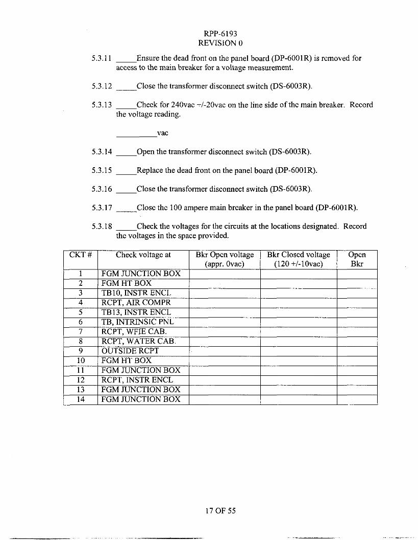
5.3.11 ~ Ensure the dead front on the panel board (DP-6001R) is removed for access to the main breaker for a voltage measurement.
5.3.12 ~ Close the transformer disconnect switch (DS-6003R).
5.3.13 ~ Check for 240vac +/-20vac on the line side of the main breaker. Record the voltage reading.
vac
5.3.14 ___ Open the transformer disconnect switch (DS-6003R).
5.3.15 ~ Replace the dead front on the panel board (DP-6001R).
5.3.16 ~ Close the transformer disconnect switch (DS-6003R).
5.3.17 ___ Close the 100 ampere main breaker in the panel board (DP-6001R).
5.3.18 - Check the voltages for the circuits at the locations designated. Record the voltages in the space provided.
17 OF 55
RPP-6193 REVISION 0
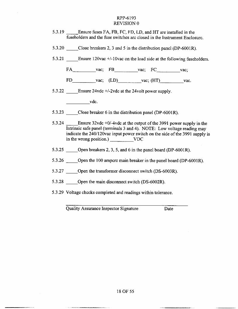
5.3.19 -Ensure fuses FA, FB, FC, FD, LD, and HT are installed in the fuseholders and the fuse switches are closed in the Instrument Enclosure.
5.3.20 -Close breakers 2 ,3 and 5 in the distribution panel (DP-6001R).
5.3.21 ~ Ensure 120vac +/-lOvac on the load side at the following hseholders.
FA vac; FB vac; FC vac;
FD vac; (LD) vac; (HT) vac.
5.3.22 ~ Ensure 24vdc +/-2vdc at the 24volt power supply.
vdc.
5.3.23 -Close breaker 6 in the distribution panel (DP-6001R).
5.3.24 - Ensure 32vdc +0/-4vdc at the output of the 3991 power supply in the Intrinsic safe panel (terminals 3 and 4). NOTE: Low voltage reading may indicate the 240/120vac input power switch on the side of the 3991 supply is in the wrong position.) VDC
5.3.25 ~ Open breakers 2,3,5, and 6 in the panel board (DP-6001R).
5.3.26 - Open the 100 ampere main breaker in the panel board (DP-6001R).
5.3.27 - Open the transformer disconnect switch (DS-6003R).
5.3.28 ~ Open the main disconnect switch (DS-6002R).
5.3.29 Voltage checks completed and readings within tolerance.
Quality Assurance Inspector Signature Date
18 OF 55
RPP-6193 REVISION 0
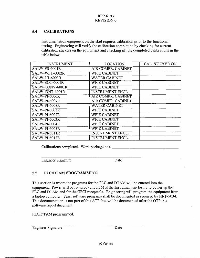
5.4 CALIBRATIONS
Instrumentation equipment on the skid requires calibration prior to the functional testing. Engineering will verify the calibration completion by checking for current calibration stickers on the equipment and checking off the completed calibrations in the table below.
Calibrations completed. Work package nos.
Engineer Signature Date
5.5 PLC/DTAM PROGRAMMING
This section is where the programs for the PLC and DTAM will be entered into the equipment. Power will be required (circuit 5) at the Instrument enclosure to power up the PLC and DTAM and for the GFCI receptacle. Engineering will program the equipment from a laptop computer. Final software programs shall be documented as required by HNF-5034. This documentation is not part of this ATP, but will be documented after the OTP in a software report document.
PLC/DTAM programmed.
Engineer Signature Date
RPP-6193 REVISION 0
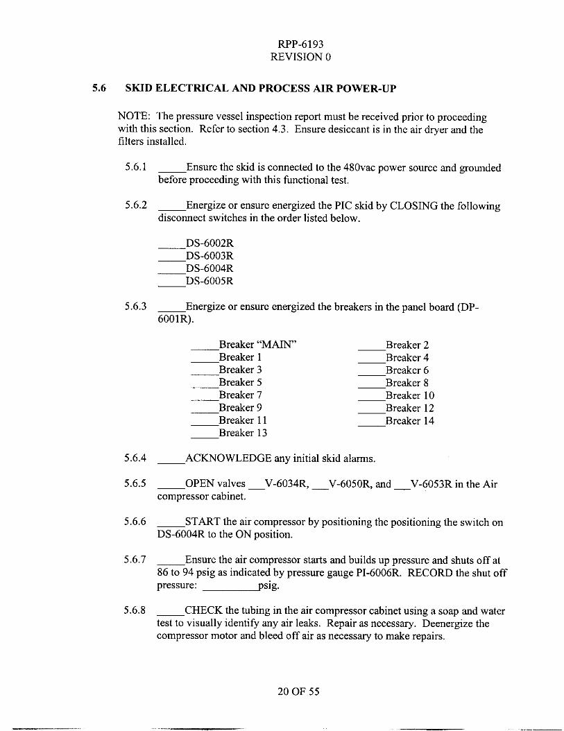
5.6 SKID ELECTRICAL AND PROCESS AIR POWER-UP
NOTE: The pressure vessel inspection report must be received prior to proceeding with this section. Refer to section 4.3. Ensure desiccant is in the air dryer and the filters installed.
5.6.1 - Ensure the skid is connected to the 48Ovac power source and grounded before proceeding with this functional test.
~ Energize or ensure energized the PIC skid by CLOSING the following disconnect switches in the order listed below.
5.6.2
5.6.3 ~ Energize or ensure energized the breakers in the panel board (DP- 6001R).
-Breaker “MAIN” -Breaker 2 Breaker 1 -Breaker 4
-Breaker 3 -Breaker 6 -Breaker 5 -Breaker 8 -Breaker 7 -Breaker 10 -Breaker 9 -Breaker 12
Breaker 11 -Breaker 14 Breaker 13
5.6.4 - ACKNOWLEDGE any initial skid alarms.
5.6.5 - OPEN valves -V-6034R, - V-6050R, and - V-6053R in the Air compressor cabinet.
- START the air compressor by positioning the positioning the switch on DS-6004R to the ON position.
5.6.7 ___ Ensure the air compressor starts and builds up pressure and shuts off at 86 to 94 psig as indicated by pressure gauge PI-6006R. RECORD the shut off pressure: psig.
5.6.8 - CHECK the tubing in the air compressor cabinet using a soap and water test to visually identify any air leaks. Repair as necessary. Deenergize the compressor motor and bleed off air as necessaty to make repairs.
5.6.6
20 OF 55
RPP-6193 REVISION 0
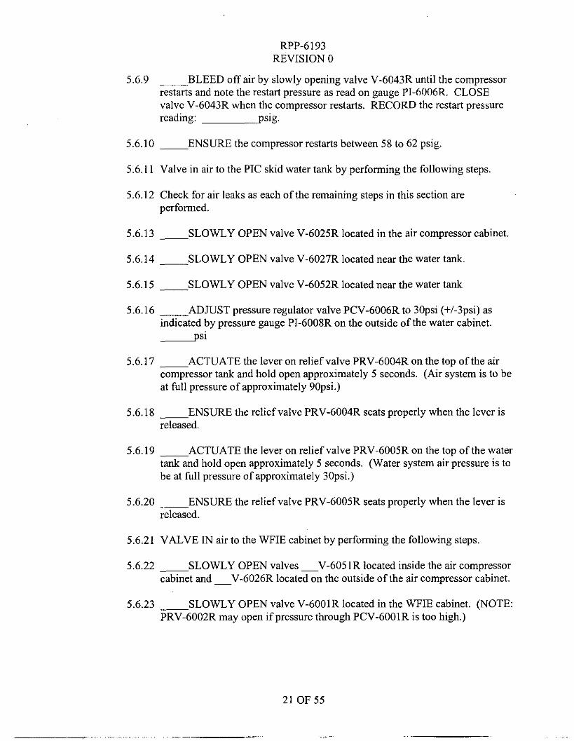
5.6.9 ~ BLEED off air by slowly opening valve V-6043R until the compressor restarts and note the restart pressure as read on gauge PI-6006R. CLOSE valve V-6043R when the compressor restarts. RECORD the restart pressure reading: psig.
5.6.10 - ENSURE the compressor restarts between 58 to 62 psig
5.6.1 1 Valve in air to the PIC skid water tank by performing the following steps
5.6.12 Check for air leaks as each ofthe remaining steps in this section are performed.
5.6.13 - SLOWLY OPEN valve V-6025R located in the air compressor cabinet.
5.6.14 - SLOWLY OPEN valve V-6027R located near the water tank.
5.6.15 ~ SLOWLY OPEN valve V-6052R located near the water tank
5.6.16 ___ ADJUST pressure regulator valve PCV-6006R to 3Opsi (+/-3psi) as indicated by pressure gauge PI-6008R on the outside of the water cabinet.
psi
5.6.17 - ACTUATE the lever on relief valve PRV-6004R on the top of the air compressor tank and hold open approximately 5 seconds. (Air system is to be at full pressure of approximately 9Opsi.)
5.6.18 ENSURE the relief valve PRV-6004R seats properly when the lever is released.
5.6.19 - ACTUATE the lever on relief valve PRV-6005R on the top of the water tank and hold open approximately 5 seconds. (Water system air pressure is to be at full pressure of approximately 3Opsi.)
5.6.20 ___ ENSURE the relief valve PRV-6005R seats properly when the lever is released.
5.6.21 VALVE IN air to the WFIE cabinet by performing the following steps.
5.6.22 - SLOWLY OPEN valves -V-6051R located inside the air compressor cabinet and -V-6026R located on the outside of the air compressor cabinet.
5.6.23 ___ SLOWLY OPEN valve V-6001R located in the WFIE cabinet. (NOTE: PRV-6002R may open if pressure through PCV-6001R is too high.)
21 OF 55
._ - --
RPP-6193 REVISION 0
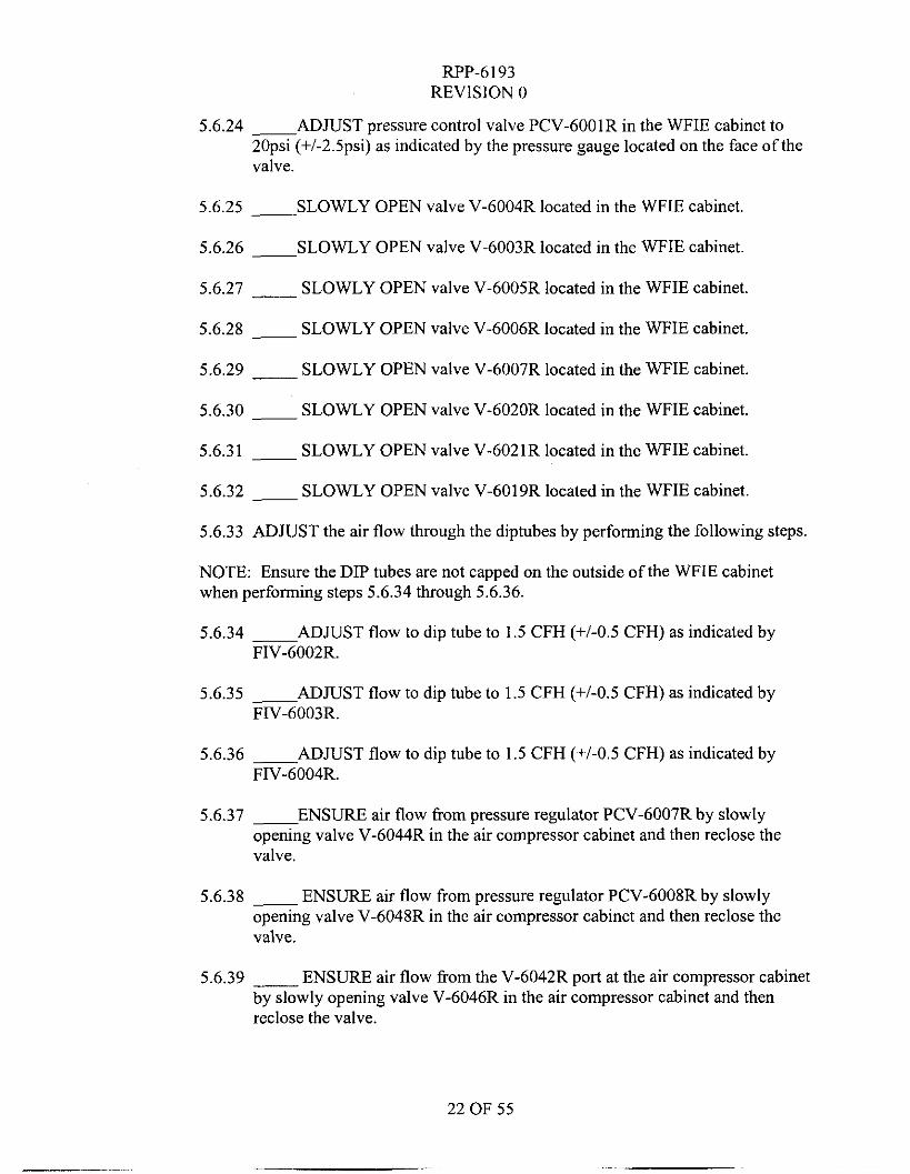
5.6.24 - ADJUST pressure control valve PCV-6001R in the WFIE cabinet to 2Opsi (+/-2.5psi) as indicated by the pressure gauge located on the face of the valve.
5.6.25 ~ SLOWLY OPEN valve V-6004R located in the WFIE cabinet.
5.6.26 - SLOWLY OPEN valve V-6003R located in the WFIE cabinet
5.6.27 __ SLOWLY OPEN valve V-6005R located in the WFIE cabinet.
5.6.28 - SLOWLY OPEN valve V-6006R located in the WFIE cabinet.
5.6.29 ___ SLOWLY OPEN valve V-6007R located in the WFIE cabinet.
5.6.30 - SLOWLY OPEN valve V-6020R located in the WFIE cabinet.
5.6.31 - SLOWLY OPEN valve V-6021R located in the WFIE cabinet
5.6.32 - SLOWLY OPEN valve V-6019R located in the WFIE cabinet
5.6.33 ADJUST the air flow through the diptubes by performing the following steps.
NOTE: Ensure the DIP tubes are not capped on the outside of the WFIE cabinet when performing steps 5.6.34 through 5.6.36.
5.6.34 - ADJUST flow to dip tube to 1.5 CFH (+/-OS CFH) as indicated by FIV-6002R.
5.6.35 - ADJUST flow to dip tube to 1.5 CFH (+/-0.5 CFH) as indicated by FIV-6003R.
5.6.36 __ ADJUST flow to dip tube to 1.5 CFH (+/-0.5 CFH) as indicated by FIV-6004R.
5.6.37 - ENSURE air flow !?om pressure regulator PCV-6007R by slowly opening valve V-6044R in the air compressor cabinet and then reclose the valve.
5.6.38 - ENSURE air flow from pressure regulator PCV-6008R by slowly opening valve V-6048R in the air compressor cabinet and then reclose the valve.
5.6.39 ____ ENSURE air flow from the V-6042R port at the air compressor cabinet by slowly opening valve V-6046R in the air compressor cabinet and then reclose the valve.
22 OF 55
RPP-6 193 REVISION 0
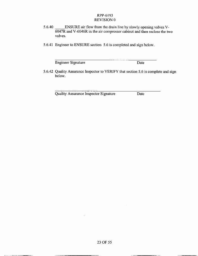
5.6.40 ~ ENSURE air flow from the drain line by slowly opening valves V- 6047R and V-6046R in the air compressor cabinet and then reclose the two valves.
5.6.41 Engineer to ENSURE section 5.6 is completed and sign below,
Engineer Signature Date
5.6.42 Quality Assurance Inspector to VERIFY that section 5.6 is complete and sign below.
Quality Assurance Inspector Signature Date
23 OF 55
RPP-6193 REVISION 0
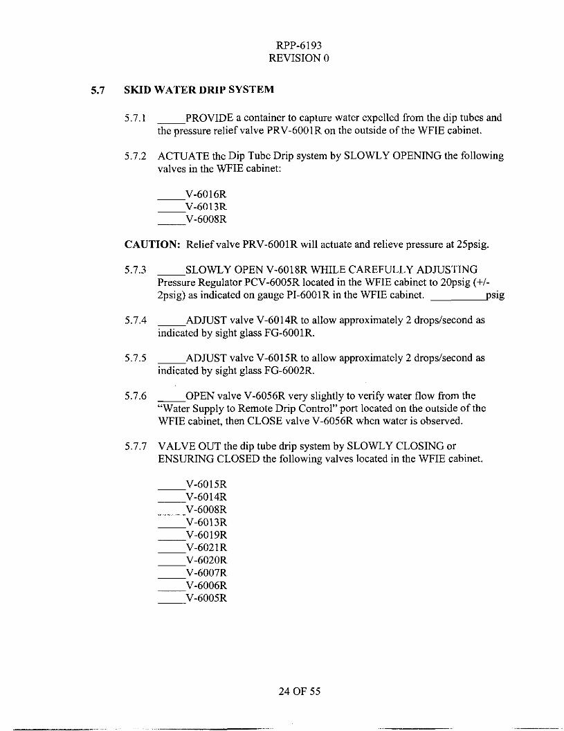
5.7 SKID WATER DRIP SYSTEM
5.7.1 PROVIDE a container to capture water expelled from the dip tubes and the pressure relief valve PRV-6001R on the outside of the WFIE cabinet.
ACTUATE the Dip Tube Drip system by SLOWLY OPENING the following valves in the WFIE cabinet:
5.7.2
V-6016R V - 6 0 1 3 R -V-6008R
CAUTION: Relief valve PRV-6001R will actuate and relieve pressure at 25psig.
5.7.3
5.7.4
5.7.5
5.7.6
5.7.7
-SLOWLY OPEN V-6018R WHILE CAREFULLY ADJUSTING Pressure Regulator PCV-6005R located in the WFIE cabinet to 2Opsig (+I- 2psig) as indicated on gauge PI-6001R in the WFIE cabinet. psig
ADJUST valve V-6014R to allow approximately 2 dropskecond as indicated by sight glass FG-6001R.
-ADJUST valve V-6015R to allow approximately 2 dropsIsecond as indicated by sight glass FG-6002R.
OPEN valve V-6056R very slightly to verify water flow from the “Water Supply to Remote Drip Control” port located on the outside of the WFIE cabinet, then CLOSE valve V-6056R when water is observed.
VALVE OUT the dip tube drip system by SLOWLY CLOSING or ENSURING CLOSED the following valves located in the WFIE cabinet.
V-6015R V-60 14R
V-6013R
V-6021R V-6020R
-V-6007R
-V-6008R
V-6019R
-V-6006R -V-6005R
24 OF 55
RPP-6193 REVISION 0
Engineer to ENSURE section 5.7 is completed and sign below. 5.7.8
Engineer Signature Date
Quality Assurance Inspector to VERIFY that section 5.7 is complete and sign below.
5.7.9
Quality Assurance Inspector Signature Date
25 OF 55
RPP-6193 REVISION 0
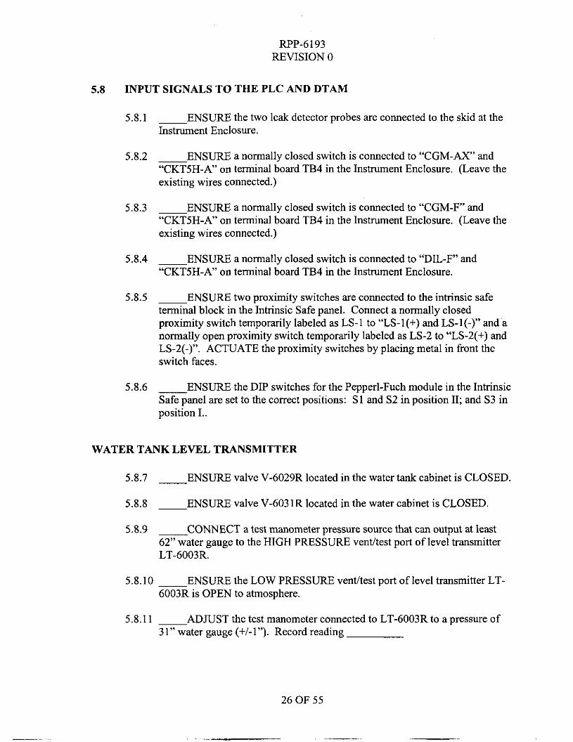
5.8 INPUT SIGNALS TO THE PLC AND DTAM
5.8.1 ~ ENSURE the two leak detector probes are connected to the skid at the Instrument Enclosure.
5.8.2 ~ ENSURF a normally closed switch is connected to “CGM-AX” and “CKTSH-A” on terminal board TB4 in the Instrument Enclosure. (Leave the existing wires connected.)
~ ENSURE a normally closed switch is connected to “CGM-F” and “CKT5H-A” on terminal board TB4 in the Instrument Enclosure. (Leave the existing wires connected.)
5.8.4 ~ ENSURE a normally closed switch is connected to “DIL-F” and “CKTSH-A” on terminal board TB4 in the Instrument Enclosure.
5.8.5 ~ ENSURE two proximity switches are connected to the intrinsic safe terminal block in the Intrinsic Safe panel. Connect a normally closed proximity switch temporarily labeled as LS-1 to “LS-I(+) and LS-I(-)” and a normally open proximity switch temporarily labeled as LS-2 to “LS-2(+) and LS-2(-)”. ACTUATE the proximity switches by placing metal in front the switch faces.
5.8.3
5.8.6 __ ENSURE the DIP switches for the Pepperl-Fuch module in the Intrinsic Safe panel are set to the correct positions: S1 and S2 in position 11; and S3 in position I..
WATER TANK LEVEL TRANSMITTER
5.8.7 - ENSURE valve V-6029R located in the water tank cabinet is CLOSED.
5.8.8 ~ ENSURE valve V-603 1R located in the water cabinet is CLOSED.
5.8.9 - CONNECT a test manometer pressure source that can output at least 62” water gauge to the HIGH PRESSURE venthest port of level transmitter LT-6003R.
5.8.10 ~ ENSURE the LOW PRESSURE vent/test port of level transmitter LT- 6003R is OPEN to atmosphere.
5.8.11 ~ ADJUST the test manometer connected to LT-6003R to a pressure of 31” water gauge (+/-1”). Record reading
26 OF 55
RPP-6193 REVISION 0
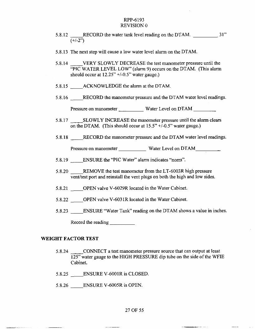
5.8.12 __ RECORD the water tank level reading on the DTAM. (+/-2”)
31”
5.8.13 The next step will cause a low water level alarm on the DTAM
5.8.14 __ VERY SLOWLY DECREASE the test manometer pressure until the “PIC WATER LEVEL L O W (alarm 9) occurs on the DTAM. (This alarm should occur at 12.25” +/-OS” water gauge.)
5.8.15 - ACKNOWLEDGE the alarm at the DTAM.
5.8.16 __ RECORD the manometer pressure and the DTAM water level readings.
Pressure on manometer Water Level on DTAM
5.8.17 __ SLOWLY INCREASE the manometer pressure until the alarm clears on the DTAM. (This should occur at 15.5” +/-OS” water gauge.)
5.8.18 __ RECORD the manometer pressure and the DTAM water level readings.
Pressure on manometer Water Level on DTAM
5.8.19 ___ ENSURE the “PIC Water” alarm indicates ‘‘nomi”
5.8.20 - REMOVE the test manometer from the LT-6003R high pressure vent/test port and reinstall the vent plugs on both the high and low sides.
5.8.21 - OPEN valve V-6029R located in the Water Cabinet.
5.8.22 - OPEN valve V-6031R located in the Water Cabinet.
5.8.23 - ENSURE “Water Tank” reading on the DTAM shows a value in inches.
Record the reading
WEIGHT FACTOR TEST
5.8.24 __ CONNECT a test manometer pressure source that can output at least 125” water gauge to the HIGH PRESSURE dip tube on the side of the WFIE Cabinet.
5.8.25 - ENSURE V-6001R is CLOSED.
5.8.26 - ENSURE V-6005R is OPEN.
27 OF 55
RPP-6193 REVISION 0
5.8.27 ~ ENSURE V-6006R is OPEN,
5.8.28 ~ ENSURE adjustment valves on FIV-6002R, FIV-6003R and FIV- 6004R are CLOSED.
5.8.29 ~ ENSURE the LOW and HIGH side isolation valves located on the V- 6036R 3-Valve manifold in the WFIE cabinet are OPEN.
5.8.30 ~ ENSURE the EQUALIZING valve located on the V-6036R 3-Valve manifold in the WFIE cabinet is CLOSED.
5.8.31 ~ SET the test manometer to 125” (+/-1”) water gauge. Record the manometer reading.
5.8.32 __ RECORD the “WFT” reading on the DTAM. The reading is to be 125” (+/- 5”).
5.8.33 ~ BLEED off the pressure on the test manometer. Leave connected for testing the specific gravity transmitter.
5.8.34 ___ CLOSE V-6006R.
5.8.35 __ OPEN the EQUALIZING valve located on V-6036R 3-Valve manifold in the WFIE cabinet.
5.8.36 ~ CLOSE the LOW and HIGH side isolation valves located on the V- 6036R 3-Valve manifold in the WFIE cabinet.
SPECIFIC GRAVITY TRANSMITTER
5.8.37 ___ ENSURE V-6007R is OPEN.
5.8.38 ~ ENSURE V-6005R is OPEN.
5.8.39 __ ENSURE the LOW and HIGH side isolation valves located on V- 6035R 3-Valve manifold in the WFIE cabinet are OPEN.
5.8.40 ~ ENSURE the specific gravity transmitter equalizing valve located on the V-6035R 3-Valve manifold located in the WFIE cabinet is CLOSED.
5.8.41 - SET the test manometer to 5”water gauge (+/- 0.3”).
5.8.42 __ RECORD the “SGT” reading on the DTAM. Reading to be 5” +/- 0.35”.
RPP-6193 REVISION 0
5.8.43 ~ BLEED off pressure on the manometer.
5.8.44 ~ ENSURE “SGT L O W alarm occurs (alarm 13).
5.8.45 ___ ACKNOWLEDGE the alarm.
5.8.46 ~ DISCONNECT the test manometer.
5.8.47 ~ CLOSE V-6007R.
5.8.48 ~ CLOSE V-6005R
5.8.49 ~ OPEN the EQUALIZING valve located on V-6035R 3-Valve manifold in the WFIE cabinet.
5.8.50 - CLOSE the LOW side and HIGH side isolation valves located on V- 6035R 3-Valve manifold in the WFIE cabinet.
FLOW METER SIGNAL CHECK
5.8.51 ~ Prepare the flow converter FQIT-6001R located in the Instrument Enclosure to simulate a flow either using the buttons on the front face or using a “brain terminal”.
5.8.52 SIMULATE a flow signal of 7.0gpm (50% span) with the hand-held brain terminal or from the flow converter face switches.
5.8.53 ~ RECORD the flow readings on the kont of the flow converter and on the DTAM (PMP FLOW). Readings to be 7.0 +/- 0.4 gpm.
Flow converter DTAM (PMP FLOW)
5.8.54 - RESTORE the flow converter, FQIT-6001R to its original configuration.
29 OF 55
_. .
RPP-6193 REVISION 0
SUCTION AND DISCHARGE PRESSURE SIGNAL
5.8.55 ~ ENSURE a current source is connected to PSPT+ and PSPT- on the intrinsic side terminal board in the Intrinsic Safe panel. Set the source to “transmitter simulate.”
5.8.56 ~ SET the current source to approximately 4mA and record the suction pressure reading on PI-6012R. Reading to be approximately zero.
psi
5.8.57 - SET the current source to approximately 20mA and record the suction pressure reading on PI-6012R. Reading to be approximately 1OOpsi.
psi
5.8.58 ~ DISCONNECT the current source.
5.8.59 ~ ENSURE a current source is connected to PDPT+ and PDPT- at the intrinsic side terminal board in the Intrinsic Safe panel. Set the source to transmitter simulate.
5.8.60 - SET the current source to approximately 4mA and record the discharge pressures on PI-601 1R and on the DTAM. Readings should be approximately zero.
PI-601 1R psi DTAM (PMP DISC) psi
5.8.61 - SET the current source to approximately 20mA and record the discharge pressures on PI-601 1R and on the DTAM. Readings should be approximately 30Opsi.
PI-601 1R psi DTAM (PMP DISC) psi
5.8.62 - DISCONNECT the current source.
COMBUSTIBLE GAS MONITOR ANALOG SIGNAL TO PLC
5.8.63 ~ ENSURE a current source is connected to the CGM loop by lifting the CGM O(+) wire going to the CGM transmitter at terminal board TB1 in the Instrument Enclosure, and connecting the current source between CGM O(+) at TBl and the lifted CGM O(+) wire.
5.8.64 ~ SET the current source to approximately 4mA.
30 OF 55
RPP-6 193 REVISION 0
5.8.65 - RECORD the “CGM’ percent reading from the DTAM. Reading is to be approximately zero. %
5.8.66 ~ SET the current source to approximately 12mA.
5.8.67 __ RECORD the “ C G M percent reading from the DTAM. Reading is to be approximately 50%. %
5.8.68 ~ SET the current source to approximately 20mA.
5.8.69 ___ RECORD the “ C G M percent reading from the DTAM. Reading is to be approximately 100%. %
5.8.70 ~ DISCONNECT the current source and reconnect the CGM O(+) wire to TB1.
DOME SPACE FLAMMABLE GAS MONITOR ANALOG SIGNAL TO PLC
5.8.71 __ ENSURE a current source is connected to terminal board TB1 in the Instrument Enclosure, points FGM I(+) and FGM I(-)
5.8.72 - SET the current source to approximately 4mA.
5.8.73 - RECORD the “FGM’ percent reading from the DTAM. Reading is to be approximately zero. %
5.8.74 ~ SET the current source to approximately 12mA.
5.8.75 ~ RECORD the “FGM’ percent reading from the DTAM. Reading is to be approximately 50%. %
5.8.76 - SET the current source to approximately 20mA.
5.8.77 ~ RECORD the “FGM’ percent reading from the DTAM. Reading is to be approximately 100%. %
5.8.78 - DISCONNECT the current source.
THERMOCOUPLE INPUTS TO THE PLC
5.8.79 ~ WARM thermocouple TE-6004R located in the Instrument Enclosure.
5.8.80 - ENSURE the “PLC CAB temp” on the DTAM displays a temperature change.
31 OF 55
RF’P-6193 REVISION 0
5.8.81 ~ CONTINUE to warm the thermocouple until “PLC Enclosure HI” (alarm 10) occurs. This will be approximately 130 degrees F.
5.8.82 ~ ACKNOWLEDGE the alarm
5.8.83 ~ ENSURE “PLC CAB temp” on the DTAM shows a temperature DECREASE after the heat source is removed from the TE-6004R thermocouple.
5.8.84 ~ ENSURE the “PLC temp” alarm returns to “norm” when the temperature decreases below 125 degrees F.
5.8.85 __ WARM thermocouple TE-6003R located in the Air Compressor Cabinet.
5.8.86 ~ ENSURE the “COMPRS temp” on the DTAM displays a temperature change.
5.8.87 ~ CONTINUE to warm the thermocouple until “Air Compressor Temp HI” (alarm 11) occurs. This will be approximately 130 degrees F.
5.8.88 ~ ACKNOWLEDGE the alarm.
5.8.89 ___ ENSURE “COMPRS temp” on the DTAM shows a temperature DECREASE after the heat source is removed from the TE-6003R thermocouple.
5.8.90 ~ ENSURE the “CMPRSR temp” alarm returns to “norm” when the temperature decreases below 125 degrees F.
5.8.91 ~ COOL the thermocouple probe in the WFIE cabinet using ice water or cool air spray. Temperature needs to drop below 35 degrees F.
5.8.92 __ ENSURE alarm 50, “WFIE CAB Temp Low” occurs at the DTAM.
5.8.93 ~ WARM or ALLOW to warm the thermocouple probe in the WFIE cabinet and ENSURE the “WFIE CAB Temp” alarm is “norm” when the temperature goes above 40 degrees F.
5.8.94 ~ COOL the thermocouple probe in the Water cabinet using ice water or cool air spray. Temperature needs to drop below 35 degrees F.
5.8.95 ~ ENSURE alarm 49, “WATER CAB Temp Low” occurs at the DTAM.
32 OF 55
RPP-6 193 REVISION 0
5.8.96 ~ WARM or ALLOW to warm the thermocouple probe in the Water cabinet and ENSURE the “WATER CAB Temp” alarm is “norm” when the temperature goes above 40 degrees F.
5.8.97 ~ CONNECT two temperature simulators to the intrinsic side of the two thermocouple modules (MTL 3081) in the Intrinsic Safe panel.
5.8.98 ~ SET the motor temperature alarm setpoints at the DTAM to 125 degrees F for the high and 135 degrees F for the high high. NOTE: The security code is 11 for the restricted screen for entry.
5.8.99 ~ SET both temperature simulators to approximately 120 degrees F.
5.8.1 00- ENSURE the “PUMP temp” and the “JMPER TEMP” each read approximately 120 degree at the DTAM. (Pump) (Jumper)
5.8.101- ENSURE the “Jmp Htr” is ON at the DTAM.
5.8.102- DECREASE the temperature simulator on the top module to approximately 39 degrees or lower until alarm 8 “Pump/Jumper Temp Trouble” alarms on the DTAM.
5.8.103- ACKNOWLEDGE the alarm.
5.8.1 04- ENSURE the “PUMP TEMP” reads approximately 39 degree at the DTAM.
5.8.105- INCREASE the temperature simulator on the top module to approximately 120 degrees.
5 3.106- ENSURE the “JMPR HT” alarm on the DTAM reads “norm”.
5.8.1 07- ENSURE the “Jmp Htr” is ON at the DTAM.
5.8.1 08- ENSURE the switches installed on TB4 between points “CGM-AX” and “CKT5H-A”; and “CGM-F” and “CKT5H-A” are in the CLOSED position.
5.8.1 09- ENSURE approximately 120vac between HT-1 and CKT3-N at TB12. vac
5.8.1 1 0- WHILE MONITORING the voltage at TB12, INCREASE the temperature on the second module to 206 degrees F or higher until the voltage at TB12 goes to approximately zero. DTAM temp.
33 OF 55
- __
RPP-6193 REVISION 0
5.8.111- WHILE MONITORING the voltage at TB 12, decrease the temperature on the second module to 194 degrees F or lower until the voltage at TB12 goes to approximately 12Ovac. DTAM temp.
5.8.1 12- OPEN the switch on TB4 that is across “CGM-AX” and “CKT5H-A”
5.8.113- ENSURE alarm “25” occurs and ACKNOWLEDGE.
5.8.1 14- ENSURE the voltage at TB12 goes to approximately zero
5.8.1 15- CLOSE the switch on TB4 that is across “CGM-AX” and “CKT5H-A”.
5.8.116- ENSURE the voltage at TB12 returns to approximately 120vac.
5.8.117- OPEN the switch on TB4 that is across “CGM-F” and “CKT5H-A”.
5.8.118- ENSURE alarm “31” occurs and ACKNOWLEDGE.
5.8.119- ENSURE the voltage at TB12 goes to approximately zero.
5.8.120- CLOSE the switch on TB4 that is across “CGM-F” and “CKT5H-A”
5.8.121- ENSURE the voltage at TB12 returns to approximately 120vac.
5.8.122- TURN OFF the heat trace from the DTAM.
5.8.123- ENSURE the voltage at TB12 goes to approximately zero.
5.8.124- TURN ON the heat trace from the DTAM
5.8.125- ENSURE the voltage at TB12 returns to approximately 120vac.
5.8.126- INCREASE the temperature simulator on the second module to approximately 226 degrees or higher until alarm 8 “Pump/Jumper Temp Trouble” alarms on the DTAM.
5.8.127- ACKNOWLEDGE the alarm.
5.8.128- DECREASE the temperature simulator on the second module to less than 225 degrees.
5.8.129- ENSURE the “JMPR HT” alarm 8 returns to “norm” on the DTAM.
5.8.130- REMOVE the temperature simulator from the bottom module, but leave the top temperature simulator connected for the interlock checks in section 5.9.
34 OF 55
WP-6193 REVISION 0
5.8.131Engineer to Ensure section 5.8 is completed and sign below.
Engineer Signature Date
5.8.132Quality Assurance Inspector to Verify that section 5.8 is complete and sign below.
Quality Assurance Inspector Signature Date
RPP-6193 REVISION 0
5.9 JET PUMP INTERLOCK CIRCUITS
5.9.1 __ ENSURE the LS-1 and LS-2 proximity switches at the Intrinsic safe panel; the two leak detector probes; the two CGM, the Dilution, and the AX101 switches at TB4 in the Instrument Enclosure are in place as per steps 5.8.1 to 5.8.6.
5.9.2 ~ IF POSSIBLE, CONNECT three current sources to the following points. One to JFPT+ and JFPT-in the Intrinsic Safe panel at the intrinsic terminal board; one to RFPT+ and RFPT- in the Instrument Enclosure at TB2; and one to PXPT+ and PXPT- at the intrinsic terminal board in the Intrinsic safe panel. Set the current sources to “transmitter simulate” and at 6mA. NOTE: If three current sources are not available, then software forces will be used during this section to bypass the inputs not being tested.
5.9.3 ~ SET the temperature simulator at the Intrinsic Safe panel to 120 degrees F.
5.9.4 ~ ENSURE the temperature setpoint for the motor-bearing temperature high-alarm is set to 125 degrees F and the high-high-alarm is set to 135 degrees F.
~ CONNECT the laptop computer to the PLC to set forces and observe logic when required.
5.9.6 ~ RECORD the reading of the Hourmeter on the front of the Instrument Enclosure.
5.9.5
RECIRCULATION FLUSH PRESSURE SIGNAL TO PLC
5.9.7 - ENSURE a current source is connected to points RFPT+ and RF’PT- in the Instrument Enclosure at TB2 and is set to approximately 6mA.
5.9.8 ~ ENSURE the green light on the Instrument Enclosure and on the Jet Pump motor starter are ON.
~ APPLY software forces to allow the jet pump to start. (Engineering will apply the forces from the laptop computer connected to the PLC. Normally this will be the COMM Failure and any leak station interlocks. These can be forced out by setting the timers to a high set value such as 7200 seconds with the laptop on-line. If the timers need to be reset to start counting, this is done by turning the key switch on the PLC from “RUN” to “PROGRAM’ and then back to “RUN”.)
5.9.9
5.9.10 ~ TURN the selector switch on the Jet Pump Motor Starter to ON.
36 OF 55
RPP-6193 REVISION 0
5.9.11 START the jet pump from the DTAM and OBSERVE that the red lights at the Instrument Enclosure and motor starter come ON and the green lights at both locations turn OFF.
5.9.12 SLOWLY INCREASE the current source output to approximately 12.5mA or until the pump shuts down after a 3 second delay. OBSERVE the following: (Acknowledge the alarms as necessary to observe all the alarms.) NOTE: The horn sound can be adjusted by turning the set screw on the front of the horn for sound level as directed by the engineer or PIC.
-Record current reading on current source. -The strobe light flashes and the horn sounds. -Alarm 12 occurs, “JET PUMP SHUTDOWN’’. -Alarm 39 occurs, “RECIRC FLUSH PRESS HI”. -Red lights at the motor starter and Instrument Enclosure are OFF. -Green lights at the motor starter and Instrument Enclosure are ON. -The “RECR FL P R is approximately 15psi. psi -Ensure addresses N20:32/2 and N20:32/6 are actuated as observed on the laptop computer in ladder 5.
mA
5.9.13 DECREASE the current source to approximately 4mA.
5.9.14 ~ ENSURE the “Recirc Press” alarm at the DTAM returns to “norm”.
5.9.15
5.9.16
ENSURE address N20:32/6 clears as observed on the laptop.
START the jet pump from the DTAM and OBSERVE that the red lights at the Instrument Enclosure and motor starter come ON and the green lights at both locations turn OFF.
5.9.17 -DECREASE the current source to zero.
5.9.18 ~ ENSURE the jet pump shuts down.
5.9.19
5.9.20 ~ ACKNOWLEDGE the alarm.
5.9.21 ~ ENSURE address N20:32/7 is actuated as observed on the laptop.
5.9.22
5.9.23 __ ENSURE the “RFPT SIGNAL” alarm returns to “norm” on the DTAM.
5.9.24
ENSURE alarm 14, “RFPT SIGNAL LOSS ALARM” occurs
INCREASE the current source to approximately 6mA.
ENSURE address N20:32/7 clears as observed on the laptop.
37 OF 55
FWP-6193 REVISION 0
JUMPER FLUSH PRESSURE SIGNAL TO PLC
5.9.25 ENSURE a current source is connected to points JFPT+ and JFPT- in the Intrinsic Safe panel intrinsic terminal board and is set to approximately 6mA.
5.9.26 ENSURE the green light on the Instrument Enclosure and on the Jet Pump motor starter are ON.
5.9.27 APPLY software forces as necessary to allow the jet pump to start. (Engineering will apply the forces from the laptop computer connected to the PLC.)
5.9.28 ~ START the jet pump from the DTAM and OBSERVE that the red lights at the Instrument Enclosure and motor starter come ON and the green lights at both locations turn OFF.
5.9.29
5.9.30
ENSURE address N20:32/2 is clear as observed on the laptop.
SLOWLY INCREASE the current source output to approximately 12.5mA or until the pump shuts down after a 3 second delay. OBSERVE the following: (Acknowledge the alarms as necessary to observe all the alarms.)
-The jet pump shuts down. -Record current reading on current source. mA
Alarm 3 occurs, “Flush Pressure HI”. Alarm 12 occurs, “JET PUMP SHUTDOWN”.
-Blue light at the Instrument Enclosure is ON. -The “PS2 FL PR’ is approximately 15psi. psi -Ensure address N20:32/5 is actuated as observed on the laptop.
DECREASE the current source to approximately 4mA.
ENSURE the “Flush Press” alarm at the DTAM returns to “norm”
ENSURE the blue light at the Instrument Enclosure turns OFF.
ENSURE address N20:32/5 clears as observed on the laptop
START the jet pump from the DTAM.
DECREASE the current source to zero.
5.9.31
5.9.32
5.9.33
5.9.34
5.9.35
5.9.36
5.9.37 __ ENSURE the jet pump shuts down.
5.9.38 ENSURE alarm 16, “JFPT SIGNAL LOSS ALARM” occurs.
38 OF 55
RPP-6193 REVISION 0
5.9.39 ~ ACKNOWLEDGE the alarm.
5.9.40 ~ ENSURE address N20:32/8 actuates as observed on the laptop.
5.9.41
5.9.42 ~ ENSURE the “JFPT SIGNAL” alarm returns to “norm” on the DTAM.
5.9.43 __ ENSURE address N20:32/8 clears as observed on the laptop.
INCREASE the current source to approximately 6mA.
TRANSFER PRESSURE INTERLOCK INPUT
5.9.44 __ ENSURE a current source is connected to points PXPT+ and PXPT- in the Intrinsic Safe panel intrinsic terminal board and is set to approximately 6mA.
5.9.45 - ENSURE the laptop computer is connected to the PLC and is “on-line”.
5.9.46 - ENSURE the green light on the Instrument Enclosure and on the Jet Pump motor starter are ON.
5.9.47 __ APPLY software forces to allow the jet pump to start. (Engineering will apply the forces from the laptop computer connected to the PLC.)
5.9.48 ~ START the jet pump from the DTAM
5.9.49 ___ DECREASE the current source to approximately 4.8mA or until Timer 4.1 on the ladder logic of the PLC (rung 0 of ladder 5 ) starts timing.
5.9.50 - ENSURE the amber light on the Instrument Enclosure turns ON immediately after the timer starts.
5.9.51 ~ ENSURE after 30 seconds, the following occurs: (Acknowledge alarms as necessary to view all the alarms.)
-The jet pump shuts down. “XFR Pressure L O W (alarm 1) occurs at the DTAM. “JET PUMP SHUTDOWN” (alarml2) occurs at the DTAM
5.9.52 __ INCREASE the current source to approximately 6mA.
5.9.53 __ ENSURE the “XFR Pressure” alarm is “norm” on the DTAM.
5.9.54 ~ START the pump from the DTAM.
39 OF 55
RPP-6193 REVISION 0
5.9.55 INCREASE the current source to approximately 11.5mA or until Timer 4.2 on rung 2 of ladder 5 starts timing as observed on the laptop computer.
5.9.56 __ ENSURE after a 3 second delay, the following occurs: (Acknowledge alarms as necessary to view all the alarms.)
-The jet pump shuts down. ~ “XFR Pressure HIGH’ (alarm 2) occurs at the DTAM.
“JET PUMP SHUTDOWN” (alarml2) occurs at the DTAM.
DECREASE the current source to approximately 6mA.
ENSURE the “XFR Pressure” alarm indicates “norm” on the DTAM.
5.9.57
5.9.58
JR-1 VALVE POSITION INPUT (LS-1 AND LS-2)
5.9.59 ~ START the pump from the DTAM.
5.9.60 ~ REMOVE the metal from the front face of LS-1.
5.9.61 __ ENSURE the following occurs immediately: (Acknowledge alarms as necessary to view all the alarms.)
-The jet pump shuts down.
~ “JET PUMP SHUTDOWN’’ (alarml2) occurs at the DTAM. -Address N20:32/0 on ladder 5 is actuated as observed on the laptop.
“JR-1 Position NON-PROCESS” (alarm 5) occurs at the DTAM.
5.9.62
5.9.63 ~ ENSURE the “JR-I” still indicates “NON-PROCESS” at the DTAM.
5.9.64 ~ ENSURE address N20:32/1 is actuated on ladder 5 as observed on the
REMOVE the metal form the front face of LS-2.
laptop.
5.9.65
5.9.66 ___ ENSURE the “JR-I” indicates “norm” on the DTAM and addresses
REPLACE the metal in front of LS-I and LS-2.
N20:32/0 and N20:32/1 are clear on ladder 5 as observed on the laptop.
COMBUSTIBLE GAS MONITOR INTERLOCK INPUTS
5.9.67
5.9.68
START the pump from the DTAM.
OPEN the CGM-AX switch at TB4.
40 OF 55
RPP-6193 REVISION 0
5.9.69 ENSURE the following occurs immediately: (Acknowledge alarms as necessary to view the alarms.)
-The jet pump shuts down. “JET PUMP SHUTDOWN” (alarml2) occurs at the DTAM. “HIGH LFL ON CGM’ (alarm 25) occurs at the DTAM.
CLOSE the CGM-AX switch at TB4.
ENSURE the “HI LFL CGM’ alarm indicates “norm” at the DTAM.
5.9.70
5.9.71
5.9.72 ___ START the pump from the DTAM.
5.9.73
5.9.74
OPEN the CGM-F switch at TB4.
ENSURE the following occurs after a 3-second delay: (Acknowledge alarms as necessary to view the alarms.)
-The jet pump shuts down. “JET PUMP SHUTDOWN” (alarml2) occurs at the DTAM. “CGM TROUBLE” (alarm 31) occurs at the DTAM.
CLOSE the CGM-F switch at TB4 5.9.75
5.9.76 ENSURE the “CGM TROUBLE” alarm indicates “norm” at the DTAM.
5.9.77
5.9.78
5.9.79 __ ENSURE the following occurs after a 5-minute delay: (Acknowledge
START the pump from the DTAM.
OPEN the dilution switch at TB4 in the Instrument Enclosure.
alarms as necessary to view the alarms.)
-The jet pump shuts down. “JET PUMP SHUTDOWN” (alarml2) occurs at the DTAM. “DILUTION TANK NO F L O W (alarm 35) occurs at the DTAM.
5.9.80 CLOSE the dilution switch.
5.9.81 ENSURE the “Dilution tk” alarm indicates “norm” on the DTAM
MOTOR HIGH TEMPERATURE
5.9.82 START the pump from the DTAM.
41 OF 55
RPP-6193 REVISION 0
5.9.83 INCREASE the temperature on the temperature simulator to approximately 126 degrees F or greater until alarm 58, “MOTOR TEMP H I G H actuates.
5.9.84 - INCREASE the temperature on the temperature simulator to approximately 136 degrees F or greater until the following occurs:
-The jet pump shuts down. ___ “JET PUMP SHUTDOWN” (alarml2) occurs at the DTAM. __ “Motor Temp Hi Shutdown” (alarm 59) occurs at the DTAM.
5.9.85 - DECREASE the temperature simulator to approximately 125 degrees F or lower until alarm “PMP HIHI TEMP” indicates “norm” at the DTAM.
5.9.86 ENSURE the “PMP HI TEMP” alarm indicates “norm” at the DTAM.
LEAK DETECTION INTERLOCK
5.9.87 ENSURE there is a water supply and bucket available to actuate the leak detector probes.
5.9.88
5.9.89
5.9.90 - ENSURE the following occurs after a 3-second delay: (Acknowledge
START the pump from the DTAM.
PLACE the primary leak detector probe in a bucket of water.
alarms as necessary to view the alarms.)
-The jet pump shuts down. ___“PUMP PIT LEAK” (alarm 6 ) occurs at the DTAM. __“JET PUMP SHUTDOWN” (alarml2) occurs at the DTAM. -The red light for the “Primary” leak detector is ON at the Instrument Enclosure. -Ensure address N20:32/3 in ladder 5 actuates as observed on the laptop.
5.9.91 __ REMOVE the leak detector probe from the bucket and allow the water to drain off.
5.9.92 ___ ENSURE the “Pump Pit” leak alarm returns to “norm”.
5.9.93 ~ ENSURE the red light for the “Primary” leak detector is OFF.
5.9.94 ENSURE address N20:32/3 clears as observed on the laptop.
42 OF 55
RF’P-6193 REVISION 0
5.9.95 - START the pump from the DTAM.
5.9.96 DISCONNECT one of the “SD’ wires going to the primary leak detector probe.
5.9.97 - ENSURE the following occurs after a 3-second delay: (Acknowledge alarms as necessary to view the alarms.)
-The jet pump shuts down. “PUMP PIT LEAK TROUBLE” (alarm 7) occurs at the DTAM. “JET PUMP SHUTDOWN” (alarml2) occurs at the DTAM.
-The red light for the “Primary” leak detector at the Instrument Enclosure is ON. -Ensure address N20:32/3 actuates as observed on the laptop.
5.9.98 __ RECONNECT the “SD’ wire.
5.9.99 - ENSURE the “Pump Pit” trouble alarm indicates “norm” on the DTAM.
5.9.100- ENSURE the red light for the “Primary” leak detector is OFF.
5.9.101- ENSURE address N20:32/3 clears as observed on the laptop.
5.9.1 02- START the pump from the DTAM.
5.9.1 03- PLACE the leak detector 1 probe in a bucket of water.
5.9.104- ENSURE the following occurs after a 3-second delay: (Acknowledge alarms as necessary to view the alarms.)
The jet pump shuts down. - “JET PUMP SHUTDOWN’’ (alarml2) occurs at the DTAM. ____ “LEAK DETECTOR NO 1 LEAK DETECTED’ (alarm 18) occurs at the DTAM. -The red light for “Leak Detector 1” at the Instrument Enclosure is ON. -Ensure address N20:32/4 actuates in ladder 5 as observed on the laptop.
5.9.105- REMOVE the leak detector probe from the bucket and allow the water to drain off.
5.9.106- ENSURE the “Leak 1” alarm returns to “norm”.
5.9.107- ENSURE the red light for “Leak Detector 1” is OFF.
5.9.10SPENSURE address N20:32/4 clears as observed on the laptop.
43 OF 55
RPP-6193 REVISION 0
5.9.109- START the pump from the DTAM.
5.9.110- DISCONNECT one of the “SD’ wires going to the leak detector 1 probe.
5.9.111- ENSURE the following occurs after a 3-second delay: (Acknowledge alarms as necessary to view the alarms.)
-The jet pump shuts down. -“JET PUMP SHUTDOWN’’ (alarml2) occurs at the DTAM. - “LEAK DETECTOR NO 1 TROUBLE” (alarm 19) occurs at the DTAM. -The red light for “Leak Detector 1” at the Instrument Enclosure is ON. -Ensure address N20:32/4 actuates as observed by the laptop.
5.9.112- RECONNECT the “ S D wire.
5.9.113- ENSURE the “Leak 1 CY’ alarm indicates “norm” on the DTAM.
5.9.1 14- ENSURE the red light for “Leak Detector 1” is OFF.
5.9.115- ENSURE address N20:32/4 clears as observed on the laptop.
5.9.1 16- RECORD the hourmeter reading.
5.9.117- VERIFY by comparing the readings in steps 5.9.6 and 5.9.108 that the hourmeter is recording time.
5.9.118- REMOVE the software forces and disconnect the laptop computer from the PLC.
5.9.119- TURN OFF breakers 2,3, 5, and 6 in the distribution panel.
5.9.120- DISCONNECT the current sources from the PWT, RFPT and JFPT termination points.
5.9.121- DISCONNECT the test switches from the CGM, FGM, and Dilution termination points.
5.9.122- DISCONNECT the proximity switches from the Intrinsic Safe panel.
5.9.123- DISCONNECT the leak detector probes from the Instrument Enclosure.
5.9.124- TURN ON breakers 2,3, 5, and 6 at the distribution panel.
44 OF 55
RPP-6193 REVISION 0
5.9.125Engineer to ENSURE section 5.9 is completed and sign below.
Engineer Signature Date
5.9.126Quality Assurance Inspector to VERIFY that section 5.9 is completed and sign below.
Quality Assurance Inspector Signature Date
WP-6193 REVISION 0
5.10 HEATERS, AIR CONDITIONER AND LIGHTS
5.10.1 ___ TURN the heater ON in the air compressor ce_..-et. Set the high enough to allow the unit to operate.
iermostat
5.10.2 RESET the thermostat to approximately 40 degrees F to allow the heat to turn OFF. Then unplug the heater.
5.10.3 TURN the fan thermostat switch to allow the fan in the air compressor cabinet to run.
5.10.4 __ RESET the fan switch to approximately 90 degrees F to allow the fan to turn OFF.
5.10.5 TURN the heater ON in the WFIE cabinet. Set the thermostat high enough to allow the unit to operate.
5.10.6 - RESET the thermostat to approximately 40 degrees F to allow the heat to turn OFF. Then unplug the heater.
5.10.7 TURN the heater ON in the Water cabinet. Set the thermostat high enough to allow the unit to operate.
5.10.8 - RESET the thermostat to near the “ L O setting to allow the heat to turn OFF. Then unplug the heater.
5.10.9 TURN the heater ON in the Instrument Enclosure. Set the thermostat high enough to allow the unit to operate.
5.10.1OP RESET the thermostat to approximately 40 degrees F to allow the heat to turn OFF. Then unplug the heater.
5.1O.1lp TURN ON the air conditioner in the Instrument Enclosure. If necessary, remove the front grill on the unit and adjust the temperature setting to get the unit to operate.
5.10.12p RESET the temperature setting on the air conditioner to between 90 to 95 degrees F. Remove the grill and filter on the front of the air conditioner for access to the adjustment. Then unplug the air conditioner.
5.10.13p ENSURE the light in the WFIE cabinet operates
5.10.14p ENSURE the light in the Instrument Enclosure operates.
RPP-6193 REVISION 0
5.10.15Engineer to ENSURE that section 5.10 is completed and sign below.
Engineer Signature Date
5.10.16Quality Assurance Inspector to VERIFY that section 5.10 is completed and sign below.
Quality Assurance Inspector Signature Date
47 OF 55
FWP-6193 REVISION 0
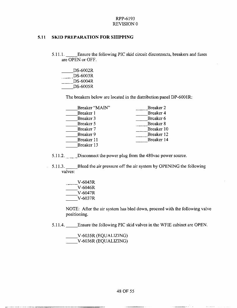
5.11 SKID PREPARATION FOR SHIPPING
5.11.1. - Ensure the following PIC skid circuit disconnects, breakers and fuses are OPEN or OFF.
DS-6002R DS-6003R
-DS-6004R -DS-6005R
The breakers below are located in the distribution panel DP-6001R:
-Breaker “MAIN’ -Breaker 2 Breaker 1 -Breaker 4 Breaker 3 -Breaker 6 Breaker 5 -Breaker 8 Breaker 7 -Breaker 10 Breaker 9 -Breaker 12 Breaker 11 -Breaker 14 Breaker 13
5.11.2.- Disconnect the power plug ffom the 48Ovac power source.
5.11.3.- Bleed the air pressure off the air system by OPENING the following valves:
-V-6043R V-6046R V-6047R V-6037R
NOTE: AAer the air system has bled down, proceed with the following valve positioning.
5.11.4. - Ensure the following PIC skid valves in the WFIE cabinet are OPEN.
-V-6035R (EQUALIZING) V-6036R (EQUALIZING)
RPP-6 193 REVISION 0
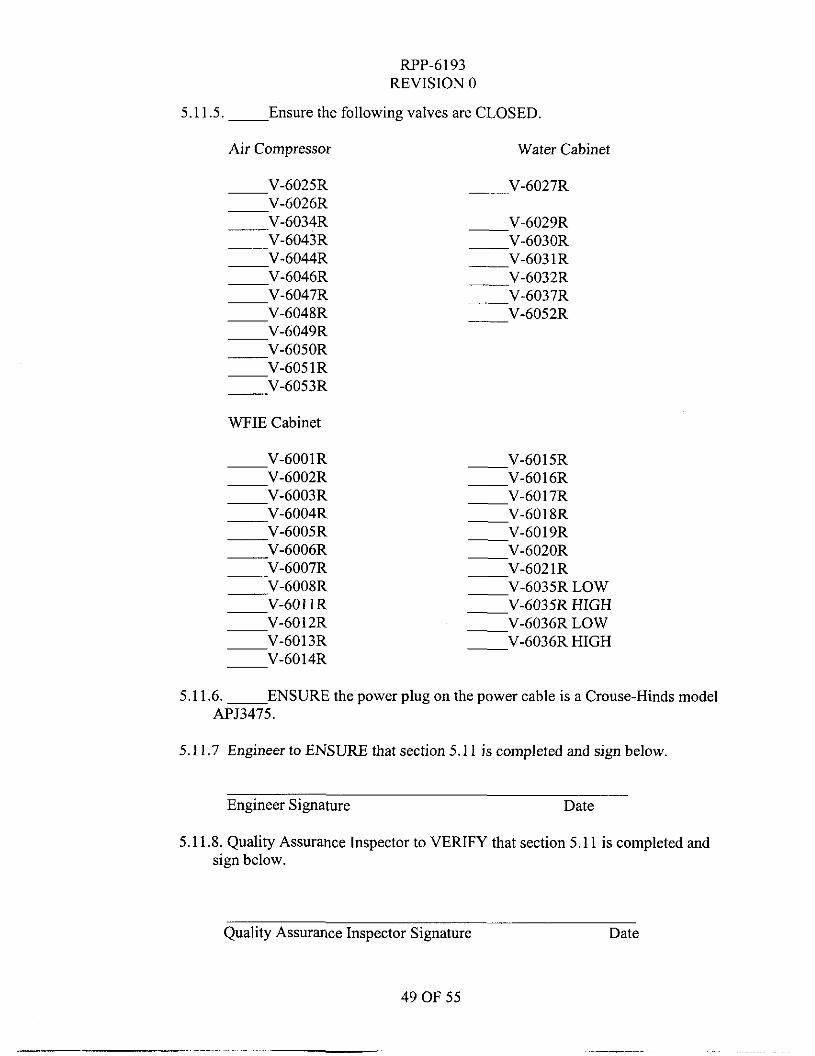
5.11.5.- Ensure the following valves are CLOSED.
Air Compressor Water Cabinet
V-6025R V-6026R
-V-6034R V-6043R V-6044R V-6046R V-6047R V-6048R V-6049R V-6050R V-6051R
-V-6053R
WFIE Cabinet
V-6001R V-6002R
___V-6027R
-V-6029R -V-6030R -V-603 1R
V-6003R -V-6017R V - 6 0 0 4 R -V-6018R V - 6 0 0 5 R -V-6019R V - 6 0 0 6 R -V-6020R V - 6 0 0 7 R -V-6021R -V-6008R -V-6035R LOW
V-6011R -V-6035R HIGH V-6012R -V-6036R LOW V-6013R -V-6036R HIGH V-6014R
5.11.6. - ENSURE the power plug on the power cable is a Crouse-Hinds model APJ3475.
5.11.7 Engineer to ENSURE that section 5.11 is completed and sign below.
Engineer Signature Date
5.1 1.8. Quality Assurance Inspector to VERIFY that section 5.1 1 is completed and sign below.
Quality Assurance Inspector Signature Date
49 OF 55
RPP-6193 REVISION 0
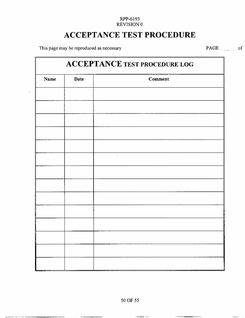
ACCEPTANCE TEST PROCEDURE This page may be reproduced as necessary PAGE - of
SO OF 55
.
RPP-6193 REVISION 0
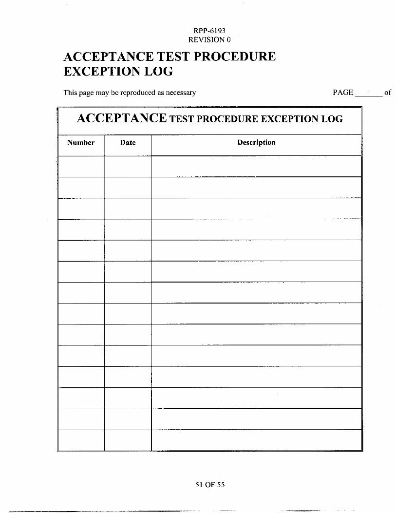
ACCEPTANCE TEST PROCEDURE EXCEPTION LOG This page may be reproduced as necessary PAGE of
ACCEPTANCE TEST PROCEDURE EXCEPTION LOG
51 OF 55
RPP-6193 REVISION 0
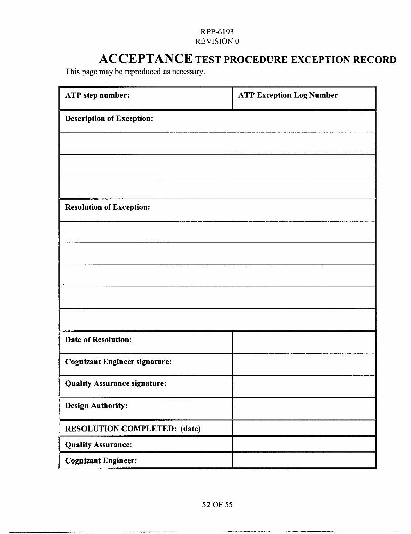
ATP step number:
ACCEPTANCE TEST PROCEDURE EXCEPTION RECORD
ATP Exception Log Number
This page may be reproduced as necessary.
~
Description of Exception:
Resolution of Exception:
Date of Resolution:
Cognizant Engineer signature:
Quality Assurance signature: I Design Authority:
RESOLUTION COMPLETED: (date)
Quality Assurance:
Cognizant Engineer:
52 OF 55
_. ..
RPP-6193 REVISION 0
ACCEPTANCE TEST PROCEDURE ACCEPTANCE RECORD
Section 5.0 of the Acceptance Test Procedure has been completed including completion of all exceptions. The test results are accepted by the undersigned:
Cognizant Engineer (Signature) (Print Name) Date
Quality Assurance (Signature) (Print Name) Date
53 OF 55
-
RPP-6193 REVISION 0
PROCEDURE PERFORMER SIGNATURE SHEET
PRINT NAME SIGNATURE
All personnel who will be performing, initialing and signing the procedure shall enter their printed name, signature and initials below.
INITIALS
RPP-6193 REVISION 0
PRINT NAME
PRE-JOB BRIEF SIGNATURE PAGE
SIGNATURE
55 OF 55