Embed Size (px)
Citation preview
HL-0134-2
ORIENTAL MOTOR CO., LTD.
EZS/EZC Series Controller
DATA SETTING MANUAL
4
� This product must be handled by qualified personnel with expert knowledge of elec-trical and mechanical engineering.
� Should you require the inspection or repair of internal parts, please contact theOriental Motor branch or sales office from which you purchased the product.
� The figures and tables provided in this document are intended to help you under-stand the content of the text. They should not be construed in any way as guar-anteeing the resultant operation.
� Oriental Motor shall not be liable whatsoever for any patent-related problem aris-ing in connection with the use of any information, circuit, equipment or device de-scribed in this document.
� The technical specifications are subject to change without prior notice for the pur-pose of improvement in product performance.
� This document is protected under the applicable copyright laws. No part of thisdocument may be reproduced, stored, changed, duplicated or transmitted digitally(via printing, copying, microfilming or any other manner) without prior written con-sent from Oriental Motor.
� and are trademarks of Oriental Motor Co., Ltd.� Other product names and company names are the trademarks or registered trade-
marks of their respective companies. The products by other manufacturers referredto in this installation manual are mentioned for reference purposes only; their useis not enforced in any way. Oriental Motor shall not be liable whatsoever for theperformance of another manufacturer’s product or any problem arising from the usethereof.
© Copyright ORIENTAL MOTOR CO., LTD. 2002
Notes to the User
EZS/ EZC Series Controller DATA SETTING MANUAL i
Table of Contents
Chapter Overview…………………………………………… 1-1
1.1 Introduction …………………………………………… 1-11.2 Functions of the Teaching Pendant ………………… 1-11.3 Contents of the Manual ……………………………… 1-21.4 Rules of Notation ……………………………………… 1-3
1
Chapter Startup and Operation ………………2-1
2.1 Starting the Teaching Pendant ………………………2-12.1.1 In the Case of One Axis ………………………2-22.1.2 In the Case of Multiple Axes …………………2-22.1.3 Switching Between Languages ………………2-32.1.4 First Screen of Each Mode……………………2-32.1.5 Error Display Screens …………………………2-6
2
Chapter Creating Operation Data and Starting Operation …………… 3-1
3.1 Procedure for Creating Slider Operation Dataand Starting Operation………………………………… 3-2
3.2 Procedure for Creating Cylinder Operation Dataand Starting Operation…………………………………3-11
3
Chapter Creating and Modifying Operation Data……… 4-1
4.1 Operation Data ………………………………………… 4-14.2 Functions Available in the PRG Mode ……………… 4-24.3 Operation Data Creation Screens…………………… 4-24.4 Creating New Operation Data ……………………… 4-34.5 Editing Operation Data ……………………………… 4-6
4.5.1 Editing Existing Data ………………………… 4-64.5.2 Clearing Data…………………………………… 4-74.5.3 Inserting Data ………………………………… 4-84.5.4 Deleting Data…………………………………… 4-9
4.6 Clearing All Operation Data …………………………4-104.7 Remote Teaching ………………………………………4-114.8 Direct Teaching…………………………………………4-134.9 Setting Range of Operation Data ……………………4-154.10Performing Positioning Operation ……………………4-16
4
ii
Chapter Setting and Modifying Parameters ……………… 5-1
5.1 Parameters……………………………………………… 5-15.2 Functions Available in the PAR Mode ……………… 5-15.3 Parameter Setting Screens…………………………… 5-25.4 Setting and Modifying I/O Parameters……………… 5-35.5 Setting and Modifying Motor Parameters…………… 5-65.6 Setting and Modifying Home Parameters ………… 5-85.7 Setting and Modifying Speed Parameters ………… 5-105.8 Setting and Modifying Common Parameters ……… 5-125.9 Initializing All Data …………………………………… 5-15
5
Chapter Monitoring Operation Data …… 6-1
6.1 Monitoring Functions ………………………………… 6-16.2 Monitor Items Available in the EXT Mode ………… 6-26.3 Descriptions of Monitor Screens …………………… 6-4
6
Chapter Manual Operation and I /O Checking ………………………………… 7-1
7.1 Manual Operation……………………………………… 7-17.1.1 Manual Operation……………………………… 7-17.1.2 Positioning Operation ………………………… 7-2
7.2 I/O Checking…………………………………………… 7-37.2.1 I/O Checking Items …………………………… 7-4
7
Chapter Troubleshooting…………………………… 8-1
8.1 Error Messages………………………………………… 8-18.2 Checking the Alarm History ………………………… 8-3
8
EZS/ EZC Series Controller DATA SETTING MANUAL iii
Appendix Table of Operation Switching…A-1
A.1 External (EXT) Mode Operation Monitor <Controller Mode> (English display) …………………A-1
A.2 Program (PRG) Mode Operation Data Setting <Controller Mode> (English display) …………………A-2
A.3.1 Parameter (PAR) Mode 1 Parameter Setting <Controller Mode> (English display) ………………A-3
A.3.2 Parameter (PAR) Mode 2 Parameter Setting <Controller Mode> (English display) ………………A-4
A.4 Test (TST) Mode Manual Drive and I/O Checking <Controller mode> (English display) …………………A-5
A.5 External (EXT) Mode Operation Monitor <Driver Mode> (English display)………………………A-6
A.6 Parameter (PAR) Mode 1 Parameter Setting <Driver Mode> (English display)………………………A-7
A.7 Test (TST) Mode I/O Checking <Driver Mode> (English display)………………………A-8
A.8 External (EXT) Mode Operation Monitor <Controller Mode> (Japanese display) ………………A-9
A.9 Program (PRG) Mode Operation Data Setting <Controller Mode> (Japanese display) ………………A-10
A.10.1 Parameter (PAR) Mode 1 Parameter Setting <Controller Mode> (Japanese display)……………A-11
A.10.2 Parameter (PAR) Mode 2 Parameter Setting <Controller Mode> (Japanese display)……………A-12
A.11 Test (TST) Mode Manual Drive and I/O Checking <Controller mode> (Japanese display) ……………A-13
A.12 External (EXT) Mode Operation Monitor <Driver Mode> (Japanese display) …………………A-14
A.13 Parameter (PAR) Mode 1 Parameter Setting <Driver Mode> (Japanese display) …………………A-15
A.14 Test (TST) Mode I/O Checking <Driver Mode> (Japanese display) …………………A-16
A

iv
EZS/ EZC Series Controller DATA SETTING MANUAL 1-1
Chapter 1 Overview
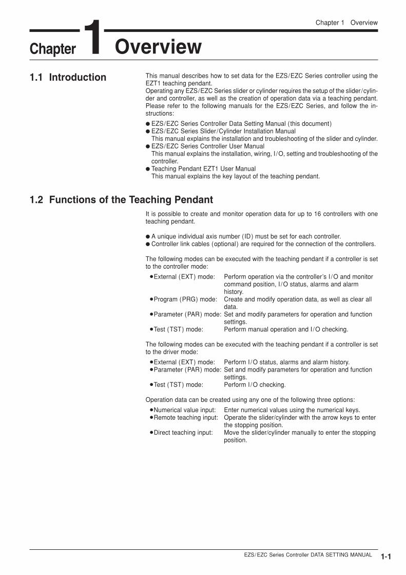
This manual describes how to set data for the EZS/EZC Series controller using theEZT1 teaching pendant.Operating any EZS/EZC Series slider or cylinder requires the setup of the slider/cylin-der and controller, as well as the creation of operation data via a teaching pendant.Please refer to the following manuals for the EZS/EZC Series, and follow the in-structions:
� EZS/EZC Series Controller Data Setting Manual (this document)� EZS/EZC Series Slider/Cylinder Installation Manual
This manual explains the installation and troubleshooting of the slider and cylinder.� EZS/EZC Series Controller User Manual
This manual explains the installation, wiring, I /O, setting and troubleshooting of thecontroller.
� Teaching Pendant EZT1 User ManualThis manual explains the key layout of the teaching pendant.
It is possible to create and monitor operation data for up to 16 controllers with oneteaching pendant.
� A unique individual axis number (ID) must be set for each controller.� Controller link cables (optional) are required for the connection of the controllers.
The following modes can be executed with the teaching pendant if a controller is setto the controller mode:
�External (EXT) mode: Perform operation via the controller’s I /O and monitor command position, I /O status, alarms and alarmhistory.
�Program (PRG) mode: Create and modify operation data, as well as clear alldata.
�Parameter (PAR) mode: Set and modify parameters for operation and function settings.
�Test (TST) mode: Perform manual operation and I /O checking.
The following modes can be executed with the teaching pendant if a controller is setto the driver mode:
�External (EXT) mode: Perform I /O status, alarms and alarm history.�Parameter (PAR) mode: Set and modify parameters for operation and function
settings.�Test (TST) mode: Perform I /O checking.
Operation data can be created using any one of the following three options:�Numerical value input: Enter numerical values using the numerical keys.�Remote teaching input: Operate the slider/cylinder with the arrow keys to enter
the stopping position.� Direct teaching input: Move the slider/cylinder manually to enter the stopping
position.
Chapter 11.1 Introduction
1.2 Functions of the Teaching Pendant
Overview
1-2
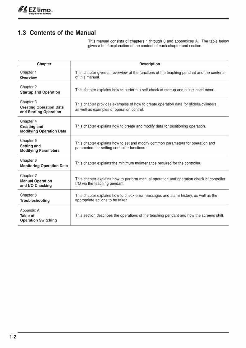
1.3 Contents of the ManualThis manual consists of chapters 1 through 8 and appendixes A. The table belowgives a brief explanation of the content of each chapter and section.
Chapter
Chapter 1Overview
Description
This chapter gives an overview of the functions of the teaching pendant and the contentsof this manual.
Chapter 3 Creating Operation Data and Starting Operation
This chapter provides examples of how to create operation data for sliders/cylinders, as well as examples of operation control.
Chapter 2 Startup and Operation
This chapter explains how to perform a self-check at startup and select each menu.
Chapter 4 Creating and Modifying Operation Data
This chapter explains how to create and modify data for positioning operation.
Chapter 5 Setting and Modifying Parameters
This chapter explains how to set and modify common parameters for operation and parameters for setting controller functions.
Chapter 6 Monitoring Operation Data
This chapter explains the minimum maintenance required for the controller.
Chapter 7Manual Operation and I/O Checking
This chapter explains how to perform manual operation and operation check of controllerI/O via the teaching pendant.
Chapter 8Troubleshooting
This chapter explains how to check error messages and alarm history, as well as the appropriate actions to be taken.
Appendix ATable of Operation Switching
This section describes the operations of the teaching pendant and how the screens shift.
EZS/ EZC Series Controller DATA SETTING MANUAL 1-3
Chapter 1 Overview
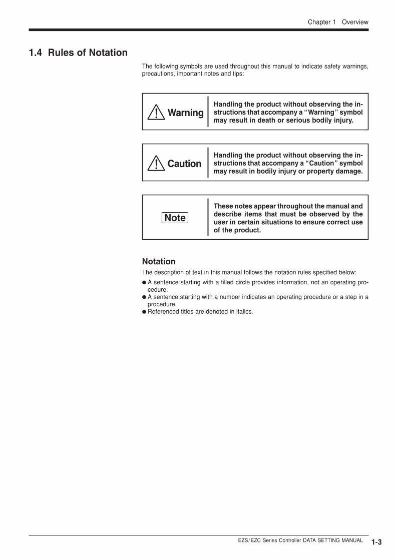
1.4 Rules of NotationThe following symbols are used throughout this manual to indicate safety warnings,precautions, important notes and tips:
WarningHandling the product without observing the in-structions that accompany a “Warning” symbolmay result in death or serious bodily injury.
CautionHandling the product without observing the in-structions that accompany a “Caution” symbolmay result in bodily injury or property damage.
These notes appear throughout the manual anddescribe items that must be observed by theuser in certain situations to ensure correct useof the product.
NotationThe description of text in this manual follows the notation rules specified below:
� A sentence starting with a filled circle provides information, not an operating pro-cedure.
� A sentence starting with a number indicates an operating procedure or a step in aprocedure.
� Referenced titles are denoted in italics.
Note

1-4
EZS/ EZC Series Controller DATA SETTING MANUAL 2-1
Chapter 2 Startup and Operation
This chapter describes the representative screens of the teaching pendant displayedin the controller mode, as well as the basic key operations using those screens.
Chapter 2 Startup and Operation
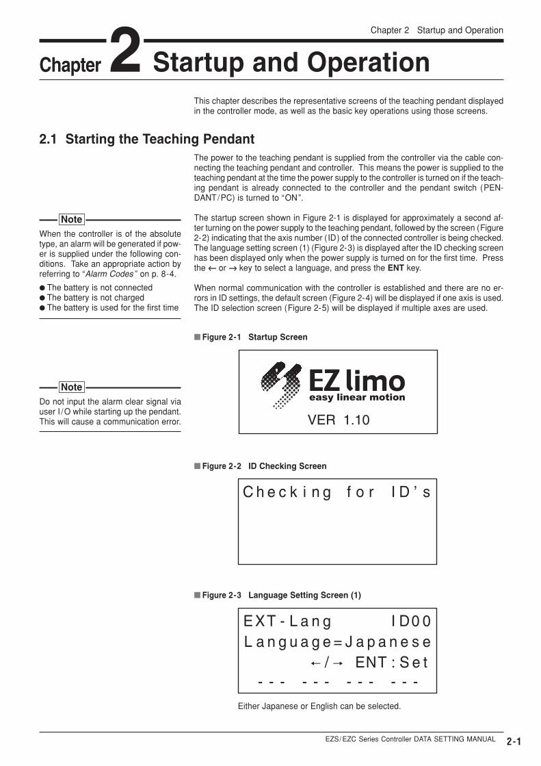
� Figure 2-1 Startup Screen
� Figure 2-2 ID Checking Screen
� Figure 2-3 Language Setting Screen (1)
2.1 Starting the Teaching PendantThe power to the teaching pendant is supplied from the controller via the cable con-necting the teaching pendant and controller. This means the power is supplied to theteaching pendant at the time the power supply to the controller is turned on if the teach-ing pendant is already connected to the controller and the pendant switch (PEN-DANT/PC) is turned to “ON”.
The startup screen shown in Figure 2-1 is displayed for approximately a second af-ter turning on the power supply to the teaching pendant, followed by the screen (Figure2-2) indicating that the axis number (ID) of the connected controller is being checked.The language setting screen (1) (Figure 2-3) is displayed after the ID checking screenhas been displayed only when the power supply is turned on for the first time. Pressthe ←← or →→ key to select a language, and press the ENT key.
When normal communication with the controller is established and there are no er-rors in ID settings, the default screen (Figure 2-4) will be displayed if one axis is used.The ID selection screen (Figure 2-5) will be displayed if multiple axes are used.
When the controller is of the absolutetype, an alarm will be generated if pow-er is supplied under the following con-ditions. Take an appropriate action byreferring to “Alarm Codes ” on p. 8-4.
� The battery is not connected� The battery is not charged� The battery is used for the first time
Note
Do not input the alarm clear signal viauser I /O while starting up the pendant.This will cause a communication error.
Note
Either Japanese or English can be selected.
2-2
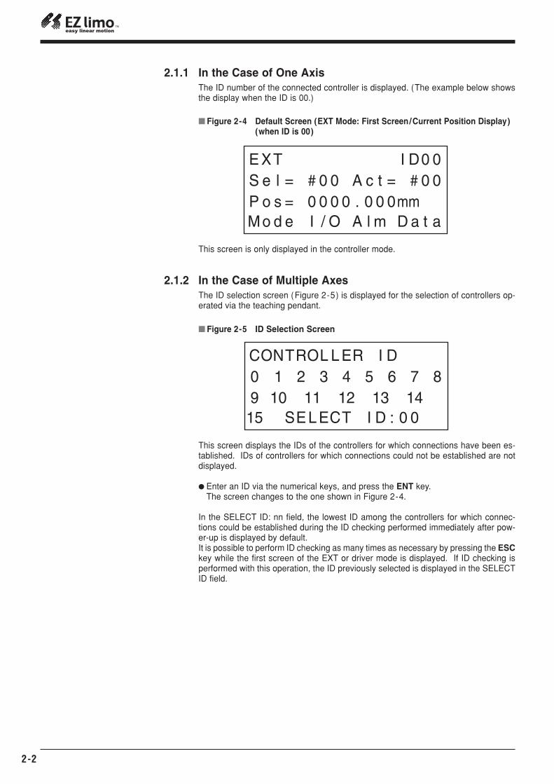
This screen is only displayed in the controller mode.
� Figure 2-4 Default Screen (EXT Mode: First Screen/Current Position Display)(when ID is 00)
2.1.1 In the Case of One AxisThe ID number of the connected controller is displayed. (The example below showsthe display when the ID is 00.)
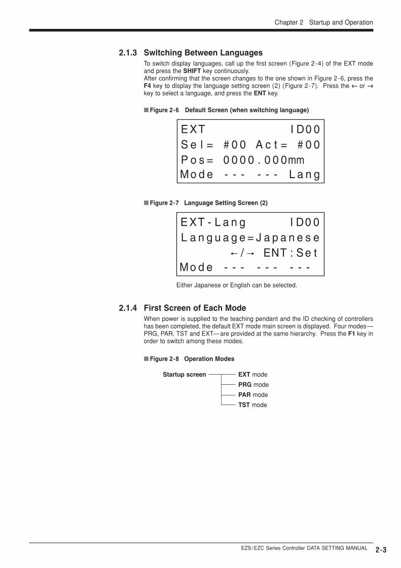
This screen displays the IDs of the controllers for which connections have been es-tablished. IDs of controllers for which connections could not be established are notdisplayed.
� Enter an ID via the numerical keys, and press the ENT key.The screen changes to the one shown in Figure 2-4.
In the SELECT ID: nn field, the lowest ID among the controllers for which connec-tions could be established during the ID checking performed immediately after pow-er-up is displayed by default.It is possible to perform ID checking as many times as necessary by pressing the ESCkey while the first screen of the EXT or driver mode is displayed. If ID checking isperformed with this operation, the ID previously selected is displayed in the SELECTID field.
� Figure 2-5 ID Selection Screen
2.1.2 In the Case of Multiple AxesThe ID selection screen (Figure 2-5) is displayed for the selection of controllers op-erated via the teaching pendant.
EZS/ EZC Series Controller DATA SETTING MANUAL 2-3
Chapter 2 Startup and Operation
Startup screen EXT mode
PRG mode
PAR mode
TST mode
2.1.4 First Screen of Each ModeWhen power is supplied to the teaching pendant and the ID checking of controllershas been completed, the default EXT mode main screen is displayed. Four modes—PRG, PAR, TST and EXT—are provided at the same hierarchy. Press the F1 key inorder to switch among these modes.
� Figure 2-8 Operation Modes
2.1.3 Switching Between LanguagesTo switch display languages, call up the first screen (Figure 2-4) of the EXT modeand press the SHIFT key continuously.After confirming that the screen changes to the one shown in Figure 2-6, press theF4 key to display the language setting screen (2) (Figure 2-7). Press the ←← or →→key to select a language, and press the ENT key.
� Figure 2-6 Default Screen (when switching language)
� Figure 2-7 Language Setting Screen (2)
Either Japanese or English can be selected.
2-4
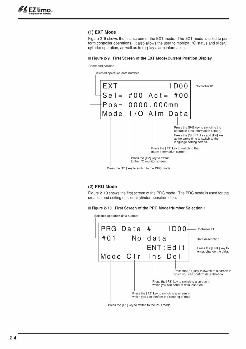
(1) EXT ModeFigure 2-9 shows the first screen of the EXT mode. The EXT mode is used to per-form controller operations. It also allows the user to monitor I /O status and slider /cylinder operation, as well as to display alarm information.
� Figure 2-9 First Screen of the EXT Mode/Current Position Display
(2) PRG ModeFigure 2-10 shows the first screen of the PRG mode. The PRG mode is used for thecreation and editing of slider/cylinder operation data.
Controller ID
Selected operation data number
Command position
Press the [F1] key to switch to the PRG mode.
Press the [F2] key to switch to the I /O monitor screen.
Press the [F3] key to switch to the alarm information screen.
Press the [F4] key to switch to the operation data information screen.
Press the [SHIFT] key and [F4] key at the same time to switch to the language setting screen.
� Figure 2-10 First Screen of the PRG Mode/Number Selection 1
Press the [ENT] key to enter/change the data.
Press the [F1] key to switch to the PAR mode.
Press the [F2] key to switch to a screen in which you can confirm the clearing of data.
Press the [F3] key to switch to a screen in which you can confirm data insertion.
Press the [F4] key to switch to a screen in which you can confirm data deletion.
Data description
Controller ID
Selected operation data number
EZS/ EZC Series Controller DATA SETTING MANUAL 2-5
Chapter 2 Startup and Operation
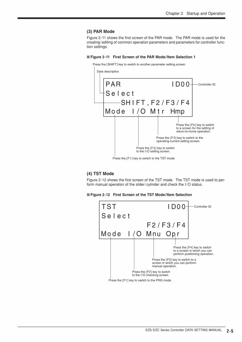
(3) PAR ModeFigure 2-11 shows the first screen of the PAR mode. The PAR mode is used for thecreating /editing of common operation parameters and parameters for controller func-tion settings.
(4) TST ModeFigure 2-12 shows the first screen of the TST mode. The TST mode is used to per-form manual operation of the slider /cylinder and check the I /O status.
� Figure 2-11 First Screen of the PAR Mode/ Item Selection 1
Controller ID
Data description
Press the [F1] key to switch to the TST mode.
Press the [F2] key to switch to the I /O setting screen.
Press the [F3] key to switch to the operating-current setting screen.
Press the [F4] key to switch to a screen for the setting of return-to-home operation.
Press the [SHIFT] key to switch to another parameter setting screen.
� Figure 2-12 First Screen of the TST Mode/ Item Selection
Press the [F1] key to switch to the PRG mode.
Press the [F2] key to switch to the I /O checking screen.
Press the [F3] key to switch to a screen in which you can perform manual operation.
Press the [F4] key to switch to a screen in which you can perform positioning operation.
Controller ID
2-6
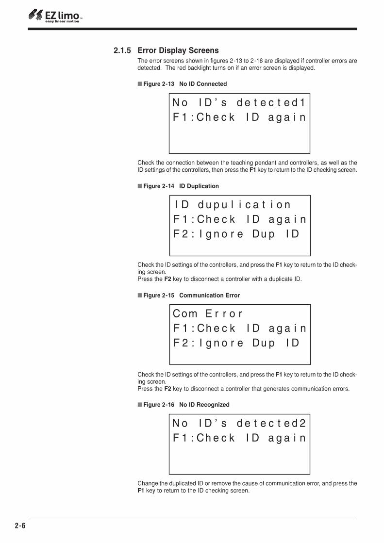
2.1.5 Error Display ScreensThe error screens shown in figures 2-13 to 2-16 are displayed if controller errors aredetected. The red backlight turns on if an error screen is displayed.
Check the connection between the teaching pendant and controllers, as well as theID settings of the controllers, then press the F1 key to return to the ID checking screen.
Check the ID settings of the controllers, and press the F1 key to return to the ID check-ing screen.Press the F2 key to disconnect a controller with a duplicate ID.
� Figure 2-13 No ID Connected
� Figure 2-14 ID Duplication
Check the ID settings of the controllers, and press the F1 key to return to the ID check-ing screen.Press the F2 key to disconnect a controller that generates communication errors.
� Figure 2-15 Communication Error
Change the duplicated ID or remove the cause of communication error, and press theF1 key to return to the ID checking screen.
� Figure 2-16 No ID Recognized
EZS/ EZC Series Controller DATA SETTING MANUAL 3-1
In this chapter the following operations are described in the sequence.Note that the explanation here assumes that the installation and wiring of the slider,controller and power supply are complete.It is also assumed that the controller has been started in the controller mode, and thattwo or more controllers are not connected via a daisy chain using controller link ca-bles.Please refer to Chapter 2, “ Startup and Operation ”, to fully understand the functionsof the display screens on the teaching pendant.
� Turning on the power supply� Checking slider operations� Creating operation data� Setting parameters� Performing the positioning operation
For the purpose of the explanations provided in this chapter, the minimum numericalvalues and conditions are set for operation data and parameters. Default values areused for the data displayed in screen images.For convenience, data values shown in this manual include both metric and (imperi-al) units.However, the EZT1 Teaching Pendant only displays metric units.Operation data and parameters are saved even after the power supply to the con-troller is turned off. Refer to the procedure explained below for the editing of opera-tion data and parameters.
Chapter 3 Creating Operation Data and Starting Operation
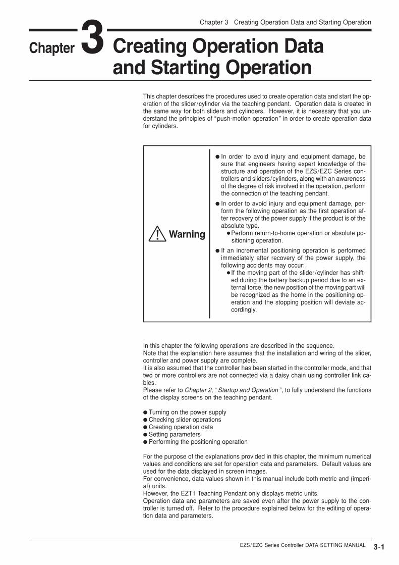
This chapter describes the procedures used to create operation data and start the op-eration of the slider/cylinder via the teaching pendant. Operation data is created inthe same way for both sliders and cylinders. However, it is necessary that you un-derstand the principles of “push-motion operation” in order to create operation datafor cylinders.
Chapter 3 Creating Operation Data and Starting Operation
Warning
� In order to avoid injury and equipment damage, besure that engineers having expert knowledge of thestructure and operation of the EZS/EZC Series con-trollers and sliders/cylinders, along with an awarenessof the degree of risk involved in the operation, performthe connection of the teaching pendant.
� In order to avoid injury and equipment damage, per-form the following operation as the first operation af-ter recovery of the power supply if the product is of theabsolute type.
� Perform return-to-home operation or absolute po-sitioning operation.
� If an incremental positioning operation is performedimmediately after recovery of the power supply, thefollowing accidents may occur:
� If the moving part of the slider/cylinder has shift-ed during the battery backup period due to an ex-ternal force, the new position of the moving part willbe recognized as the home in the positioning op-eration and the stopping position will deviate ac-cordingly.
Screen display
3-2
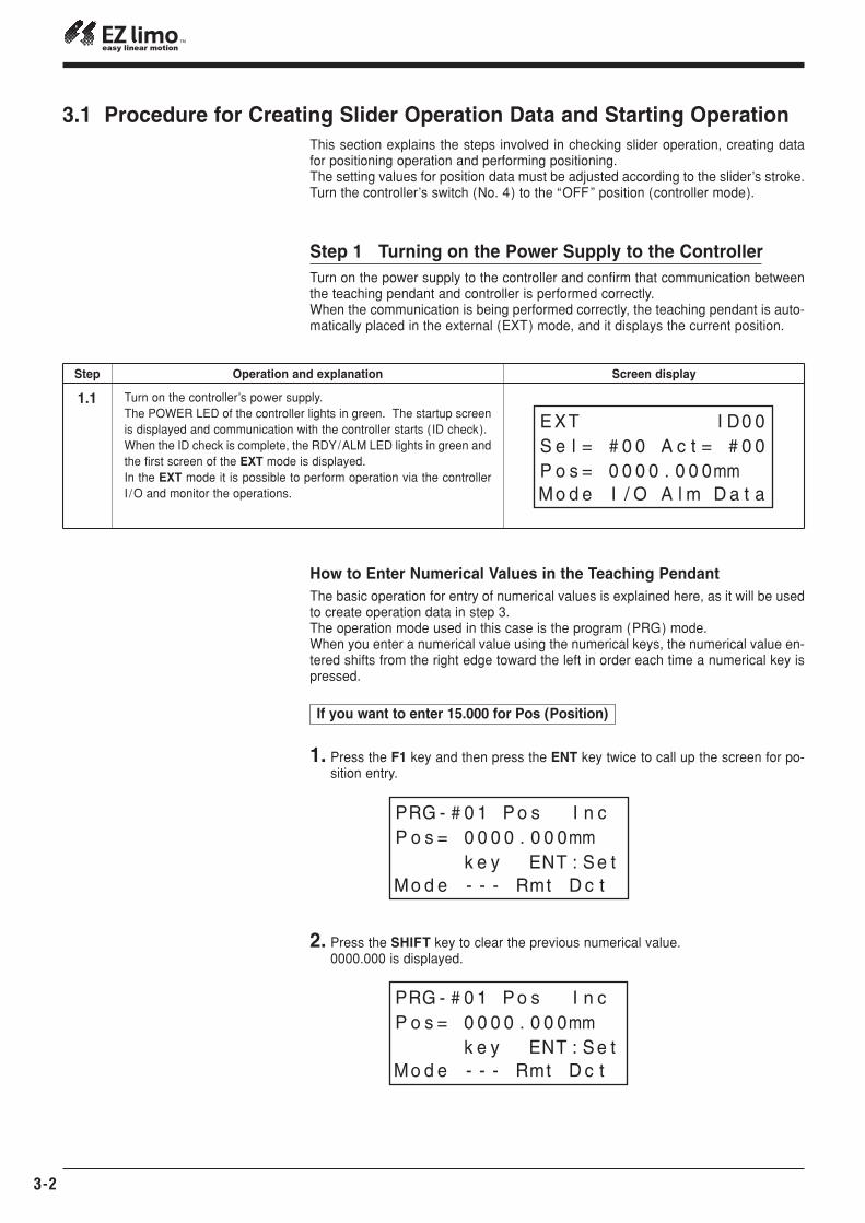
Step 1 Turning on the Power Supply to the ControllerTurn on the power supply to the controller and confirm that communication betweenthe teaching pendant and controller is performed correctly.When the communication is being performed correctly, the teaching pendant is auto-matically placed in the external (EXT) mode, and it displays the current position.
How to Enter Numerical Values in the Teaching PendantThe basic operation for entry of numerical values is explained here, as it will be usedto create operation data in step 3.The operation mode used in this case is the program (PRG) mode.When you enter a numerical value using the numerical keys, the numerical value en-tered shifts from the right edge toward the left in order each time a numerical key ispressed.
Step Operation and explanation
1.1 Turn on the controller’s power supply.The POWER LED of the controller lights in green. The startup screenis displayed and communication with the controller starts (ID check).When the ID check is complete, the RDY/ALM LED lights in green andthe first screen of the EXT mode is displayed.In the EXT mode it is possible to perform operation via the controllerI /O and monitor the operations.
If you want to enter 15.000 for Pos (Position)
1. Press the F1 key and then press the ENT key twice to call up the screen for po-sition entry.
2. Press the SHIFT key to clear the previous numerical value.0000.000 is displayed.
3.1 Procedure for Creating Slider Operation Data and Starting OperationThis section explains the steps involved in checking slider operation, creating datafor positioning operation and performing positioning.The setting values for position data must be adjusted according to the slider’s stroke.Turn the controller’s switch (No. 4) to the “OFF” position (controller mode).
EZS/ EZC Series Controller DATA SETTING MANUAL
Chapter 3 Creating Operation Data and Starting Operation
3-3
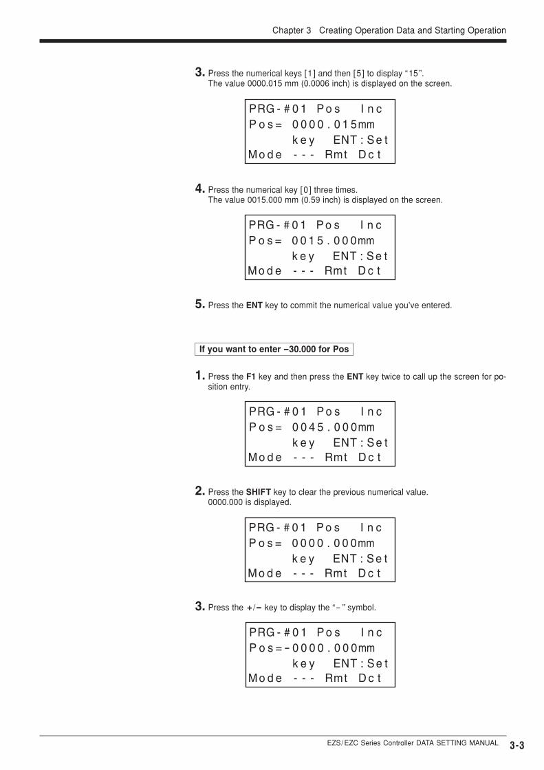
3. Press the numerical keys [1 ] and then [5 ] to display “15”. The value 0000.015 mm (0.0006 inch) is displayed on the screen.
4. Press the numerical key [0 ] three times.The value 0015.000 mm (0.59 inch) is displayed on the screen.
5. Press the ENT key to commit the numerical value you’ve entered.
If you want to enter -30.000 for Pos
1. Press the F1 key and then press the ENT key twice to call up the screen for po-sition entry.
2. Press the SHIFT key to clear the previous numerical value.0000.000 is displayed.
3. Press the + /- key to display the “- ” symbol.
3-4
2.1
2.2
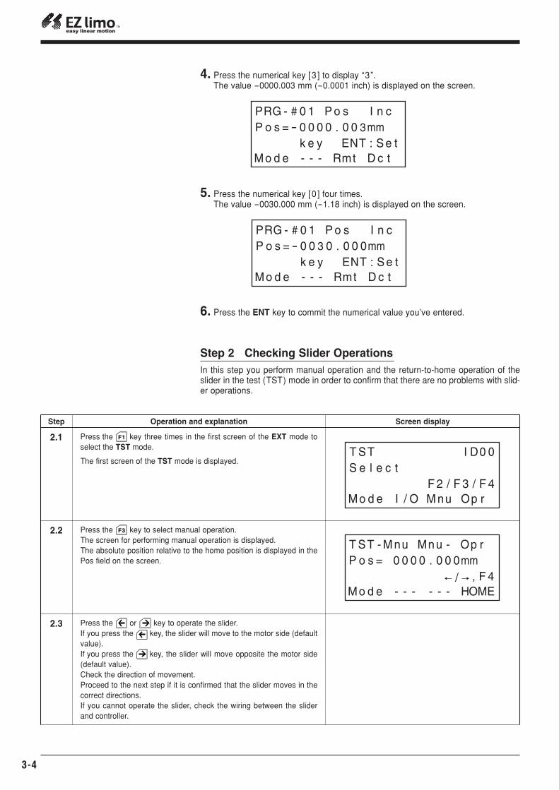
Press the key three times in the first screen of the EXT mode toselect the TST mode.
The first screen of the TST mode is displayed.
Press the key to select manual operation.The screen for performing manual operation is displayed.The absolute position relative to the home position is displayed in thePos field on the screen.
2.3 Press the or key to operate the slider.If you press the key, the slider will move to the motor side (defaultvalue).If you press the key, the slider will move opposite the motor side(default value).Check the direction of movement.Proceed to the next step if it is confirmed that the slider moves in thecorrect directions.If you cannot operate the slider, check the wiring between the sliderand controller.
F1
F3
4. Press the numerical key [3 ] to display “3”.The value -0000.003 mm (-0.0001 inch) is displayed on the screen.
5. Press the numerical key [0 ] four times.The value -0030.000 mm (-1.18 inch) is displayed on the screen.
6. Press the ENT key to commit the numerical value you’ve entered.
Screen display
Step 2 Checking Slider OperationsIn this step you perform manual operation and the return-to-home operation of theslider in the test (TST) mode in order to confirm that there are no problems with slid-er operations.
Step Operation and explanation
EZS/ EZC Series Controller DATA SETTING MANUAL
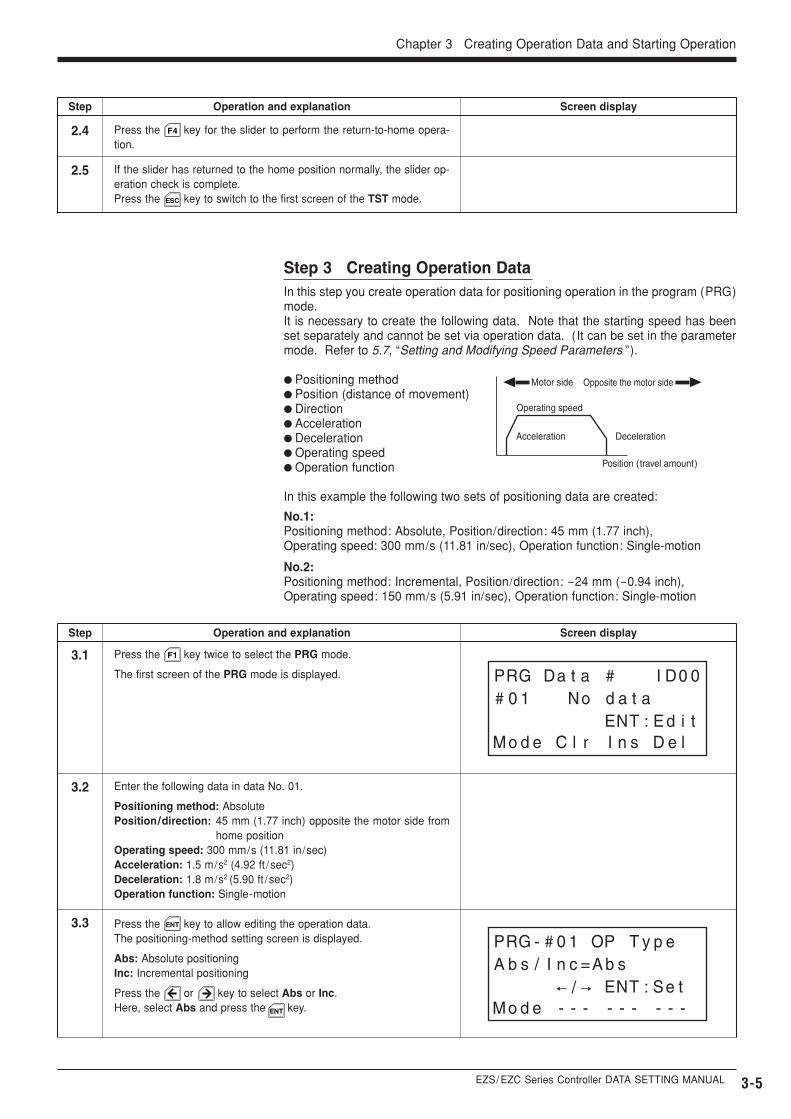
Step 3 Creating Operation DataIn this step you create operation data for positioning operation in the program (PRG)mode.It is necessary to create the following data. Note that the starting speed has beenset separately and cannot be set via operation data. (It can be set in the parametermode. Refer to 5.7, “Setting and Modifying Speed Parameters ”).
� Positioning method� Position (distance of movement)� Direction� Acceleration� Deceleration� Operating speed� Operation function
In this example the following two sets of positioning data are created:
No.1:Positioning method: Absolute, Position/direction: 45 mm (1.77 inch), Operating speed: 300 mm/s (11.81 in/sec), Operation function: Single-motion
No.2:Positioning method: Incremental, Position/direction: -24 mm (-0.94 inch), Operating speed: 150 mm/s (5.91 in/sec), Operation function: Single-motion
Chapter 3 Creating Operation Data and Starting Operation
3-5
2.4 Press the key for the slider to perform the return-to-home opera-tion.
2.5 If the slider has returned to the home position normally, the slider op-eration check is complete.Press the key to switch to the first screen of the TST mode.
3.1
3.2
Press the key twice to select the PRG mode.
The first screen of the PRG mode is displayed.
Enter the following data in data No. 01.
Positioning method: AbsolutePosition/direction: 45 mm (1.77 inch) opposite the motor side from
home positionOperating speed: 300 mm/s (11.81 in/sec)Acceleration: 1.5 m/s2 (4.92 ft /sec2)Deceleration: 1.8 m/s2 (5.90 ft /sec2)Operation function: Single-motion
3.3 Press the key to allow editing the operation data.The positioning-method setting screen is displayed.
Abs: Absolute positioningInc: Incremental positioning
Press the or key to select Abs or Inc.Here, select Abs and press the key.
F4
F1
ENT
ESC
ENT
Operating speed
Motor side Opposite the motor side
Acceleration Deceleration
Position (travel amount)
Screen displayStep Operation and explanation
Screen displayStep Operation and explanation
3-6
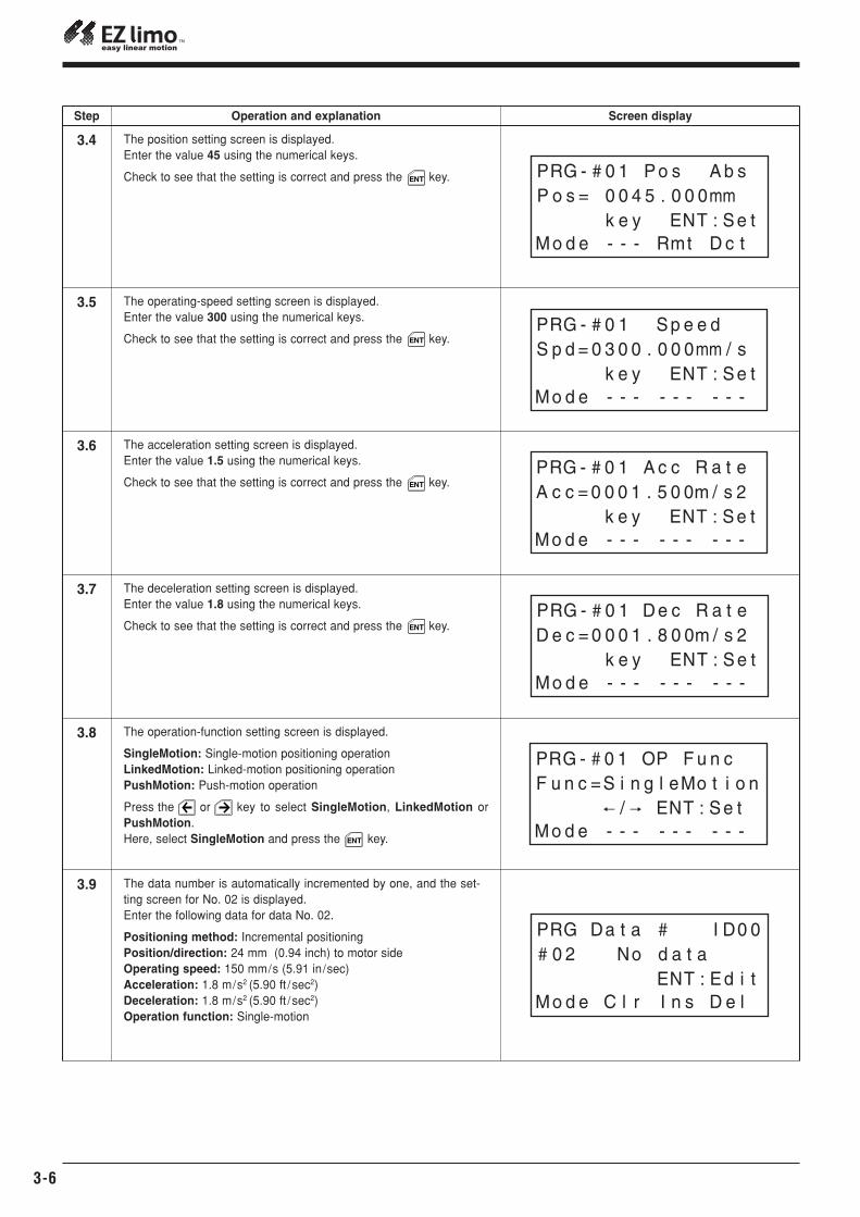
3.4
3.5
The position setting screen is displayed.Enter the value 45 using the numerical keys.
Check to see that the setting is correct and press the key.
The operating-speed setting screen is displayed.Enter the value 300 using the numerical keys.
Check to see that the setting is correct and press the key.
3.6 The acceleration setting screen is displayed.Enter the value 1.5 using the numerical keys.
Check to see that the setting is correct and press the key.
3.7 The deceleration setting screen is displayed.Enter the value 1.8 using the numerical keys.
Check to see that the setting is correct and press the key.
3.8 The operation-function setting screen is displayed.
SingleMotion: Single-motion positioning operationLinkedMotion: Linked-motion positioning operationPushMotion: Push-motion operation
Press the or key to select SingleMotion, LinkedMotion orPushMotion.Here, select SingleMotion and press the key.
3.9 The data number is automatically incremented by one, and the set-ting screen for No. 02 is displayed.Enter the following data for data No. 02.
Positioning method: Incremental positioningPosition/direction: 24 mm (0.94 inch) to motor sideOperating speed: 150 mm/s (5.91 in/sec)Acceleration: 1.8 m/s2 (5.90 ft /sec2)Deceleration: 1.8 m/s2 (5.90 ft /sec2)Operation function: Single-motion
ENT
ENT
ENT
ENT
ENT
Screen displayStep Operation and explanation
EZS/ EZC Series Controller DATA SETTING MANUAL 3-7
Chapter 3 Creating Operation Data and Starting Operation
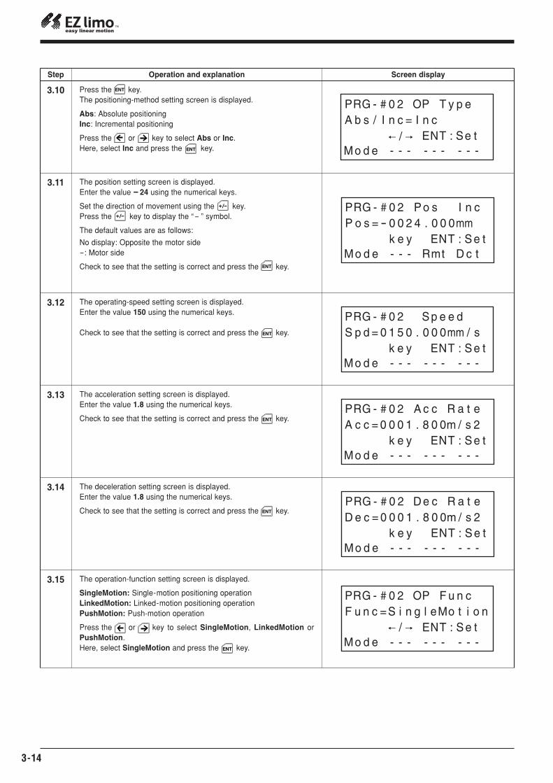
3.10
3.11
3.12
3.13
3.14
3.15
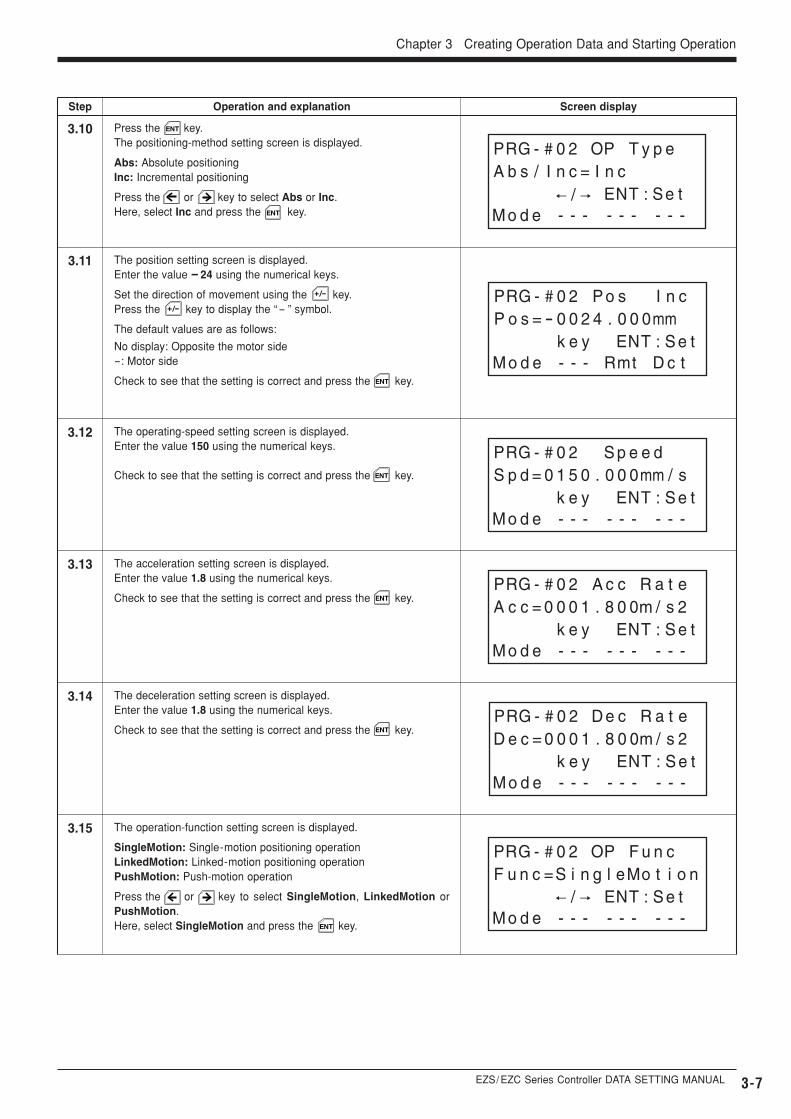
The position setting screen is displayed.Enter the value -24 using the numerical keys.
Set the direction of movement using the key.Press the key to display the “- ” symbol.
The default values are as follows:
No display: Opposite the motor side-: Motor side
Check to see that the setting is correct and press the key.
+/-
+/-
ENT
The operating-speed setting screen is displayed.Enter the value 150 using the numerical keys.
Check to see that the setting is correct and press the key.ENT
The acceleration setting screen is displayed.Enter the value 1.8 using the numerical keys.
Check to see that the setting is correct and press the key.ENT
The deceleration setting screen is displayed.Enter the value 1.8 using the numerical keys.
Check to see that the setting is correct and press the key.ENT
The operation-function setting screen is displayed.
SingleMotion: Single-motion positioning operationLinkedMotion: Linked-motion positioning operationPushMotion: Push-motion operation
Press the or key to select SingleMotion, LinkedMotion orPushMotion.Here, select SingleMotion and press the key.ENT
Screen displayStep Operation and explanation
Press the key.The positioning-method setting screen is displayed.
Abs: Absolute positioningInc: Incremental positioning
Press the or key to select Abs or Inc.Here, select Inc and press the key.
ENT
ENT
3-8
3.16
3.17
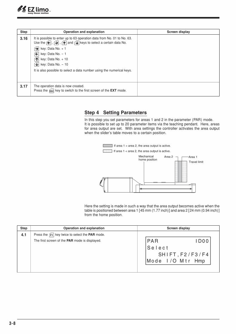
It is possible to enter up to 63 operation data from No. 01 to No. 63.Use the , , and keys to select a certain data No.
key: Data No. + 1
key: Data No. - 1
key: Data No. + 10
key: Data No. - 10
It is also possible to select a data number using the numerical keys.
The operation data is now created.Press the key to switch to the first screen of the EXT mode.ESC
Here the setting is made in such a way that the area output becomes active when thetable is positioned between area 1 [45 mm (1.77 inch)] and area 2 [24 mm (0.94 inch) ]from the home position.
4.1 Press the key twice to select the PAR mode.
The first screen of the PAR mode is displayed.
F1
Area 1Area 2Mechanical home position
Travel limit
If area 1 > area 2, the area output is active.
If area 1 < area 2, the area output is active.
Screen displayStep Operation and explanation
Step 4 Setting ParametersIn this step you set parameters for areas 1 and 2 in the parameter (PAR) mode.It is possible to set up to 20 parameter items via the teaching pendant. Here, areasfor area output are set. With area settings the controller activates the area outputwhen the slider’s table moves to a certain position.
Screen displayStep Operation and explanation
EZS/ EZC Series Controller DATA SETTING MANUAL 3-9
Chapter 3 Creating Operation Data and Starting Operation
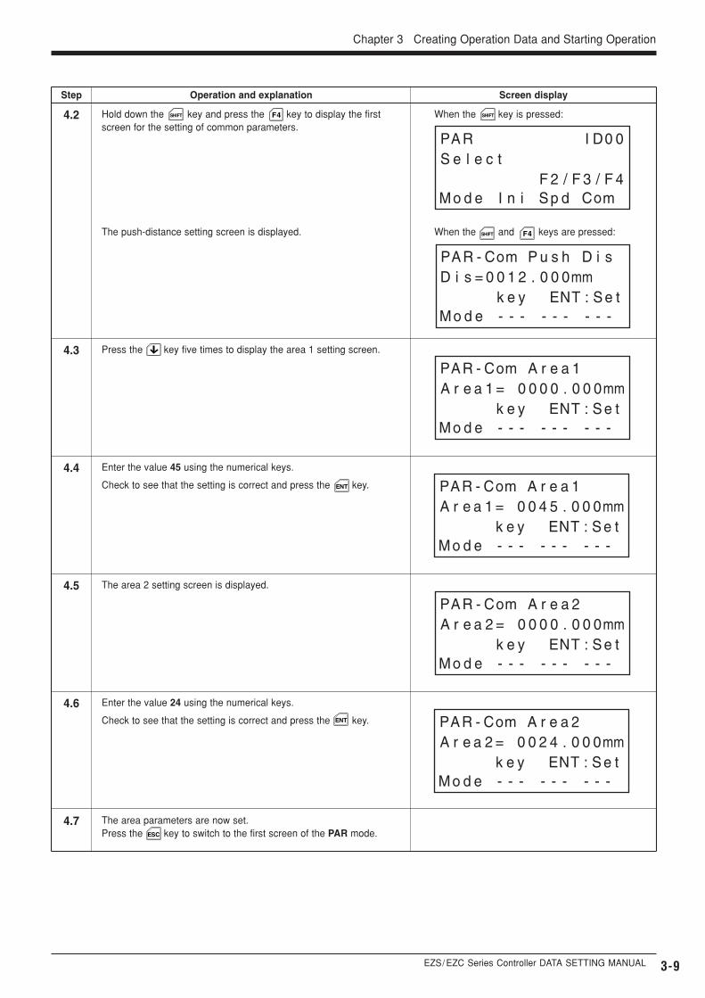
Press the key five times to display the area 1 setting screen.4.3
4.4 Enter the value 45 using the numerical keys.
Check to see that the setting is correct and press the key.ENT
When the and keys are pressed:
4.2 Hold down the key and press the key to display the firstscreen for the setting of common parameters.
SHIFT SHIFT
SHIFT F4
F4
The push-distance setting screen is displayed.
When the key is pressed:
4.5 The area 2 setting screen is displayed.
4.6 Enter the value 24 using the numerical keys.
Check to see that the setting is correct and press the key.
4.7
ENT
The area parameters are now set.Press the key to switch to the first screen of the PAR mode.ESC
Screen displayStep Operation and explanation
3-10
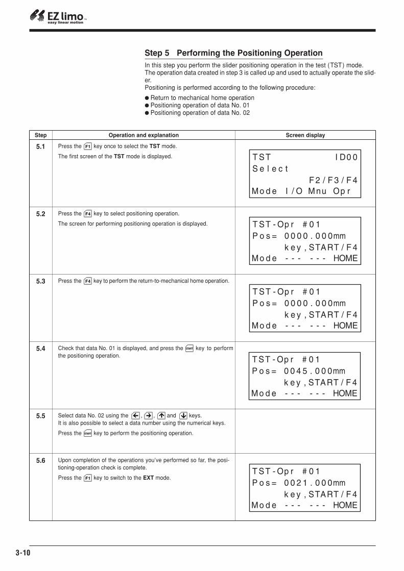
5.1
5.2
Press the key once to select the TST mode.
The first screen of the TST mode is displayed.
Press the key to select positioning operation.
The screen for performing positioning operation is displayed.
Press the key to perform the return-to-mechanical home operation.5.3
F1
F4
F4
Check that data No. 01 is displayed, and press the key to performthe positioning operation.
5.4 START
Select data No. 02 using the , , and keys.It is also possible to select a data number using the numerical keys.
Press the key to perform the positioning operation.
5.5
Upon completion of the operations you’ve performed so far, the posi-tioning-operation check is complete.
Press the key to switch to the EXT mode.
5.6
START
F1
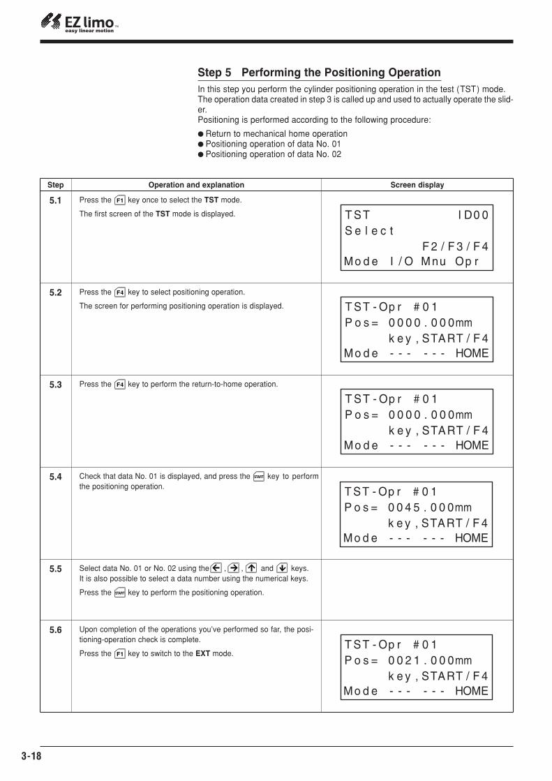
Step 5 Performing the Positioning OperationIn this step you perform the slider positioning operation in the test (TST) mode.The operation data created in step 3 is called up and used to actually operate the slid-er.Positioning is performed according to the following procedure:
� Return to mechanical home operation� Positioning operation of data No. 01� Positioning operation of data No. 02
Screen displayStep Operation and explanation
EZS/ EZC Series Controller DATA SETTING MANUAL
Chapter 3 Creating Operation Data and Starting Operation
3-11
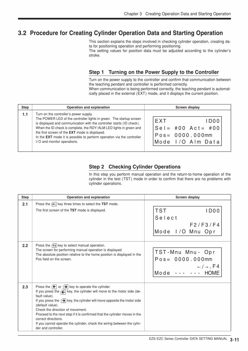
2.1
2.2
Press the key three times to select the TST mode.
The first screen of the TST mode is displayed.
Press the key to select manual operation.The screen for performing manual operation is displayed.The absolute position relative to the home position is displayed in thePos field on the screen.
2.3 Press the or key to operate the cylinder.If you press the key, the cylinder will move to the motor side (de-fault value).If you press the key, the cylinder will move opposite the motor side(default value).Check the direction of movement.Proceed to the next step if it is confirmed that the cylinder moves in thecorrect directions.If you cannot operate the cylinder, check the wiring between the cylin-der and controller.
F1
F3
Screen display
Step 1 Turning on the Power Supply to the ControllerTurn on the power supply to the controller and confirm that communication betweenthe teaching pendant and controller is performed correctly.When communication is being performed correctly, the teaching pendant is automat-ically placed in the external (EXT) mode, and it displays the current position.
Step Operation and explanation
Screen displayStep Operation and explanation
1.1 Turn on the controller’s power supply.The POWER LED of the controller lights in green. The startup screenis displayed and communication with the controller starts (ID check).When the ID check is complete, the RDY/ALM LED lights in green andthe first screen of the EXT mode is displayed.In the EXT mode it is possible to perform operation via the controllerI /O and monitor operations.
3.2 Procedure for Creating Cylinder Operation Data and Starting OperationThis section explains the steps involved in checking cylinder operation, creating da-ta for positioning operation and performing positioning.The setting values for position data must be adjusted according to the cylinder’sstroke.
Step 2 Checking Cylinder OperationsIn this step you perform manual operation and the return-to-home operation of thecylinder in the test (TST) mode in order to confirm that there are no problems withcylinder operations.
3-12
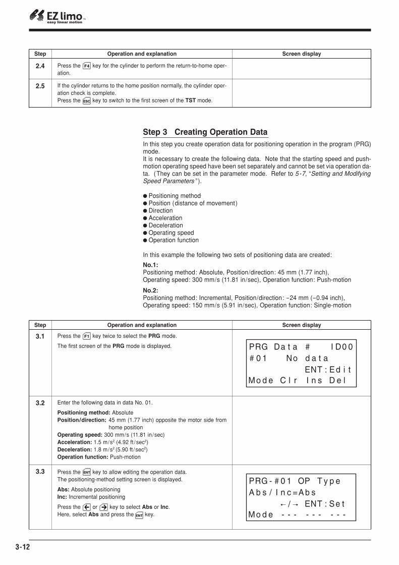
2.4 Press the key for the cylinder to perform the return-to-home oper-ation.
2.5 If the cylinder returns to the home position normally, the cylinder oper-ation check is complete.Press the key to switch to the first screen of the TST mode.
F4
ESC
Screen displayStep Operation and explanation
Step 3 Creating Operation DataIn this step you create operation data for positioning operation in the program (PRG)mode.It is necessary to create the following data. Note that the starting speed and push-motion operating speed have been set separately and cannot be set via operation da-ta. (They can be set in the parameter mode. Refer to 5-7, “Setting and ModifyingSpeed Parameters ”).
� Positioning method� Position (distance of movement)� Direction� Acceleration� Deceleration� Operating speed� Operation function
In this example the following two sets of positioning data are created:
No.1:Positioning method: Absolute, Position/direction: 45 mm (1.77 inch), Operating speed: 300 mm/s (11.81 in/sec), Operation function: Push-motion
No.2:Positioning method: Incremental, Position/direction: -24 mm (-0.94 inch), Operating speed: 150 mm/s (5.91 in/sec), Operation function: Single-motion
3.1
3.2
Press the key twice to select the PRG mode.
The first screen of the PRG mode is displayed.
Enter the following data in data No. 01.
Positioning method: AbsolutePosition/direction: 45 mm (1.77 inch) opposite the motor side from
home positionOperating speed: 300 mm/s (11.81 in/sec)Acceleration: 1.5 m/s2 (4.92 ft /sec2)Deceleration: 1.8 m/s2 (5.90 ft /sec2)Operation function: Push-motion
3.3 Press the key to allow editing the operation data.The positioning-method setting screen is displayed.
Abs: Absolute positioningInc: Incremental positioning
Press the or key to select Abs or Inc.Here, select Abs and press the key.
F1
ENT
ENT
Screen displayStep Operation and explanation
EZS/ EZC Series Controller DATA SETTING MANUAL
Chapter 3 Creating Operation Data and Starting Operation
3-13
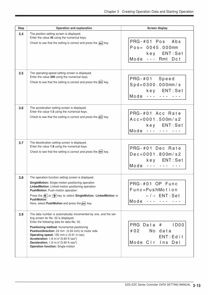
3.4
3.5
3.6
3.7
3.8
3.9
The position setting screen is displayed.Enter the value 45 using the numerical keys.
Check to see that the setting is correct and press the key.
The operating-speed setting screen is displayed.Enter the value 300 using the numerical keys.
Check to see that the setting is correct and press the key.
The acceleration setting screen is displayed.Enter the value 1.5 using the numerical keys.
Check to see that the setting is correct and press the key.
The deceleration setting screen is displayed.Enter the value 1.8 using the numerical keys.
Check to see that the setting is correct and press the key.
The operation-function setting screen is displayed.
SingleMotion: Single-motion positioning operationLinkedMotion: Linked-motion positioning operationPushMotion: Push-motion operation
Press the or key to select SingleMotion, LinkedMotion orPushMotion.Here, select PushMotion and press the key.
The data number is automatically incremented by one, and the set-ting screen for No. 02 is displayed.Enter the following data for data No. 02.
Positioning method: Incremental positioningPosition/direction: 24 mm (0.94 inch) to motor sideOperating speed: 150 mm/s (5.91 in/sec)Acceleration: 1.8 m/s2 (5.90 ft /sec2)Deceleration: 1.8 m/s2 (5.90 ft /sec2)Operation function: Single-motion
ENT
ENT
ENT
ENT
ENT
Screen displayStep Operation and explanation
3-14
3.10
3.11
3.12
3.13
3.14
3.15
The position setting screen is displayed.Enter the value -24 using the numerical keys.
Set the direction of movement using the key.Press the key to display the “- ” symbol.
The default values are as follows:
No display: Opposite the motor side-: Motor side
Check to see that the setting is correct and press the key.
+/-
+/-
ENT
The operating-speed setting screen is displayed.Enter the value 150 using the numerical keys.
Check to see that the setting is correct and press the key.ENT
The acceleration setting screen is displayed.Enter the value 1.8 using the numerical keys.
Check to see that the setting is correct and press the key.ENT
The deceleration setting screen is displayed.Enter the value 1.8 using the numerical keys.
Check to see that the setting is correct and press the key.ENT
The operation-function setting screen is displayed.
SingleMotion: Single-motion positioning operationLinkedMotion: Linked-motion positioning operationPushMotion: Push-motion operation
Press the or key to select SingleMotion, LinkedMotion orPushMotion.Here, select SingleMotion and press the key.ENT
Screen displayStep Operation and explanation
Press the key.The positioning-method setting screen is displayed.
Abs: Absolute positioningInc: Incremental positioning
Press the or key to select Abs or Inc.Here, select Inc and press the key.
ENT
ENT
EZS/ EZC Series Controller DATA SETTING MANUAL
Chapter 3 Creating Operation Data and Starting Operation
3-15
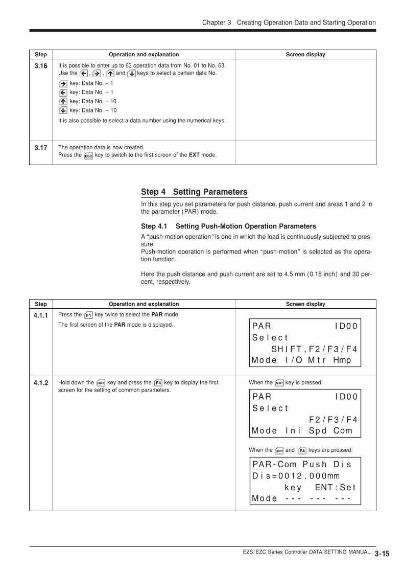
4.1.1
4.1.2
3.16
3.17
It is possible to enter up to 63 operation data from No. 01 to No. 63.Use the , , and keys to select a certain data No.
key: Data No. + 1
key: Data No. - 1
key: Data No. + 10
key: Data No. - 10
It is also possible to select a data number using the numerical keys.
The operation data is now created.Press the key to switch to the first screen of the EXT mode.ESC
Screen displayStep Operation and explanation
Step 4 Setting ParametersIn this step you set parameters for push distance, push current and areas 1 and 2 inthe parameter (PAR) mode.
Step 4.1 Setting Push-Motion Operation ParametersA “push-motion operation” is one in which the load is continuously subjected to pres-sure.Push-motion operation is performed when “push-motion” is selected as the opera-tion function.
Here the push distance and push current are set to 4.5 mm (0.18 inch) and 30 per-cent, respectively.
Screen displayStep Operation and explanation
Press the key twice to select the PAR mode.
The first screen of the PAR mode is displayed.
F1
When the and keys are pressed:
Hold down the key and press the key to display the firstscreen for the setting of common parameters.
SHIFT SHIFT
SHIFT F4
F4 When the key is pressed:
3-16
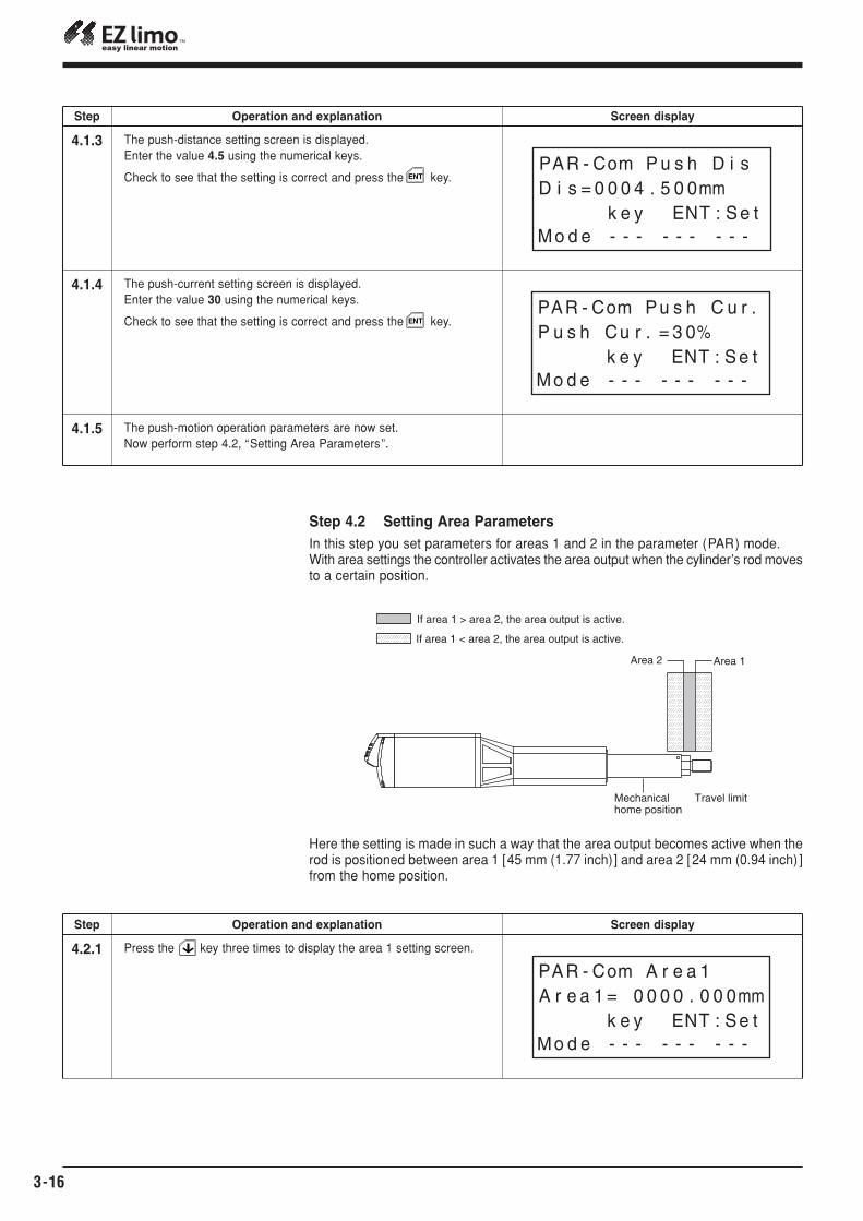
The push-distance setting screen is displayed.Enter the value 4.5 using the numerical keys.
Check to see that the setting is correct and press the key.
4.1.3
4.1.4
4.1.5
ENT
The push-current setting screen is displayed.Enter the value 30 using the numerical keys.
Check to see that the setting is correct and press the key.
The push-motion operation parameters are now set.Now perform step 4.2, “Setting Area Parameters”.
ENT
Step 4.2 Setting Area ParametersIn this step you set parameters for areas 1 and 2 in the parameter (PAR) mode.With area settings the controller activates the area output when the cylinder’s rod movesto a certain position.
4.2.1
Here the setting is made in such a way that the area output becomes active when therod is positioned between area 1 [45 mm (1.77 inch)] and area 2 [24 mm (0.94 inch) ]from the home position.
Mechanical home position
Travel limit
If area 1 > area 2, the area output is active.
If area 1 < area 2, the area output is active.
Area 1Area 2
Screen displayStep Operation and explanation
Screen displayStep Operation and explanation
Press the key three times to display the area 1 setting screen.
EZS/ EZC Series Controller DATA SETTING MANUAL
Chapter 3 Creating Operation Data and Starting Operation
3-17
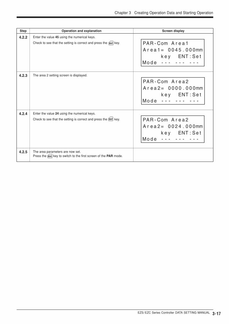
4.2.2
4.2.3
4.2.4
4.2.5
Enter the value 45 using the numerical keys.
Check to see that the setting is correct and press the key.ENT
The area 2 setting screen is displayed.
Enter the value 24 using the numerical keys.
Check to see that the setting is correct and press the key.ENT
The area parameters are now set.Press the key to switch to the first screen of the PAR mode.ESC
Screen displayStep Operation and explanation
3-18
5.1
5.2
Press the key once to select the TST mode.
The first screen of the TST mode is displayed.
Press the key to select positioning operation.
The screen for performing positioning operation is displayed.
Press the key to perform the return-to-home operation.5.3
F1
F4
F4
Check that data No. 01 is displayed, and press the key to performthe positioning operation.
5.4 START
Select data No. 01 or No. 02 using the , , and keys.It is also possible to select a data number using the numerical keys.
Press the key to perform the positioning operation.
5.5
Upon completion of the operations you’ve performed so far, the posi-tioning-operation check is complete.
Press the key to switch to the EXT mode.
5.6
START
F1
Step 5 Performing the Positioning OperationIn this step you perform the cylinder positioning operation in the test (TST) mode.The operation data created in step 3 is called up and used to actually operate the slid-er.Positioning is performed according to the following procedure:
� Return to mechanical home operation� Positioning operation of data No. 01� Positioning operation of data No. 02
Screen displayStep Operation and explanation
EZS/ EZC Series Controller DATA SETTING MANUAL
Description
Positioning method
Position of moving part (mm)
Operating speed (mm/s)
Acceleration (m/s2)
Deceleration (m/s2)
Setting of single-motion positioning operation, linked-motion positioning operation or push-motion operation
Screen display
Abs/Inc
Pos
Spd
Acc
Dec
Func
Item
ABS/INC
Position ( travel amount )
Operating speed
Acceleration
Deceleration
Operation function
4-1
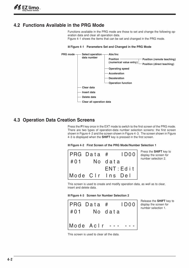
� Table 4-1 Items Set for Data Numbers
The position can be entered in one of the following three ways:�Numerical value input: Enter numerical values using the numerical keys.�Remote teaching input: Operate the slider/cylinder with the arrow keys to enter the
stopping position.�Direct teaching input: Move the slider/cylinder manually to enter the stopping po-
sition.
Chapter 4 Creating and Modifying Operation Data
This chapter explains the procedures involved in setting and modifying operation da-ta, which are performed in the program (PRG) mode.
Chapter 4 Creating and Modifying Operation Data
Warning
� In order to avoid injury and equipment damage, besure that engineers having expert knowledge of thestructure and operation of the EZS/EZC Series con-trollers and sliders/cylinders, along with an awarenessof the degree of risk involved in the operation, performthe connection of the teaching pendant.
4.1 Operation Data Operation data specifies the values necessary for positioning operations, such as po-sition, direction and speed of movement.Operation data created by the teaching pendant is stored in the controller’s memory.It is possible to create up to 63 operation data from No. 1 to No. 63.Table 4-1 lists the items that should be set for each data number.
Abs/Inc
Position (numerical value entry)
Operating speed
Acceleration
Deceleration
Operation function
PRG mode
4-2
� Figure 4-2 First Screen of the PRG Mode/Number Selection 1
Press the SHIFT key to display the screen for number selection 2.
This screen is used to create and modify operation data, as well as to clear, insert and delete data.
� Figure 4-3 Screen for Number Selection 2
Release the SHIFT key todisplay the screen for number selection 1.
This screen is used to clear all the data.
� Figure 4-1 Parameters Set and Changed in the PRG Mode
4.2 Functions Available in the PRG ModeFunctions available in the PRG mode are those to set and change the following op-eration data and clear all operation data. Figure 4-1 shows the items that can be set and changed in the PRG mode.
Select operation data number
Clear data
Insert data
Delete data
Clear all operation data
Position (remote teaching)
Position (direct teaching)
4.3 Operation Data Creation ScreensPress the F1 key once in the EXT mode to switch to the first screen of the PRG mode.There are two types of operation-data number selection screens: the first screenshown in Figure 4-2 and the screen shown in Figure 4-3. The screen shown in Figure4-3 is displayed when the SHIFT key is pressed in the first screen.
EZS/ EZC Series Controller DATA SETTING MANUAL 4-3
Chapter 4 Creating and Modifying Operation Data
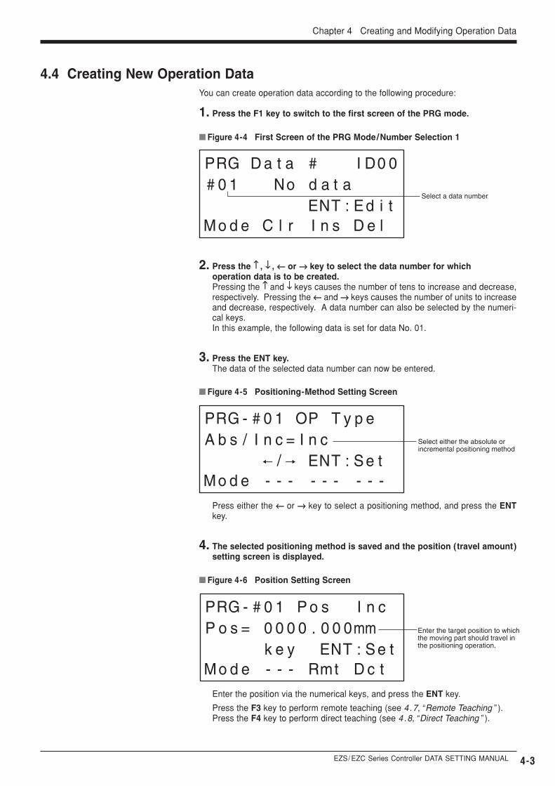
� Figure 4-4 First Screen of the PRG Mode/Number Selection 1
Select a data number
� Figure 4-5 Positioning-Method Setting Screen
� Figure 4-6 Position Setting Screen
Select either the absolute or incremental positioning method
Enter the target position to which the moving part should travel in the positioning operation.
2. Press the ↑↑ , ↓↓ , ←← or →→ key to select the data number for which operation data is to be created.Pressing the ↑↑ and ↓↓ keys causes the number of tens to increase and decrease,respectively. Pressing the ←← and →→ keys causes the number of units to increaseand decrease, respectively. A data number can also be selected by the numeri-cal keys.In this example, the following data is set for data No. 01.
3. Press the ENT key.The data of the selected data number can now be entered.
Press either the ←← or →→ key to select a positioning method, and press the ENTkey.
4. The selected positioning method is saved and the position (travel amount)setting screen is displayed.
Enter the position via the numerical keys, and press the ENT key.
Press the F3 key to perform remote teaching (see 4.7, “Remote Teaching ” ).Press the F4 key to perform direct teaching (see 4.8, “Direct Teaching ” ).
4.4 Creating New Operation DataYou can create operation data according to the following procedure:
1. Press the F1 key to switch to the first screen of the PRG mode.
4-4
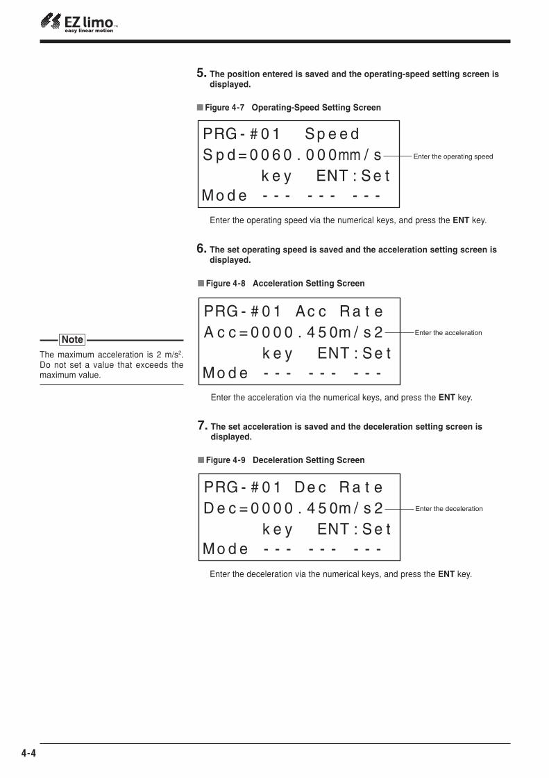
� Figure 4-7 Operating-Speed Setting Screen
Enter the operating speed
5. The position entered is saved and the operating-speed setting screen is displayed.
Enter the operating speed via the numerical keys, and press the ENT key.
� Figure 4-8 Acceleration Setting Screen
Enter the acceleration
6. The set operating speed is saved and the acceleration setting screen is displayed.
Enter the acceleration via the numerical keys, and press the ENT key.
� Figure 4-9 Deceleration Setting Screen
Enter the deceleration
7. The set acceleration is saved and the deceleration setting screen is displayed.
Enter the deceleration via the numerical keys, and press the ENT key.
The maximum acceleration is 2 m/s2.Do not set a value that exceeds themaximum value.
Note
EZS/ EZC Series Controller DATA SETTING MANUAL
Chapter 4 Creating and Modifying Operation Data
4-5
� Figure 4-11 First Screen of the PRG Mode/Number Selection 1
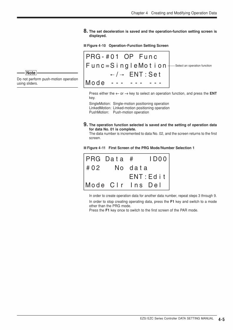
9. The operation function selected is saved and the setting of operation datafor data No. 01 is complete.The data number is incremented to data No. 02, and the screen returns to the firstscreen.
� Figure 4-10 Operation-Function Setting Screen
Select an operation function
8. The set deceleration is saved and the operation-function setting screen isdisplayed.
Press either the ←← or →→ key to select an operation function, and press the ENTkey.
SingleMotion: Single-motion positioning operationLinkedMotion: Linked-motion positioning operationPushMotion: Push-motion operation
In order to create operation data for another data number, repeat steps 3 through 9.
In order to stop creating operating data, press the F1 key and switch to a modeother than the PRG mode.Press the F1 key once to switch to the first screen of the PAR mode.
Do not perform push-motion operationusing sliders.
Note
4-6
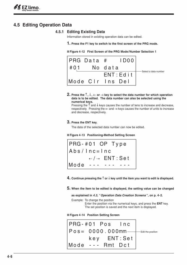
� Figure 4-12 First Screen of the PRG Mode/Number Selection 1
Select a data number
� Figure 4-13 Positioning-Method Setting Screen
� Figure 4-14 Position Setting Screen
Edit the position
2. Press the ↑↑ , ↓↓ , ←← or →→ key to select the data number for which operation data is to be edited. The data number can also be selected using the numerical keys.Pressing the ↑↑ and ↓↓ keys causes the number of tens to increase and decrease,respectively. Pressing the ←← and →→ keys causes the number of units to increaseand decrease, respectively.
3. Press the ENT key.
The data of the selected data number can now be edited.
4. Continue pressing the ↑↑ or ↓↓ key until the item you want to edit is displayed.
5. When the item to be edited is displayed, the setting value can be changed
as explained in 4.3, “Operation Data Creation Screens ”, on p. 4 -2.
Example: To change the positionEnter the position via the numerical keys, and press the ENT key.The set position is saved and the next item is displayed.
4.5 Editing Operation Data4.5.1 Editing Existing Data
Information stored in existing operation data can be edited.
1. Press the F1 key to switch to the first screen of the PRG mode.
EZS/ EZC Series Controller DATA SETTING MANUAL
Chapter 4 Creating and Modifying Operation Data
4-7
6. Press the ENT key.The changed value is saved.
7. Press the ESC or F1 key once you’ve finished editing.If you press the ESC key, the screen will return to the first screen of the PRG mode.If you press the F1 key, the screen will switch to the first screen of the PAR mode.
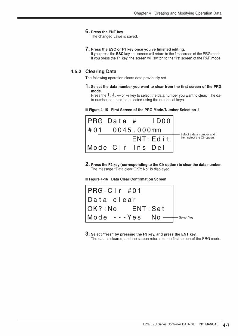
� Figure 4-15 First Screen of the PRG Mode/Number Selection 1
Select a data number and then select the Clr option.
4.5.2 Clearing DataThe following operation clears data previously set.
1. Select the data number you want to clear from the first screen of the PRGmode.Press the ↑↑ , ↓↓ , ←← or →→ key to select the data number you want to clear. The da-ta number can also be selected using the numerical keys.
� Figure 4-16 Data Clear Confirmation Screen
Select Yes
2. Press the F2 key (corresponding to the Clr option) to clear the data number.The message “Data clear OK?: No” is displayed.
3. Select “Yes” by pressing the F3 key, and press the ENT key.The data is cleared, and the screen returns to the first screen of the PRG mode.
4-8
� Figure 4-17 First Screen of the PRG Mode/Number Selection 1
Select a data number and then select the Ins option.
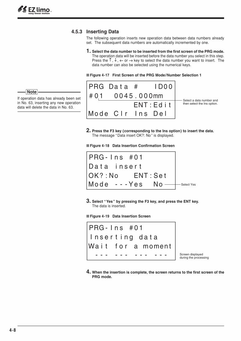
4.5.3 Inserting DataThe following operation inserts new operation data between data numbers alreadyset. The subsequent data numbers are automatically incremented by one.
1. Select the data number to be inserted from the first screen of the PRG mode.The operation data will be inserted before the data number you select in this step.Press the ↑↑ , ↓↓ , ←← or →→ key to select the data number you want to insert. Thedata number can also be selected using the numerical keys.
4. When the insertion is complete, the screen returns to the first screen of thePRG mode.
� Figure 4-18 Data Insertion Confirmation Screen
Select Yes
� Figure 4-19 Data Insertion Screen
Screen displayed during the processing
2. Press the F3 key (corresponding to the Ins option) to insert the data.The message “ Data insert OK?: No ” is displayed.
3. Select “Yes” by pressing the F3 key, and press the ENT key.The data is inserted.
If operation data has already been setin No. 63, inserting any new operationdata will delete the data in No. 63.
Note
EZS/ EZC Series Controller DATA SETTING MANUAL
Chapter 4 Creating and Modifying Operation Data
4-9
� Figure 4-20 First Screen of the PRG Mode/Number Selection 1
Select a data number and then select the Del option.
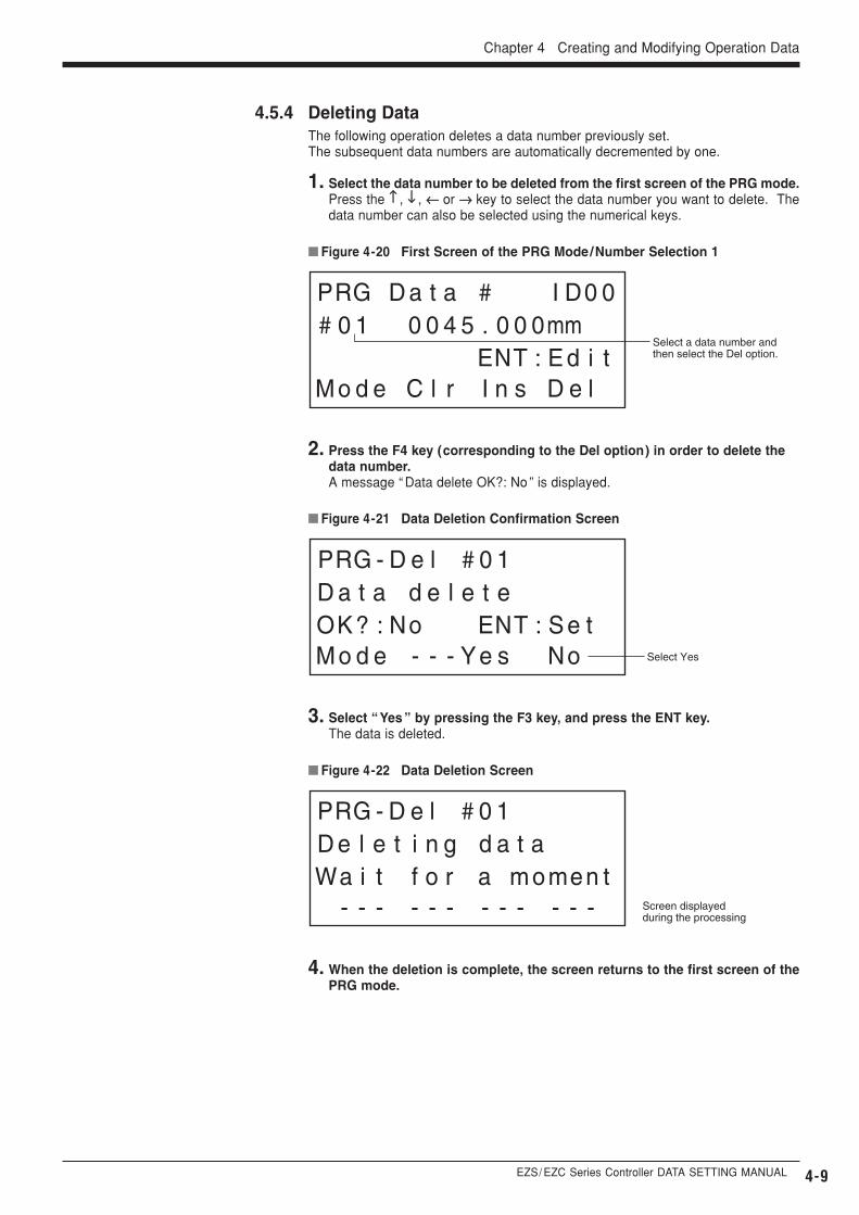
4.5.4 Deleting DataThe following operation deletes a data number previously set.The subsequent data numbers are automatically decremented by one.
1. Select the data number to be deleted from the first screen of the PRG mode.Press the ↑↑ , ↓↓ , ←← or →→ key to select the data number you want to delete. Thedata number can also be selected using the numerical keys.
4. When the deletion is complete, the screen returns to the first screen of thePRG mode.
� Figure 4-21 Data Deletion Confirmation Screen
Select Yes
� Figure 4-22 Data Deletion Screen
Screen displayed during the processing
2. Press the F4 key (corresponding to the Del option) in order to delete the data number.A message “ Data delete OK?: No ” is displayed.
3. Select “ Yes ” by pressing the F3 key, and press the ENT key.The data is deleted.
4-10
� Figure 4-23 Screen for Number Selection 2 of the PRG Mode
Select the Aclr option
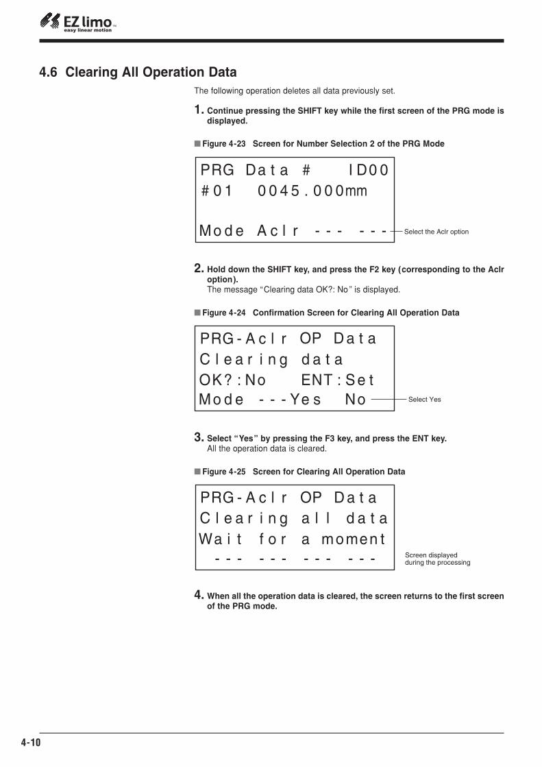
4. When all the operation data is cleared, the screen returns to the first screenof the PRG mode.
� Figure 4-24 Confirmation Screen for Clearing All Operation Data
Select Yes
� Figure 4-25 Screen for Clearing All Operation Data
Screen displayed during the processing
2. Hold down the SHIFT key, and press the F2 key (corresponding to the Aclroption).The message “Clearing data OK?: No ” is displayed.
3. Select “Yes” by pressing the F3 key, and press the ENT key.All the operation data is cleared.
4.6 Clearing All Operation DataThe following operation deletes all data previously set.
1. Continue pressing the SHIFT key while the first screen of the PRG mode isdisplayed.
EZS/ EZC Series Controller DATA SETTING MANUAL
Chapter 4 Creating and Modifying Operation Data
4-11
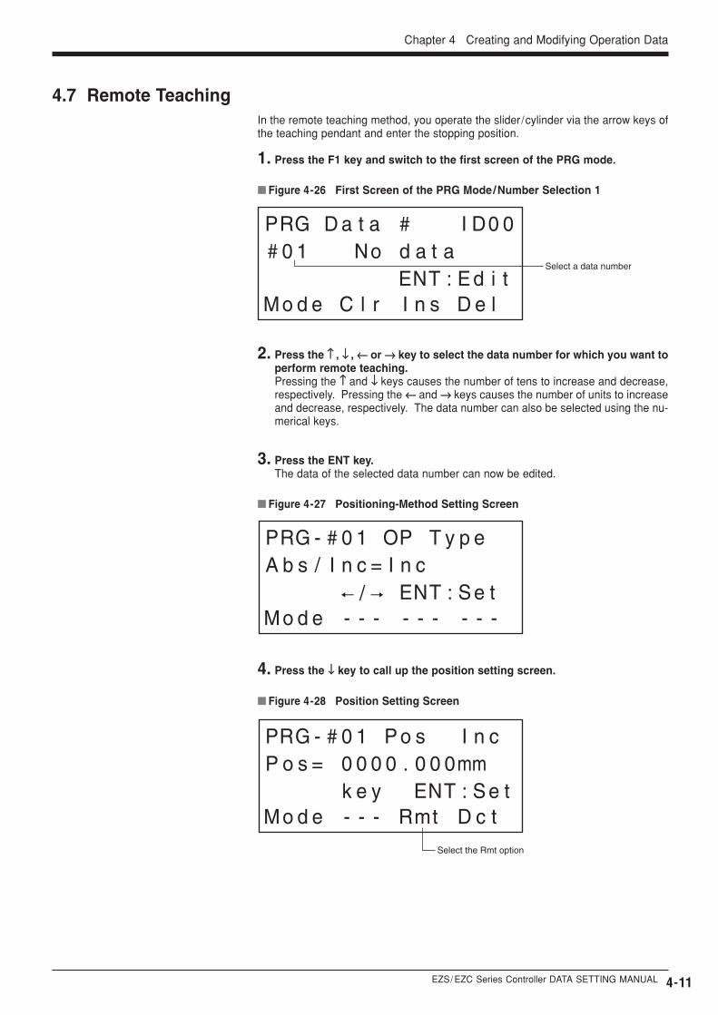
4.7 Remote Teaching
� Figure 4-26 First Screen of the PRG Mode/Number Selection 1
Select a data number
� Figure 4-27 Positioning-Method Setting Screen
� Figure 4-28 Position Setting Screen
Select the Rmt option
2. Press the ↑↑ , ↓↓ , ←← or →→ key to select the data number for which you want toperform remote teaching. Pressing the ↑↑ and ↓↓ keys causes the number of tens to increase and decrease,respectively. Pressing the ←← and →→ keys causes the number of units to increaseand decrease, respectively. The data number can also be selected using the nu-merical keys.
3. Press the ENT key.The data of the selected data number can now be edited.
4. Press the ↓↓ key to call up the position setting screen.
In the remote teaching method, you operate the slider/cylinder via the arrow keys ofthe teaching pendant and enter the stopping position.
1. Press the F1 key and switch to the first screen of the PRG mode.
4-12
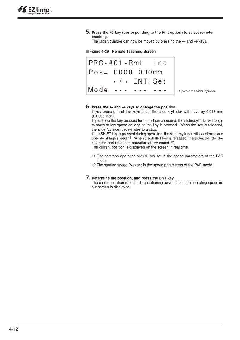
6. Press the ←← and →→ keys to change the position.If you press one of the keys once, the slider/cylinder will move by 0.015 mm(0.0006 inch).If you keep the key pressed for more than a second, the slider/cylinder will beginto move at low speed as long as the key is pressed. When the key is released,the slider/cylinder decelerates to a stop.If the SHIFT key is pressed during operation, the slider/cylinder will accelerate andoperate at high speed ∗1. When the SHIFT key is released, the slider/cylinder de-celerates and returns to operation at low speed ∗2.The current position is displayed on the screen in real time.
∗1 The common operating speed (Vr) set in the speed parameters of the PARmode
∗2 The starting speed (Vs) set in the speed parameters of the PAR mode
7. Determine the position, and press the ENT key.The current position is set as the positioning position, and the operating-speed in-put screen is displayed.
� Figure 4-29 Remote Teaching Screen
Operate the slider/cylinder
5. Press the F3 key (corresponding to the Rmt option) to select remote teaching.The slider/cylinder can now be moved by pressing the ←← and →→ keys.
EZS/ EZC Series Controller DATA SETTING MANUAL
Chapter 4 Creating and Modifying Operation Data
4-13
4.8 Direct Teaching
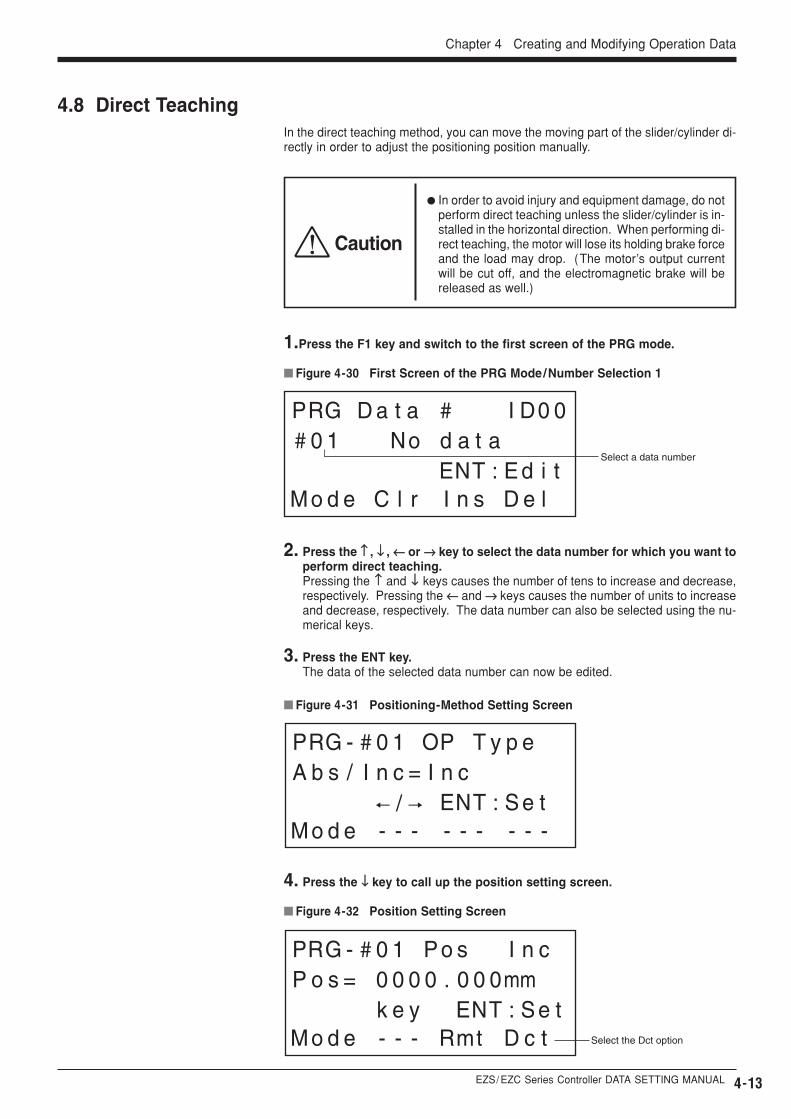
� Figure 4-30 First Screen of the PRG Mode/Number Selection 1
Select a data number
� Figure 4-31 Positioning-Method Setting Screen
� Figure 4-32 Position Setting Screen
Select the Dct option
2. Press the ↑↑ , ↓↓ , ←← or →→ key to select the data number for which you want toperform direct teaching.Pressing the ↑↑ and ↓↓ keys causes the number of tens to increase and decrease,respectively. Pressing the ←← and →→ keys causes the number of units to increaseand decrease, respectively. The data number can also be selected using the nu-merical keys.
3. Press the ENT key.The data of the selected data number can now be edited.
4. Press the ↓↓ key to call up the position setting screen.
In the direct teaching method, you can move the moving part of the slider/cylinder di-rectly in order to adjust the positioning position manually.
1.Press the F1 key and switch to the first screen of the PRG mode.
Caution
� In order to avoid injury and equipment damage, do notperform direct teaching unless the slider/cylinder is in-stalled in the horizontal direction. When performing di-rect teaching, the motor will lose its holding brake forceand the load may drop. (The motor’s output currentwill be cut off, and the electromagnetic brake will bereleased as well.)
4-14
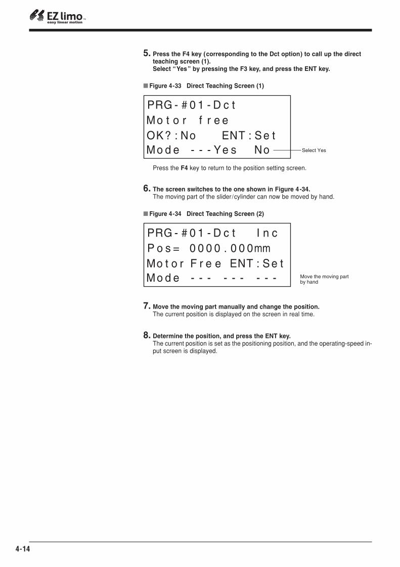
7. Move the moving part manually and change the position.The current position is displayed on the screen in real time.
8. Determine the position, and press the ENT key.The current position is set as the positioning position, and the operating-speed in-put screen is displayed.
� Figure 4-33 Direct Teaching Screen (1)
Select Yes
5. Press the F4 key (corresponding to the Dct option) to call up the direct teaching screen (1).Select “Yes” by pressing the F3 key, and press the ENT key.
� Figure 4-34 Direct Teaching Screen (2)
Move the moving part by hand
6. The screen switches to the one shown in Figure 4-34.The moving part of the slider/cylinder can now be moved by hand.
Press the F4 key to return to the position setting screen.
EZS/ EZC Series Controller DATA SETTING MANUAL
Chapter 4 Creating and Modifying Operation Data
4-15
DescriptionDisplayData
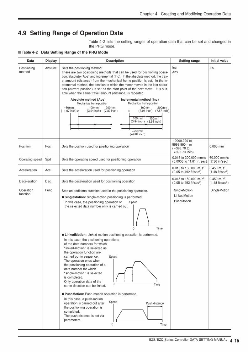
� Table 4-2 Data Setting Range of the PRG Mode
Setting range Initial value
Sets the position used for positioning operationPosPosition
-9999.990 to9999.990 mm(-393.70 to+393.70 inch)
0.000 mm
Sets the positioning method.There are two positioning methods that can be used for positioning opera-tion: absolute (Abs) and incremental (Inc). In the absolute method, the trav-el amount (distance) from the mechanical home position is set. In the in-cremental method, the position to which the motor moved in the last opera-tion (current position) is set as the start point of the next move. It is suit-able when the same travel amount (distance) is repeated.
Sets the operating speed used for positioning operation
Sets the acceleration used for positioning operation
Abs/ IncPositioning method
IncAbs
Inc
SpdOperating speed 0.015 to 300.000 mm/s(0.0006 to 11.81 in/sec)
60.000 mm/s(2.36 in/sec)
AccAcceleration0.015 to 150.000 m/s2
(0.05 to 492 ft /sec2)0.450 m/s2
(1.48 ft /sec2)
Sets the deceleration used for positioning operation
Sets an additional function used in the positioning operation.
� SingleMotion: Single-motion positioning is performed.
In this case, the positioning operation of the selected data number only is carried out.
� LinkedMotion: Linked-motion positioning operation is performed.
In this case, the positioning operations of the data numbers for which “ linked-motion” is selected as the operation function are carried out in sequence. The operation ends when the positioning operation of a data number for which “single-motion” is selected is completed. Only operation data of the same direction can be linked.
0.015 to 150.000 m/s2
(0.05 to 492 ft /sec2)0.450 m/s2
(1.48 ft /sec2)DecDeceleration
FuncOperation function
SingleMotion
LinkedMotion
PushMotion
SingleMotion
� PushMotion: Push-motion operation is performed.
In this case, a push-motion operation is carried out after the positioning operation is completed.The push distance is set via parameters.
0
Speed
Time
Push distance
0
Speed
Time
Speed
0 Time
Mechanical home position Mechanical home positionAbsolute method (Abs) Incremental method (Inc)
0200mm
(7.87 inch)100mm
(3.94 inch)200mm
(7.87 inch)100mm
(3.94 inch)-50mm
(-1.97 inch)
100mm(3.94 inch)
100mm(3.94 inch)
-250mm(-9.84 inch)
0
4.9 Setting Range of Operation DataTable 4-2 lists the setting ranges of operation data that can be set and changed inthe PRG mode.
4-16
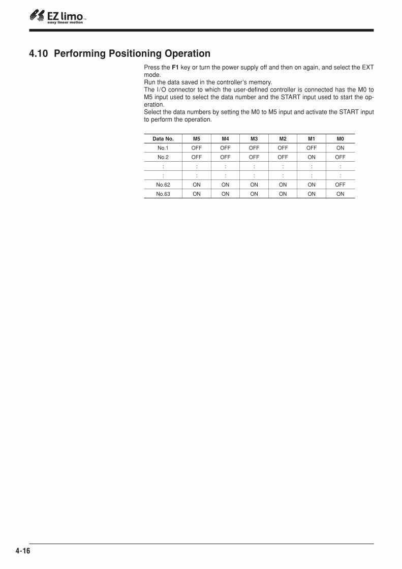
Press the F1 key or turn the power supply off and then on again, and select the EXTmode.Run the data saved in the controller’s memory.The I/O connector to which the user-defined controller is connected has the M0 toM5 input used to select the data number and the START input used to start the op-eration.Select the data numbers by setting the M0 to M5 input and activate the START inputto perform the operation.
M5
OFF
OFF
:
:
ON
ON
M4
OFF
OFF
:
:
ON
ON
M3
OFF
OFF
:
:
ON
ON
M2
OFF
OFF
:
:
ON
ON
M1
OFF
ON
:
:
ON
ON
M0
ON
OFF
:
:
OFF
ON
Data No.
No.1
No.2
:
:
No.62
No.63
4.10 Performing Positioning Operation
EZS/ EZC Series Controller DATA SETTING MANUAL 5-1
� Figure 5-1 Parameters Set and Changed in the PAR Mode
Chapter 5 Setting and Modifying Parameters
This chapter explains the procedures involved in setting and changing parameters,which are performed in the PAR mode.
Chapter 5 Setting and Modifying Parameters
Warning
� In order to avoid injury and equipment damage, besure that engineers having expert knowledge of thestructure and operation of the EZS/EZC Series con-trollers and sliders/cylinders, along with an awarenessof the degree of risk involved in the operation, performthe connection of the teaching pendant.
5.1 Parameters In order to operate sliders/cylinders, it is necessary to set not only operation data butdata that defines the slider/cylinder operating environment. Such data is referred toas parameters.
There are five types of parameters: common parameters intrinsic to the slider/cylin-der; motor parameters that specify the motor current; speed parameters relating tothe operating speed; I /O parameters relating to control; and home parameters relat-ing to return-to-home operation. The speed parameters are commonly used in posi-tioning and return-to-home operations.
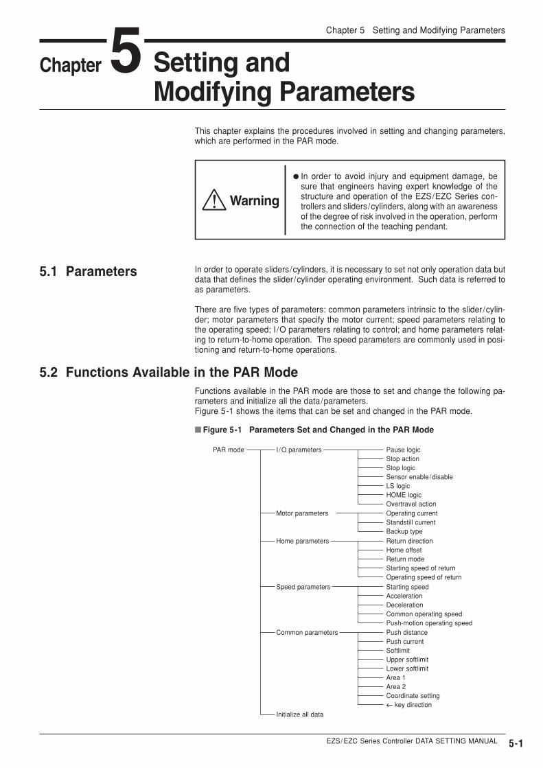
5.2 Functions Available in the PAR ModeFunctions available in the PAR mode are those to set and change the following pa-rameters and initialize all the data/parameters.Figure 5-1 shows the items that can be set and changed in the PAR mode.
PAR mode I /O parameters Pause logicStop actionStop logicSensor enable /disableLS logicHOME logicOvertravel action
Home parameters Return directionHome offsetReturn modeStarting speed of returnOperating speed of return
Motor parameters Operating currentStandstill currentBackup type
Speed parameters Starting speedAccelerationDecelerationCommon operating speedPush-motion operating speed
Common parameters Push distancePush currentSoftlimitUpper softlimitLower softlimitArea 1Area 2Coordinate setting←← key direction
Initialize all data
5-2
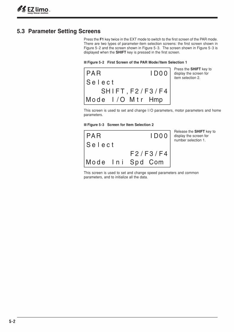
� Figure 5-2 First Screen of the PAR Mode/ Item Selection 1
Press the SHIFT key to display the screen for item selection 2.
This screen is used to set and change I /O parameters, motor parameters and homeparameters.
� Figure 5-3 Screen for Item Selection 2
Release the SHIFT key todisplay the screen for number selection 1.
This screen is used to set and change speed parameters and commonparameters, and to initialize all the data.
5.3 Parameter Setting ScreensPress the F1 key twice in the EXT mode to switch to the first screen of the PAR mode.There are two types of parameter-item selection screens: the first screen shown inFigure 5-2 and the screen shown in Figure 5-3. The screen shown in Figure 5-3 isdisplayed when the SHIFT key is pressed in the first screen.
EZS/ EZC Series Controller DATA SETTING MANUAL
Chapter 5 Setting and Modifying Parameters
5-3
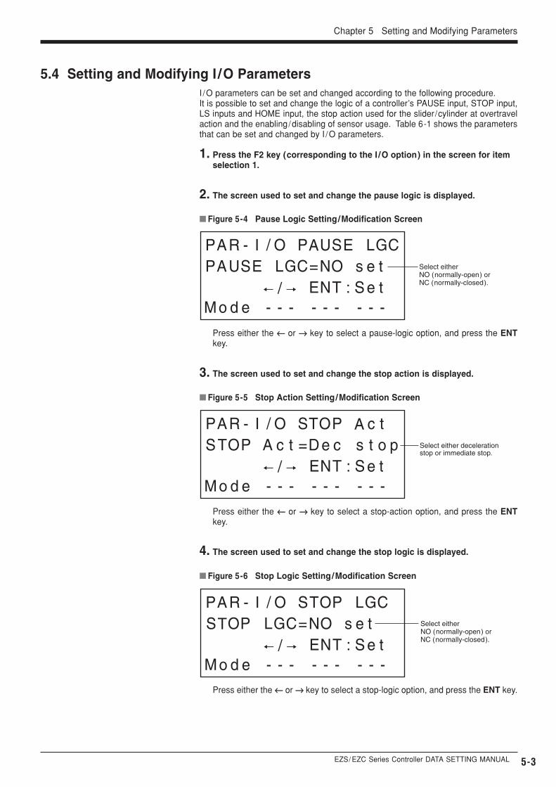
5.4 Setting and Modifying I /O Parameters
� Figure 5-4 Pause Logic Setting/Modification Screen
Select either NO (normally-open) orNC (normally-closed).
� Figure 5-5 Stop Action Setting/Modification Screen
� Figure 5-6 Stop Logic Setting/Modification Screen
Select either deceleration stop or immediate stop.
Select either NO (normally-open) orNC (normally-closed).
3. The screen used to set and change the stop action is displayed.
4. The screen used to set and change the stop logic is displayed.
I /O parameters can be set and changed according to the following procedure.It is possible to set and change the logic of a controller’s PAUSE input, STOP input,LS inputs and HOME input, the stop action used for the slider/cylinder at overtravelaction and the enabling /disabling of sensor usage. Table 6-1 shows the parametersthat can be set and changed by I /O parameters.
1. Press the F2 key (corresponding to the I /O option) in the screen for item selection 1.
2. The screen used to set and change the pause logic is displayed.
Press either the ←← or →→ key to select a stop-logic option, and press the ENT key.
Press either the ←← or →→ key to select a pause-logic option, and press the ENTkey.
Press either the ←← or →→ key to select a stop-action option, and press the ENTkey.
5-4
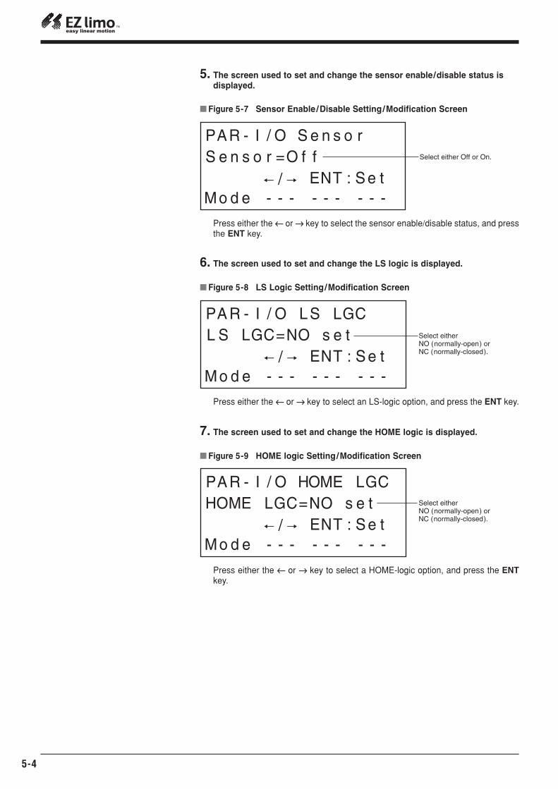
� Figure 5-7 Sensor Enable /Disable Setting/Modification Screen
Select either Off or On.
5. The screen used to set and change the sensor enable/disable status is displayed.
Press either the ←← or →→ key to select the sensor enable/disable status, and pressthe ENT key.
� Figure 5-8 LS Logic Setting/Modification Screen
Select either NO (normally-open) orNC (normally-closed).
6. The screen used to set and change the LS logic is displayed.
Press either the ←← or →→ key to select an LS-logic option, and press the ENT key.
� Figure 5-9 HOME logic Setting/Modification Screen
Select either NO (normally-open) orNC (normally-closed).
7. The screen used to set and change the HOME logic is displayed.
Press either the ←← or →→ key to select a HOME-logic option, and press the ENTkey.
EZS/ EZC Series Controller DATA SETTING MANUAL
Chapter 5 Setting and Modifying Parameters
5-5
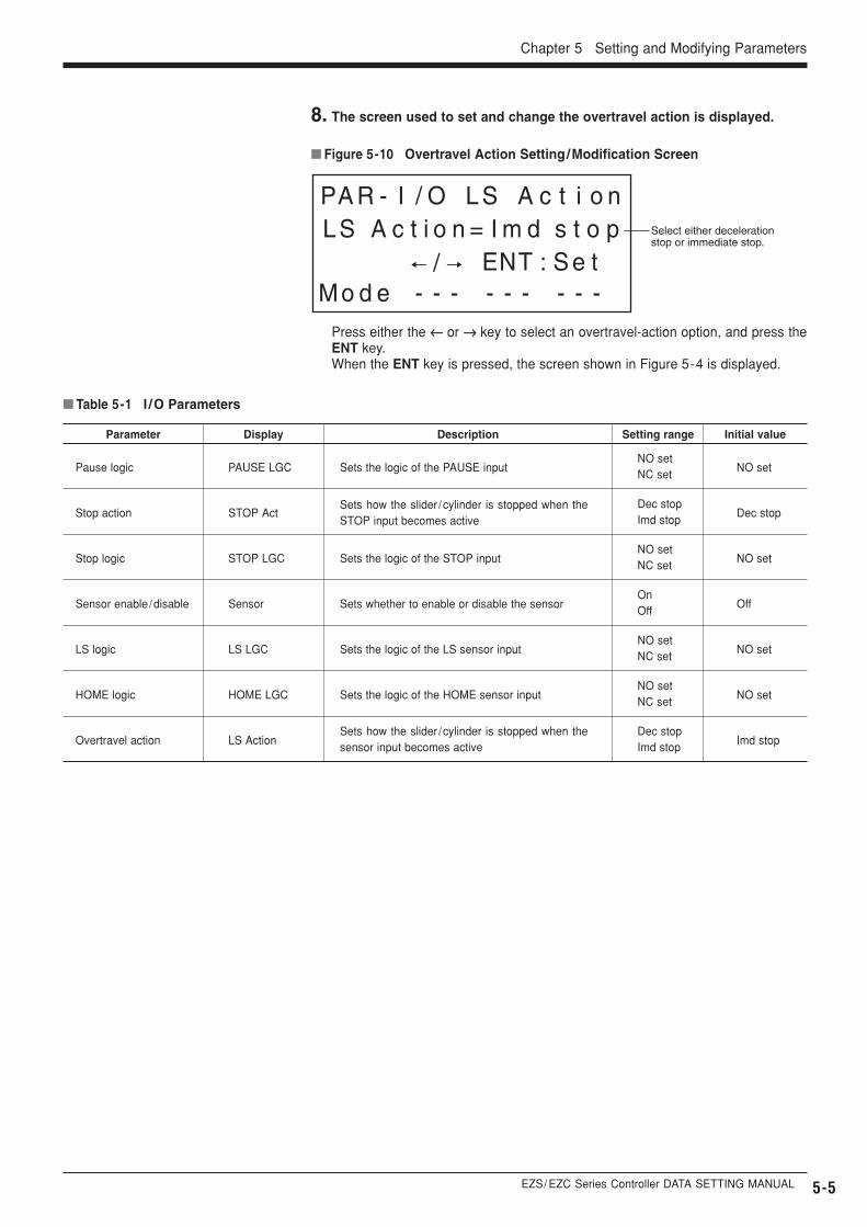
� Figure 5-10 Overtravel Action Setting/Modification Screen
Select either deceleration stop or immediate stop.
8. The screen used to set and change the overtravel action is displayed.
Press either the ←← or →→ key to select an overtravel-action option, and press theENT key.When the ENT key is pressed, the screen shown in Figure 5-4 is displayed.
DescriptionDisplayParameter
� Table 5-1 I /O Parameters
Setting range Initial value
Sets the logic of the PAUSE inputPAUSE LGCPause logicNO setNC set
NO set
Sets how the slider /cylinder is stopped when theSTOP input becomes active
STOP ActStop actionDec stopImd stop
Dec stop
Sets the logic of the STOP inputSTOP LGCStop logicNO setNC set
NO set
Sets whether to enable or disable the sensorSensorSensor enable /disableOnOff
Off
Sets the logic of the LS sensor inputLS LGCLS logicNO setNC set
NO set
Sets the logic of the HOME sensor inputHOME LGCHOME logicNO setNC set
NO set
Sets how the slider /cylinder is stopped when thesensor input becomes active
LS ActionOvertravel actionDec stopImd stop
Imd stop
5-6
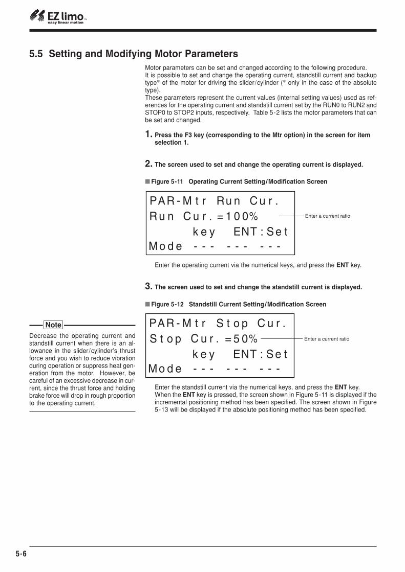
5.5 Setting and Modifying Motor Parameters
� Figure 5-11 Operating Current Setting/Modification Screen
Enter a current ratio
� Figure 5-12 Standstill Current Setting/Modification Screen
Enter a current ratio
3. The screen used to set and change the standstill current is displayed.
Motor parameters can be set and changed according to the following procedure.It is possible to set and change the operating current, standstill current and backuptype∗ of the motor for driving the slider/cylinder (∗ only in the case of the absolutetype).These parameters represent the current values (internal setting values) used as ref-erences for the operating current and standstill current set by the RUN0 to RUN2 andSTOP0 to STOP2 inputs, respectively. Table 5-2 lists the motor parameters that canbe set and changed.
1. Press the F3 key (corresponding to the Mtr option) in the screen for item selection 1.
2. The screen used to set and change the operating current is displayed.
Enter the operating current via the numerical keys, and press the ENT key.
Enter the standstill current via the numerical keys, and press the ENT key.When the ENT key is pressed, the screen shown in Figure 5-11 is displayed if theincremental positioning method has been specified. The screen shown in Figure5-13 will be displayed if the absolute positioning method has been specified.
Decrease the operating current andstandstill current when there is an al-lowance in the slider/cylinder’s thrustforce and you wish to reduce vibrationduring operation or suppress heat gen-eration from the motor. However, becareful of an excessive decrease in cur-rent, since the thrust force and holdingbrake force will drop in rough proportionto the operating current.
Note
EZS/ EZC Series Controller DATA SETTING MANUAL
Chapter 5 Setting and Modifying Parameters
5-7
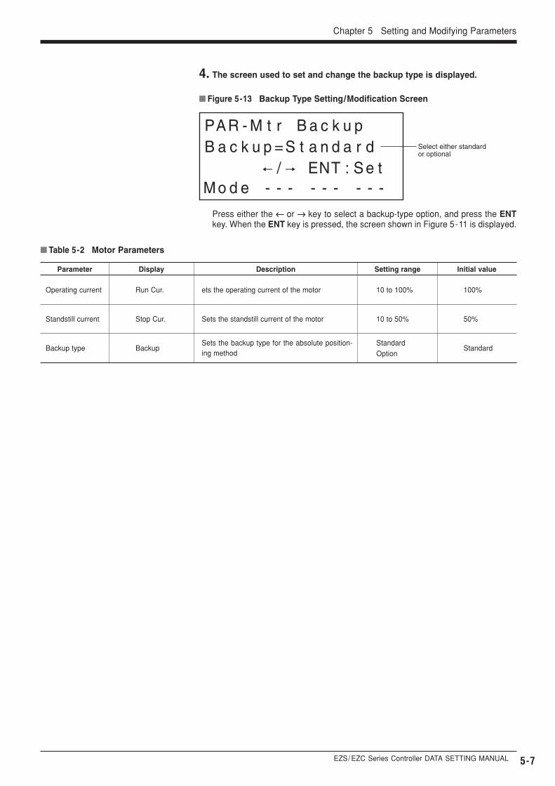
� Figure 5-13 Backup Type Setting/Modification Screen
Select either standard or optional
4. The screen used to set and change the backup type is displayed.
Press either the ←← or →→ key to select a backup-type option, and press the ENTkey. When the ENT key is pressed, the screen shown in Figure 5-11 is displayed.
DescriptionDisplayParameter
� Table 5-2 Motor Parameters
Setting range Initial value
ets the operating current of the motorRun Cur.Operating current 10 to 100% 100%
Sets the standstill current of the motorStop Cur.Standstill current 10 to 50% 50%
Sets the backup type for the absolute position-ing method
BackupBackup typeStandardOption
Standard
5-8
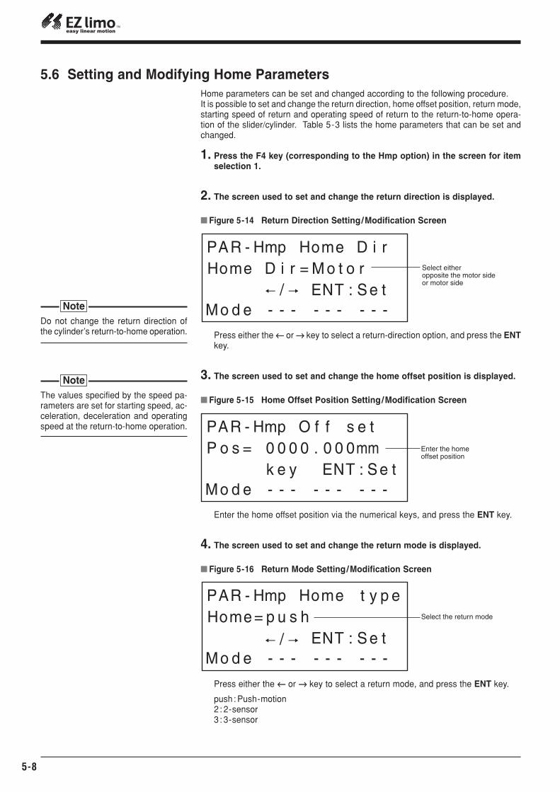
5.6 Setting and Modifying Home Parameters
� Figure 5-14 Return Direction Setting/Modification Screen
Select either opposite the motor side or motor side
� Figure 5-15 Home Offset Position Setting/Modification Screen
Enter the home offset position
3. The screen used to set and change the home offset position is displayed.
Home parameters can be set and changed according to the following procedure.It is possible to set and change the return direction, home offset position, return mode,starting speed of return and operating speed of return to the return-to-home opera-tion of the slider/cylinder. Table 5-3 lists the home parameters that can be set andchanged.
1. Press the F4 key (corresponding to the Hmp option) in the screen for itemselection 1.
2. The screen used to set and change the return direction is displayed.
Press either the ←← or →→ key to select a return-direction option, and press the ENTkey.
Enter the home offset position via the numerical keys, and press the ENT key.
� Figure 5-16 Return Mode Setting/Modification Screen
Select the return mode
4. The screen used to set and change the return mode is displayed.
Press either the ←← or →→ key to select a return mode, and press the ENT key.
push: Push-motion2: 2-sensor3 : 3-sensor
Do not change the return direction ofthe cylinder’s return-to-home operation.
Note
The values specified by the speed pa-rameters are set for starting speed, ac-celeration, deceleration and operatingspeed at the return-to-home operation.
Note
EZS/ EZC Series Controller DATA SETTING MANUAL 5-9
Chapter 5 Setting and Modifying Parameters
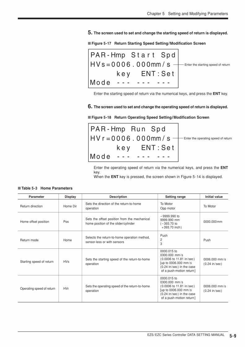
DescriptionDisplayParameter
� Table 5-3 Home Parameters
Setting range Initial value
Sets the direction of the return-to-home operation
Home DirReturn directionTo MotorOpp motor
To Motor
Sets the offset position from the mechanicalhome position of the slider/cylinderPosHome offset position
-9999.990 to9999.990 mm(-393.70 to+393.70 inch)
0000.000mm
Selects the return-to-home operation method,sensor-less or with sensorsHomeReturn mode
Push23
Push
Sets the starting speed of the return-to-homeoperation
HVsStarting speed of return
0000.015 to0300.000 mm/s(0.0006 to 11.81 in/sec)[up to 0006.000 mm/s (0.24 in/sec) in the case of a push-motion return ]
0006.000 mm/s(0.24 in/sec)
Sets the operating speed of the return-to-homeoperation
HVrOperating speed of return
0000.015 to0300.000 mm/s(0.0006 to 11.81 in/sec)[up to 0006.000 mm/s (0.24 in/sec) in the case of a push-motion return ]
0006.000 mm/s(0.24 in/sec)
� Figure 5-17 Return Starting Speed Setting/Modification Screen
Enter the starting speed of return
5. The screen used to set and change the starting speed of return is displayed.
Enter the starting speed of return via the numerical keys, and press the ENT key.
� Figure 5-18 Return Operating Speed Setting/Modification Screen
Enter the operating speed of return
6. The screen used to set and change the operating speed of return is displayed.
Enter the operating speed of return via the numerical keys, and press the ENTkey.When the ENT key is pressed, the screen shown in Figure 5-14 is displayed.
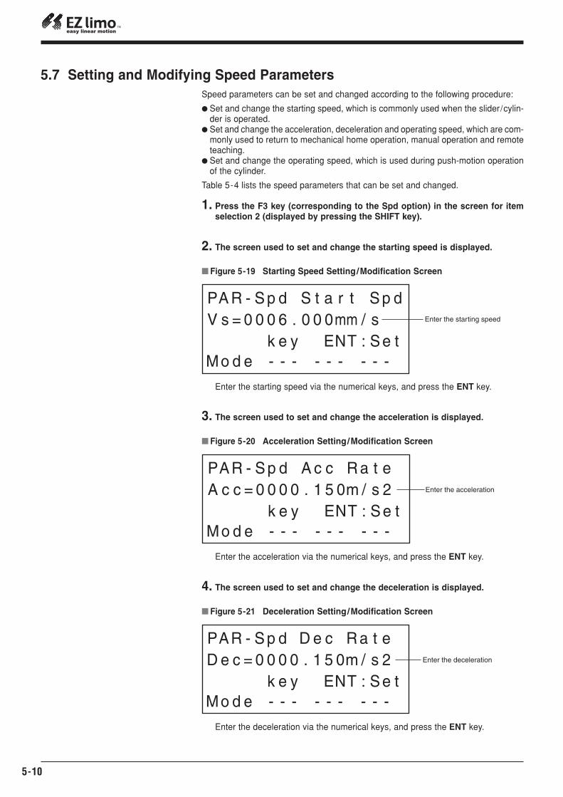
5-10
5.7 Setting and Modifying Speed Parameters
� Figure 5-19 Starting Speed Setting/Modification Screen
Enter the starting speed
� Figure 5-20 Acceleration Setting/Modification Screen
Enter the acceleration
3. The screen used to set and change the acceleration is displayed.
Speed parameters can be set and changed according to the following procedure:
� Set and change the starting speed, which is commonly used when the slider/cylin-der is operated.
� Set and change the acceleration, deceleration and operating speed, which are com-monly used to return to mechanical home operation, manual operation and remoteteaching.
� Set and change the operating speed, which is used during push-motion operationof the cylinder.
Table 5-4 lists the speed parameters that can be set and changed.
1. Press the F3 key (corresponding to the Spd option) in the screen for itemselection 2 (displayed by pressing the SHIFT key).
2. The screen used to set and change the starting speed is displayed.
Enter the starting speed via the numerical keys, and press the ENT key.
Enter the acceleration via the numerical keys, and press the ENT key.
� Figure 5-21 Deceleration Setting/Modification Screen
Enter the deceleration
4. The screen used to set and change the deceleration is displayed.
Enter the deceleration via the numerical keys, and press the ENT key.