Embed Size (px)
Citation preview

2011/04
EZREZR
www.vulkandrivetech.com
BrazilVULKAN do Brasil Ltda.Rod. Engº Constancio Cintra, km 91Bairro da Ponte – Cx Postal 141CEP 13252-200 Itatiba, São Paulo/BrasilTel. +55 11 4894-7300 · Fax +55 11 4894-7329E-Mail: [email protected]
ItalyVULKAN Italia S.R.L.Via dell´ Agricoltura 2P. O. Box 315067 Novi Ligure (AL)/ItalyTel. +39 0143 310211 · Fax +39 0143 329740E-Mail: [email protected]
IndiaVulkan Technologies Pvt Ltd S.No.539-B ,Kasar Amboli ,Tal.Mulshi Pirangut Industrial Area .Ghotawade Dist Pune -412111 - India Tel. -[91-20 ] 66765526 - Fax -[91-20] 66765551 E-mail: [email protected]
KoreaVULKAN Korea Co.4th floor, Samsung Haeundae Bldg.1153-8, Jung 1-Dong, Haundae-GuBusan 612-847,KoreaTel. +82 51 2562473 ˆ Fax +82 51 2562474E-Mail: [email protected]
GermanyVULKAN Kupplungs- undGetriebebau GmbH & Co. KGHeerstr. 6644653 Herne/GermanyTel. +49 2325 922-0 · Fax +49 2325 71110E-Mail: [email protected]
United KingdomVULKAN Industries LTDArcher RoadArmytage Road Industrial Estate,Brighouse, W.-Yorkshire, HD6 1XF/GBTel. +44 1484 712273 - Fax +44 1484 711376E-Mail: [email protected]
ChinaWuxi VULKAN Technologies Co. Ltd.Xinzhou Road, Lot 93D-3 in Wuxi Science & TechnologyIndustrial Park, 214028 Jiangsu Prov. P.R. ChinaTel. +86 510 8534 2222 ˆ Fax +86 510 8534 2345E-Mail: [email protected]
FranceVULKAN France SA12, avenue Émile ZolaZA de l'Agavon13170 Les Pennes Mirabeau/FranceTel. +33 04 42 02 21 01 . Fax +33 04 42 02 21 09E-Mail: [email protected]
U.S.A. American VULKAN Corporation2525 Dundee RoadWinter Haven, Florida 33884/USATel. +1 863 3242424 · Fax +1 863 3244008E-Mail: [email protected]
SpainVULKAN Española S.A.Polig. Ind. MoscatelaresAvda. Montes de Oca, 19, Nave 728709 S.S. Reyes, Madrid/SpainTel. +34 91 3590971/72 · Fax +34 91 3453182E-Mail: [email protected]
Netherlands, Belgium, LuxembourgVULKAN BeneluxVan Coulsterweg 32952 CB Alblasserdam / NetherlandsTel. + 31 (0) 78 68 107 80 – Fax +31 (0) 78 68 107 99E-Mail: [email protected]
South AfricaVULKAN South AfricaUnit H6 Pinelands Office ParkArdeer RoadModderfontein,EdenvaleJohannesburg, South AfricaTel: +27 11-6084044 - Fax: +27 11-6081877E-Mail: [email protected]

3902
Der vorliegende Katalog ersetzt alle vorherigen Ausgaben, ältereDrucke verlieren ihre Gültigkeit.
Die Angaben in diesem Katalog beziehen sich auf den technischenStandard gültig im Hause VULKAN und unter den definiertenBedingungen laut Erläuterung im Katalog – es liegt im Ent-scheidungs-und Verantwortungsrahmen des Systemverantwort-lichen für die Antriebslinie entsprechende Rückschlüsse auf dasSystemverhalten zu ziehen. VULKAN Drehschwingungsanalysenberücksichtigen in der Regel nur das rein mechanische Schwin-gungsersatzsystem – als ein Komponentenhersteller übernimmtVULKAN mit der Analyse des Drehschwingungssystems (statio-när, transient) nicht die Systemverantwortung – die Genauigkeitder Analyse hängt von der Genauigkeit der verwendeten bzw. derVULKAN zur Verfügung gestellten Daten ab.
Änderungen aufgrund des technischen Fortschritts sind vorbe-halten. Bei Unklarheiten bzw. Rückfragen kontaktieren Sie bitteVULKAN.
This catalogue supersedes previous editions. VULKAN reserves the right toamend any details in this catalogue without notice and with-outany liability for previously supplied couplings.
The data in this catalogue refers to the technical standard as pre-sent-ly used by VULKAN with defined conditions according to theexplanations in the catalogue. The responsibility for the torsionalvibration compatibility of the complete system rest with the systemadministrator who has the responsibility and competence to makethe necessary calculation for the drive line behaviour. VULKAN tor-sional vibration analysis usually only consider the pure mechanicalmass-elastic system. As a c omponent supplier VULKAN takes nosystem responsibility according to the analysis of the torsional vibra-tionsystem (stationary, transiently). The accuracy of the analysisdepends on the exactness of the used data resp. the provided datas toVULKAN.
Any changes due to the technological progress are reserved. For ques-tions or unclear items please contact VULKAN.
Stand 04/2011Das Recht auf Vervielfältigung, Nachdruck und Übersetzungenbehalten wir uns vor.
Maß- und Konstruktionsänderungen vorbehalten.
Issue 04/2011All rights of duplication, reprinting and translation are reserved.
We reserve the right to modify dimensions and constructions withoutprior notice.
EZR
2011
/04
Hochelastische VULKAN KupplungenHighly Flexible VULKAN Couplings
Maß- und Konstruktionsänderungen vorbehalten.VULKAN reserves the right to change shapes, values and construction dimensions without prior notice..
Die hochelastische MEGIFLEX-B-Kupplung ist in alle Richtungennachgiebig. Sie wird als Flansch-Welle- oder Welle-Welle-Verbin-dung eingesetzt.
Drehmomentbereich: 0,01 - 3,15 kNmLieferbar in Gummi- oder Silikonausführung.
VULKARDAN-LVorschaltkupplung mit linearer Drehsteifi gkeit.
Drehmomentbereich: 0.16-12.5 kNm
VULKARDAN-PVorschaltkupplung mit progressiver Drehsteifi gkeit.
Drehmomentbereich: 0.32-31.5 kNm
Anfl anschaußenlagermit hochelastischer KupplungDiese Ausführung wird bei Antriebsanlagen mit hohem Beugewinkelder Gelenkwelle verwendet. Die durch die Gelenkwelle entstehen-den Reaktionskräfte werden durch das Anfl anschaußenlager aufgenom-men und reduzieren somit die Kurbelwellenbeanspruchung.
Drehmomentbereich: 0,63 - 25 kNm
The highly fl exible MEGIFLEX-B couplings are fl exible in all direc-tions. They are used to connect fl ywheel to shaft as well as shaft toshaft.
Torque range: 0.01-3.15 kNmAvailable in both rubber and silicone.
VULKARDAN-LIntermediate coupling with linear torsional stiffness.
Torque range: 0.16-12.5 kNm
VULKARDAN-PIntermediate coupling with progressive torsional stiffness.
Torque range: 0.32-31.5 kNm
Integral Shaft Supportwith highly fl exible couplingThis design will be fi tted in installations where the cardan shaft hasa large angle of inclination. The resulting lateral and axial reactionforces from the cardan shaft are supported by the bell-housing soreducing the engine crankshaft loading.
Torque range: 0.63-25.0 kNm
MEGIFLEX-B VULKARDAN-L VULKARDAN-PAnfl anschaußenlager/Integral Shaft Support

0338
InhaltIndex
Die hochelastische VULKAN-EZR-Kupplung
The Highly Flexible VULKAN-EZR Coupling ............................................................................................................ 04
Liste der Technischen Daten
List of Technical Data .............................................................................................................................................. 06
Technische Angaben
Technical Data ......................................................................................................................................................... 08
Baureihenübersicht
Summary of Series ................................................................................................................................................. 09
Abmessungen
Dimensions .............................................................................................................................................................. 11
Gewichte und Massenträgheitsmomente
Weights and mass moments of inertia .................................................................................................................... 20
Montagevorschriften
Assembly instructions ............................................................................................................................................. 26
Hochelastische VULKAN Kupplungen
Highly Flexible VULKAN Couplings ..................................................................................................................... 38
EZR
2011
/04
Hochelastische VULKAN KupplungenHighly Flexible VULKAN Couplings
Maß- und Konstruktionsänderungen vorbehalten.VULKAN reserves the right to change shapes, values and construction dimensions without prior notice..
Die hochelastische VULASTIK-L-Kupplung ist aufgrund ihrerSteckbarkeit überwiegend bei Glockeneinbauten im Einsatz. DieAnschlußabmessungen sind entsprechend der DIN 6281 und derSAE-Norm.
Drehmomentbereich: 0,4 - 40 kNmLieferbar in Gummi- oder Silikonausführung.
Die hochelastische VULKARDAN-E Kupplung wird verwendet, um dasDrehschwingungsverhalten von Antriebsanlagen optimal abzustimmen.Durch ihre steckbare Ausführung fi ndet sie vornehmlich Anwendungin sogenannten Glockeneinbauten.
Drehmomentbereich: 0,16 - 5 kNmLieferbar in Gummi- oder Silikonausführung.
Die hochelastische VUKARDAN-E Kupplung (freistehend) fi ndetVerwendung bei der Verbindung von elastisch/starr aufgestelltenMotoren mit Getrieben oder anderen Arbeitsmaschinen. Sie ergänztdie Kupplungen der RATO-Serie im unteren Drehmomentbereich.
Drehmomentbereich: 1,6 - 20 kNmLieferbar in Gummi- oder Silikonausführung.
Die elastische TORFLEX-Kupplung mit progressiver Drehsteifi gkeitwurde speziell zur Geräuschverhinderung in Bootsantrieben konstruiert.
Drehmomentbereich: 0,25 - 1,6 kNmLieferbar in Silikon.
Für größere Leistungsbereiche bzw. härtere Einsatzfälle ist dieTORFLEX-HT geeignet.
Drehmomentbereich: 2,0 - 15 kNmLieferbar in Gummi.
The highly fl exible VULASTIK-L couplings are with „slip-on“ fea-turesand therefore they are provided mainly for installation inflanged bell-type connections. The installation dimensions correspond to DIN6281 and SAE standards.
Torque range: 0.4-40.0 kNmAvailable in both rubber and silicone.
The highly fl exible VULKARDAN-E coupling is used to tune the tor-sionalresponse of the system. It is a coupling with „slip-on“ feature and thereforeis mainly used in bell-housing installations.
Torque range: 0.16-5.0 kNmAvailable in both rubber and silicone.
The highly fl exible VULKARDAN-E free-standing coupling is used to connectfl exibly/rigidly mounted engines with gearboxes or ano-ther machinery.It completes the RATO Family in the lower torque range.
Torque range: 1.6-20.0 kNmAvailable in both rubber and silicone.
The fl exible TORFLEX coupling with a progressive torsional stiffnessspecially designed to combat gearnoise in boat reverse/reduction gearboxes.
Torque range: 0.25-1.6 kNmAvailable in silicone.
For higher torques and heavy duty applications our TORFLEX-HTis suitable.
Torque range: 2,0 - 15 kNmAvailable in rubber.
VULASTIK-L TORFLEX TORFLEX-HTVULKARDAN-E
für Glockeneinbautenbell-housing
VULKARDAN-Efreistehend
free-standing

3704
EZR
2011
/04
Die hochelastische VULKAN-EZR Kupplung ist eine allseitig nach-giebige Gummigewebekupplung. Die Verwendung von Kunstfasergeweben gewährleistet eine hohe Festigkeit. Sie kommt überallda zum Einsatz, wo zwei ungefähr gleichachsige, umlaufendeMaschinenteile elastisch miteinander zu verbinden sind. Wegen derMöglichkeit der Auswahl von verschiedenen Drehfedersteifigkeitenund Dämpfungen ergeben sich fast immer günstige Drehschwing-ungszustände.
Konstruktiver AufbauDen wesentlichen Teil der EZR Kupplung bilden die hochelastischenElemente, deren besondere Eigenschaften an anderer Stelle näherbeschrieben sind. Die elastischen Elemente werden an ihreminneren und äußeren Umfang durch Schrauben mit den Metallteilenverbunden.Je nach Art der miteinander zu ver-bindenden umlaufendenMaschinenteile ist die Gestaltung der Metallteile eine andere.Hieraus ergeben sich die verschiedenen Baureihen (s.Baureihenübersicht).
Für viele Drehmoment-Gruppen werden unterschiedliche Drehfedersteifender elastischen Elemente angeboten.
Kupplungen mit geringer Drehsteife weisen einen größerenAußendurchmesser auf, als Kupplungen mit hoher Drehsteife.Um die durch die Dämpfung in Wärme umgesetzte Schwingungsenergiesicher abführen zu können, werden die Oberflächen der elastischenElemente sowohl außen als auch innen zwangsbelüf-tet.
Bild 1 zeigt eine Kupplung für die Verbindung eines Schwungradesmit einer Welle.
The highly flexible VULKAN-EZR coupling is a fabric reinforcedrubber coupling with multidirectional flexibility. The use of syntheticfibre guarantees high strength. They can be employed in all thoseapplications where two approximately co-axially rotating machineshave to be flexibly connected. Due to the possibility to select fromvarious torsional stiffness and damping characteristics, satisfactorytorsional vibration conditions will be achieved in almost any case.
ConstructionThe essential part of the EZR coupling is formed by the highly fle-xibleelements, whose inherent properties are described later in thetext. The flexible elements are connected to the metal parts by meansof bolts at their inner and outer circumferences. The design of themetal parts depends upon the type of connection required by therotating machines, resulting in various configurations or series (seesurvey of series).
In many torque-groups, different torsional stiffnesses are offered.
Couplings with lower stiffness have a larger outer diameter than thosewith higher stiffness.In order to ensure the removal of the heat, into which, by damping,a part of the vibration energy is transformed, a forced ventilationof the internal and external surfaces of the flexible elements is provided.
Fig. 1 shows a coupling suitable for the connection of a flywheel witha shaft.
Die hochelastischen VULKAN-EZR KupplungThe Highly Flexible VULKAN-EZR Coupling
Maß- und Konstruktionsänderungen vorbehalten.VULKAN reserves the right to change shapes, values and construction dimensions without prior notice..
Bild 1Schnittbild einer hochelastischenVULKAN-EZR Kupplung(Baureihe 1100 und 1101)
1 Flanschmantel2 Nabe3 Außendeckring4 Deckel5 Zwischenring (innen)6 Ausbauring7 EZR Element8 innere Befestigungsschrauben9 äußere Befestigungsschrauben10 Durchdrehsicherung11 Zwischenring (außen)
Figure 1Sectional sketch of a highly flexibleVULKAN-EZR coupling(Series 1100 and 1101)
1 flanged casing2 hub3 outer clamping ring4 cover5 intermediate ring (inner)6 disassembly ring7 EZR element8 inner clamping bolts9 outer clamping bolts10 torsional limit device11 intermediate ring (outer)
MontagevorschriftenAssembly Instruction
Maß- und Konstruktionsänderungen vorbehalten.VULKAN reserves the right to change shapes, values and construction dimensions without prior notice..
k = Montage-KontrollmaßDas Sollmaß k ist aus der Zeichnung oder dem Maßblattzu ent nehmen.Für dieses Beispiel EZR 1212 ist das Maß k = 66 mm.
k = alignment control dimensionThe nominal dimension k is to be taken from the drawing or the datasheet. For this example EZR 1212 the value k is = 66 mm
Der Kupplungseinbau muß korrigiert werden, bis !Wa " 0,50mm ist. Siehe Tabelle 4, Seite 35.
C: Winklige Ausführung
The coupling installation must be corrected until !Wa " 0,50See Table 4, page 35.
C: Angular Alignment
Bild 12Winkelversatz !Wa‘ am Radius R gemessen
Figure 12Angular shaft displacement !Wa‘ measured ar radius R
!Wa12 = K2 -K 1 =
67,4 - 67,2= 0,10 mm
2 2
!Wr34 = K3 -K4 =
67,0 - 67,6= 0,30 mm
2 2
!Wa = !Wa122 + !Wa342 = 0,102 + 0,302 = 0,32 mm
Der Winkelversatz ist in Ordnung, da !Wa‘ " 0,35 mm.Siehe Tabelle Seite 35.
The shaft displacement is in order as !Wa‘ " 0,35 mm.See Table 5, page 35.

0536
EZR
2011
/04
´
Die Nabe 2 wird auf die Welle aufgezogen. An ihr sind die beidenelastischen EZR Elemente 7 mit den inneren Befestigungsschrauben 8befestigt. Der Zwischenring 5 und der Deckel 4 sorgen für einensicheren Halt.Außen befindet sich eine ähnliche Verbindung zwischenden EZR Elementen und dem Flanschmantel 1.Sie erfolgt mittels der äußeren Befestigungsschrauben 9 und desAußendeckringes 3. In den Einspannstellen werden die aus demKupplungsdrehmoment herrührenden Kräfte durch Reibschlußzwischen den aufeinanderlegenden und fest angedrückten Teilenübertragen. Alle Verbindungen sind spielfrei.
DurchdrehsicherungEZR Kupplungen können mit einer Durchdrehsicherung, Bild 2,ausgerüstet werden. Die Nocken am Innenteil 1 und am Außen-teil2 kommen erst nach Überschreiten des zulässigen maximalenDrehmomentes zum Anschlag. Beim Bruch der EZR Elementeermöglicht die Durchdrehsicherung einen Notbetrieb mit begrenztemDrehmoment.
EZR Kupplungen mit Durchdrehsicherung ergeben besondere Baureihen.
The hub 2 is pushed onto the shaft. Both flexible EZR elements 7 areconnected to it by the inner clamping bolts 8. The intermediate ring5 and the cover 4 ensure a firm grip. The EZR elements are similarlyconnected to the flange casing by the outer clamping bolts 9 andthe outer clamping ring 3. At the clamping areas the forces resultingfrom the coupling torque are transmitted by the friction between thefirmly clamped parts. All connections are clear from play.
Torsional limit deviceEZR couplings can be supplied with a torsional limit device, figure2. The dogs on the inner part 1 and the outer part 2 come into contactonly when the permissible maximum torque is exceeded. Should theEZR elements fail, the torsional limit device would serve as anemergency drive on limited torque.
EZR couplings with torsional limit device are listed as special series.
Maß- und Konstruktionsänderungen vorbehalten.VULKAN reserves the right to change shapes, values and construction dimensions without prior notice..
Bild 2EZR Kupplungmit Durchdrehsicherung.
1 Innenteil2 Außenteil
Der Drehwinkel max. derDurchdrehsicherung ist größerals der Drehwinkel TK max.beim zulässigen maximalenDrehmoment.
Figure 2EZR couplingwith torsional limit device.
1 inner part2 outer part
The torsional angle max. ofthe torsional limit device is largerthan the torsional angle TK max.at the permissible maximumtorque.
MontagevorschriftenAssembly Instruction
Maß- und Konstruktionsänderungen vorbehalten.VULKAN reserves the right to change shapes, values and construction dimensions without prior notice..
BeispielHochelastische VULKAN-EZR Kupplung Größe 1212Baureihe 1200
A: Radiale Ausrichtung
ExampleHighly flexible VULKAN-EZR coupling Size 1212Series 1200
A: Radial Alignment:
Bild 10Radiale Wellenverlagerung !Wr
Figure 10radial displacement !Wr
!Wr12 = r2 -r 1 =
143,2 - 144,3= -0,55 mm
2 2
!Wr34 = r3 -r 4 =
143,0 - 144,5= -0,75 mm
2 2
!Wr = !Wr122 + !Wr342 !Wr == 0,552 + 0,752 = 0,93 mm
Der Kupplungseinbau muß korrigiert werden bis !Wr < 0,35 mmist. Siehe Tabelle 3 Seite 35.
B: Axiale Ausrichtung
The coupling installation must be corrected until !Wr 0,35 mm is.See Table 3 page 35.
B: Axial Alignment
Bild 11Axiale Wellenverlagerung !Wa
Figure 11axial shaft displacement !Wa

3506
EZR
2011
/04
EZR
2011
/04
Größe Size
BaugruppeDimension
Group
Zulässige DrehmomentgrößePermissible Torque Values
NenndrehmomentNorminal Torque
TKN1)
kNmTKmax
kNmTKw
kNmPkv
kWnK max3)
1/min!Kamm
!Kr2)
mm!Kr maxmm
TKN6)
º
Maximal-drehmoment
Max.Torque
Zul. Wechsel-Drehmoment
Perm. VibratoryTorque
Statischer DrehwinkelStatic
Torsional Angle
Verl. VerlustleistungPerm.
Power Loss
Zul. DrehzahlPermissible
Rotational Speed
Material GGG axial radial max. radial
Zul. Kupplungsversatz 4)
Permissiblecoupling Displacement
0412
0422
0512
0522
0612
0622
0712
0722
0812
0822
1012
1022
1212
1222
1232
1412
1422
1712
1722
2012
2022
2032
2412
2422
2812
2822
3012
3022
0402
0402
0502
0502
0602
0602
0702
0702
0802
0802
1002
1002
1202
1202
1202
1402
1402
1702
1702
2002
2002
2002
2402
2402
2802
2802
3002
3002
0,40
0,50
0,63
0,75
1,00
1,25
1,60
2,00
3,15
4,00
5,00
6,30
8,00
10,00
12,50
16,00
20,00
25,00
31,50
40,00
50,00
63,00
80,00
100,00
125,00
160,00
200,00
250,00
1,20
1,50
1,90
2,30
3,00
3,75
4,80
6,00
9,45
12,00
15,00
18,90
24,00
30,00
37,50
48,00
60,00
75,00
94,50
120,00
150,00
189,00
240,00
300,00
375,00
480,00
600,00
750,00
0,16
0,20
0,25
0,30
0,40
0,50
0,64
0,80
1,26
1,60
2,00
2,52
3,20
4,00
5,00
6,40
8,00
10,00
12,60
16,00
20,00
25,20
32,00
40,00
50,00
64,00
80,00
100,00
5870
5870
5100
5100
4480
4480
3890
3890
3330
3330
2880
2880
2550
2550
2550
2150
2150
1840
1840
1540
1540
1540
1340
1340
1170
1170
1080
1080
3,5
3,5
4,0
4,0
4,5
4,5
5,0
5,0
6,0
6,0
7,0
7,0
7,5
7,5
7,5
8,0
8,0
9,0
9,0
10,0
10,0
10,0
11,0
11,0
12,0
12,0
13,0
13,0
1,0
1,0
1,2
1,2
1,4
1,4
1,6
1,6
1,9
1,9
2,2
2,2
2,5
2,5
2,5
2,9
2,9
3,5
3,5
4,0
4,0
4,0
4,5
4,5
5,0
5,0
5,5
5,5
2,0
2,0
2,5
2,5
3,0
3,0
3,5
3,5
4,0
4,0
4,5
4,5
5,0
5,0
5,0
6,0
6,0
7,0
7,0
8,0
8,0
8,0
9,0
9,0
10,0
10,0
11,0
11,0
0,03
0,03
0,04
0,04
0,06
0,06
0,13
0,13
0,20
0,20
0,35
0,35
0,60
0,60
0,60
1,02
1,02
1,64
1,64
3,02
3,02
3,02
4,95
4,95
7,45
7,45
10,50
10,50
11,0
12,5
12,0
13,5
13,0
14,5
13,5
15,5
17,0
17,0
14,0
15,5
15,5
16,0
18,0
17,0
17,5
18,0
17,0
15,0
15,0
16,5
19,0
19,5
14,5
15,5
14,5
16,5
Liste der Technischen DatenList of Technical Data
Maß- und Konstruktionsänderungen vorbehalten.VULKAN reserves the right to change shapes, values and construction dimensions without prior notice..
MontagevorschriftenAssembly Instruction
Maß- und Konstruktionsänderungen vorbehalten.VULKAN reserves the right to change shapes, values and construction dimensions without prior notice..
Je genauer die Antriebsanlage ausgerichtet wird,um so mehr Reservensind für die Aufnahme von radialen,axialen und winkligen Verlagerungenfür die Kupplungen während des Betriebes vorhanden.
Für Anlagen mit extrem großen Verlagerungen während des Betriebeskann mit Rücksicht auf eine günstige Beeinflussung der FederkräfteFr und Fa die hochelastische EZR Kupplung in kaltem, unbelastetemZustand mit dem entsprechenden Versatz in entgegengesetzterRichtung eingebaut werden. Voraussetzung für diesen Fall ist, daßdie Größe und Richtung der Verlagerung genau bekannt ist. Wirempfehlen eine nachträgliche Kontrolle in betriebswarmem,halbbeladenem Zustand.
Bei der heutigen optimalen Auslegung von Antrieben mit Dieselmotorenist es erforderlich, die zulässigen Ausrichttoleranzen mit demMotoren-, Geriebe- oder Gerätebauer abzustimmen.
Das Beispiel auf Seite 36 zeigt die Überprüfung der Ausrichtungan der eingebauten Kupplung. Es wird hierbei nicht nur die Größe,sondern auch die Richtung der Verlagerung exakt bestimmt.
Die empfohlenen Ausrichttoleranzen für die radiale,axiale und winkligeVerlagerung im kalten Betriebszustand sind in den nachfolgendenTabellen angegeben.
The more accurately the drive system is aligned, the less the couplingcapacity to absorb, during operation, radial, axial and angular dis-placements is reduced.
For systems where extremely large misalignments are known to occur inoperation, the highly flexible EZR coupling can be installed in cold,unloaded condition, displaced in the opposite direction, in order toreduce, the axial and radial spring forces (reaction forces) Fa and Fr,which add to the bearing loads of the connected machinery.Of course, the exact magnitude and direction of the displacementsshould be known. We recommend a later check under warm operatingconditions at about half load.
With todays optimum selection of diesel engine drives it is necessaryto corelate the alignment tolerances with the engine, gear or unitmanufacturer.
The example on page 36 shows the alignment control at the installedcoupling. Not only the magnitude but also the direction of misalignmentwill be exactly determined by this method.
The recommended alignment tolerances for the radial, axial an angularshaft displacements in cold operation condition are given in thefollowing tables.
EZRGröße / Size
Radiale Ausrichtungstoleranzradial alignment tolerance
Tabelle 3 / Table 3 Tabelle 4 / Table 4 Tabelle 5 / Table 5
0412-0622
0712-1022
1211-1722
2011-2822
3012-3022
0412-0622
0712-1022
1211-1722
2011-2822
3012-3022
0 ± 0,30 mm
0 ± 0,40 mm
0 ± 0,50 mm
0 ± 0,60 mm
0 ± 0,70 mm
0 ÷ 0,10 mm
0 ÷ 0,20 mm
0 ÷ 0,35 mm
0 ÷ 0,50 mm
0 ÷ 0,60 mm
0 ÷ 0,10 mm
0 ÷ 0,20 mm
0 ÷ 0,35 mm
0 ÷ 0,50 mm
0 ÷ 0,60 mm
0412-0622
0712-1022
1211-1722
2011-2822
3012-3022
EZRGröße / Size
Radiale Ausrichtungstoleranzradial alignment tolerance
EZRGröße / Size
Radiale Ausrichtungstoleranzradial alignment tolerance

0734
EZR
2011
/04
EZR
2011
/04
C3)
kN/mmCr
kN/mmCrdynP3)
kNm/rad
axial radial 0,10 TKN 0,25 TKN 0,50 TKN 0,75 TKN 1,00 TKN
¥
Verhältnismäßige Dämpfungrelative damping
GrößeSize
Dynamische Drehfedersteife 5)bei Bezugsfrequenz 10 Hz und Bezugstemperatur 303 K (30°C)
Dynamic Torsional Stiffness atrefering frequency of 10 Hz refering temperature of 303 K (30°C)
Federsteife 7)
Stiffness
0,25
0,25
0,45
0,45
0,50
0,50
0,65
0,65
0,85
0,85
1,10
1,30
1,40
1,40
1,40
2,10
2,10
1,90
2,30
2,90
3,25
3,25
3,90
3,90
6,00
6,00
9,00
9,00
0,30
0,30
0,50
0,50
0,60
0,60
0,95
0,95
0,90
0,90
1,30
1,40
1,60
1,60
1,60
2,40
2,40
2,00
2,70
3,75
3,85
3,85
4,10
4,00
6,00
6,00
10,00
10,00
2,2
2,2
2,5
2,5
4,4
4,5
6,3
7,2
12,8
15,2
22,7
21,9
33
34
39
60
53
81
98
171
214
219
257
290
419
514
595
643
2,6
2,9
3,2
3,3
5,4
5,9
8,0
9,6
14,8
19,8
27,0
27,6
42
45
52
75
77
110
138
211
243
262
324
428
590
733
881
1050
3,7
4,4
4,9
5,6
8,2
9,8
12,7
16,0
22,7
32,8
40,5
44,6
61
74
92
124
143
186
246
324
357
462
567
771
1010
1310
1600
2050
5,5
6,8
7,3
8,6
12,1
15,3
19,2
24,7
33,7
49,8
60,0
71,4
90
114
146
191
239
284
386
493
562
781
924
1240
1530
2100
2570
3460
7,7
9,6
10,2
11,9
18,0
21,3
26,9
34,7
46,9
72,0
83,0
101,0
125
161
205
267
350
397
537
717
838
1170
1380
1800
2140
3060
3810
5310
1,13
1,13
1,13
1,13
1,13
1,13
1,13
1,13
1,13
1,13
1,13
1,13
1,13
1,13
1,13
1,13
1,13
1,13
1,13
1,13
1,13
1,13
1,13
1,13
1,13
1,13
1,13
1,13
0412
0422
0512
0522
0612
0622
0712
0722
0812
0822
1012
1022
1212
1222
1232
1412
1422
1712
1722
2012
2022
2032
2412
2422
2812
2822
3012
3022
Liste der Technischen DatenList of Technical Data
Maß- und Konstruktionsänderungen vorbehalten.VULKAN reserves the right to change shapes, values and construction dimensions without prior notice..
MontagevorschriftenAssembly Instruction
Maß- und Konstruktionsänderungen vorbehalten.VULKAN reserves the right to change shapes, values and construction dimensions without prior notice..
verschiedenen Lagen immer am gleichen Punkt der beiden Kupplungsteilegemessen wird.Bei dieser Meßmethode ist der Einfluß von Rundlauffehlernbzw. Planlauffehlern ausgeschlossen.
Kann die Anlage nicht gedreht werden, so ist eine Messung an vierverschiedenen Meßpunkten um jeweils 90° versetzt – mit ausreichenderGenauigkeit – möglich. Hierbei werden Rundlauf- bzw.Planlauffehler jedoch mitgemessen.
ments in the different positions will always be carried out at the samepoint of both coupling parts. Thus the influence of run-out andparallel misalignment is avoided.
If the system cannot be turned, measurements taken at four differentpoints,each displaced by 90° and with sufficient accuracy,are acceptable.However with this method, eccentric and parallel misalignment errorsare included in the measurements.
Bild 9a) Messung der Maße r zur Ermittlung des radialen Wellenversatzesb) Messung der Maße x zur Ermittlung des axialen und winkligen Wellenversatzesc) Meßpunkt A in 4 verschiedenen Lagen, um jeweils 90° gedreht, gemessen.
Figure 9a) Measurement of dimensions r for obtaining the radial shaft displacement.b) Measurement of dimension x for obtaining the axial and angular shaft displacement.c) Measuring points displaced by 90°.
Bild 8Bild 8 zeigt die verschiedenen Verlagerungsmöglichkeiten:
a) radiale Verlagerung ! Wrb) axiale Verlagerung ! Wac) winklige Verlagerung ! WW
In der Praxis wird die winklige Verlagerung zweckmäßig amRadius R als Axialmaß !Wa gemessen.
Figure 8Diagram 8 shows the different misalignments possible.
a) radial displacement ! Wrb) axial displacement !Wac) angular displacement !W W
In practice the angular shaft displacement will be measured as anaxial dimension !Wa at radius R.

3308
EZR
2011
/04
EZR
2011
/04
Hinweise zu den Listen der Technischen Daten1. Bei der Auswahl der Kupplungen sind die Dauerleistungender Motoren zugrundezulegen. Überleistungen, Höchst- und Kurzhöchstleistungen nach DIN 6271 brauchen nicht berücksichtigtzu werden.
Reference for the Lists of Technical Data1.When selecting the couplings the permanent outputs of the engines areto be taken as a basis.Overloads,peak and short peak outputs ace.to DIN 6271need not to be taken into consideration. torsional vibration conditionswill be achieved in almost any case.
2. Bezugsgröße; die zulässige Größe !Kr ergibt sich nach unten-stehender Beziehung unter Berücksichtigung der Faktoren Sn und S".
3. Falls größere Adapterflansche verwendet werden, muß diezulässige Umfangsgeschwindigkeit überprüft werden.
4. Die Ausrichttoleranz beim Einbau ist kleiner als der zulässigeKupplungsversatz, empfohlene Ausrichttoleranzen siehe Seite 37.
5. Die aufgeführten Werte beziehen sich auf die dynamische Dreh- federsteife der progressiven Elemente bei f=10 Hz und " 303 K (30°C).
6. Die statischen Drehwinkel sind ermittelt aus den Mittelpunktskurven der Hysteresisschleife mit einer Amplitude von ± 1,5 TKN
7. Werte sind statisch ohne Drehmomentbelastung der Kupplung ermittelt.
2. Reference value; the permissible value !Kr (see below) on considerationof the factors Sn and S".
3. When using larger adapter flanges you have to check the permissiblecircumferential speed.
4. The alignment tolerance for the installation is smaller than the permissiblecoupling displacement,recommended alignment tolerances see dimensionspage 37.
5. The stated values refer to the dynamic torsional stiffness of the progressive elements at f=10 Hz and "303 K (30°C).
6. The static torsional angles are based on the average value obtained fromthe hysteresis curves with an amplitude of ± 1,5 TKN
7. Values are measured statically without torque load on the coupling.
zulässiger radialer Wellenversatzpermissible radial shaft displacement
Dynamische Drehfedersteife für beliebige FrequenzenDynamic Torsional Stiffness for various frequencies
Technische AngabenTechnical Data
Maß- und Konstruktionsänderungen vorbehalten.VULKAN reserves the right to change shapes, values and construction dimensions without prior notice..
TN=9,550 . [kNm]PN[kW]
nN[1/min]TN# TKN
!Rn = !Kn ‘ · Sn · S" CT dyn = CT dyn . Stc
Stc = 0,95 + 0,005 . fn < 500 U/mín : Sn =n < 500 U/mín : Sn = 1
" # 333 K (60ºC) : S" = 1" # 333 K (60ºC) : S" = 0,6
Drez
ahlfa
ktor
Rota
tiona
l spe
edfa
ctor
S n
Winkelgeschwindigkeit Angular velocity 10
2
1
0,5 0,4 0,3
0,2 50 100 200 500 1000 2000 5000 1/min
Drehzahl n Rotational speed
20 50 100 200 500 rad/s n
Freq
uenz
fakt
orFr
eque
ncy
fact
or S
fc
fFrequenzFrequency
(HZ)
500n
MontagevorschriftenAssembly Instruction
Maß- und Konstruktionsänderungen vorbehalten.VULKAN reserves the right to change shapes, values and construction dimensions without prior notice..
E: Montage des InnenteilesDeckel 4 mit Spannhülsen 10 einbauen. Es werden nun dieSechskantschrauben 9 mit Federscheiben 14 leicht eingeschraubt.Sechskantschrauben 7 vorschlagen und Sechskantmuttern 12 aufschrauben.Pos. 9 und Pos. 12 werden nun gleichzeitig aber stu-fenweise inUmfangsrichtung angezogen bis der Deckel 4 vor der Nabe 2 anliegt.Die Spannhülsen sind gegebenenfalls nachzuschlagen. DieSechskantmuttern sind nach Tabelle 2, die Sechskantschrauben 9nach Tabelle 1 anzuziehen.
F: Montage des AußenteilesAußendeckring 3 einlegen und den Flanschmantel 1 über die EZRElemente schieben. Die Spannhülsen 11 greifen jetzt bereits inden Außendeckring 3. Nun können die Sechskantschrauben 8mit Federscheiben 13 stufenweise in Umfangsrichtung angezogenwerden.Die Sechskantschrauben 8 sind exakt mit den Anzugsmomentennach Tabelle 2 anzuziehen.
Damit der Montagevorgang am äußeren Kupplungsteil besser kontrolliertwerden kann, sind im Flanschmantel 1 Montageöff-nungen.
AusrichthinweiseUm eine einwandfreie Funktion der VULKAN-EZR Kupplung undder verbundenen Maschinen zu gewährleisten, empfehlen wie dienachstehenden Ausrichthinweise zu beachten.
Nachdem dieVULKAN-EZR Kupplung in die Antriebsanlage eingebautist,kann die Ausrichtung der Anlage an der Kupplung kontrolliert werden.
Bei der Ausrichtkontrolle müssen folgende Maße überprüft werden:
1. Radiale Ausrichtung2. Axiale Ausrichtung
3. Winklige Ausrichtung
Bei allen EZR Kupplungen wird mit geeigneten Instrumenten(Lineal,Schieblehre,Tiefenmaß,Meßuhr etc.) an vier um 90° ver-setztenPunkten das Maß x und r gemessen (siehe Bild 9).
Sollte die Kupplung schlecht zugänglich sein, so genügen drei um 90°versetzte Meßwerte. Der vierte Wert kann durch Berechnung ermitteltwerden.
Es wird empfohlen, vor Ermittlung eines jeden einzelnen der 4 (3)Einzelwerte beide Wellen jeweils um 90° zu drehen, so daß in den
E: Montage des InnenteilesInsert the spring dowels 10 into the clamping ring 4. Now start thehexagon bolts 9 and the spring washers 14. Knock in the hexagonbolts 7 and screw on the hexagon nuts 12. Item 9 and item 12 shouldnow be tightened simultaneously, but gradually, in a circumferentialdirection until the clamping ring 4 is flat against the hub 2. If neces-sary,drive home the spring dowels. The hexagon nuts 12 must be tightenedto the exact torques given in the table 2, the hexagon bolts 9 to theexact torques given in table 1.
F: Assembly of the Outer PartInsert the outer clamping ring 3 and push the flanged casing 1 overthe EZR elements. The spring dowels are now already located into theouter clamping ring 3. Now tighten the hexagon bolts 8 with springwashers 14, gradually, in a circumferential direction. The hexagonbolts 8 must be tightened to the exact torques given in table 2.
In order that the reassembly may be simplified and, if necessary,adjusted, the flanged casing 1 is provided with access holes.
Alignment InstructionsIn order to ensure a precise functioning of the VULKAN-EZR couplingand its connected machines it is recommended that the alignmentinstructions given below are observed.
After having installed the VULKAN-EZR coupling the proper alignmentof the system can be checked at the coupling.
The system should be checked for:
1. radial alignment2. axial alignment
3. angular alignment
The dimension x and r on all EZR couplings can be measured at fourpoints displaced by 90° utilizing suitable instruments i. e. ruler slidegauge, depth gauge, dial gauge etc. (see figure 9).
If the coupling is not easily accessible it will be sufficient to take threereadings displaced by 90°. The fourth value can be found bycalculation.
In measuring each of the 4 (3) indicated single dimensions it isrecommended that both shafts be turned by 90° so that measure-

0932
EZR
2011
/04
EZR
2011
/04
Baureihen-Nr.Series No.
BaugruppeDimens.Group
MaßblattSeite
Data SheetPage
Gewicht JSeite
Weight JPage
BeschreibungDescription
Elementenwechsel durchVerschieben der
verbundenen Maschinen.Replacement of elements
by moving theadjacted machinery.
Zur Verbindung eines Schwungradesoder ähnlichemmit einer Welle
For connecting a flywheelor similar part to a shaft
Zur Verbindung eines Schwungradesoder ähnlichemmit einer Welle
For connecting a flywheelor similar part to a shaft
Zur Verbindung eines SAE- SchwungradesJ 620 mit einer Welle
For connecting a SAE flywheelJ 620 to a shaft
Zur Verbindung eines Schwungradesoder ähnlichemmit einer Welle
For connecting a flywheelor similar part to a shaft
Zur Verbindung eines Schwungrades mitSAE- Abmessungenmit einer Welle.For connecting a flywheel with SAE
dimensions to a shaft.
Elementenwechsel durchVerschieben der
verbundenen Maschinen.Replacement of elements
by moving theadjacted machinery.
Elementenwechsel durchVerschieben der
verbundenen Maschinen.Replacement of elements
by moving theadjacted machinery.
Elementenwechsel ohne Verschieben derverbundenen Maschinen. Durch
Zurückziehen des Flanschmantels undAusbau des Distanzringes
können die Elemente senkrechtausgebaut werden.
Replacement of elements without moving the adjacted machinery. The
elements can be removed vertically bymoving the flanged casing and
removing the adapter ring.
Adapterflansch mit SAE-Anschlußmaßen.Elementenwechsel ohne Verschieben der
verbundenen Maschinen.Durch Zurückziehen des Flanschmantelsund Ausbau des Adapterflansches könnendie Elemente senkrecht ausgebaut werden.
Adapter flange with dimensionsfor SAE connection. Peplacement of
elements without moving the adjacentmachinery. The elements can be removedvertically by displacing the flanged cas-
ing and removing the adapter flange.
TKN
kNm
o.D.1) m.D.2)
1000 1001
0402--
3002
0402--
1402
0,4--
200
0,4--
20
0402--
1402
0,4--
20
0402--
3002
0,4--
200
0402--
1202
0,4--
12,5
13
14
15
16
17
23
2324
24
25
2526
1010/011010/02
1010/011010/02
1020 1021
1100 1101
1110 1111
BaureihenübersichtSummary of Series
Maß- und Konstruktionsänderungen vorbehalten.VULKAN reserves the right to change shapes, values and construction dimensions without prior notice..
MontagevorschriftenAssembly Instruction
Maß- und Konstruktionsänderungen vorbehalten.VULKAN reserves the right to change shapes, values and construction dimensions without prior notice..
D 1: Montage der EZR Elemente
Kupplungen mit Durchdrehsicherung der Baureihen 1001, 1011/01,1011/02, 1021, 1101, 1111, 1201, 1301, 1401, 1501.
Erstes VULKAN-EZR Element 6 einbauen. Jetzt den Zwischenring5 montieren.Anschließend den Begrenzungsring einlegen.Beim Einbaudes Begrenzungsringes muß besonders darauf geachtet werden, daßdie Mitte der Nocken des Zwischenringes gegenüber der Mitte derNocken des Begrenzungsringes um 90° versetzt stehen. Siehe Bild 7.
Achtet man nicht darauf, ist eine Verringerung des Drehwinkels derhochelastischen VULKAN-EZR Kupplung die Folge. Es kann nun daszweite EZR Element 6 eingebaut werden.
D 1: Assembly of the EZR Elements
Couplings with Torsional Limit Device of series 1001, 1011/01, 1011/02,1021, 1101, 1111, 1201, 1301, 1401, 1501.
Install the first EZR element 6. Now fit the intermediate ring 5. Theninsert the outer limit ring. When installing the outer limit ring payparticular attention that the center of the dogs of the intermediatering and the outer limit ring are displaced 90° with respect to eachother. See figure 7.
If this is not done properly the consequence will be a reduction ofthe torsional twist capacity of the highly flexible VULKAN-EZRcoupling. Now insert the second EZR element 6.
EZRGrößeSize
EZR ElementenbefestigungEZR element clamping
innen / innerda Nm
außen / outerda Nm
EZRGrößeSize
EZR ElementenbefestigungEZR element clamping
innen / innerda Nm
außen / outerda Nm
EZRGrößeSize
EZR ElementenbefestigungEZR element clamping
innen / innerda Nm
außen / outerda Nm
0412-0422
0512-0522
0612-0622
0712-0722
0812-0822
1012
1022
1212
1222
1232
1411
1412
1414
1421
1422
1424
1711
1712
1721
1722
2011
2012
2021
2022
2024
2031
2032
2034
2411
2412
2421
2422
2424
2812
2822
3012
3022
0,75
1,25
1 ,75
3,0
6,0
9,0
9,0
14,0
14,0
14,0
14,0
14,0
14,0
0,75
1,25
1,75
3,0
3,5
6,0
6,0
7,0
7,0
7,0
16,0
9,0
9,0
14,0
14,0
14,0
15,0
15,0
15,0
15,0
30,0
30,0
30,0
30,0
30,0
30,0
30,0
30,0
16,0
9,0
9,0
30,0
16,0
30,0
16,0
40,0
30,0
40,0
30,0
30,0
40,0
30,0
30,0
44,0
44,0
44,0
44,0
44,0
75,0
75,0
115,0
115,0
85,0
40,0
85,0
40,0
40,0
85,0
85,0
125,0
125,0
Bild 7Anordnung der Nocken beieiner Durchdrehsicherung.
Figure 7Arrangement of the dogs of
a torsional limit device.
Tabelle 2Schrauben-Anzugsmomente für innere und
äußere Elementeneinspannung
Table 2Bolt tightning torques for inner
and outer element clamping

3110
EZR
2011
/04
EZR
2011
/04
Baureihen-Nr.Series No.
BaugruppeDimens.Group
MaßblattSeite
Data SheetPage
Gewicht JSeite
Weight JPage
BeschreibungDescription
Elementenwechsel ohne Verschieben derverbundenen Maschinen. Durch
Zurückziehen desFlanschmantels und Ausbau des
Tellerflansches können die Elementesenkrecht ausgebaut werden.
Replacement of elements without mov-ing the adjacted machinery. The
elements can be removed verticallyby dispalcing the flanged casing and
removing the connecting flange.
Zur Verbindung eines Schwungradesoder ähnlichemmit einer Welle
For connecting a flywheelor similar part to a shaft
Zur Verbindung eines Schwungradesoder ähnlichemmit einer Welle
For connecting a flywheelor similar part to a shaft
Zur Verbindung eines SAE- SchwungradesJ 620 mit einer Welle
For connecting a SAE flywheelJ 620 to a shaft
Zur Verbindung eines Schwungradesoder ähnlichemmit einer Welle
For connecting a flywheelor similar part to a shaft
Kupplung ohne Zwischenring. Nach demZurückschieben des Flanschmantels
und Entfernen der Verbindungzwischen Anbaunabe und
Anschluflansch ist die Kupplungsenkrecht ausbaubar.
Coupling without Intermediate ring.After the flanged casing has been
displaced and the connectionbetween the two hubs removed, thecoupling can be withdrawn vertically.
Elementenwechsel ohne Verschieben derverbundenen Maschinen. Durch
Zurückziehen des Flanschmantels undAusbau des Tellerflansches
können die Elemente senkrechtausgebaut werden.
Replacement of elements withoutmoving the adjacted machinery. The
elements can be removed vertically bydisplacing the flanged casing andremoving the connection flange.
Kupplung ohne Zwischenring. Nach demZurückschieben des Flanschmantels und
Entfernen der Verbindung zwischenFlanschwelle und Anschlußflansch ist die
Kupplung senkrechtaustauschbar.Coupling without adapter ring. After the
flanged casing has been displaced and theconnection between the flanged shaft and
the joining flange has been releasedthe coupling can be removed vertically.
TKN
kNm
o.D.1) m.D.2)
1200 1201
0402--
3002
0402--
3802
0,4--
200
0,4--
500
0402--
3002
0,4--
200
0402--
3802
0,4--
500
18
19
20
21
26
27
2728
28
1300 1301
1400 1401
1500 1501
BaureihenübersichtSummary of Series
Maß- und Konstruktionsänderungen vorbehalten.VULKAN reserves the right to change shapes, values and construction dimensions without prior notice..
MontagevorschriftenAssembly Instruction
Maß- und Konstruktionsänderungen vorbehalten.VULKAN reserves the right to change shapes, values and construction dimensions without prior notice..
A: Demontage der äußeren Elementenbefestigung
Sechskantschrauben 8 mit Federscheiben 13 stufenweise in Umfangsri-chtung lösen bzw. abschrauben. Bei halber tragender Gewindelängeim Außendeckring 3 besteht die Möglichkeit, durch leichte Schlägeauf die Schraubenköpfe 8, den Außendeckring 3 vom EZR Element6 zu lösen bzw. aus der Zentrierung des Flanschmantels 1 zu drücken.Die Spannhülsen 11 verbleiben bei der Demontage des Außende-ckringes im Flanschmantel 1. Flansch-mantel weiter zurückschieben.Außendeckring 3 herausnehmen.
B: Demontage der inneren Elementenbefestigung
Sechskantschrauben 9 lösen und zusammen mit Federscheiben 14herausnehmen. Sechskantmuttern 12 abschrauben. Anschließendden Deckel 4 gegen die Nabe 2 mit Sechskantschrauben 9 abdrük-ken.Im Deckel sind hierfür Gewindebohrungen vorgesehen.
Beim Abdrücken des Deckels 4 verbleiben die überstehendenSpannhülsen 10 im Deckel 4. Nunmehr wird der Deckel 4 heraus-genommen und die Sechskantschrauben 7 zurückgeschlagen.
C: Demontage der EZR Elemente
Kupplungen ohne Durchdrehsicherung der Baureihen 1000, 1010/01,1010/02, 1020, 1100, 1110, 1200, 1300, 1400, 1500.
Das erste EZR Element 6 abnehmen. Als nächstes wird der Zwi-schenring 5 von der Nabe 2 abgezogen. Nun kann das zweite EZRElement 6 entfernt werden. Kupplungsteile säubern.
C 1: Demontage der EZR Elemente
Kupplungen mit Durchdrehsicherung der Baureihen 1001, 1011/01,1011/02, 1021, 1101, 1111, 1201, 1301, 1401, 1501.
Das erste EZR Element 6 abnehmen. Als nächstes wird der Begren-zungsring und der Zwischenring 5 ausgebaut. Nun kann das zweiteEZR Element 6 entfernt werden. Kupplungsteile säubern.
D: Montage der EZR Elemente
Kupplungen ohne Durchdrehsicherung der Baureihen 1000, 1010/01,1010/02, 1020, 1100, 1110, 1200,1300, 1400, 1500.
Erstes VULKAN-EZR Element 6 einbauen.Anschließend den Zwischen-ring 5 und das zweite EZR Element 6 montieren. EZR Element 6 undZwischenring 5 lassen sich leicht aufschieben.
A: Disassembly of the Outer Element Clamping
Unscrew the hexagon bolts 8 with the spring washers 13 gradually,and in a circumferential direction. When half unscrewed, release theouter clamping ring 3 from the EZR element 6 and from its locationin the flanged casing 1 by means of gentle taps on the bolt heads.The spring dowels will slide in the bores of the outer clamping ring 3and will remain in the flanged casing 1. Pull back the flanged casing.Remove the outer clamping ring.
B: Disassembly of the Inner Element Clamping
Release the hexagon bolts 9 and remove together with the springwashers 14. Remove the hexagon nuts 12. Then jack the clamping ring 4against the hub 2 with the hexagon bolts 9. To enable this, the clampingring is provided with tapped holes.When removing the clamping ring 4 the projecting spring dowels 10remain in the clamping ring 4. Now remove the clamping ring 4 andknock out the hexagon bolts 7.
C: Disassembly of the EZR Elements
Couplings without Torsional Limit Device, of series 1000, 1010/01,1010/02, 1020, 1100, 1110, 1200, 1300, 1400, 1500.
Take off the first EZR element 6.Then withdraw the intermediate ring 5 fromthe hub 2. Now remove the second EZR element 6. Clean all coupling parts.
C 1: Disassembly of the EZR ElementsCouplings with Torsional Limit Device of series 1001, 1011/01, 1011/02,1021, 1101, 1111, 1201, 1301, 1401, 1501.
Take off the first EZR element 6. Then remove the outer limit ringand the intermediate ring 5. Now remove the second EZR element 6.Clean the coupling parts.
D: Assembly of the EZR Elements
Couplings without Torsional Limit Device of series 1000, 1010/01,1010/02, 1020, 1100, 1110, 1200, 1300, 1400, 1500.
Install the first VULKAN-EZR element 6. Then install the intermediate1ring 5 and the second EZR element 6. The EZR element 6 and intermediatering 5 have sufficient clearance for easy installation.

30 11
EZR
2011
/04
EZR
2011
/04
Maße in mmDimensions in mm
1) EZR 3022 nicht in dieser Baureihe lieferbar1) EZR 3022 not available in this series
EZR-A-1000-1
BaugruppeDimension Group
vorgebohrtPilot bored
DurchmesserDiameter
LängenLengths
AbmessungenDimensions
Maß- und Konstruktionsänderungen vorbehalten.VULKAN reserves the right to change shapes, values and construction dimensions without prior notice..
B1 B1 max. A1 A2 D1 S1 T1 Z1 F1 H1 K1 L2 N1 R1 V2
0402
0502
0602
0702
0802
1002
1202
1401
1402
1701
1702
2001
2002
2401
2402
2802
30021)
20
25
30
40
50
60
70
80
80
95
95
115
115
135
135
175
225
50
55
65
75
100
120
135
160
160
190
190
230
230
280
280
310
330
252
290
330
380
445
514
593
808
690
958
808
1110
958
1262
1110
1262
1386
210
238
270
317
375
438
509
696
584
822
696
953
822
1087
953
1087
1194
235
268
304
354
420
486
561
767
650
908
767
1051
908
1195
1051
1195
1315
10
11
15
15
15
17
17
26
22
32
26
35
32
35
35
35
38
12
12
12
12
16
16
16
16
16
16
16
16
16
16
16
16
24
218
246
278
328
392
458
529
726
610
858
726
992
858
1128
992
1128
1244
1
1
1
1,5
1,5
2
2
3
3
3
3
4
4
4
4
4
4
8
10
12
14
14
16
18
25
23
28
25
32
28
34
32
34
40
21
23
26
36
47
52
66
67
75
77
82
88
100
80
116
116
131
83
92
106
132
162
185
216
268
254
308
283
360
331
440
388
476
520
62
69
80
103
126
143
168
199
199
222
222
258
258
302
302
358
400
3
3
3
3
4
4
5
6
5
8
6
8
8
8
8
8
10
14
14
16
16
21
24
27
45
30
60
33
70
41
98
46
76
75
Baureihe Series 1000ohne Durchdrehsicherung
without torsional limit device
Baureihe Series 1000mit Durchdrehsicherungwith torsional limit device
MontagevorschriftenAssembly Instruction
Maß- und Konstruktionsänderungen vorbehalten.VULKAN reserves the right to change shapes, values and construction dimensions without prior notice..
Nun die Verbindung Flanschmantel, Schwungrad bzw. Anschluß-flansch, Anbaunabe lösen. Die komplette Kupplung senkrechtausbauen.
Achtung: die äußere Elementenbefestigung ist bereits gelöst.Weitere Arbeiten nach B bis E s. Seiten 31-33.
Anschließend die komplette Kupplung einbauen und die VerbindungAnschlußflansch, Anbaunabe herstellen. Weitere Montage nachF s. Seite 33.
Der Einbau bzw. Ausbau der Kupplungen an die zu verbindendenMaschinen erfolgt in umgekehrter Reihenfolge.
Then release the connection between flanged casing and flywheel orrespectively between connecting flange and additional hub. Thereafterremove the complete coupling vertically.
Attention: the outer element clamping is already released.For further disassembly and assembly follow B through E, see pages 31-33.
Then install the complete coupling and connect the connectingflange and additional hub. Further assembly is according to F seepage 33.
In general exactly the reverse procedure applies for the removal andinstallation of the couplings.
1. Flanschmantel2. Nabe
3. Außendeckring4. Deckel
5. Zwischenring6. EZR Element
7. Sechskantschraube8. Sechskantschraube
9. Sechskantschraube10. Spannhülse
11. Spannhülse12. Sechskantmutter
13. Federscheibe14. Federscheibe
1. flanged casing2. hub
3. outer clamping ring4. inner clamping ring
5. intermediate ring6. EZR element
7. inner clamping bolt8. outer clamping bolt
9. hexagon bolt10. spring dowel
11. spring dowel12. hexagon nut
13. spring washer14. spring washer
Beschreibung eines Elementenwechsel
Bild 5 / Figure 5 Bild 6 / Figure 6
Description of an element replacement
ohne Durchdrehsicherung without torsional limit device mit Durchdrehsicherung with torsional limit device
Äußerer Begrenzungsring
outer limit ring

2912
EZR
2011
/04
EZR
2011
/04
Maße in mmDimensions in mm
1) Abmessungen auf Anfrage1) Dimensions on demand
EZR-A-1010-1
BaugruppeDimension Group
vorgebohrtPilot bored
DurchmesserDiameter
Baureihe/Series 1010/01 und/and 1011/01
Baureihe/Series 1010/02 und/and 1011/02
LängenLengths
AbmessungenDimensions
Maß- und Konstruktionsänderungen vorbehalten.VULKAN reserves the right to change shapes, values and construction dimensions without prior notice..
B1 B1 max. A3 D6 S5 T5 Z7 K5 H9 F1 K6 L11 L12 L13 L14 L15 N1 R6
0402
0502
0602
0702
0802
1002
1202
1401
1402
0402
0502
0602
0702
0802
10011)
1002
12011)
1202
14011)
1402
20
25
30
40
50
60
70
80
20
25
30
40
50
60
70
80
50
55
65
75
100
120
135
160
50
55
65
75
100
120
135
160
236
272
311
360
416
490
565
648
236
272
311
360
416
490
565
648
218
250
286
335
390
458
530
608
218
250
286
335
390
458
530
608
10
11
15
15
15
17
17
22
10
11
15
15
15
17
17
22
12
12
12
12
12
16
16
16
12
12
12
12
12
16
16
16
198
226
259
308
364
426
495
566
198
226
259
308
364
426
495
566
1
1
1
1,5
1,5
2
2
3
1
1
1
1,5
1,5
2
2
3
8
10
12
14
14
16
18
23
8
10
12
14
14
16
18
23
43
48
52
72
86
98
114
133
29
33
41
48
62
70
84
98
51
58
64
86
100
114
132
156
21
23
29
33
45
51
62
73
4,5
4,5
4,5
4,5
6,3
8
9,2
10,6
4,5
4,5
4,5
4,5
6,3
8
9,2
10,6
37
43
53
62
76
86
102
121
35
38
40
57
69
79
92
108
62
69
80
103
126
143
168
199
62
69
80
103
126
143
168
199
4
5
5
5
6
6
6
7
4
5
5
5
6
6
6
7
Baureihe Series 1010/02ohne Durchdrehsicherungwithout torsional limit device
Baureihe Series 1011/02mit Durchdrehsicherungwithout torsional limit device
Baureihe Series 1010/01ohne Durchdrehsicherung
without torsional limit device
Baureihe Series 1011/01mit Durchdrehsicherung
without torsional limit device
MontagevorschriftenAssembly Instruction
Maß- und Konstruktionsänderungen vorbehalten.VULKAN reserves the right to change shapes, values and construction dimensions without prior notice..
Hinweise für den ElementenwechselBei den Baureihen 1000,1001,1010/01,1011/01,1010/02,1011/02,1020,1021Flanschmantel vom Schwungrad lösen und eine Maschine der Antriebsanlagefür den Elementenwechsel ver-schieben. Weitere Arbeiten nach A bis F s.Seiten 31-33.
Bei den Baureihen 1100,1101,1110,1111 wird zunächst die äußere Elementenbe-festigung gelöst. Sechskantschrauben 8 mit Federscheiben 13 stufenweisein Umfangsrichtung lösen bzw. abschrauben. Bei halber tragenderGewindelänge im Außendeckring 3 besteht die Möglichkeit durch leichteSchläge auf die Schrauben-köpfe 8, den Außendeckring 3 vom EZR Element6 zu lösen bzw. aus der Zentrierung des Flanschmantels 1 zu drücken DieSpann-hülsen 11 verbleiben bei der Demontage des Außendeckringes imFlanschmantel 1.Nun die Verbindung Flanschmantel,Schwungrad,FlanschmantelAdapterflansch und Adapterflansch Schwungrad lösen. Flanschmantel 1zurückschieben und den Distanzring bzw.den Adapterflansch herausnehmen.Weitere Arbeiten nach B bis E s. Seiten 31-33.
Jetzt den Distanzring bzw. den Adapterflansch einlegen.Weitere Montage nach F s. Seite 33.
Bei den Baureihen 1200, 1201, 1400 und 1401 wird zunächst die äußereElementenbefestigung gelöst. Sechskantschrauben 8 mit Federscheiben 13stufenweise in Umfangsrichtung lösen bzw.abschrauben.Bei halber tragenderGewindelänge im Außendeck-ring 3 besteht die Möglichkeit, durch leichteSchläge auf die Schraubenköpfe 8 den Außendeckring 3 vom EZR Element 6 zulösen bzw.aus der Zentrierung des Flanschmantels zu drücken.Die Spannhülsen11 verbleiben bei der Demontage des Außen-deckringes im Flanschmantel1. Nun die Verbindung Flanschmantel, Tellerflansch lösen. Flanschmantel 1zurückschieben und den Außendeckring 3 herausnehmen. Anschließenddie Verbin-dung Tellerflansch, Ranschwelle bzw. Tellerflansch, Anbaunabeabschrauben und den Tellerflansch herausnehmen.Weitere Arbeiten nach B bis E s. Seiten 31-33.
Jetzt den Tellerflansch mit der Ranschwelle bzw. Anbaunabe verbinden.
Weitere Montage nach F s. Seite 33.
Bei den Baureihen 1300,1301,1500,1501 wird zunächst die äußere Elementenbe-festigung gelöst. Sechskantschrauben 8 mit Feder-scheiben 13 stufenweisein Umfangsrichtung lösen bzw.abschrauben.Bei halber tragender Gewindelängeim Außendeckring 3 besteht die Möglichkeit, durch leichte Schläge auf dieSchraubenköpfe 8, den Außendeckring 3 vom EZR Element 6 zu lösen bzw.aus der Zentrierung des Flanschmantels 1 zu drücken. Die Spannhülsen 11verbleiben bei der Demontage des Außendeckringes im Flanschmantel 1.
Instructions for the element replacementFor replacement of the elements with series 1000,1001, 1010/01,1011/ 01,1010/2,1011/02,1020 and 1021 disconnect the flanged casing of the coupling fromthe flywheel and move one of the connected machines. Then follow A throughF, see pages 31-33.
With series 1100,1101,1110,1111 first release the outer clamping screws.Unscrew the hexagon screws (8) with washers (13) in small increments andcircumferentially. When half unscrewed release the outer clamping ring (3)from the EZR elements (6) and disengage the location from the flanged casing(1) by gentle tapping on the screw heads. The spring dowels will slide in thebores of the outer clamping ring (3) and will remain in the flanged casing (1).Now untighten the connection between flanged casing, flywheel and adapterflange. Pull back the flanged casing (1) and remove the adapter flange, resp.the adapter ring.
For further disassembly and assembly follow B through E, pages 31-33.
Then insert the adapter ring, respectively the adapter flange and continueassembly according to F, see page 33.
With series 1200,1201,1400 and 1401 first release the outer clamping screws.Unscrew the hexagon bolts (8) with washers (13) in small increments andcircumferentially. When half unscrewed, release the outer clamping ring (3)from the EZR elements (6) and from its location in the flanged casing (1) bygently tapping on the bolt heads. The spring dowels (11) will slide in the boresof the outer clamping ring (3).
Then release the connection between flanged casing and adapter flange. Pullback the flanged casing (1) and remove the outer clamping ring (3). Thenunscrew the connection between adapter plate and flanged shaft, or respectively,between adapter plate and additional hub, and then remove the adapterplate. For further disassembly, and assembly, follow B through E, see pages 31-33.
Then connect the adapter plate to the flanged shaft, respectively the additional hub.
Further assembly is according to F, see page 33.
With series 1300,1301,1500 and 1501 first release the outer clamping ringscrews. Unscrew the hexagon bolts (8) with washers (13) in small incrementsand circumferentially. When half unscrewed, release the outer clamping ring(3) from the EZR elements and from its location in the flanged casing by gentlytapping on the bolt heads. The spring dowels (11) will slide in the bores of theouter clamping ring (3), and will remain in the flanged casing (1).

1328
EZR
2011
/04
EZR
2011
/04
Maße in mmDimensions in mm
1) Abmessungen auf Anfrage1) Dimensions on demand
EZR-A-1020-1
BaugruppeDimension Group
vorgebohrtPilot bored
DurchmesserDiameter
LängenLengths
AbmessungenDimensions
Maß- und Konstruktionsänderungen vorbehalten.VULKAN reserves the right to change shapes, values and construction dimensions without prior notice..
B1 B1 max. D3 S3 T2 Z4 F1 H5 K5 L13 L16 L18 N1 J620
0402
0502
0602
0702
0802
1002
1202
14011)
1402
20
25
30
40
50
60
70
80
Baureihe Series 1020ohne Durchdrehsicherung
without torsional limit device
Baureihe Series 1021mit Durchdrehsicherungwith torsional limit device
50
55
65
75
100
120
135
160
244,5
295,3
333,4
438,2
489,0
542,9
641,4
692,2
11
11
11
14
14
17
17
20
6
8
8
8
8
6
12
12
263,5
314,3
352,4
466,7
517,5
571,5
673,1
733,4
1
1
1
1,5
1,5
2
2
2
17
17
15
15
15
16
18
23
43
48
52
72
86
98
114
133
4,5
4,5
4,5
4,5
6,3
8,0
9,2
10,6
68
75
79
101
130
149
179
217
4
6
14
18
15
16
15
12
62
69
80
103
126
143
168
199
8
10
111/2
14
16
18
21
24
MontagevorschriftenAssembly Instruction
Maß- und Konstruktionsänderungen vorbehalten.VULKAN reserves the right to change shapes, values and construction dimensions without prior notice..
Die Naben der Baureihen 1500 und 1501 sind zusätzlich mit einem Anschlußflanschausgerüstet. Die Kupplung ist fest mit dem Schwungrad zu verschrauben.Die Flanschwelle ist mit dem Anschlußflansch zu verbinden.
Ausführliche Einbau- und Wartungsvorschriften für alle Baureihen werdenauf Wunsch zur Verfügung gestellt.
Nach der Montage der Kupplung ist die Ausrichtung der Anlage zu überprüfen(s. Abschnitt „Ausrichthinweise“ Seite 35-39).
SicherheitsvorkehrungenAlle Kupplungen sind gemäß den Unfallverhütungsvorschriften abzudecken.Die Abdeckungen sind, wenn keine anderen überge-ordneten Gesichtspunktedagegensprechen, in Lochblechen oder Streckmetallen auszuführen, um gle-ichzeitig eine gute Belüftung der Kupplung zu gewährleisten.
The hub of series 1500 and 1501 carries spacer rings. The coupling shouldbe tightly bolted to the flywheel, and the flanged shaft should be con-nected to the spacer ring.
Detailed installation and maintenance instructions for all series willbe supplied on demand.
After installation of the coupling one has to check the alignment of thesystem (see section „Alignment Instructions“ page 35-39).
Safety PrecautionsAll couplings have to be shielded according to safety regulations.These shields have to be constructed using perforated sheet or wire meshto guarantee adequate ventilation, when it is not in contradiction withother and prevailing requirements.

2714
EZR
2011
/04
EZR
2011
/04
Maße in mmDimensions in mm
1) EZR 3022 nicht in dieser Baureihe lieferbar1) EZR 3022 not available in this series
EZR-A-1100-1
BaugruppeDimension Group
vorgebohrtPilot bored
DurchmesserDiameter
LängenLengths
AbmessungenDimensions
Maß- und Konstruktionsänderungen vorbehalten.VULKAN reserves the right to change shapes, values and construction dimensions without prior notice..
B1 B1 max. A2 D1 S1 T1 Z2 F1 H1 H2 K1 L1 L2 N1 R2 V1
0402
0502
0602
0702
0802
1002
1202
1401
1402
1701
1702
2001
2002
2401
2402
2802
30021)
20
25
30
40
50
60
70
80
80
95
95
115
115
135
135
175
225
50
55
65
75
100
120
135
160
160
190
190
230
230
280
280
310
330
Baureihe Series 1100ohne Durchdrehsicherung
without torsional limit device
Baureihe Series 1101mit Durchdrehsicherungwith torsional limit device
235
268
304
354
420
486
561
767
650
908
767
1051
908
1195
1051
1195
1315
10
11
15
15
15
17
17
26
22
32
26
35
32
35
35
35
38
12
12
12
12
12
16
16
16
16
16
16
16
16
16
16
16
24
252
290
330
380
445
514
593
810
690
960
810
1112
960
1264
1112
1264
1388
1
1
1
1,5
1,5
2
2
3
3
3
3
4
4
4
4
4
4
20
18
24
16
18
23
24
66
26
77
66
100
77
129
100
129
160
8
10
12
14
14
16
18
25
23
28
25
32
28
34
32
34
40
21
23
26
36
47
52
66
67
75
77
82
88
100
80
116
116
131
90
101
119
146
175
200
237
268
278
308
283
360
331
440
388
476
520
110
119
143
162
193
223
261
334
304
385
349
460
408
569
488
605
680
62
69
80
103
126
143
168
199
199
222
222
258
258
302
302
358
400
3
3
3
3
4
4
5
6
5
8
6
8
8
8
8
8
10
38
38
50
43
48
58
67
105
75
129
93
162
110
219
138
197
225
MontagevorschriftenAssembly Instruction
Maß- und Konstruktionsänderungen vorbehalten.VULKAN reserves the right to change shapes, values and construction dimensions without prior notice..
1200 und 12011200 and 1201
1300 und 13011300 and 1301
1400 und 14011400 and 1401
1500 und 15011500 and 1501
Bei den Baureihen 1000 und 1001 wird der elastische Teil auf das freieWellenende der Maschine aufgezogen. Bei Schrumpfpassungen können dieStahlkupplungsnaben angewärmt werden. Es ist ledig-lich darauf zu acht-en, daß beim Anwärmen der Naben keine höhere Temperatur als 80° C anden EZR Elementen auftritt. Der Flansch-mantel wird mit dem Schwungradoder ähnliches verbunden.
Der Einbau der Baureihen 1010/01, 1010/02, 1020 und 1021 erfolgt in gleicherWeise wie bei Baureihe 1000. Bei den Baureihen 1020 und 1021 ist zusätzlichein SAE-Flansch – für Schwungräder mit SAE-Anschlüssen J 620 – fest mitdem Flanschmantel verbunden.
Die Kupplungen der Baureihen 1100 und 1101 sind zusätzlich mit einemAusbauring versehen. Im übrigen ist die Montage wie bei Baureihe 1000.Bei den Baureihen 1110 und 1111 ist zusätz-lich ein SAE-Flansch — für denAnschluß an Schwungräder mit SAE-Abmessungen - fest mit dem Flanschmantelverbunden. Der Einbau der Kupplungen erfolgt wie bei Baureihe 1000.
Die Baureihen 1200 und 1201 haben einen mit dem Flanschman-tel verbundenenTellerflansch für den Anbau an eine Flanschwelle.Vor der Montage wird derTellerflansch abgebaut. Der elastische Teil wird auf das Wellenende derMaschine aufgezogen. Der Tel-lerflansch wird an die Flanschwelle montiert.Anschließend wird die Verbindung Flanschmantel, Tellerflansch hergestellt.
Bei den Baureihen 1300 und 1301 ist die Nabe des elastischen Teiles miteinem Anschlußflansch versehen zur Befestigung an eine Anbaunabe. DerFlanschmantel ist mit dem Schwungrad zu verschrauben.Der Anschlußflanschist mit der Anbaunabe zu ver-binden.
Die Baureihen 1400 und 1401 haben flanschmantelseitig zusätz-lich einenTellerflansch mit einer Anbaunabe.Vor der Montage wird der Tellerflanschvom Flanschmantel getrennt. Der elastische Teil wird auf das freieWellenende aufgezogen. Anschließend ist die Anbaunabe mit Tellerflanschauf den zweiten Wellenzapfen aufzuziehen. Der Flanschmantel ist mit demTellerflansch zu ver-schrauben.
With series 1000 and 1001 couplings the flexible part should be pushedon to the free shaft end of the machine. In the case of shrink fits the steelcoupling hubs may be heated. Care must be exercised that temperature atthe EZR elements does not exceed 80° C when heating the hub. Theflange casing should be firmly connected to the flywheel or similar part.
The installation of series 1010/01, 1010/02, 1020 and 1021 couplings is carriedout in the same way as with series 1000. Using series 1020 and 1021, an SAE-flange – for flywheels with SAE-connections J 620 – is, in addition, solidlyconnected to the flanged casing.
The couplings series 1100 and 1101 feature an additional adapter ring.Otherwise the installation is the same as with series 1000. With series 1110,an SAE-flange - for the connection to flywheels with SAE-dimensions - ismounted to the flanged casing. The installation is in the same way as withseries 1000.
Series 1200 and 1201 include an adapter flange which is connected to theflanged casing for attachment to a flanged shaft. Before instal-lation theadapter flange should be removed. The flexible part of the coupling should bepush-ed on the shaft end of the machinery to be connected. The adapterflange should be mounted to the flanged shaft. Then the flanged casing andthe flange are connected.
With series 1300 and 1301 the hub of the flexible part carries a spacer ringand an additional hub. The flanged casing is bolted to the flywheel and thespacer ring is connected to the additional hub after fitting the additional hubto its respective shaft.
Series 1400 and 1401 feature an adapter flange connect-ed to the flanged casing,and carrying an attached hub. Before installation the flange should be dis-connected from the flanged casing. The flexible side should be shrink-fitted tothe free shaft end. Thereafter the hub attached to the adapter flange is shrink-fittedto the second shaft. The flanged casing is then connected to the adapter flange.

1526
EZR
2011
/04
EZR
2011
/04
Maße in mmDimensions in mm
EZR-A-1110-0
BaugruppeDimension Group
vorgebohrtPilot bored
DurchmesserDiameter
LängenLengths
AbmessungenDimensions
Maß- und Konstruktionsänderungen vorbehalten.VULKAN reserves the right to change shapes, values and construction dimensions without prior notice..
B1 B1 max. A2 D3 S3 T2 Z4 F1 H5 K1 L2 N1 R2 V1
0402
0502
0602
0702
0802
1002
1202
20
25
30
40
50
60
70
Baureihe Series 1110 ohne Durchdrehsicherung
without torsional limit device
Baureihe Series 1111mit Durchdrehsicherungwith torsional limit device
50
55
65
75
100
120
135
210
238
270
317
375
438
135
295,3
333,4
438,2
489,0
542,9
641,4
692,2
11
11
14
14
17
17
20
8
8
8
8
6
12
12
314,3
352,4
466,7
517,5
571,5
673,1
733,4
1
1
1
1,5
1,5
2
2
10
10
14
14
17
18
22
21
23
26
36
47
52
66
110
119
143
162
193
223
261
62
69
80
103
126
143
168
3
3
3
3
4
4
5
38
38
50
43
48
58
67
MontagevorschriftenAssembly Instruction
Maß- und Konstruktionsänderungen vorbehalten.VULKAN reserves the right to change shapes, values and construction dimensions without prior notice..
1000 und 10011000 and 1001
1010/01 und /021010/01 and /02
1020 und 10211020 and 1021
1100 und 11011100 and 1101
1110 und 11111110 and 1111
Jede hochelastische VULKAN-EZR Kupplung verläßt montiert das Werkund braucht für den Einbau in die Antriebsanlage nicht auseinander genom-men zu werden.
Vor dem Einbau in die Anlage ist das Montage-Kontrollmaß derKupplung zu überprüfen. Durch falschen Transport oder falscheLagerung der EZR Kupplung kann es vorkommen, daß das Montage-Kontrollmaß kleiner geworden ist. Dies bedeutet, daß das Innenteil aufdem Außenteil oder umgekehrt gelegen hat und die EZR Elemente einerelastischen Verformung ausgesetzt waren.
In der Regel ist eine elastische Lagerung in der Schubrichtung, d. h. inRichtung der Kurbelwelle und damit in Richtung der Kupplung, sehrweich. Will man jetzt das zu kleine Montage-Kontrollmaß im eingebautenZustand korrigieren, verzieht man meistens die elastisch gelagerte Masseund verspannt damit die elastischen Elemente. Hierdurch entstehenerhöhte Vibrationsbe-wegungen beim Anfahren sowie unter Umständen zuhohe Axial-belastungen der maschinenseitigen Führungslager.
Das Montage-Kontrollmaß muß also vor dem Einbau der hoche-lastis-chen VULKAN-EZR Kupplung auf das vorgeschriebene Maß gebrachtwerden: den Flanschmantel der Kupplung festhalten und mit einem Hebezeugdie Nabe auf das vorgeschriebene Montage-Kontrollmaß mehrmals anspannen.
Sollte sich das Montage-Kontrollmaß durch falschen Transport oder falscheLagerung vergrößert haben, so ist eine Korrektur in umgekehrter Reihenfolgevorzunehmen.
Bei starr aufgestellten Maschinen ist eine Korrektur des Montage-Kontrollmaßesvor dem Einbau in den meisten Fällen nicht erfor-derlich.Die nach der Montage der Kupplung wirkende Axialkraft Fa hebt sich nachdem Anlaufen der Maschine wieder auf.
Alle Schraubenverbindungen bei der Montage der Kupplung mit den zuverbindenden Maschinen sollten mit einem Drehmomenschlüssel angezo-gen werden. Die entsprechenden Schraubenan-zugsmomente sind derTabelle 1 zu entnehmen.
Every highly flexible VULKAN-EZR coupling leaves our works in the assembledcondition and does not need to be disassembled for installation into thedrive system.
Before installation into the system the „alignment control“ dimension of thecoupling must be checked. Due to transportation or incorrect storage of theEZR coupling it may happen that the „alignment control“ dimension hasdiminished. This signifies that the inner and outer parts were not correctlysupported and that the EZR elements have undergone a flexible deformation.
Normally flexible mountings are very soft in the thrust direction, i. e. in directionof the crankshaft and thus in direction of the coupling. If it is intended to correctthe „alignment control“ dimension which is too small in the assembled conditionit will often distort the flexibly mounted mass and thus deform the flexibleelements. This results in higher vibratory movements when starting-up and,in certain circumstances, in exessively high axial loads on the engine crank-shaft end bearing.
It is thus necessary that the „alignment control“ dimension is resto-red to theprescribed dimension before installing the highly flexible VULKAN-EZR coupling.To do this solidly fix the flanged casing and by means of a jack or crane pushor pull the hub outwards several times until the prescribed „alignment control“dimension is attained.
If the „alignment control“ dimension has increased due to transport or incorrectstoring one proceeds with this correction in the reverse manner.
With rigidly mounted engines it is not necessary in most cases to correct the„alignment control“ dimension before installation.The resulting axial force Fa after installation of the coupling will be compensatedfor after starting-up the machinery.
All bolted connections should be tightened using a torque spanner wheninstalling the coupling with its connected machines. The respec-tive tighteningtorques are listed in table 1.

2516
EZR
2011
/04
EZR
2011
/04
Maße in mmDimensions in mm
1) EZR 3022 nicht in dieser Baureihe lieferbar1) EZR 3022 not available in this series
EZR-A-1200-1
BaugruppeDimension Group
vorgebohrtPilot bored
DurchmesserDiameter
LängenLengths
AbmessungenDimensions
Maß- und Konstruktionsänderungen vorbehalten.VULKAN reserves the right to change shapes, values and construction dimensions without prior notice..
B1 B1 max. A1 A2 A3 D2 G1 S2 W1 W2 W3 Z3 F1 F3 H3 K1 L1 L3 N1
0402
0502
0602
0702
0802
1002
1202
1401
1402
1701
1702
2001
2002
2401
2402
2802
30021)
20
25
30
40
50
60
70
80
80
95
95
115
115
135
135
175
225
50
55
65
75
100
120
135
160
160
190
190
230
230
280
280
310
330
252
290
330
380
445
514
593
808
690
958
808
1110
958
1262
1110
1262
1386
210
238
270
317
375
438
509
696
584
822
696
953
822
1087
953
1087
1194
113
135
156
205
230
271
298
358
358
420
420
540
540
630
630
750
850
99
118
134
170
198
230
264
322
322
378
378
480
480
565
565
680
750
M 6
M 8
M 8
M12
M12
M14
M14
M16
M16
M20
M20
M24
M24
M27
M27
M27
M30
8,5
10
13
15
20
20
22
22
22
26
26
33
33
33
33
33
48
60°
60°
60°
60°
60°
60°
60°
45°
45°
45°
45°
45°
45°
30°
30°
30°
30°
120°
120°
120°
120°
120°
120°
120°
90°
90°
90°
90°
90°
90°
60°
60°
60°
60°
30°
30°
30°
30°
30°
30°
30°
22°30‘
22°30‘
22°30‘
22°30‘
22°30‘
22°30‘
15°
15°
15°
15°
85
101
116
144
172
200
234
287
287
334
334
420
420
500
500
610
650
1
1
1
1,5
1,5
2
2
3
3
3
3
4
4
4
4
4
4
0,5
0,5
1
1
1
1
1
1,5
1,5
2
2
2
2
2
2
3
3
10
12
17
19
18
23
29
30
30
32
32
35
35
50
50
55
60
21
23
26
36
47
52
66
67
75
77
82
88
100
80
116
116
131
90
101
119
146
175
200
237
268
278
308
283
360
331
440
388
476
520
117
128
157
178
208
242
285
334
331
385
349
460
408
569
488
605
680
62
69
80
103
126
143
168
199
199
222
222
258
258
302
302
358
400
Baureihe Series 1201mit Durchdrehsicherung
with torsional limit device
Ab Baugr. 1002 S2 vorgebohrtfür Zylinderstifte mit 80 kp/m2
Mindestzugfestigkeit.
From dimension group 1002 S2
pilot bored, for parallel pins withmin. tensile strength of 80 kp/mm2
Lochteilung siehe W1, W2, W3.
For angular displacement of holessee W1, W2, W3.
Der Tellerflansch ist als Bohrschablone zu verwenden. The plate flange is to be used as a jig.
Baureihe Series 1200ohne Durchdrehsicherung
without torsional limit device
Alle Gewichte und Massenträgheitsmomente beziehen sich aufvorgebohrte Naben.
Fehlende Daten auf Anfrage.
Teile: I=Innen, A=Außen, G=Gesamt
All weights and mass moments of inertia refer to pilot-bored hubs.
Data not printed on request.
Parts: I=Inner, A=Outer, G=Total
EZR-G/M-1
Bau-gruppeDimension
Group
Baureihe1401Series
I A G GI A
kg
I
kgkg
A
kgkg kgm2 kgm2
Gewicht / Weight J
Gewichte und MassenträgheitsmomenteWeights and mass moments of inertia
Maß- und Konstruktionsänderungen vorbehalten.VULKAN reserves the right to change shapes, values and construction dimensions without prior notice..
0402
0502
0602
0702
0802
1002
1202
1401
1402
1701
1702
2001
2002
2401
2402
2802
3002
3,6
5,1
8,6
14,1
28,5
43,0
68,8
108,0
105,0
175,5
170,0
276,0
265,0
467,0
448,0
750,0
896,0
12,8
18,2
29,2
48,8
70,9
113,0
169,0
368,4
264,0
569,2
409,0
936,4
685,0
1631,0
1144,0
1742,0
2599,0
16,4
23,3
37,8
62,9
99,4
156,0
237,8
476,4
369,0
744,7
579,0
1212,4
950,0
2098,0
1592,0
2492,0
3495,0
0,006
0,011
0,022
0,048
0,152
0,299
0,686
1,470
1,349
3,450
3,163
8,560
6,701
17,920
16,120
37,760
52,680
0,103
0,196
0,391
0,769
1,559
3,356
6,709
29,300
14,100
63,630
30,150
140,450
69,410
318,850
157,100
337,400
565,000
3,8
5,6
9,4
16,7
29,7
45,8
67,8
124,0
120,0
196,0
190,0
291,5
244,0
497,1
410,0
656,0
900,0
5,2
7,9
10,5
17,9
25,0
39,8
57,4
157,5
94,2
237,1
150,0
369,0
241,0
696,6
369,0
695,0
938,0
9,0
13,5
19,9
34,6
54,7
85,6
125,2
281,5
214,2
433,1
340,0
660,5
485,0
1193,7
779,0
1351,0
1838,0
0,007
0,015
0,030
0,081
0,201
0,412
0,812
2,040
1,917
4,650
4,342
11,380
8,502
24,690
19,800
44,170
72,340
0,049
0,099
0,172
0,387
0,700
1,656
3,217
16,280
7,038
34,350
15,740
72,210
35,090
171,900
72,410
175,800
279,900
4,1
6,2
10,1
18,0
31,9
48,7
73,8
125,0
122,0
197,4
192,0
293,8
248,0
500,0
414,0
664,0
915,0
5,5
8,4
11,2
19,3
27,1
43,7
58,4
164,4
95,7
247,8
153,0
388,0
247,0
722,0
378,0
700,0
967,0
9,6
14,6
21,3
37,3
59,0
92,4
132,2
289,4
217,7
445,2
345,0
681,8
495,0
1222,0
792,0
1364,0
1882,0
0,008
0,017
0,033
0,088
0,220
0,445
0,909
2,080
1,952
4,720
4,424
11,540
8,688
24,970
20,130
44,870
73,970
0,052
0,102
0,180
0,408
0,820
1,772
3,244
16,610
7,101
35,070
15,900
73,910
35,500
175,120
73,370
173,600
285,400
Baureihe1500Series
I I A
kg kg kgm2 kgm2
Gewicht / Weight J
GA
kg
Baureihe1501Series
I A
kg kgm2 kgm2
Gewicht / Weight J

1724
EZR
2011
/04
EZR
2011
/04
Maße in mmDimensions in mm
EZR-A-1300-1
BaugruppeDimension Group
vorgebohrtPilot bored
DurchmesserDiameter
LängenLengths
AbmessungenDimensions
Maß- und Konstruktionsänderungen vorbehalten.VULKAN reserves the right to change shapes, values and construction dimensions without prior notice..
B1 B1 max. A1 A2 D1 S1 T1 Z1 F2 H1 K2 L4 N2 R1 V2
0402
0502
0602
0702
0802
1002
1202
1401
1402
1701
1702
2001
2002
2401
2402
2802
30021)
25
30
40
50
60
70
80
95
95
115
115
135
135
175
175
225
245
58
70
80
110
130
150
170
205
205
245
245
290
290
330
330
355
380
252
290
330
380
445
514
593
808
690
958
808
1110
958
1262
1110
1262
1386
210
238
270
317
375
438
509
696
584
822
696
953
822
1087
953
1087
1194
235
268
304
354
420
486
561
767
650
908
767
1051
908
1195
1051
1195
1315
10
11
15
15
15
17
17
26
22
32
26
35
32
35
35
35
38
12
12
12
12
16
16
16
16
16
16
16
16
16
16
16
16
24
218
246
278
328
392
458
529
726
610
858
726
992
858
1128
992
1128
1244
1
1
1
1,5
1,5
2
2
3
3
3
3
4
4
4
4
4
4
8
10
12
14
14
16
18
25
23
28
25
32
28
34
32
34
40
22
25
28
39
50
55
69
69
77
81
86
88
57
76
69
58
61
161
183
220
269
323
371
433
514
500
595
570
683
606
845
731
830
1002
62
71
90
111
129
150
175
196
196
229
229
272
272
340
340
358
475
3
3
3
3
4
4
5
6
5
8
6
8
8
8
8
8
10
14
14
16
16
21
24
27
45
30
60
33
70
41
98
46
76
75
Baureihe Series 1301mit Durchdrehsicherung
with torsional limit device
Baureihe Series 1300ohne Durchdrehsicherung
without torsional limit device
Ab Baugr. 2002 einteilige Flanschnabe.
From dimension group 2002 on one-piece flanged hub.
Längen-Ausgleichsring
Length-compensating ring
Ab Baugr. 2001 Verbindung durch Zylin-derstifte.
From dimension group 2001 on, connection by parallel pins.
Alle Gewichte und Massenträgheitsmomente beziehen sich aufvorgebohrte Naben.
Fehlende Daten auf Anfrage.
Teile: I=Innen, A=Außen, G=Gesamt
All weights and mass moments of inertia refer to pilot-bored hubs.
Data not printed on request.
Parts: I=Inner, A=Outer, G=Total
EZR-G/M-1
Bau-gruppeDimension
Group
Baureihe1300Series
I A G GI A
kg
I
kgkg
A
kgkg kgm2 kgm2
Gewicht / Weight J
Gewichte und MassenträgheitsmomenteWeights and mass moments of inertia
Maß- und Konstruktionsänderungen vorbehalten.VULKAN reserves the right to change shapes, values and construction dimensions without prior notice..
0402
0502
0602
0702
0802
1002
1202
1401
1402
1701
1702
2001
2002
2401
2402
2802
3002
6,4
10,0
16,3
31,8
53,6
82,2
123,0
214,5
210,0
337,8
329,0
549,9
495,0
929,0
833,0
1194,0
1850,0
5,2
7,9
10,5
17,9
25,0
39,8
57,4
157,5
94,2
237,1
150,0
369,0
241,0
696,6
369,0
695,0
938,0
11,6
17,9
26,8
49,7
78,6
122,0
180,4
372,0
304,2
574,9
482,0
918,9
736,0
1625,6
1202,0
1889,0
2788,0
0,011
0,023
0,045
0,138
0,322
0,661
1,289
3,170
3,039
7,070
6,764
18,320
15,020
40,720
35,110
71,890
133,000
0,049
0,099
0,172
0,387
0,700
1,656
3,217
16,280
7,038
34,350
15,740
72,210
35,090
171,900
72,410
175,800
279,900
6,7
10,5
17,1
33,1
55,8
85,1
129,0
215,4
211,0
339,2
331,0
552,3
506,0
932,0
846,0
1216,0
1887,0
5,5
8,4
11,2
19,3
27,1
43,7
58,4
164,4
95,7
247,8
153,0
388,0
247,0
722,0
378,0
700,0
967,0
12,2
18,9
28,3
52,4
82,9
128,8
187,4
379,8
306,7
587,0
482,0
940,3
753,0
1654,0
1224,0
1916,0
2854,0
0,012
0,025
0,048
0,145
0,341
0,694
1,387
3,200
3,053
7,140
6,766
18,480
15,820
41,000
36,180
74,240
137,800
0,052
0,102
0,180
0,408
0,820
1,772
3,244
16,610
7,101
35,070
15,900
73,910
35,500
175,120
73,370
173,600
285,400
3,3
4,6
7,6
12,8
26,4
40,1
62,9
107,1
103,0
174,1
168,0
273,6
262,0
464,0
444,0
742,0
882,0
12,4
17,7
28,5
47,4
68,9
109,0
166,0
361,6
262,0
558,5
406,0
917,4
672,0
1604,8
1127,0
1723,0
2548,0
15,7
22,3
36,1
60,2
95,3
149,1
228,9
468,7
365,0
732,6
574,0
1191,0
934,0
2068,8
1571,0
2465,0
3430,0
0,005
0,010
0,018
0,041
0,133
0,266
0,589
1,440
1,314
3,390
3,081
8,400
6,518
17,640
15,780
37,780
51,050
0,100
0,194
0,382
0,748
1,513
3,250
6,562
28,970
14,030
62,910
30,010
138,750
68,580
315,630
155,500
335,000
556,000
Baureihe1301Series
I I A
kg kg kgm2 kgm2
Gewicht / Weight J
GA
kg
Baureihe1400Series
I A
kg kgm2 kgm2
Gewicht / Weight J

2318
EZR
2011
/04
EZR
2011
/04
Maße in mmDimensions in mm
1) EZR 3022 nicht in dieser Baureihe lieferbar1) EZR 3022 not available in this series
EZR-A-1400-1
BaugruppeDimension Group
vorgebohrtPilot bored
vorgebohrtPilot bored
DurchmesserDiameter
LängenLengths
AbmessungenDimensions
Maß- und Konstruktionsänderungen vorbehalten.VULKAN reserves the right to change shapes, values and construction dimensions without prior notice..
B1 B1 max. B2 B2 max. A1 A2 F1 F2 K1 L1 L3 L5 N1 N2
0402
0502
0602
0702
0802
1002
1202
1401
1402
1701
1702
2001
2002
2401
2402
2802
30021)
20
25
30
40
50
60
70
80
80
95
95
115
115
135
135
175
225
50
55
65
75
100
120
135
160
160
190
190
230
230
280
280
310
330
25
30
40
50
60
70
80
95
95
115
115
135
135
175
175
225
245
58
70
80
110
130
150
170
205
205
245
245
290
290
330
330
355
380
252
290
330
380
445
514
593
808
690
958
808
1110
958
1262
1110
1262
1386
210
238
270
317
375
438
509
696
584
822
696
953
822
1087
953
1087
1194
1
1
1
1,5
1,5
2
2
3
3
3
3
4
4
4
4
4
4
1
1
1,5
1,5
2
2
3
3
3
3
3
4
4
4
4
4
4
21
23
26
36
47
52
66
67
75
77
82
88
100
80
116
116
131
90
101
119
146
175
200
237
268
278
308
283
360
331
440
388
476
520
117
128
157
178
208
242
285
334
331
385
349
460
408
569
488
605
680
176
196
243
285
332
387
455
524
521
608
572
727
675
904
823
957
1147
62
69
80
103
126
143
168
199
199
222
222
258
258
302
302
358
400
62
71
90
111
129
150
175
196
196
229
229
272
272
340
340
358
475
Baureihe Series 1401mitDurchdrehsicherung
with torsional limit device
Baureihe Series 1400ohne Durchdrehsicherung
without torsional limit device
Ab Baugr. 1002 VerbindungNabe, Tellerflansch durch Zylinder-stifte
From dimension group 1002connection hub-plate flange by parallel pins
Alle Gewichte und Massenträgheitsmomente beziehen sich aufvorgebohrte Naben.
Fehlende Daten auf Anfrage.
Teile: I=Innen, A=Außen, G=Gesamt
All weights and mass moments of inertia refer to pilot-bored hubs.
Data not printed on request.
Parts: I=Inner, A=Outer, G=Total
EZR-G/M-1
Bau-gruppeDimension
Group
Baureihe1111 Series
I A G GI A
kg
I
kgkg
A
kgkg kgm2 kgm2
Gewicht / Weight J
Gewichte und MassenträgheitsmomenteWeights and mass moments of inertia
Maß- und Konstruktionsänderungen vorbehalten.VULKAN reserves the right to change shapes, values and construction dimensions without prior notice..
0402
0502
0602
0702
0802
1002
1202
1401
1402
1701
1702
2001
2002
2401
2402
2802
3002
3,6
5,1
8,6
14,1
28,5
43,0
68,8
-
-
-
-
-
-
-
-
-
-
9,7
12,7
24,8
33,2
44,9
71,6
96,5
-
-
-
-
-
-
-
-
-
-
13,3
17,8
33,4
47,3
73,4
114,6
165,3
-
-
-
-
-
-
-
-
-
-
0,006
0,011
0,022
0,048
0,152
0,299
0,686
-
-
-
-
-
-
-
-
-
-
0,122
0,213
0,647
1,040
1,865
4,000
6,900
-
-
-
-
-
-
-
-
-
-
3,3
4,6
7,6
12,8
26,4
40,1
62,9
107,1
103,0
174,1
168,0
273,7
262,0
464,0
444,0
742,0
882,0
9,8
13,4
21,6
32,3
45,0
72,6
110,0
271,1
172,0
416,7
264,0
659,0
421,0
1173,0
704,0
1185,0
1598,0
13,1
18,0
29,2
45,1
71,4
112,7
172,9
378,2
276,0
590,8
432,0
932,7
683,0
1637,0
1148,0
1927,0
2480,0
0,005
0,010
0,018
0,041
0,133
0,266
0,589
1,440
1,314
3,390
3,081
8,400
6,518
17,640
15,780
37,050
51,050
0,097
0,186
0,367
0,691
1,392
3,001
6,085
27,850
12,910
60,490
27,590
131,810
62,060
299,600
140,200
307,300
495,600
3,6
5,1
8,6
14,1
28,5
43,0
68,8
108,0
105,0
175,5
170,0
276,0
265,0
467,0
448,0
750,0
896,0
10,1
13,9
22,3
33,7
47,1
76,2
114,0
278,0
174,0
427,5
267,0
678,0
427,0
1199,0
713,0
1190,0
1627,00
13,7
19,0
30,9
47,8
75,6
119,2
182,8
386,0
279,0
602,9
437,0
954,0
692,0
1666,0
1161,0
1940,0
2523,0
0,006
0,011
0,022
0,048
0,152
0,299
0,686
1,470
1,349
3,450
3,163
8,560
6,704
17,920
16,120
37,760
52,680
0,100
0,189
0,375
0,711
1,438
3,107
6,232
28,180
12,980
61,210
27,730
133,510
62,480
302,820
141,100
308,000
501,200
Baureihe1200Series
I I A
kg kg kgm2 kgm2
Gewicht / Weight J
GA
kg
Baureihe1201Series
I A
kg kgm2 kgm2
Gewicht / Weight J

1922
EZR
2011
/04
EZR
2011
/04
Maße in mmDimensions in mm
1) Abmessungen auf Anfrage1) Dimensions on demand
EZR-A-1500-1
BaugruppeDimension Group
DurchmesserDiameter
LängenLengths
AbmessungenDimensions
Maß- und Konstruktionsänderungen vorbehalten.VULKAN reserves the right to change shapes, values and construction dimensions without prior notice..
A1 A2 A3 D1 D2 G1 S1 S2 T1 W1 W2 W3 Z1 Z3 H1 H4 K3 L6 R1 R3 V2
0402
0502
0602
0702
0802
1002
1202
1401
1402
1701
1702
2001
2002
2401
2402
2802
30021)
M 6
M 8
M 8
M12
M12
M14
M14
M16
M16
M20
M20
M24
M24
M27
M27
M27
M30
235
268
304
354
420
486
561
767
650
908
767
1051
908
1195
1051
1195
1315
252
290
330
380
445
514
593
808
690
958
808
1110
958
1262
1110
1262
1386
210
238
270
317
375
438
509
696
584
822
696
953
822
1087
953
1087
1194
113
135
156
205
230
271
298
358
358
420
420
540
540
630
630
750
850
99
118
134
170
198
230
264
322
322
378
378
480
480
565
565
680
750
10
11
15
15
15
17
17
26
22
32
26
35
32
35
35
35
38
8,5
10
13
15
20
20
22
22
22
26
26
33
33
33
33
33
48
12
12
12
12
12
16
16
16
16
16
16
16
16
16
16
16
24
60°
60°
60°
60°
60°
60°
60°
45°
45°
45°
45°
45°
45°
30°
30°
30°
30°
120°
120°
120°
120°
120°
120°
120°
90°
90°
90°
90°
90°
90°
60°
60°
60°
60°
30°
30°
30°
30°
30°
30°
30°
22°30‘
22°30‘
22°30‘
22°30‘
22°30‘
22°30‘
15°
15°
15°
15°
218
246
278
328
392
458
529
726
610
858
726
992
858
1128
992
1128
1244
85
101
116
144
172
200
234
287
287
334
334
420
420
500
500
610
650
8
10
12
14
14
16
18
25
23
28
25
32
28
34
32
34
40
18
21
26
27
34
38
44
54
54
60
60
56
51
74
55
60
85
22
25
28
39
50
55
69
69
77
81
86
88
57
76
69
58
61
102
115
134
162
199
226
263
324
310
372
347
416
339
510
396
478
535
3
3
3
3
4
4
5
6
5
8
6
8
8
8
8
8
10
4
5
6
6
7
7
7
8
8
8
8
10
10
10
10
13
15
14
14
16
16
21
24
27
45
30
60
33
70
41
98
46
76
75
Baureihe Series 1501mit Durchdrehsicherung
with torsional limit device
Der Anschlußflansch ist als Bohrschablone zu verwenden. The joining flange is to be used as a jig.
Baureihe Series 1500ohne Durchdrehsicherung
without torsional limit device
Lochteilung siehe W1, W2, W3,
For angular displacement of holes see W1, W2, W3,
Ab Baugr. 1002 S2 vorgebohrt für Zylinderstifte mit 80kp/mm2 Mindestzugfestigkeit.
From dimension group 1002 S2 pilot bored, for parallelpins with min. tensile strength of 80 kp/mm2
Ab Baugr. 2001 einteiligeFlanschnabe.
From dimension group2001 one-piece flange hub.
Alle Gewichte und Massenträgheitsmomente beziehen sich aufvorgebohrte Naben.
Fehlende Daten auf Anfrage.
Teile: I=Innen, A=Außen, G=Gesamt
All weights and mass moments of inertia refer to pilot-bored hubs.
Data not printed on request.
Parts: I=Inner, A=Outer, G=Total
EZR-G/M-1
Bau-gruppeDimension
Group
Baureihe1100 Series
I A G GI A
kg
I
kgkg
A
kgkg kgm2 kgm2
Gewicht / Weight J
Gewichte und MassenträgheitsmomenteWeights and mass moments of inertia
Maß- und Konstruktionsänderungen vorbehalten.VULKAN reserves the right to change shapes, values and construction dimensions without prior notice..
0402
0502
0602
0702
0802
1002
1202
1401
1402
1701
1702
2001
2002
2401
2402
2802
3002
3,3
4,6
7,6
12,8
26,4
40,1
62,9
107,1
103,0
174,1
168,0
273,7
262,0
464,1
444,0
742,0
882,0
7,3
9,8
15,4
21,9
30,3
48,5
69,8
212,2
114,0
328,3
205,0
529,2
332,0
962,0
529,0
961,0
1321,0
10,6
14,4
23,0
34,7
56,7
88,6
132,7
319,3
217,0
502,4
373,0
802,9
594,0
1426,0
973,0
1703,0
2203,0
0,005
0,010
0,018
0,041
0,133
0,266
0,589
1,440
1,314
3,390
3,081
8,400
6,518
17,640
15,780
37,050
51,050
0,049
0,099
0,172
0,387
0,700
1,656
3,217
16,280
7,038
34,350
15,740
72,210
35,090
171,900
72,410
175,800
279,900
3,6
5,1
8,6
14,1
28,5
43,0
68,8
108,0
105,0
175,5
170,0
276,0
265,0
467,0
448,0
750,0
896,0
3,6
5,1
8,6
14,1
28,5
43,0
68,8
108,0
105,0
175,5
170,0
276,0
265,0
467,0
448,0
750,0
896,0
7,7
10,4
16,1
23,3
32,4
52,1
73,0
219,1
115,0
338,8
208,0
548,2
338,0
988,0
538,0
966,0
1350,0
11,3
15,5
24,7
37,4
60,9
95,1
141,8
327,1
220,0
514,3
378,0
824,2
603,0
1455,0
986,0
1716,0
2246,0
0,006
0,011
0,022
0,048
0,152
0,299
0,686
1,470
1,349
3,450
3,163
8,560
6,704
17,920
16,120
37,760
52,680
0,081
0,153
0,290
0,529
1,043
2,252
4,288
24,730
9,030
53,970
23,980
118,450
54,370
270,480
118,000
269,000
452,000
3,3
4,6
7,6
12,8
26,4
40,1
62,9
-
-
-
-
-
-
-
-
-
-
9,5
12,3
24,1
31,8
42,8
68,0
93,3
-
-
-
-
-
-
-
-
-
-
12,8
16,9
31,7
44,6
69,2
108,1
156,2
-
-
-
-
-
-
-
-
-
-
0,123
0,215
0,639
1,020
1,819
3,893
6,754
-
-
-
-
-
-
-
-
-
-
Baureihe1101Series
I I A
kg kg kgm2 kgm2
Gewicht / Weight J
GA
kg
Baureihe1110Series
I A
kg kgm2 kgm2
Gewicht / Weight J
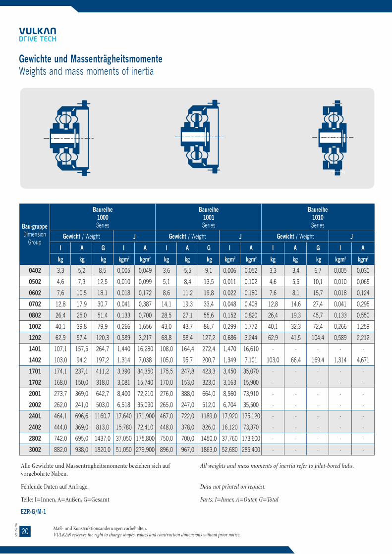
2120
EZR
2011
/04
EZR
2011
/04
Alle Gewichte und Massenträgheitsmomente beziehen sich aufvorgebohrte Naben.
Fehlende Daten auf Anfrage.
Teile: I=Innen, A=Außen, G=Gesamt
All weights and mass moments of inertia refer to pilot-bored hubs.
Data not printed on request.
Parts: I=Inner, A=Outer, G=Total
EZR-G/M-1
Bau-gruppeDimension
Group
Baureihe1000 Series
I A G GI A
kg
I
kgkg
A
kgkg kgm2 kgm2
Gewicht / Weight J
Gewichte und MassenträgheitsmomenteWeights and mass moments of inertia
Maß- und Konstruktionsänderungen vorbehalten.VULKAN reserves the right to change shapes, values and construction dimensions without prior notice..
0402
0502
0602
0702
0802
1002
1202
1401
1402
1701
1702
2001
2002
2401
2402
2802
3002
3,3
4,6
7,6
12,8
26,4
40,1
62,9
107,1
103,0
174,1
168,0
273,7
262,0
464,1
444,0
742,0
882,0
5,2
7,9
10,5
17,9
25,0
39,8
57,4
157,5
94,2
237,1
150,0
369,0
241,0
696,6
369,0
695,0
938,0
8,5
12,5
18,1
30,7
51,4
79,9
120,3
264,7
197,2
411,2
318,0
642,7
503,0
1160,7
813,0
1437,0
1820,0
0,005
0,010
0,018
0,041
0,133
0,266
0,589
1,440
1,314
3,390
3,081
8,400
6,518
17,640
15,780
37,050
51,050
0,049
0,099
0,172
0,387
0,700
1,656
3,217
16,280
7,038
34,350
15,740
72,210
35,090
171,900
72,410
175,800
279,900
3,6
5,1
8,6
14,1
28,5
43,0
68,8
108,0
105,0
175,5
170,0
276,0
265,0
467,0
448,0
750,0
896,0
5,5
8,4
11,2
19,3
27,1
43,7
58,4
164,4
95,7
247,8
153,0
388,0
247,0
722,0
378,0
700,0
967,0
9,1
13,5
19,8
33,4
55,6
86,7
127,2
272,4
200,7
423,3
323,0
664,0
512,0
1189,0
826,0
1450,0
1863,0
0,006
0,011
0,022
0,048
0,152
0,299
0,686
1,470
1,349
3,450
3,163
8,560
6,704
17,920
16,120
37,760
52,680
0,052
0,102
0,180
0,408
0,820
1,772
3,244
16,610
7,101
35,070
15,900
73,910
35,500
175,120
73,370
173,600
285,400
3,3
4,6
7,6
12,8
26,4
40,1
62,9
-
103,0
-
-
-
-
-
-
-
-
3,4
5,5
8,1
14,6
19,3
32,3
41,5
-
66,4
-
-
-
-
-
-
-
-
6,7
10,1
15,7
27,4
45,7
72,4
104,4
-
169,4
-
-
-
-
-
-
-
-
0,005
0,010
0,018
0,041
0,133
0,266
0,589
-
1,314
-
-
-
-
-
-
-
-
0,030
0,065
0,124
0,295
0,550
1,259
2,212
-
4,671
-
-
-
-
-
-
-
-
Baureihe1001Series
I I A
kg kg kgm2 kgm2
Gewicht / Weight J
GA
kg
Baureihe1010Series
I A
kg kgm2 kgm2
Gewicht / Weight J
Alle Gewichte und Massenträgheitsmomente beziehen sich aufvorgebohrte Naben.
Fehlende Daten auf Anfrage.
Teile: I=Innen, A=Außen, G=Gesamt
All weights and mass moments of inertia refer to pilot-bored hubs.
Data not printed on request.
Parts: I=Inner, A=Outer, G=Total
EZR-G/M-1
Bau-gruppeDimension
Group
Baureihe1011Series
I A G GI A
kg
I
kgkg
A
kgkg kgm2 kgm2
Gewicht / Weight J
Gewichte und MassenträgheitsmomenteWeights and mass moments of inertia
Maß- und Konstruktionsänderungen vorbehalten.VULKAN reserves the right to change shapes, values and construction dimensions without prior notice..
0402
0502
0602
0702
0802
1002
1202
1401
1402
3,6
5,1
8,6
14,1
28,5
43,0
68,8
-
105,0
3,7
6,0
8,8
16,0
21,3
35,8
46,1
-
74,0
7,3
11,1
17,4
30,1
49,8
78,8
114,9
-
179,0
0,006
0,011
0,022
0,048
0,152
0,299
0,686
-
1,349
0,032
0,069
0,132
0,316
0,596
1,366
2,403
-
5,080
3,3
4,6
7,6
12,8
26,4
40,1
62,9
-
103,0
6,6
10,5
13,0
25,2
34,9
52,0
75,3
-
117,0
9,9
15,1
20,6
38,0
61,3
92,1
138,2
-
220,0
0,005
0,010
0,018
0,041
0,133
0,266
0,589
-
1,314
0,074
0,158
0,241
0,708
1,266
2,441
4,956
-
9,757
3,6
5,1
8,6
14,1
28,5
43,0
68,8
-
105,0
6,9
11,1
13,7
26,6
36,9
55,5
79,9
-
124,0
10,5
16,2
22,3
40,7
65,4
98,5
148,7
-
229,0
0,006
0,011
0,022
0,048
0,152
0,299
0,686
-
1,349
0,076
0,163
0,249
0,729
1,312
2,548
5,147
-
10,170
Baureihe1020Series
I I A
kg kg kgm2 kgm2
Gewicht / Weight J
GA
kg
Baureihe1021Series
I A
kg kgm2 kgm2
Gewicht / Weight J

1922
EZR
2011
/04
EZR
2011
/04
Maße in mmDimensions in mm
1) Abmessungen auf Anfrage1) Dimensions on demand
EZR-A-1500-1
BaugruppeDimension Group
DurchmesserDiameter
LängenLengths
AbmessungenDimensions
Maß- und Konstruktionsänderungen vorbehalten.VULKAN reserves the right to change shapes, values and construction dimensions without prior notice..
A1 A2 A3 D1 D2 G1 S1 S2 T1 W1 W2 W3 Z1 Z3 H1 H4 K3 L6 R1 R3 V2
0402
0502
0602
0702
0802
1002
1202
1401
1402
1701
1702
2001
2002
2401
2402
2802
30021)
M 6
M 8
M 8
M12
M12
M14
M14
M16
M16
M20
M20
M24
M24
M27
M27
M27
M30
235
268
304
354
420
486
561
767
650
908
767
1051
908
1195
1051
1195
1315
252
290
330
380
445
514
593
808
690
958
808
1110
958
1262
1110
1262
1386
210
238
270
317
375
438
509
696
584
822
696
953
822
1087
953
1087
1194
113
135
156
205
230
271
298
358
358
420
420
540
540
630
630
750
850
99
118
134
170
198
230
264
322
322
378
378
480
480
565
565
680
750
10
11
15
15
15
17
17
26
22
32
26
35
32
35
35
35
38
8,5
10
13
15
20
20
22
22
22
26
26
33
33
33
33
33
48
12
12
12
12
12
16
16
16
16
16
16
16
16
16
16
16
24
60°
60°
60°
60°
60°
60°
60°
45°
45°
45°
45°
45°
45°
30°
30°
30°
30°
120°
120°
120°
120°
120°
120°
120°
90°
90°
90°
90°
90°
90°
60°
60°
60°
60°
30°
30°
30°
30°
30°
30°
30°
22°30‘
22°30‘
22°30‘
22°30‘
22°30‘
22°30‘
15°
15°
15°
15°
218
246
278
328
392
458
529
726
610
858
726
992
858
1128
992
1128
1244
85
101
116
144
172
200
234
287
287
334
334
420
420
500
500
610
650
8
10
12
14
14
16
18
25
23
28
25
32
28
34
32
34
40
18
21
26
27
34
38
44
54
54
60
60
56
51
74
55
60
85
22
25
28
39
50
55
69
69
77
81
86
88
57
76
69
58
61
102
115
134
162
199
226
263
324
310
372
347
416
339
510
396
478
535
3
3
3
3
4
4
5
6
5
8
6
8
8
8
8
8
10
4
5
6
6
7
7
7
8
8
8
8
10
10
10
10
13
15
14
14
16
16
21
24
27
45
30
60
33
70
41
98
46
76
75
Baureihe Series 1501mit Durchdrehsicherung
with torsional limit device
Der Anschlußflansch ist als Bohrschablone zu verwenden. The joining flange is to be used as a jig.
Baureihe Series 1500ohne Durchdrehsicherung
without torsional limit device
Lochteilung siehe W1, W2, W3,
For angular displacement of holes see W1, W2, W3,
Ab Baugr. 1002 S2 vorgebohrt für Zylinderstifte mit 80kp/mm2 Mindestzugfestigkeit.
From dimension group 1002 S2 pilot bored, for parallelpins with min. tensile strength of 80 kp/mm2
Ab Baugr. 2001 einteiligeFlanschnabe.
From dimension group2001 one-piece flange hub.
Alle Gewichte und Massenträgheitsmomente beziehen sich aufvorgebohrte Naben.
Fehlende Daten auf Anfrage.
Teile: I=Innen, A=Außen, G=Gesamt
All weights and mass moments of inertia refer to pilot-bored hubs.
Data not printed on request.
Parts: I=Inner, A=Outer, G=Total
EZR-G/M-1
Bau-gruppeDimension
Group
Baureihe1100 Series
I A G GI A
kg
I
kgkg
A
kgkg kgm2 kgm2
Gewicht / Weight J
Gewichte und MassenträgheitsmomenteWeights and mass moments of inertia
Maß- und Konstruktionsänderungen vorbehalten.VULKAN reserves the right to change shapes, values and construction dimensions without prior notice..
0402
0502
0602
0702
0802
1002
1202
1401
1402
1701
1702
2001
2002
2401
2402
2802
3002
3,3
4,6
7,6
12,8
26,4
40,1
62,9
107,1
103,0
174,1
168,0
273,7
262,0
464,1
444,0
742,0
882,0
7,3
9,8
15,4
21,9
30,3
48,5
69,8
212,2
114,0
328,3
205,0
529,2
332,0
962,0
529,0
961,0
1321,0
10,6
14,4
23,0
34,7
56,7
88,6
132,7
319,3
217,0
502,4
373,0
802,9
594,0
1426,0
973,0
1703,0
2203,0
0,005
0,010
0,018
0,041
0,133
0,266
0,589
1,440
1,314
3,390
3,081
8,400
6,518
17,640
15,780
37,050
51,050
0,049
0,099
0,172
0,387
0,700
1,656
3,217
16,280
7,038
34,350
15,740
72,210
35,090
171,900
72,410
175,800
279,900
3,6
5,1
8,6
14,1
28,5
43,0
68,8
108,0
105,0
175,5
170,0
276,0
265,0
467,0
448,0
750,0
896,0
3,6
5,1
8,6
14,1
28,5
43,0
68,8
108,0
105,0
175,5
170,0
276,0
265,0
467,0
448,0
750,0
896,0
7,7
10,4
16,1
23,3
32,4
52,1
73,0
219,1
115,0
338,8
208,0
548,2
338,0
988,0
538,0
966,0
1350,0
11,3
15,5
24,7
37,4
60,9
95,1
141,8
327,1
220,0
514,3
378,0
824,2
603,0
1455,0
986,0
1716,0
2246,0
0,006
0,011
0,022
0,048
0,152
0,299
0,686
1,470
1,349
3,450
3,163
8,560
6,704
17,920
16,120
37,760
52,680
0,081
0,153
0,290
0,529
1,043
2,252
4,288
24,730
9,030
53,970
23,980
118,450
54,370
270,480
118,000
269,000
452,000
3,3
4,6
7,6
12,8
26,4
40,1
62,9
-
-
-
-
-
-
-
-
-
-
9,5
12,3
24,1
31,8
42,8
68,0
93,3
-
-
-
-
-
-
-
-
-
-
12,8
16,9
31,7
44,6
69,2
108,1
156,2
-
-
-
-
-
-
-
-
-
-
0,123
0,215
0,639
1,020
1,819
3,893
6,754
-
-
-
-
-
-
-
-
-
-
Baureihe1101Series
I I A
kg kg kgm2 kgm2
Gewicht / Weight J
GA
kg
Baureihe1110Series
I A
kg kgm2 kgm2
Gewicht / Weight J

2318
EZR
2011
/04
EZR
2011
/04
Maße in mmDimensions in mm
1) EZR 3022 nicht in dieser Baureihe lieferbar1) EZR 3022 not available in this series
EZR-A-1400-1
BaugruppeDimension Group
vorgebohrtPilot bored
vorgebohrtPilot bored
DurchmesserDiameter
LängenLengths
AbmessungenDimensions
Maß- und Konstruktionsänderungen vorbehalten.VULKAN reserves the right to change shapes, values and construction dimensions without prior notice..
B1 B1 max. B2 B2 max. A1 A2 F1 F2 K1 L1 L3 L5 N1 N2
0402
0502
0602
0702
0802
1002
1202
1401
1402
1701
1702
2001
2002
2401
2402
2802
30021)
20
25
30
40
50
60
70
80
80
95
95
115
115
135
135
175
225
50
55
65
75
100
120
135
160
160
190
190
230
230
280
280
310
330
25
30
40
50
60
70
80
95
95
115
115
135
135
175
175
225
245
58
70
80
110
130
150
170
205
205
245
245
290
290
330
330
355
380
252
290
330
380
445
514
593
808
690
958
808
1110
958
1262
1110
1262
1386
210
238
270
317
375
438
509
696
584
822
696
953
822
1087
953
1087
1194
1
1
1
1,5
1,5
2
2
3
3
3
3
4
4
4
4
4
4
1
1
1,5
1,5
2
2
3
3
3
3
3
4
4
4
4
4
4
21
23
26
36
47
52
66
67
75
77
82
88
100
80
116
116
131
90
101
119
146
175
200
237
268
278
308
283
360
331
440
388
476
520
117
128
157
178
208
242
285
334
331
385
349
460
408
569
488
605
680
176
196
243
285
332
387
455
524
521
608
572
727
675
904
823
957
1147
62
69
80
103
126
143
168
199
199
222
222
258
258
302
302
358
400
62
71
90
111
129
150
175
196
196
229
229
272
272
340
340
358
475
Baureihe Series 1401mitDurchdrehsicherung
with torsional limit device
Baureihe Series 1400ohne Durchdrehsicherung
without torsional limit device
Ab Baugr. 1002 VerbindungNabe, Tellerflansch durch Zylinder-stifte
From dimension group 1002connection hub-plate flange by parallel pins
Alle Gewichte und Massenträgheitsmomente beziehen sich aufvorgebohrte Naben.
Fehlende Daten auf Anfrage.
Teile: I=Innen, A=Außen, G=Gesamt
All weights and mass moments of inertia refer to pilot-bored hubs.
Data not printed on request.
Parts: I=Inner, A=Outer, G=Total
EZR-G/M-1
Bau-gruppeDimension
Group
Baureihe1111 Series
I A G GI A
kg
I
kgkg
A
kgkg kgm2 kgm2
Gewicht / Weight J
Gewichte und MassenträgheitsmomenteWeights and mass moments of inertia
Maß- und Konstruktionsänderungen vorbehalten.VULKAN reserves the right to change shapes, values and construction dimensions without prior notice..
0402
0502
0602
0702
0802
1002
1202
1401
1402
1701
1702
2001
2002
2401
2402
2802
3002
3,6
5,1
8,6
14,1
28,5
43,0
68,8
-
-
-
-
-
-
-
-
-
-
9,7
12,7
24,8
33,2
44,9
71,6
96,5
-
-
-
-
-
-
-
-
-
-
13,3
17,8
33,4
47,3
73,4
114,6
165,3
-
-
-
-
-
-
-
-
-
-
0,006
0,011
0,022
0,048
0,152
0,299
0,686
-
-
-
-
-
-
-
-
-
-
0,122
0,213
0,647
1,040
1,865
4,000
6,900
-
-
-
-
-
-
-
-
-
-
3,3
4,6
7,6
12,8
26,4
40,1
62,9
107,1
103,0
174,1
168,0
273,7
262,0
464,0
444,0
742,0
882,0
9,8
13,4
21,6
32,3
45,0
72,6
110,0
271,1
172,0
416,7
264,0
659,0
421,0
1173,0
704,0
1185,0
1598,0
13,1
18,0
29,2
45,1
71,4
112,7
172,9
378,2
276,0
590,8
432,0
932,7
683,0
1637,0
1148,0
1927,0
2480,0
0,005
0,010
0,018
0,041
0,133
0,266
0,589
1,440
1,314
3,390
3,081
8,400
6,518
17,640
15,780
37,050
51,050
0,097
0,186
0,367
0,691
1,392
3,001
6,085
27,850
12,910
60,490
27,590
131,810
62,060
299,600
140,200
307,300
495,600
3,6
5,1
8,6
14,1
28,5
43,0
68,8
108,0
105,0
175,5
170,0
276,0
265,0
467,0
448,0
750,0
896,0
10,1
13,9
22,3
33,7
47,1
76,2
114,0
278,0
174,0
427,5
267,0
678,0
427,0
1199,0
713,0
1190,0
1627,00
13,7
19,0
30,9
47,8
75,6
119,2
182,8
386,0
279,0
602,9
437,0
954,0
692,0
1666,0
1161,0
1940,0
2523,0
0,006
0,011
0,022
0,048
0,152
0,299
0,686
1,470
1,349
3,450
3,163
8,560
6,704
17,920
16,120
37,760
52,680
0,100
0,189
0,375
0,711
1,438
3,107
6,232
28,180
12,980
61,210
27,730
133,510
62,480
302,820
141,100
308,000
501,200
Baureihe1200Series
I I A
kg kg kgm2 kgm2
Gewicht / Weight J
GA
kg
Baureihe1201Series
I A
kg kgm2 kgm2
Gewicht / Weight J

1724
EZR
2011
/04
EZR
2011
/04
Maße in mmDimensions in mm
EZR-A-1300-1
BaugruppeDimension Group
vorgebohrtPilot bored
DurchmesserDiameter
LängenLengths
AbmessungenDimensions
Maß- und Konstruktionsänderungen vorbehalten.VULKAN reserves the right to change shapes, values and construction dimensions without prior notice..
B1 B1 max. A1 A2 D1 S1 T1 Z1 F2 H1 K2 L4 N2 R1 V2
0402
0502
0602
0702
0802
1002
1202
1401
1402
1701
1702
2001
2002
2401
2402
2802
30021)
25
30
40
50
60
70
80
95
95
115
115
135
135
175
175
225
245
58
70
80
110
130
150
170
205
205
245
245
290
290
330
330
355
380
252
290
330
380
445
514
593
808
690
958
808
1110
958
1262
1110
1262
1386
210
238
270
317
375
438
509
696
584
822
696
953
822
1087
953
1087
1194
235
268
304
354
420
486
561
767
650
908
767
1051
908
1195
1051
1195
1315
10
11
15
15
15
17
17
26
22
32
26
35
32
35
35
35
38
12
12
12
12
16
16
16
16
16
16
16
16
16
16
16
16
24
218
246
278
328
392
458
529
726
610
858
726
992
858
1128
992
1128
1244
1
1
1
1,5
1,5
2
2
3
3
3
3
4
4
4
4
4
4
8
10
12
14
14
16
18
25
23
28
25
32
28
34
32
34
40
22
25
28
39
50
55
69
69
77
81
86
88
57
76
69
58
61
161
183
220
269
323
371
433
514
500
595
570
683
606
845
731
830
1002
62
71
90
111
129
150
175
196
196
229
229
272
272
340
340
358
475
3
3
3
3
4
4
5
6
5
8
6
8
8
8
8
8
10
14
14
16
16
21
24
27
45
30
60
33
70
41
98
46
76
75
Baureihe Series 1301mit Durchdrehsicherung
with torsional limit device
Baureihe Series 1300ohne Durchdrehsicherung
without torsional limit device
Ab Baugr. 2002 einteilige Flanschnabe.
From dimension group 2002 on one-piece flanged hub.
Längen-Ausgleichsring
Length-compensating ring
Ab Baugr. 2001 Verbindung durch Zylin-derstifte.
From dimension group 2001 on, connection by parallel pins.
Alle Gewichte und Massenträgheitsmomente beziehen sich aufvorgebohrte Naben.
Fehlende Daten auf Anfrage.
Teile: I=Innen, A=Außen, G=Gesamt
All weights and mass moments of inertia refer to pilot-bored hubs.
Data not printed on request.
Parts: I=Inner, A=Outer, G=Total
EZR-G/M-1
Bau-gruppeDimension
Group
Baureihe1300Series
I A G GI A
kg
I
kgkg
A
kgkg kgm2 kgm2
Gewicht / Weight J
Gewichte und MassenträgheitsmomenteWeights and mass moments of inertia
Maß- und Konstruktionsänderungen vorbehalten.VULKAN reserves the right to change shapes, values and construction dimensions without prior notice..
0402
0502
0602
0702
0802
1002
1202
1401
1402
1701
1702
2001
2002
2401
2402
2802
3002
6,4
10,0
16,3
31,8
53,6
82,2
123,0
214,5
210,0
337,8
329,0
549,9
495,0
929,0
833,0
1194,0
1850,0
5,2
7,9
10,5
17,9
25,0
39,8
57,4
157,5
94,2
237,1
150,0
369,0
241,0
696,6
369,0
695,0
938,0
11,6
17,9
26,8
49,7
78,6
122,0
180,4
372,0
304,2
574,9
482,0
918,9
736,0
1625,6
1202,0
1889,0
2788,0
0,011
0,023
0,045
0,138
0,322
0,661
1,289
3,170
3,039
7,070
6,764
18,320
15,020
40,720
35,110
71,890
133,000
0,049
0,099
0,172
0,387
0,700
1,656
3,217
16,280
7,038
34,350
15,740
72,210
35,090
171,900
72,410
175,800
279,900
6,7
10,5
17,1
33,1
55,8
85,1
129,0
215,4
211,0
339,2
331,0
552,3
506,0
932,0
846,0
1216,0
1887,0
5,5
8,4
11,2
19,3
27,1
43,7
58,4
164,4
95,7
247,8
153,0
388,0
247,0
722,0
378,0
700,0
967,0
12,2
18,9
28,3
52,4
82,9
128,8
187,4
379,8
306,7
587,0
482,0
940,3
753,0
1654,0
1224,0
1916,0
2854,0
0,012
0,025
0,048
0,145
0,341
0,694
1,387
3,200
3,053
7,140
6,766
18,480
15,820
41,000
36,180
74,240
137,800
0,052
0,102
0,180
0,408
0,820
1,772
3,244
16,610
7,101
35,070
15,900
73,910
35,500
175,120
73,370
173,600
285,400
3,3
4,6
7,6
12,8
26,4
40,1
62,9
107,1
103,0
174,1
168,0
273,6
262,0
464,0
444,0
742,0
882,0
12,4
17,7
28,5
47,4
68,9
109,0
166,0
361,6
262,0
558,5
406,0
917,4
672,0
1604,8
1127,0
1723,0
2548,0
15,7
22,3
36,1
60,2
95,3
149,1
228,9
468,7
365,0
732,6
574,0
1191,0
934,0
2068,8
1571,0
2465,0
3430,0
0,005
0,010
0,018
0,041
0,133
0,266
0,589
1,440
1,314
3,390
3,081
8,400
6,518
17,640
15,780
37,780
51,050
0,100
0,194
0,382
0,748
1,513
3,250
6,562
28,970
14,030
62,910
30,010
138,750
68,580
315,630
155,500
335,000
556,000
Baureihe1301Series
I I A
kg kg kgm2 kgm2
Gewicht / Weight J
GA
kg
Baureihe1400Series
I A
kg kgm2 kgm2
Gewicht / Weight J

2516
EZR
2011
/04
EZR
2011
/04
Maße in mmDimensions in mm
1) EZR 3022 nicht in dieser Baureihe lieferbar1) EZR 3022 not available in this series
EZR-A-1200-1
BaugruppeDimension Group
vorgebohrtPilot bored
DurchmesserDiameter
LängenLengths
AbmessungenDimensions
Maß- und Konstruktionsänderungen vorbehalten.VULKAN reserves the right to change shapes, values and construction dimensions without prior notice..
B1 B1 max. A1 A2 A3 D2 G1 S2 W1 W2 W3 Z3 F1 F3 H3 K1 L1 L3 N1
0402
0502
0602
0702
0802
1002
1202
1401
1402
1701
1702
2001
2002
2401
2402
2802
30021)
20
25
30
40
50
60
70
80
80
95
95
115
115
135
135
175
225
50
55
65
75
100
120
135
160
160
190
190
230
230
280
280
310
330
252
290
330
380
445
514
593
808
690
958
808
1110
958
1262
1110
1262
1386
210
238
270
317
375
438
509
696
584
822
696
953
822
1087
953
1087
1194
113
135
156
205
230
271
298
358
358
420
420
540
540
630
630
750
850
99
118
134
170
198
230
264
322
322
378
378
480
480
565
565
680
750
M 6
M 8
M 8
M12
M12
M14
M14
M16
M16
M20
M20
M24
M24
M27
M27
M27
M30
8,5
10
13
15
20
20
22
22
22
26
26
33
33
33
33
33
48
60°
60°
60°
60°
60°
60°
60°
45°
45°
45°
45°
45°
45°
30°
30°
30°
30°
120°
120°
120°
120°
120°
120°
120°
90°
90°
90°
90°
90°
90°
60°
60°
60°
60°
30°
30°
30°
30°
30°
30°
30°
22°30‘
22°30‘
22°30‘
22°30‘
22°30‘
22°30‘
15°
15°
15°
15°
85
101
116
144
172
200
234
287
287
334
334
420
420
500
500
610
650
1
1
1
1,5
1,5
2
2
3
3
3
3
4
4
4
4
4
4
0,5
0,5
1
1
1
1
1
1,5
1,5
2
2
2
2
2
2
3
3
10
12
17
19
18
23
29
30
30
32
32
35
35
50
50
55
60
21
23
26
36
47
52
66
67
75
77
82
88
100
80
116
116
131
90
101
119
146
175
200
237
268
278
308
283
360
331
440
388
476
520
117
128
157
178
208
242
285
334
331
385
349
460
408
569
488
605
680
62
69
80
103
126
143
168
199
199
222
222
258
258
302
302
358
400
Baureihe Series 1201mit Durchdrehsicherung
with torsional limit device
Ab Baugr. 1002 S2 vorgebohrtfür Zylinderstifte mit 80 kp/m2
Mindestzugfestigkeit.
From dimension group 1002 S2
pilot bored, for parallel pins withmin. tensile strength of 80 kp/mm2
Lochteilung siehe W1, W2, W3.
For angular displacement of holessee W1, W2, W3.
Der Tellerflansch ist als Bohrschablone zu verwenden. The plate flange is to be used as a jig.
Baureihe Series 1200ohne Durchdrehsicherung
without torsional limit device
Alle Gewichte und Massenträgheitsmomente beziehen sich aufvorgebohrte Naben.
Fehlende Daten auf Anfrage.
Teile: I=Innen, A=Außen, G=Gesamt
All weights and mass moments of inertia refer to pilot-bored hubs.
Data not printed on request.
Parts: I=Inner, A=Outer, G=Total
EZR-G/M-1
Bau-gruppeDimension
Group
Baureihe1401Series
I A G GI A
kg
I
kgkg
A
kgkg kgm2 kgm2
Gewicht / Weight J
Gewichte und MassenträgheitsmomenteWeights and mass moments of inertia
Maß- und Konstruktionsänderungen vorbehalten.VULKAN reserves the right to change shapes, values and construction dimensions without prior notice..
0402
0502
0602
0702
0802
1002
1202
1401
1402
1701
1702
2001
2002
2401
2402
2802
3002
3,6
5,1
8,6
14,1
28,5
43,0
68,8
108,0
105,0
175,5
170,0
276,0
265,0
467,0
448,0
750,0
896,0
12,8
18,2
29,2
48,8
70,9
113,0
169,0
368,4
264,0
569,2
409,0
936,4
685,0
1631,0
1144,0
1742,0
2599,0
16,4
23,3
37,8
62,9
99,4
156,0
237,8
476,4
369,0
744,7
579,0
1212,4
950,0
2098,0
1592,0
2492,0
3495,0
0,006
0,011
0,022
0,048
0,152
0,299
0,686
1,470
1,349
3,450
3,163
8,560
6,701
17,920
16,120
37,760
52,680
0,103
0,196
0,391
0,769
1,559
3,356
6,709
29,300
14,100
63,630
30,150
140,450
69,410
318,850
157,100
337,400
565,000
3,8
5,6
9,4
16,7
29,7
45,8
67,8
124,0
120,0
196,0
190,0
291,5
244,0
497,1
410,0
656,0
900,0
5,2
7,9
10,5
17,9
25,0
39,8
57,4
157,5
94,2
237,1
150,0
369,0
241,0
696,6
369,0
695,0
938,0
9,0
13,5
19,9
34,6
54,7
85,6
125,2
281,5
214,2
433,1
340,0
660,5
485,0
1193,7
779,0
1351,0
1838,0
0,007
0,015
0,030
0,081
0,201
0,412
0,812
2,040
1,917
4,650
4,342
11,380
8,502
24,690
19,800
44,170
72,340
0,049
0,099
0,172
0,387
0,700
1,656
3,217
16,280
7,038
34,350
15,740
72,210
35,090
171,900
72,410
175,800
279,900
4,1
6,2
10,1
18,0
31,9
48,7
73,8
125,0
122,0
197,4
192,0
293,8
248,0
500,0
414,0
664,0
915,0
5,5
8,4
11,2
19,3
27,1
43,7
58,4
164,4
95,7
247,8
153,0
388,0
247,0
722,0
378,0
700,0
967,0
9,6
14,6
21,3
37,3
59,0
92,4
132,2
289,4
217,7
445,2
345,0
681,8
495,0
1222,0
792,0
1364,0
1882,0
0,008
0,017
0,033
0,088
0,220
0,445
0,909
2,080
1,952
4,720
4,424
11,540
8,688
24,970
20,130
44,870
73,970
0,052
0,102
0,180
0,408
0,820
1,772
3,244
16,610
7,101
35,070
15,900
73,910
35,500
175,120
73,370
173,600
285,400
Baureihe1500Series
I I A
kg kg kgm2 kgm2
Gewicht / Weight J
GA
kg
Baureihe1501Series
I A
kg kgm2 kgm2
Gewicht / Weight J

1526
EZR
2011
/04
EZR
2011
/04
Maße in mmDimensions in mm
EZR-A-1110-0
BaugruppeDimension Group
vorgebohrtPilot bored
DurchmesserDiameter
LängenLengths
AbmessungenDimensions
Maß- und Konstruktionsänderungen vorbehalten.VULKAN reserves the right to change shapes, values and construction dimensions without prior notice..
B1 B1 max. A2 D3 S3 T2 Z4 F1 H5 K1 L2 N1 R2 V1
0402
0502
0602
0702
0802
1002
1202
20
25
30
40
50
60
70
Baureihe Series 1110 ohne Durchdrehsicherung
without torsional limit device
Baureihe Series 1111mit Durchdrehsicherungwith torsional limit device
50
55
65
75
100
120
135
210
238
270
317
375
438
135
295,3
333,4
438,2
489,0
542,9
641,4
692,2
11
11
14
14
17
17
20
8
8
8
8
6
12
12
314,3
352,4
466,7
517,5
571,5
673,1
733,4
1
1
1
1,5
1,5
2
2
10
10
14
14
17
18
22
21
23
26
36
47
52
66
110
119
143
162
193
223
261
62
69
80
103
126
143
168
3
3
3
3
4
4
5
38
38
50
43
48
58
67
MontagevorschriftenAssembly Instruction
Maß- und Konstruktionsänderungen vorbehalten.VULKAN reserves the right to change shapes, values and construction dimensions without prior notice..
1000 und 10011000 and 1001
1010/01 und /021010/01 and /02
1020 und 10211020 and 1021
1100 und 11011100 and 1101
1110 und 11111110 and 1111
Jede hochelastische VULKAN-EZR Kupplung verläßt montiert das Werkund braucht für den Einbau in die Antriebsanlage nicht auseinander genom-men zu werden.
Vor dem Einbau in die Anlage ist das Montage-Kontrollmaß derKupplung zu überprüfen. Durch falschen Transport oder falscheLagerung der EZR Kupplung kann es vorkommen, daß das Montage-Kontrollmaß kleiner geworden ist. Dies bedeutet, daß das Innenteil aufdem Außenteil oder umgekehrt gelegen hat und die EZR Elemente einerelastischen Verformung ausgesetzt waren.
In der Regel ist eine elastische Lagerung in der Schubrichtung, d. h. inRichtung der Kurbelwelle und damit in Richtung der Kupplung, sehrweich. Will man jetzt das zu kleine Montage-Kontrollmaß im eingebautenZustand korrigieren, verzieht man meistens die elastisch gelagerte Masseund verspannt damit die elastischen Elemente. Hierdurch entstehenerhöhte Vibrationsbe-wegungen beim Anfahren sowie unter Umständen zuhohe Axial-belastungen der maschinenseitigen Führungslager.
Das Montage-Kontrollmaß muß also vor dem Einbau der hoche-lastis-chen VULKAN-EZR Kupplung auf das vorgeschriebene Maß gebrachtwerden: den Flanschmantel der Kupplung festhalten und mit einem Hebezeugdie Nabe auf das vorgeschriebene Montage-Kontrollmaß mehrmals anspannen.
Sollte sich das Montage-Kontrollmaß durch falschen Transport oder falscheLagerung vergrößert haben, so ist eine Korrektur in umgekehrter Reihenfolgevorzunehmen.
Bei starr aufgestellten Maschinen ist eine Korrektur des Montage-Kontrollmaßesvor dem Einbau in den meisten Fällen nicht erfor-derlich.Die nach der Montage der Kupplung wirkende Axialkraft Fa hebt sich nachdem Anlaufen der Maschine wieder auf.
Alle Schraubenverbindungen bei der Montage der Kupplung mit den zuverbindenden Maschinen sollten mit einem Drehmomenschlüssel angezo-gen werden. Die entsprechenden Schraubenan-zugsmomente sind derTabelle 1 zu entnehmen.
Every highly flexible VULKAN-EZR coupling leaves our works in the assembledcondition and does not need to be disassembled for installation into thedrive system.
Before installation into the system the „alignment control“ dimension of thecoupling must be checked. Due to transportation or incorrect storage of theEZR coupling it may happen that the „alignment control“ dimension hasdiminished. This signifies that the inner and outer parts were not correctlysupported and that the EZR elements have undergone a flexible deformation.
Normally flexible mountings are very soft in the thrust direction, i. e. in directionof the crankshaft and thus in direction of the coupling. If it is intended to correctthe „alignment control“ dimension which is too small in the assembled conditionit will often distort the flexibly mounted mass and thus deform the flexibleelements. This results in higher vibratory movements when starting-up and,in certain circumstances, in exessively high axial loads on the engine crank-shaft end bearing.
It is thus necessary that the „alignment control“ dimension is resto-red to theprescribed dimension before installing the highly flexible VULKAN-EZR coupling.To do this solidly fix the flanged casing and by means of a jack or crane pushor pull the hub outwards several times until the prescribed „alignment control“dimension is attained.
If the „alignment control“ dimension has increased due to transport or incorrectstoring one proceeds with this correction in the reverse manner.
With rigidly mounted engines it is not necessary in most cases to correct the„alignment control“ dimension before installation.The resulting axial force Fa after installation of the coupling will be compensatedfor after starting-up the machinery.
All bolted connections should be tightened using a torque spanner wheninstalling the coupling with its connected machines. The respec-tive tighteningtorques are listed in table 1.
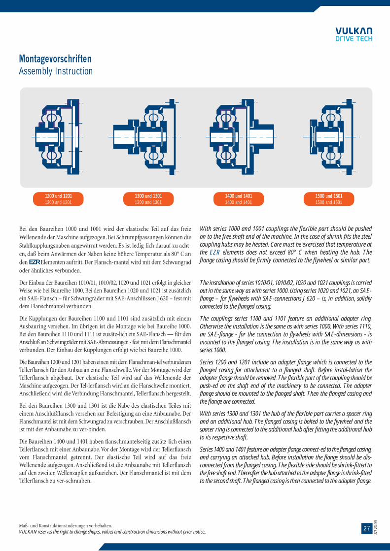
2714
EZR
2011
/04
EZR
2011
/04
Maße in mmDimensions in mm
1) EZR 3022 nicht in dieser Baureihe lieferbar1) EZR 3022 not available in this series
EZR-A-1100-1
BaugruppeDimension Group
vorgebohrtPilot bored
DurchmesserDiameter
LängenLengths
AbmessungenDimensions
Maß- und Konstruktionsänderungen vorbehalten.VULKAN reserves the right to change shapes, values and construction dimensions without prior notice..
B1 B1 max. A2 D1 S1 T1 Z2 F1 H1 H2 K1 L1 L2 N1 R2 V1
0402
0502
0602
0702
0802
1002
1202
1401
1402
1701
1702
2001
2002
2401
2402
2802
30021)
20
25
30
40
50
60
70
80
80
95
95
115
115
135
135
175
225
50
55
65
75
100
120
135
160
160
190
190
230
230
280
280
310
330
Baureihe Series 1100ohne Durchdrehsicherung
without torsional limit device
Baureihe Series 1101mit Durchdrehsicherungwith torsional limit device
235
268
304
354
420
486
561
767
650
908
767
1051
908
1195
1051
1195
1315
10
11
15
15
15
17
17
26
22
32
26
35
32
35
35
35
38
12
12
12
12
12
16
16
16
16
16
16
16
16
16
16
16
24
252
290
330
380
445
514
593
810
690
960
810
1112
960
1264
1112
1264
1388
1
1
1
1,5
1,5
2
2
3
3
3
3
4
4
4
4
4
4
20
18
24
16
18
23
24
66
26
77
66
100
77
129
100
129
160
8
10
12
14
14
16
18
25
23
28
25
32
28
34
32
34
40
21
23
26
36
47
52
66
67
75
77
82
88
100
80
116
116
131
90
101
119
146
175
200
237
268
278
308
283
360
331
440
388
476
520
110
119
143
162
193
223
261
334
304
385
349
460
408
569
488
605
680
62
69
80
103
126
143
168
199
199
222
222
258
258
302
302
358
400
3
3
3
3
4
4
5
6
5
8
6
8
8
8
8
8
10
38
38
50
43
48
58
67
105
75
129
93
162
110
219
138
197
225
MontagevorschriftenAssembly Instruction
Maß- und Konstruktionsänderungen vorbehalten.VULKAN reserves the right to change shapes, values and construction dimensions without prior notice..
1200 und 12011200 and 1201
1300 und 13011300 and 1301
1400 und 14011400 and 1401
1500 und 15011500 and 1501
Bei den Baureihen 1000 und 1001 wird der elastische Teil auf das freieWellenende der Maschine aufgezogen. Bei Schrumpfpassungen können dieStahlkupplungsnaben angewärmt werden. Es ist ledig-lich darauf zu acht-en, daß beim Anwärmen der Naben keine höhere Temperatur als 80° C anden EZR Elementen auftritt. Der Flansch-mantel wird mit dem Schwungradoder ähnliches verbunden.
Der Einbau der Baureihen 1010/01, 1010/02, 1020 und 1021 erfolgt in gleicherWeise wie bei Baureihe 1000. Bei den Baureihen 1020 und 1021 ist zusätzlichein SAE-Flansch – für Schwungräder mit SAE-Anschlüssen J 620 – fest mitdem Flanschmantel verbunden.
Die Kupplungen der Baureihen 1100 und 1101 sind zusätzlich mit einemAusbauring versehen. Im übrigen ist die Montage wie bei Baureihe 1000.Bei den Baureihen 1110 und 1111 ist zusätz-lich ein SAE-Flansch — für denAnschluß an Schwungräder mit SAE-Abmessungen - fest mit dem Flanschmantelverbunden. Der Einbau der Kupplungen erfolgt wie bei Baureihe 1000.
Die Baureihen 1200 und 1201 haben einen mit dem Flanschman-tel verbundenenTellerflansch für den Anbau an eine Flanschwelle.Vor der Montage wird derTellerflansch abgebaut. Der elastische Teil wird auf das Wellenende derMaschine aufgezogen. Der Tel-lerflansch wird an die Flanschwelle montiert.Anschließend wird die Verbindung Flanschmantel, Tellerflansch hergestellt.
Bei den Baureihen 1300 und 1301 ist die Nabe des elastischen Teiles miteinem Anschlußflansch versehen zur Befestigung an eine Anbaunabe. DerFlanschmantel ist mit dem Schwungrad zu verschrauben.Der Anschlußflanschist mit der Anbaunabe zu ver-binden.
Die Baureihen 1400 und 1401 haben flanschmantelseitig zusätz-lich einenTellerflansch mit einer Anbaunabe.Vor der Montage wird der Tellerflanschvom Flanschmantel getrennt. Der elastische Teil wird auf das freieWellenende aufgezogen. Anschließend ist die Anbaunabe mit Tellerflanschauf den zweiten Wellenzapfen aufzuziehen. Der Flanschmantel ist mit demTellerflansch zu ver-schrauben.
With series 1000 and 1001 couplings the flexible part should be pushedon to the free shaft end of the machine. In the case of shrink fits the steelcoupling hubs may be heated. Care must be exercised that temperature atthe EZR elements does not exceed 80° C when heating the hub. Theflange casing should be firmly connected to the flywheel or similar part.
The installation of series 1010/01, 1010/02, 1020 and 1021 couplings is carriedout in the same way as with series 1000. Using series 1020 and 1021, an SAE-flange – for flywheels with SAE-connections J 620 – is, in addition, solidlyconnected to the flanged casing.
The couplings series 1100 and 1101 feature an additional adapter ring.Otherwise the installation is the same as with series 1000. With series 1110,an SAE-flange - for the connection to flywheels with SAE-dimensions - ismounted to the flanged casing. The installation is in the same way as withseries 1000.
Series 1200 and 1201 include an adapter flange which is connected to theflanged casing for attachment to a flanged shaft. Before instal-lation theadapter flange should be removed. The flexible part of the coupling should bepush-ed on the shaft end of the machinery to be connected. The adapterflange should be mounted to the flanged shaft. Then the flanged casing andthe flange are connected.
With series 1300 and 1301 the hub of the flexible part carries a spacer ringand an additional hub. The flanged casing is bolted to the flywheel and thespacer ring is connected to the additional hub after fitting the additional hubto its respective shaft.
Series 1400 and 1401 feature an adapter flange connect-ed to the flanged casing,and carrying an attached hub. Before installation the flange should be dis-connected from the flanged casing. The flexible side should be shrink-fitted tothe free shaft end. Thereafter the hub attached to the adapter flange is shrink-fittedto the second shaft. The flanged casing is then connected to the adapter flange.

1328
EZR
2011
/04
EZR
2011
/04
Maße in mmDimensions in mm
1) Abmessungen auf Anfrage1) Dimensions on demand
EZR-A-1020-1
BaugruppeDimension Group
vorgebohrtPilot bored
DurchmesserDiameter
LängenLengths
AbmessungenDimensions
Maß- und Konstruktionsänderungen vorbehalten.VULKAN reserves the right to change shapes, values and construction dimensions without prior notice..
B1 B1 max. D3 S3 T2 Z4 F1 H5 K5 L13 L16 L18 N1 J620
0402
0502
0602
0702
0802
1002
1202
14011)
1402
20
25
30
40
50
60
70
80
Baureihe Series 1020ohne Durchdrehsicherung
without torsional limit device
Baureihe Series 1021mit Durchdrehsicherungwith torsional limit device
50
55
65
75
100
120
135
160
244,5
295,3
333,4
438,2
489,0
542,9
641,4
692,2
11
11
11
14
14
17
17
20
6
8
8
8
8
6
12
12
263,5
314,3
352,4
466,7
517,5
571,5
673,1
733,4
1
1
1
1,5
1,5
2
2
2
17
17
15
15
15
16
18
23
43
48
52
72
86
98
114
133
4,5
4,5
4,5
4,5
6,3
8,0
9,2
10,6
68
75
79
101
130
149
179
217
4
6
14
18
15
16
15
12
62
69
80
103
126
143
168
199
8
10
111/2
14
16
18
21
24
MontagevorschriftenAssembly Instruction
Maß- und Konstruktionsänderungen vorbehalten.VULKAN reserves the right to change shapes, values and construction dimensions without prior notice..
Die Naben der Baureihen 1500 und 1501 sind zusätzlich mit einem Anschlußflanschausgerüstet. Die Kupplung ist fest mit dem Schwungrad zu verschrauben.Die Flanschwelle ist mit dem Anschlußflansch zu verbinden.
Ausführliche Einbau- und Wartungsvorschriften für alle Baureihen werdenauf Wunsch zur Verfügung gestellt.
Nach der Montage der Kupplung ist die Ausrichtung der Anlage zu überprüfen(s. Abschnitt „Ausrichthinweise“ Seite 35-39).
SicherheitsvorkehrungenAlle Kupplungen sind gemäß den Unfallverhütungsvorschriften abzudecken.Die Abdeckungen sind, wenn keine anderen überge-ordneten Gesichtspunktedagegensprechen, in Lochblechen oder Streckmetallen auszuführen, um gle-ichzeitig eine gute Belüftung der Kupplung zu gewährleisten.
The hub of series 1500 and 1501 carries spacer rings. The coupling shouldbe tightly bolted to the flywheel, and the flanged shaft should be con-nected to the spacer ring.
Detailed installation and maintenance instructions for all series willbe supplied on demand.
After installation of the coupling one has to check the alignment of thesystem (see section „Alignment Instructions“ page 35-39).
Safety PrecautionsAll couplings have to be shielded according to safety regulations.These shields have to be constructed using perforated sheet or wire meshto guarantee adequate ventilation, when it is not in contradiction withother and prevailing requirements.

2912
EZR
2011
/04
EZR
2011
/04
Maße in mmDimensions in mm
1) Abmessungen auf Anfrage1) Dimensions on demand
EZR-A-1010-1
BaugruppeDimension Group
vorgebohrtPilot bored
DurchmesserDiameter
Baureihe/Series 1010/01 und/and 1011/01
Baureihe/Series 1010/02 und/and 1011/02
LängenLengths
AbmessungenDimensions
Maß- und Konstruktionsänderungen vorbehalten.VULKAN reserves the right to change shapes, values and construction dimensions without prior notice..
B1 B1 max. A3 D6 S5 T5 Z7 K5 H9 F1 K6 L11 L12 L13 L14 L15 N1 R6
0402
0502
0602
0702
0802
1002
1202
1401
1402
0402
0502
0602
0702
0802
10011)
1002
12011)
1202
14011)
1402
20
25
30
40
50
60
70
80
20
25
30
40
50
60
70
80
50
55
65
75
100
120
135
160
50
55
65
75
100
120
135
160
236
272
311
360
416
490
565
648
236
272
311
360
416
490
565
648
218
250
286
335
390
458
530
608
218
250
286
335
390
458
530
608
10
11
15
15
15
17
17
22
10
11
15
15
15
17
17
22
12
12
12
12
12
16
16
16
12
12
12
12
12
16
16
16
198
226
259
308
364
426
495
566
198
226
259
308
364
426
495
566
1
1
1
1,5
1,5
2
2
3
1
1
1
1,5
1,5
2
2
3
8
10
12
14
14
16
18
23
8
10
12
14
14
16
18
23
43
48
52
72
86
98
114
133
29
33
41
48
62
70
84
98
51
58
64
86
100
114
132
156
21
23
29
33
45
51
62
73
4,5
4,5
4,5
4,5
6,3
8
9,2
10,6
4,5
4,5
4,5
4,5
6,3
8
9,2
10,6
37
43
53
62
76
86
102
121
35
38
40
57
69
79
92
108
62
69
80
103
126
143
168
199
62
69
80
103
126
143
168
199
4
5
5
5
6
6
6
7
4
5
5
5
6
6
6
7
Baureihe Series 1010/02ohne Durchdrehsicherungwithout torsional limit device
Baureihe Series 1011/02mit Durchdrehsicherungwithout torsional limit device
Baureihe Series 1010/01ohne Durchdrehsicherung
without torsional limit device
Baureihe Series 1011/01mit Durchdrehsicherung
without torsional limit device
MontagevorschriftenAssembly Instruction
Maß- und Konstruktionsänderungen vorbehalten.VULKAN reserves the right to change shapes, values and construction dimensions without prior notice..
Hinweise für den ElementenwechselBei den Baureihen 1000,1001, 1010/01, 1011/01, 1010/02, 1011/02, 1020,1021Flanschmantel vom Schwungrad lösen und eine Maschine der Antriebsanlagefür den Elementenwechsel ver-schieben. Weitere Arbeiten nach A bis F s.Seiten 31-33.
Bei den Baureihen 1100,1101,1110,1111 wird zunächst die äußere Elementenbe-festigung gelöst. Sechskantschrauben 8 mit Federscheiben 13 stufenweisein Umfangsrichtung lösen bzw. abschrauben. Bei halber tragenderGewindelänge im Außendeckring 3 besteht die Möglichkeit durch leichteSchläge auf die Schrauben-köpfe 8, den Außendeckring 3 vom EZR Element6 zu lösen bzw. aus der Zentrierung des Flanschmantels 1 zu drücken DieSpann-hülsen 11 verbleiben bei der Demontage des Außendeckringes imFlanschmantel 1.Nun die Verbindung Flanschmantel,Schwungrad,FlanschmantelAdapterflansch und Adapterflansch Schwungrad lösen. Flanschmantel 1zurückschieben und den Distanzring bzw.den Adapterflansch herausnehmen.Weitere Arbeiten nach B bis E s. Seiten 31-33.
Jetzt den Distanzring bzw. den Adapterflansch einlegen.Weitere Montage nach F s. Seite 33.
Bei den Baureihen 1200, 1201, 1400 und 1401 wird zunächst die äußereElementenbefestigung gelöst. Sechskantschrauben 8 mit Federscheiben 13stufenweise in Umfangsrichtung lösen bzw.abschrauben.Bei halber tragenderGewindelänge im Außendeck-ring 3 besteht die Möglichkeit, durch leichteSchläge auf die Schraubenköpfe 8 den Außendeckring 3 vom EZR Element 6 zulösen bzw.aus der Zentrierung des Flanschmantels zu drücken.Die Spannhülsen11 verbleiben bei der Demontage des Außen-deckringes im Flanschmantel1. Nun die Verbindung Flanschmantel, Tellerflansch lösen. Flanschmantel 1zurückschieben und den Außendeckring 3 herausnehmen. Anschließenddie Verbin-dung Tellerflansch, Ranschwelle bzw. Tellerflansch, Anbaunabeabschrauben und den Tellerflansch herausnehmen.Weitere Arbeiten nach B bis E s. Seiten 31-33.
Jetzt den Tellerflansch mit der Ranschwelle bzw. Anbaunabe verbinden.
Weitere Montage nach F s. Seite 33.
Bei den Baureihen 1300,1301,1500,1501 wird zunächst die äußere Elementenbe-festigung gelöst. Sechskantschrauben 8 mit Feder-scheiben 13 stufenweisein Umfangsrichtung lösen bzw.abschrauben.Bei halber tragender Gewindelängeim Außendeckring 3 besteht die Möglichkeit, durch leichte Schläge auf dieSchraubenköpfe 8, den Außendeckring 3 vom EZR Element 6 zu lösen bzw.aus der Zentrierung des Flanschmantels 1 zu drücken. Die Spannhülsen 11verbleiben bei der Demontage des Außendeckringes im Flanschmantel 1.
Instructions for the element replacementFor replacement of the elements with series 1000,1001, 1010/01,1011/ 01,1010/2,1011/02,1020 and 1021 disconnect the flanged casing of the coupling fromthe flywheel and move one of the connected machines. Then follow A throughF, see pages 31-33.
With series 1100,1101,1110,1111 first release the outer clamping screws.Unscrew the hexagon screws (8) with washers (13) in small increments andcircumferentially. When half unscrewed release the outer clamping ring (3)from the EZR elements (6) and disengage the location from the flanged casing(1) by gentle tapping on the screw heads. The spring dowels will slide in thebores of the outer clamping ring (3) and will remain in the flanged casing (1).Now untighten the connection between flanged casing, flywheel and adapterflange. Pull back the flanged casing (1) and remove the adapter flange, resp.the adapter ring.
For further disassembly and assembly follow B through E, pages 31-33.
Then insert the adapter ring, respectively the adapter flange and continueassembly according to F, see page 33.
With series 1200,1201,1400 and 1401 first release the outer clamping screws.Unscrew the hexagon bolts (8) with washers (13) in small increments andcircumferentially. When half unscrewed, release the outer clamping ring (3)from the EZR elements (6) and from its location in the flanged casing (1) bygently tapping on the bolt heads. The spring dowels (11) will slide in the boresof the outer clamping ring (3).
Then release the connection between flanged casing and adapter flange. Pullback the flanged casing (1) and remove the outer clamping ring (3). Thenunscrew the connection between adapter plate and flanged shaft, or respectively,between adapter plate and additional hub, and then remove the adapterplate. For further disassembly, and assembly, follow B through E, see pages 31-33.
Then connect the adapter plate to the flanged shaft, respectively the additional hub.
Further assembly is according to F, see page 33.
With series 1300,1301,1500 and 1501 first release the outer clamping ringscrews. Unscrew the hexagon bolts (8) with washers (13) in small incrementsand circumferentially. When half unscrewed, release the outer clamping ring(3) from the EZR elements and from its location in the flanged casing by gentlytapping on the bolt heads. The spring dowels (11) will slide in the bores of theouter clamping ring (3), and will remain in the flanged casing (1).

30 11
EZR
2011
/04
EZR
2011
/04
Maße in mmDimensions in mm
1) EZR 3022 nicht in dieser Baureihe lieferbar1) EZR 3022 not available in this series
EZR-A-1000-1
BaugruppeDimension Group
vorgebohrtPilot bored
DurchmesserDiameter
LängenLengths
AbmessungenDimensions
Maß- und Konstruktionsänderungen vorbehalten.VULKAN reserves the right to change shapes, values and construction dimensions without prior notice..
B1 B1 max. A1 A2 D1 S1 T1 Z1 F1 H1 K1 L2 N1 R1 V2
0402
0502
0602
0702
0802
1002
1202
1401
1402
1701
1702
2001
2002
2401
2402
2802
30021)
20
25
30
40
50
60
70
80
80
95
95
115
115
135
135
175
225
50
55
65
75
100
120
135
160
160
190
190
230
230
280
280
310
330
252
290
330
380
445
514
593
808
690
958
808
1110
958
1262
1110
1262
1386
210
238
270
317
375
438
509
696
584
822
696
953
822
1087
953
1087
1194
235
268
304
354
420
486
561
767
650
908
767
1051
908
1195
1051
1195
1315
10
11
15
15
15
17
17
26
22
32
26
35
32
35
35
35
38
12
12
12
12
16
16
16
16
16
16
16
16
16
16
16
16
24
218
246
278
328
392
458
529
726
610
858
726
992
858
1128
992
1128
1244
1
1
1
1,5
1,5
2
2
3
3
3
3
4
4
4
4
4
4
8
10
12
14
14
16
18
25
23
28
25
32
28
34
32
34
40
21
23
26
36
47
52
66
67
75
77
82
88
100
80
116
116
131
83
92
106
132
162
185
216
268
254
308
283
360
331
440
388
476
520
62
69
80
103
126
143
168
199
199
222
222
258
258
302
302
358
400
3
3
3
3
4
4
5
6
5
8
6
8
8
8
8
8
10
14
14
16
16
21
24
27
45
30
60
33
70
41
98
46
76
75
Baureihe Series 1000ohne Durchdrehsicherung
without torsional limit device
Baureihe Series 1000mit Durchdrehsicherungwith torsional limit device
MontagevorschriftenAssembly Instruction
Maß- und Konstruktionsänderungen vorbehalten.VULKAN reserves the right to change shapes, values and construction dimensions without prior notice..
Nun die Verbindung Flanschmantel, Schwungrad bzw. Anschluß-flansch, Anbaunabe lösen. Die komplette Kupplung senkrechtausbauen.
Achtung: die äußere Elementenbefestigung ist bereits gelöst.Weitere Arbeiten nach B bis E s. Seiten 31-33.
Anschließend die komplette Kupplung einbauen und die VerbindungAnschlußflansch, Anbaunabe herstellen. Weitere Montage nachF s. Seite 33.
Der Einbau bzw. Ausbau der Kupplungen an die zu verbindendenMaschinen erfolgt in umgekehrter Reihenfolge.
Then release the connection between flanged casing and flywheel orrespectively between connecting flange and additional hub. Thereafterremove the complete coupling vertically.
Attention: the outer element clamping is already released.For further disassembly and assembly follow B through E, see pages 31-33.
Then install the complete coupling and connect the connectingflange and additional hub. Further assembly is according to F seepage 33.
In general exactly the reverse procedure applies for the removal andinstallation of the couplings.
1. Flanschmantel2. Nabe
3. Außendeckring4. Deckel
5. Zwischenring6. EZR Element
7. Sechskantschraube8. Sechskantschraube
9. Sechskantschraube10. Spannhülse
11. Spannhülse12. Sechskantmutter
13. Federscheibe14. Federscheibe
1. flanged casing2. hub
3. outer clamping ring4. inner clamping ring
5. intermediate ring6. EZR element
7. inner clamping bolt8. outer clamping bolt
9. hexagon bolt10. spring dowel
11. spring dowel12. hexagon nut
13. spring washer14. spring washer
Beschreibung eines Elementenwechsel
Bild 5 / Figure 5 Bild 6 / Figure 6
Description of an element replacement
ohne Durchdrehsicherung without torsional limit device mit Durchdrehsicherung with torsional limit device
Äußerer Begrenzungsring
outer limit ring

3110
EZR
2011
/04
EZR
2011
/04
Baureihen-Nr.Series No.
BaugruppeDimens.Group
MaßblattSeite
Data SheetPage
Gewicht JSeite
Weight JPage
BeschreibungDescription
Elementenwechsel ohne Verschieben derverbundenen Maschinen. Durch
Zurückziehen desFlanschmantels und Ausbau des
Tellerflansches können die Elementesenkrecht ausgebaut werden.
Replacement of elements without mov-ing the adjacted machinery. The
elements can be removed verticallyby dispalcing the flanged casing and
removing the connecting flange.
Zur Verbindung eines Schwungradesoder ähnlichemmit einer Welle
For connecting a flywheelor similar part to a shaft
Zur Verbindung eines Schwungradesoder ähnlichemmit einer Welle
For connecting a flywheelor similar part to a shaft
Zur Verbindung eines SAE- SchwungradesJ 620 mit einer Welle
For connecting a SAE flywheelJ 620 to a shaft
Zur Verbindung eines Schwungradesoder ähnlichemmit einer Welle
For connecting a flywheelor similar part to a shaft
Kupplung ohne Zwischenring. Nach demZurückschieben des Flanschmantels
und Entfernen der Verbindungzwischen Anbaunabe und
Anschluflansch ist die Kupplungsenkrecht ausbaubar.
Coupling without Intermediate ring.After the flanged casing has been
displaced and the connectionbetween the two hubs removed, thecoupling can be withdrawn vertically.
Elementenwechsel ohne Verschieben derverbundenen Maschinen. Durch
Zurückziehen des Flanschmantels undAusbau des Tellerflansches
können die Elemente senkrechtausgebaut werden.
Replacement of elements withoutmoving the adjacted machinery. The
elements can be removed vertically bydisplacing the flanged casing andremoving the connection flange.
Kupplung ohne Zwischenring. Nach demZurückschieben des Flanschmantels und
Entfernen der Verbindung zwischenFlanschwelle und Anschlußflansch ist die
Kupplung senkrechtaustauschbar.Coupling without adapter ring. After the
flanged casing has been displaced and theconnection between the flanged shaft and
the joining flange has been releasedthe coupling can be removed vertically.
TKN
kNm
o.D.1) m.D.2)
1200 1201
0402--
3002
0402--
3802
0,4--
200
0,4--
500
0402--
3002
0,4--
200
0402--
3802
0,4--
500
18
19
20
21
26
27
2728
28
1300 1301
1400 1401
1500 1501
BaureihenübersichtSummary of Series
Maß- und Konstruktionsänderungen vorbehalten.VULKAN reserves the right to change shapes, values and construction dimensions without prior notice..
MontagevorschriftenAssembly Instruction
Maß- und Konstruktionsänderungen vorbehalten.VULKAN reserves the right to change shapes, values and construction dimensions without prior notice..
A: Demontage der äußeren Elementenbefestigung
Sechskantschrauben 8 mit Federscheiben 13 stufenweise in Umfangsri-chtung lösen bzw. abschrauben. Bei halber tragender Gewindelängeim Außendeckring 3 besteht die Möglichkeit, durch leichte Schlägeauf die Schraubenköpfe 8, den Außendeckring 3 vom EZR Element6 zu lösen bzw. aus der Zentrierung des Flanschmantels 1 zu drücken.Die Spannhülsen 11 verbleiben bei der Demontage des Außende-ckringes im Flanschmantel 1. Flansch-mantel weiter zurückschieben.Außendeckring 3 herausnehmen.
B: Demontage der inneren Elementenbefestigung
Sechskantschrauben 9 lösen und zusammen mit Federscheiben 14herausnehmen. Sechskantmuttern 12 abschrauben. Anschließendden Deckel 4 gegen die Nabe 2 mit Sechskantschrauben 9 abdrük-ken.Im Deckel sind hierfür Gewindebohrungen vorgesehen.
Beim Abdrücken des Deckels 4 verbleiben die überstehendenSpannhülsen 10 im Deckel 4. Nunmehr wird der Deckel 4 heraus-genommen und die Sechskantschrauben 7 zurückgeschlagen.
C: Demontage der EZR Elemente
Kupplungen ohne Durchdrehsicherung der Baureihen 1000, 1010/01,1010/02, 1020, 1100, 1110, 1200, 1300, 1400, 1500.
Das erste EZR Element 6 abnehmen. Als nächstes wird der Zwi-schenring 5 von der Nabe 2 abgezogen. Nun kann das zweite EZRElement 6 entfernt werden. Kupplungsteile säubern.
C 1: Demontage der EZR Elemente
Kupplungen mit Durchdrehsicherung der Baureihen 1001, 1011/01,1011/02, 1021, 1101, 1111, 1201, 1301, 1401, 1501.
Das erste EZR Element 6 abnehmen. Als nächstes wird der Begren-zungsring und der Zwischenring 5 ausgebaut. Nun kann das zweiteEZR Element 6 entfernt werden. Kupplungsteile säubern.
D: Montage der EZR Elemente
Kupplungen ohne Durchdrehsicherung der Baureihen 1000, 1010/01,1010/02, 1020, 1100, 1110, 1200,1300, 1400, 1500.
Erstes VULKAN-EZR Element 6 einbauen.Anschließend den Zwischen-ring 5 und das zweite EZR Element 6 montieren. EZR Element 6 undZwischenring 5 lassen sich leicht aufschieben.
A: Disassembly of the Outer Element Clamping
Unscrew the hexagon bolts 8 with the spring washers 13 gradually,and in a circumferential direction. When half unscrewed, release theouter clamping ring 3 from the EZR element 6 and from its locationin the flanged casing 1 by means of gentle taps on the bolt heads.The spring dowels will slide in the bores of the outer clamping ring 3and will remain in the flanged casing 1. Pull back the flanged casing.Remove the outer clamping ring.
B: Disassembly of the Inner Element Clamping
Release the hexagon bolts 9 and remove together with the springwashers 14. Remove the hexagon nuts 12. Then jack the clamping ring 4against the hub 2 with the hexagon bolts 9. To enable this, the clampingring is provided with tapped holes.When removing the clamping ring 4 the projecting spring dowels 10remain in the clamping ring 4. Now remove the clamping ring 4 andknock out the hexagon bolts 7.
C: Disassembly of the EZR Elements
Couplings without Torsional Limit Device, of series 1000, 1010/01,1010/02, 1020, 1100, 1110, 1200, 1300, 1400, 1500.
Take off the first EZR element 6.Then withdraw the intermediate ring 5 fromthe hub 2. Now remove the second EZR element 6. Clean all coupling parts.
C 1: Disassembly of the EZR ElementsCouplings with Torsional Limit Device of series 1001, 1011/01, 1011/02,1021, 1101, 1111, 1201, 1301, 1401, 1501.
Take off the first EZR element 6. Then remove the outer limit ringand the intermediate ring 5. Now remove the second EZR element 6.Clean the coupling parts.
D: Assembly of the EZR Elements
Couplings without Torsional Limit Device of series 1000, 1010/01,1010/02, 1020, 1100, 1110, 1200, 1300, 1400, 1500.
Install the first VULKAN-EZR element 6. Then install the intermediate1ring 5 and the second EZR element 6. The EZR element 6 and intermediatering 5 have sufficient clearance for easy installation.
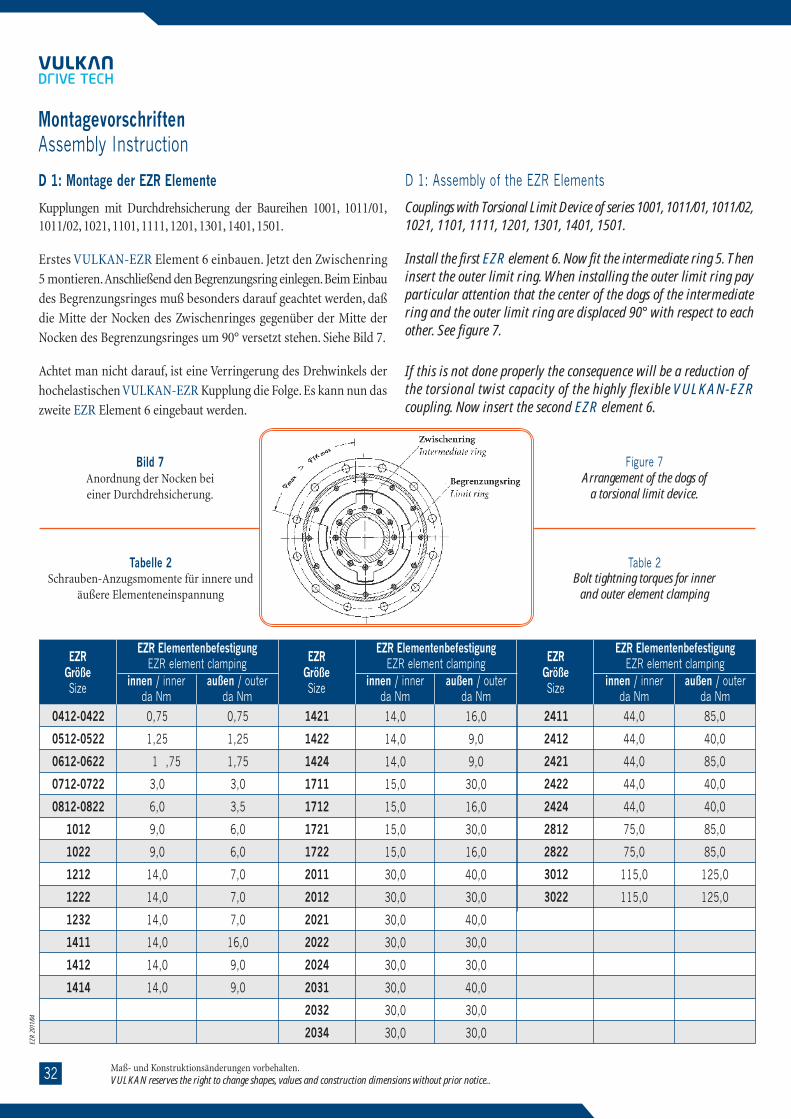
0932
EZR
2011
/04
EZR
2011
/04
Baureihen-Nr.Series No.
BaugruppeDimens.Group
MaßblattSeite
Data SheetPage
Gewicht JSeite
Weight JPage
BeschreibungDescription
Elementenwechsel durchVerschieben der
verbundenen Maschinen.Replacement of elements
by moving theadjacted machinery.
Zur Verbindung eines Schwungradesoder ähnlichemmit einer Welle
For connecting a flywheelor similar part to a shaft
Zur Verbindung eines Schwungradesoder ähnlichemmit einer Welle
For connecting a flywheelor similar part to a shaft
Zur Verbindung eines SAE- SchwungradesJ 620 mit einer Welle
For connecting a SAE flywheelJ 620 to a shaft
Zur Verbindung eines Schwungradesoder ähnlichemmit einer Welle
For connecting a flywheelor similar part to a shaft
Zur Verbindung eines Schwungrades mitSAE- Abmessungenmit einer Welle.For connecting a flywheel with SAE
dimensions to a shaft.
Elementenwechsel durchVerschieben der
verbundenen Maschinen.Replacement of elements
by moving theadjacted machinery.
Elementenwechsel durchVerschieben der
verbundenen Maschinen.Replacement of elements
by moving theadjacted machinery.
Elementenwechsel ohne Verschieben derverbundenen Maschinen. Durch
Zurückziehen des Flanschmantels undAusbau des Distanzringes
können die Elemente senkrechtausgebaut werden.
Replacement of elements without moving the adjacted machinery. The
elements can be removed vertically bymoving the flanged casing and
removing the adapter ring.
Adapterflansch mit SAE-Anschlußmaßen.Elementenwechsel ohne Verschieben der
verbundenen Maschinen.Durch Zurückziehen des Flanschmantelsund Ausbau des Adapterflansches könnendie Elemente senkrecht ausgebaut werden.
Adapter flange with dimensionsfor SAE connection. Peplacement of
elements without moving the adjacentmachinery. The elements can be removedvertically by displacing the flanged cas-
ing and removing the adapter flange.
TKN
kNm
o.D.1) m.D.2)
1000 1001
0402--
3002
0402--
1402
0,4--
200
0,4--
20
0402--
1402
0,4--
20
0402--
3002
0,4--
200
0402--
1202
0,4--
12,5
13
14
15
16
17
23
2324
24
25
2526
1010/011010/02
1010/011010/02
1020 1021
1100 1101
1110 1111
BaureihenübersichtSummary of Series
Maß- und Konstruktionsänderungen vorbehalten.VULKAN reserves the right to change shapes, values and construction dimensions without prior notice..
MontagevorschriftenAssembly Instruction
Maß- und Konstruktionsänderungen vorbehalten.VULKAN reserves the right to change shapes, values and construction dimensions without prior notice..
D 1: Montage der EZR Elemente
Kupplungen mit Durchdrehsicherung der Baureihen 1001, 1011/01,1011/02, 1021, 1101, 1111, 1201, 1301, 1401, 1501.
Erstes VULKAN-EZR Element 6 einbauen. Jetzt den Zwischenring5 montieren.Anschließend den Begrenzungsring einlegen.Beim Einbaudes Begrenzungsringes muß besonders darauf geachtet werden, daßdie Mitte der Nocken des Zwischenringes gegenüber der Mitte derNocken des Begrenzungsringes um 90° versetzt stehen. Siehe Bild 7.
Achtet man nicht darauf, ist eine Verringerung des Drehwinkels derhochelastischen VULKAN-EZR Kupplung die Folge. Es kann nun daszweite EZR Element 6 eingebaut werden.
D 1: Assembly of the EZR Elements
Couplings with Torsional Limit Device of series 1001, 1011/01, 1011/02,1021, 1101, 1111, 1201, 1301, 1401, 1501.
Install the first EZR element 6. Now fit the intermediate ring 5. Theninsert the outer limit ring. When installing the outer limit ring payparticular attention that the center of the dogs of the intermediatering and the outer limit ring are displaced 90° with respect to eachother. See figure 7.
If this is not done properly the consequence will be a reduction ofthe torsional twist capacity of the highly flexible VULKAN-EZRcoupling. Now insert the second EZR element 6.
EZRGrößeSize
EZR ElementenbefestigungEZR element clamping
innen / innerda Nm
außen / outerda Nm
EZRGrößeSize
EZR ElementenbefestigungEZR element clamping
innen / innerda Nm
außen / outerda Nm
EZRGrößeSize
EZR ElementenbefestigungEZR element clamping
innen / innerda Nm
außen / outerda Nm
0412-0422
0512-0522
0612-0622
0712-0722
0812-0822
1012
1022
1212
1222
1232
1411
1412
1414
1421
1422
1424
1711
1712
1721
1722
2011
2012
2021
2022
2024
2031
2032
2034
2411
2412
2421
2422
2424
2812
2822
3012
3022
0,75
1,25
1 ,75
3,0
6,0
9,0
9,0
14,0
14,0
14,0
14,0
14,0
14,0
0,75
1,25
1,75
3,0
3,5
6,0
6,0
7,0
7,0
7,0
16,0
9,0
9,0
14,0
14,0
14,0
15,0
15,0
15,0
15,0
30,0
30,0
30,0
30,0
30,0
30,0
30,0
30,0
16,0
9,0
9,0
30,0
16,0
30,0
16,0
40,0
30,0
40,0
30,0
30,0
40,0
30,0
30,0
44,0
44,0
44,0
44,0
44,0
75,0
75,0
115,0
115,0
85,0
40,0
85,0
40,0
40,0
85,0
85,0
125,0
125,0
Bild 7Anordnung der Nocken beieiner Durchdrehsicherung.
Figure 7Arrangement of the dogs of
a torsional limit device.
Tabelle 2Schrauben-Anzugsmomente für innere und
äußere Elementeneinspannung
Table 2Bolt tightning torques for inner
and outer element clamping

3308
EZR
2011
/04
EZR
2011
/04
Hinweise zu den Listen der Technischen Daten1. Bei der Auswahl der Kupplungen sind die Dauerleistungender Motoren zugrundezulegen. Überleistungen, Höchst- und Kurzhöchstleistungen nach DIN 6271 brauchen nicht berücksichtigtzu werden.
Reference for the Lists of Technical Data1.When selecting the couplings the permanent outputs of the engines areto be taken as a basis.Overloads,peak and short peak outputs ace.to DIN 6271need not to be taken into consideration. torsional vibration conditionswill be achieved in almost any case.
2. Bezugsgröße; die zulässige Größe !Kr ergibt sich nach unten-stehender Beziehung unter Berücksichtigung der Faktoren Sn und S".
3. Falls größere Adapterflansche verwendet werden, muß diezulässige Umfangsgeschwindigkeit überprüft werden.
4. Die Ausrichttoleranz beim Einbau ist kleiner als der zulässigeKupplungsversatz, empfohlene Ausrichttoleranzen siehe Seite 37.
5. Die aufgeführten Werte beziehen sich auf die dynamische Dreh- federsteife der progressiven Elemente bei f=10 Hz und " 303 K (30°C).
6. Die statischen Drehwinkel sind ermittelt aus den Mittelpunktskurven der Hysteresisschleife mit einer Amplitude von ± 1,5 TKN
7. Werte sind statisch ohne Drehmomentbelastung der Kupplung ermittelt.
2. Reference value; the permissible value !Kr (see below) on considerationof the factors Sn and S".
3. When using larger adapter flanges you have to check the permissiblecircumferential speed.
4. The alignment tolerance for the installation is smaller than the permissiblecoupling displacement,recommended alignment tolerances see dimensionspage 37.
5. The stated values refer to the dynamic torsional stiffness of the progressive elements at f=10 Hz and "303 K (30°C).
6. The static torsional angles are based on the average value obtained fromthe hysteresis curves with an amplitude of ± 1,5 TKN
7. Values are measured statically without torque load on the coupling.
zulässiger radialer Wellenversatzpermissible radial shaft displacement
Dynamische Drehfedersteife für beliebige FrequenzenDynamic Torsional Stiffness for various frequencies
Technische AngabenTechnical Data
Maß- und Konstruktionsänderungen vorbehalten.VULKAN reserves the right to change shapes, values and construction dimensions without prior notice..
TN=9,550 . [kNm]PN[kW]
nN[1/min]TN# TKN
!Rn = !Kn ‘ · Sn · S" CT dyn = CT dyn . Stc
Stc = 0,95 + 0,005 . fn < 500 U/mín : Sn =n < 500 U/mín : Sn = 1
" # 333 K (60ºC) : S" = 1" # 333 K (60ºC) : S" = 0,6
Drez
ahlfa
ktor
Rota
tiona
l spe
edfa
ctor
S n
Winkelgeschwindigkeit Angular velocity 10
2
1
0,5 0,4 0,3
0,2 50 100 200 500 1000 2000 5000 1/min
Drehzahl n Rotational speed
20 50 100 200 500 rad/s n
Freq
uenz
fakt
orFr
eque
ncy
fact
or S
fc
fFrequenzFrequency
(HZ)
500n
MontagevorschriftenAssembly Instruction
Maß- und Konstruktionsänderungen vorbehalten.VULKAN reserves the right to change shapes, values and construction dimensions without prior notice..
E: Montage des InnenteilesDeckel 4 mit Spannhülsen 10 einbauen. Es werden nun dieSechskantschrauben 9 mit Federscheiben 14 leicht eingeschraubt.Sechskantschrauben 7 vorschlagen und Sechskantmuttern 12 aufschrauben.Pos. 9 und Pos. 12 werden nun gleichzeitig aber stu-fenweise inUmfangsrichtung angezogen bis der Deckel 4 vor der Nabe 2 anliegt.Die Spannhülsen sind gegebenenfalls nachzuschlagen. DieSechskantmuttern sind nach Tabelle 2, die Sechskantschrauben 9nach Tabelle 1 anzuziehen.
F: Montage des AußenteilesAußendeckring 3 einlegen und den Flanschmantel 1 über die EZRElemente schieben. Die Spannhülsen 11 greifen jetzt bereits inden Außendeckring 3. Nun können die Sechskantschrauben 8mit Federscheiben 13 stufenweise in Umfangsrichtung angezogenwerden.Die Sechskantschrauben 8 sind exakt mit den Anzugsmomentennach Tabelle 2 anzuziehen.
Damit der Montagevorgang am äußeren Kupplungsteil besser kontrolliertwerden kann, sind im Flanschmantel 1 Montageöff-nungen.
AusrichthinweiseUm eine einwandfreie Funktion der VULKAN-EZR Kupplung undder verbundenen Maschinen zu gewährleisten, empfehlen wie dienachstehenden Ausrichthinweise zu beachten.
Nachdem dieVULKAN-EZR Kupplung in die Antriebsanlage eingebautist,kann die Ausrichtung der Anlage an der Kupplung kontrolliert werden.
Bei der Ausrichtkontrolle müssen folgende Maße überprüft werden:
1. Radiale Ausrichtung2. Axiale Ausrichtung
3. Winklige Ausrichtung
Bei allen EZR Kupplungen wird mit geeigneten Instrumenten(Lineal,Schieblehre,Tiefenmaß,Meßuhr etc.) an vier um 90° ver-setztenPunkten das Maß x und r gemessen (siehe Bild 9).
Sollte die Kupplung schlecht zugänglich sein, so genügen drei um 90°versetzte Meßwerte. Der vierte Wert kann durch Berechnung ermitteltwerden.
Es wird empfohlen, vor Ermittlung eines jeden einzelnen der 4 (3)Einzelwerte beide Wellen jeweils um 90° zu drehen, so daß in den
E: Montage des InnenteilesInsert the spring dowels 10 into the clamping ring 4. Now start thehexagon bolts 9 and the spring washers 14. Knock in the hexagonbolts 7 and screw on the hexagon nuts 12. Item 9 and item 12 shouldnow be tightened simultaneously, but gradually, in a circumferentialdirection until the clamping ring 4 is flat against the hub 2. If neces-sary,drive home the spring dowels. The hexagon nuts 12 must be tightenedto the exact torques given in the table 2, the hexagon bolts 9 to theexact torques given in table 1.
F: Assembly of the Outer PartInsert the outer clamping ring 3 and push the flanged casing 1 overthe EZR elements. The spring dowels are now already located into theouter clamping ring 3. Now tighten the hexagon bolts 8 with springwashers 14, gradually, in a circumferential direction. The hexagonbolts 8 must be tightened to the exact torques given in table 2.
In order that the reassembly may be simplified and, if necessary,adjusted, the flanged casing 1 is provided with access holes.
Alignment InstructionsIn order to ensure a precise functioning of the VULKAN-EZR couplingand its connected machines it is recommended that the alignmentinstructions given below are observed.
After having installed the VULKAN-EZR coupling the proper alignmentof the system can be checked at the coupling.
The system should be checked for:
1. radial alignment2. axial alignment
3. angular alignment
The dimension x and r on all EZR couplings can be measured at fourpoints displaced by 90° utilizing suitable instruments i. e. ruler slidegauge, depth gauge, dial gauge etc. (see figure 9).
If the coupling is not easily accessible it will be sufficient to take threereadings displaced by 90°. The fourth value can be found bycalculation.
In measuring each of the 4 (3) indicated single dimensions it isrecommended that both shafts be turned by 90° so that measure-

0734
EZR
2011
/04
EZR
2011
/04
C3)
kN/mmCr
kN/mmCrdynP3)
kNm/rad
axial radial 0,10 TKN 0,25 TKN 0,50 TKN 0,75 TKN 1,00 TKN
¥
Verhältnismäßige Dämpfungrelative damping
GrößeSize
Dynamische Drehfedersteife 5)bei Bezugsfrequenz 10 Hz und Bezugstemperatur 303 K (30°C)
Dynamic Torsional Stiffness atrefering frequency of 10 Hz refering temperature of 303 K (30°C)
Federsteife 7)
Stiffness
0,25
0,25
0,45
0,45
0,50
0,50
0,65
0,65
0,85
0,85
1,10
1,30
1,40
1,40
1,40
2,10
2,10
1,90
2,30
2,90
3,25
3,25
3,90
3,90
6,00
6,00
9,00
9,00
0,30
0,30
0,50
0,50
0,60
0,60
0,95
0,95
0,90
0,90
1,30
1,40
1,60
1,60
1,60
2,40
2,40
2,00
2,70
3,75
3,85
3,85
4,10
4,00
6,00
6,00
10,00
10,00
2,2
2,2
2,5
2,5
4,4
4,5
6,3
7,2
12,8
15,2
22,7
21,9
33
34
39
60
53
81
98
171
214
219
257
290
419
514
595
643
2,6
2,9
3,2
3,3
5,4
5,9
8,0
9,6
14,8
19,8
27,0
27,6
42
45
52
75
77
110
138
211
243
262
324
428
590
733
881
1050
3,7
4,4
4,9
5,6
8,2
9,8
12,7
16,0
22,7
32,8
40,5
44,6
61
74
92
124
143
186
246
324
357
462
567
771
1010
1310
1600
2050
5,5
6,8
7,3
8,6
12,1
15,3
19,2
24,7
33,7
49,8
60,0
71,4
90
114
146
191
239
284
386
493
562
781
924
1240
1530
2100
2570
3460
7,7
9,6
10,2
11,9
18,0
21,3
26,9
34,7
46,9
72,0
83,0
101,0
125
161
205
267
350
397
537
717
838
1170
1380
1800
2140
3060
3810
5310
1,13
1,13
1,13
1,13
1,13
1,13
1,13
1,13
1,13
1,13
1,13
1,13
1,13
1,13
1,13
1,13
1,13
1,13
1,13
1,13
1,13
1,13
1,13
1,13
1,13
1,13
1,13
1,13
0412
0422
0512
0522
0612
0622
0712
0722
0812
0822
1012
1022
1212
1222
1232
1412
1422
1712
1722
2012
2022
2032
2412
2422
2812
2822
3012
3022
Liste der Technischen DatenList of Technical Data
Maß- und Konstruktionsänderungen vorbehalten.VULKAN reserves the right to change shapes, values and construction dimensions without prior notice..
MontagevorschriftenAssembly Instruction
Maß- und Konstruktionsänderungen vorbehalten.VULKAN reserves the right to change shapes, values and construction dimensions without prior notice..
verschiedenen Lagen immer am gleichen Punkt der beiden Kupplungsteilegemessen wird.Bei dieser Meßmethode ist der Einfluß von Rundlauffehlernbzw. Planlauffehlern ausgeschlossen.
Kann die Anlage nicht gedreht werden, so ist eine Messung an vierverschiedenen Meßpunkten um jeweils 90° versetzt – mit ausreichenderGenauigkeit – möglich. Hierbei werden Rundlauf- bzw.Planlauffehler jedoch mitgemessen.
ments in the different positions will always be carried out at the samepoint of both coupling parts. Thus the influence of run-out andparallel misalignment is avoided.
If the system cannot be turned, measurements taken at four differentpoints,each displaced by 90° and with sufficient accuracy,are acceptable.However with this method, eccentric and parallel misalignment errorsare included in the measurements.
Bild 9a) Messung der Maße r zur Ermittlung des radialen Wellenversatzesb) Messung der Maße x zur Ermittlung des axialen und winkligen Wellenversatzesc) Meßpunkt A in 4 verschiedenen Lagen, um jeweils 90° gedreht, gemessen.
Figure 9a) Measurement of dimensions r for obtaining the radial shaft displacement.b) Measurement of dimension x for obtaining the axial and angular shaft displacement.c) Measuring points displaced by 90°.
Bild 8Bild 8 zeigt die verschiedenen Verlagerungsmöglichkeiten:
a) radiale Verlagerung ! Wrb) axiale Verlagerung ! Wac) winklige Verlagerung ! WW
In der Praxis wird die winklige Verlagerung zweckmäßig amRadius R als Axialmaß !Wa gemessen.
Figure 8Diagram 8 shows the different misalignments possible.
a) radial displacement ! Wrb) axial displacement !Wac) angular displacement !W W
In practice the angular shaft displacement will be measured as anaxial dimension !Wa at radius R.

3506
EZR
2011
/04
EZR
2011
/04
Größe Size
BaugruppeDimension
Group
Zulässige DrehmomentgrößePermissible Torque Values
NenndrehmomentNorminal Torque
TKN1)
kNmTKmax
kNmTKw
kNmPkv
kWnK max3)
1/min!Kamm
!Kr2)
mm!Kr maxmm
TKN6)
º
Maximal-drehmoment
Max.Torque
Zul. Wechsel-Drehmoment
Perm. VibratoryTorque
Statischer DrehwinkelStatic
Torsional Angle
Verl. VerlustleistungPerm.
Power Loss
Zul. DrehzahlPermissible
Rotational Speed
Material GGG axial radial max. radial
Zul. Kupplungsversatz 4)
Permissiblecoupling Displacement
0412
0422
0512
0522
0612
0622
0712
0722
0812
0822
1012
1022
1212
1222
1232
1412
1422
1712
1722
2012
2022
2032
2412
2422
2812
2822
3012
3022
0402
0402
0502
0502
0602
0602
0702
0702
0802
0802
1002
1002
1202
1202
1202
1402
1402
1702
1702
2002
2002
2002
2402
2402
2802
2802
3002
3002
0,40
0,50
0,63
0,75
1,00
1,25
1,60
2,00
3,15
4,00
5,00
6,30
8,00
10,00
12,50
16,00
20,00
25,00
31,50
40,00
50,00
63,00
80,00
100,00
125,00
160,00
200,00
250,00
1,20
1,50
1,90
2,30
3,00
3,75
4,80
6,00
9,45
12,00
15,00
18,90
24,00
30,00
37,50
48,00
60,00
75,00
94,50
120,00
150,00
189,00
240,00
300,00
375,00
480,00
600,00
750,00
0,16
0,20
0,25
0,30
0,40
0,50
0,64
0,80
1,26
1,60
2,00
2,52
3,20
4,00
5,00
6,40
8,00
10,00
12,60
16,00
20,00
25,20
32,00
40,00
50,00
64,00
80,00
100,00
5870
5870
5100
5100
4480
4480
3890
3890
3330
3330
2880
2880
2550
2550
2550
2150
2150
1840
1840
1540
1540
1540
1340
1340
1170
1170
1080
1080
3,5
3,5
4,0
4,0
4,5
4,5
5,0
5,0
6,0
6,0
7,0
7,0
7,5
7,5
7,5
8,0
8,0
9,0
9,0
10,0
10,0
10,0
11,0
11,0
12,0
12,0
13,0
13,0
1,0
1,0
1,2
1,2
1,4
1,4
1,6
1,6
1,9
1,9
2,2
2,2
2,5
2,5
2,5
2,9
2,9
3,5
3,5
4,0
4,0
4,0
4,5
4,5
5,0
5,0
5,5
5,5
2,0
2,0
2,5
2,5
3,0
3,0
3,5
3,5
4,0
4,0
4,5
4,5
5,0
5,0
5,0
6,0
6,0
7,0
7,0
8,0
8,0
8,0
9,0
9,0
10,0
10,0
11,0
11,0
0,03
0,03
0,04
0,04
0,06
0,06
0,13
0,13
0,20
0,20
0,35
0,35
0,60
0,60
0,60
1,02
1,02
1,64
1,64
3,02
3,02
3,02
4,95
4,95
7,45
7,45
10,50
10,50
11,0
12,5
12,0
13,5
13,0
14,5
13,5
15,5
17,0
17,0
14,0
15,5
15,5
16,0
18,0
17,0
17,5
18,0
17,0
15,0
15,0
16,5
19,0
19,5
14,5
15,5
14,5
16,5
Liste der Technischen DatenList of Technical Data
Maß- und Konstruktionsänderungen vorbehalten.VULKAN reserves the right to change shapes, values and construction dimensions without prior notice..
MontagevorschriftenAssembly Instruction
Maß- und Konstruktionsänderungen vorbehalten.VULKAN reserves the right to change shapes, values and construction dimensions without prior notice..
Je genauer die Antriebsanlage ausgerichtet wird, um so mehr Reservensind für die Aufnahme von radialen,axialen und winkligen Verlagerungenfür die Kupplungen während des Betriebes vorhanden.
Für Anlagen mit extrem großen Verlagerungen während des Betriebeskann mit Rücksicht auf eine günstige Beeinflussung der FederkräfteFr und Fa die hochelastische EZR Kupplung in kaltem, unbelastetemZustand mit dem entsprechenden Versatz in entgegengesetzterRichtung eingebaut werden. Voraussetzung für diesen Fall ist, daßdie Größe und Richtung der Verlagerung genau bekannt ist. Wirempfehlen eine nachträgliche Kontrolle in betriebswarmem,halbbeladenem Zustand.
Bei der heutigen optimalen Auslegung von Antrieben mit Dieselmotorenist es erforderlich, die zulässigen Ausrichttoleranzen mit demMotoren-, Geriebe- oder Gerätebauer abzustimmen.
Das Beispiel auf Seite 36 zeigt die Überprüfung der Ausrichtungan der eingebauten Kupplung. Es wird hierbei nicht nur die Größe,sondern auch die Richtung der Verlagerung exakt bestimmt.
Die empfohlenen Ausrichttoleranzen für die radiale,axiale und winkligeVerlagerung im kalten Betriebszustand sind in den nachfolgendenTabellen angegeben.
The more accurately the drive system is aligned, the less the couplingcapacity to absorb, during operation, radial, axial and angular dis-placements is reduced.
For systems where extremely large misalignments are known to occur inoperation, the highly flexible EZR coupling can be installed in cold,unloaded condition, displaced in the opposite direction, in order toreduce, the axial and radial spring forces (reaction forces) Fa and Fr,which add to the bearing loads of the connected machinery.Of course, the exact magnitude and direction of the displacementsshould be known. We recommend a later check under warm operatingconditions at about half load.
With todays optimum selection of diesel engine drives it is necessaryto corelate the alignment tolerances with the engine, gear or unitmanufacturer.
The example on page 36 shows the alignment control at the installedcoupling. Not only the magnitude but also the direction of misalignmentwill be exactly determined by this method.
The recommended alignment tolerances for the radial, axial an angularshaft displacements in cold operation condition are given in thefollowing tables.
EZRGröße / Size
Radiale Ausrichtungstoleranzradial alignment tolerance
Tabelle 3 / Table 3 Tabelle 4 / Table 4 Tabelle 5 / Table 5
0412-0622
0712-1022
1211-1722
2011-2822
3012-3022
0412-0622
0712-1022
1211-1722
2011-2822
3012-3022
0 ± 0,30 mm
0 ± 0,40 mm
0 ± 0,50 mm
0 ± 0,60 mm
0 ± 0,70 mm
0 ÷ 0,10 mm
0 ÷ 0,20 mm
0 ÷ 0,35 mm
0 ÷ 0,50 mm
0 ÷ 0,60 mm
0 ÷ 0,10 mm
0 ÷ 0,20 mm
0 ÷ 0,35 mm
0 ÷ 0,50 mm
0 ÷ 0,60 mm
0412-0622
0712-1022
1211-1722
2011-2822
3012-3022
EZRGröße / Size
Radiale Ausrichtungstoleranzradial alignment tolerance
EZRGröße / Size
Radiale Ausrichtungstoleranzradial alignment tolerance

0536
EZR
2011
/04
´
Die Nabe 2 wird auf die Welle aufgezogen. An ihr sind die beidenelastischen EZR Elemente 7 mit den inneren Befestigungsschrauben 8befestigt. Der Zwischenring 5 und der Deckel 4 sorgen für einensicheren Halt.Außen befindet sich eine ähnliche Verbindung zwischenden EZR Elementen und dem Flanschmantel 1.Sie erfolgt mittels der äußeren Befestigungsschrauben 9 und desAußendeckringes 3. In den Einspannstellen werden die aus demKupplungsdrehmoment herrührenden Kräfte durch Reibschlußzwischen den aufeinanderlegenden und fest angedrückten Teilenübertragen. Alle Verbindungen sind spielfrei.
DurchdrehsicherungEZR Kupplungen können mit einer Durchdrehsicherung, Bild 2,ausgerüstet werden. Die Nocken am Innenteil 1 und am Außen-teil2 kommen erst nach Überschreiten des zulässigen maximalenDrehmomentes zum Anschlag. Beim Bruch der EZR Elementeermöglicht die Durchdrehsicherung einen Notbetrieb mit begrenztemDrehmoment.
EZR Kupplungen mit Durchdrehsicherung ergeben besondere Baureihen.
The hub 2 is pushed onto the shaft. Both flexible EZR elements 7 areconnected to it by the inner clamping bolts 8. The intermediate ring5 and the cover 4 ensure a firm grip. The EZR elements are similarlyconnected to the flange casing by the outer clamping bolts 9 andthe outer clamping ring 3. At the clamping areas the forces resultingfrom the coupling torque are transmitted by the friction between thefirmly clamped parts. All connections are clear from play.
Torsional limit deviceEZR couplings can be supplied with a torsional limit device, figure2. The dogs on the inner part 1 and the outer part 2 come into contactonly when the permissible maximum torque is exceeded. Should theEZR elements fail, the torsional limit device would serve as anemergency drive on limited torque.
EZR couplings with torsional limit device are listed as special series.
Maß- und Konstruktionsänderungen vorbehalten.VULKAN reserves the right to change shapes, values and construction dimensions without prior notice..
Bild 2EZR Kupplungmit Durchdrehsicherung.
1 Innenteil2 Außenteil
Der Drehwinkel max. derDurchdrehsicherung ist größerals der Drehwinkel TK max.beim zulässigen maximalenDrehmoment.
Figure 2EZR couplingwith torsional limit device.
1 inner part2 outer part
The torsional angle max. ofthe torsional limit device is largerthan the torsional angle TK max.at the permissible maximumtorque.
MontagevorschriftenAssembly Instruction
Maß- und Konstruktionsänderungen vorbehalten.VULKAN reserves the right to change shapes, values and construction dimensions without prior notice..
BeispielHochelastische VULKAN-EZR Kupplung Größe 1212Baureihe 1200
A: Radiale Ausrichtung
ExampleHighly flexible VULKAN-EZR coupling Size 1212Series 1200
A: Radial Alignment:
Bild 10Radiale Wellenverlagerung !Wr
Figure 10radial displacement !Wr
!Wr12 = r2 -r 1 =
143,2 - 144,3= -0,55 mm
2 2
!Wr34 = r3 -r 4 =
143,0 - 144,5= -0,75 mm
2 2
!Wr = !Wr122 + !Wr342 !Wr == 0,552 + 0,752 = 0,93 mm
Der Kupplungseinbau muß korrigiert werden bis !Wr < 0,35 mmist. Siehe Tabelle 3 Seite 35.
B: Axiale Ausrichtung
The coupling installation must be corrected until !Wr 0,35 mm is.See Table 3 page 35.
B: Axial Alignment
Bild 11Axiale Wellenverlagerung !Wa
Figure 11axial shaft displacement !Wa
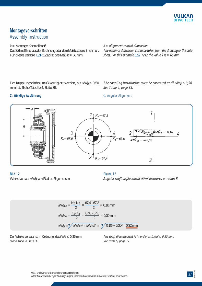
3704
EZR
2011
/04
Die hochelastische VULKAN-EZR Kupplung ist eine allseitig nach-giebige Gummigewebekupplung. Die Verwendung von Kunstfasergeweben gewährleistet eine hohe Festigkeit. Sie kommt überallda zum Einsatz, wo zwei ungefähr gleichachsige, umlaufendeMaschinenteile elastisch miteinander zu verbinden sind. Wegen derMöglichkeit der Auswahl von verschiedenen Drehfedersteifigkeitenund Dämpfungen ergeben sich fast immer günstige Drehschwing-ungszustände.
Konstruktiver AufbauDen wesentlichen Teil der EZR Kupplung bilden die hochelastischenElemente, deren besondere Eigenschaften an anderer Stelle näherbeschrieben sind. Die elastischen Elemente werden an ihreminneren und äußeren Umfang durch Schrauben mit den Metallteilenverbunden.Je nach Art der miteinander zu ver-bindenden umlaufendenMaschinenteile ist die Gestaltung der Metallteile eine andere.Hieraus ergeben sich die verschiedenen Baureihen (s.Baureihenübersicht).
Für viele Drehmoment-Gruppen werden unterschiedliche Drehfedersteifender elastischen Elemente angeboten.
Kupplungen mit geringer Drehsteife weisen einen größerenAußendurchmesser auf, als Kupplungen mit hoher Drehsteife.Um die durch die Dämpfung in Wärme umgesetzte Schwingungsenergiesicher abführen zu können, werden die Oberflächen der elastischenElemente sowohl außen als auch innen zwangsbelüf-tet.
Bild 1 zeigt eine Kupplung für die Verbindung eines Schwungradesmit einer Welle.
The highly flexible VULKAN-EZR coupling is a fabric reinforcedrubber coupling with multidirectional flexibility. The use of syntheticfibre guarantees high strength. They can be employed in all thoseapplications where two approximately co-axially rotating machineshave to be flexibly connected. Due to the possibility to select fromvarious torsional stiffness and damping characteristics, satisfactorytorsional vibration conditions will be achieved in almost any case.
ConstructionThe essential part of the EZR coupling is formed by the highly fle-xibleelements, whose inherent properties are described later in thetext. The flexible elements are connected to the metal parts by meansof bolts at their inner and outer circumferences. The design of themetal parts depends upon the type of connection required by therotating machines, resulting in various configurations or series (seesurvey of series).
In many torque-groups, different torsional stiffnesses are offered.
Couplings with lower stiffness have a larger outer diameter than thosewith higher stiffness.In order to ensure the removal of the heat, into which, by damping,a part of the vibration energy is transformed, a forced ventilationof the internal and external surfaces of the flexible elements is provided.
Fig. 1 shows a coupling suitable for the connection of a flywheel witha shaft.
Die hochelastischen VULKAN-EZR KupplungThe Highly Flexible VULKAN-EZR Coupling
Maß- und Konstruktionsänderungen vorbehalten.VULKAN reserves the right to change shapes, values and construction dimensions without prior notice..
Bild 1Schnittbild einer hochelastischenVULKAN-EZR Kupplung(Baureihe 1100 und 1101)
1 Flanschmantel2 Nabe3 Außendeckring4 Deckel5 Zwischenring (innen)6 Ausbauring7 EZR Element8 innere Befestigungsschrauben9 äußere Befestigungsschrauben10 Durchdrehsicherung11 Zwischenring (außen)
Figure 1Sectional sketch of a highly flexibleVULKAN-EZR coupling(Series 1100 and 1101)
1 flanged casing2 hub3 outer clamping ring4 cover5 intermediate ring (inner)6 disassembly ring7 EZR element8 inner clamping bolts9 outer clamping bolts10 torsional limit device11 intermediate ring (outer)
MontagevorschriftenAssembly Instruction
Maß- und Konstruktionsänderungen vorbehalten.VULKAN reserves the right to change shapes, values and construction dimensions without prior notice..
k = Montage-KontrollmaßDas Sollmaß k ist aus der Zeichnung oder dem Maßblattzu ent nehmen.Für dieses Beispiel EZR 1212 ist das Maß k = 66 mm.
k = alignment control dimensionThe nominal dimension k is to be taken from the drawing or the datasheet. For this example EZR 1212 the value k is = 66 mm
Der Kupplungseinbau muß korrigiert werden, bis !Wa " 0,50mm ist. Siehe Tabelle 4, Seite 35.
C: Winklige Ausführung
The coupling installation must be corrected until !Wa " 0,50See Table 4, page 35.
C: Angular Alignment
Bild 12Winkelversatz !Wa‘ am Radius R gemessen
Figure 12Angular shaft displacement !Wa‘ measured ar radius R
!Wa12 = K2 -K 1 =
67,4 - 67,2= 0,10 mm
2 2
!Wr34 = K3 -K4 =
67,0 - 67,6= 0,30 mm
2 2
!Wa = !Wa122 + !Wa342 = 0,102 + 0,302 = 0,32 mm
Der Winkelversatz ist in Ordnung, da !Wa‘ " 0,35 mm.Siehe Tabelle Seite 35.
The shaft displacement is in order as !Wa‘ " 0,35 mm.See Table 5, page 35.

0338
InhaltIndex
Die hochelastische VULKAN-EZR-Kupplung
The Highly Flexible VULKAN-EZR Coupling ............................................................................................................ 04
Liste der Technischen Daten
List of Technical Data .............................................................................................................................................. 06
Technische Angaben
Technical Data ......................................................................................................................................................... 08
Baureihenübersicht
Summary of Series ................................................................................................................................................. 09
Abmessungen
Dimensions .............................................................................................................................................................. 11
Gewichte und Massenträgheitsmomente
Weights and mass moments of inertia .................................................................................................................... 20
Montagevorschriften
Assembly instructions ............................................................................................................................................. 26
Hochelastische VULKAN Kupplungen
Highly Flexible VULKAN Couplings ..................................................................................................................... 38
EZR
2011
/04
Hochelastische VULKAN KupplungenHighly Flexible VULKAN Couplings
Maß- und Konstruktionsänderungen vorbehalten.VULKAN reserves the right to change shapes, values and construction dimensions without prior notice..
Die hochelastische VULASTIK-L-Kupplung ist aufgrund ihrerSteckbarkeit überwiegend bei Glockeneinbauten im Einsatz. DieAnschlußabmessungen sind entsprechend der DIN 6281 und derSAE-Norm.
Drehmomentbereich: 0,4 - 40 kNmLieferbar in Gummi- oder Silikonausführung.
Die hochelastische VULKARDAN-E Kupplung wird verwendet, um dasDrehschwingungsverhalten von Antriebsanlagen optimal abzustimmen.Durch ihre steckbare Ausführung fi ndet sie vornehmlich Anwendungin sogenannten Glockeneinbauten.
Drehmomentbereich: 0,16 - 5 kNmLieferbar in Gummi- oder Silikonausführung.
Die hochelastische VUKARDAN-E Kupplung (freistehend) fi ndetVerwendung bei der Verbindung von elastisch/starr aufgestelltenMotoren mit Getrieben oder anderen Arbeitsmaschinen. Sie ergänztdie Kupplungen der RATO-Serie im unteren Drehmomentbereich.
Drehmomentbereich: 1,6 - 20 kNmLieferbar in Gummi- oder Silikonausführung.
Die elastische TORFLEX-Kupplung mit progressiver Drehsteifi gkeitwurde speziell zur Geräuschverhinderung in Bootsantrieben konstruiert.
Drehmomentbereich: 0,25 - 1,6 kNmLieferbar in Silikon.
Für größere Leistungsbereiche bzw. härtere Einsatzfälle ist dieTORFLEX-HT geeignet.
Drehmomentbereich: 2,0 - 15 kNmLieferbar in Gummi.
The highly fl exible VULASTIK-L couplings are with „slip-on“ fea-turesand therefore they are provided mainly for installation inflanged bell-type connections. The installation dimensions correspond to DIN6281 and SAE standards.
Torque range: 0.4-40.0 kNmAvailable in both rubber and silicone.
The highly fl exible VULKARDAN-E coupling is used to tune the tor-sionalresponse of the system. It is a coupling with „slip-on“ feature and thereforeis mainly used in bell-housing installations.
Torque range: 0.16-5.0 kNmAvailable in both rubber and silicone.
The highly fl exible VULKARDAN-E free-standing coupling is used to connectfl exibly/rigidly mounted engines with gearboxes or ano-ther machinery.It completes the RATO Family in the lower torque range.
Torque range: 1.6-20.0 kNmAvailable in both rubber and silicone.
The fl exible TORFLEX coupling with a progressive torsional stiffnessspecially designed to combat gearnoise in boat reverse/reduction gearboxes.
Torque range: 0.25-1.6 kNmAvailable in silicone.
For higher torques and heavy duty applications our TORFLEX-HTis suitable.
Torque range: 2,0 - 15 kNmAvailable in rubber.
VULASTIK-L TORFLEX TORFLEX-HTVULKARDAN-E
für Glockeneinbautenbell-housing
VULKARDAN-Efreistehend
free-standing

3902
Der vorliegende Katalog ersetzt alle vorherigen Ausgaben, ältereDrucke verlieren ihre Gültigkeit.
Die Angaben in diesem Katalog beziehen sich auf den technischenStandard gültig im Hause VULKAN und unter den definiertenBedingungen laut Erläuterung im Katalog – es liegt im Ent-scheidungs-und Verantwortungsrahmen des Systemverantwort-lichen für die Antriebslinie entsprechende Rückschlüsse auf dasSystemverhalten zu ziehen. VULKAN Drehschwingungsanalysenberücksichtigen in der Regel nur das rein mechanische Schwin-gungsersatzsystem – als ein Komponentenhersteller übernimmtVULKAN mit der Analyse des Drehschwingungssystems (statio-när, transient) nicht die Systemverantwortung – die Genauigkeitder Analyse hängt von der Genauigkeit der verwendeten bzw. derVULKAN zur Verfügung gestellten Daten ab.
Änderungen aufgrund des technischen Fortschritts sind vorbe-halten. Bei Unklarheiten bzw. Rückfragen kontaktieren Sie bitteVULKAN.
This catalogue supersedes previous editions. VULKAN reserves the right toamend any details in this catalogue without notice and with-outany liability for previously supplied couplings.
The data in this catalogue refers to the technical standard as pre-sent-ly used by VULKAN with defined conditions according to theexplanations in the catalogue. The responsibility for the torsionalvibration compatibility of the complete system rest with the systemadministrator who has the responsibility and competence to makethe necessary calculation for the drive line behaviour. VULKAN tor-sional vibration analysis usually only consider the pure mechanicalmass-elastic system. As a c omponent supplier VULKAN takes nosystem responsibility according to the analysis of the torsional vibra-tionsystem (stationary, transiently). The accuracy of the analysisdepends on the exactness of the used data resp. the provided datas toVULKAN.
Any changes due to the technological progress are reserved. For ques-tions or unclear items please contact VULKAN.
Stand 04/2011Das Recht auf Vervielfältigung, Nachdruck und Übersetzungenbehalten wir uns vor.
Maß- und Konstruktionsänderungen vorbehalten.
Issue 04/2011All rights of duplication, reprinting and translation are reserved.
We reserve the right to modify dimensions and constructions withoutprior notice.
EZR
2011
/04
Hochelastische VULKAN KupplungenHighly Flexible VULKAN Couplings
Maß- und Konstruktionsänderungen vorbehalten.VULKAN reserves the right to change shapes, values and construction dimensions without prior notice..
Die hochelastische MEGIFLEX-B-Kupplung ist in alle Richtungennachgiebig. Sie wird als Flansch-Welle- oder Welle-Welle-Verbin-dung eingesetzt.
Drehmomentbereich: 0,01 - 3,15 kNmLieferbar in Gummi- oder Silikonausführung.
VULKARDAN-LVorschaltkupplung mit linearer Drehsteifi gkeit.
Drehmomentbereich: 0.16-12.5 kNm
VULKARDAN-PVorschaltkupplung mit progressiver Drehsteifi gkeit.
Drehmomentbereich: 0.32-31.5 kNm
Anfl anschaußenlagermit hochelastischer KupplungDiese Ausführung wird bei Antriebsanlagen mit hohem Beugewinkelder Gelenkwelle verwendet. Die durch die Gelenkwelle entstehen-den Reaktionskräfte werden durch das Anfl anschaußenlager aufgenom-men und reduzieren somit die Kurbelwellenbeanspruchung.
Drehmomentbereich: 0,63 - 25 kNm
The highly fl exible MEGIFLEX-B couplings are fl exible in all direc-tions. They are used to connect fl ywheel to shaft as well as shaft toshaft.
Torque range: 0.01-3.15 kNmAvailable in both rubber and silicone.
VULKARDAN-LIntermediate coupling with linear torsional stiffness.
Torque range: 0.16-12.5 kNm
VULKARDAN-PIntermediate coupling with progressive torsional stiffness.
Torque range: 0.32-31.5 kNm
Integral Shaft Supportwith highly fl exible couplingThis design will be fi tted in installations where the cardan shaft hasa large angle of inclination. The resulting lateral and axial reactionforces from the cardan shaft are supported by the bell-housing soreducing the engine crankshaft loading.
Torque range: 0.63-25.0 kNm
MEGIFLEX-B VULKARDAN-L VULKARDAN-PAnfl anschaußenlager/Integral Shaft Support

2011/04
EZREZR
www.vulkandrivetech.com
BrazilVULKAN do Brasil Ltda.Rod. Engº Constancio Cintra, km 91Bairro da Ponte – Cx Postal 141CEP 13252-200 Itatiba, São Paulo/BrasilTel. +55 11 4894-7300 · Fax +55 11 4894-7329E-Mail: [email protected]
ItalyVULKAN Italia S.R.L.Via dell´ Agricoltura 2P. O. Box 315067 Novi Ligure (AL)/ItalyTel. +39 0143 310211 · Fax +39 0143 329740E-Mail: [email protected]
IndiaVulkan Technologies Pvt Ltd S.No.539-B ,Kasar Amboli ,Tal.Mulshi Pirangut Industrial Area .Ghotawade Dist Pune -412111 - India Tel. -[91-20 ] 66765526 - Fax -[91-20] 66765551 E-mail: [email protected]
KoreaVULKAN Korea Co.4th floor, Samsung Haeundae Bldg.1153-8, Jung 1-Dong, Haundae-GuBusan 612-847,KoreaTel. +82 51 2562473 ˆ Fax +82 51 2562474E-Mail: [email protected]
GermanyVULKAN Kupplungs- undGetriebebau GmbH & Co. KGHeerstr. 6644653 Herne/GermanyTel. +49 2325 922-0 · Fax +49 2325 71110E-Mail: [email protected]
United KingdomVULKAN Industries LTDArcher RoadArmytage Road Industrial Estate,Brighouse, W.-Yorkshire, HD6 1XF/GBTel. +44 1484 712273 - Fax +44 1484 711376E-Mail: [email protected]
ChinaWuxi VULKAN Technologies Co. Ltd.Xinzhou Road, Lot 93D-3 in Wuxi Science & TechnologyIndustrial Park, 214028 Jiangsu Prov. P.R. ChinaTel. +86 510 8534 2222 ˆ Fax +86 510 8534 2345E-Mail: [email protected]
FranceVULKAN France SA12, avenue Émile ZolaZA de l'Agavon13170 Les Pennes Mirabeau/FranceTel. +33 04 42 02 21 01 . Fax +33 04 42 02 21 09E-Mail: [email protected]
U.S.A. American VULKAN Corporation2525 Dundee RoadWinter Haven, Florida 33884/USATel. +1 863 3242424 · Fax +1 863 3244008E-Mail: [email protected]
SpainVULKAN Española S.A.Polig. Ind. MoscatelaresAvda. Montes de Oca, 19, Nave 728709 S.S. Reyes, Madrid/SpainTel. +34 91 3590971/72 · Fax +34 91 3453182E-Mail: [email protected]
Netherlands, Belgium, LuxembourgVULKAN BeneluxVan Coulsterweg 32952 CB Alblasserdam / NetherlandsTel. + 31 (0) 78 68 107 80 – Fax +31 (0) 78 68 107 99E-Mail: [email protected]
South AfricaVULKAN South AfricaUnit H6 Pinelands Office ParkArdeer RoadModderfontein,EdenvaleJohannesburg, South AfricaTel: +27 11-6084044 - Fax: +27 11-6081877E-Mail: [email protected]