Embed Size (px)
Citation preview
Type EZR Relief
D10
2629
X01
2
Instruction ManualForm 5476
October 2015
www.fisherregulators.com
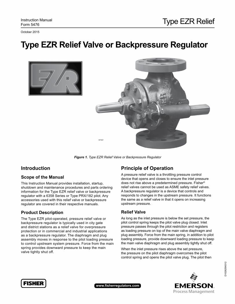
Type EZR Relief Valve or Backpressure Regulator
Figure 1. Type EZR Relief Valve or Backpressure Regulator
W7347
Introduction
Scope of the ManualThis Instruction Manual provides installation, startup, shutdown and maintenance procedures and parts ordering information for the Type EZR relief valve or backpressure regulator with a 6358 Series or Type PRX/182 pilot. Any accessories used with this relief valve or backpressure regulator are covered in their respective manuals.
Product DescriptionThe Type EZR pilot-operated, pressure relief valve or backpressure regulator is typically used in city gate and district stations as a relief valve for overpressure protection or in commercial and industrial applications as a backpressure regulator. The diaphragm and plug assembly moves in response to the pilot loading pressure to control upstream system pressure. Force from the main spring provides downward pressure to keep the main valve tightly shut off.
Principle of OperationA pressure relief valve is a throttling pressure control device that opens and closes to ensure the inlet pressure does not rise above a predetermined pressure. Fisher® relief valves cannot be used as ASME safety relief valves. A backpressure regulator is a device that controls and responds to changes in the upstream pressure. It functions the same as a relief valve in that it opens on increasing upstream pressure.
Relief ValveAs long as the inlet pressure is below the set pressure, the pilot control spring keeps the pilot valve plug closed. Inlet pressure passes through the pilot restriction and registers as loading pressure on top of the main valve diaphragm and plug assembly. Force from the main spring, in addition to pilot loading pressure, provide downward loading pressure to keep the main valve diaphragm and plug assembly tightly shut off.
When the inlet pressure rises above the set pressure, the pressure on the pilot diaphragm overcomes the pilot control spring and opens the pilot valve plug. The pilot then
Type EZR Relief
2
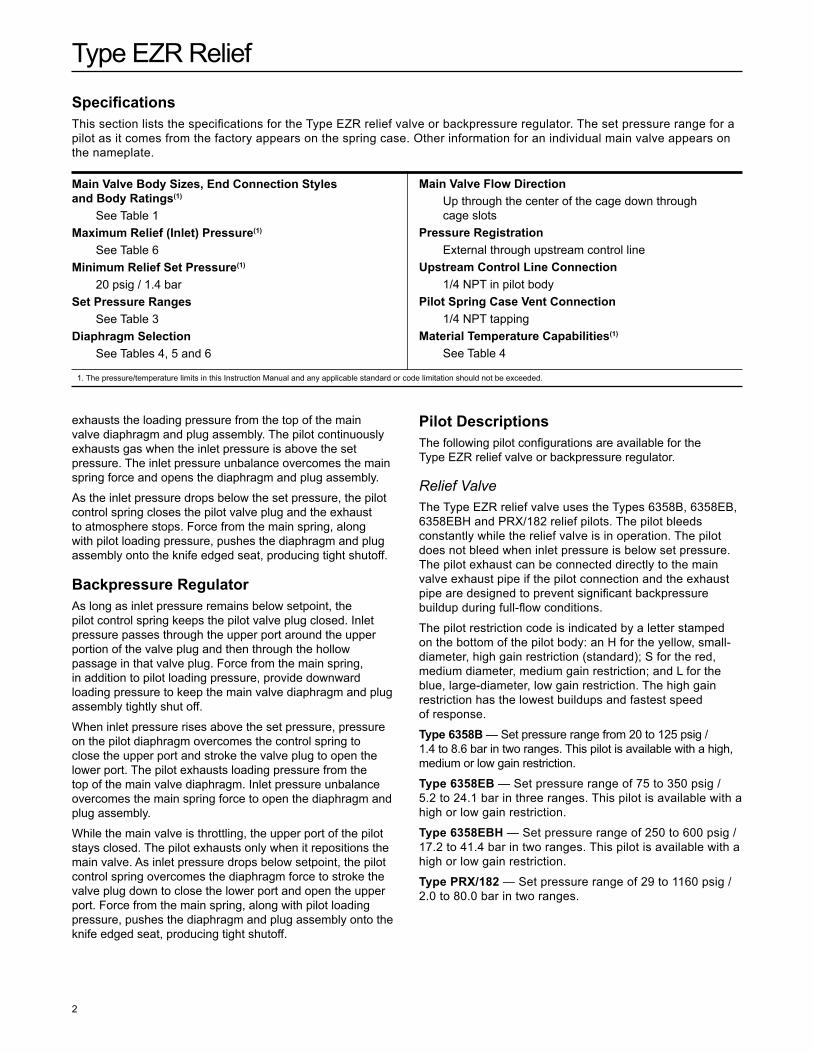
SpecificationsThis section lists the specifications for the Type EZR relief valve or backpressure regulator. The set pressure range for a pilot as it comes from the factory appears on the spring case. Other information for an individual main valve appears on the nameplate.
Main Valve Body Sizes, End Connection Styles and Body Ratings(1)
See Table 1Maximum Relief (Inlet) Pressure(1)
See Table 6Minimum Relief Set Pressure(1)
20 psig / 1.4 barSet Pressure Ranges
See Table 3Diaphragm Selection
See Tables 4, 5 and 6
Main Valve Flow DirectionUp through the center of the cage down through cage slots
Pressure RegistrationExternal through upstream control line
Upstream Control Line Connection1/4 NPT in pilot body
Pilot Spring Case Vent Connection1/4 NPT tapping
Material Temperature Capabilities(1)
See Table 4
1. The pressure/temperature limits in this Instruction Manual and any applicable standard or code limitation should not be exceeded.
exhausts the loading pressure from the top of the main valve diaphragm and plug assembly. The pilot continuously exhausts gas when the inlet pressure is above the set pressure. The inlet pressure unbalance overcomes the main spring force and opens the diaphragm and plug assembly.
As the inlet pressure drops below the set pressure, the pilot control spring closes the pilot valve plug and the exhaust to atmosphere stops. Force from the main spring, along with pilot loading pressure, pushes the diaphragm and plug assembly onto the knife edged seat, producing tight shutoff.
Backpressure RegulatorAs long as inlet pressure remains below setpoint, the pilot control spring keeps the pilot valve plug closed. Inlet pressure passes through the upper port around the upper portion of the valve plug and then through the hollow passage in that valve plug. Force from the main spring, in addition to pilot loading pressure, provide downward loading pressure to keep the main valve diaphragm and plug assembly tightly shut off.
When inlet pressure rises above the set pressure, pressure on the pilot diaphragm overcomes the control spring to close the upper port and stroke the valve plug to open the lower port. The pilot exhausts loading pressure from the top of the main valve diaphragm. Inlet pressure unbalance overcomes the main spring force to open the diaphragm and plug assembly.
While the main valve is throttling, the upper port of the pilot stays closed. The pilot exhausts only when it repositions the main valve. As inlet pressure drops below setpoint, the pilot control spring overcomes the diaphragm force to stroke the valve plug down to close the lower port and open the upper port. Force from the main spring, along with pilot loading pressure, pushes the diaphragm and plug assembly onto the knife edged seat, producing tight shutoff.
Pilot DescriptionsThe following pilot configurations are available for the Type EZR relief valve or backpressure regulator.
Relief ValveThe Type EZR relief valve uses the Types 6358B, 6358EB, 6358EBH and PRX/182 relief pilots. The pilot bleeds constantly while the relief valve is in operation. The pilot does not bleed when inlet pressure is below set pressure. The pilot exhaust can be connected directly to the main valve exhaust pipe if the pilot connection and the exhaust pipe are designed to prevent significant backpressure buildup during full-flow conditions.
The pilot restriction code is indicated by a letter stamped on the bottom of the pilot body: an H for the yellow, small-diameter, high gain restriction (standard); S for the red, medium diameter, medium gain restriction; and L for the blue, large-diameter, low gain restriction. The high gain restriction has the lowest buildups and fastest speed of response.
Type 6358B — Set pressure range from 20 to 125 psig / 1.4 to 8.6 bar in two ranges. This pilot is available with a high, medium or low gain restriction.
Type 6358EB — Set pressure range of 75 to 350 psig / 5.2 to 24.1 bar in three ranges. This pilot is available with a high or low gain restriction.
Type 6358EBH — Set pressure range of 250 to 600 psig / 17.2 to 41.4 bar in two ranges. This pilot is available with a high or low gain restriction.
Type PRX/182 — Set pressure range of 29 to 1160 psig / 2.0 to 80.0 bar in two ranges.
Type EZR Relief
3
Backpressure RegulatorThe Type 6358 is a low bleed pilot, so it only exhausts while it is repositioning the main valve. There is no constant bleed with this construction which is useful for backpressure applications where minimizing emissions is important and the pilot exhaust can not be piped to the downstream piping. This also minimizes dirt buildup in the pilot. The Types PRX/182, 6358B, 6358EB and 6358EBH pilots can also be used in backpressure applications but they will exhaust any time inlet pressure is above setpoint.
Type 6358 — Set pressure range from 20 to 125 psig / 1.4 to 8.6 bar in two ranges. This pilot has a restriction plug.
Optional Travel IndicatorThe travel indicator responds with the precise movement of the diaphragm and plug assembly to show actual valve position. A travel indicator can be used for in-line inspection and troubleshooting, and remote stem positioning and alarming when combined with the Type 4310 or 4320 wireless position monitor.
Optional Inlet StrainerThe stainless steel inlet strainer is designed with holes smaller than the cage slots to prevent pipeline debris from becoming trapped in the main valve body. Once trapped in the body, the debris can clog the cage slot affecting shutoff performance. Inlet strainers are typically not used on relief valves because debris can clog the strainer, restricting the flow through the body.
Optional Pilot Supply FilterThe Type 252 pilot supply filter prevents pipeline debris from entering the pilot; a primary cause of pilot clogging. The aluminum body is rated for 2150 psig / 148 bar and the stainless steel body for 2750 psig / 190 bar. Both are available in standard or extended length with a pipe plug or a drain valve. When the upstream system is free of debris, the Type EZR may be installed without a filter. Pilot supply filters are not typically used on relief valves because debris can plug the filter, hampering pilot operation.
Installation
! WaRnIng
Personal injury, equipment damage or leakage due to escaping gas or bursting of pressure-containing parts may result if the Type EZR is installed where its capabilities can be exceeded or where conditions exceed any ratings of the adjacent piping or connections. To avoid this, install a Type EZR relief valve or backpressure regulator where: • Service conditions are within unit
capabilities (including those in the Specifications section)
• Service conditions are within applicable codes, regulations or standards
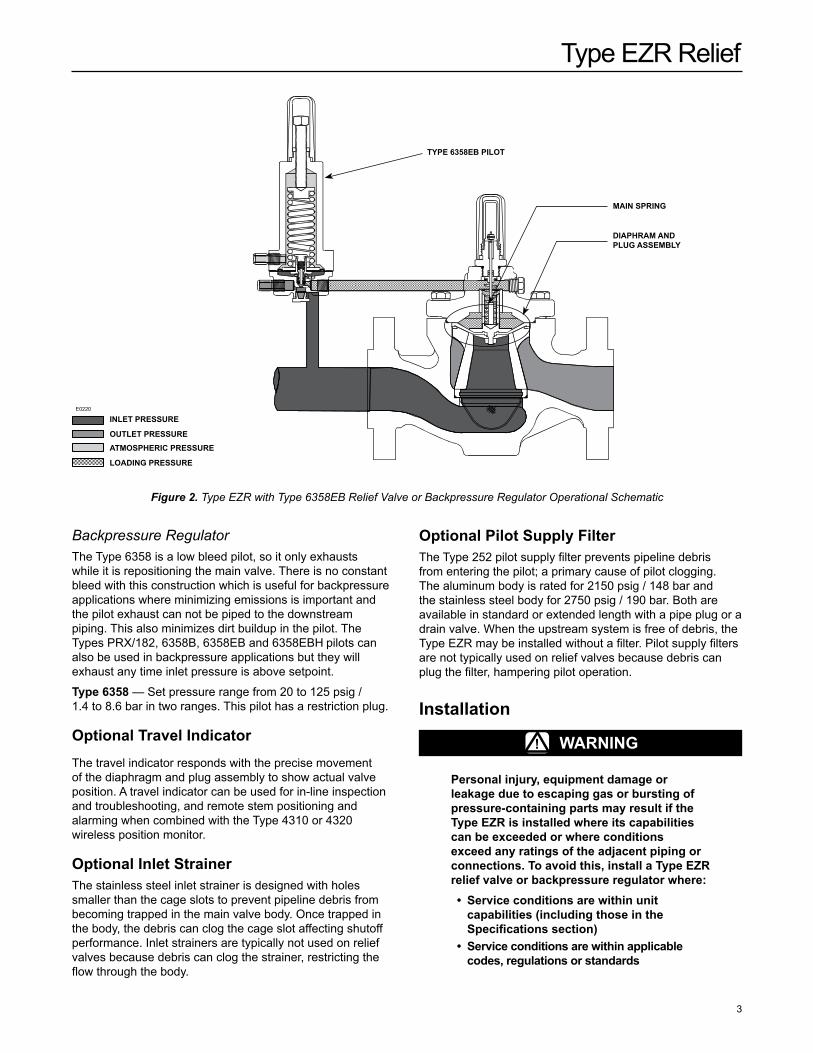
Figure 2. Type EZR with Type 6358EB Relief Valve or Backpressure Regulator Operational Schematic
InLET PRESSURE
LOaDIng PRESSURE
OUTLET PRESSUREaTMOSPHERIC PRESSURE E0
220
INTERMEDIATE BLEED PRESSURE
MaIn SPRIng
TYPE 6358EB PILOT
E0220
DIaPHRaM anD PLUg aSSEMBLY
Type EZR Relief
4
additionally, physical damage to the relief valve or backpressure regulator could break the pilot off the main valve, causing personal injury and property damage due to escaping gas. To avoid such injury or damage, install the unit in a safe location.
1. Only personnel qualified through training and experience should install, operate and maintain a relief valve or backpressure regulator. Before installation, make sure that there is no damage to or debris in the main valve body or pilot. Also, make sure that all tubing and piping are clean and unobstructed.
CaUTIOnWhen installing Type EZR trim in an existing Fisher® E-body, damage can result if flow is not in the correct direction. Look at the body web to confirm that flow is in the correct direction—up through the center of the cage and down through the cage slots. Change the existing flow arrow if necessary.after assembly, check for shutoff and leakage to atmosphere.
2. A Type EZR relief valve or backpressure regulator may be installed in any orientation, as long as flow through it matches the direction of the arrow on the main valve body.
3. Figure 1 shows the standard mounting position. Rotate the bonnet (key 2, Figure 9) or the pilot (Figure 14, 15 or 16) for other mounting positions.
4. An upstream control line is required and must be installed—as shown in Figures 5 and 6—into the 1/4 NPT connection in the pilot body assembly (Figures 17 and 18), if required. One control line is required for the 6358 Series and one control line for the Type PRX/182. Do not make the upstream pipeline connection in or directly downstream of a turbulent area such as a swage or elbow. A filter may be installed in the control line upstream of the pilot to provide clean operating gas. Inspect and clean this filter regularly to make sure it is not plugged, which can prevent proper pilot operation.
5. Apply a good grade of pipe compound to the male pipeline threads for a screwed body or use suitable line gaskets for a flanged body. Use approved piping procedures when installing the regulator.
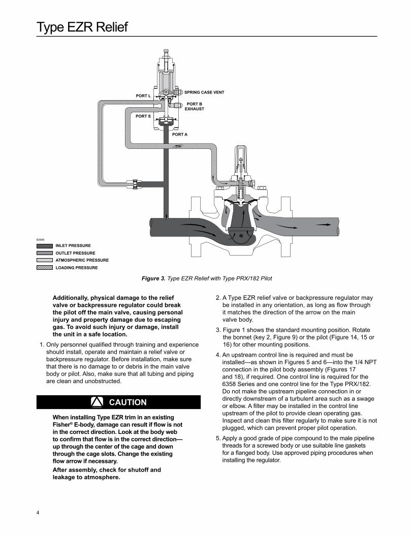
Figure 3. Type EZR Relief with Type PRX/182 Pilot
InLET PRESSURE
LOaDIng PRESSURE
OUTLET PRESSUREaTMOSPHERIC PRESSURE
Type EZR Relief with PRX 182 Pilot
E099
9
July 2008 Type EZR
TYPE 112 RESTRICTOR
PORT A
PORT B EXHAUST
PORT S
SPRING CASE VENTPORT L
INLET PRESSUREOUTLET PRESSUREATMOSPHERIC PRESSURELOADING PRESSURE
SPRIng CaSE VEnTPORT L
PORT S
PORT a
PORT B EXHaUST
E0999
Type EZR Relief
5
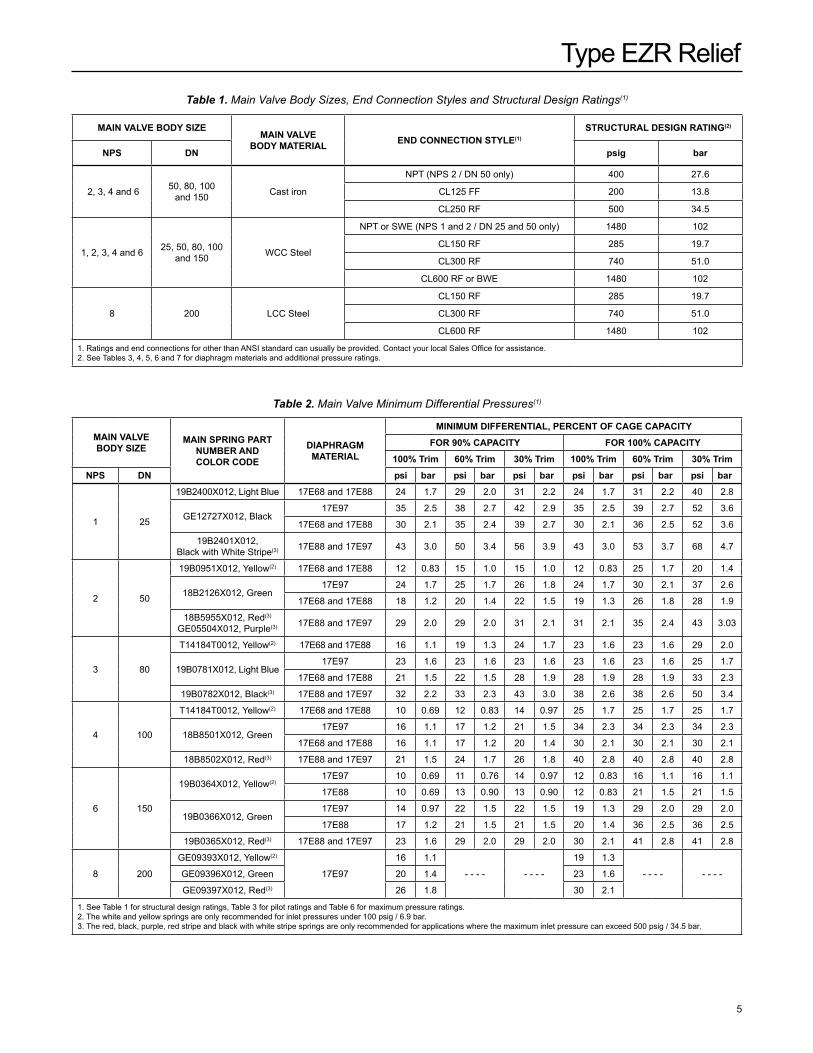
Table 1. Main Valve Body Sizes, End Connection Styles and Structural Design Ratings(1)
MaIn VaLVE BODY SIZEMaIn VaLVE
BODY MaTERIaL EnD COnnECTIOn STYLE(1)
STRUCTURaL DESIgn RaTIng(2)
nPS Dn psig bar
2, 3, 4 and 6 50, 80, 100 and 150 Cast iron
NPT (NPS 2 / DN 50 only) 400 27.6
CL125 FF 200 13.8
CL250 RF 500 34.5
1, 2, 3, 4 and 6 25, 50, 80, 100 and 150 WCC Steel
NPT or SWE (NPS 1 and 2 / DN 25 and 50 only) 1480 102
CL150 RF 285 19.7
CL300 RF 740 51.0
CL600 RF or BWE 1480 102
8 200 LCC Steel
CL150 RF 285 19.7
CL300 RF 740 51.0
CL600 RF 1480 102
1. Ratings and end connections for other than ANSI standard can usually be provided. Contact your local Sales Office for assistance.2. See Tables 3, 4, 5, 6 and 7 for diaphragm materials and additional pressure ratings.
Table 2. Main Valve Minimum Differential Pressures(1)
MaIn VaLVE BODY SIZE
MaIn SPRIng PaRT nUMBER anD COLOR CODE
DIaPHRagM MaTERIaL
MInIMUM DIFFEREnTIaL, PERCEnT OF CagE CaPaCITY
FOR 90% CaPaCITY FOR 100% CaPaCITY
100% Trim 60% Trim 30% Trim 100% Trim 60% Trim 30% Trim
nPS Dn psi bar psi bar psi bar psi bar psi bar psi bar
1 25
19B2400X012, Light Blue 17E68 and 17E88 24 1.7 29 2.0 31 2.2 24 1.7 31 2.2 40 2.8
GE12727X012, Black17E97 35 2.5 38 2.7 42 2.9 35 2.5 39 2.7 52 3.6
17E68 and 17E88 30 2.1 35 2.4 39 2.7 30 2.1 36 2.5 52 3.6
19B2401X012, Black with White Stripe(3) 17E88 and 17E97 43 3.0 50 3.4 56 3.9 43 3.0 53 3.7 68 4.7
2 50
19B0951X012, Yellow(2) 17E68 and 17E88 12 0.83 15 1.0 15 1.0 12 0.83 25 1.7 20 1.4
18B2126X012, Green17E97 24 1.7 25 1.7 26 1.8 24 1.7 30 2.1 37 2.6
17E68 and 17E88 18 1.2 20 1.4 22 1.5 19 1.3 26 1.8 28 1.9
18B5955X012, Red(3)
GE05504X012, Purple(3) 17E88 and 17E97 29 2.0 29 2.0 31 2.1 31 2.1 35 2.4 43 3.03
3 80
T14184T0012, Yellow(2) 17E68 and 17E88 16 1.1 19 1.3 24 1.7 23 1.6 23 1.6 29 2.0
19B0781X012, Light Blue17E97 23 1.6 23 1.6 23 1.6 23 1.6 23 1.6 25 1.7
17E68 and 17E88 21 1.5 22 1.5 28 1.9 28 1.9 28 1.9 33 2.3
19B0782X012, Black(3) 17E88 and 17E97 32 2.2 33 2.3 43 3.0 38 2.6 38 2.6 50 3.4
4 100
T14184T0012, Yellow(2) 17E68 and 17E88 10 0.69 12 0.83 14 0.97 25 1.7 25 1.7 25 1.7
18B8501X012, Green17E97 16 1.1 17 1.2 21 1.5 34 2.3 34 2.3 34 2.3
17E68 and 17E88 16 1.1 17 1.2 20 1.4 30 2.1 30 2.1 30 2.1
18B8502X012, Red(3) 17E88 and 17E97 21 1.5 24 1.7 26 1.8 40 2.8 40 2.8 40 2.8
6 150
19B0364X012, Yellow(2)17E97 10 0.69 11 0.76 14 0.97 12 0.83 16 1.1 16 1.1
17E88 10 0.69 13 0.90 13 0.90 12 0.83 21 1.5 21 1.5
19B0366X012, Green17E97 14 0.97 22 1.5 22 1.5 19 1.3 29 2.0 29 2.0
17E88 17 1.2 21 1.5 21 1.5 20 1.4 36 2.5 36 2.5
19B0365X012, Red(3) 17E88 and 17E97 23 1.6 29 2.0 29 2.0 30 2.1 41 2.8 41 2.8
8 200
GE09393X012, Yellow(2)
17E97
16 1.1
- - - - - - - -
19 1.3
- - - - - - - -GE09396X012, Green 20 1.4 23 1.6
GE09397X012, Red(3) 26 1.8 30 2.1
1. See Table 1 for structural design ratings, Table 3 for pilot ratings and Table 6 for maximum pressure ratings.2. The white and yellow springs are only recommended for inlet pressures under 100 psig / 6.9 bar.3. The red, black, purple, red stripe and black with white stripe springs are only recommended for applications where the maximum inlet pressure can exceed 500 psig / 34.5 bar.
Type EZR Relief
6
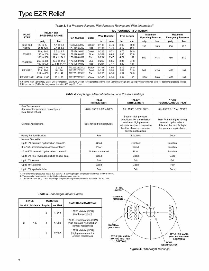
Table 3. Set Pressure Ranges, Pilot Pressure Ratings and Pilot Information(1)
PILOT TYPE
RELIEF SET PRESSURE RangE
PILOT COnTROL InFORMaTIOn
Part number ColorWire Diameter Free Length Maximum
Operating PressureMaximum
Emergency Pressurepsig bar In. mm In. mm psig bar psig bar
6358 and 6358B
20 to 4035 to 125
1.4 to 2.82.4 to 8.6
1E3925270221k748527202
YellowRed
0.1480.187
3.76 4.75
2.002.19
50.8 55.6 150 10.3 150 10.3
6358EB75 to 140130 to 200180 to 350
5.2 to 9.79.0 to 13.812.4 to 24.1
17B1261X01217B1263X01217B1264X012
GreenBlueRed
0.2250.2620.294
5.71 6.65 7.47
3.703.854.22
94.0 97.8 107 650 44.8 750 51.7
6358EBH 250 to 450400 to 600
17.3 to 31.027.6 to 41.4(2)
17B1263X01217B1264X012
BlueRed
0.2620.294
6.85 7.47
3.854.22
97.8 107
PRX/18229 to 11673 to 290217 to 609
2 to 85 to 2015 to 42
M0255220X12M0255200X12M0255190X12
BlackGoldRed
0.1570.2170.256
4.005.506.50
2.162.011.97
55.051.050.0
609 42.0 1480 102
PRX/182-AP 435 to 1160 30 to 80 M0273790X12 Clear 0.335 8.50 3.94 100 1160 80.0 1480 102
1. See the Main Valve Body Sizes, End Connections, Structural Design Ratings tables and the Main Valve Diaphragm and Spring Pressure Ratings table for additional pressure ratings. 2. Fluorocarbon (FkM) diaphragms are limited to 450 psig / 31.0 bar.
Table 4. Diaphragm Material Selection and Pressure Ratings
17E68 nITRILE (nBR)
17E97(3) nITRILE (nBR)
17E88 FLUOROCaRBOn (FKM)
Gas Temperature (for lower temperatures contact your local Sales Office)
-20 to 150°F / -28 to 66°C 0 to 150°F / -17 to 66°C 0 to 250°F / -17 to 121°C(1)
General Applications Best for cold temperatures.
Best for high pressure conditions, i.e. transmission
service or high pressure industrial service. It is also the
best for abrasive or erosive service applications.
Best for natural gas having aromatic hydrocarbons.
It is also the best for high temperature applications.
Heavy Particle Erosion Fair Excellent Good Natural Gas With: Up to 3% aromatic hydrocarbon content(2) Good Excellent Excellent
3 to 15% aromatic hydrocarbon content(2) Poor Good Excellent
15 to 50% aromatic hydrocarbon content(2) Not recommended Poor Excellent
Up to 3% H2S (hydrogen sulfide or sour gas) Good Good Good
Up to 3% ketone Fair Fair Fair
Up to 10% alcohol Good Good Fair
Up to 3% synthetic lube Fair Fair Good
1. For differential pressures above 400 psig / 27.6 bar diaphragm temperature is limited to 150°F / 66°C.2. The aromatic hydrocarbon content is based on percent volume.3. The NPS 6 / DN 150, 17E97 diaphragm will perform in gas temperatures as low as -20°F / -29°C.
Figure 4. Diaphragm Markings
11
1
1111
1
STYLE (IMPRInT)
MaTERIaL (IMPRInT)
MaTERIaL (InK MaRK)
DOME IDEnTIFICaTIOn
STYLE (InK MaRK) (MaY BE In EITHER
LOCaTIOn)STYLE (InK MaRK) (MaY BE In EITHER
LOCaTIOn)
{ { {Table 5. Diaphragm Imprint Codes
STYLE MaTERIaLDIaPHRagM MaTERIaL
Imprint Ink Mark Imprint Ink Mark
2 130
2 17E68 17E68 - Nitrile (NBR) (low temperature)
4 17E8817E88 - Fluorocarbon (FkM) (high aromatic hydrocarbon
content resistance)
5 17E9717E97 - Nitrile (NBR) (high-pressure and/or erosion resistance)
Type EZR Relief
7
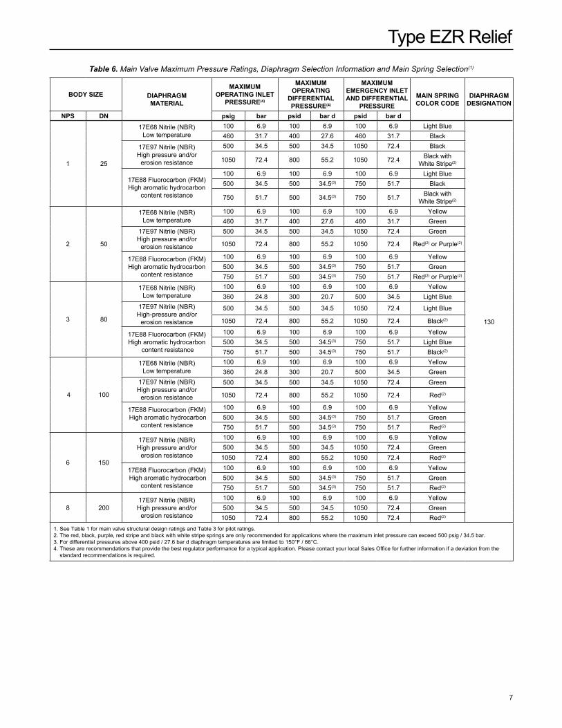
Table 6. Main Valve Maximum Pressure Ratings, Diaphragm Selection Information and Main Spring Selection(1)
BODY SIZE DIaPHRagM MaTERIaL
MaXIMUM OPERaTIng InLET
PRESSURE(4)
MaXIMUM OPERaTIng
DIFFEREnTIaL PRESSURE(4)
MaXIMUM EMERgEnCY InLET anD DIFFEREnTIaL
PRESSUREMaIn SPRIng COLOR CODE
DIaPHRagM DESIgnaTIOn
nPS Dn psig bar psid bar d psid bar d
1 25
17E68 Nitrile (NBR) Low temperature
100 6.9 100 6.9 100 6.9 Light Blue
130
460 31.7 400 27.6 460 31.7 Black
17E97 Nitrile (NBR) High pressure and/or
erosion resistance
500 34.5 500 34.5 1050 72.4 Black
1050 72.4 800 55.2 1050 72.4 Black with White Stripe(2)
17E88 Fluorocarbon (FkM) High aromatic hydrocarbon
content resistance
100 6.9 100 6.9 100 6.9 Light Blue500 34.5 500 34.5(3) 750 51.7 Black
750 51.7 500 34.5(3) 750 51.7 Black with White Stripe(2)
2 50
17E68 Nitrile (NBR) Low temperature
100 6.9 100 6.9 100 6.9 Yellow 460 31.7 400 27.6 460 31.7 Green
17E97 Nitrile (NBR) High pressure and/or
erosion resistance
500 34.5 500 34.5 1050 72.4 Green
1050 72.4 800 55.2 1050 72.4 Red(2) or Purple(2)
17E88 Fluorocarbon (FkM) High aromatic hydrocarbon
content resistance
100 6.9 100 6.9 100 6.9 Yellow500 34.5 500 34.5(3) 750 51.7 Green750 51.7 500 34.5(3) 750 51.7 Red(2) or Purple(2)
3 80
17E68 Nitrile (NBR) Low temperature
100 6.9 100 6.9 100 6.9 Yellow360 24.8 300 20.7 500 34.5 Light Blue
17E97 Nitrile (NBR) High-pressure and/or
erosion resistance
500 34.5 500 34.5 1050 72.4 Light Blue
1050 72.4 800 55.2 1050 72.4 Black(2)
17E88 Fluorocarbon (FkM) High aromatic hydrocarbon
content resistance
100 6.9 100 6.9 100 6.9 Yellow500 34.5 500 34.5(3) 750 51.7 Light Blue750 51.7 500 34.5(3) 750 51.7 Black(2)
4 100
17E68 Nitrile (NBR)Low temperature
100 6.9 100 6.9 100 6.9 Yellow 360 24.8 300 20.7 500 34.5 Green
17E97 Nitrile (NBR)High pressure and/or
erosion resistance
500 34.5 500 34.5 1050 72.4 Green
1050 72.4 800 55.2 1050 72.4 Red(2)
17E88 Fluorocarbon (FkM) High aromatic hydrocarbon
content resistance
100 6.9 100 6.9 100 6.9 Yellow500 34.5 500 34.5(3) 750 51.7 Green750 51.7 500 34.5(3) 750 51.7 Red(2)
6 150
17E97 Nitrile (NBR)High pressure and/or
erosion resistance
100 6.9 100 6.9 100 6.9 Yellow500 34.5 500 34.5 1050 72.4 Green
1050 72.4 800 55.2 1050 72.4 Red(2)
17E88 Fluorocarbon (FkM) High aromatic hydrocarbon
content resistance
100 6.9 100 6.9 100 6.9 Yellow500 34.5 500 34.5(3) 750 51.7 Green750 51.7 500 34.5(3) 750 51.7 Red(2)
8 20017E97 Nitrile (NBR)
High pressure and/or erosion resistance
100 6.9 100 6.9 100 6.9 Yellow 500 34.5 500 34.5 1050 72.4 Green
1050 72.4 800 55.2 1050 72.4 Red(2)
1. See Table 1 for main valve structural design ratings and Table 3 for pilot ratings.2. The red, black, purple, red stripe and black with white stripe springs are only recommended for applications where the maximum inlet pressure can exceed 500 psig / 34.5 bar.3. For differential pressures above 400 psid / 27.6 bar d diaphragm temperatures are limited to 150°F / 66°C.4. These are recommendations that provide the best regulator performance for a typical application. Please contact your local Sales Office for further information if a deviation from the
standard recommendations is required.
Type EZR Relief
8
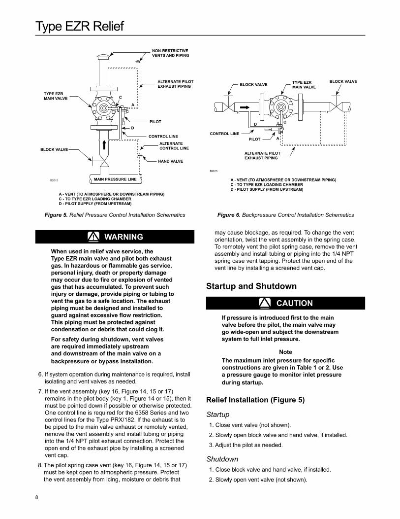
Figure 5. Relief Pressure Control Installation Schematics
B2615
B2615
BLOCK VaLVE TYPE EZR MaIn VaLVE
BLOCK VaLVE
COnTROL LInEPILOT
aLTERnaTE PILOT EXHaUST PIPIng
Figure 6. Backpressure Control Installation Schematics
nOn-RESTRICTIVE VEnTS anD PIPIng
aLTERnaTE PILOT EXHaUST PIPIng
PILOT
COnTROL LInE
aLTERnaTE COnTROL LInE
HanD VaLVE
MaIn PRESSURE LInE
BLOCK VaLVE
TYPE EZR MaIn VaLVE C
a
DCD
a
a - VEnT (TO aTMOSPHERE OR DOWnSTREaM PIPIng)C - TO TYPE EZR LOaDIng CHaMBERD - PILOT SUPPLY (FROM UPSTREaM)
a - VEnT (TO aTMOSPHERE OR DOWnSTREaM PIPIng)C - TO TYPE EZR LOaDIng CHaMBERD - PILOT SUPPLY (FROM UPSTREaM)
! WaRnIngWhen used in relief valve service, the Type EZR main valve and pilot both exhaust gas. In hazardous or flammable gas service, personal injury, death or property damage may occur due to fire or explosion of vented gas that has accumulated. To prevent such injury or damage, provide piping or tubing to vent the gas to a safe location. The exhaust piping must be designed and installed to guard against excessive flow restriction. This piping must be protected against condensation or debris that could clog it.For safety during shutdown, vent valves are required immediately upstream and downstream of the main valve on a backpressure or bypass installation.
6. If system operation during maintenance is required, install isolating and vent valves as needed.
7. If the vent assembly (key 16, Figure 14, 15 or 17) remains in the pilot body (key 1, Figure 14 or 15), then it must be pointed down if possible or otherwise protected. One control line is required for the 6358 Series and two control lines for the Type PRX/182. If the exhaust is to be piped to the main valve exhaust or remotely vented, remove the vent assembly and install tubing or piping into the 1/4 NPT pilot exhaust connection. Protect the open end of the exhaust pipe by installing a screened vent cap.
8. The pilot spring case vent (key 16, Figure 14, 15 or 17) must be kept open to atmospheric pressure. Protect the vent assembly from icing, moisture or debris that
may cause blockage, as required. To change the vent orientation, twist the vent assembly in the spring case. To remotely vent the pilot spring case, remove the vent assembly and install tubing or piping into the 1/4 NPT spring case vent tapping. Protect the open end of the vent line by installing a screened vent cap.
Startup and Shutdown
CaUTIOnIf pressure is introduced first to the main valve before the pilot, the main valve may go wide-open and subject the downstream system to full inlet pressure.
noteThe maximum inlet pressure for specific constructions are given in Table 1 or 2. Use a pressure gauge to monitor inlet pressure during startup.
Relief Installation (Figure 5)
Startup 1. Close vent valve (not shown).
2. Slowly open block valve and hand valve, if installed.
3. Adjust the pilot as needed.
Shutdown 1. Close block valve and hand valve, if installed.
2. Slowly open vent valve (not shown).
Type EZR Relief
9
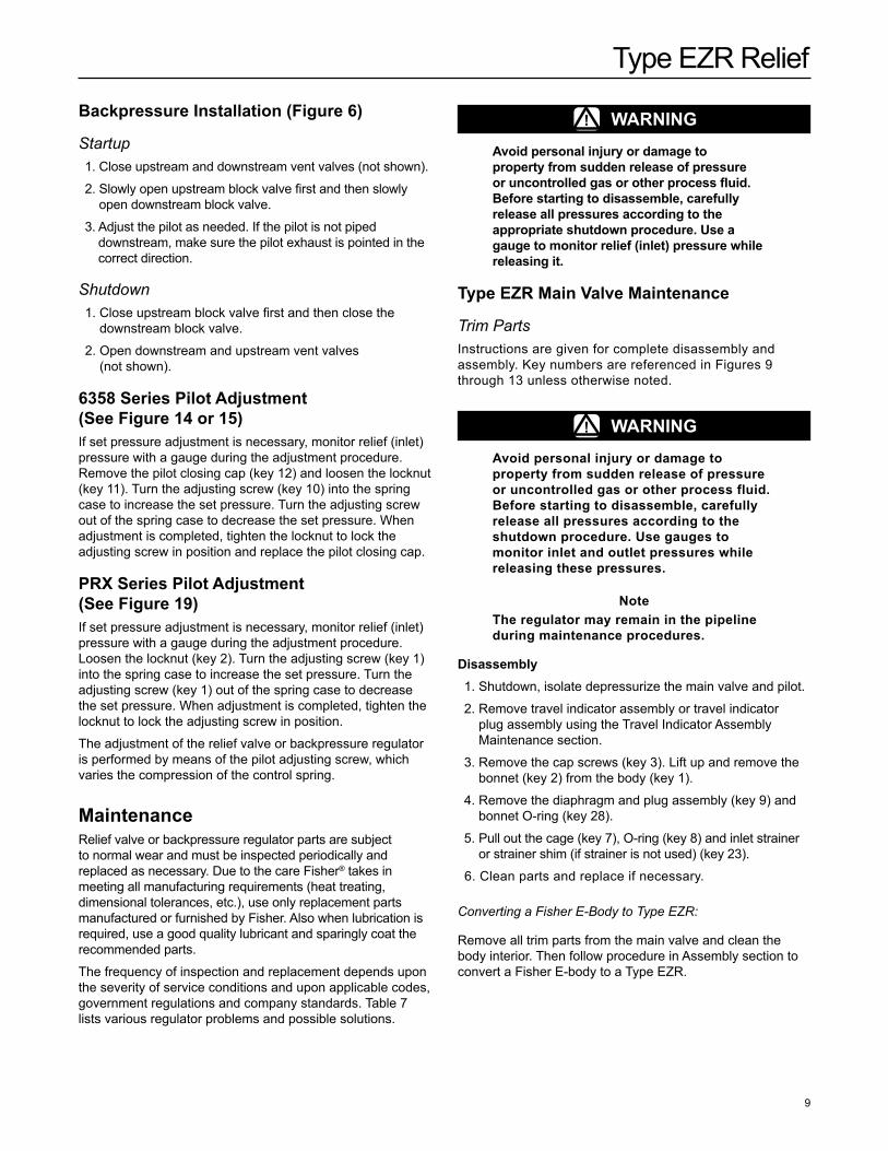
Backpressure Installation (Figure 6)
Startup 1. Close upstream and downstream vent valves (not shown).
2. Slowly open upstream block valve first and then slowly open downstream block valve.
3. Adjust the pilot as needed. If the pilot is not piped downstream, make sure the pilot exhaust is pointed in the correct direction.
Shutdown 1. Close upstream block valve first and then close the
downstream block valve.
2. Open downstream and upstream vent valves (not shown).
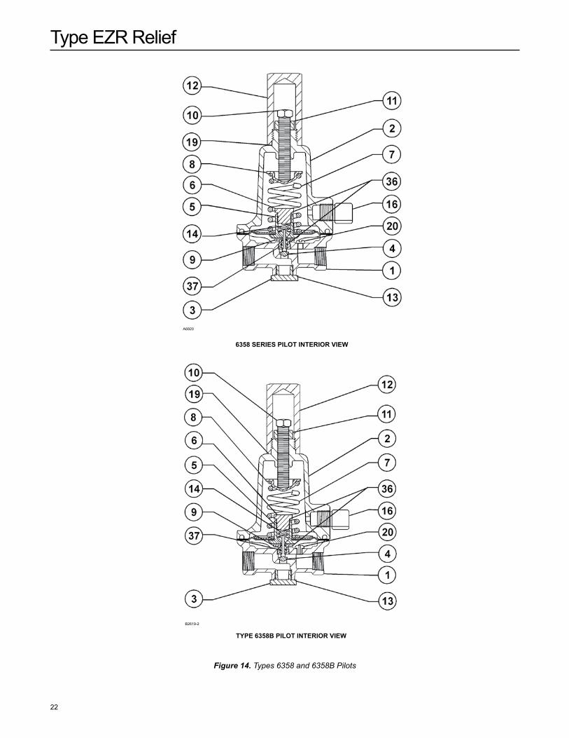
6358 Series Pilot adjustment (See Figure 14 or 15)If set pressure adjustment is necessary, monitor relief (inlet) pressure with a gauge during the adjustment procedure. Remove the pilot closing cap (key 12) and loosen the locknut (key 11). Turn the adjusting screw (key 10) into the spring case to increase the set pressure. Turn the adjusting screw out of the spring case to decrease the set pressure. When adjustment is completed, tighten the locknut to lock the adjusting screw in position and replace the pilot closing cap.
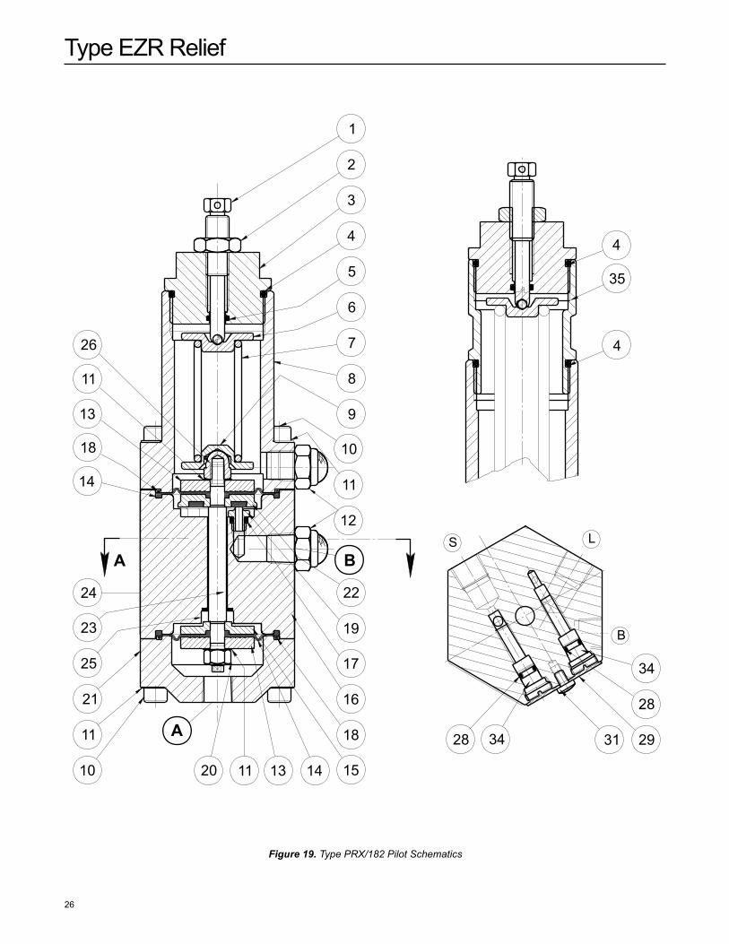
PRX Series Pilot adjustment (See Figure 19)If set pressure adjustment is necessary, monitor relief (inlet) pressure with a gauge during the adjustment procedure. Loosen the locknut (key 2). Turn the adjusting screw (key 1) into the spring case to increase the set pressure. Turn the adjusting screw (key 1) out of the spring case to decrease the set pressure. When adjustment is completed, tighten the locknut to lock the adjusting screw in position.
The adjustment of the relief valve or backpressure regulator is performed by means of the pilot adjusting screw, which varies the compression of the control spring.
MaintenanceRelief valve or backpressure regulator parts are subject to normal wear and must be inspected periodically and replaced as necessary. Due to the care Fisher® takes in meeting all manufacturing requirements (heat treating, dimensional tolerances, etc.), use only replacement parts manufactured or furnished by Fisher. Also when lubrication is required, use a good quality lubricant and sparingly coat the recommended parts.
The frequency of inspection and replacement depends upon the severity of service conditions and upon applicable codes, government regulations and company standards. Table 7 lists various regulator problems and possible solutions.
! WaRnIngavoid personal injury or damage to property from sudden release of pressure or uncontrolled gas or other process fluid. Before starting to disassemble, carefully release all pressures according to the appropriate shutdown procedure. Use a gauge to monitor relief (inlet) pressure while releasing it.
Type EZR Main Valve Maintenance
Trim PartsInstructions are given for complete disassembly and assembly. key numbers are referenced in Figures 9 through 13 unless otherwise noted.
! WaRnIngavoid personal injury or damage to property from sudden release of pressure or uncontrolled gas or other process fluid. Before starting to disassemble, carefully release all pressures according to the shutdown procedure. Use gauges to monitor inlet and outlet pressures while releasing these pressures.
noteThe regulator may remain in the pipeline during maintenance procedures.
Disassembly 1. Shutdown, isolate depressurize the main valve and pilot.
2. Remove travel indicator assembly or travel indicator plug assembly using the Travel Indicator Assembly Maintenance section.
3. Remove the cap screws (key 3). Lift up and remove the bonnet (key 2) from the body (key 1).
4. Remove the diaphragm and plug assembly (key 9) and bonnet O-ring (key 28).
5. Pull out the cage (key 7), O-ring (key 8) and inlet strainer or strainer shim (if strainer is not used) (key 23).
6. Clean parts and replace if necessary.
Converting a Fisher E-Body to Type EZR:
Remove all trim parts from the main valve and clean the body interior. Then follow procedure in Assembly section to convert a Fisher E-body to a Type EZR.
Type EZR Relief
10
CaUTIOnWhen installing a Type EZR trim package make sure flow is up through the center of the cage and down through the cage slots. In some cases, correct flow path is achieved by removing the body from the line and turning it around. If this is done, change the flow arrow to indicate the correct direction. Damage may result if flow is not in the correct direction. after assembly, check the regulator for shutoff and leakage to atmosphere.
assembly 1. Install the inlet strainer or shim (key 23) into the body
(key 1).
noteFor installation in a vertical orientation, lubricant can be applied to the bottom of the inlet strainer or shim (key 23) to help hold parts in place while the cage assembly is installed.
2. Lightly lubricate and install the cage O-ring (key 8).
3. Apply lubricant lightly to all O-rings or the mating part before installing them.
4. Install the cage (key 7) and lightly lubricate and install the bonnet O-ring (key 28).
noteFor the nPS 6 / Dn 150, secure the cage (key 7) to the restrictor plate (key 71) using the cap screws (key 126), using a torque of 10 to 12 ft-lbs / 14 to 16 N•m.
5. Lubricate the top and bottom of the outer edge (bead area) of the diaphragm and place diaphragm and plug assembly (key 9) on the cage (key 7) making sure the bead is in the cage groove. Lubricate the top plug (key 5) recess.
6. Prior to installing the travel indicator or travel indicator plug, install the bonnet (key 2) in proper orientation.
CaUTIOnMake sure to use a Type EZR bonnet. The Type EZR bonnet is not interchangeable with other Fisher® E-body bonnets. Installing an improper bonnet can result in stem assembly breakage and unit failure. The bonnet can be identified by the Type EZR markings on the top.
7. Lubricate cap screws (key 3) and secure the bonnet (key 2), using an even crisscross pattern. It may be necessary to push down on the bonnet to start the cap screws. Tighten cap screws to the proper torque (see Table 8).
8. Lightly lubricate the travel indicator assembly threads and install the indicator fitting (key 19) into the bonnet (key 2, Figure 14), tighten to the proper torque (see Table 8).
Diaphragm and Plug assembly MaintenanceThe diaphragm and plug assembly can be replaced as a single unit (a diaphragm cartridge) or individual components within the assembly can be replaced. When replacing individual components, inspect each component for damage
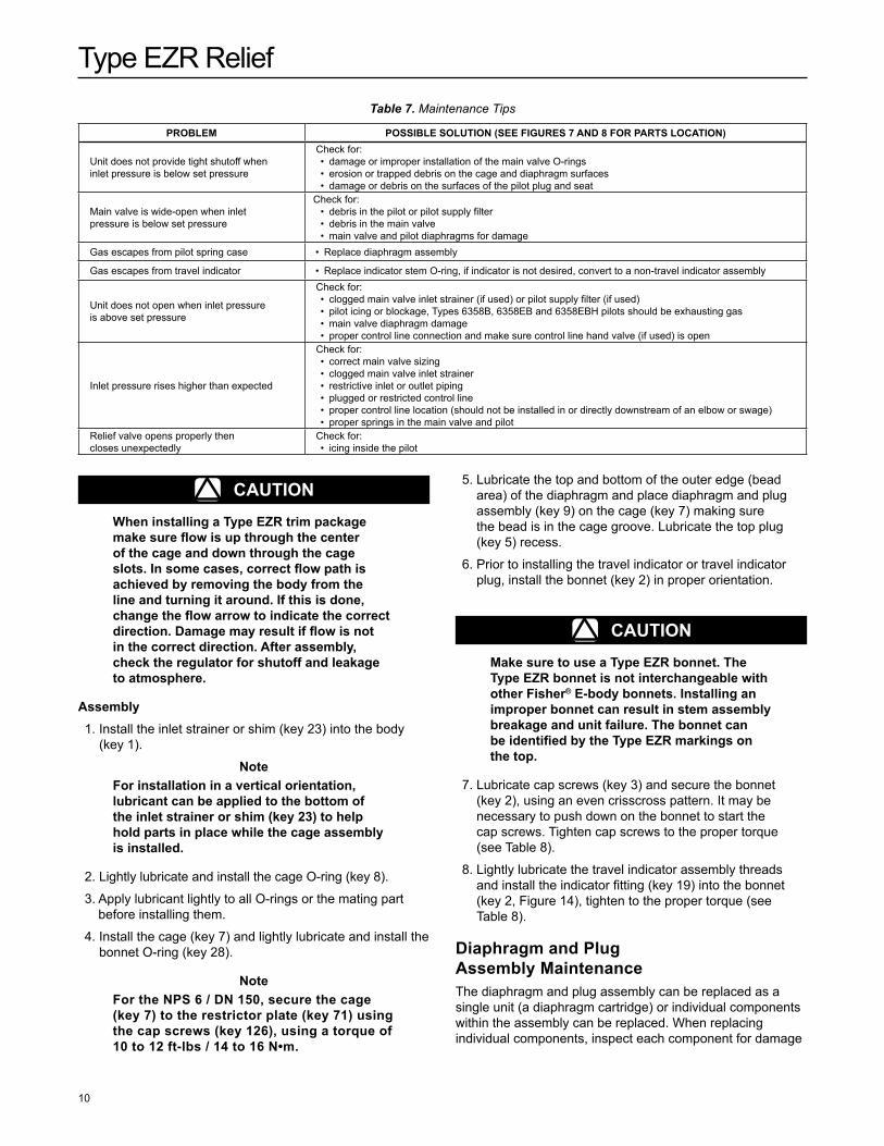
PROBLEM POSSIBLE SOLUTIOn (SEE FIgURES 7 anD 8 FOR PaRTS LOCaTIOn)
Unit does not provide tight shutoff when inlet pressure is below set pressure
Check for: • damage or improper installation of the main valve O-rings • erosion or trapped debris on the cage and diaphragm surfaces • damage or debris on the surfaces of the pilot plug and seat
Main valve is wide-open when inlet pressure is below set pressure
Check for: • debris in the pilot or pilot supply filter • debris in the main valve • main valve and pilot diaphragms for damage
Gas escapes from pilot spring case • Replace diaphragm assembly
Gas escapes from travel indicator • Replace indicator stem O-ring, if indicator is not desired, convert to a non-travel indicator assembly
Unit does not open when inlet pressure is above set pressure
Check for: • clogged main valve inlet strainer (if used) or pilot supply filter (if used) • pilot icing or blockage, Types 6358B, 6358EB and 6358EBH pilots should be exhausting gas • main valve diaphragm damage • proper control line connection and make sure control line hand valve (if used) is open
Inlet pressure rises higher than expected
Check for: • correct main valve sizing • clogged main valve inlet strainer • restrictive inlet or outlet piping • plugged or restricted control line • proper control line location (should not be installed in or directly downstream of an elbow or swage) • proper springs in the main valve and pilot
Relief valve opens properly then closes unexpectedly
Check for: • icing inside the pilot
Table 7. Maintenance Tips
Type EZR Relief
11
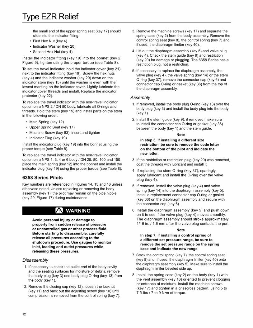
and wear and replace parts as needed. key numbers for the following assembly and disassembly procedure are referenced in Figures 7 and 9.
1. Place a screwdriver or similar tool through the hole in the top plug (key 5).
2. Remove the flanged locknut (key 13) from the bottom plug (key 11). This loosens the entire assembly.
noteOn nPS 1 / Dn 25 body, remove the socket head screw (key 129) and lock washer (key 130) from the bottom plug.
3. Remove the bottom plug (key 11) and the bottom plug O-ring (key 10).
4. Remove the diaphragm (key 9).
5. Remove the top plug O-rings (keys 14 and 70).
6. Check all components for damage or wear and replace as necessary.
7. When reassembling, be sure to lubricate all O-rings before installing.
8. Hold the top plug (key 5). Place the parts on the top plug in the following order.
• O-ring (key 14) • O-ring (key 70) • Diaphragm (key 9) • O-ring (key 10) • Bottom Plug (key 11) • Flanged Locknut (key 13)
9. Reassemble in the reverse order. Tighten flange locknut (key 13) to the proper torque (see Table 8).
Travel Indicator assembly MaintenanceTravel indicator assembly key numbers are referenced in Figures 8, 9 and 13. The indicator assembly can be removed and installed without removing the bonnet (key 2) from the body (key 1). Travel indicator maintenance is performed for two reasons:
a. When damaged or worn parts need replacing. b. When travel indicator is removed and replaced with a
travel indicator plug assembly.
! WaRnIngavoid personal injury or damage to property from sudden release of pressure or uncontrolled gas or other process fluid. Before starting to disassemble, carefully release all pressures according to the shutdown procedure. Use gauges to monitor inlet, loading and outlet pressures while releasing these pressures.
1. Remove the indicator protector (key 22, Figure 9) and indicator cover (key 21).
2. Remove the first hex nut (key 4) and the indicator washer (key 20).
3. Unscrew the second hex nut (key 4) to the top of the indicator stem (key 15). Do not remove.
4. Use a wrench to remove indicator fitting (key 19).
5. Lift out travel indicator assembly. If replacing travel indicator with travel indicator plug, skip to step 9.
6. Compress the main spring (key 12). Remove the second hex nut (key 4). Parts will separate easily when the hex nut is removed.
7. Slide the indicator stem (key 15) out of the indicator fitting (key 19). The main spring (key 12) and upper spring seat (key 17) will be free.
8. If necessary, use the indicator stem (key 15) to pry the backup rings (key 16) and O-ring (key 18) out of the indicator fitting (key 19).
9. Check the indicator fitting O-ring (key 6). Lubricate and replace if necessary.
10. To replace travel indicator parts, lubricate all O-rings, backup rings and threads. To reassemble, hold the indicator stem (key 15) and place the parts on the stem in the following order:
• Washer (key 79 for NPS 6 / DN 150 size only) • Main Spring (key 12), small end first • Upper Spring Seat (key 17), make sure to place the large
end toward the spring • First Backup Ring (key 16) • O-ring (key 18) • Second Backup Ring (key 16) • Indicator Fitting (key 19), the backup rings (key 16) and
O-ring (key 18) should slide into the indicator fitting and
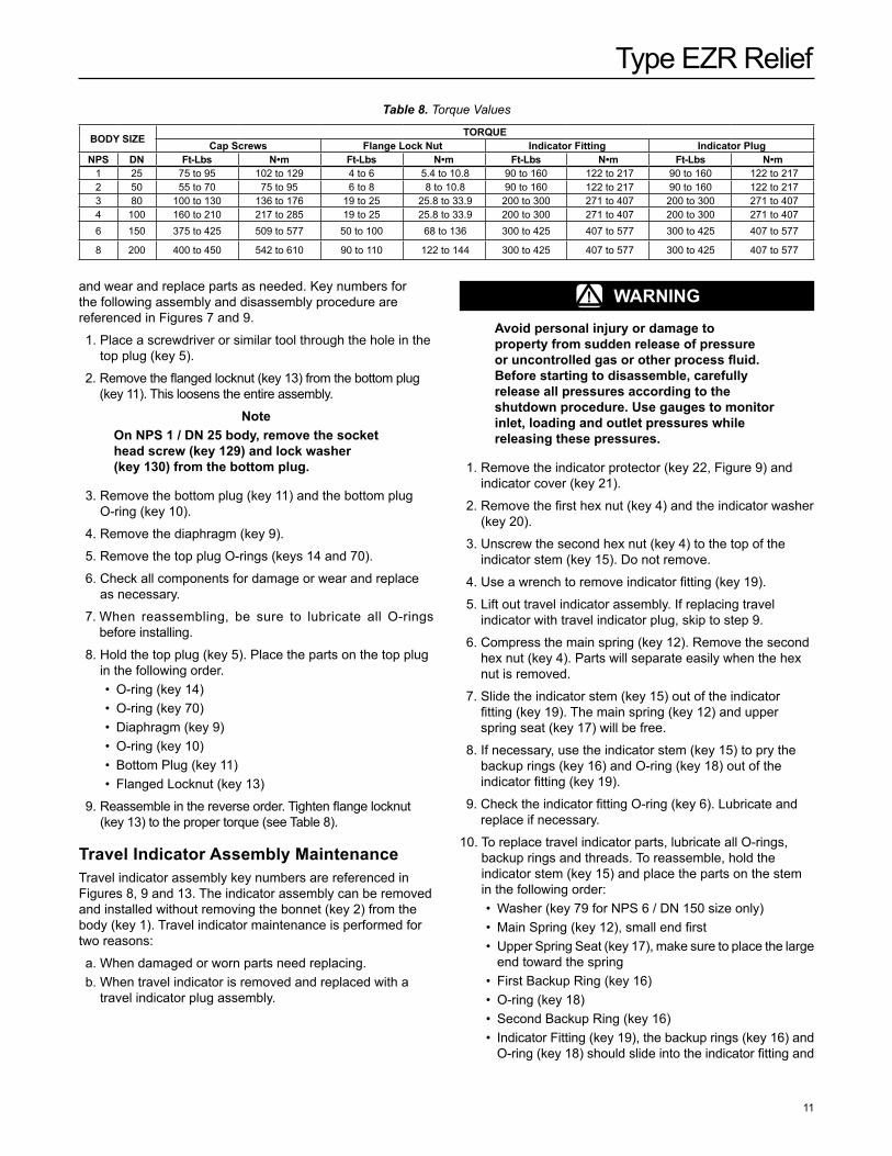
BODY SIZE TORQUECap Screws Flange Lock nut Indicator Fitting Indicator Plug
nPS Dn Ft-Lbs N•m Ft-Lbs N•m Ft-Lbs N•m Ft-Lbs N•m1 25 75 to 95 102 to 129 4 to 6 5.4 to 10.8 90 to 160 122 to 217 90 to 160 122 to 217 2 50 55 to 70 75 to 95 6 to 8 8 to 10.8 90 to 160 122 to 217 90 to 160 122 to 217 3 80 100 to 130 136 to 176 19 to 25 25.8 to 33.9 200 to 300 271 to 407 200 to 300 271 to 407 4 100 160 to 210 217 to 285 19 to 25 25.8 to 33.9 200 to 300 271 to 407 200 to 300 271 to 407 6 150 375 to 425 509 to 577 50 to 100 68 to 136 300 to 425 407 to 577 300 to 425 407 to 577
8 200 400 to 450 542 to 610 90 to 110 122 to 144 300 to 425 407 to 577 300 to 425 407 to 577
Table 8. Torque Values
Type EZR Relief
12
the small end of the upper spring seat (key 17) should slide into the indicator fitting.
• First Hex Nut (key 4) • Indicator Washer (key 20) • Second Hex Nut (key 4)
Install the indicator fitting (key 19) into the bonnet (key 2, Figure 9), tighten using the proper torque (see Table 8).
To set the travel indicator, hold the indicator cover (key 21) next to the indicator fitting (key 19). Screw the hex nuts (key 4) and the indicator washer (key 20) down on the indicator stem (key 15) until the washer is even with the lowest marking on the indicator cover. Lightly lubricate the indicator cover threads and install. Replace the indicator protector (key 22).
To replace the travel indicator with the non-travel indicator option on a NPS 2 / DN 50 body, lubricate all O-rings and threads. Hold the stem (key 15) and install parts on the stem in the following order:
• Main Spring (key 12) • Upper Spring Seat (key 17) • Machine Screw (key 83), insert and tighten • Indicator Plug (key 19)
Install the indicator plug (key 19) into the bonnet using the proper torque (see Table 8).
To replace the travel indicator with the non-travel indicator option on a NPS 1, 3, 4 or 6 body / DN 25, 80, 100 and 150 place the main spring (key 12) into the bonnet and install the indicator plug (key 19) using the proper torque (see Table 8).
6358 Series Pilotskey numbers are referenced in Figures 14, 15 and 16 unless otherwise noted. Unless replacing or removing the body assembly (key 1), the pilot may remain on the pipe nipple (key 29, Figure 17) during maintenance.
! WaRnIngavoid personal injury or damage to property from sudden release of pressure or uncontrolled gas or other process fluid. Before starting to disassemble, carefully release all pressures according to the shutdown procedure. Use gauges to monitor inlet, loading and outlet pressures while releasing these pressures.
Disassembly 1. If necessary to check the outlet end of the body cavity
and the seating surfaces for moisture or debris, remove the body plug (key 3) and body plug O-ring (key 13) from the body (key 1).
2. Remove the closing cap (key 12), loosen the locknut (key 11) and back out the adjusting screw (key 10) until compression is removed from the control spring (key 7).
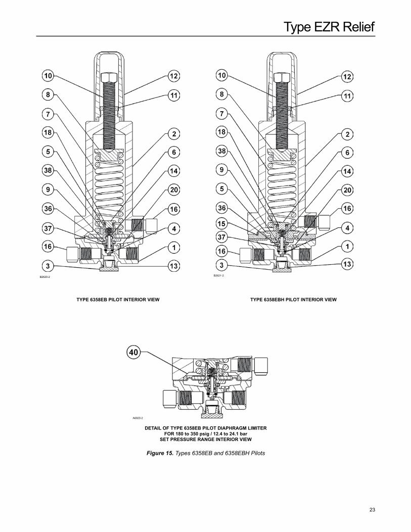
3. Remove the machine screws (key 17) and separate the spring case (key 2) from the body assembly. Remove the control spring seat (key 8), the control spring (key 7) and, if used, the diaphragm limiter (key 40).
4. Lift out the diaphragm assembly (key 5) and valve plug (key 4). Check the stem guide (key 9) and restriction (key 20) for damage or plugging. The 6358 Series has a restriction plug, not a restriction.
5. If necessary to replace the diaphragm assembly, the valve plug (key 4), the valve spring (key 14) or the stem O-ring (key 37), remove the connector cap (key 6) and connector cap O-ring or gasket (key 36) from the top of the diaphragm assembly.
Assembly 1. If removed, install the body plug O-ring (key 13) over the
body plug (key 3) and install the body plug into the body (key 1).
2. Install the stem guide (key 9), if removed make sure to install the connector cap O-ring or gasket (key 36) between the body (key 1) and the stem guide.
noteIn step 3, if installing a different size restriction, be sure to remove the code letter on the bottom of the pilot and indicate the new letter.
3. If the restriction or restriction plug (key 20) was removed, coat the threads with lubricant and install it.
4. If replacing the stem O-ring (key 37), sparingly apply lubricant and install the O-ring over the valve plug (key 4).
5. If removed, install the valve plug (key 4) and valve spring (key 14) into the diaphragm assembly (key 5). Install a replacement connector cap O-ring or gasket (key 36) on the diaphragm assembly and secure with the connector cap (key 6).
6. Install the diaphragm assembly (key 5) and push down on it to see if the valve plug (key 4) moves smoothly. The diaphragm assembly should stroke approximately 1/16 in. / 1.6 mm after the valve plug contacts the port.
noteIn step 7, if installing a control spring of a different set pressure range, be sure to remove the set pressure range on the spring case and indicate the new range.
7. Stack the control spring (key 7), the control spring seat (key 8) and, if used, the diaphragm limiter (key 40) onto the diaphragm assembly (key 5). Make sure to install the diaphragm limiter beveled side up.
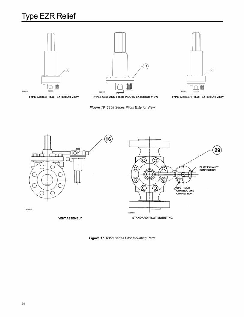
8. Install the spring case (key 2) on the body (key 1) with the vent assembly (key 16) oriented to prevent clogging or entrance of moisture. Install the machine screws (key 17) and tighten in a crisscross pattern, using 5 to 7 ft-lbs / 7 to 9 N•m of torque.
Type EZR Relief
13
9. Replace the closing cap gasket (key 19) if necessary install the closing cap (key 12). When all maintenance is complete, refer to the Startup and Shutdown section to put the relief valve or backpressure regulator into operation and adjust the pressure setting.
Type PRX/182 PilotA Type PRX/182 pilot has the ability to handle a wide range of setpoints from 29 to 1160 psig / 2.0 to 80.0 bar.
Type PRX/182 Pilot Maintenance
CaUTIOnalways remove spring tension before performing maintenance on this unit. To remove spring compression, loosen locknut (key 2, Figure 19) and back out adjusting screw (key 1) until compression is removed from the spring (key 7).
noteapply an anti-seize compound to the adjusting screw threads and other areas as needed.
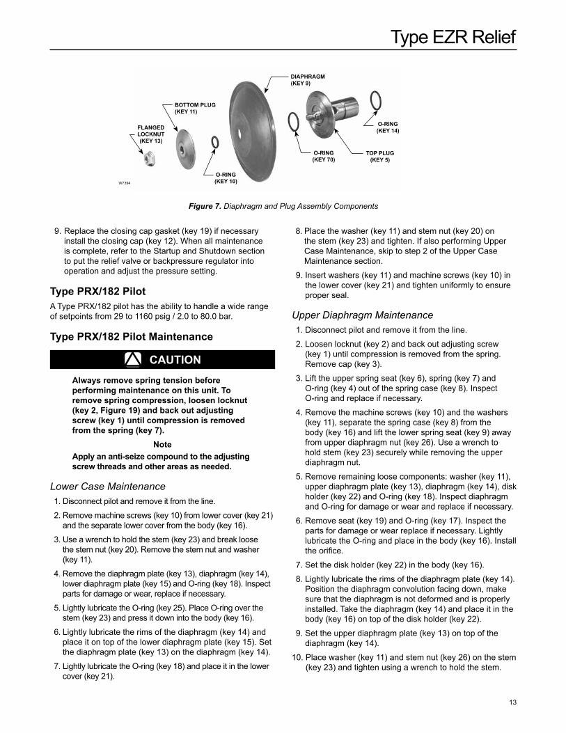
Lower Case Maintenance 1. Disconnect pilot and remove it from the line.
2. Remove machine screws (key 10) from lower cover (key 21) and the separate lower cover from the body (key 16).
3. Use a wrench to hold the stem (key 23) and break loose the stem nut (key 20). Remove the stem nut and washer (key 11).
4. Remove the diaphragm plate (key 13), diaphragm (key 14), lower diaphragm plate (key 15) and O-ring (key 18). Inspect parts for damage or wear, replace if necessary.
5. Lightly lubricate the O-ring (key 25). Place O-ring over the stem (key 23) and press it down into the body (key 16).
6. Lightly lubricate the rims of the diaphragm (key 14) and place it on top of the lower diaphragm plate (key 15). Set the diaphragm plate (key 13) on the diaphragm (key 14).
7. Lightly lubricate the O-ring (key 18) and place it in the lower cover (key 21).
8. Place the washer (key 11) and stem nut (key 20) on the stem (key 23) and tighten. If also performing Upper Case Maintenance, skip to step 2 of the Upper Case Maintenance section.
9. Insert washers (key 11) and machine screws (key 10) in the lower cover (key 21) and tighten uniformly to ensure proper seal.
Upper Diaphragm Maintenance 1. Disconnect pilot and remove it from the line.
2. Loosen locknut (key 2) and back out adjusting screw (key 1) until compression is removed from the spring. Remove cap (key 3).
3. Lift the upper spring seat (key 6), spring (key 7) and O-ring (key 4) out of the spring case (key 8). Inspect O-ring and replace if necessary.
4. Remove the machine screws (key 10) and the washers (key 11), separate the spring case (key 8) from the body (key 16) and lift the lower spring seat (key 9) away from upper diaphragm nut (key 26). Use a wrench to hold stem (key 23) securely while removing the upper diaphragm nut.
5. Remove remaining loose components: washer (key 11), upper diaphragm plate (key 13), diaphragm (key 14), disk holder (key 22) and O-ring (key 18). Inspect diaphragm and O-ring for damage or wear and replace if necessary.
6. Remove seat (key 19) and O-ring (key 17). Inspect the parts for damage or wear replace if necessary. Lightly lubricate the O-ring and place in the body (key 16). Install the orifice.
7. Set the disk holder (key 22) in the body (key 16).
8. Lightly lubricate the rims of the diaphragm plate (key 14). Position the diaphragm convolution facing down, make sure that the diaphragm is not deformed and is properly installed. Take the diaphragm (key 14) and place it in the body (key 16) on top of the disk holder (key 22).
9. Set the upper diaphragm plate (key 13) on top of the diaphragm (key 14).
10. Place washer (key 11) and stem nut (key 26) on the stem (key 23) and tighten using a wrench to hold the stem.
W7394
FLangED LOCKnUT(KEY 13)
BOTTOM PLUg (KEY 11)
DIaPHRagM (KEY 9)
O-RIng(KEY 14)
TOP PLUg (KEY 5)
O-RIng (KEY 70)
O-RIng (KEY 10)
Figure 7. Diaphragm and Plug Assembly Components
Type EZR Relief
14
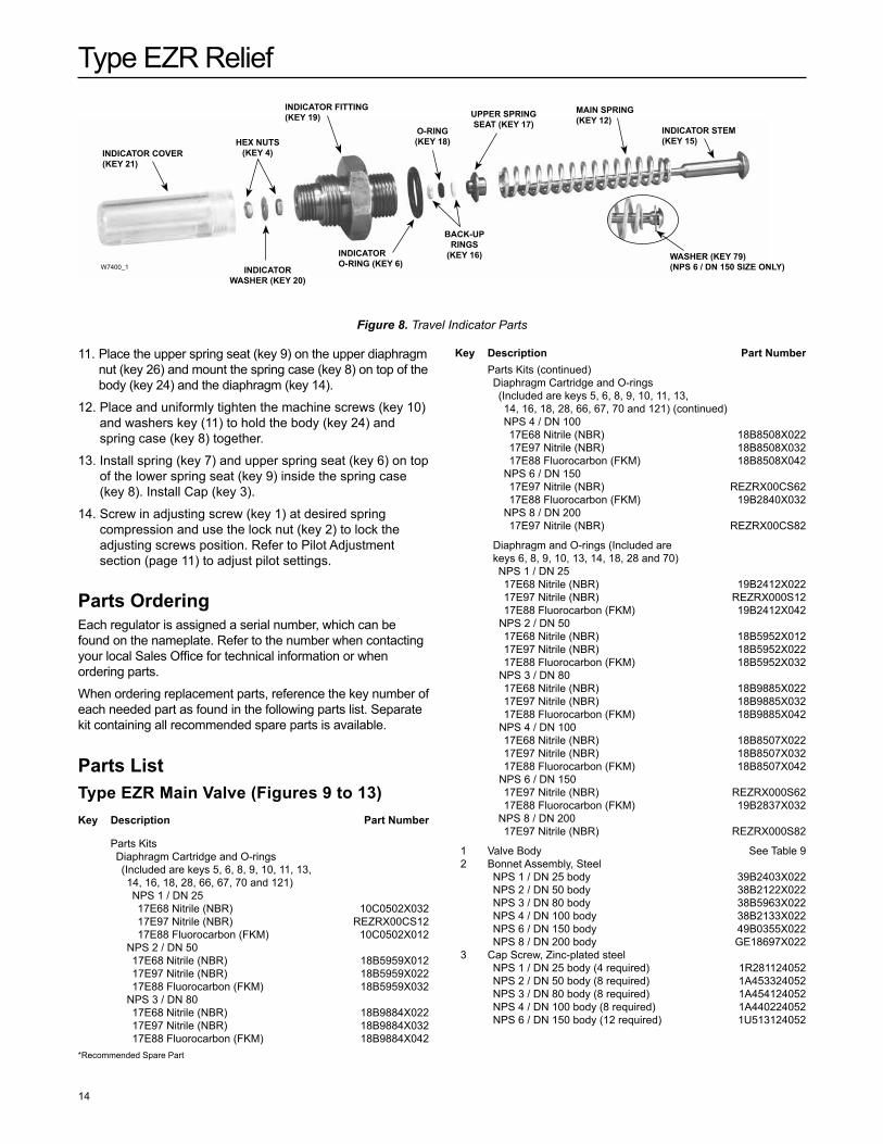
InDICaTOR COVER (KEY 21)
HEX nUTS(KEY 4)
InDICaTOR FITTIng(KEY 19)
O-RIng(KEY 18)
UPPER SPRIng SEaT (KEY 17)
MaIn SPRIng(KEY 12)
InDICaTOR STEM(KEY 15)
WaSHER (KEY 79) (nPS 6 / Dn 150 SIZE OnLY)
BaCK-UP RIngS
(KEY 16)InDICaTOR O-RIng (KEY 6)
InDICaTOR WaSHER (KEY 20)
W7400_1
Figure 8. Travel Indicator Parts
11. Place the upper spring seat (key 9) on the upper diaphragm nut (key 26) and mount the spring case (key 8) on top of the body (key 24) and the diaphragm (key 14).
12. Place and uniformly tighten the machine screws (key 10) and washers key (11) to hold the body (key 24) and spring case (key 8) together.
13. Install spring (key 7) and upper spring seat (key 6) on top of the lower spring seat (key 9) inside the spring case (key 8). Install Cap (key 3).
14. Screw in adjusting screw (key 1) at desired spring compression and use the lock nut (key 2) to lock the adjusting screws position. Refer to Pilot Adjustment section (page 11) to adjust pilot settings.
Parts OrderingEach regulator is assigned a serial number, which can be found on the nameplate. Refer to the number when contacting your local Sales Office for technical information or when ordering parts.
When ordering replacement parts, reference the key number of each needed part as found in the following parts list. Separate kit containing all recommended spare parts is available.
Parts ListType EZR Main Valve (Figures 9 to 13)Key Description Part number
Parts kits Diaphragm Cartridge and O-rings
(Included are keys 5, 6, 8, 9, 10, 11, 13, 14, 16, 18, 28, 66, 67, 70 and 121)
NPS 1 / DN 25 17E68 Nitrile (NBR) 10C0502X032 17E97 Nitrile (NBR) REZRX00CS12 17E88 Fluorocarbon (FkM) 10C0502X012 NPS 2 / DN 50 17E68 Nitrile (NBR) 18B5959X012 17E97 Nitrile (NBR) 18B5959X022 17E88 Fluorocarbon (FkM) 18B5959X032 NPS 3 / DN 80 17E68 Nitrile (NBR) 18B9884X022 17E97 Nitrile (NBR) 18B9884X032 17E88 Fluorocarbon (FkM) 18B9884X042
Parts kits (continued) Diaphragm Cartridge and O-rings
(Included are keys 5, 6, 8, 9, 10, 11, 13, 14, 16, 18, 28, 66, 67, 70 and 121) (continued)
NPS 4 / DN 100 17E68 Nitrile (NBR) 18B8508X022 17E97 Nitrile (NBR) 18B8508X032 17E88 Fluorocarbon (FkM) 18B8508X042 NPS 6 / DN 150 17E97 Nitrile (NBR) REZRX00CS62 17E88 Fluorocarbon (FkM) 19B2840X032 NPS 8 / DN 200 17E97 Nitrile (NBR) REZRX00CS82
Diaphragm and O-rings (Included are keys 6, 8, 9, 10, 13, 14, 18, 28 and 70) NPS 1 / DN 25 17E68 Nitrile (NBR) 19B2412X022 17E97 Nitrile (NBR) REZRX000S12 17E88 Fluorocarbon (FkM) 19B2412X042 NPS 2 / DN 50 17E68 Nitrile (NBR) 18B5952X012 17E97 Nitrile (NBR) 18B5952X022 17E88 Fluorocarbon (FkM) 18B5952X032 NPS 3 / DN 80 17E68 Nitrile (NBR) 18B9885X022 17E97 Nitrile (NBR) 18B9885X032 17E88 Fluorocarbon (FkM) 18B9885X042 NPS 4 / DN 100 17E68 Nitrile (NBR) 18B8507X022 17E97 Nitrile (NBR) 18B8507X032 17E88 Fluorocarbon (FkM) 18B8507X042 NPS 6 / DN 150 17E97 Nitrile (NBR) REZRX000S62 17E88 Fluorocarbon (FkM) 19B2837X032 NPS 8 / DN 200 17E97 Nitrile (NBR) REZRX000S82
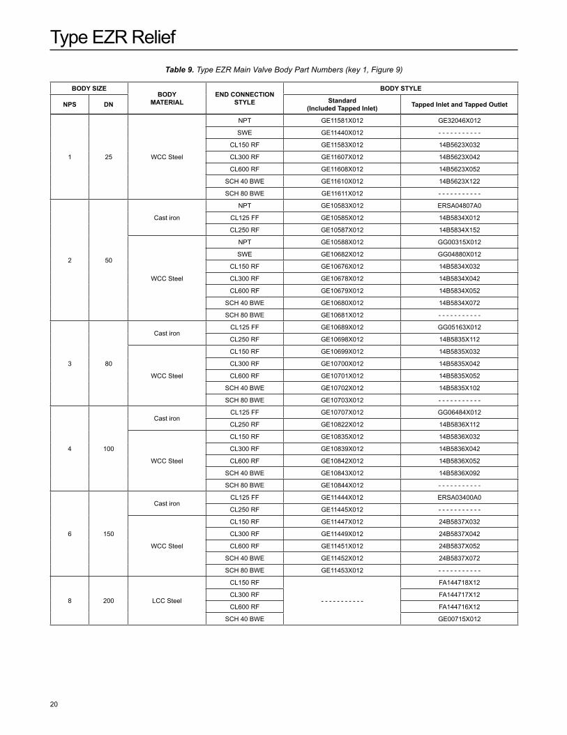
1 Valve Body See Table 9 2 Bonnet Assembly, Steel NPS 1 / DN 25 body 39B2403X022 NPS 2 / DN 50 body 38B2122X022 NPS 3 / DN 80 body 38B5963X022 NPS 4 / DN 100 body 38B2133X022 NPS 6 / DN 150 body 49B0355X022 NPS 8 / DN 200 body GE18697X022 3 Cap Screw, Zinc-plated steel NPS 1 / DN 25 body (4 required) 1R281124052 NPS 2 / DN 50 body (8 required) 1A453324052 NPS 3 / DN 80 body (8 required) 1A454124052 NPS 4 / DN 100 body (8 required) 1A440224052 NPS 6 / DN 150 body (12 required) 1U513124052
Key Description Part number
*Recommended Spare Part
Type EZR Relief
15
*Recommended Spare Part
Key Description Part number Key Description Part number 4 Hex Nut (2 required) NPS 1 and 2 / DN 25 and 50 bodies,
Zinc-plated carbon steel 1H322228982 NPS 3, 4 and 6 / DN 80, 100 and 150 bodies
Stainless steel 1L286338992 NPS 8 / DN 200 body, Zinc-plated carbon steel 1A573528982 5 Top Plug, Stainless Steel NPS 1 / DN 25 body 29B2404X012 NPS 2 / DN 50 body 28B2130X012 NPS 3 / DN 80 body 28B8511X012 NPS 4 / DN 100 body 28B5964X012 NPS 6 / DN 150 body 39B0370X012 NPS 8 / DN 200 body 39B5071X012 6* O-ring NPS 1 / DN 25 body Nitrile (NBR) 18B3438X012 Fluorocarbon (FkM) 1N430306382 NPS 2 / DN 50 body Nitrile (NBR) 18B3438X012 Fluorocarbon (FkM) 1N430306382 NPS 3 / DN 80 body Nitrile (NBR) 10A8931X012 Fluorocarbon (FkM) 10A8931X052 NPS 4 / DN 100 body Nitrile (NBR) 10A8931X012 Fluorocarbon (FkM) 10A8931X052 NPS 6 / DN 150 body Nitrile (NBR) 10A3800X012 Fluorocarbon (FkM) 1R727606382 NPS 8 / DN 200 body Nitrile (NBR) 10A3800X012 Fluorocarbon (FkM) 1R727606382 7 Cage, Stainless steel NPS 1 / DN 25 body 39B2413X012 NPS 2 / DN 50 body 37B9748X012 NPS 3 / DN 80 body 48B5961X012 NPS 4 / DN 100 body 48B2135X012 NPS 6 / DN 150 body 49B0353X012 NPS 8 / DN 200 body 59B5955X012 8* Cage O-ring NPS 1 / DN 25 body Nitrile (NBR) 14A5713X012 Fluorocarbon (FkM) 13A2351X012 NPS 2 / DN 50 body Nitrile (NBR) 10B4428X012 Fluorocarbon (FkM) 10B4428X022 NPS 3 / DN 80 body Nitrile (NBR) 10B4366X012 Fluorocarbon (FkM) 10B4366X022 NPS 4 / DN 100 body Nitrile (NBR) 10B4373X012 Fluorocarbon (FkM) 10B4373X022 NPS 6 / DN 150 body Nitrile (NBR) 1H862306992 Fluorocarbon (FkM) 1H8623X0022 NPS 8 / DN 200 body Nitrile (NBR) 1V9229X0042 Fluorocarbon (FkM) 1V9229X0022 9* Diaphragm NPS 1 / DN 25 body 17E97 Nitrile (NBR), high-pressure GE11960X012 17E68 Nitrile (NBR), low-temperature 30C1009X012 17E88 Fluorocarbon (FkM) 39B2397X022 NPS 2 / DN 50 body 17E68 Nitrile (NBR), low temperature 29B1909X012 17E97 Nitrile (NBR), high-pressure 28B2123X052 17E88 Fluorocarbon (FkM) 29B2715X012 NPS 3 / DN 80 body 17E68 Nitrile (NBR), low temperature 38B9886X012 17E97 Nitrile (NBR), high-pressure 39B2726X012 17E88 Fluorocarbon (FkM) 38B8512X022
9* Diaphragm (continued) NPS 4 / DN 100 body 17E68 Nitrile (NBR), low temperature 38B8509X012 17E97 Nitrile (NBR), high-pressure 39B3996X012 17E88 Fluorocarbon (FkM) 39B1154X012 NPS 6 / DN 100 body 17E97 Nitrile (NBR) 49B0357X012 17E88 Fluorocarbon (FkM) 40C1035X012 NPS 8 / DN 200 body 17E97 Nitrile (NBR) 40C1888X012 10* O-ring NPS 1 / DN 25 body Nitrile (NBR) 1E216306992 Fluorocarbon (FkM) 1L949306382 NPS 2 / DN 50 body Nitrile (NBR) 1E216306992 Fluorocarbon (FkM) 1L949306382 NPS 3 and 4 / DN 80 and 100 bodies Nitrile (NBR) 1J4888X0052 Fluorocarbon (FkM) 1J4888X0032 NPS 6 / DN 100 body Nitrile (NBR) 11A8741X052 Fluorocarbon (FkM) 11A8741X012 NPS 8 / DN 200 body Nitrile (NBR) 1F4636X0032 Fluorocarbon (FkM) 1N571406382 11 Bottom Plug, Stainless steel NPS 1 / DN 25 body 19B2407X012 NPS 2 / DN 50 body 18B2127X012 NPS 3 / DN 80 body 18B8513X012 NPS 4 / DN 100 body 18B5966X012 NPS 6 / DN 150 body 29B0763X012 12 Main Spring NPS 1 / DN 25 body White 19B2399X012 Light Blue 19B2400X012 Black 19B2401X012 NPS 2 / DN 50 body Yellow 19B0951X012 Green 18B2126X012 Red 18B5955X012 Purple GE05504X012 NPS 3 / DN 80 body Yellow T14184T0012 Light Blue 19B0781X012 Black 19B0782X012 NPS 4 / DN 100 body Yellow T14184T0012 Green 18B8501X012 Red 18B8502X012 NPS 6 / DN 150 body Yellow 19B0364X012 Green 19B0366X012 Red 19B0365X012 NPS 8 / DN 200 body Yellow GE09393X012 Green GE09396X012 Red GE09397X012 13 Flanged Locknut, Steel NPS 2 / DN 50 body 18B2139X012 NPS 3 and 4 / DN 80 and 100 bodies 15A7591X012 NPS 6 / DN 150 body 19B0361X012 NPS 8 / DN 200 body 10C1267X012 14* Top Plug O-ring NPS 1 / DN 25 body Nitrile (NBR) 13A1584X052 Fluorocarbon (FkM) 13A1584X022 NPS 2 / DN 50 body Nitrile (NBR) 13A1584X052 Fluorocarbon (FkM) 13A1584X022
Type EZR Relief
16
Key Description Part number Key Description Part number14* Top Plug O-ring (continued) NPS 3 and 4 / DN 80 and 100 bodies Nitrile (NBR) 10A3803X062 Fluorocarbon (FkM) 10A3803X032 NPS 6 / DN 150 body Nitrile (NBR) T12050X0012 Fluorocarbon (FkM) T12050X0022 NPS 8 / DN 200 body Nitrile (NBR) T12050X0012 Fluorocarbon (FkM) T12050X0022 15 Stem, Stainless steel NPS 1 and 2 / DN 25 and 50 bodies T14185T0012 NPS 3 and 4 / DN 80 and 100 bodies T21074T0012 NPS 6 / DN 150 body 29B0366X012 NPS 8 / DN 200 body 29B5076X012 16 Backup Ring, Polytetrafluoroethylene (PTFE) (2 required) NPS 1 and 2 / DN 25 and 50 bodies 1N659106242 NPS 3, 4 and 6 / DN 80, 100 and 150 bodies 1J418806992 NPS 8 / DN 200 body 1k786806992 17 Upper Spring Seat, Stainless steel NPS 1 and 2 / DN 25 and 50 bodies 18B2129X012 NPS 3 and 4 / DN 80 and 100 bodies 18B5968X012 NPS 6 / DN 150 body 29B0764X012 NPS 8 / DN 200 body 20C1357X012 18* O-ring NPS 1 and 2 / DN 25 and 50 bodies Nitrile (NBR) 1H2926X0032 Fluorocarbon (FkM) 1H2926X0022 NPS 3, 4 and 6 / DN 80, 100 and 150 bodies Nitrile (NBR) 1D191706992 Fluorocarbon (FkM) 1N423906382 NPS 8 / DN 200 body Nitrile (NBR) 1E472706992 Fluorocarbon (FkM) 1N430406382 19 Indicator Fitting, Stainless steel NPS 1 and 2 / DN 25 and 50 bodies 28B2128X012 NPS 3 and 4 / DN 80 and 100 bodies 28B5969X012 NPS 6 / DN 150 body 39B0358X012 NPS 8 / DN 200 body 30C1356X012 19 Indicator Plug, Stainless steel NPS 1 / DN 25 body 19B2409X012 NPS 2 / DN 50 body GE17585X012 NPS 3 and 4 / DN 80 and 100 bodies 28B5970X012 NPS 6 and 8 / DN 150 and 200 bodies 39B0767X012 20 Indicator Washer NPS 1 and 2 / DN 25 and 50 bodies 18B2138X012 NPS 3, 4 and 6 / DN 80, 100 and 150 bodies 18B8503X012 NPS 8 / DN 200 body 20C2461X012 21 Indicator Cover, Plastic NPS 1 and 2 / DN 25 and 50 bodies T14188T0012 NPS 3 and 4 / DN 80 and 100 bodies 19B2270X012 NPS 6 and 8 / DN 150 and 200 bodies 19B4691X012 22 Indicator Protector, Plastic NPS 1 and 2 / DN 25 and 50 bodies 24B1301X012 NPS 3, 4, 6 and 8 / DN 80, 100, 150 and 200 bodies 29B2269X012 23 Inlet Strainer, Stainless steel NPS 1 / DN 25 body 20B8004X012 NPS 2 / DN 50 body 10B4409X012 NPS 3 / DN 80 body 20B4367X012 NPS 4 / DN 100 body 20B4374X012 NPS 6 / DN 150 body 20B7853X012 NPS 8 / DN 200 body 29B5966X012 23 Strainer Replacement Shim, Stainless steel NPS 1 / DN 25 body 13B8061X012 NPS 2 / DN 50 body 13B8062X012 NPS 3 / DN 80 body 13B8063X012 NPS 4 / DN 100 body 13B8064X012 NPS 6 / DN 150 body 13B8065X012 NPS 8 / DN 200 body 39B5967X012
24 Nameplate - - - - - - - - - - - 25 Flow Arrow, Stainless steel - - - - - - - - - - - 26 Drive Screw, Stainless steel (5 required) 1A368228982 NPS 8 / DN 200 body (6 required) 28* O-ring NPS 1 / DN 25 body Nitrile (NBR) 19B2838X012 Fluorocarbon (FkM) 19B2838X022 NPS 2 / DN 50 body Nitrile (NBR) 18B2124X012 Fluorocarbon (FkM) 18B2124X022 NPS 3 / DN 80 body Nitrile (NBR) 18B8514X012 Fluorocarbon (FkM) 18B8514X022 NPS 4 / DN 100 body Nitrile (NBR) 18B2140X012 Fluorocarbon (FkM) 18B2140X022 NPS 6 / DN 150 body Nitrile (NBR) 19B0359X012 Fluorocarbon (FkM) 10A3591X012 NPS 8 / DN 200 body Nitrile (NBR) 1P5585X0022 Fluorocarbon (FkM) 1P5585X0032 47 Nut, steel (NPS 8 / DN 200 only, 8 required) 1A4452X0612 63 Pilot Supply Pipe Plug (2 required) NPS 1 to 6 / DN 25 to 150 1A767524662 NPS 8 / DN 200 LCC Steel body 1A369224492 WCC Steel body 1A767524662 64 Bonnet Pipe Plug, Carbon steel 1A767524662 NPS 1 to 6 / DN 25 to 150 1A767524662 NPS 8 / DN 200 1A369224492 70* O-ring NPS 1 and 2 / DN 25 and 50 body Nitrile (NBR) 13A1584X052 Fluorocarbon (FkM) 13A1584X022 NPS 3 and 4 / DN 80 and 100 bodies Nitrile (NBR) 10A3803X062 Fluorocarbon (FkM) 10A3803X032 NPS 6 and 8 / DN 150 and 200 body Nitrile (NBR) T12050X0012 Fluorocarbon (FkM) T12050X0022 71 Restrictor Plate, Stainless steel NPS 1 / DN 25 body For 60% Capacity Trim 19B2835X012 For 30% Capacity Trim 19B2836X012 NPS 2 / DN 50 body For 60% Capacity Trim 18B2144X012 For 30% Capacity Trim 18B2145X012 NPS 3 / DN 80 body For 60% Capacity Trim 28B8516X012 For 30% Capacity Trim 28B8517X012 NPS 4 / DN 100 body For 60% Capacity Trim 28B8504X012 For 30% Capacity Trim 28B8505X012 NPS 6 / DN 150 body For 100% Capacity Trim 49B0367X012 For 60% Capacity Trim 49B0368X012 For 30% Capacity Trim 49B0369X012 72 E-ring, for Restricted Trim, Carbon steel NPS 1 / DN 25 body 19B2411X012 NPS 2 / DN 50 body 16A7882X012 NPS 3 / DN 80 body 18B8518X012 NPS 4 / DN 100 body 18B8506X012 79 Washer, Stainless steel (NPS 6 / DN 150 body only) 19B0362X012 83 Machine Screw, Stainless steel
(NPS 2 / DN 50 only) 18B5956X012 121* O-ring NPS 6 / DN 150 body only Nitrile (NBR) 1D269206992 Fluorocarbon (FkM) 1D2692X0022
*Recommended Spare Part
Type EZR Relief
17
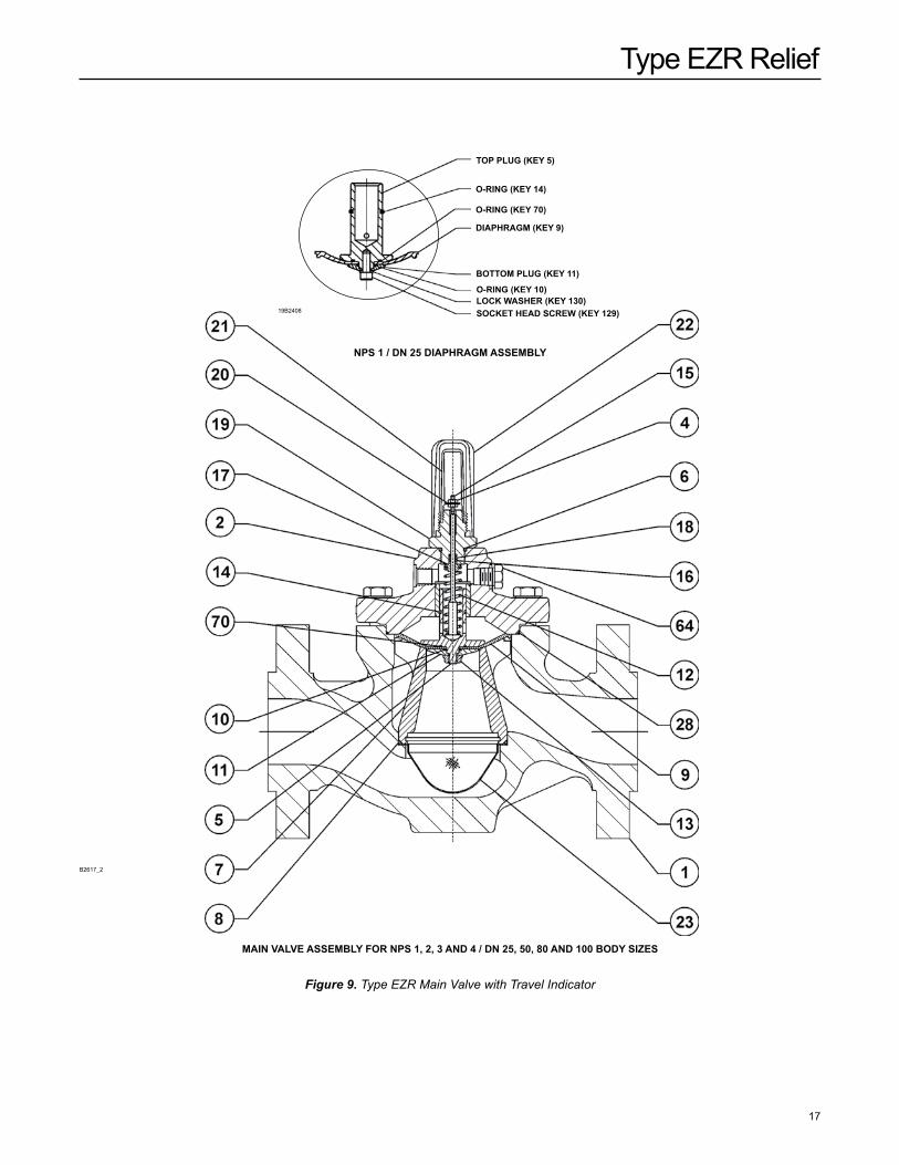
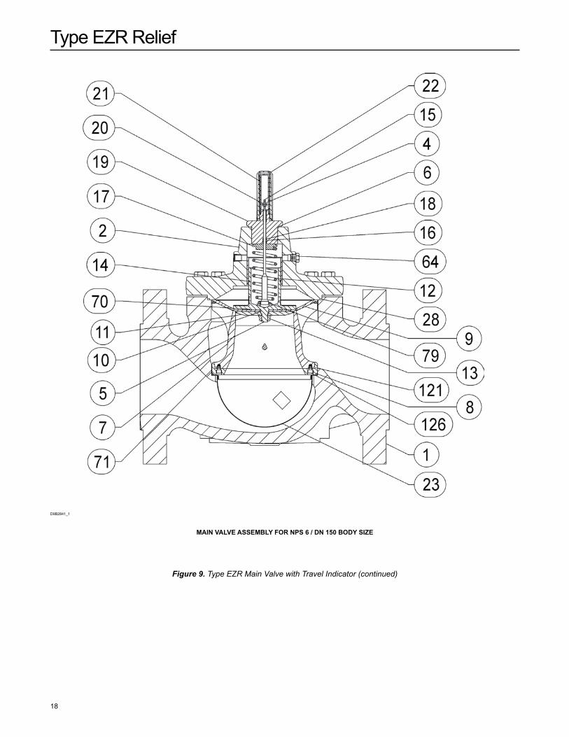
Figure 9. Type EZR Main Valve with Travel Indicator
19B2408
TOP PLUg (KEY 5)
O-RIng (KEY 14)
O-RIng (KEY 70)
DIaPHRagM (KEY 9)
BOTTOM PLUg (KEY 11)
O-RIng (KEY 10)LOCK WaSHER (KEY 130)SOCKET HEaD SCREW (KEY 129)
nPS 1 / Dn 25 DIaPHRagM aSSEMBLY
MaIn VaLVE aSSEMBLY FOR nPS 1, 2, 3 anD 4 / Dn 25, 50, 80 anD 100 BODY SIZES
B2617_2
Type EZR Relief
18
Figure 9. Type EZR Main Valve with Travel Indicator (continued)
MaIn VaLVE aSSEMBLY FOR nPS 6 / Dn 150 BODY SIZE
D9B2841_1
Type EZR Relief
19
24 3
26 25
48B2142_C
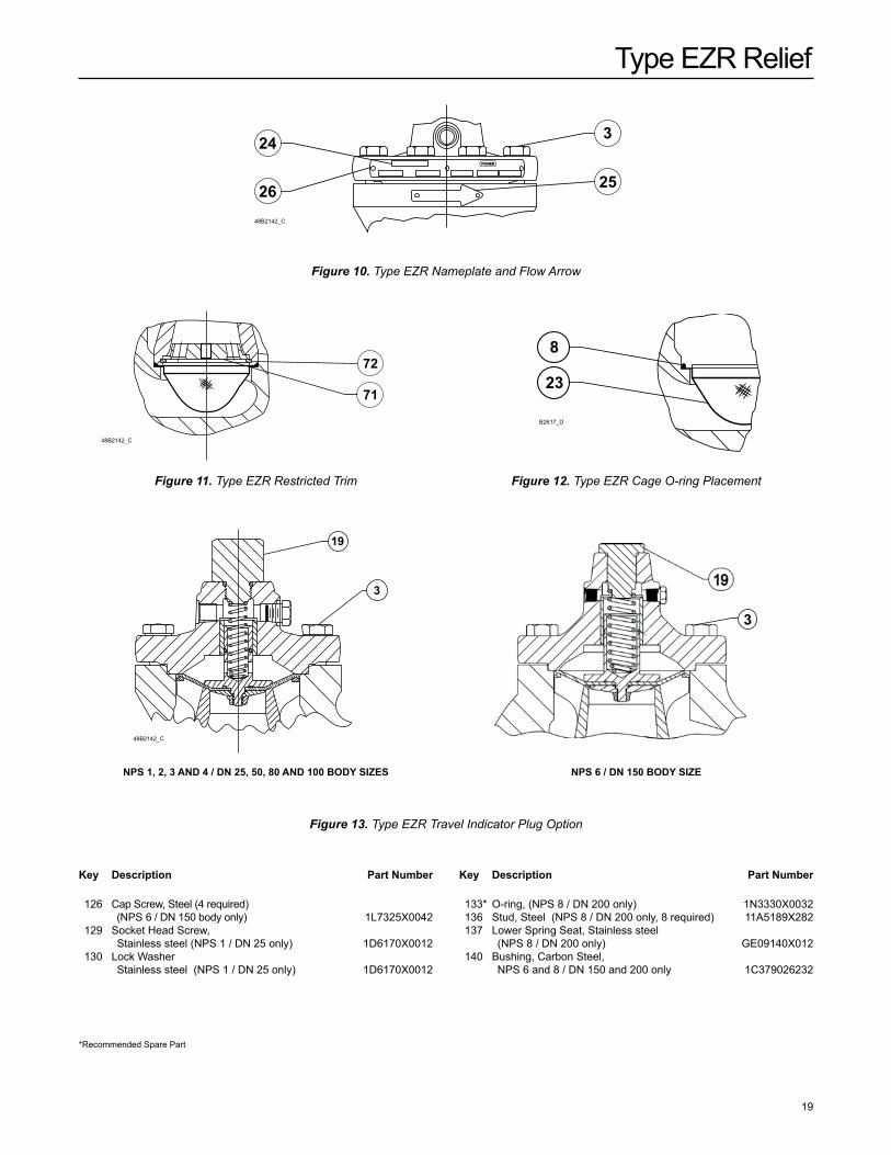
Figure 10. Type EZR Nameplate and Flow Arrow
72
71
8
23
48B2142_C
B2617_D
Figure 11. Type EZR Restricted Trim Figure 12. Type EZR Cage O-ring Placement
19
3
48B2142_C
3
nPS 1, 2, 3 anD 4 / Dn 25, 50, 80 anD 100 BODY SIZES nPS 6 / Dn 150 BODY SIZE
Figure 13. Type EZR Travel Indicator Plug Option
126 Cap Screw, Steel (4 required) (NPS 6 / DN 150 body only) 1L7325X0042
129 Socket Head Screw, Stainless steel (NPS 1 / DN 25 only) 1D6170X0012 130 Lock Washer Stainless steel (NPS 1 / DN 25 only) 1D6170X0012
133* O-ring, (NPS 8 / DN 200 only) 1N3330X0032 136 Stud, Steel (NPS 8 / DN 200 only, 8 required) 11A5189X282 137 Lower Spring Seat, Stainless steel
(NPS 8 / DN 200 only) GE09140X012 140 Bushing, Carbon Steel,
NPS 6 and 8 / DN 150 and 200 only 1C379026232
Key Description Part number Key Description Part number
*Recommended Spare Part
Type EZR Relief
20
BODY SIZEBODY
MaTERIaLEnD COnnECTIOn
STYLE
BODY STYLE
nPS Dn Standard(Included Tapped Inlet) Tapped Inlet and Tapped Outlet
1 25 WCC Steel
NPT GE11581X012 GE32046X012
SWE GE11440X012 - - - - - - - - - - -
CL150 RF GE11583X012 14B5623X032
CL300 RF GE11607X012 14B5623X042
CL600 RF GE11608X012 14B5623X052
SCH 40 BWE GE11610X012 14B5623X122
SCH 80 BWE GE11611X012 - - - - - - - - - - -
2 50
Cast iron
NPT GE10583X012 ERSA04807A0
CL125 FF GE10585X012 14B5834X012
CL250 RF GE10587X012 14B5834X152
WCC Steel
NPT GE10588X012 GG00315X012
SWE GE10682X012 GG04880X012
CL150 RF GE10676X012 14B5834X032
CL300 RF GE10678X012 14B5834X042
CL600 RF GE10679X012 14B5834X052
SCH 40 BWE GE10680X012 14B5834X072
SCH 80 BWE GE10681X012 - - - - - - - - - - -
3 80
Cast ironCL125 FF GE10689X012 GG05163X012
CL250 RF GE10698X012 14B5835X112
WCC Steel
CL150 RF GE10699X012 14B5835X032
CL300 RF GE10700X012 14B5835X042
CL600 RF GE10701X012 14B5835X052
SCH 40 BWE GE10702X012 14B5835X102
SCH 80 BWE GE10703X012 - - - - - - - - - - -
4 100
Cast ironCL125 FF GE10707X012 GG06484X012
CL250 RF GE10822X012 14B5836X112
WCC Steel
CL150 RF GE10835X012 14B5836X032
CL300 RF GE10839X012 14B5836X042
CL600 RF GE10842X012 14B5836X052
SCH 40 BWE GE10843X012 14B5836X092
SCH 80 BWE GE10844X012 - - - - - - - - - - -
6 150
Cast ironCL125 FF GE11444X012 ERSA03400A0
CL250 RF GE11445X012 - - - - - - - - - - -
WCC Steel
CL150 RF GE11447X012 24B5837X032
CL300 RF GE11449X012 24B5837X042
CL600 RF GE11451X012 24B5837X052
SCH 40 BWE GE11452X012 24B5837X072
SCH 80 BWE GE11453X012 - - - - - - - - - - -
8 200 LCC Steel
CL150 RF
- - - - - - - - - - -
FA144718X12
CL300 RF FA144717X12
CL600 RF FA144716X12
SCH 40 BWE GE00715X012
Table 9. Type EZR Main Valve Body Part Numbers (key 1, Figure 9)
Type EZR Relief
21
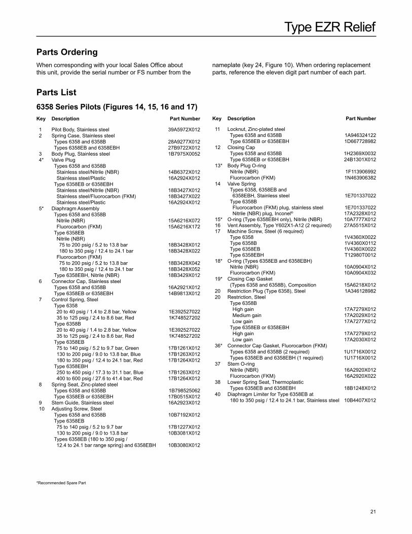
nameplate (key 24, Figure 10). When ordering replacement parts, reference the eleven digit part number of each part.
*Recommended Spare Part
Key Description Part number
Parts OrderingWhen corresponding with your local Sales Office about this unit, provide the serial number or FS number from the
Parts List6358 Series Pilots (Figures 14, 15, 16 and 17)Key Description Part number
1 Pilot Body, Stainless steel 39A5972X012 2 Spring Case, Stainless steel Types 6358 and 6358B 28A9277X012 Types 6358EB and 6358EBH 27B9722X012 3 Body Plug, Stainless steel 1B7975X0052 4* Valve Plug Types 6358 and 6358B Stainless steel/Nitrile (NBR) 14B6372X012 Stainless steel/Plastic 16A2924X012 Type 6358EB or 6358EBH Stainless steel/Nitrile (NBR) 18B3427X012 Stainless steel/Fluorocarbon (FkM) 18B3427X022 Stainless steel/Plastic 16A2924X012 5* Diaphragm Assembly Types 6358 and 6358B Nitrile (NBR) 15A6216X072 Fluorocarbon (FkM) 15A6216X172 Type 6358EB Nitrile (NBR) 75 to 200 psig / 5.2 to 13.8 bar 18B3428X012 180 to 350 psig / 12.4 to 24.1 bar 18B3428X022 Fluorocarbon (FkM) 75 to 200 psig / 5.2 to 13.8 bar 18B3428X042 180 to 350 psig / 12.4 to 24.1 bar 18B3428X052 Type 6358EBH, Nitrile (NBR) 18B3429X012 6 Connector Cap, Stainless steel Types 6358 and 6358B 16A2921X012 Type 6358EB or 6358EBH 14B9813X012 7 Control Spring, Steel Type 6358 20 to 40 psig / 1.4 to 2.8 bar, Yellow 1E392527022 35 to 125 psig / 2.4 to 8.6 bar, Red 1k748527202 Type 6358B 20 to 40 psig / 1.4 to 2.8 bar, Yellow 1E392527022 35 to 125 psig / 2.4 to 8.6 bar, Red 1k748527202 Type 6358EB 75 to 140 psig / 5.2 to 9.7 bar, Green 17B1261X012 130 to 200 psig / 9.0 to 13.8 bar, Blue 17B1263X012 180 to 350 psig / 12.4 to 24.1 bar, Red 17B1264X012 Type 6358EBH 250 to 450 psig / 17.3 to 31.1 bar, Blue 17B1263X012 400 to 600 psig / 27.6 to 41.4 bar, Red 17B1264X012 8 Spring Seat, Zinc-plated steel Types 6358 and 6358B 1B798525062 Type 6358EB or 6358EBH 17B0515X012 9 Stem Guide, Stainless steel 16A2923X012 10 Adjusting Screw, Steel Types 6358 and 6358B 10B7192X012 Type 6358EB 75 to 140 psig / 5.2 to 9.7 bar 17B1227X012 130 to 200 psig / 9.0 to 13.8 bar 10B3081X012 Types 6358EB (180 to 350 psig /
12.4 to 24.1 bar range spring) and 6358EBH 10B3080X012
11 Locknut, Zinc-plated steel Types 6358 and 6358B 1A946324122 Type 6358EB or 6358EBH 1D667728982 12 Closing Cap Types 6358 and 6358B 1H2369X0032 Type 6358EB or 6358EBH 24B1301X012 13* Body Plug O-ring Nitrile (NBR) 1F113906992 Fluorocarbon (FkM) 1N463906382 14 Valve Spring
Types 6358, 6358EB and 6358EBH, Stainless steel 1E701337022 Type 6358B Fluorocarbon (FkM) plug, stainless steel 1E701337022 Nitrile (NBR) plug, Inconel® 17A2328X012
15* O-ring (Type 6358EBH only), Nitrile (NBR) 10A7777X012 16 Vent Assembly, Type Y602X1-A12 (2 required) 27A5515X012 17 Machine Screw, Steel (6 required) Type 6358 1V4360X0022 Type 6358B 1V4360X0112 Type 6358EB 1V4360X0022 Type 6358EBH T12980T0012 18* O-ring (Types 6358EB and 6358EBH) Nitrile (NBR) 10A0904X012 Fluorocarbon (FkM) 10A0904X032 19* Closing Cap Gasket
(Types 6358 and 6358B), Composition 15A6218X012 20 Restriction Plug (Type 6358), Steel 1A346128982 20 Restriction, Steel Type 6358B High gain 17A7279X012 Medium gain 17A2029X012 Low gain 17A7277X012 Type 6358EB or 6358EBH High gain 17A7279X012 Low gain 17A2030X012 36* Connector Cap Gasket, Fluorocarbon (FkM) Types 6358 and 6358B (2 required) 1U1716X0012 Types 6358EB and 6358EBH (1 required) 1U1716X0012 37 Stem O-ring Nitrile (NBR) 16A2920X012 Fluorocarbon (FkM) 16A2920X022 38 Lower Spring Seat, Thermoplastic Types 6358EB and 6358EBH 18B1248X012 40 Diaphragm Limiter for Type 6358EB at 180 to 350 psig / 12.4 to 24.1 bar, Stainless steel 10B4407X012
Type EZR Relief
22
A6920
6358 SERIES PILOT InTERIOR VIEW
B2619-2
TYPE 6358B PILOT InTERIOR VIEW
Figure 14. Types 6358 and 6358B Pilots
Type EZR Relief
23
B2620-2 B2621-2
TYPE 6358EB PILOT InTERIOR VIEW TYPE 6358EBH PILOT InTERIOR VIEW
A6920-2
DETaIL OF TYPE 6358EB PILOT DIaPHRagM LIMITER FOR 180 to 350 psig / 12.4 to 24.1 bar
SET PRESSURE RangE InTERIOR VIEW
Figure 15. Types 6358EB and 6358EBH Pilots
Type EZR Relief
24
17
B2620-1
TYPE 6358EB PILOT EXTERIOR VIEW
Figure 16. 6358 Series Pilots Exterior View
TYPE 6358EBH PILOT EXTERIOR VIEW
B2621-1
17
TYPES 6358 anD 6358B PILOTS EXTERIOR VIEW
B2619-1
Figure 17. 6358 Series Pilot Mounting Parts
29
B2044-3
VEnT aSSEMBLY
30B4383
STanDaRD PILOT MOUnTIng
UPSTREaM COnTROL LInE COnnECTIOn
PILOT EXHaUST COnnECTIOn
17
Type EZR Relief
25
6358 Series Pilot Mounting Parts (Figure 17)Standard Pilot MountingKey Description Part number
29 Mounting Pipe Nipple NPS 1 / DN 25 1N584226232 NPS 2 / DN 50 1N624026232 NPS 3 / DN 80 1U264426232 NPS 4 / DN 100 1U5728X0012 NPS 6 / DN 150 1C210026232 NPS 8 / DN 200 1C215726012 44 Vent, Type Y602-12 - - - - - - - - - - -
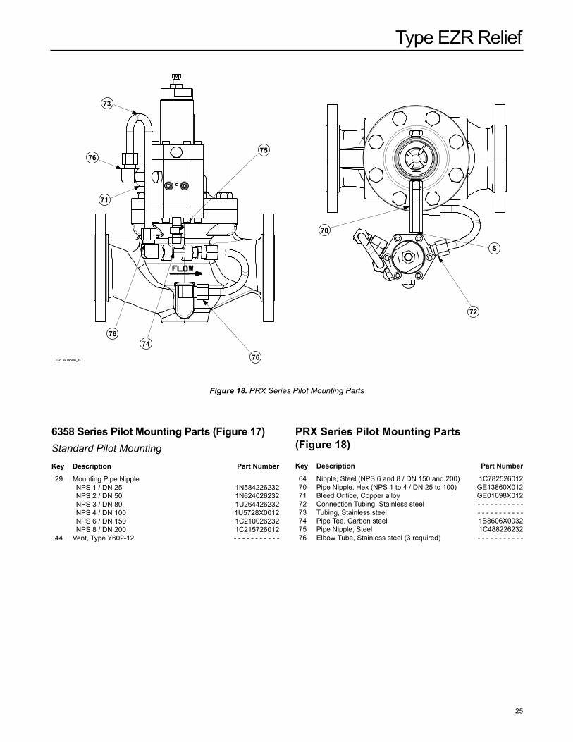
Figure 18. PRX Series Pilot Mounting Parts
75
73
76
71
7674
76
S
72
70
ERCA04506_B
PRX Series Pilot Mounting Parts (Figure 18)
Key Description Part number
64 Nipple, Steel (NPS 6 and 8 / DN 150 and 200) 1C782526012 70 Pipe Nipple, Hex (NPS 1 to 4 / DN 25 to 100) GE13860X012 71 Bleed Orifice, Copper alloy GE01698X012 72 Connection Tubing, Stainless steel - - - - - - - - - - - 73 Tubing, Stainless steel - - - - - - - - - - - 74 Pipe Tee, Carbon steel 1B8606X0032 75 Pipe Nipple, Steel 1C488226232 76 Elbow Tube, Stainless steel (3 required) - - - - - - - - - - -
Type EZR Relief
26
Figure 19. Type PRX/182 Pilot Schematics
A
A
L
B
S
28 31 29
28
34
34
22
19
14
17
16
18
1413
1
2
3
4
5
6
7
8
9
10
11
12
B
13
15112010
11
21
25
23
24
18
11
26
35
4
4
A
A
L
B
S
28 31 29
28
34
34
22
19
14
17
16
18
1413
1
2
3
4
5
6
7
8
9
10
11
12
B
13
15112010
11
21
25
23
24
18
11
26
35
4
4
A
A
L
B
S
28 31 29
28
34
34
22
19
14
17
16
18
1413
1
2
3
4
5
6
7
8
9
10
11
12
B
13
15112010
11
21
25
23
24
18
11
26
35
4
4
Type EZR Relief
27
PRX Series Pilots (Figure 19)Key Description Part number
Parts kits Elastomer Parts kits (includes keys: 4, 5, 14, 17, 18, 22, 25 and 28) Types PRX/182 and PRX/182-AP Nitrile (NBR) RPRX00X0N12 Fluorocarbon (FkM) RPRX00X0F12
1 Adjusting Screw, Stainless steel M0253340X12 2 Locknut M5036008X12 3 Cap, Steel M0253350X12 4* Spring Case O-ring, (2 required for Type PRX-AP) Nitrile (NBR) M6010178X12 Fluorocarbon (FkM) M6020112X12 5* O-ring Nitrile (NBR) M6010005X12 Fluorocarbon (FkM) M6020001X12 6 Upper Spring Seat, Stainless steel M0253360X12 7 Spring See Table 3 8 Spring Case, Steel M0298540X12 9 Lower Spring Seat, Stainless steel M0253380X12 10 Machine Screw, Zinc-plated steel (12 required) M5011018X12 11 Washer (14 required) M5055001X12 12 Filter M4500367X12 13 Diaphragm Plate, Stainless steel (2 required) M0253390X12 14* Diaphragm
Nitrile (NBR) GG05785X012 Fluorocarbon (FkM) GG05785X022
15 Diaphragm Plate, Stainless steel M0253410X12 16 Body, Carbon steel M0253310X12 17* Orifice O-ring Nitrile (NBR) M6010003X12 Fluorocarbon (FkM) M6020126X12 18* Lower Cover O-ring (2 required) Nitrile (NBR) M6010098X12 Fluorocarbon (FkM) M6020132X12 19 Seat, Stainless steel M0253440X12 20 Nut, Zinc-plated steel M5002004X12 21 Lower Cover, Steel M0298600X12 22* Disk Holder Polyurethane (PU) ERAA11220A0 Fluorocarbon (FkM) M0279950X12 23 Stem, Steel M0253430X12 24 Nameplate - - - - - - - - - - - 25* Stem O-ring Nitrile (NBR) M6010223X12 Fluorocarbon (FkM) M6020133X12 26 Upper Diaphragm Nut M5028005X12 28* Restrictor/Damper O-ring,
Fluorocarbon (FkM) (2 required) M6020054X12 29 Nameplate - - - - - - - - - - - 31 Nameplate Screw, Stainless steel M5061001X12 33 Restrictor Plug M0257920X12 34 Pipe Plug, Stainless steel M4500328X12 35 Spring Barrel Extension for AP, Steel M0274100X12
*Recommended Spare Part
Key Description Part number
Type EZR Relief
©Emerson Process Management Regulator Technologies, Inc., 1999, 2015; All Rights Reserved
The Emerson logo is a trademark and service mark of Emerson Electric Co. All other marks are the property of their prospective owners. Fisher is a mark owned by Fisher Controls International LLC, a business of Emerson Process Management.
The contents of this publication are presented for informational purposes only, and while every effort has been made to ensure their accuracy, they are not to be construed as warranties or guarantees, express or implied, regarding the products or services described herein or their use or applicability. We reserve the right to modify or improve the designs or specifications of such products at any time without notice.
Emerson Process Management Regulator Technologies, Inc. does not assume responsibility for the selection, use or maintenance of any product. Responsibility for proper selection, use and maintenance of any Emerson Process Management Regulator Technologies, Inc. product remains solely with the purchaser.
Industrial Regulators
Emerson Process Management Regulator Technologies, Inc.
USA - HeadquartersMcKinney, Texas 75070 USATel: +1 800 558 5853Outside U.S. +1 972 548 3574
Asia-PacificShanghai 201206, ChinaTel: +86 21 2892 9000
EuropeBologna 40013, ItalyTel: +39 051 419 0611
Middle East and AfricaDubai, United Arab EmiratesTel: +971 4811 8100
Natural Gas Technologies
Emerson Process ManagementRegulator Technologies, Inc.
USA - HeadquartersMcKinney, Texas 75070 USATel: +1 800 558 5853Outside U.S. +1 972 548 3574
Asia-PacificSingapore 128461, SingaporeTel: +65 6770 8337
EuropeBologna 40013, ItalyTel: +39 051 419 0611Chartres 28008, FranceTel: +33 2 37 33 47 00
Middle East and AfricaDubai, United Arab EmiratesTel: +971 4811 8100
TESCOM
Emerson Process ManagementTescom Corporation
USA - HeadquartersElk River, Minnesota 55330-2445, USATels: +1 763 241 3238 +1 800 447 1250
EuropeSelmsdorf 23923, GermanyTel: +49 38823 31 287
Asia-PacificShanghai 201206, ChinaTel: +86 21 2892 9499
For further information visit www.emersonprocess.com/regulators