Embed Size (px)
Citation preview
Thank you for choosing a Shakespeare product. Shakespeareworks hard to build reliability and durability into all of its productsfor maximum customer satisfaction. Customer comments arewelcome. Before installing, please study the diagram and checkparts supplied against those listed.
Supplied parts:
(1) SRA-50 Antenna with 6” cable and TNC Female connector
(1) 25’ Coax Cable with TNC Male and SMB connectors
The length of the cable run from the antenna to the satellite radio receiver can be extended byusing the one of the cable kits listed on page 6 (each sold separately). Note: These cablesreplace the 25’ cable supplied with the antenna, and must be used as supplied. They cannotbe lengthened, shortened, or connected together as extensions.
(1) Bag containing: (1) Extension shaft, (1) Lockwasher, (1) Retaining nut
(1) Antenna Base for low profile mounting
(1) Base Gasket
(1) Pedestal Top for mounting on standard 1”-14 mounts
(1) Rubber Seal Ring
(1) Pedestal Bottom for pedestal mounting
Tools required: Screwdriver, Marking pencil, drill and drill bits (9/16”, 7/64”), needle nose pliers,or other tools appropriate to your specific application may also be needed.
Required materials: Silicone Sealer (RTV) when flush mounting
DO NOT CUT OR ALTER THE ANTENNA CABLE.DO NOT REMOVE ITS CONNECTOR.
IMPORTANT: Please read all instructions before installing.
Optional Accessories
SRS-3-Kit DC Voltage Splitter for antenna cables up to 50’
The length of the cable run from the antenna to the satellite radio receiver can be extended by using theone of the optional cable kits listed above. Note: These cables replace the 25’ cable supplied with theantenna, and must be used as supplied. They cannot be lengthened, shortened, or connected together asextensions.
Electronic Products Group3801 Westmore Dr., Columbia, SC 29223 · 803-227-1590 · Fax: 803-419-3099
www.shakespeare-marine.com
©2015 Shakespeare Company LLC, a subsidiary of Jarden Corporation (NYSE: JAH). All rights reserved
1
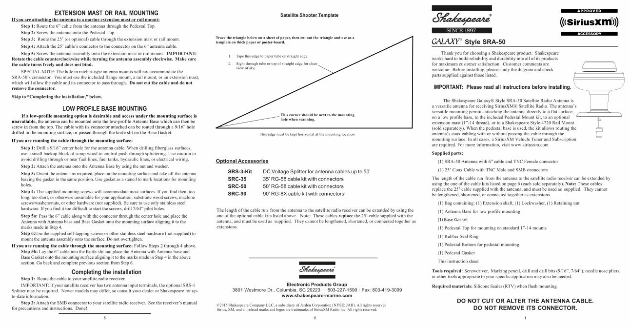
Satellite Shooter Template
Trace the triangle below on a sheet of paper, then cut out the triangle and use as atemplate on thick paper or poster-board.
1. Tape this edge to paper tube or straight edge.
2. Sight through tube or top of straight edge for clearview of sky.
This corner should be next to the mountinghole when scanning.
This edge must be kept horizontal at the mounting location
EXTENSION MAST OR RAIL MOUNTINGIf you are attaching the antenna to a marine extension mast or rail mount:
Step 1: Route the 6” cable from the antenna through the Pedestal Top.Step 2: Screw the antenna onto the Pedestal Top.Step 3: Route the 25’ (or optional) cable through the extension mast or rail mount.Step 4: Attach the 25’ cable’s connector to the connector on the 6” antenna cable.
Step 1:
Step 5: Screw the antenna assembly onto the extension mast or rail mount. IMPORTANT:Rotate the cable counterclockwise while turning the antenna assembly clockwise. Make surethe cable turns freely and does not bind.
SPECIAL NOTE: The hole in ratchet-type antenna mounts will not accommodate theSRA-50’s connector. You must use the included flange mount, a rail mount, or an extension mast,which will allow the cable and its connector to pass through. Do not cut the cable and do notremove the connector.
Skip to “Completing the installation,” below.
Sirius, XM, and all related marks and logos are trademarks of SiriusXM Radio Inc. All rights reserved.
The Shakespeare Galaxy® Style SRA-50 Satellite Radio Antenna is a versatile antenna for receiving SiriusXM® Satellite Radio. The antenna’s versatile mounting permits attaching the antenna directly to a flat surface, on a low profile base, to the included Pedestal Mount kit, to an optional extension mast (1”-14 thread), or to a Shakespeare Style 4720 Rail Mount (sold separately). When the pedestal base is used, the kit allows routing the antenna’s coax cabling with or without passing the cable through the mounting surface. In all cases, a SiriusXM Vehicle Tuner and Subscription are required. For more information, visit www.siriusxm.com
(1) Pedestal Gasket
This instruction sheet
Style SRA-50
5 6
If a low-profile mounting option is desirable and access under the mounting surface is unavailable, the antenna can be mounted onto the low-profile Antenna Base which can then be screw in from the top. The cable with its connector attached can be routed through a 9/16” hole drilled in the mounting surface, or passed through the knife slit on the Base Gasket.
If you are running the cable through the mounting surface:
If you are running the cable through the mounting surface: Follow Steps 2 through 4 above.
LOW PROFILE BASE MOUNTING
Step 2: Attach the antenna onto the Antenna Base by using the nut and washer.Step 3:
Step 4:
Drill a 9/16” center hole for the antenna cable. When drilling fiberglass surfaces, use a small backup block of scrap wood to control push-through splintering. Use caution to avoid drilling through or near fuel lines, fuel tanks, hydraulic lines, or electrical wiring.
Orient the antenna as required, place on the mounting surface and take off the antenna leaving the gasket in the same position. Use gasket as a stencil to mark locations for mounting holes.
Step 6:Use the supplied self-tapping screws or other stainless steel hardware (not supplied) to mount the antenna assembly onto the surface. Do not overtighten.
Step 5a: Pass the 6” cable along with the connector through the center hole and place the Antenna with Antenna base and Base Gasket onto the mounting surface aligning it to the marks made in Step 4.
Step 5b: Lay the 6” cable into the Knife-slit and place the Antenna with Antenna base and Base Gasket onto the mounting surface aligning it to the marks made in Step 4 in the above section. Go back and complete previous section from Step 6.
The supplied mounting screws will accommodate most surfaces. If you find them too long, too short, or otherwise unsuitable for your application, substitute wood screws, machine screws/washers/nuts, or other hardware (not supplied). Be sure to use only stainless steel hardware. If you find it too difficult to start the screws, drill 7/64” pilot holes.
Completing the installationStep 1: Route the cable to your satellite radio receiver.IMPORTANT: If your satellite receiver has two antenna input terminals, the optional SRS-1
Splitter may be required. Newer models may differ, so consult your dealer or Shakespeare for up-to-date information.
Step 2: Attach the SMB connector to your satellite radio receiver. See the receiver’s manualfor precautions and instructions. Done!
SRC-35 35’ RG-58 cable kit with connectorsSRC-50 50’ RG-58 cable kit with connectorsSRC-90 90’ RG-8X cable kit with connectors
IMPORTANT: Rotate the cable counterclockwise while turning the Thread Adapter clockwise. Make sure the cable turns freely and does not bind.
Choose a mounting location. The SRA-50 antenna must be mounted horizontally in a locationthat is open and has a clear view of the sky. It must be mounted away from any metal objects orother structures that could block the line-of-sight reception of the satellite signal. The height of theantenna is not as important as having a clear view of the horizon. To determine the best location forthe SRA-50, hold the Satellite Shooter template (back page) horizontally at the chosen mountinglocation and follow the instructions on the template. Scan a full circle with the Shooter to makesure no obstacles block the antenna’s view of the sky from overhead.
The Pedestal mounting requires a flat, not curved surface, or the antenna can be mounted onthe 1”-14 thread end of a marine antenna extension mast or a Shakespeare Style 4720 Rail Mount(each sold separately). The antenna’s cable can be routed through a hole in the mounting surface,through the Pedestal, or through the extension mast.
IMPORTANT:
In choosing how and where to mount the antenna, consider the accessibility of the areaunderneath, and whether the area is clear of any wires or other obstructions. Choose a convenientpathway for running the coax cable as far as possible from other electrical cables.
If the distance between the antenna and your Satellite receiver is more than 25 feet, specialShakespeare cable kits are available (see Optional Accessories, back page). Acquire the appropriatekit before proceeding.
SURFACE MOUNTINGIf you are attaching the antenna directly to a flat surface, the cable with its connector attachedcan be routed through a 9/16” hole drilled in the mounting surface.
Do not cut the cable and do not remove the connector.
Step 1: Drill a 9/16" mounting hole. For mounting surfaces from 1/4" to 1" thick, use theextension shaft (supplied).
· Route the 6" antenna lead with TNC female connector through the center of the extension shaft.· Thread the Extension Shaft onto the existing antenna shaft and tighten.
Step 2: Pass the connector, cable, and shaft (if used) from the SRA-50 through the hole.
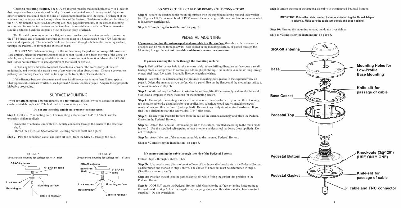
SRA-50 antenna
Mounting Holes for Low-Profile Base Mounting
Base
Base Gasket
Pedestal Top
Pedestal Bottom
Pedestal Gasket
DO NOT CUT THE CABLE OR REMOVE THE CONNECTOR!
Step 3: Secure the antenna to the mounting surface with the supplied retaining nut and lock washer(see Figures 1 & 2). A small bead of RTV around the outer edge of the antenna base is recommendedto insure a watertight seal.
Skip to “Completing the installation” on page 5.
PEDESTAL MOUNTINGIf you are attaching the antenna/pedestal assembly to a flat surface, the cable with its connectorattached can be routed through a 9/16” hole drilled in the mounting surface, or passed through theMounting Flange. Do not cut the cable and do not remove the connector.
If you are running the cable through the mounting surface:
Step 1: Drill a 9/16” center hole for the antenna cable. When drilling fiberglass surfaces, use a smallbackup block of scrap wood to control push-through splintering. Use caution to avoid drilling throughor near fuel lines, fuel tanks, hydraulic lines, or electrical wiring.
Step 2:
Step 3: While holding the Pedestal Gasket to the surface, lift off the assembly and use the PedestalGasket as a template to mark locations for the mounting screws.
Step 4: The supplied mounting screws will accommodate most surfaces. If you find them too long,too short, or otherwise unsuitable for your application, substitute wood screws, machine screws/washers/nuts, or other hardware (not supplied). Be sure to use only stainless steel hardware. If youfind it too difficult to start the screws, drill 7/64” pilot holes.
Step 5:
Step 6a: Attach the Pedestal Bottom and gasket to the surface, oriented according to the mark madein step 2. Use the supplied self-tapping screws or other stainless steel hardware (not supplied). Donot overtighten.
Step 7a: Attach the rest of the antenna assembly to the mounted Pedestal Bottom.
Skip to “Completing the installation” on page 5.
If you are running the cable through the side of the Pedestal Bottom:
Follow Steps 2 through 5 above. Then:
Step 6b: Use needle nose pliers to break off one of the three cable knockouts in the Pedestal Bottom,as determined and marked in step 2 above. The choice of knockout must be determined in step 2.(See illustration on page 2)
Step 7b: Position the cable in the gasket’s knife-slit while fitting the gasket into position in thePedestal Bottom.
Step 8: LOOSELY attach the Pedestal Bottom with Gasket to the surface, orienting it according tothe mark made in step 2. Use the supplied self-tapping screws or other stainless steel hardware (notsupplied). Do not overtighten.
FIGURE 1Direct surface mounting for surfaces up to 1/4” thick Direct surface mounting for surfaces 1/4” – 1” thick
FIGURE 2
SRA-50 antenna
Mounting surface
6” SRA-50cable
ExtensionShaft
SRA-50 antenna
Retaining nut
Lock washer
Cable to receiver
Retaining nut
Lock washer
Cable to receiver
Mounting surface
6” SRA-50 cable
Knife-slit forpassage of cable
6” cable and TNC connector
Step 9: Attach the rest of the antenna assembly to the mounted Pedestal Bottom.
Step 10: Firm up the mounting screws, but do not over tighten.
Skip to “Completing the installation” on page 5.
Knockouts (3@120°)(USE ONLY ONE)
Knife-slit forpassage of cable
432
Assemble the antenna along the provided mounting parts just as in the exploded view on page 4. Orient the antenna as you prefer. Mark a pencil line on the flange and the mounting surface to serve as an index in step 6b.
Unscrew the Pedestal Bottom from the rest of the antenna assembly and place the Pedestal Gasket in the Pedestal Bottom.
When mounting to a flat surface using the pedestal or low-profile Antenna Base options, orient the Pedestal/Antenna Base so that its cable exit faces the rear of the vessel or vehicle, away from oncoming wind due to normal vessel or vehicle motion. Mount the SRA-50 so that it does not interfere with safe operation of the vessel or vehicle.