Embed Size (px)
Citation preview

1
INSTRUCTION MANUAL DIN rail mounting type digital indicating limit controller DCL-33A-R/M T6119
DCL33T6119E1 2007.03 To prevent accidents arising from the misuse of this limit controller, please ensure the operator receives this manual.
Safety precautions (Be sure to read these precautions before using our products.) The safety precautions are classified into categories: “Warning” and “Caution”. Depending on circumstances, procedures indicated by Caution may cause serious results, so be sure to follow the directions for usage.
Warning
Warning • To prevent an electric shock or fire, only Shinko or other qualified service personnel may handle the inner
assembly. • To prevent an electric shock, fire or damage to the instrument, parts replacement may only be undertaken by our or other qualified service personnel.
Safety precautions • To ensure safe and correct use, thoroughly read and understand this manual before using this instrument. • This instrument is intended to be used for industrial machinery, machine tools and measuring equipment. Verify
correct usage after consulting purpose of use with our agency or main office. (Never use this instrument for medical purposes with which human lives are involved.)
• External protection devices such as protection equipment against excessive temperature rise, etc. must be installed, as malfunction of this product could result in serious damage to the system or injury to personnel. Also proper periodic maintenance is required.
• This instrument must be used under the conditions and environment described in this manual. We do not accept liability for any injury, loss of life or damage occurring due to the instrument being used under conditions not otherwise stated in this manual.
Caution with respect to Export Trade Control Ordinance To avoid this instrument from being used as a component in, or as being utilized in the manufacture of weapons of mass destruction (i.e. military applications, military equipment, etc.), please investigate the end users and the final use of this instrument. In the case of resale, ensure that this instrument is not illegally exported.
Caution • This instrument should be used according to the specifications described in the manual.
If it is not used according to the specifications, it may malfunction or cause fire. • Be sure to follow the warnings, cautions and notices. Not doing so could cause serious injury or malfunction. • Specifications of the DCL-33A and the contents of this instruction manual are subject to change without notice.• This instrument is designed to be installed on a DIN rail. If it is not, measures must be taken to ensure that
the operator cannot touch power terminals or other high voltage sections. • Be sure to turn the power supply to the instrument OFF before cleaning this instrument. • Use a soft, dry cloth when cleaning the instrument. (Alcohol based substances may tarnish or deface the unit.) • As the display section is vulnerable, do not strike or scratch it with a hard object. • Any unauthorized transfer or copying of this document, in part or in whole, is prohibited. • Shinko Technos CO., LTD. is not liable for any damages or secondary damages incurred as a result of using
this product, including any indirect damages.
Caution
Procedures which may lead to dangerous conditions and cause death or seriousinjury, if not carried out properly.
Procedures which may lead to dangerous conditions and cause superficial to mediuminjury or physical damage or may degrade or damage the product, if not carried outproperly.
2
1. Model 1.1 Model
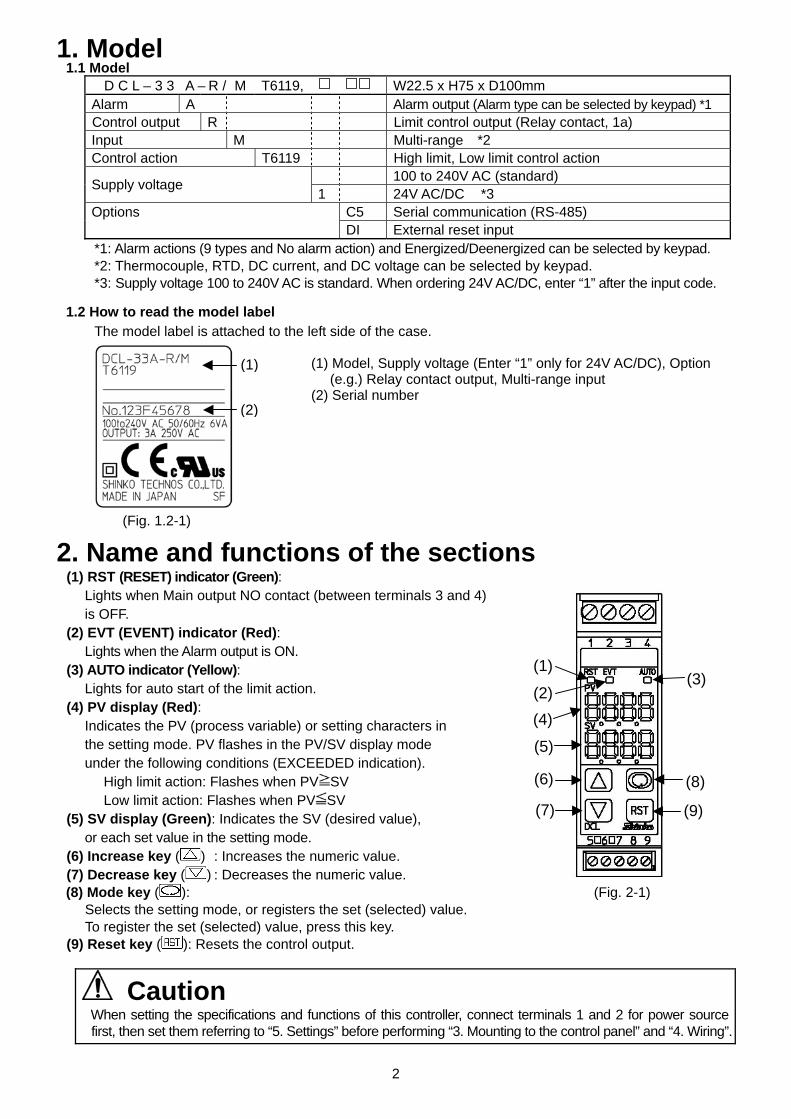
D C L – 3 3 A – R / M T6119, W22.5 x H75 x D100mm Alarm A Alarm output (Alarm type can be selected by keypad) *1 Control output R Limit control output (Relay contact, 1a) Input M Multi-range *2 Control action T6119 High limit, Low limit control action
100 to 240V AC (standard) Supply voltage 1 24V AC/DC *3
C5 Serial communication (RS-485) Options DI External reset input
*1: Alarm actions (9 types and No alarm action) and Energized/Deenergized can be selected by keypad. *2: Thermocouple, RTD, DC current, and DC voltage can be selected by keypad. *3: Supply voltage 100 to 240V AC is standard. When ordering 24V AC/DC, enter “1” after the input code.
1.2 How to read the model label
The model label is attached to the left side of the case. (1) Model, Supply voltage (Enter “1” only for 24V AC/DC), Option (e.g.) Relay contact output, Multi-range input (2) Serial number (Fig. 1.2-1)
2. Name and functions of the sections (1) RST (RESET) indicator (Green):
Lights when Main output NO contact (between terminals 3 and 4) is OFF.
(2) EVT (EVENT) indicator (Red): Lights when the Alarm output is ON.
(3) AUTO indicator (Yellow): Lights for auto start of the limit action.
(4) PV display (Red): Indicates the PV (process variable) or setting characters in the setting mode. PV flashes in the PV/SV display mode under the following conditions (EXCEEDED indication).
High limit action: Flashes when PV SV Low limit action: Flashes when PV SV
(5) SV display (Green): Indicates the SV (desired value), or each set value in the setting mode.
(6) Increase key ( ) : Increases the numeric value. (7) Decrease key ( ) : Decreases the numeric value. (8) Mode key ( ): (Fig. 2-1)
Selects the setting mode, or registers the set (selected) value. To register the set (selected) value, press this key.
(9) Reset key ( ): Resets the control output.
Caution When setting the specifications and functions of this controller, connect terminals 1 and 2 for power sourcefirst, then set them referring to “5. Settings” before performing “3. Mounting to the control panel” and “4. Wiring”.
(1)
(2)
(1)
(5)
(3)
(4)
(7)
(8)
(2)
(6)
(9)
3
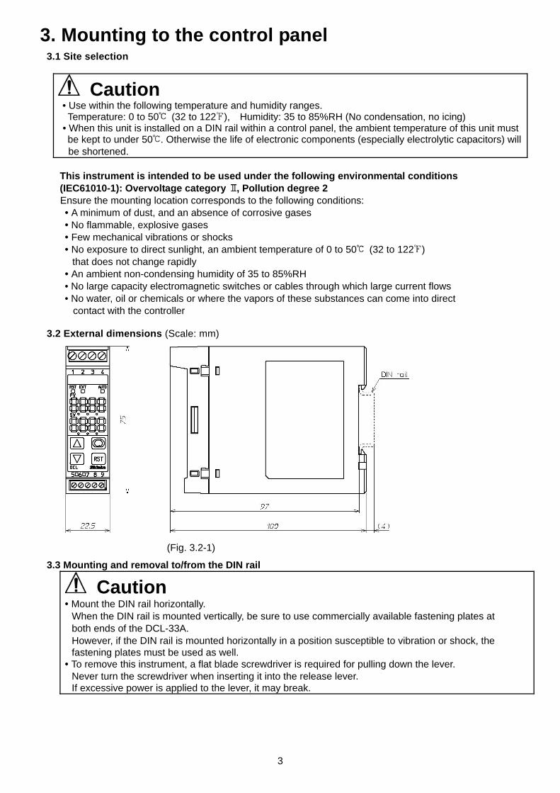
3. Mounting to the control panel 3.1 Site selection
Caution • Use within the following temperature and humidity ranges. Temperature: 0 to 50 (32 to 122 ), Humidity: 35 to 85%RH (No condensation, no icing) • When this unit is installed on a DIN rail within a control panel, the ambient temperature of this unit must be kept to under 50 . Otherwise the life of electronic components (especially electrolytic capacitors) will
be shortened.
This instrument is intended to be used under the following environmental conditions (IEC61010-1): Overvoltage category , Pollution degree 2
Ensure the mounting location corresponds to the following conditions: • A minimum of dust, and an absence of corrosive gases • No flammable, explosive gases
• Few mechanical vibrations or shocks • No exposure to direct sunlight, an ambient temperature of 0 to 50 (32 to 122 )
that does not change rapidly • An ambient non-condensing humidity of 35 to 85%RH • No large capacity electromagnetic switches or cables through which large current flows • No water, oil or chemicals or where the vapors of these substances can come into direct
contact with the controller
3.2 External dimensions (Scale: mm) (Fig. 3.2-1)
3.3 Mounting and removal to/from the DIN rail
Caution • Mount the DIN rail horizontally.
When the DIN rail is mounted vertically, be sure to use commercially available fastening plates at both ends of the DCL-33A. However, if the DIN rail is mounted horizontally in a position susceptible to vibration or shock, the fastening plates must be used as well.
• To remove this instrument, a flat blade screwdriver is required for pulling down the lever. Never turn the screwdriver when inserting it into the release lever. If excessive power is applied to the lever, it may break.
4
• Recommended fastening plate Manufacturer Model
Omron corporation End plate PFP-M IDEC corporation Fastening plate BNL6 Matsushita electric works, LTD. Fastening plate ATA4806
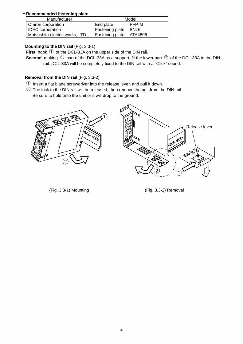
Mounting to the DIN rail (Fig. 3.3-1) First, hook 1 of the DCL-33A on the upper side of the DIN rail. Second, making 1 part of the DCL-33A as a support, fit the lower part 2 of the DCL-33A to the DIN
rail. DCL-33A will be completely fixed to the DIN rail with a “Click” sound. Removal from the DIN rail (Fig. 3.3-2)
1 Insert a flat blade screwdriver into the release lever, and pull it down. 2 The lock to the DIN rail will be released, then remove the unit from the DIN rail.
Be sure to hold onto the unit or it will drop to the ground.
(Fig. 3.3-1) Mounting (Fig. 3.3-2) Removal
12
Release lever
2
1
5
4. Wiring Warning
Turn the power supply to the instrument OFF before wiring or checking it. Working or touching the terminal with the power switched ON may result in severe injury or death due to Electric Shock.
Caution • Do not leave bits of wire in the DCL-33A when wiring, because they could cause a fire or malfunction. • Insert the connecting cable into the designated connector securely. Not doing so could cause malfunction due to imperfect contact. • Connect the AC power to the designated terminal as is written in this instruction manual. Otherwise it may burn and damage the DCL-33A. • Tighten the terminal screw with the specified torque. Excessive force could damage the terminal screw and deface the case. • Use a thermocouple and compensating lead wire that corresponds to the sensor input specification of this unit. • Use the 3-wire RTD that corresponds to the sensor input specification of this unit. • When using DC voltage and current inputs, be careful not to confuse polarity when wiring. • For a 24V AC/DC power source, do not confuse polarity when using direct current (DC). • Keep input wires (Thermocouple, RTD, etc.) away from power source and load wires when wiring. • Do not apply a commercial power source to the sensor connected to the input terminal nor allow the power source to come into contact with the sensor. • To prevent the unit from harmful effects of unexpected level noise, it is recommended that a surge absorber be installed between the electromagnetic switch coils.
• This unit does not have a built-in power switch, circuit breaker or fuse. Therefore it is necessary to install them in the circuit near the external unit. (Recommended fuse: Time-lag fuse, Rated voltage 250V AC, Rated current 2A)
When using ferrules, use the following ferrules and crimping pliers made by Phoenix Contact GMBH &CO.
• Recommended ferrules and tightening torque Terminal number
Terminal screw
Ferrules with insulation sleeve
Conductor cross sections Tightening torque Crimping pliers
AI 0.25-8 YE 0.2 to 0.25mm2 AI 0.34-8 TQ 0.25 to 0.34mm2 AI 0.5-8 WH 0.34 to 0.5mm2 AI 0.75-8 GY 0.5 to 0.75mm2 AI 1.0-8 RD 0.75 to 1.0mm2
1 to 4 M2.6
AI 1.5-8 BK 1.0 to 1.5mm2
0.5 to 0.6N•m
AI 0.25-8 YE 0.2 to 0.25mm2 AI 0.34-8 TQ 0.25 to 0.34mm2
5 to 9 M2.0
AI 0.5-8 WH 0.34 to 0.5mm2
0.22 to 0.25N•m
CRIMPFOX ZA3 CRIMPFOX UD6
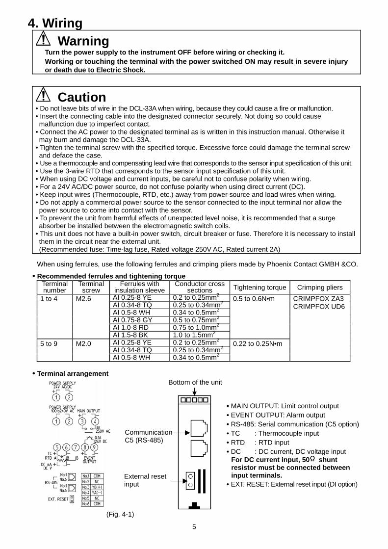
• Terminal arrangement
• MAIN OUTPUT: Limit control output • EVENT OUTPUT: Alarm output • RS-485: Serial communication (C5 option) • TC : Thermocouple input • RTD : RTD input • DC : DC current, DC voltage input
For DC current input, 50 shunt resistor must be connected between input terminals.
• EXT. RESET: External reset input (DI option)
(Fig. 4-1)
Bottom of the unit
CommunicationC5 (RS-485)
External reset input
6
5. Settings 5.1 Operation flowchart
PV/SV display
[Main setting mode]
POWER ON
Press the .
Alarm value
PV SV Value
• Set the value with the or key.• Not available if is selected during Alarm type selection
SV PV SV SV
• Set the value with the or key. Set value lock
PV SVSelection
• Make a selection with the or key.• Be sure to select Lock 3 when using Serial communication.
Reverts to the PV/SV display.
Maximum(Minimum) value *1 PV ( )
SV Max. value (Min. value)
EXCEEDED indication duration time PV SV Time
[Display mode]
Sensor correction PV SV Value
• Set the value with the or key.
Communication protocol PV SV Selection
• Make a selection with the or key.
Instrument number PV SV Value
• Set the value with the or key.
(7)
Press the for 3sec while holding down the . Press the for 3sec while holding down the .
[Sub setting mode]
*1 Maximum (or Minimum) value will be indicated if high (or low) limit control action is selected during High/Low limit controlselection in the Setup mode.
: This means that if the key is pressed, the set value is saved, and the controller proceeds to the next setting item.
• Setting items with dotted lines are optional andthey appear only when the options are added.
• If the key is pressed for approx. 3sec, thecontroller reverts to the PV/SV display mode from any mode.
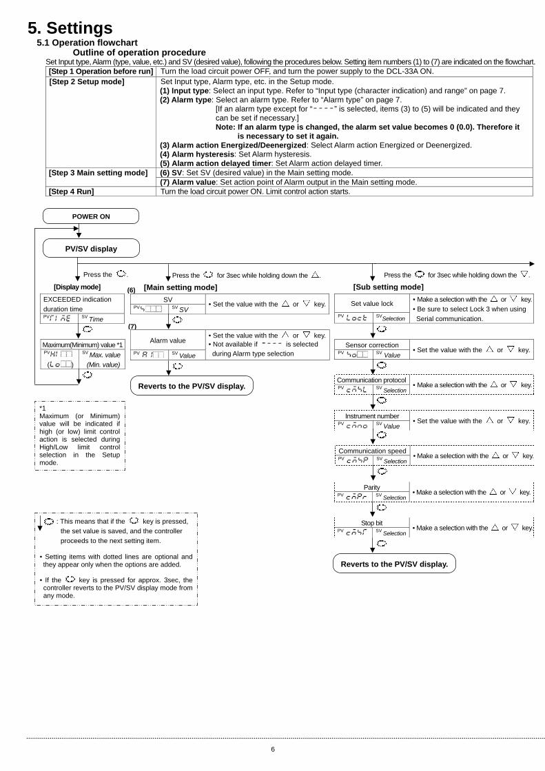
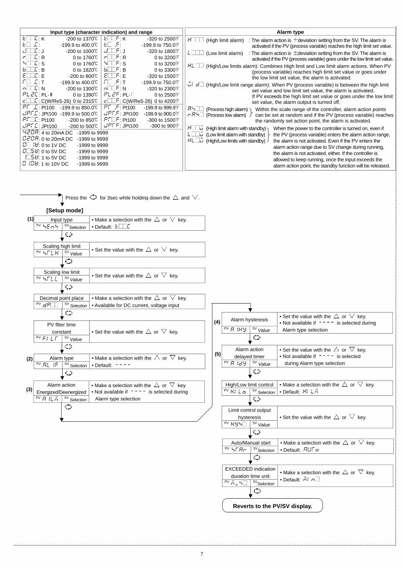
Outline of operation procedure Set Input type, Alarm (type, value, etc.) and SV (desired value), following the procedures below. Setting item numbers (1) to (7) are indicated on the flowchart. [Step 1 Operation before run] Turn the load circuit power OFF, and turn the power supply to the DCL-33A ON. [Step 2 Setup mode]
Set Input type, Alarm type, etc. in the Setup mode. (1) Input type: Select an input type. Refer to “Input type (character indication) and range” on page 7. (2) Alarm type: Select an alarm type. Refer to “Alarm type” on page 7. [If an alarm type except for “ ” is selected, items (3) to (5) will be indicated and they can be set if necessary.]
Note: If an alarm type is changed, the alarm set value becomes 0 (0.0). Therefore it is necessary to set it again.
(3) Alarm action Energized/Deenergized: Select Alarm action Energized or Deenergized. (4) Alarm hysteresis: Set Alarm hysteresis. (5) Alarm action delayed timer: Set Alarm action delayed timer. (6) SV: Set SV (desired value) in the Main setting mode. [Step 3 Main setting mode] (7) Alarm value: Set action point of Alarm output in the Main setting mode.
[Step 4 Run] Turn the load circuit power ON. Limit control action starts.
(6)
Communication speed PV SV Selection
• Make a selection with the or key.
Parity PV SV Selection
• Make a selection with the or key.
Stop bit PV SV Selection
• Make a selection with the or key.
Reverts to the PV/SV display.
7
Scaling low limit PV SV Value
• Set the value with the or key.
Scaling high limit PV SV Value
• Set the value with the or key.
Decimal point place PV SV Selection
• Make a selection with the or key. • Available for DC current, voltage input
PV filter time constant
PV SV Value • Set the value with the or key.
Limit control output hysteresis
PV SV Value • Set the value with the or key.
[Setup mode]
Auto/Manual start PV SVSelection
• Make a selection with the or key. • Default:
EXCEEDED indicationduration time unit
PV SVSelection
• Make a selection with the or key. • Default:
Reverts to the PV/SV display.
Alarm type PV SV Selection
• Make a selection with the or key. • Default:
Alarm hysteresis PV SV Value
• Set the value with the or key. • Not available if is selected during
Alarm type selection
Alarm action Energized/Deenergized PV SV Selection
• Make a selection with the or key. • Not available if is selected during
Alarm type selection
Alarm action delayed timer
PV SV Value
• Set the value with the or key. • Not available if is selected
during Alarm type selection
High/Low limit control PV SV Selection
• Make a selection with the or key. • Default:
(2)
Input type (character indication) and range : K -200 to 1370 : -199.9 to 400.0 : J -200 to 1000 : R 0 to 1760 : S 0 to 1760 : B 0 to 1820 : E -200 to 800 : T -199.9 to 400.0 : N -200 to 1300 : PL- 0 to 1390 : C(W/Re5-26) 0 to 2315
: K -320 to 2500: -199.9 to 750.0: J -320 to 1800: R 0 to 3200: S 0 to 3200: B 0 to 3300: E -320 to 1500: T -199.9 to 750.0: N -320 to 2300: PL- 0 to 2500: C(W/Re5-26) 0 to 4200
: Pt100 -199.9 to 850.0 : JPt100 -199.9 to 500.0 : Pt100 -200 to 850 : JPt100 -200 to 500
: Pt100 -199.9 to 999.9: JPt100 -199.9 to 900.0: Pt100 -300 to 1500: JPt100 -300 to 900
: 4 to 20mA DC -1999 to 9999 : 0 to 20mA DC -1999 to 9999 : 0 to 1V DC -1999 to 9999 : 0 to 5V DC -1999 to 9999 : 1 to 5V DC -1999 to 9999 : 1 to 10V DC -1999 to 9999
Alarm type (High limit alarm) : The alarm action is deviation setting from the SV. The alarm is
activated if the PV (process variable) reaches the high limit set value. (Low limit alarm) : The alarm action is deviation setting from the SV. The alarm is
activated if the PV (process variable) goes under the low limit set value. (High/Low limits alarm): Combines High limit and Low limit alarm actions. When PV
(process variable) reaches high limit set value or goes under the low limit set value, the alarm is activated.
(High/Low limit range alarm): When PV (process variable) is between the high limit set value and low limit set value, the alarm is activated. If PV exceeds the high limit set value or goes under the low limit set value, the alarm output is turned off.
(Process high alarm) Within the scale range of the controller, alarm action points (Process low alarm) can be set at random and if the PV (process variable) reaches
the randomly set action point, the alarm is activated. (High limit alarm with standby) When the power to the controller is turned on, even if (Low limit alarm with standby) the PV (process variable) enters the alarm action range, (High/Low limits with standby) the alarm is not activated. Even if the PV enters the
alarm action range due to SV change during running, the alarm is not activated, either. If the controller is allowed to keep running, once the input exceeds the alarm action point, the standby function will be released.
Input type PV SVSelection
• Make a selection with the or key. • Default:
Press the for 3sec while holding down the and .
(3)
(5)
(1)
(4)
8
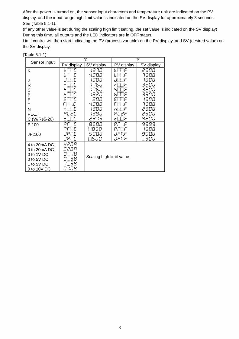
After the power is turned on, the sensor input characters and temperature unit are indicated on the PV display, and the input range high limit value is indicated on the SV display for approximately 3 seconds. See (Table 5.1-1). (If any other value is set during the scaling high limit setting, the set value is indicated on the SV display) During this time, all outputs and the LED indicators are in OFF status. Limit control will then start indicating the PV (process variable) on the PV display, and SV (desired value) on the SV display.
(Table 5.1-1) Sensor input PV display SV display PV display SV display
K J R S B E T N PL- C (W/Re5-26)
Pt100 JPt100
4 to 20mA DC 0 to 20mA DC 0 to 1V DC 0 to 5V DC 1 to 5V DC 0 to 10V DC
Scaling high limit value
9
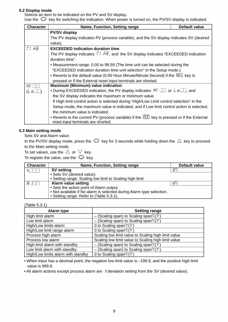
5.2 Display mode Selects an item to be indicated on the PV and SV display. Use the key for switching the indication. When power is turned on, the PV/SV display is indicated.
Character Name, Function, Setting range Default value PV/SV display
The PV display indicates PV (process variable), and the SV display indicates SV (desired value).
EXCEEDED indication duration time The PV display indicates , and the SV display indicates “EXCEEDED indication duration time”. • Measurement range: 0.00 to 99.59 (The time unit can be selected during the “EXCEEDED indication duration time unit selection” in the Setup mode.) • Reverts to the default value (0.00 Hour.Minute/Minute.Second) if the key is
pressed or if the External reset input terminals are shorted.
( ) Maximum (Minimum) value indication • During EXCEEDED indication, the PV display indicates or , and
the SV display indicates the maximum or minimum value. If High limit control action is selected during “High/Low Limit control selection” in the Setup mode, the maximum value is indicated, and if Low limit control action is selected, the minimum value is indicated.
• Reverts to the current PV (process variable) if the key is pressed or if the External reset input terminals are shorted.
5.3 Main setting mode
Sets SV and Alarm value. In the PV/SV display mode, press the key for 3 seconds while holding down the key to proceed to the Main setting mode. To set values, use the or key. To register the value, use the key.
Character Name, Function, Setting range Default value SV setting 0
• Sets SV (desired value). • Setting range: Scaling low limit to Scaling high limit Alarm value setting 0
• Sets the action point of Alarm output. • Not available if No alarm is selected during Alarm type selection. • Setting range: Refer to (Table 5.3-1).
(Table 5.3-1)
Alarm type Setting range High limit alarm – (Scaling span) to Scaling span ( ) Low limit alarm – (Scaling span) to Scaling span ( ) High/Low limits alarm 0 to Scaling span ( ) High/Low limit range alarm 0 to Scaling span ( ) Process high alarm Scaling low limit value to Scaling high limit value Process low alarm Scaling low limit value to Scaling high limit value High limit alarm with standby – (Scaling span) to Scaling span ( ) Low limit alarm with standby – (Scaling span) to Scaling span ( ) High/Low limits alarm with standby 0 to Scaling span ( )
• When input has a decimal point, the negative low limit value is –199.9, and the positive high limit value is 999.9.
• All alarm actions except process alarm are deviation setting from the SV (desired value).
10
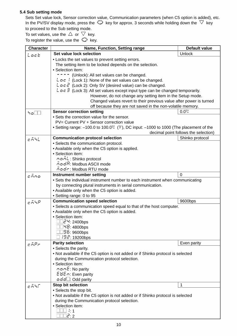
5.4 Sub setting mode Sets Set value lock, Sensor correction value, Communication parameters (when C5 option is added), etc. In the PV/SV display mode, press the key for approx. 3 seconds while holding down the key to proceed to the Sub setting mode. To set values, use the or key. To register the value, use the key.
Character Name, Function, Setting range Default value Set value lock selection Unlock • Locks the set values to prevent setting errors.
The setting item to be locked depends on the selection. • Selection item:
(Unlock): All set values can be changed. (Lock 1): None of the set values can be changed. (Lock 2): Only SV (desired value) can be changed. (Lock 3): All set values except input type can be changed temporarily.
However, do not change any setting item in the Setup mode. Changed values revert to their previous value after power is turned off because they are not saved in the non-volatile memory.
Sensor correction setting 0.0 • Sets the correction value for the sensor.
PV= Current PV + Sensor correction value • Setting range: –100.0 to 100.0 ( ), DC input: –1000 to 1000 (The placement of the
decimal point follows the selection) Communication protocol selection Shinko protocol • Selects the communication protocol. • Available only when the C5 option is applied. • Selection item:
: Shinko protocol : Modbus ASCII mode : Modbus RTU mode
Instrument number setting 0 • Sets the individual instrument number to each instrument when communicating
by connecting plural instruments in serial communication. • Available only when the C5 option is added. • Setting range: 0 to 95 Communication speed selection 9600bps • Selects a communication speed equal to that of the host computer. • Available only when the C5 option is added. • Selection item:
: 2400bps : 4800bps : 9600bps : 19200bps
Parity selection Even parity • Selects the parity. • Not available if the C5 option is not added or if Shinko protocol is selected during the Communication protocol selection. • Selection item:
: No parity : Even parity : Odd parity
Stop bit selection 1 • Selects the stop bit. • Not available if the C5 option is not added or if Shinko protocol is selected during the Communication protocol selection. • Selection item:
: 1 : 2
11
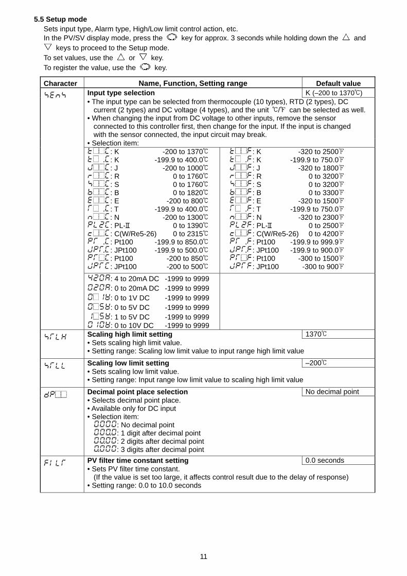
5.5 Setup mode Sets input type, Alarm type, High/Low limit control action, etc. In the PV/SV display mode, press the key for approx. 3 seconds while holding down the and
keys to proceed to the Setup mode. To set values, use the or key. To register the value, use the key.
Character Name, Function, Setting range Default value Input type selection K (–200 to 1370 ) • The input type can be selected from thermocouple (10 types), RTD (2 types), DC
current (2 types) and DC voltage (4 types), and the unit / can be selected as well. • When changing the input from DC voltage to other inputs, remove the sensor
connected to this controller first, then change for the input. If the input is changed with the sensor connected, the input circuit may break.
• Selection item: : K -200 to 1370 : K -199.9 to 400.0 : J -200 to 1000 : R 0 to 1760 : S 0 to 1760 : B 0 to 1820 : E -200 to 800 : T -199.9 to 400.0 : N -200 to 1300 : PL- 0 to 1390 : C(W/Re5-26) 0 to 2315 : Pt100 -199.9 to 850.0 : JPt100 -199.9 to 500.0 : Pt100 -200 to 850 : JPt100 -200 to 500
: K -320 to 2500 : K -199.9 to 750.0 : J -320 to 1800 : R 0 to 3200 : S 0 to 3200 : B 0 to 3300 : E -320 to 1500 : T -199.9 to 750.0 : N -320 to 2300 : PL- 0 to 2500 : C(W/Re5-26) 0 to 4200 : Pt100 -199.9 to 999.9 : JPt100 -199.9 to 900.0 : Pt100 -300 to 1500 : JPt100 -300 to 900
: 4 to 20mA DC -1999 to 9999 : 0 to 20mA DC -1999 to 9999 : 0 to 1V DC -1999 to 9999 : 0 to 5V DC -1999 to 9999 : 1 to 5V DC -1999 to 9999 : 0 to 10V DC -1999 to 9999
Scaling high limit setting 1370 • Sets scaling high limit value. • Setting range: Scaling low limit value to input range high limit value
Scaling low limit setting –200 • Sets scaling low limit value. • Setting range: Input range low limit value to scaling high limit value
Decimal point place selection No decimal point • Selects decimal point place. • Available only for DC input • Selection item:
: No decimal point : 1 digit after decimal point : 2 digits after decimal point : 3 digits after decimal point
PV filter time constant setting 0.0 seconds • Sets PV filter time constant.
(If the value is set too large, it affects control result due to the delay of response) • Setting range: 0.0 to 10.0 seconds
12
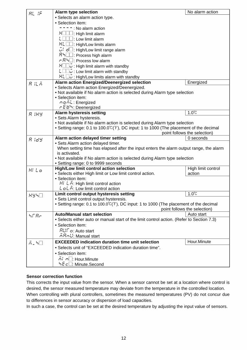
Alarm type selection No alarm action • Selects an alarm action type. • Selection item:
: No alarm action : High limit alarm : Low limit alarm : High/Low limits alarm : High/Low limit range alarm : Process high alarm : Process low alarm : High limit alarm with standby : Low limit alarm with standby : High/Low limits alarm with standby
Alarm action Energized/Deenergized selection Energized • Selects Alarm action Energized/Deenergized. • Not available if No alarm action is selected during Alarm type selection • Selection item:
: Energized : Deenergized
Alarm hysteresis setting 1.0 • Sets Alarm hysteresis. • Not available if No alarm action is selected during Alarm type selection • Setting range: 0.1 to 100.0 ( ), DC input: 1 to 1000 (The placement of the decimal point follows the selection) Alarm action delayed timer setting 0 seconds • Sets Alarm action delayed timer. When setting time has elapsed after the input enters the alarm output range, the alarm is activated.
• Not available if No alarm action is selected during Alarm type selection • Setting range: 0 to 9999 seconds High/Low limit control action selection • Selects either High limit or Low limit control action.
High limit control action
• Selection item: : High limit control action : Low limit control action
Limit control output hysteresis setting 1.0 • Sets Limit control output hysteresis. • Setting range: 0.1 to 100.0 ( ), DC input: 1 to 1000 (The placement of the decimal point follows the selection) Auto/Manual start selection Auto start • Selects either auto or manual start of the limit control action. (Refer to Section 7.3) • Selection item:
: Auto start : Manual start
EXCEEDED indication duration time unit selection Hour.Minute • Selects unit of “EXCEEDED indication duration time”. • Selection item:
: Hour.Minute : Minute.Second
Sensor correction function This corrects the input value from the sensor. When a sensor cannot be set at a location where control is desired, the sensor measured temperature may deviate from the temperature in the controlled location. When controlling with plural controllers, sometimes the measured temperatures (PV) do not concur due to differences in sensor accuracy or dispersion of load capacities. In such a case, the control can be set at the desired temperature by adjusting the input value of sensors.
13
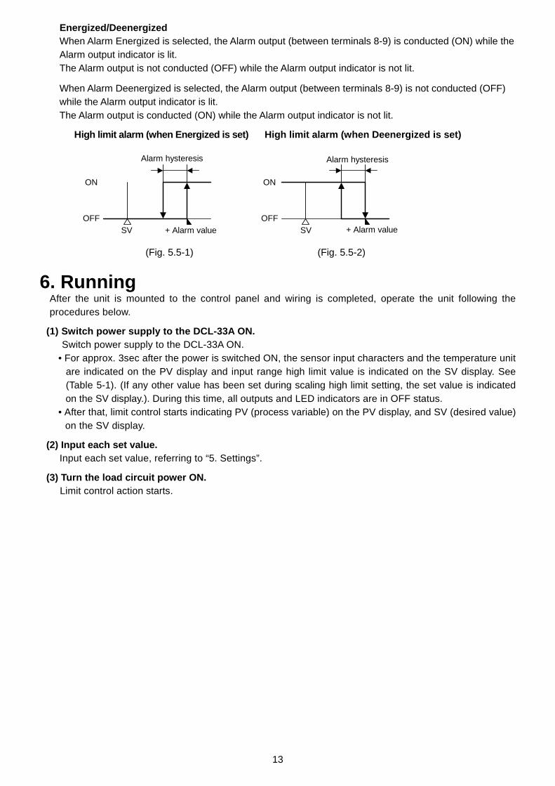
Energized/Deenergized When Alarm Energized is selected, the Alarm output (between terminals 8-9) is conducted (ON) while the Alarm output indicator is lit. The Alarm output is not conducted (OFF) while the Alarm output indicator is not lit.
When Alarm Deenergized is selected, the Alarm output (between terminals 8-9) is not conducted (OFF) while the Alarm output indicator is lit. The Alarm output is conducted (ON) while the Alarm output indicator is not lit.
High limit alarm (when Energized is set) High limit alarm (when Deenergized is set)
(Fig. 5.5-1) (Fig. 5.5-2) 6. Running
After the unit is mounted to the control panel and wiring is completed, operate the unit following the procedures below.
(1) Switch power supply to the DCL-33A ON. Switch power supply to the DCL-33A ON.
• For approx. 3sec after the power is switched ON, the sensor input characters and the temperature unit are indicated on the PV display and input range high limit value is indicated on the SV display. See (Table 5-1). (If any other value has been set during scaling high limit setting, the set value is indicated on the SV display.). During this time, all outputs and LED indicators are in OFF status.
• After that, limit control starts indicating PV (process variable) on the PV display, and SV (desired value) on the SV display.
(2) Input each set value. Input each set value, referring to “5. Settings”.
(3) Turn the load circuit power ON. Limit control action starts.
OFF
ON
Alarm hysteresis
SV + Alarm valueOFF
ON
SV + Alarm value
Alarm hysteresis
14
SV
PV
ON OFFLimit control output 3-4
ONOFF
Lit
Hysteresis
EXCEEDED indication(PV display)
RESET indicator
POWER OFF POWER ON
Flashing
Unlit Unlit
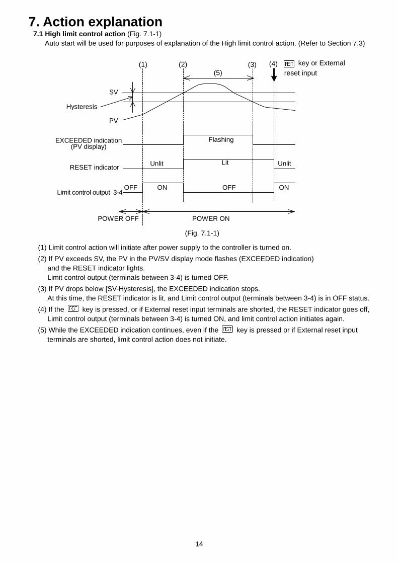
7. Action explanation 7.1 High limit control action (Fig. 7.1-1)
Auto start will be used for purposes of explanation of the High limit control action. (Refer to Section 7.3)
(Fig. 7.1-1)
(1) Limit control action will initiate after power supply to the controller is turned on. (2) If PV exceeds SV, the PV in the PV/SV display mode flashes (EXCEEDED indication)
and the RESET indicator lights. Limit control output (terminals between 3-4) is turned OFF.
(3) If PV drops below [SV-Hysteresis], the EXCEEDED indication stops. At this time, the RESET indicator is lit, and Limit control output (terminals between 3-4) is in OFF status.
(4) If the key is pressed, or if External reset input terminals are shorted, the RESET indicator goes off, Limit control output (terminals between 3-4) is turned ON, and limit control action initiates again.
(5) While the EXCEEDED indication continues, even if the key is pressed or if External reset input terminals are shorted, limit control action does not initiate.
(1) (2) (3) (4)(5)
key or Externalreset input
15
SV
PV
ON OFFLimit control output 3-4
ONOFF
POWER ONPOWER OFF
EXCEEDED indication(PV display)
Hysteresis
RESET indicator
Flashing
UnlitUnlit Lit
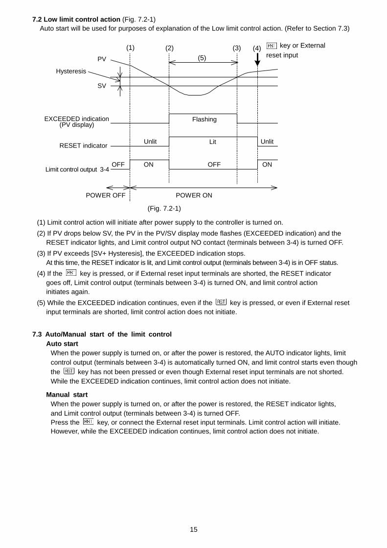
7.2 Low limit control action (Fig. 7.2-1) Auto start will be used for purposes of explanation of the Low limit control action. (Refer to Section 7.3)
(Fig. 7.2-1)
(1) Limit control action will initiate after power supply to the controller is turned on. (2) If PV drops below SV, the PV in the PV/SV display mode flashes (EXCEEDED indication) and the
RESET indicator lights, and Limit control output NO contact (terminals between 3-4) is turned OFF. (3) If PV exceeds [SV+ Hysteresis], the EXCEEDED indication stops.
At this time, the RESET indicator is lit, and Limit control output (terminals between 3-4) is in OFF status. (4) If the key is pressed, or if External reset input terminals are shorted, the RESET indicator
goes off, Limit control output (terminals between 3-4) is turned ON, and limit control action initiates again.
(5) While the EXCEEDED indication continues, even if the key is pressed, or even if External reset input terminals are shorted, limit control action does not initiate.
7.3 Auto/Manual start of the limit control
Auto start When the power supply is turned on, or after the power is restored, the AUTO indicator lights, limit control output (terminals between 3-4) is automatically turned ON, and limit control starts even though the key has not been pressed or even though External reset input terminals are not shorted. While the EXCEEDED indication continues, limit control action does not initiate.
Manual start When the power supply is turned on, or after the power is restored, the RESET indicator lights, and Limit control output (terminals between 3-4) is turned OFF. Press the key, or connect the External reset input terminals. Limit control action will initiate. However, while the EXCEEDED indication continues, limit control action does not initiate.
key or Externalreset input
(1) (2) (3) (4)(5)

16
: Alarm output terminals 8-9 ON
: Alarm output terminals 8-9 ON or OFF
: Alarm output terminals 8-9 OFF
: The standby functions.
Alarmaction
Alarmoutput
+ side
OFF
ON
OFF
ON
OFF
ON
OFF
ON
OFF
ON
OFF
ON
OFF
ON
OFF
ON
OFF
ON
High/Low limits alarm
High/Low limit range alarm
Low limit alarm
Process high alarm Process low alarm
Alarm hysteresis
+ Alarm valueAlarm value SV
High limit alarm
High limit alarm with standby Low limit alarm with standby
Alarm hysteresis
SV
SVSVSV
High/Low limits alarm with standby
A1 action
Alarmaction
A1 output
Alarmoutput
- side
+ side
- side
+ side
- side
+ side
- side
SVSV
Alarm hysteresis
Alarm hysteresis
Alarm hysteresis
+ Alarm value
Alarm hysteresis
Alarm hysteresis Alarm hysteresis
Alarm hysteresis
Alarm value + Alarm value
Alarm valueAlarm valueAlarm value
Alarm value Alarm value + Alarm value Alarm value Alarm value
Alarm value Alarm value
Alarm value
7.4 Alarm action 10. Specifications
10.1 Standard specifications Model : DIN rail mounting type limit controller Mounting : DIN rail mounting Setting : Input system using membrane sheet key Display PV display : Red LED 4 digits, character size 7.4 x 4.0mm (H x W) SV display : Green LED 4 digits, character size 7.4 x 4.0mm (H x W) Input Thermocouple : K, J, R, S, B, E, T, N, PL- , C (W/Re5-26) External resistance: 100 or less
However, for thermocouple B, external resistance, 40 or less RTD : Pt100, JPt100, 3-wire system Allowable input lead wire resistance (10 or less per wire) DC current : 0 to 20mA DC, 4 to 20mA DC, input impedance 50 Connect 50 shunt resistor (sold separately) between input terminals 5 and 6. Allowable input current: 50mA or less
0 to 1V DC 0 to 5V DC, 1 to 5V DC, 0 to 10V DC
Input impedance 1M or more 100k or more Allowable input voltage 5V or less 15V or less Allowable signal sourceresistance 2k or less 100 or less
Accuracy (Setting and Indication) Thermocouple : Within 0.2% of input span 1 digit, or within 2 (4 ) whichever is greater
R, S inputs, 0 to 200 (0 to 400 ): Within 6 (12 ) B input, 0 to 300 (0 to 600 ): Accuracy is not guaranteed. K, J, E, T, N input, less than 0 (32 ): Within 0.4% of input span 1 digit
RTD : Within 0.1% of input span 1 digit, or within 1 (2 ) whichever is greater DC voltage : Within 0.2% of input span 1 digit DC current : Within 0.2% of input span 1 digit
Input sampling period : 0.25 seconds
• EVT indicator lights when alarm output terminals between 8-9 are ON, and goes off when alarm output terminals between 8-9 are OFF.
DC voltage :
17
EVTEXT. input
Input
CPU
Insulated
Limit control outputPower supply
Communication
5 9876
431 2
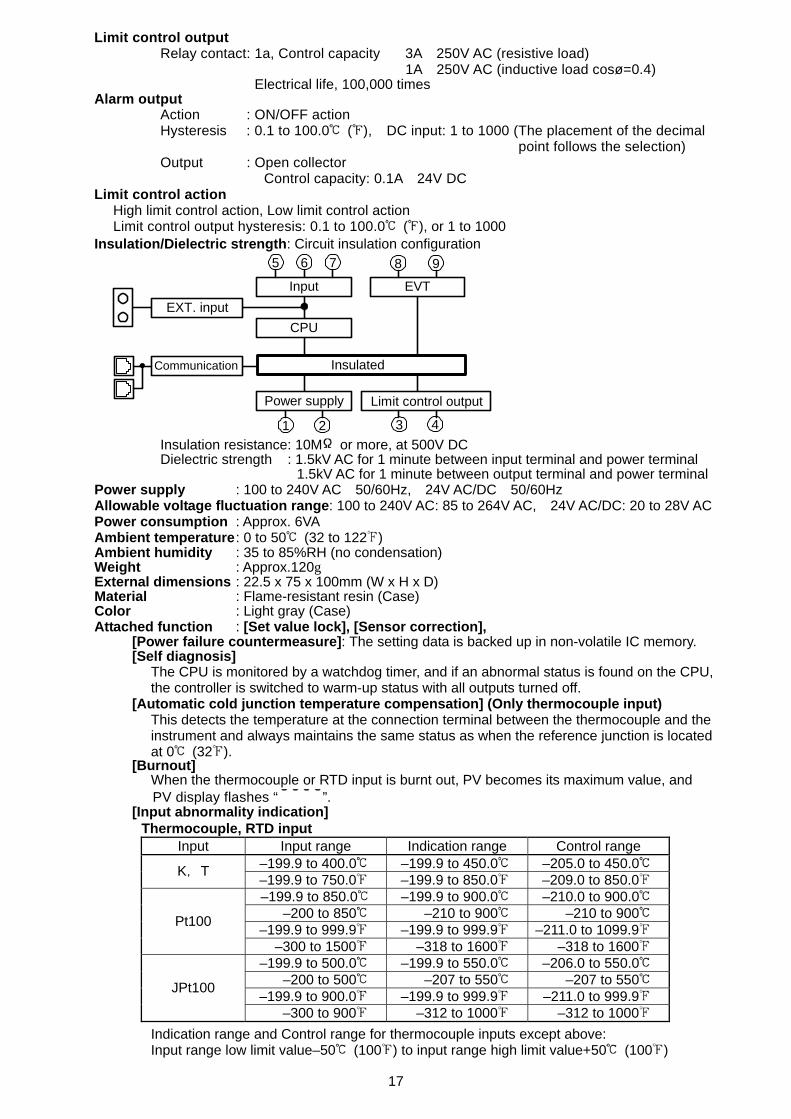
Limit control output Relay contact : 1a, Control capacity 3A 250V AC (resistive load) 1A 250V AC (inductive load cosø=0.4) Electrical life, 100,000 times
Alarm output Action : ON/OFF action
Hysteresis : 0.1 to 100.0 ( ), DC input: 1 to 1000 (The placement of the decimal point follows the selection)
Output : Open collector Control capacity: 0.1A 24V DC
Limit control action High limit control action, Low limit control action Limit control output hysteresis: 0.1 to 100.0 ( ), or 1 to 1000
Insulation/Dielectric strength: Circuit insulation configuration Insulation resistance: 10M or more, at 500V DC Dielectric strength : 1.5kV AC for 1 minute between input terminal and power terminal 1.5kV AC for 1 minute between output terminal and power terminal
Power supply : 100 to 240V AC 50/60Hz, 24V AC/DC 50/60Hz Allowable voltage fluctuation range: 100 to 240V AC: 85 to 264V AC, 24V AC/DC: 20 to 28V AC Power consumption : Approx. 6VA Ambient temperature : 0 to 50 (32 to 122 ) Ambient humidity : 35 to 85%RH (no condensation) Weight : Approx.120g External dimensions : 22.5 x 75 x 100mm (W x H x D) Material : Flame-resistant resin (Case) Color : Light gray (Case) Attached function : [Set value lock], [Sensor correction],
[Power failure countermeasure]: The setting data is backed up in non-volatile IC memory. [Self diagnosis]
The CPU is monitored by a watchdog timer, and if an abnormal status is found on the CPU, the controller is switched to warm-up status with all outputs turned off.
[Automatic cold junction temperature compensation] (Only thermocouple input) This detects the temperature at the connection terminal between the thermocouple and the instrument and always maintains the same status as when the reference junction is located at 0 (32 ).
[Burnout] When the thermocouple or RTD input is burnt out, PV becomes its maximum value, and PV display flashes “ ”.
[Input abnormality indication] Thermocouple, RTD input
Input Input range Indication range Control range –199.9 to 400.0 –199.9 to 450.0 –205.0 to 450.0 K,T –199.9 to 750.0 –199.9 to 850.0 –209.0 to 850.0
–199.9 to 850.0 –199.9 to 900.0 –210.0 to 900.0 –200 to 850 –210 to 900 –210 to 900 –199.9 to 999.9 –199.9 to 999.9 –211.0 to 1099.9 Pt100
–300 to 1500 –318 to 1600 –318 to 1600 –199.9 to 500.0 –199.9 to 550.0 –206.0 to 550.0 –200 to 500 –207 to 550 –207 to 550 –199.9 to 900.0 –199.9 to 999.9 –211.0 to 999.9 JPt100
–300 to 900 –312 to 1000 –312 to 1000 Indication range and Control range for thermocouple inputs except above: Input range low limit value–50 (100 ) to input range high limit value+50 (100 )

18
Output statusContents and Indication 3 - 4 Overscale: Measured value has exceeded Indication range high limit value. " " flashes. Open Underscale: Measured value has dropped below Indication range low limit value. " " flashes. Open
DC input Indication range : [Scaling low limit value – Scaling span x 1%] to [Scaling high limit value
+ Scaling span x 10%] However, if the input value is out of the range –1999 to 9999, the PV display flashes “ ” or “ ”. Control range : [Scaling low limit value – Scaling span x 1%] to [Scaling high limit value
+ Scaling span x 10%] DC input disconnection: When DC input is burnt out, PV display flashes “ ” for 4 to 20mA DC and 1 to 5V DC inputs, and “ ” for 0 to 1V DC input.
For 0 to 20mA DC, 0 to 5V DC and 0 to 10V DC inputs, the PV display indicates the value corresponding to 0mA or 0V input. [Warm-up indication]
After the power supply to the instrument is turned on, the PV display indicates input type, and the SV display indicates scaling high limit value for 3 seconds.
[Peak (or Bottom) value hold function] While the EXCEEDED indication (the PV display flashes) continues, the peak value is maintained during high limit action, or Bottom (the lowest) value is maintained during low limit action. Present measured value will be initialized after reset using the RESET key or the external reset input function.
[EXCEEDED indication duration time] EXCEEDED indication duration time (the PV display flashes) can be measured and indicated by pressing the Mode ( ) key in the PV/SV display mode. Measurement range: 0:00 to 99:59 (Hour:Minute, Minute:Second) Duration time will be initialized to 0:00 after reset with the RESET key or the external reset input function.
Accessories included : Instruction manual 1 copy Wire harness 3m 1 length (When DI option is added) Accessories sold separately: 50 shunt resistor for DC current input 1 piece
10.2 Optional specifications Serial communication (Option code: C5)
The following operations are performed from external computer. (1) Reading and setting of the SV, PID and other various set values (2) Reading of the PV and action status (3) Function change Cable length : Maximum 1,200m, Cable resistance: Within 50 Communication interface : EIA RS-485 Communication method : Half-duplex communication Synchronization method : Start-stop synchronization Communication speed : 2400/4800/9600/19200bps (Selectable by keypad) Parity : Even/Odd/No parity (Selectable by keypad) Stop bit : 1 or 2 (Selectable by keypad) Communication protocol : Shinko protocol/Modbus RTU/Modbus ASCII (Selectable by keypad)
Communication protocol Shinko protocol Modbus ASCII Modbus RTU Start bit 1 1 1 Data bit 7 7 8 Parity Even Selection (Even) Selection (No parity)Stop bit 1 Selection (1) Selection (1)
Data bit is automatically switched upon selecting the communication protocol. ( ): Basic set value
Number of connectable units : A maximum of 31 units per host computer Communication error detection : Dual detection by the parity and checksum
External reset input (Option code: DI) If External reset input is closed while the RESET indicator is lit, the RESET indicator goes off, limit control output (terminals between 3-4) is turned ON, and limit control action initiates. Reset is impossible for the following conditions:
SV PV for High limit action SV PV for Low limit action
However, while the EXCEEDED indication continues, limit control action does not initiate even though External reset input is closed.
Data format
19
External reset input Open : Reset OFF External reset input Closed : Reset ON Circuit current when closed: 1mA
If DI option is added, UL will not be approved. 9. Troubleshooting
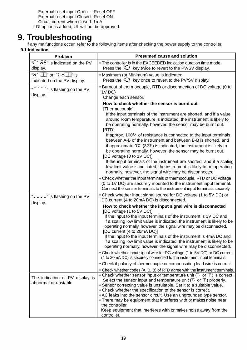
If any malfunctions occur, refer to the following items after checking the power supply to the controller. 9.1 Indication
Problem Presumed cause and solution “ ” is indicated on the PV display.
• The controller is in the EXCEEDED indication duration time mode. Press the key twice to revert to the PV/SV display.
“ ” or“ ” is indicated on the PV display.
• Maximum (or Minimum) value is indicated. Press the key once to revert to the PV/SV display.
“ ” is flashing on the PV display.
• Burnout of thermocouple, RTD or disconnection of DC voltage (0 to 1V DC)
Change each sensor. How to check whether the sensor is burnt out [Thermocouple]
If the input terminals of the instrument are shorted, and if a value around room temperature is indicated, the instrument is likely to be operating normally, however, the sensor may be burnt out.
[RTD] If approx. 100 of resistance is connected to the input terminals between A-B of the instrument and between B-B is shorted, and if approximate 0 (32 ) is indicated, the instrument is likely to be operating normally, however, the sensor may be burnt out.
[DC voltage (0 to 1V DC)] If the input terminals of the instrument are shorted, and if a scalinglow limit value is indicated, the instrument is likely to be operatingnormally, however, the signal wire may be disconnected.
• Check whether the input terminals of thermocouple, RTD or DC voltage (0 to 1V DC) are securely mounted to the instrument input terminal.
Connect the sensor terminals to the instrument input terminals securely.
“ ” is flashing on the PV display.
• Check whether input signal source for DC voltage (1 to 5V DC) or DC current (4 to 20mA DC) is disconnected.
How to check whether the input signal wire is disconnected [DC voltage (1 to 5V DC)] If the input to the input terminals of the instrument is 1V DC and if a scaling low limit value is indicated, the instrument is likely to beoperating normally, however, the signal wire may be disconnected.
[DC current (4 to 20mA DC)] If the input to the input terminals of the instrument is 4mA DC and if a scaling low limit value is indicated, the instrument is likely to beoperating normally, however, the signal wire may be disconnected.
• Check whether input signal wire for DC voltage (1 to 5V DC) or DC current (4 to 20mA DC) is securely connected to the instrument input terminals. • Check if polarity of thermocouple or compensating lead wire is correct.• Check whether codes (A, B, B) of RTD agree with the instrument terminals.
The indication of PV display is abnormal or unstable.
• Check whether sensor input or temperature unit ( or ) is correct.Select the sensor input and temperature unit ( or ) properly.
• Sensor correcting value is unsuitable. Set it to a suitable value. • Check whether the specification of the sensor is correct. • AC leaks into the sensor circuit. Use an ungrounded type sensor. • There may be equipment that interferes with or makes noise near the controller. Keep equipment that interferes with or makes noise away from the controller.
20
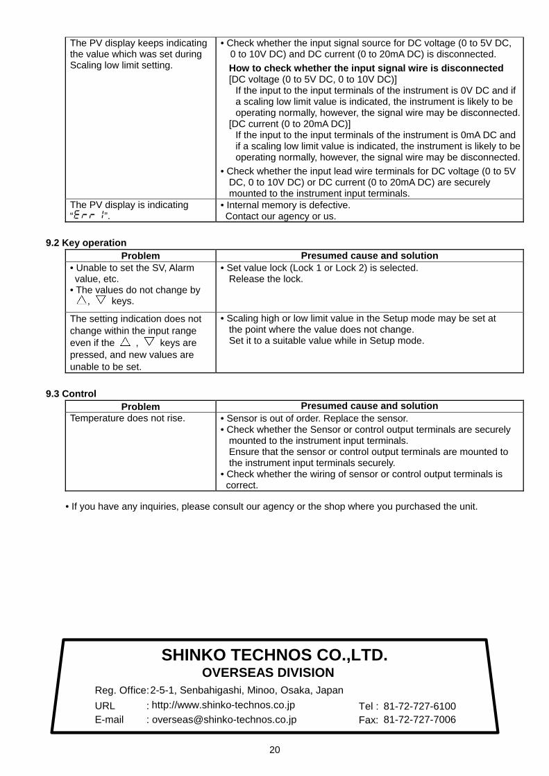
The PV display keeps indicating the value which was set during Scaling low limit setting.
• Check whether the input signal source for DC voltage (0 to 5V DC, 0 to 10V DC) and DC current (0 to 20mA DC) is disconnected. How to check whether the input signal wire is disconnected [DC voltage (0 to 5V DC, 0 to 10V DC)]
If the input to the input terminals of the instrument is 0V DC and ifa scaling low limit value is indicated, the instrument is likely to be operating normally, however, the signal wire may be disconnected.
[DC current (0 to 20mA DC)] If the input to the input terminals of the instrument is 0mA DC andif a scaling low limit value is indicated, the instrument is likely to beoperating normally, however, the signal wire may be disconnected.
• Check whether the input lead wire terminals for DC voltage (0 to 5VDC, 0 to 10V DC) or DC current (0 to 20mA DC) are securely mounted to the instrument input terminals.
The PV display is indicating “ ”.
• Internal memory is defective. Contact our agency or us.
9.2 Key operation
Problem Presumed cause and solution • Unable to set the SV, Alarm value, etc. • The values do not change by
, keys.
• Set value lock (Lock 1 or Lock 2) is selected. Release the lock.
The setting indication does not change within the input range even if the , keys are pressed, and new values are unable to be set.
• Scaling high or low limit value in the Setup mode may be set at the point where the value does not change. Set it to a suitable value while in Setup mode.
9.3 Control
Problem Presumed cause and solution Temperature does not rise. • Sensor is out of order. Replace the sensor.
• Check whether the Sensor or control output terminals are securely mounted to the instrument input terminals. Ensure that the sensor or control output terminals are mounted to the instrument input terminals securely.
• Check whether the wiring of sensor or control output terminals is correct.
• If you have any inquiries, please consult our agency or the shop where you purchased the unit.
SHINKO TECHNOS CO.,LTD.OVERSEAS DIVISION
:::
Reg. OfficeURLE-mail
2-5-1, Senbahigashi, Minoo, Osaka, Japanhttp://[email protected]
Tel :Fax:
81-72-727-610081-72-727-7006