Embed Size (px)
DESCRIPTION
extended surfaces
Citation preview
Extended Surfaces
Chapter Three
Section 3.6
Nature and Rationale
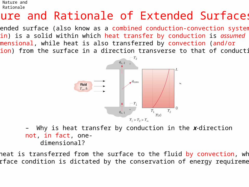
Nature and Rationale of Extended Surfaces• An extended surface (also know as a combined conduction-convection system or a fin) is a solid within which heat transfer by conduction is assumed to be one dimensional, while heat is also transferred by convection (and/or radiation) from the surface in a direction transverse to that of conduction.
– Why is heat transfer by conduction in the x-direction not, in fact, one- dimensional?
– If heat is transferred from the surface to the fluid by convection, what surface condition is dictated by the conservation of energy requirement?
Nature and Rationale (Cont.)
– What is the actual functional dependence of the temperature distribution in the solid?
– If the temperature distribution is assumed to be one-dimensional, that is, T=T(x) , how should the value of T be interpreted for any x location?
– How does vary with x ?,cond xq
– When may the assumption of one-dimensional conduction be viewed as an excellent approximation? The thin-fin approximation.
• Extended surfaces may exist in many situations but are commonly used as fins to enhance heat transfer by increasing the surface area available for convection (and/or radiation). They are particularly beneficial when is small,
as for a gas and natural convection.h
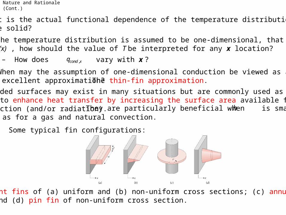
• Some typical fin configurations:
Straight fins of (a) uniform and (b) non-uniform cross sections; (c) annularfin, and (d) pin fin of non-uniform cross section.
Fin Equation
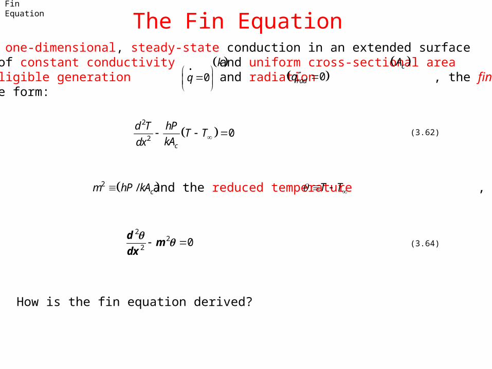
The Fin Equation• Assuming one-dimensional, steady-state conduction in an extended surface surface of constant conductivity and uniform cross-sectional area , with negligible generation and radiation , the fin equation is of the form:
k cA
0q
• 0radq
2
20
c
d T hPT T
kAdx (3.62)
or, with and the reduced temperature , 2 / cm hP kA T T
22
20
dm
dx (3.64)
How is the fin equation derived?
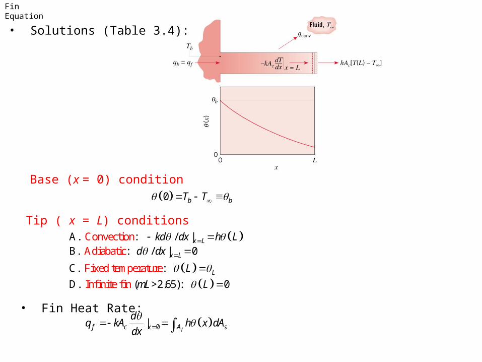
Fin Equation
• Solutions (Table 3.4):
Base (x = 0) condition
0 b bT T
Tip ( x = L) conditions A. : Conve ti |c on / x Lkd dx h L
B. : A / |diabati 0c x Ld dx
Fixed temperC. : ature LL
D. (I >2.65): 0nfinite fin mL L
• Fin Heat Rate: 0|
ff c x A s
dq kA h x dA
dx
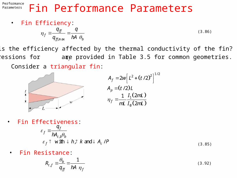
Performance Parameters Fin Performance Parameters• Fin Efficiency:
,max
f ff
f f b
q q
q hA
(3.86)
How is the efficiency affected by the thermal conductivity of the fin?
Expressions for are provided in Table 3.5 for common geometries.f
1/ 2222 / 2fA w L t
/ 2pA t L
1
0
21
2f
I mL
mL I mL
• Fin Effectiveness:
Consider a triangular fin:
,
ff
c b b
q
hA
• Fin Resistance:
with , and /f ch k A P (3.85)
,
1bt f
f f f
Rq hA
(3.92)

Arrays
Fin Arrays• Representative arrays of (a) rectangular and (b) annular fins.
– Total surface area:t f bA NA A (3.99)
Number of fins Area of exposed base (prime surface)
– Total heat rate:
,
bt f f b b b o t b
t o
q N hA hA hAR
(3.101)
– Overall surface efficiency and resistance:
,
1bt o
t o t
Rq hA
(3.103)
1 1fo f
t
NA
A (3.102)
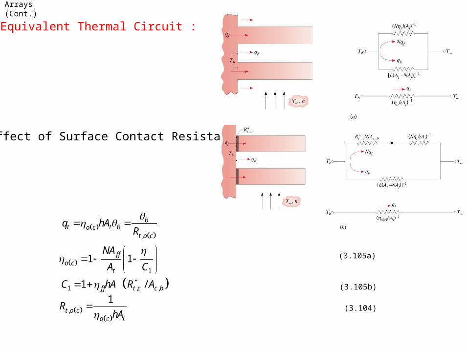
Arrays (Cont.)
• Equivalent Thermal Circuit :
• Effect of Surface Contact Resistance:
,
bt t bo c
t o c
q hAR
1
1 1f fo c
t
NA
A C
(3.105a)
1 , ,1 /f f t c c bC hA R A (3.105b)
,
1t o c
to c
RhA
(3.104)
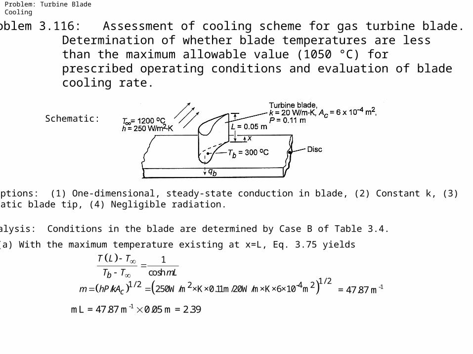
Problem: Turbine Blade Cooling
Problem 3.116: Assessment of cooling scheme for gas turbine blade.Determination of whether blade temperatures are lessthan the maximum allowable value (1050 °C) for prescribed operating conditions and evaluation of bladecooling rate.
Assumptions: (1) One-dimensional, steady-state conduction in blade, (2) Constant k, (3)Adiabatic blade tip, (4) Negligible radiation.
Analysis: Conditions in the blade are determined by Case B of Table 3.4.
(a) With the maximum temperature existing at x=L, Eq. 3.75 yields
Schematic:
1
coshb
T L T
T T mL
1/ 21/ 2 2 -4 2/ 250W/m ×K×0.11m/20W/m×K×6×10 mcm hP kA = 47.87 m-1
mL = 47.87 m-1 0.05 m = 2.39
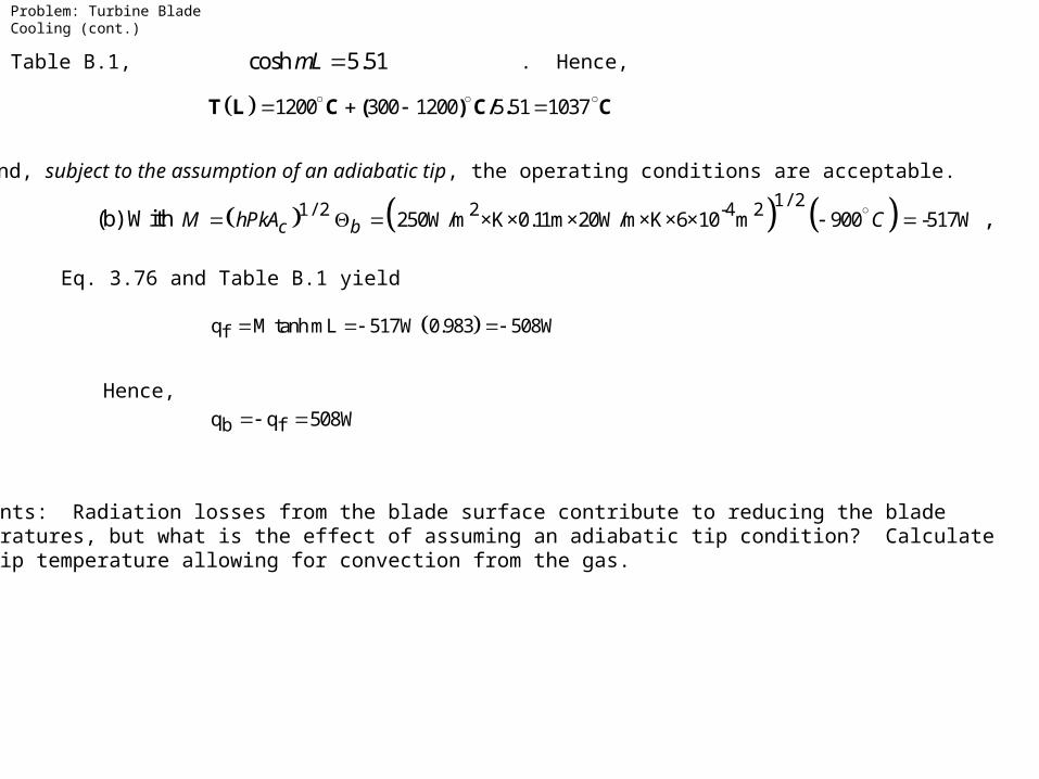
From Table B.1, . Hence,cosh 5.51mL
and, subject to the assumption of an adiabatic tip, the operating conditions are acceptable.
Eq. 3.76 and Table B.1 yield
Hence,
Comments: Radiation losses from the blade surface contribute to reducing the blade temperatures, but what is the effect of assuming an adiabatic tip condition? Calculatethe tip temperature allowing for convection from the gas.
1200 300 1200 5 51 1037 T L C ( ) C/ . C
(b) With 1 / 22 -4 21 / 2 250W/m ×K×0.11m×20W/m×K×6×10 m 900 -517Wc bM hPkA C ,
fq M tanh mL 517W 0.983 508W
b fq q 508W
Problem: Turbine Blade Cooling (cont.)
Problem: Chip Heat Sink
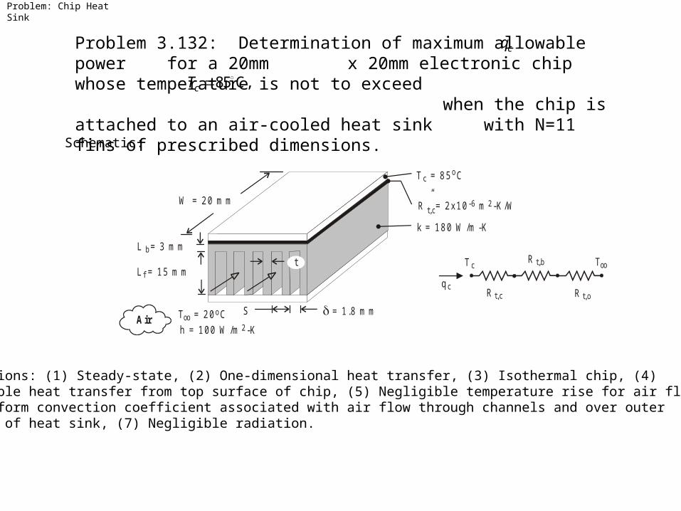
Problem 3.132: Determination of maximum allowable power for a 20mm x 20mm electronic chip whose temperature is not to exceed
when the chip is attached to an air-cooled heat sink with N=11 fins of prescribed dimensions.
cq
85 C,cT
T = 20 C oooAir
k = 180 W /m -K
T = 85 Cco
t,cR” = 2x10 m -K /W-6 2
h = 100 W /m -K 2
L = 15 m m f
L = 3 m m b
W = 20 m m
S = 1.8 m m
t T c
q cR t,c
R t,b
R t,o
T oo
Schematic:
Assumptions: (1) Steady-state, (2) One-dimensional heat transfer, (3) Isothermal chip, (4)Negligible heat transfer from top surface of chip, (5) Negligible temperature rise for air flow,(6) Uniform convection coefficient associated with air flow through channels and over outersurface of heat sink, (7) Negligible radiation.
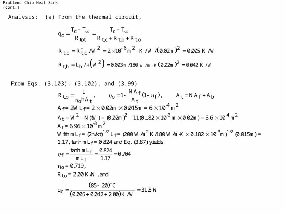
Analysis: (a) From the thermal circuit,
c cc
tot t,c t,b t,o
T T T Tq
R R R R
2 6 2 2t,c t,cR R / W 2 10 m K / W / 0.02m 0.005 K / W
2t,b bR L / k W W / m K
20.003m /180 0.02m 0.042 K / W
From Eqs. (3.103), (3.102), and (3.99)
ft,o o f t f b
o t t
N A1R , 1 1 , A N A A
h A A
Af = 2WLf = 2 0.02m 0.015m = 6 10-4 m2
Ab = W2 – N(tW) = (0.02m)2 – 11(0.182 10-3 m 0.02m) = 3.6 10-4 m2
With mLf = (2h/kt)1/2 Lf = (200 W/m2K/180 W/mK 0.182 10-3m)1/2 (0.015m) =
1.17, tanh mLf = 0.824 and Eq. (3.87) yields
ff
f
tanh mL 0.8240.704
mL 1.17
At = 6.96 10-3 m2
o = 0.719, Rt,o = 2.00 K/W, and
c
85 20 Cq 31.8 W
0.005 0.042 2.00 K / W
Problem: Chip Heat Sink (cont.)
Comments: The heat sink significantly increases the allowable heat dissipation. If it were not used and heat was simply transferred by convection from the surface of the chip with from Part (a) would be replaced by 2
tot100 W/m gK,R =2.05 K/Wh 21/ hW 25 K/W, yielding 2.60 W.cnv cR q
Problem: Chip Heat Sink (cont.)


![IEEE TRANSACTIONS ON VISUALIZATION AND COMPUTER …bjobard.perso.univ-pau.fr/Research/Publications/... · Cohen [6] extended LIC to curvilinear surfaces with animation techniques](https://img.pdfslide.us/doc/110x75/5f0547aa7e708231d4122dd1/ieee-transactions-on-visualization-and-computer-cohen-6-extended-lic-to-curvilinear.jpg)