Embed Size (px)
Citation preview
1
Frequency Selective Surfaces for ExtendedBandwidth Backing Reflector Functions
M. Pasian, Student, IEEE, M. Ettorre, A. Neto, Member, IEEE, S. Monni, Member, IEEE, G. Gerini, SeniorMember, IEEE,
Abstract— This paper deals with the use of Frequency SelectiveSurfaces (FSS) to increase the Efficiency × Bandwidth productin Ultra-Wide Band (UWB) antenna arrays, whose efficiency islimited by the front-to-back ratio. If the backing reflector for theantenna is realized in one metal plane solution, its location willbe suitable only on a relatively limited frequency range especiallyif wide angle scanning is required. In order to extend thefrequency range of usability, an FSS can be sandwiched betweenthe antenna and the ground plane, providing an additionalreflecting plane for an higher frequency band. The possibilityto integrate in the antenna different functionalities, otherwiseperformed by several antennas, is also discussed in the paper.The proposed backing structure composed by the FSS and theground plane has been designed to be used in conjunction withan UWB antenna consisting of an array of connected dipoles. Ahardware demonstrator of the backing structure has also beenmanufactured and tested.
Index Terms— wide-band antenna, wide-scan antenna, fre-quency selective surface, connected array, Green’s function.
I. INTRODUCTION
CURRENT trends in the design of military ship mastsforesee the integration of several functionalities on the
same antenna aperture in order to satisfy the demand ofan increasing number of services to be installed on band,while still responding to the requirement of reducing theRadar Cross-Section (RCS) of the ship itself. In view of this,broadband planar or quasi-planar antennas with large scanningcapabilities are required.
Existing solutions, such as the Vivaldi antenna [1] showgood performances at the cost of low cross polarization purity,which is not acceptable in many cases. Other antennas, such asthe connected array without a backing reflector, as describedin [2], show excellent performances but an efficiency that canbe as low as 50%, because of the poor front-to-back ratio. Toovercome that problem, a backing reflector should be placedat a distance of a fourth of the wavelength, at the center ofthe operating band of the antenna, to achieve coherent sum ofthe radiated and reflected waves at the antenna plane, as donein [3]. However, since the functioning of the back reflector isoptimal in a relatively limited frequency band, the front-to-back ratio comes at the expense of the antenna bandwidth. Inthis sense, it introduces a limitation in the design of broadbandantennas.
M. Pasian is with the University of Pavia, via Ferrata 1, Pavia, Italy. E-mail:[email protected]
M. Ettorre, A. Neto, S. Monni, G. Gerini are with TNO Defence, Safetyand Security, Den Haag 2597 AK, The Netherlands. E-mail: mauro.ettorre,andrea.neto, stefania.monni, [email protected].
Recently, resistive FSSs [4] and Electronic BandGap struc-tures (EBGs) [5] have been proposed to enlarge the operatingbandwidth that would be obtained with conventional groundplanes. In [5], EBGs were designed to extend the bandwidthof operation of an UWB connected array which, however,in the lower frequency range was backed by an absorbinglayer. This choice was dictated by the fact that otherwise abacking metallic reflector, specifically placed to reflect thelowest frequency range, should have been located at a distancefrom the antenna plane in the order of half a meter.
In this paper, the step to achieve good front to back ratios fora wide-angle scanning array antennas without resistive loadingis attempted. A schematic design of a connected dipole array istaken as starting point ( [6], [7]). The considered applicationforesees the integration of two frequency bands, one corre-sponding to the typical radar X-band, 8.50 − 10.50 GHz,and other one corresponding to a Tactical Common DataLink (TCDL) system, 14.40− 15.35 GHz. They both requirescanning capabilities up to ± 45◦. A connected dipole array isbacked by a combination of a ground plane and FSS, whichare designed to behave as perfect reflectors in two differentfrequency ranges. In particular, for lower frequencies, wherethe FSS is transparent for the impinging field, the backingreflector of the array is the real ground plane, whereas in theupper frequency range the FSS behaves as perfect reflector.A prototype of the backing structure consisting of the groundplane and the FSS has been manufactured. The magnitude ofthe reflection coefficient of the FSS alone and the phase of thereflection coefficient of the entire backing structure have beenmeasured.
The Green’s function and the active impedance of thestructure composed by the antenna and the combined backingreflector have also been derived by extending the steps outlinedin [8]. In the transmission line model of the entire structure,the FSS has been described by an equivalent network based ona modal representation in terms of spacial Floquet modes. Theeventual Green’s function provides a physical insights in theproblem and speeds up the antenna design and the optimizationof the relative distance between the antenna, the FSS and theground plane.
The paper is organized as follows. In Sec. II a connecteddipole array backed by a conventional metallic ground plane ispresented. This configuration appears not suitable to integratethe radar and TCDL bands. The solution proposed for thebacking reflector, consisting of the FSS and the ground planeis presented in Sec. III. The measurements of a hardwaredemonstrator of the backing structure are shown in Sec. IV.

2
TABLE IGEOMETRICAL DIMENSIONS IN mm OF THE CONNECTED DIPOLE ARRAY
BACKED BY A SINGLE METAL PLATE, DEPICTED IN FIG. 1
wd t dds dx dy h1
1.5 0.5 3.1 8.3 8.3 8.3
The mathematical details to derive the active impedance ofthe complete antenna and the simulated results for the finalstructure are presented in Sec. V and Sec. VI, respectively.
II. CONNECTED DIPOLE ARRAY ANTENNA WITH BACKINGGROUND PLANE
The ultra-wide band antenna considered in this paper, aconnected dipole antenna, and its complementary counterpart,the long-slot array antenna, have been extensively studied in[2], [3], [8] and [6], [7]. The antenna considered in this paperis shown in Fig. 1, with the parameters defined in Tab. I.
Such an antenna is composed by connected dipoles of widthwd, which are depicted in Fig. 1 as gray strips along the xaxis. The connected dipoles are excited by couples of δ- gapports of width t and relative separation dds, depicted in Fig. 1as thin black lines along the y axis. The dimensions of theunitary cell are dx = dy = 0.415 λmax, where λmax is thefree space wavelength at f = 15 GHz.
The distance h1 between the antenna and the ground planehas been optimized at the value 8.3 mm, trying to cover theentire 8.5 − 15.35 GHz band, for the complete scan range± 45◦. Fig. 2 shows the simulation results for the activereflection coefficient [9], [10], for different scan angles inthe H-plane (y − z plane) obtained with the commercial toolAnsoft HFSS [11]. Taking −10 dB as threshold limit for theactive reflection coefficient, it is evident from Fig. 2 that theground plane solution fulfils the desired requirements only inthe radar frequency band, presenting very poor performancesin the TCDL band.
x
yh1
wd
t
dds
z
dy
dx
Fig. 1. 3-D view of the antenna structure with ground plane.
III. FREQUENCY SELECTIVE SURFACE DESIGN
The previous section clearly showed that the connectedarray with a conventional metal ground plane is not suitableto simultaneously cover the radar and the TCDL bands. Asanticipated in the introduction of this paper, this limitation
-45
-40
-35
-30
-25
-20
-15
-10
-5
0
7 8 9 10 11 12 13 14 15 16
Fig. 2. Magnitude of the active reflection coefficient of the connected dipolearray antenna with the ground plane. Grey strips indicate operative bands
can be overcome by sandwiching an FSS between the arrayand the metal ground plane.
In particular, in this case, the FSS should separate thefrequency bands allocated for naval radar operation, 8.50 −10.50 GHz and for the TCDL, 14.40 − 15.35 GHz, thusproviding a reflection plane for the higher frequency rangeand being practically transparent for the lower band, wherethe metallic ground plane is in charge of the reflection. Ontop of that, both applications ask for a wide-scan capability,up to ± 45◦ in elevation.
In order to achieve the desired behavior the FSS has toexhibit a low-pass response. For this purpose, a commonapproach is to print metallic patches, resonating at the higherfrequency band, on a dielectric substrate. The adopted solutionis based on single-layer structures with a foam substrate, whichis assumed to be electrically equivalent to air. This choiceminimizes the manufacturing effort and the losses. The severeconstraints imposed by the wide angle scanning and steep roll-off required to properly separate the two bands dominated thedesign.
The element shape selected for the FSS is the four-leggeddipole. This kind of element exhibits a good performanceagainst angular variation and, since the total element lengthcan be kept quite small [12], it allows a very packed lattice,with a further gain in angular independence. On the other hand,the more packed the elements are the less steep the roll-off is,due to the capacitive coupling between the elements. For thisreason a proper tradeoff had to be performed.
The chosen final FSS element is depicted in the inset ofFig. 3 and its dimensions are given in Tab. II. The latticeperiodicity, dx = dy = 8.3 mm, equal to that of the connectedarray, allows good angular independence, also avoiding gratinglobes in the considered band. The four-legged dipoles arecapacitively loaded to achieve the required roll-off needed toseparate the radar and the TCDL bands, while preserving theFSS resonance frequency.
The magnitude and phase of the FSS reflection coefficient,simulated with the commercial software Ansoft Designer [13]are reported in Fig. 3. Note that the phase of the reflection

3
-18
-16
-14
-12
-10
-8
-6
-4
-2
0
7 8 9 10 11 12 13 14 15 16-200
200
y
Fig. 3. Magnitude and phase of the reflection coefficient of the FSS fordifferent scan angles in the y−z plane for a x-polarized plane wave incidence.
-200
-150
-100
-50
0
50
100
150
200
7 8 9 10 11 12 13 14 15 16
Fig. 4. Phase of the reflection coefficient of the FSS backed by a groundplane for different scan angles in the y−z plane for a x-polarized plane waveincidence.
coefficient is evaluated at the FSS plane itself. A uniformplane wave polarized along the x-axis, impinging at differentincidence angles along the y − z plane, was considered asexcitation. It can be observed that the FSS does not exactlyresonate at the center of the TCDL band. Because of theproximity and thus the interaction between the FSS itself andthe ground plane, the FSS design had to be tuned to optimizethe phase behavior of the complete backing reflector (FSS +ground plane).
Then, the optimal distances between the ground plane andthe FSS, and between the FSS itself and the antenna planehad to be determined. In first approximation the FSS and theground plane should be placed at a distance of λ/4 fromthe antenna plane, calculated at central frequencies of thetwo considered frequency bands. In this way, a constructiveinterference between the direct field generated by the antenna
TABLE IIGEOMETRICAL DIMENSIONS IN mm OF THE BACKING PLANE COMPOSED
BY THE FSS AND THE GROUND PLANE DEPICTED IN FIG. 3 AND FIG. 4
w l b d d20.2 2.245 0.6 0.7 1.2
and the one coming back from the FSS or ground plane wouldbe obtained.
On the other hand, the interaction between the ground planeand the FSS, which are very close to each other in terms ofwavelength, has a significant impact on the final results. Forthis reason a fast full-wave method was used to accuratelycalculate the best distances, as described in Sect. V. Theobtained values, h1 and h2, (see Fig. 9) are reported in Tab. III
Fig. 4 reports the phase of the reflection coefficient exhibitedby the entire structure composed by the FSS and the groundplane, for scanning angles up to 45◦. The phase responsedepicted in Fig. 4 is evaluated at the optimized distance h1
of 6.5 mm between FSS and antenna plane. The magnitudeof the reflection coefficient is not reported because it is alwaysequal to 0 dB, due to the presence of the perfectly metallicground plane.
It can be observed that the constructive interference, whichis indicated by a reflected phase equal to 0◦, is roughlyachieved at the centers of the two separate operating bands.
Thanks to the symmetry of the FSS structure, an orthog-onal polarization would present the same behavior, allowingtherefore the use of this kind of element shape for circularlypolarized antennas.
IV. MEASUREMENTS
The backing plane design was carried out considering onlyfoam as substrate, but manufacturing constraints required theuse of an extra dielectric support, as depicted in the insetof Fig. 8. The original design was tuned to account for thedifferent equivalent dielectric constant. The FSS was printedon a 60 × 60 cm thin dielectric substrate from Rogers, LG4002(εr1 = 2.89, t1 = 0.075 mm). This layer was glued on afoam from Rohacell (εr3 = 1.06, t3 = 2.2 mm) by meansof an adhesive film from Arlon, CuClad 6250 (εr2 = 2.32,t2 = 0.039 mm). A metallic plate was then fixed at the bottomof the foam, finalizing the manufacturing of the completebacking structure. A close-up photograph of the FSS withoutthe metallic plate is shown in Fig. 5
Two measurement setups were considered: one for the FSSalone, before attaching the ground plane, and the other one forthe complete backing structure. Both measurements took placein an anechoic chamber using two standard wide-band double-ridge horn antennas, in a quasi-monostatic configuration forbroadside measurements and in a bistatic configuration forother angles of incidence.
The position of the backing plane and of the FSS werecontrolled thanks to a mechanical construction consisting ofa mast, two vertical and horizonal poles, with elevation andazimuth adjustable joints, and a square frame (Fig. 6). Themast was specifically designed for microwave measurementsshowing a reflection coefficient better than −30 dB. The mainpart of the entire support consisted of a square frame wherethe backing plane could be precisely slid in. This frame wasconnected to the rest of the support by means of two verticaland two horizontal arms bent behind the frame, to reduce theircontribution to the reflection. Thanks to this arrangement mostof the reflection was caused by parts located at about 30 cm

4
away from the frame. Therefore, such reflection contributionscould be removed from the measurement by applying a propertime gating in the network analyzer. Absorbing material wasplaced around the frame to reduce edge effects and to hide thesupporting structure mentioned before. The alignment betweenthe backing plane and the horn antennas was controlled bymeans of laser beams and optimized by adjusting the elevationand azimuth joints.
Fig. 5. Close-up view of the manufactured FSS.
Fig. 6. Photograph of the mechanical support.
When measuring the reflection phase, any even little in-accuracy may translate in several degrees of errors. For thisreason, a particular measurement procedure was applied toretrieve the phase of the reflection coefficient of the backingplane under test, minimizing errors due to edge effects, tothe fact that the electromagnetic field generated by the hornantenna is not a uniform plane wave and due to deviations ofthe horn antenna phase center position with the frequency. Aconventional metallic reflector, with dimension and positionexactly equal to the ones of the backing plane under test, wasused as reference. The phase of the reflection coefficient givenby the perfect metallic plate recorded by the network analyzercan be written as:
α = 2kd− π + E (1)
where α is the phase recorded by the horn antenna, d is the
distance between the horn antenna and the metallic plate, πis the analytical reflection phase given by an infinity perfectlyconducting plate and E takes into account any other error.
Then the backing structure was measured and a similarequation holds:
β = 2kd + γ + E (2)
where β is the phase recorded by the horn antenna and γ isthe reflection phase given by the backing structure. The errorE was assumed to be equal in both cases.
Now it is possible to obtain the requested value γ, substi-tuting (1) into (2):
γ = β − α− π (3)
Of course, after this procedure, it is still necessary to reportthe retrieved reflection phase given by the backing structure tothe plane where the antenna array will be placed, at a distanceof h1 = 6.5 mm as shown in the previous section.
A similar reference procedure was also followed to calibratethe response of the FSS alone. In this case the magnitude ofthe reflection coefficient was obtained considering as referencethe reflection coefficient of the complete backing structure. Infact, the latter has a magnitude of the reflection coefficientequal to 0 dB at any frequency.
The experimental results are shown in Fig. 7 and Fig. 8,where they are compared with the results obtained fromsimulations for incidence angle of 0◦, 30◦ and 45◦. Theagreement between theory and measurement is very good,both for the magnitude and the phase response. In particular,Fig. 7 shows an excellent agreement close to the resonanceregion of the FSS, with some minor differences at lowerfrequencies, where the FSS is almost invisible and thereforethe mechanical structure behind it may have affected themeasure. At the highest frequency range a slight shift can beobserved, which is probably due to some small unpredictablevariations of the features of the dielectric support during themanufacturing process. Fig. 8 shows the phase response ofthe complete backing plane, calculated at the antenna planeas described in the inset of Fig. 8 itself. The agreement isvery good for all considered angles, despite the extremelyhigh accuracy required for such measurement and despite therate of the phase variation in proximity of the FSS resonance.Small discrepancies at lower frequency are probably dueto a differences between the actual and nominal values ofthe dielectric constant and of the thickness of the dielectricsupport. Overall the phase of the composite backing reflectorand the amplitude of the FSS alone are in excellent agreementwith the design. The minor frequency shift in the TCDL bandcould be easily tuned out.
V. 2-D CONNECTED ARRAY: ACTIVE IMPEDANCE IN THEPRESENCE OF THE FSS
The active impedance of connected dipole arrays backedby a ground plane and FSS can be derived extending thesteps outlined in previous works [2] and [8], where theGreen’s function and the active impedance for a 2-D long slotconnected array was found.

5
7 8 9 10 11 12 13 14 15 16-25
-20
-15
-10
-5
0
Fig. 7. Measured magnitude of the reflection coefficient of the FSS. Linesrefer to HFSS results while symbols to measurement
-200
-150
-100
-50
0
50
100
150
200
7 8 9 10 11 12 13 14 15 16
antenna plane
6.5 mm
( , t )er1 1
( , t )er2 2
( , t )er3 3
drawingnot to scale
Fig. 8. Measured phase of the reflection coefficient of the FSS backed by aground plane. Lines refer to HFSS results while symbols to measurement
TABLE IIIGEOMETRICAL DIMENSIONS IN mm OF THE CONNECTED DIPOLE ARRAY
BACKED BY THE FSS AND THE GROUND PLANE, DEPICTED IN FIG. 9
wd t dds dx dy h1 h2
1.5 0.5 3.1 8.3 8.3 6.5 2.3
x
yh1
dy
dx
h2
wd
t
dds
z
Fig. 9. 3-D view of the antenna structure with the FSS and the ground plane.
The complete structure and its equivalent transmission linemodel are shown in Fig. 9 and Fig. 10 respectively. In theequivalent transmission line model, the discontinuity intro-duced by the FSS is described by a N-port network placedin parallel.
Ground Plane
DipolePlane
z
ZFSS
Ig
Zx
44
NNZts
Z 00Z
00pZ44
NNp
ZpstZ
nmZ
nm44
NNts 00
4
N+1
4
N+1
4
N-1- -
4
N-1
4
N-1- -
4
N-1
Z Z4
N+1
4
N+1
Fig. 10. Equivalent transmission line model of the planar structure of Fig. 9.
This network describes the interactions among N modes,TE and TM, of the pertinent Floquet mode expansion. Evenif usually only the fundamental Floquet mode is propagatingin the considered frequency range, due to the proximity of theground plane and of the slot plane the first order modes mayalso introduce some reactive loads. Accordingly an impedancematrix has been used to describe the N -port network of theFSS which has been derived by using a home-made tool basedon the Method of Moments [14].
The final expression for the active impedance of the config-uration shown in Fig. 9 assumes an expression similar to theone reported in [7] for a 2-D long slot connected array withbacking reflector:
zfsin∞ =
dx
dy
1∞∑
mx=−∞
cos2(kkxmdds/2) sinc2(kkxmt/2)∑∞ny=−∞Gxx(kxm, kyn) Jt(kyn)
(4)
where dx and dy are the periodicities of the array, dds is thedistance between two feeds inside each unit cell, Jt is theFourier transform of the transverse distribution of the electriccurrent on the dipoles, Gxx is the pertinent Green’s functionfor the electric field due to electric sources and kxm and kyn
are the (m, n) Floquet mode propagation constants along xand y given by
kxm = k0 sin(θ) cos(φ)− 2πm
dx(5)
kyn = k0 sin(θ) sin(φ)− 2πn
dy(6)
where θ and φ are the usual angles in a spherical referencesystem and k0 is the free-space propagation constant. Pleaserefer to [8] for a more accurate definition of the functions usedin the previous and following expressions.
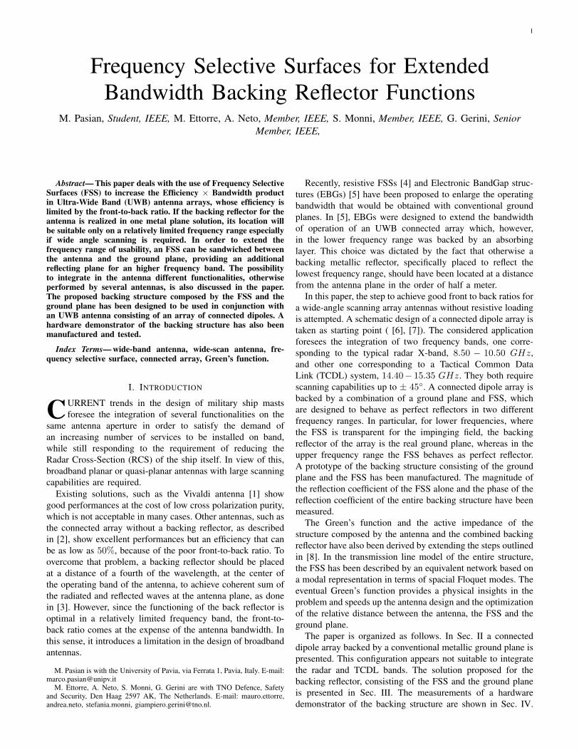
The term Gxx can be obtained by using the equivalenttransmission line model of Fig. 10. In particular, for (4) weare interested in the value assumed by the Green’s function at(kxm,kyn). This value can be found by calculating the voltage
6
Zx
Zpx
Zlin
h1 Zmn
Ig
Zmn
Zd
mn
Fig. 11. Transmission line used to find the voltage at the connected dipolearray level for the (m, n) Floquet mode.
VTE/TM , for the two polarizations TE and TM , at the dipolelevel in the (m, n) mode transmission line, see Fig. 11, when aunitary current generator is feeding this line. In mathematicalterms, Gxx is given by
Gxx(kxm, kyn) =−1
k2xm + k2
yn
(VTM k2xm + VTE k2
yn) (7)
Note that the unit current generator represents the currentsin the connected array, at z = h1 + h2. Moreover, note thatall the lines looking into the ground plane are representedvia short circuits at z = 0. Also, all the lines looking fromz = h2 upward, except the one for m = n, are closed inmatching loads. The higher order modes are attenuated anddo not significantly contribute to the interaction between theground plane, the antenna and the FSS.
Eventually it is possible to solve the transmission lineproblem defined by (7) for each mode (m,n) in (4) to obtainseparate active equivalent networks as in Fig. 11 where thecoupling of the other modes (ports in Fig. 10) is alreadyaccounted for.
The advantage of this representation is that once the equiv-alent transmission line of the FSS is obtained, the only twoparameters remaining to the designer, h1 and h2, can be opti-mized very efficiently. The Green’s function now represents afast and accurate tool that also includes the effects due to theFSS.
Once the GF (4) is known, it is possible to study thefinal antenna structure shown in Fig. 9, where the FSS is theone designed in Sec. III. The dimensions of the structure arereported in Tab. III.
VI. ARRAY PERFORMANCES
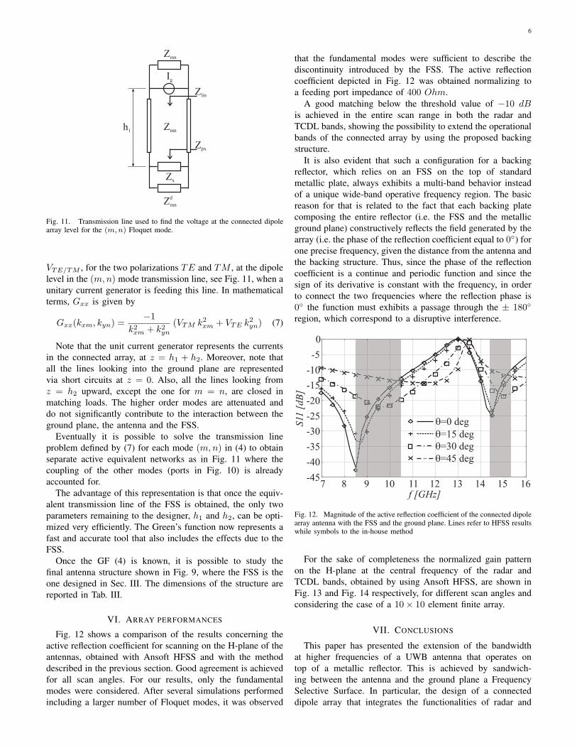
Fig. 12 shows a comparison of the results concerning theactive reflection coefficient for scanning on the H-plane of theantennas, obtained with Ansoft HFSS and with the methoddescribed in the previous section. Good agreement is achievedfor all scan angles. For our results, only the fundamentalmodes were considered. After several simulations performedincluding a larger number of Floquet modes, it was observed
that the fundamental modes were sufficient to describe thediscontinuity introduced by the FSS. The active reflectioncoefficient depicted in Fig. 12 was obtained normalizing toa feeding port impedance of 400 Ohm.
A good matching below the threshold value of −10 dBis achieved in the entire scan range in both the radar andTCDL bands, showing the possibility to extend the operationalbands of the connected array by using the proposed backingstructure.
It is also evident that such a configuration for a backingreflector, which relies on an FSS on the top of standardmetallic plate, always exhibits a multi-band behavior insteadof a unique wide-band operative frequency region. The basicreason for that is related to the fact that each backing platecomposing the entire reflector (i.e. the FSS and the metallicground plane) constructively reflects the field generated by thearray (i.e. the phase of the reflection coefficient equal to 0◦) forone precise frequency, given the distance from the antenna andthe backing structure. Thus, since the phase of the reflectioncoefficient is a continue and periodic function and since thesign of its derivative is constant with the frequency, in orderto connect the two frequencies where the reflection phase is0◦ the function must exhibits a passage through the ± 180◦
region, which correspond to a disruptive interference.
-45
-40
-35
-30
-25
-20
-15
-10
-5
0
7 8 9 10 11 12 13 14 15 16
Fig. 12. Magnitude of the active reflection coefficient of the connected dipolearray antenna with the FSS and the ground plane. Lines refer to HFSS resultswhile symbols to the in-house method
For the sake of completeness the normalized gain patternon the H-plane at the central frequency of the radar andTCDL bands, obtained by using Ansoft HFSS, are shown inFig. 13 and Fig. 14 respectively, for different scan angles andconsidering the case of a 10× 10 element finite array.
VII. CONCLUSIONS
This paper has presented the extension of the bandwidthat higher frequencies of a UWB antenna that operates ontop of a metallic reflector. This is achieved by sandwich-ing between the antenna and the ground plane a FrequencySelective Surface. In particular, the design of a connecteddipole array that integrates the functionalities of radar and

7
-30
-25
-20
-15
-10
-5
0
-100 -80 -60 -40 -20 0 20 40 60 80 100
Fig. 13. Radiation patterns on the H-Plane for different scan angles at thecentral frequency of the radar band, f = 9.5 GHz, for the connected dipolearray antenna backed by the ground plane and FSS. The pattern are normalizedto the maximum value for broadside radiation.
-30
-25
-20
-15
-10
-5
0
-100 -80 -60 -40 -20 0 20 40 60 80 100
Fig. 14. Radiation patterns on the H-Plane for different scan angles at thecentral frequency of the TCDL band, f = 15 GHz, for the connected dipolearray antenna backed by the ground plane and FSS. The pattern are normalizedto the maximum value for broadside radiation.
the Tactical Common Data Link (TCDL) applications, hasbeen presented. A prototype of the backing reflector madeby the FSS and the ground plane has been manufactured andsuccessfully tested, showing very good agreement betweenpredictions and measurement. Besides, the procedure to derivethe active impedance for the complete antenna structure hasbeen illustrated. The results have been compared with theones obtained through commercial tools showing an excellentagreement.
It may be noted that the performance achievable from theconnected dipole array backed by the composite reflectorare significantly dependent from the scan angle. Thus, thedistances between the reflecting planes and the antenna h1 andh2, should always be accurately tuned for optimal performanceof the full angular range. To this purpose, the availability ofthe active Green’s function presented in Sec. V dramaticallyaccelerates the design optimization.
ACKNOWLEDGMENT
This work has been supported by TNO and by NL Ministryof Defense in the frame of the research program IntegratedTechnology Mast Systems. The authors wish to thank FransNennie, Peter Kuivenhoven and Michiel Bruijn for their crucialcontributions to the fabrication of the mechanic support andto the measurement campaign.
REFERENCES
[1] J. J. Lee, S. Livingston, and R. Koenig, “A Low-Profile Wide-Band (5:1)Dual-Pol Array”, IEEE Antennas and Wireless Propagation Letters, Vol.2,pp. 46-49, Dec. 2003.
[2] A. Neto and J. J. Lee, “Infinite bandwidth long slot array antenna”, IEEEAntennas and Wireless Propagation Letters, Vol.3, pp. 75-78, Dec. 2005.
[3] J. J. Lee, S. Livingston, R. Koenig, D. Nagata and L. L. Lai, “CompactLight Weight UHF Arrays Using Long Slot Apertures”, IEEE Transac-tions on Antennas and Propagation, Vol.54, no.7, pp. 2009-2015, Jul.2006.
[4] Y. E. Erdemli, K. Sertel, R. A. Gilbert, D. E. Wright and J. L. Volakis,“Frequency-Selective Surfaces to Enhance Performance of Broad-BandReconfigurable Arrays”, IEEE Transactions on Antennas and Propaga-tion, Vol.50, no.12, pp. 1716-1724, Dec. 2002.
[5] J. M. Bell, M. F. Iskander and J. J. Lee, “Ultrawideband HybridEBG/Ferrite Ground Plane for Low-Profile Array Antennas”, IEEETransactions on Antennas and Propagation, Vol.55, no.1, pp. 4-12, Jan.2007.
[6] D. Cavallo, A. Neto, G. Gerini and G. Toso, “On the Potentials ofConnected Slots and Dipoles in the Presence of a Backing Reflector”,30th ESA Antenna Workshop, Noordwijk, The Netherlands, 27-30 May2008.
[7] A. Neto, D. Cavallo, G. Gerini and G. Toso, “Scanning Performances ofWide Band Connected Arrays in the Presence of a Backing Reflector”,IEEE Transactions on Antennas and Propagation, submitted.
[8] A. Neto and J. J. Lee, “Ultrawide-Band Properties of Long Slot Arrays”,IEEE Transactions on Antennas and Propagation, Vol.54, no.2, pp. 534-543, Feb. 2006.
[9] R. C. Hansen, Phased Array Antennas,USA: John Wiley and Sons, 1998.[10] D. M. Pozar, “The Active Element Pattern”, IEEE Transactions on
Antennas and Propagation, Vol.42, no.8, pp. 1176-1178, Aug. 1994.[11] Ansoft HFSS version 10.0, 1984-2007 Ansoft Corporation.[12] B. A. Munk, Frequency Selective Surfaces: Theory and Design, USA:
John Wiley and Sons, 2000.[13] Ansoft Designer version 3.0.0, 1984-2007 Ansoft Corporation.[14] S. Monni, G. Gerini, A. Neto and A.G. Tijhuis, “Multimode Equivalent
Networks for the Design and Analysis of Frequency Selective Surfaces”,IEEE Transactions on Antennas and Propagation, Vol.55, no.10, Oct.2007.


![[1967] Sewall Wright - Surfaces of Selective Value](https://img.pdfslide.us/doc/110x75/577c805c1a28abe054a8574c/1967-sewall-wright-surfaces-of-selective-value.jpg)