Embed Size (px)
Citation preview

Optimization of Extended Surfaces on Tubes of The Radiant Section of Fired Heaters
Ivan C. Silva1 and Marcelo J. Colaço2
1PETROBRAS – Petróleo Brasileiro S.A. Research Center (CENPES)
Av. Horácio Macedo, 950, 21941-915 Rio de Janeiro, Brazil
Email: [email protected]
2Department of Mechanical Engineering
Federal University of Rio de Janeiro (PEM-COPPE/UFRJ)
Cx. Postal 68503, 21941-972, Rio de Janeiro, Brazil
Email: [email protected]
ABSTRACT
This paper proposes the use of non-uniform extended surfaces installed externally to the tubes of the
radiation section of fired heaters, in order to obtain a better heat flux distribution to the coils. To this end,
the heat transfer mechanisms present in such equipment were studied through computational fluid dynamics
(CFD), using simplified geometries that represent typical sizes of fired heaters. Also, a simplified model
for the combustion was considered. Although this model oversimplifies the physics of the problem, it was
able to give satisfactory results for the parameters being optimized, considering the main objective of this
paper, that is to minimize the non-uniformity of heat flux in the tubes of the radiant section of fired heaters.
It was possible to obtain optimized geometric parameters for different types of extended surfaces evaluated,
coupling the results of these models with the Particle Swarm optimization method using a response surface
technique. The results indicate a significant improvement in the uniformity of the heat flux distribution to
the tubes through the use of the proposed extended surfaces. Thus, this solution reveals to be an interesting
alternative to reduce the risks of fluid degradation and coking formation. Future studies must investigate
the non-uniformity of the heat flux due to the presence of the flame and consider the interaction between
the reactive flow and the participating medium. Nevertheless, this paper presents some results that justify
the optimization of such extended surfaces taking into consideration thermal radiation.
Keywords: optimization; particle swarm; response surface; extended surface; fired heaters;
computational fluid dynamics
1. INTRODUCTION
Fired heaters are combustion equipment present in many process plants where there is a need to provide
thermal energy to a fluid in order to heat it, vaporize it or promote chemical reactions. In refineries they are
major energy consumers, directly impacting the operation costs and profitability.
In these equipment part of the energy released by the combustion is transferred to the fluid circulating
inside the tubes placed in the combustion chamber. Radiation is the main heat transfer mechanism, due to
Preprints (www.preprints.org) | NOT PEER-REVIEWED | Posted: 3 June 2020 doi:10.20944/preprints202006.0010.v1
© 2020 by the author(s). Distributed under a Creative Commons CC BY license.
Optimization of extended surfaces on tubes of the radiant section of fired heaters
the high temperatures achieved and the participation of asymmetric diatomic gases generated in the
combustion, mainly CO2 and H2O.
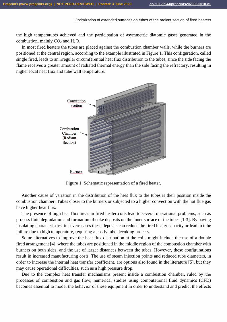
In most fired heaters the tubes are placed against the combustion chamber walls, while the burners are
positioned at the central region, according to the example illustrated in Figure 1. This configuration, called
single fired, leads to an irregular circumferential heat flux distribution to the tubes, since the side facing the
flame receives a greater amount of radiated thermal energy than the side facing the refractory, resulting in
higher local heat flux and tube wall temperature.
Figure 1. Schematic representation of a fired heater.
Another cause of variation in the distribution of the heat flux to the tubes is their position inside the
combustion chamber. Tubes closer to the burners or subjected to a higher convection with the hot flue gas
have higher heat flux.
The presence of high heat flux areas in fired heater coils lead to several operational problems, such as
process fluid degradation and formation of coke deposits on the inner surface of the tubes [1-3]. By having
insulating characteristics, in severe cases these deposits can reduce the fired heater capacity or lead to tube
failure due to high temperature, requiring a costly tube decoking process.
Some alternatives to improve the heat flux distribution at the coils might include the use of a double
fired arrangement [4], where the tubes are positioned in the middle region of the combustion chamber with
burners on both sides, and the use of larger distances between the tubes. However, these configurations
result in increased manufacturing costs. The use of steam injection points and reduced tube diameters, in
order to increase the internal heat transfer coefficient, are options also found in the literature [5], but they
may cause operational difficulties, such as a high pressure drop.
Due to the complex heat transfer mechanisms present inside a combustion chamber, ruled by the
processes of combustion and gas flow, numerical studies using computational fluid dynamics (CFD)
becomes essential to model the behavior of these equipment in order to understand and predict the effects
Preprints (www.preprints.org) | NOT PEER-REVIEWED | Posted: 3 June 2020 doi:10.20944/preprints202006.0010.v1

Optimization of extended surfaces on tubes of the radiant section of fired heaters
of changes in the operating variables. Given the importance of combustion in industry processes, several
studies have been conducted in order to create numerical models capable of describing this phenomenon
[6, 7]. Radiation, the main heat transfer mechanism associated with combustion, has also been the subject
of interest and numerous models have been proposed in order to predict its behavior, especially in the
presence of participating medium [8]. Using these advances in models describing the heat transfer and fluid
flow mechanisms present in combustion systems, many studies have been conducted to evaluate the
performance of real fired heaters using CFD software [9-11]. These evaluations successfully allowed
observing the influence of operating variables on the heat transfer to the coils and the effects of non-uniform
heat flux distribution described above. However, the search for solutions to improve the heat flux
distribution to the fired heaters tubes was not the main focus of these studies.
Since the circumferential heat flux variation is the major effect that increases the ratio between the
maximum and the mean heat flux to the tube coils in single fired heaters [12], a more uniform heat flux
would lead to lower risk of fluid degradation and coke formation, allowing the design of combustion
chambers with higher heat transfer capacity and longer operation times.
Thus, this study proposes the use of non-uniform extended surfaces installed externally to the tubes of
the radiation section of fired heaters, in order to obtain a better heat flux distribution to the coils. For this
purpose, simplified finite volume numerical models were used to represent the heat transfer mechanisms
present in this equipment. In order to obtain the best geometric parameters for two different extended
surfaces profiles (trapezoidal and parabolic), the Particle Swarm optimization method was used together
with a Response Surface technique.
2. PHYSICAL PROBLEM
2.1. Extended surfaces
The extended surfaces proposed in this study are circular type fins with two different profiles: trapezoidal
and parabolic, as illustrated in Figure 2. The thickness of the tip (2wp) and the fin height were kept fixed,
equal to 1.27 mm and 25.4 mm respectively, as recommended limits [13] for the convection section tubes.
A distance between the bases of the fins was also used with a constant value of 5 mm, in order to provide
a suitable space for fixing the fins to the tubes. Thus, an increase in the thickness of the fin base (2wb) leads
to a reduction in the number of fins per tube unit length.
In order to avoid increasing the maximum heat flux in the tubes, the proposed fins do not extend
throughout the circumference of the tubes. In this way, the tube side facing the flame was maintained with
a bare surface, and the fin extension was defined by the variable shown in Figure 3.
Preprints (www.preprints.org) | NOT PEER-REVIEWED | Posted: 3 June 2020 doi:10.20944/preprints202006.0010.v1

Optimization of extended surfaces on tubes of the radiant section of fired heaters
Figure 2. Trapezoidal and parabolic fins (dimensions in mm).
Figure 3. Fin extension angle.
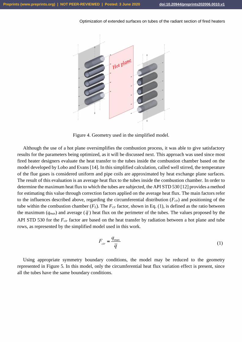
2.2. Simplified model – radiation only
Since radiation is the main heat transfer process to the coils in fired heaters combustion chambers, this
first model considers only this mechanism. The geometry analyzed is illustrated in Figure 4, where a hot
surface, representing the flame, irradiates heat to a tube bank against a wall.
Preprints (www.preprints.org) | NOT PEER-REVIEWED | Posted: 3 June 2020 doi:10.20944/preprints202006.0010.v1
Optimization of extended surfaces on tubes of the radiant section of fired heaters
Figure 4. Geometry used in the simplified model.
Although the use of a hot plane oversimplifies the combustion process, it was able to give satisfactory
results for the parameters being optimized, as it will be discussed next. This approach was used since most
fired heater designers evaluate the heat transfer to the tubes inside the combustion chamber based on the
model developed by Lobo and Evans [14]. In this simplified calculation, called well stirred, the temperature
of the flue gases is considered uniform and pipe coils are approximated by heat exchange plane surfaces.
The result of this evaluation is an average heat flux to the tubes inside the combustion chamber. In order to
determine the maximum heat flux to which the tubes are subjected, the API STD 530 [12] provides a method
for estimating this value through correction factors applied on the average heat flux. The main factors refer
to the influences described above, regarding the circumferential distribution (Fcir) and positioning of the
tube within the combustion chamber (FL). The Fcir factor, shown in Eq. (1), is defined as the ratio between
the maximum (qmax) and average (q ) heat flux on the perimeter of the tubes. The values proposed by the
API STD 530 for the Fcir factor are based on the heat transfer by radiation between a hot plane and tube
rows, as represented by the simplified model used in this work.
(1)
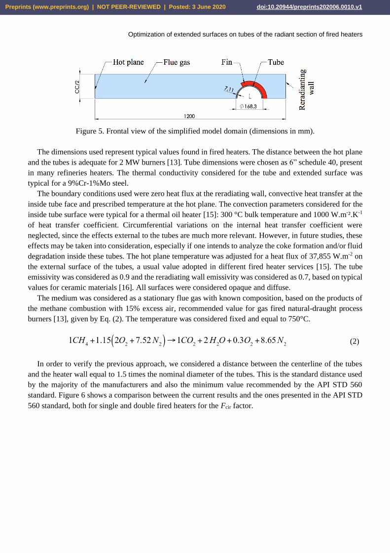
Using appropriate symmetry boundary conditions, the model may be reduced to the geometry
represented in Figure 5. In this model, only the circumferential heat flux variation effect is present, since
all the tubes have the same boundary conditions.
Preprints (www.preprints.org) | NOT PEER-REVIEWED | Posted: 3 June 2020 doi:10.20944/preprints202006.0010.v1
Optimization of extended surfaces on tubes of the radiant section of fired heaters
Figure 5. Frontal view of the simplified model domain (dimensions in mm).
The dimensions used represent typical values found in fired heaters. The distance between the hot plane
and the tubes is adequate for 2 MW burners [13]. Tube dimensions were chosen as 6” schedule 40, present
in many refineries heaters. The thermal conductivity considered for the tube and extended surface was
typical for a 9%Cr-1%Mo steel.
The boundary conditions used were zero heat flux at the reradiating wall, convective heat transfer at the
inside tube face and prescribed temperature at the hot plane. The convection parameters considered for the
inside tube surface were typical for a thermal oil heater [15]: 300 °C bulk temperature and 1000 W.m-².K-1
of heat transfer coefficient. Circumferential variations on the internal heat transfer coefficient were
neglected, since the effects external to the tubes are much more relevant. However, in future studies, these
effects may be taken into consideration, especially if one intends to analyze the coke formation and/or fluid
degradation inside these tubes. The hot plane temperature was adjusted for a heat flux of 37,855 W.m-2 on
the external surface of the tubes, a usual value adopted in different fired heater services [15]. The tube
emissivity was considered as 0.9 and the reradiating wall emissivity was considered as 0.7, based on typical
values for ceramic materials [16]. All surfaces were considered opaque and diffuse.
The medium was considered as a stationary flue gas with known composition, based on the products of
the methane combustion with 15% excess air, recommended value for gas fired natural-draught process
burners [13], given by Eq. (2). The temperature was considered fixed and equal to 750°C.
(2)
In order to verify the previous approach, we considered a distance between the centerline of the tubes
and the heater wall equal to 1.5 times the nominal diameter of the tubes. This is the standard distance used
by the majority of the manufacturers and also the minimum value recommended by the API STD 560
standard. Figure 6 shows a comparison between the current results and the ones presented in the API STD
560 standard, both for single and double fired heaters for the Fcir factor.
Preprints (www.preprints.org) | NOT PEER-REVIEWED | Posted: 3 June 2020 doi:10.20944/preprints202006.0010.v1

Optimization of extended surfaces on tubes of the radiant section of fired heaters
Figure 6. Comparison between current results the API STD 560 for the Fcir factor.
In Fig. 6, De is the external diameter of the tubes and Lcc is the distance between the centerline of two
tubes. Results for the Fcir factor agree very well with the ones reported by the API Standard, which shows
that the proposed geometry, the radiation model and the mesh used are suited to evaluate the effects of
irregular circumferential distribution of radiation to fired heater tubes. Since the objective of this paper is
to optimize such factor, as it will be discussed next, and not analyze the fluid flow process in details, the
authors believe that the employed approximations are valid for this initial study. Nevertheless, future works
shall take into consideration the interaction of the burners and the influence of the inhomogeneous heat flux
along the flame.
2.3. Refined model – radiation and convection
In order to include the effects of convection, as well as to add different boundary conditions for the tubes,
representing the positioning effects within the combustion chamber, a more elaborate model is proposed.
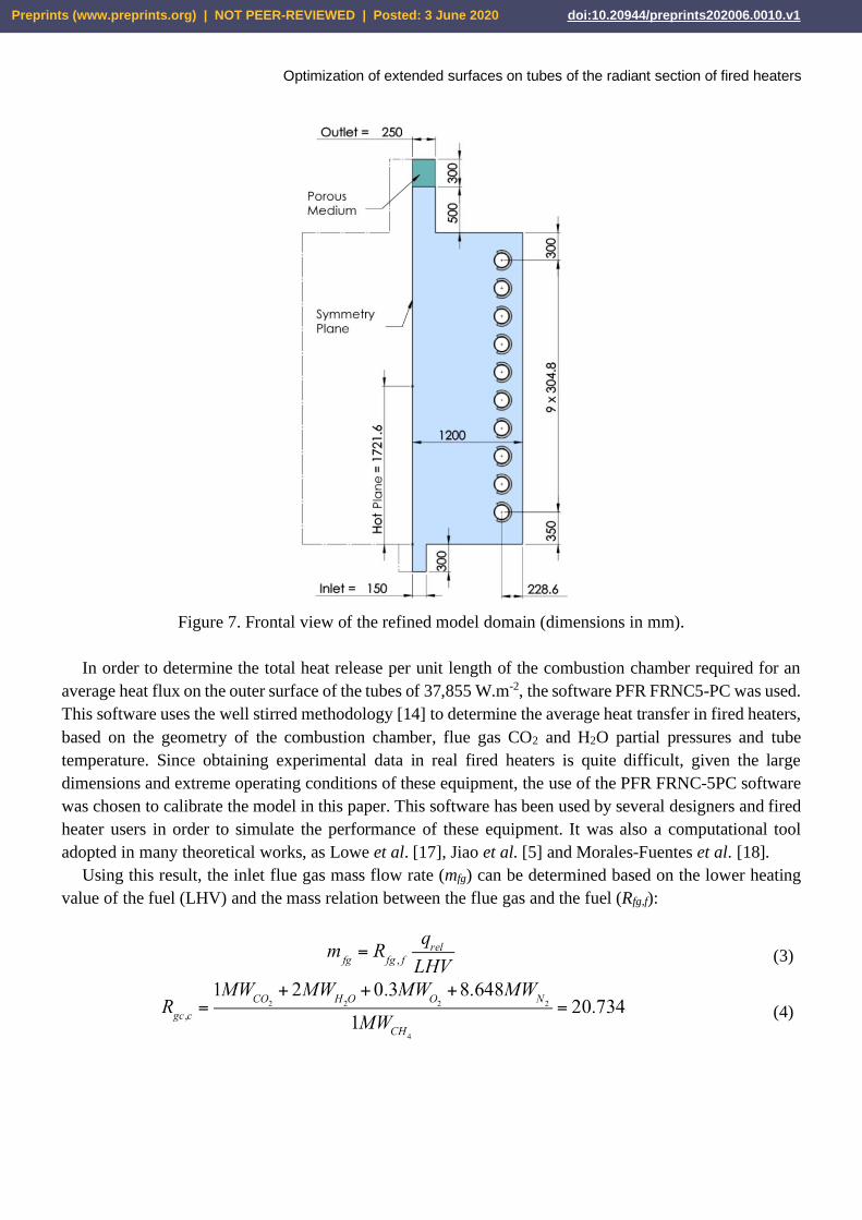
The geometry, shown in Figure 7, represents an infinite length box type combustion chamber with ten
horizontal tubes placed against the side walls.
As in the simplified model, the combustion was not modeled and the flame was approximated by a hot
plane, where the height respected the limit of 2/3 of the combustion chamber [13]. In this plane a free
surface boundary condition was adopted, avoiding wall effects on the flow. The boundary conditions used
for the other surfaces were the same considered in the simplified model. For the inlet condition a fixed gas
composition was considered according to Eq. (2). A porous medium was included at the flue gas exit in
order to simulate the pressure drop caused by the convection section tube banks.
Analyzing the energy balance in the proposed problem, the heat released in the system (qrel) is given by
the sum of the net heat transfer in the hot plane and the sensible heat of the inlet flue gas. By changing the
temperature and the flow rate of the inlet flue gas and the temperature and emissivity of the hot plane, the
boundary conditions for the tubes are changed, affecting the resulting heat flux for a given total heat
released.
Preprints (www.preprints.org) | NOT PEER-REVIEWED | Posted: 3 June 2020 doi:10.20944/preprints202006.0010.v1
Optimization of extended surfaces on tubes of the radiant section of fired heaters
Figure 7. Frontal view of the refined model domain (dimensions in mm).
In order to determine the total heat release per unit length of the combustion chamber required for an
average heat flux on the outer surface of the tubes of 37,855 W.m-2, the software PFR FRNC5-PC was used.
This software uses the well stirred methodology [14] to determine the average heat transfer in fired heaters,
based on the geometry of the combustion chamber, flue gas CO2 and H2O partial pressures and tube
temperature. Since obtaining experimental data in real fired heaters is quite difficult, given the large
dimensions and extreme operating conditions of these equipment, the use of the PFR FRNC-5PC software
was chosen to calibrate the model in this paper. This software has been used by several designers and fired
heater users in order to simulate the performance of these equipment. It was also a computational tool
adopted in many theoretical works, as Lowe et al. [17], Jiao et al. [5] and Morales-Fuentes et al. [18].
Using this result, the inlet flue gas mass flow rate (mfg) can be determined based on the lower heating
value of the fuel (LHV) and the mass relation between the flue gas and the fuel (Rfg,f):
(3)
(4)
Preprints (www.preprints.org) | NOT PEER-REVIEWED | Posted: 3 June 2020 doi:10.20944/preprints202006.0010.v1

Optimization of extended surfaces on tubes of the radiant section of fired heaters
The next step was to adjust the hot plane emissivity and temperature, which led to the same result of
average heat flux to the tubes (37,855 W.m-2) for the heat release determined by the PFR FRNC5-PC.
It is considered that the model adopted, despite the simplifications, fully meet the desired goal, which is
to provide an environment similar to that found in combustion chambers in order to obtain boundary
conditions alike those found in fired heater tubes.
3. FLUID FLOW AND HEAT TRANSFER MODELS
The ANSYS FLUENT software was used to solve the problems described above through the finite
volumes method. The models used to describe the fluid flow and heat transfer mechanisms are briefly
commented below.
3.1. Fluid flow
All simulations were performed for the steady state case. In order to include the effects of turbulence,
the realizable k- model [19] was used. This model is more adequate to represent recirculating and
expansion regions, in comparison with the standard k-. The realizable model uses a different formulation
for both the turbulent viscosity and the transport equation for the dissipation rate ().
For the wall effects on the fluid flow, the Enhanced Wall Treatment (EWT) [20], was used. This model
combines a two-layer approach with scalable wall functions, reducing the mesh refinement influence on
the results. The two-layer formulation divides the domain, defining a region affected by the presence of the
walls, where the realizable k- formulation is modified. For the control volumes adjacent to the walls, a
linear and a logarithm wall function models are combined to define the fluid flow, based on the y+
parameter
In the porous region a source term was included in the momentum conservation equation to simulate
losses due to inertial effects. The parameters were adjusted for a pressure drop of 50 Pa.
3.2. Heat transfer
The turbulent influence in the convection heat transfer was included in the enhanced wall treatment
model (EWT), as well as buoyancy effects caused by the flue gas temperature variation.
The radiation properties were obtained by the weighted sum of gray gases (WSGG) [21]. This model
simulates the spectral dependence of gases absorption coefficients based on the partial pressure of the CO2
and H2O, and the flue gas temperature.
The radiation heat transfer was evaluated by the Discrete Ordinates (DO) [22] method. This model
divides the domain into a discrete number of directions ( ), each one associated to a weight factor, where
the radiation intensity (I) transport equation has to be solved. For this study the refractive and scattering
effects were neglected, and the radiation equation was reduced to:
(5)
where the first term on the right-hand side represents the radiation intensity gain due to the gas emissions
and the second term account for the gas absorption.
Preprints (www.preprints.org) | NOT PEER-REVIEWED | Posted: 3 June 2020 doi:10.20944/preprints202006.0010.v1
Optimization of extended surfaces on tubes of the radiant section of fired heaters
The meshes were generated using only hexahedral elements through the sweep method, available in the
ANSYS Meshing software. This type of mesh allows a smaller number of control volumes for the
discretization of the domain in comparison with tetrahedral elements, reducing the computational costs.
Furthermore, the use of hexahedral elements enabled that large part of the mesh faces were aligned with
the Cartesian coordinate system, reducing numerical errors of the DO model. Proper refinement was used
in order to eliminate mesh influence on the results, especially close to the tubes as shown in Figure 7. A
total number of 17,328 integration cells were used in the simplified model and 381,876 integration cells
were used in the refined model. A second verification of the grid convergence analysis of the final results
will be presented in the next sections.
4. OPTIMIZATION MODEL
The objective function used in this study was the minimization of the Fcir factor, shown in Eq. (1),
obtained by solving the simplified model.
The optimization variables adopted were the fin base thickness (wb) and the extension angle (). Thus,
to obtain a better circumferential heat flux distribution, the Fcir ratio must be minimized.
Since the numerical solution of the finite volume models requires considerable computation time, a
response surface technique was used in order to replace the finite volume model solution in each
optimization iterative step by a fast response approximate model [23].
To this end, the finite volume model was initially solved for a number of discrete points (Pj) formed by
combinations of the variables (, wb)j in order to create a representative initial population of the evaluated
domain.
From these results, the adopted response surface (frs) was obtained by a multiquadric radial basis function
(RBF) with a second order polynomial term, given by [23]:
(6)
(7)
To obtain the j, l,k and 0 parameters, the following restrictions were imposed [23]:
(8)
(9)
(10)
Preprints (www.preprints.org) | NOT PEER-REVIEWED | Posted: 3 June 2020 doi:10.20944/preprints202006.0010.v1

Optimization of extended surfaces on tubes of the radiant section of fired heaters
The pair of variables (, wb) which minimizes the response surface was obtained by the Particle Swarm
optimization method [23,24]. The procedure is based on the social behavior of different species in nature,
using effects of individuality and sociability in order to determine an optimal search direction. The
algorithm is given by:
(11)
where k is the iteration step index, r1 and r2 are uniform random numbers varying from 0 to 1, and the
constants 1 and 2, taken as 2 in this study, define the search range. The best position obtained by the ith
individual (i) is the responsible for the individuality, and the best position obtained by all the individuals
(g) is the responsible for the sociability.
5. RESULTS
5.1. Extended surface optimization
First, the influence of the optimization variables on the heat flux distribution to the tubes was evaluated.
To this end, some cases were simulated using the trapezoidal fins. Figure 8a shows that the Fcir factor
rapidly increases for large values of . This change in behavior is explained by the displacement of the
maximum heat flux point, which goes from the tube side facing the hot plane to the fin base region, close
to the maximum value of . In all cases, wp was set to 0.635 mm as discussed before. Figure 8b shows that
trapezoidal profiles (wb>wp) generally perform better than rectangular profiles (wb=wp), justifying their use
in this application. It is also noted that within the evaluated range of variables the behavior of the objective
function is less sensitive to the fin base thickness compared to the effects of the fin extension angle.
(a) (b)
Figure 8. Variables influence in the heat flux distribution.
From these results, a searching domain was adopted with ranging from 105° to 125° and wb between
2.5 and 10 mm. For the initial population, combinations of varying in increments of 5° and wb varying in
Preprints (www.preprints.org) | NOT PEER-REVIEWED | Posted: 3 June 2020 doi:10.20944/preprints202006.0010.v1

Optimization of extended surfaces on tubes of the radiant section of fired heaters
increments of 1.25 mm were used, resulting in a total of 35 points to be evaluated by the finite volumes
model for each type of extended surface.
The obtained response surfaces are shown in Figure 9. The main difference between the two types of
extended surface was the effect of the variable wb on the heat flux distribution to the tubes, since the
parabolic profile gradients were more pronounced for small values of the fin base thickness. It is possible
to see that both response surfaces had a unimodal behavior in the evaluated domain, which would allow the
use of deterministic optimization models [23], based on the gradient of the objective function. However, as
the behavior of the objective function was not known at the beginning, the Particle Swarm model was
adopted since it has a good performance both for unimodal and multimodal functions, as confirmed from
examples obtained from literature [23]. Also, the comparison of different optimization models was not the
objective of this study.
(a) (b)
Figure 9. Response surfaces for the trapezoidal and parabolic fin profiles.
Using the Particle Swarm optimization method it was possible to obtain the following optimum
parameters for the two types of fins studied: wb = 5.2 mm and = 114.1° for the trapezoidal profile, and
wb = 6.3 mm and = 115.0° for the parabolic profile. These two configurations were evaluated in the
physical model and the relative errors obtained, compared to the results predicted by the response surfaces,
were 3.3×10⁻⁵ and 7.6×10⁻⁵ for the trapezoidal and parabolic profiles respectively, indicating a good
accuracy of the RBF model based on the selected initial populations.
A comparison between the heat flux distribution obtained with the trapezoidal fin and the bare tube is
illustrated in Figure 10 (the results obtained for the parabolic fin were very similar). It’s possible to see that
the fin promotes an increase in heat flux, especially in the region close to the maximum angle. Also, the
value of the maximum heat flux (represented by the discontinuous red line) is not exceeded, which would
increase the Fcir factor, as shown in Figure 8a for high values.
Preprints (www.preprints.org) | NOT PEER-REVIEWED | Posted: 3 June 2020 doi:10.20944/preprints202006.0010.v1

Optimization of extended surfaces on tubes of the radiant section of fired heaters
Figure 10. Heat flux distribution along the inner surface of the bare tube and with the optimized
trapezoidal fin.
These results led to a reduction of the difference between the maximum and mean heat flux of 17% with
the trapezoidal profile and 16% with the parabolic profile. However, the parabolic fin obtained with the
optimization method resulted in a total volume 24.8% lower than that obtained with the trapezoidal profile,
which could allow the production of a more economical and light equipment.
An analysis of the temperature profile, presented in Figure 11, revealed that for the considered conditions
the maximum temperature obtained for the fins was less than 475 oC. Therefore, for the considered
conditions the fins did not reach the temperature limits recommended for low Cr steels [13]. However, in
more severe applications the use of stainless steel may be required.
Figure 11. Temperature distribution with the optimized trapezoidal fin.
5.2. Evaluation in the refined model
The software PFR FRNC-5PC has determined a heat release per unit length of the radiation chamber
proposed in the refined model of 709 kW.m-1 to obtain an average heat flux of 37,855 W.m-2 on the tubes.
Preprints (www.preprints.org) | NOT PEER-REVIEWED | Posted: 3 June 2020 doi:10.20944/preprints202006.0010.v1

Optimization of extended surfaces on tubes of the radiant section of fired heaters
From this result, the emissivity and temperature of the hot plane were adjusted to 0.15 and 1388 °C in order
to provide the same results in the refined finite volume model.
The ratio between the higher average heat flux among the 10 tubes (qmax
) and the total average heat flux
( q ) was 1.23, which is consistent with the 1.0-1.5 range recommended for the FL factor [12] defined in Eq.
(12).
(12)
Convection was responsible for 11.4% of the heat transfer to the tubes, a result close to the typical value
of 15% found in the literature [9]. Thus, the proposed refined model attends the purpose of providing
boundary conditions for the tubes close to those found in fired heaters.
The fins obtained by the optimization method applied to the simplified model were introduced into the
refined model in order to evaluate the impact of including the effects of convective heat transfer and the
position of the tubes within the combustion chamber.
Results presented in Figure 12 show that the two types of evaluated fins obtained performances very
close to each other, providing a significant decrease of the Fcir factor for tubes 1 to 8, where tube 1 is the
closest one to the combustion chamber floor. However, for tubes 9 and 10 the heat flux distribution was
not very good.
Figure 12. Comparison of the circumferential heat flux distribution to the tubes.
Figure 13 shows that these tubes are positioned into a recirculation zone, subject to a direct incidence of
the flue gases. This fact leads to an excessive value for the maximum heat flux obtained with bare tubes on
its upper surface, as shown in Figure 14.
Preprints (www.preprints.org) | NOT PEER-REVIEWED | Posted: 3 June 2020 doi:10.20944/preprints202006.0010.v1

Optimization of extended surfaces on tubes of the radiant section of fired heaters
Figure 13. Flow representation and temperature profiles.
(a) (b)
Figure 14. Heat flux distribution along the inner surface of tubes 9 and 10.
Preprints (www.preprints.org) | NOT PEER-REVIEWED | Posted: 3 June 2020 doi:10.20944/preprints202006.0010.v1

Optimization of extended surfaces on tubes of the radiant section of fired heaters
In order to re-check the grid convergence, we re-ran these results, obtained with 376,086 cells, in a grid
with 761,568 cells. The comparison between the two grids is presented in Table 1, where one can verify
that relative deviations in the average and maximum heat flux, as well as in the Fcir are less than 1%.
Table 1. Grid convergence analysis of the results presented in Fig. 12.
q
(W/m2) Deviation
qmax
(W/m2)
Deviation
Fcir
(-)
Deviation
Tube
Mesh size Mesh size Mesh size
376,086
cells
761,568
cells
376,086
cells
761,568
cells
376,086
cells
761,568
cells
1 52632 52558 0.14% 69562 69734 0.25% 1.3217 1.3268 0.39%
2 48273 48374 0.21% 73031 73408 0.51% 1.5129 1.5175 0.31%
3 45997 45971 0.06% 70649 70792 0.20% 1.5360 1.5399 0.26%
4 43895 43899 0.01% 66971 67406 0.65% 1.5257 1.5355 0.64%
5 41078 41096 0.04% 61839 62306 0.75% 1.5054 1.5161 0.70%
6 38739 38729 0.03% 55402 55444 0.08% 1.4301 1.4316 0.10%
7 36967 37093 0.34% 49281 49440 0.32% 1.3331 1.3329 0.02%
8 35519 35554 0.10% 43802 43810 0.02% 1.2332 1.2322 0.08%
9 39571 39767 0.49% 62664 63054 0.62% 1.5836 1.5856 0.13%
10 46330 46198 0.29% 72679 72694 0.02% 1.5687 1.5735 0.31%
A new optimization process was carried out in order to adjust the parameter of the upper face of tubes
9 and 10. To this task, only the trapezoidal profile was considered, since the parabolic profile results were
very similar. New simulations were performed and a cubic spline interpolation was used to fit the data.
After identifying the region where the minimum objective function was located at, the geometries of the
tubes 9 and 10 were optimized using the Particle Swarm method.
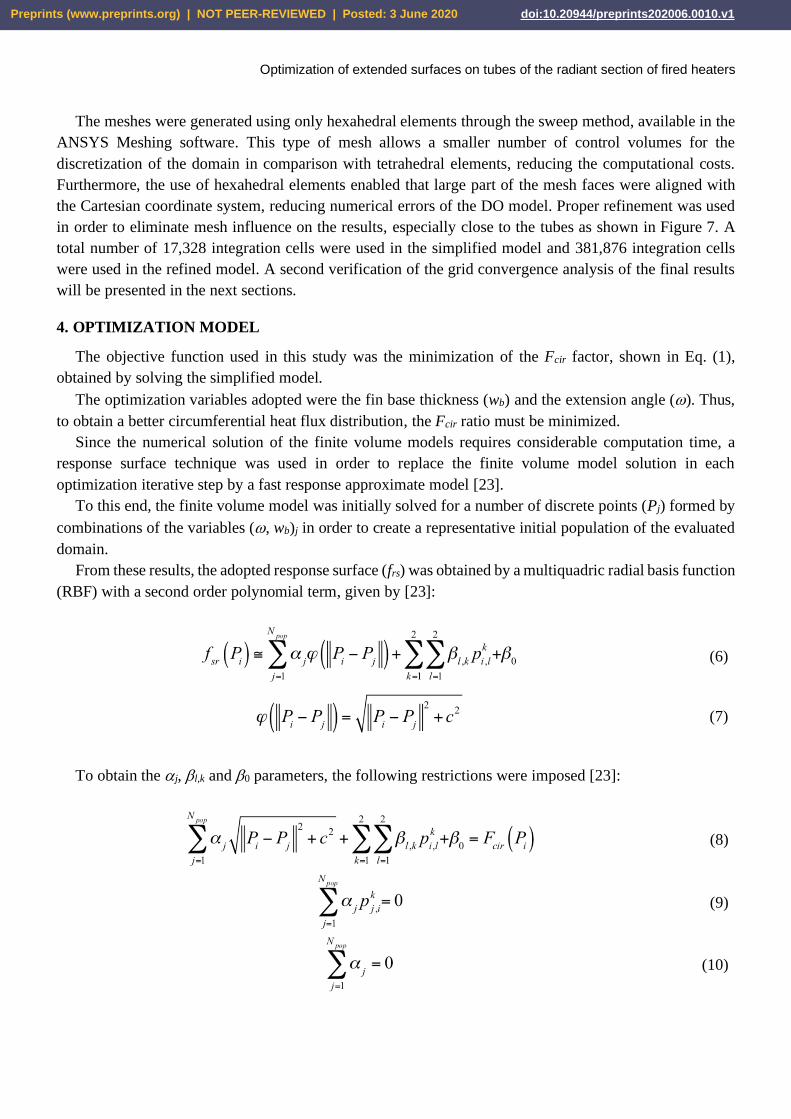
The results of this optimization procedure are shown in Figures 15 and 16. It is possible to observe a
significant improvement in the uniformity of heat flux distribution to all tubes. The average reduction of
the difference between the maximum and average heat flux was 28.1%. The highest value obtained for the
Fcir factor was 1.53, a significant reduction compared to the maximum value of 1.67 obtained with bare
tubes. These results could be further improved with an individualized optimization of the other tubes, but
the potential gain would be lower than those obtained for the tubes 9 and 10.
Preprints (www.preprints.org) | NOT PEER-REVIEWED | Posted: 3 June 2020 doi:10.20944/preprints202006.0010.v1
Optimization of extended surfaces on tubes of the radiant section of fired heaters
Figure 15. Circumferential heat flux distribution to the tubes.
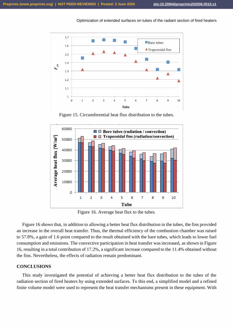
Figure 16. Average heat flux to the tubes.
Figure 16 shows that, in addition to allowing a better heat flux distribution in the tubes, the fins provided
an increase in the overall heat transfer. Thus, the thermal efficiency of the combustion chamber was raised
to 57.8%, a gain of 1.6 point compared to the result obtained with the bare tubes, which leads to lower fuel
consumption and emissions. The convective participation in heat transfer was increased, as shown in Figure
16, resulting in a total contribution of 17.2%, a significant increase compared to the 11.4% obtained without
the fins. Nevertheless, the effects of radiation remain predominant.
CONCLUSIONS
This study investigated the potential of achieving a better heat flux distribution to the tubes of the
radiation section of fired heaters by using extended surfaces. To this end, a simplified model and a refined
finite volume model were used to represent the heat transfer mechanisms present in these equipment. With
Preprints (www.preprints.org) | NOT PEER-REVIEWED | Posted: 3 June 2020 doi:10.20944/preprints202006.0010.v1
Optimization of extended surfaces on tubes of the radiant section of fired heaters
these results, a response surface technique and the Particle Swarm optimization method were used to
determine the best geometric configurations for the proposed fin profiles.
The results obtained with the simplified model, which only considered radiative heat transfer, led to a
reduction of the difference between the maximum and average heat flux on the internal tubes of the heater
of 17% with the trapezoidal profile and 16% with the parabolic profile. When the effects of convection
were included with the refined model, the gains were even greater, allowing an average reduction of the
difference between the maximum and average heat flux per tube of about 28%.
These results indicate that the use of extended surfaces in the tubes of the radiation section of fired
heaters has the potential to significantly improve the heat flux distribution, reducing the risk factors that
lead to the harmful processes of fluid degradation and coking. Thus, this application makes possible the
design of combustion chambers with smaller dimensions and number of tubes, since it allows an increase
in the average heat flux for a given maximum limit. It can also be an interesting alternative to services that
require a more uniform heat flux distribution, especially compared to the complex double fired arrangement.
In existing fired heaters, the replacement of bare tubes by finned tubes allows increased thermal efficiency
and/or energy transfer capacity, without extrapolating the maximum heat flux recommended for the
application.
Future studies may investigate new geometries for the extended surfaces, seeking for an even better heat
flux distribution to the tubes. In addition, experimental evaluations may be performed in order to confirm
the results predicted in this work.
ACKNOWLEDGEMENTS
This work was partly funded by the Brazilian agencies CNPq, CAPES, FAPERJ, and ANP/PRH. The
support provided by PETROBRAS is also greatly appreciated.
REFERENCES
[1] BARLETTA, T., “Why Vacuum Unit Fired Heaters Coke”, Petroleum Technology Quarterly, Q4,
2002.
[2] JEGLA, Z., KAHOUTEK, J., STEHLIK, P., “Design and Operating Aspects Influencing Fouling
Radiant Coils of Fired Heaters Operated in Crude Oil Distilation Plants”, In: Proceedings on
International Conference on Heat Exchanger Fouling and Cleaning, pp. 7-14, 2011.
[3] PELINI, R. G., “Heat Flux And Film Temperature In Fired, Thermal-Fluid Heaters”, Chemical
Engineering, v. 115, n. 13, pp. 34-40, Dec. 2008.
[4] CATALA, K. A., KARRS, M. S., SIELI, G., “Advances in Delayed Coking Heat Transfer Equipment”,
Hydrocarbon Processing, pp. 45-54, Feb. 2009.
[5] JIAO, J., MORAYKO, Y., THAILGAARD, M., et al., “Controlling Film Temperature in Fired
Heaters”, Petroleum Technology Quarterly, Q1, 2013.
[6] WEN, J. X., HUANG, M. Y., “CFD Modelling of Confined Jet Fires under Ventilation-Controlled
Conditions”, Fire Safety Journal, v. 34, n. 1, pp. 1-24, Feb. 2000.
[7] ORBEGOSO, E. M. M., Numerical Study of Thermal Radiation and its Interaction with the Soot
Formed in Turbulent Combustion Fuels Liquid and Gaseous, PhD Thesis (in Portuguese), Pontifical
Catholic University of Rio de Janeiro, Rio de Janeiro, RJ, Brazil, 2013.
Preprints (www.preprints.org) | NOT PEER-REVIEWED | Posted: 3 June 2020 doi:10.20944/preprints202006.0010.v1
Optimization of extended surfaces on tubes of the radiant section of fired heaters
[8] COELHO, P. J., “Advances in the Discrete Ordinates and Finite Volume Methods for the Solution of
Radiative Heat Transfer Problems in Participating Media”, Journal of Quantitative Spectroscopy &
Radiative Transfer, v. 145, pp. 121-146, 2014.
[9] STEFANIDIS, G. D., MERCI, B., HEYNDERICKX, et al., “CFD Simulations of Steam Cracking
Furnaces using Detailed Combustion Mechanisms”, Computers and Chemical Engineering, v. 30, n.
4, pp. 635-649, Feb. 2006.
[10] LAN, X., GAO, J., XU, C., et al., “Numerical Simulation of Transfer and Reaction Processes in
Ethylene Furnaces”, Chemical Engineering Research and Design, v. 85, n. 12, pp. 1565-1579, 2007.
[11] HÁJEK, J., JEGLA, Z., VONDÁL, J., “Numerical Analysis of Radiant Section of Fired Heater
Focused on the Effect of Wall-Tube Distance”, In: Proceedings of the 24th European Symposium on
Computer Aided Process Engineering – ESCAPE 24, pp. 331–336, Budapest, Jun. 2014.
[12] API STD 530, Calculation of Heater Tube Thickness in Petroleum Refineries, 6th ed., American
Petroleum Institute, 2008.
[13] API STD 560, Fired Heaters for General Refinery Service, 4th ed., American Petroleum Institute, 2007.
[14] LOBO, W. E., EVANS, J. E., “Heat Transfer in Radiant Section of Petroleum Heaters”, Transactions
of the American Institute of Chemical Engineers, v. 35, pp. 748-778, 1939.
[15] BERMAN, H. L., “How Combustion Conditions Influence Design and Operation”, Chemical
Engineering, v. 85, n. 18, pp. 129-140, Ago. 1978.
[16] BENKO, I., “Energy Conservation Through Increased Emissivity in Furnaces”, Periodica
Polytechnica Mechanical Engineering, v. 35, n. 4, pp. 235-245, 1991.
[17] LOWE, C., BRANCACCIO, N., BATTEN, D., et al., “Technology Assessment of Hydrogen Firing of
Proccess Heaters”, Energy Procedia, v. 4, pp. 1058-1065, 2011.
[18] MORALES-FUENTES, A., PICÓN-NÚÑEZ, M., POLLEY, G. T., et al., “Analysis of the Influence
of Operating Conditions on Fouling Rates in Fired Heaters”, Applied Thermal Engineering, v. 62, n.
2, pp. 777-784, 2014.
[19] SHIH, T. H., LIOU, W. W., SHABBIR, A., et al., “A New k- Eddy Viscosity Model for High
Reynolds Number Turbulent Flows”, Computers & Fluids, v. 24, n. 3, pp. 227-238, Mar. 1995.
[20] ANSYS, INC., ANSYS FLUENT Theory Guide, v. 14.0, Canonsburg, Nov. 2011.
[21] HOTTEL, H. C., SAROFIM, A. F., Radiative Transfer, 1st ed., New York, McGraw Hill, 1967.
[22] CHANDRASEKHAR, S., Radiative Transfer, 1st ed., New York, Dover Publication, 1960.
[23] COLAÇO, M. J., DULIKRAVICH, G. S., “A Survey of Basic Deterministic, Heuristic, and Hybrid
Methods for Single-Objective Optimization and Response Surface Generation”, In: ORLANDE, H. R.
B., MAILLET, O. F. D., COTTA, R. M. (eds), Thermal Measurements and Inverse Techniques, 1st ed.,
cap. 10, EUA, CRC Press, 2011.
[24] KENNEDY, J. ELBERHART, R. C., “Particle Swarm Optimization”, In: Proceedings of the 1995
IEEE International Conference on Neural Networks, v. 4, pp. 1942-1948, Perth, Australia, 1995.
Preprints (www.preprints.org) | NOT PEER-REVIEWED | Posted: 3 June 2020 doi:10.20944/preprints202006.0010.v1