Embed Size (px)
Citation preview
Express diagnostics of WWER fuel rods at nuclear power plants
S.V.Pavlov, S.V.Amosov, S.S.Sagalov, A.N.Kostyuchenko
8th International Conference on WWER Fuel Performance, Modelling and Experimental Support
26 September – 04 October 2009, Helena Resort near Burgas, Bulgaria
JSC “State Scientific Center- Research Institute of Atomic Reactors”
2 CONTENTS
INTRODUCTION
1. Ultrasonic testing of failed fuel rods (FR) in WWER fuel assemblies (FA)
2. Eddy current testing of FR claddings
3. Method of determination of the diametrical fuel-cladding gap
4. Method of oxide film thickness measurement on the FR cladding outer surface
CONCLUSION
3 INTRODUCTION
1. The efficiency of technological support for standard fuel operation and new fuel introduction depends on the completeness of irradiated fuel data in many respects as well as on the rapidity and cost of such data obtaining.
2. In order to increase the comprehensiveness of primary data on fuel assemblies and fuel rods immediately after their removal from the reactor, inspection test facilities are widely used for these purposes. The inspection test facilities make it possible to perform non-destructive inspection of fuel in the NPP cooling pools .
3. Specifically, non-destructive inspection of fuel rods at the inspection stands is conducted by different optical, ultrasonic and other methods.
4 INTRODUCTION
4. For inspection of the WWER-1000 fuel rods, methods of ultrasonic testing of failed fuel rods and eddy current testing of FR claddings have been developed and proved. These methods are used at the stands for inspection and repair of TVSA at the Kalinin and Temelin NPP.
5. Method of determination of a diametrical fuel-cladding gap and an electromagnetic method of the oxide film thickness measurement on the FR cladding outer surface have been successfully used at RIAR for examination of irradiated WWER fuel for many years. These methods could be easily accommodated for underwater operation of the inspection stands.
5 Ultrasonic testing of failed fuel rods
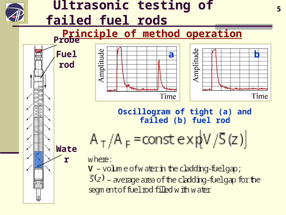
Principle of method operationProbe
Fuel rod
Water
Oscillogram of tight (а) and failed (b) fuel rod
а b
6 Ultrasonic testing of failed fuel rods
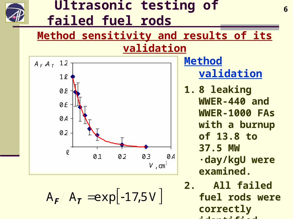
Method sensitivity and results of its validation
Method validation
1. 8 leaking WWER-440 and WWER-1000 FAs with a burnup of 13.8 to 37.5 MW ·day/kgU were examined.
2. All failed fuel rods were correctly identified.
V5,17expАА TF
0,0
0.2
0.4
0.6
0.8
1.0
1.2
0,0 0.1 0.2 0.3 0.4 V , cm
3
А F / А T
0
7 Ultrasonic testing of failed fuel rods
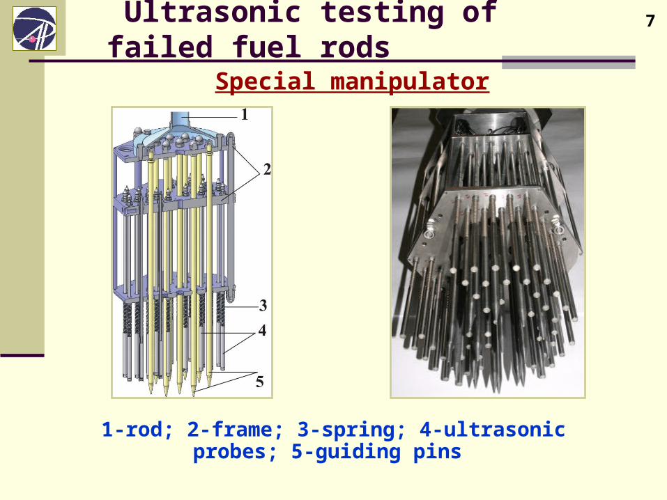
Special manipulator
1-rod; 2-frame; 3-spring; 4-ultrasonic probes; 5-guiding pins
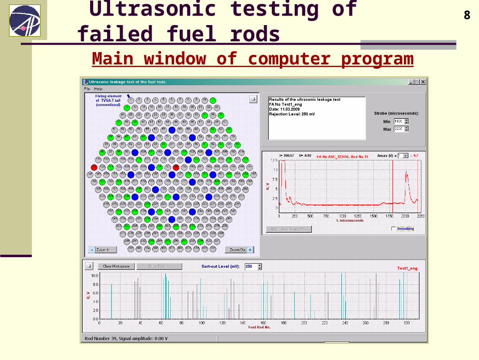
8 Ultrasonic testing of failed fuel rods
Main window of computer program
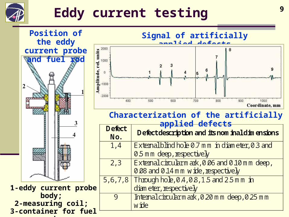
9 Eddy current testing
Position of the eddy current probe
and fuel rod
1-eddy current probe body; 2-measuring coil;
3-container for fuel rod; 4-fuel rod
Signal of artificially applied defects
Characterization of the artificially applied defects
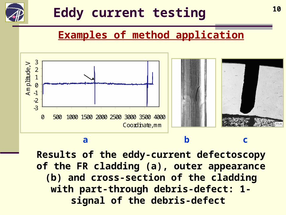
10 Eddy current testing
Examples of method application
а b c
Results of the eddy-current defectoscopy of the FR cladding (а), outer appearance (b) and cross-section of
the cladding with part-through debris-defect: 1-signal of the debris-defect
-3-2-10123
0 500 1000 1500 2000 2500 3000 3500 4000Coordinate, mm
Am
plit
ude,
V
1
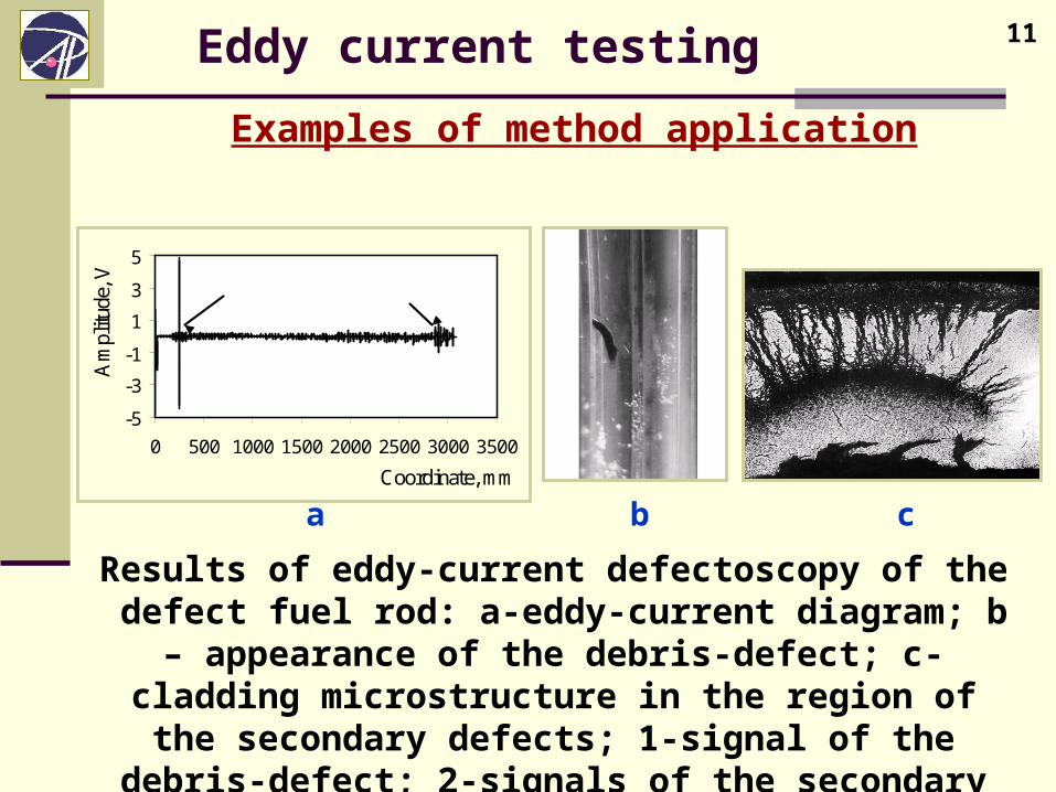
11 Eddy current testing
Examples of method application
а b c
Results of eddy-current defectoscopy of the defect fuel rod: а-eddy-current diagram; b – appearance of the debris-defect;
c-cladding microstructure in the region of the secondary defects; 1-signal of the debris-defect; 2-signals of the
secondary internal defects
-5
-3
-1
1
3
5
0 500 1000 1500 2000 2500 3000 3500
Coordinate, mm
Am
plitu
de, V
1 2
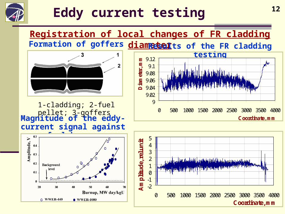
12 Eddy current testing
Registration of local changes of FR cladding diameterResults of the FR cladding testingFormation of goffers
Magnitude of the eddy-current signal against fuel burnup
1-cladding; 2-fuel pellet; 3-goffers
-
99.029.049.069.089.1
9.12
0 500 1000 1500 2000 2500 3000 3500 4000
Coordinate, mm
Dia
met
er, m
m
-2-1012345
0 500 1000 1500 2000 2500 3000 3500 4000Coordinate, mm
Am
pli
tud
e, r
el.u
nit
s
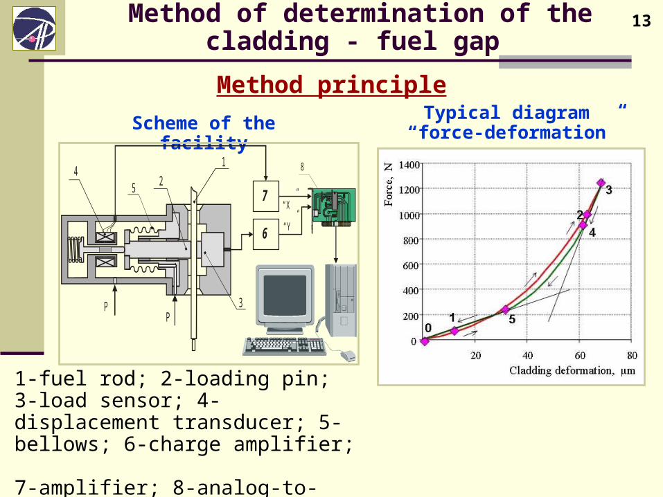
13 Method of determination of the cladding - fuel gap
Method principleTypical diagram
“force-deformation”Scheme of the facility
6
1
24
3
5“X ”
“Y ”
8
7
PP
1-fuel rod; 2-loading pin;3-load sensor; 4-displacement transducer; 5-bellows; 6-charge amplifier; 7-amplifier; 8-analog-to-digital converter
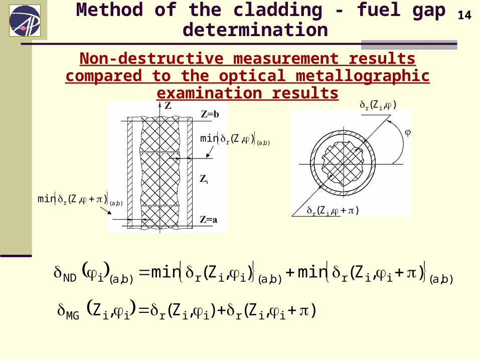
14 Method of the cladding - fuel gap determination
Non-destructive measurement results compared to the optical metallographic examination results
)b,a(r ),Z(min
)b,a(r ),Z(min
),Z( ir
),Z( ir
)b,a(iir)b,a(iir)b,a(iND ),Z(min),Z(min
),Z(),Z(,Z iiriiriiMG
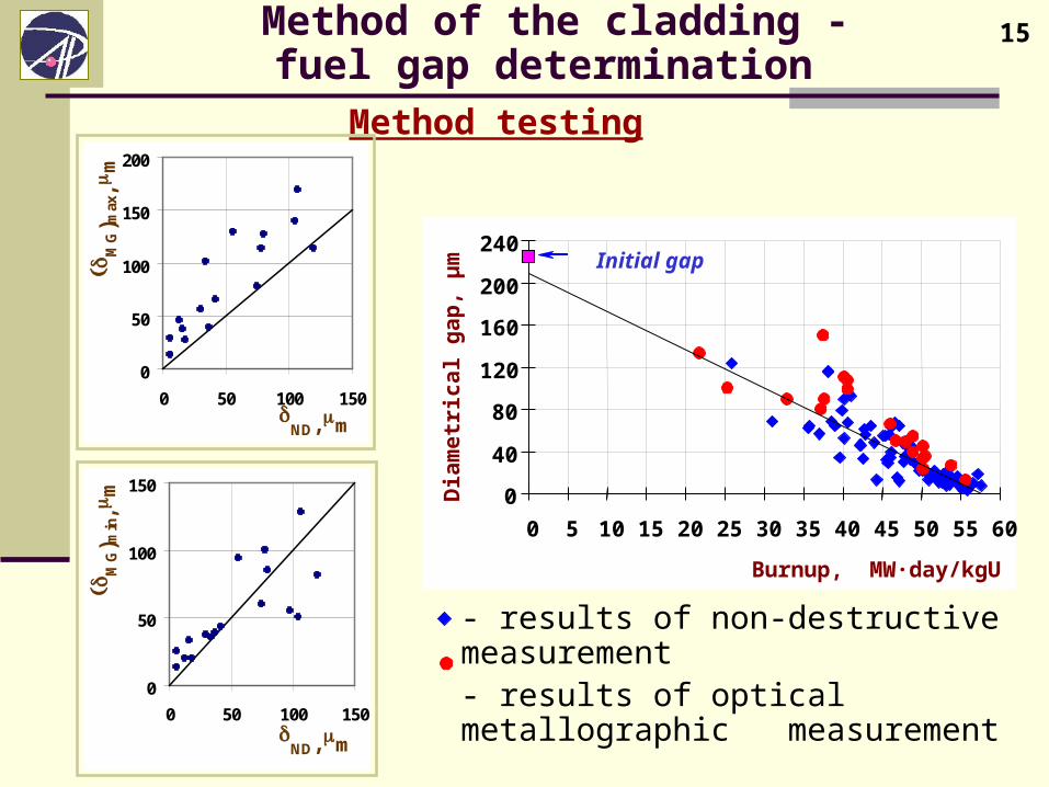
15 Method of the cladding - fuel gap determination
Method testing
- results of non-destructive measurement- results of optical metallographic measurement
0
40
80
120
160
200
240
0 5 10 15 20 25 30 35 40 45 50 55 60
Burnup, MW·day/kgU
Dia
met
rica
l gap
, µm
Initial gap
0
50
100
150
200
0 50 100 150
ND, mm
M
G) m
ax, m
m
0
50
100
150
0 50 100 150
ND, mm
M
G) m
in, m
m
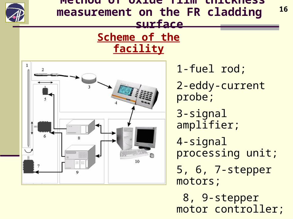
16 Method of oxide film thickness measurement on the FR cladding surface
Scheme of the facility
1-fuel rod;
2-eddy-current probe;
3-signal amplifier;
4-signal processing unit;
5, 6, 7-stepper motors;
8, 9-stepper motor controller;
10-computer.
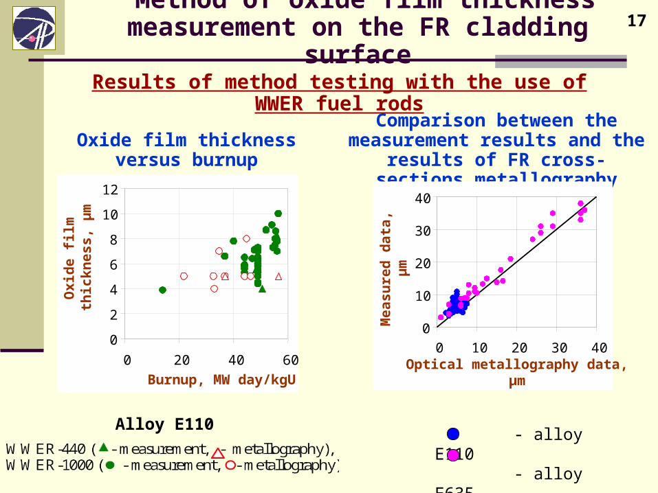
17 Method of oxide film thickness measurement on the FR cladding surface
Results of method testing with the use of WWER fuel rods
Comparison between the measurement results and the results of FR cross-sections metallography
Oxide film thickness versus burnup
Alloy E110 - alloy E110 - alloy E635
0
2
4
6
8
10
12
0 20 40 60
Burnup, МW day/kgU
Oxi
de
film
th
ick
nes
s, µ
m
0
10
20
30
40
0 10 20 30 40Optical metallography data,
µmM
easu
red
dat
a,
µm
18 CONCLUSION
1. The ultrasonic testing of failed fuel rods inside the fuel assembly was developed for stands of inspection and repair of TVSA WWER-1000 for the Kalinin NPP and Temelin NPP.
2. This method was tested for eight leaking fuel assemblies WWER-440 and WWER-1000 with a burnup of ~14 up to 38 MWday/kgU. The ultrasonic testing proved its high degree of reliability and efficiency.
19 CONCLUSION
3. The defectoscopy by means of the pulsed eddy-current method was adapted for the stand of inspection and repair of TVSA WWER-1000 for the Kalinin NPP. This method has been used at RIAR as an express testing method of FR claddings during the post-irradiation examinations of fuel assemblies WWER-440 and WWER-1000. This testing method was used for examination of 47 spent WWER fuel assemblies in total. But there were 16 failed spent fuel assemblies among them .
4. Methods of oxide film thickness measurement and fuel-cladding gap measurement in the WWER fuel rods have been successfully used for examination of the WWER fuel in hot cells. They can be easily adapted for use under water and can be recommended for adoption at stands of inspection and repair of TVSA WWER-1000
20
THANK YOU FOR ATTENTION!