Embed Size (px)
Citation preview

IAEA-TECDOC-1492
Improvements ofradioactive waste management at
WWER nuclear power plants
April 2006

IAEA-TECDOC-1492
Improvements ofradioactive waste management at
WWER nuclear power plants
April 2006
The originating Section of this publication in the IAEA was:
Waste Technology Section International Atomic Energy Agency
Wagramer Strasse 5 P.O. Box 100
A-1400 Vienna, Austria
IMPROVEMENTS OF RADIOACTIVE WASTE MANAGEMENT AT WWER NUCLEAR POWER PLANTS
IAEA, VIENNA, 2006 IAEA-TECDOC-1492 ISBN 92–0–103006–1
ISSN 1011–4289 © IAEA, 2006
Printed by the IAEA in Austria April 2006

FOREWORD
This report is part of a systematic IAEA effort to improve waste management practices at WWER plants and to make them consistent with the current requirements and standards for safe and reliable operation of nuclear power plants. The report reviews the wet and dry solid waste management practices at the various types of WWER nuclear power plants (NPP) and describes approaches and recent achievements in waste minimization. Waste minimization practices in use at western PWRs are reviewed and compared, and their applicability at WWER plants is evaluated.
Radioactive waste volume reduction issues and waste management practices are
reflected in many IAEA publications. However, aspects of waste minimization specific to individual WWER nuclear power plant designs and WWER waste management policies are not addressed extensively in those publications. This report covers the important aspects applicable to the improvement of waste management at WWER NPP, including both plant-level and country-level considerations. It is recognized that most WWER plants are already implementing many of these concepts and recommendations with varying degrees of success; others will benefit from the included considerations. The major issues addressed are:
— Review of current waste management policies and practices related to WWERs and
western PWRs, including the influence of the original design concepts and significant modifications, liquid waste discharge limits and dry solid waste clearance levels applied in individual countries, national policies and laws, and other relevant aspects affecting the nature and quantities of waste arisings;
— Identification of strategies and methods for improving the radioactive waste management generated in normal operation and maintenance at WWERs.
This report is a composite (combination) of the two separate initiatives mentioned
above. The first draft report was prepared at the meeting 26–30 May 1997 by five consultants, L.R. Fellingham (UK), I. Kallonen (Finland), V. Luppov (Russian Federation), P. Kopecky (Czech Republic) and P. Ormai (Hungary). The draft was improved during an extended consultants meeting held in November 1999. Ten experts from eight Member States representing most of the countries operating power plants with WWER reactors attended this meeting. Additional work was performed at the meeting 3–7 April 2000 by the group of consultants, I. Kallonen (Finland), I. Smiesko (Slovakia) and J.J. Kelly (USA).
The initial draft of the second report was prepared by four consultants, J. Kelly (USA),
I. Kallonen (Finland), I. Smiesko (Slovakia) and J. Schunk (Hungary). The draft was updated 14–18 June 2004 by eleven radioactive waste management experts from nine Member States.
Due to their very similar nature and subject matter, the two reports were merged into a
single TECDOC by J. Kelly (USA) in April 2005. The resulting report was finalized in the meeting 5–9 September 2005 by the above four radioactive waste management experts from Finland, Hungary, Slovakia and USA.
The IAEA wishes to express its appreciation to all those, who took part in the
preparation and publication of this publication, including those who participated in the work performed on the draft versions of the original reports. The IAEA officers responsible for this report were R. Burcl and J.L. González Gómez of the Division of Nuclear Fuel Cycle and Waste Technology.

EDITORIAL NOTE
The use of particular designations of countries or territories does not imply any judgement by the publisher, the IAEA, as to the legal status of such countries or territories, of their authorities and institutions or of the delimitation of their boundaries.
The mention of names of specific companies or products (whether or not indicated as registered) does not imply any intention to infringe proprietary rights, nor should it be construed as an endorsement or recommendation on the part of the IAEA.

CONTENTS
1. INTRODUCTION ............................................................................................................ 1
1.1. Background ............................................................................................................ 1 1.2. Objectives............................................................................................................... 2 1.3. Scope of the TECDOC........................................................................................... 2 1.4. Approach ................................................................................................................ 3 1.5. Key definitions ....................................................................................................... 3 1.6. Plant-specific experience appendices ..................................................................... 4
2. NATIONAL POLICY AND MANAGEMENT SUPPORT IMPACTS ON THE SCOPE AND SUCCESS OF LILW MINIMIZATION PROGRAMMES..................................... 5
2.1. Overview ................................................................................................................ 5 2.2. National waste minimization policies .................................................................... 5 2.3. Legislative restrictions or prohibitions................................................................... 6 2.4. Storage and disposal considerations....................................................................... 7 2.5. Economic factors.................................................................................................... 7 2.6. NPP operating priorities ......................................................................................... 8 2.7. Plant design and historical operating considerations ............................................. 8 2.8. Locally available and regional technologies........................................................... 9 2.9. Commercial conditioning and disposal facilities ................................................... 9
3. LIQUID AND WET SOLID WASTES.......................................................................... 10
3.1. Primary radioactive wet solid waste generation and sources ............................... 10 3.1.1. Wet solid waste quantities and sources .................................................... 10 3.1.2. Discussion of wet solid waste types ......................................................... 10
3.2. Liquid and wet solid waste source reduction approaches .................................... 11 3.2.1. Liquid waste clearance levels................................................................... 11 3.2.2. Liquid and wet solid waste reuse/recycle programmes ............................ 12 3.2.3. Liquid and wet solid waste types and good source reduction practices ... 12
3.3. Volume reduction and conditioning technologies................................................ 14 3.3.1. Wet solid waste design concept and practice at WWERs ........................ 14 3.3.2. Dry solid waste design concept and practice at WWERs......................... 14 3.3.3. Wet and dry solid waste types and related processing technologies ........ 14
4. DRY SOLID WASTES .................................................................................................. 15
4.1. Solid radioactive waste sources and clearance levels........................................... 15 4.1.1. Dry solid waste generation and types ....................................................... 15 4.1.2. Exempted waste and clearance levels ...................................................... 15
4.2. Solid radioactive waste source reduction approaches .......................................... 17
5. SUMMARY COMPARISONS OF WWER AND PWR WASTE MANAGEMENT PRACTICES ..................................................................................... 19
5.1. Wet solid waste source reduction, volume reduction, and conditioning technologies ................................................................................... 19
5.1.1. Design concept and practice at WWERs.................................................. 19 5.1.2. Liquid and wet solid waste source reduction approaches ........................ 19 5.1.3. Wet solid waste volume reduction and conditioning technologies .......... 20
5.2. Dry solid waste source reduction and volume reduction and conditioning technologies ................................................................................... 22
5.2.1. Dry solid waste source reduction approaches........................................... 22 5.2.2. Dry solid waste volume reduction and conditioning technologies........... 24
5.3. Centralized processing facilities........................................................................... 26
6. TRENDS AND ALTERNATIVE WASTE VOLUME REDUCTION AND CONDITIONING TECHNOLOGIES USED BY WESTERN PWRs ........................... 28
6.1. Historical trends and perspectives........................................................................ 28 6.2. Western PWR waste management today and tomorrow ...................................... 31 6.3. Advanced and common technologies................................................................... 32
6.3.1. Contaminated area reduction.................................................................... 32 6.3.2. Clearance programmes ............................................................................. 33 6.3.3. Recycling for in-plant reuse, and the elimination of plastics ................... 33 6.3.4. Dissolvable materials ............................................................................... 33 6.3.5. Glassification for dry solid wastes ........................................................... 33 6.3.6. Oil incineration, clay immobilization....................................................... 34 6.3.7. Ion-selective filters ................................................................................... 34 6.3.8. Filter shredders and shears ....................................................................... 34 6.3.9. Steam reforming and conversion reforming............................................. 34 6.3.10. Dewatering .............................................................................................. 35
7. STRATEGIES AND METHODS FOR IMPROVING RADIOACTIVE WASTE MINIMIZATION AT WWERs....................................................................................... 36
7.1. National regulations and policies ......................................................................... 38 7.1.1. Minimum standards.................................................................................. 38 7.1.2. Recommendation for additional improvement......................................... 39
7.2. Implementation of industry-wide performance standards .................................... 40 7.2.1. Dry solid wastes ....................................................................................... 40 7.2.2. Wet solid wastes....................................................................................... 41 7.2.3. Liquid organic wastes............................................................................... 43 7.2.4. Additional industry-wide standards and recommendations ..................... 43
7.3. Evaluation and implementation of advanced volume reduction and conditioning technologies...................................................................................... 44
7.4. Disposal considerations which impact on waste minimization............................ 47 7.4.1. Actions by national authorities and NPP which relate to waste disposal and which encourage waste minimization................................................ 48
8. CONCLUSIONS............................................................................................................. 50
APPENDIX A: MOST COMMONLY USED WASTE VOLUME REDUCTION AND CONDITIONING TECHNOLOGIES FOR WWER AND
PWR PLANTS ............................................................................................... 53
APPENDIX B: RADIOACTIVE WASTE MANAGEMENT AT LOVIISA NUCLEAR POWER PLANT ............................................................................................. 57
APPENDIX C: RADIOACTIVE WASTE MANAGEMENT AT PAKS NUCLEAR POWER PLANT ............................................................................................ 59

APPENDIX D: RADIOACTIVE WASTE MANAGEMENT AT BOHUNICE NUCLEAR POWER PLANT ........................................................................ 65
APPENDIX E: RADIOACTIVE WASTE MANAGEMENT AT KOZLODUY NUCLEAR POWER PLANT ........................................................................ 69
APPENDIX F: RADIOACTIVE WASTE MANAGEMENT AT DUKOVANY AND TEMELIN NUCLEAR POWER PLANTS..................................................... 73
APPENDIX G: RADIOACTIVE WASTE MANAGEMENT AT BUSHEHR NUCLEAR POWER PLANT ........................................................................ 75
APPENDIX H: RADIOACTIVE WASTE MANAGEMENT PROGRAMME FOR UKRAINE NUCLEAR POWER PLANTS ................................................... 79
APPENDIX I: RADIOACTIVE WASTE MANAGEMENT AT BALAKOVO, KALININ, KOLA, NOVOVORONESH AND ROSTOV NUCLEAR POWER PLANTS ............................................................................................ 85
REFERENCES......................................................................................................................... 89
ABBREVIATIONS.................................................................................................................. 93
CONTRIBUTORS TO DRAFTING AND REVIEW.............................................................. 95


1. INTRODUCTION
1.1. BACKGROUND
At present almost 50 WWER reactor units (former Soviet PWR concept) are being operated in 8 countries: Armenia, Bulgaria, the Czech Republic, Finland, Hungary, the Russian Federation, Slovakia and Ukraine. About 20 new units are still under construction, others have been offered mostly for developing countries. Basically three types of reactors are operating: WWER-230 (440 MW(e) older design), WWER-213 (440 MW(e) newer design), and WWER-1000 (1000 MW(e)).
Most of the 440-series units were designed in the late 1960s and were based on the
Soviet standards and regulations valid at that time. Basic design principles, applied at WWER-440 plants have been applied also for most of the WWER-1000 series. The most recent WWER-1000 design incorporates some interim or final waste treatment and conditioning facilities; however, for most WWER-1000 units, the basic design approach has not been changed. Essentially, the design concept and waste management philosophy has remained relatively unchanged over the past 40 years and includes the following:
(i) Liquid radioactive releases into the environment were to be kept very low, generally
significantly lower than ICRP guidelines. Effluent release limits were typically one to three orders of magnitude lower than the same design limits for existing western PWRs in similar locations;
(ii) The final conditioning of wet solid wastes (evaporator concentrates, spent ion exchange resins, filter cartridges) for most WWER-440 units and WWER-1000 units was not proposed during the operational life-time of the plant; similarly, conditioning capabilities for dry solid waste were not provided, with the exception of the Czech Republic reactors;
(iii) Raw liquid waste was treated by concentration, and concentrates were stored at the plant;
(iv) Stored operating wastes were intended to be conditioned for final disposal during the first stage of nuclear power plant (NPP) decommissioning together with the wastes arising from decommissioning. Most of the WWER plants generally were provided with waste collection and storage
systems to accommodate lifetime arising of evaporator concentrates using stepwise (incremental) expansions as needed. For low-level dry solid wastes, on-site storage in concrete vaults in auxiliary buildings was included in the design concept. The evaporator concentrates, together with spent ion exchange resins from coolant treatment, were planned to be stored in stainless steel tanks in the auxiliary buildings. The high-level dry solid wastes (e.g., in-core equipment) were to be stored within the main reactor building of WWER-440s and within the auxiliary building for WWER-1000 units. The intermediate-level dry solid wastes, mainly represented by spent aerosol filters and some wastes from maintenance were to be stored in an auxiliary building.
1

In recent years, several improvements in the waste management policy and technology have been proposed and implemented; however, no systematic approach or consistent solution has yet been recognized.
Recognizing this fact and considering the Member States continuing desire for operating
NPPs of the WWER design, this report examines the specific challenge of improving the radioactive waste management at WWERs. It is expected that the report will help the strategic planners, as well as NPP technologists, in planning and implementation of new waste conditioning facilities and technologies and refurbishment of any existing facilities.
1.2. OBJECTIVES
The primary purpose of the TECDOC is to provide decision makers, plant operators, and regulatory bodies in the Member States who are operating WWERs with consistent information and technical recommendations for improving the performance of radioactive waste management systems. The focus is on enhancing source reduction, recycling and reuse, and volume reduction approaches as preferred alternatives to storage and disposal. Administrative and technological measures are examined. The following specific objectives apply:
— Identify mechanisms for reducing the generation and disposal volumes of radioactive
waste at WWER reactors. A critical component of this objective is to examine and compare the waste management approaches between western PWR and WWER reactors to identify reasons why PWRs currently have lower waste generation, storage, and disposal volumes.
— Examine historical trends in plant design and waste management approaches between PWRs and WWERs to identify those changes which contribute most significantly to today’s differences in generation and disposal volumes.
— Determine if the differences in waste generation and disposal volumes apply to all waste streams.
— Determine the primary contributors to the existing gap in waste management systems performance between western PWRs and WWERs. This includes examining design considerations, operational practices, the application of advanced and centralized waste processing and conditioning technologies, and any legislative or policy considerations which serve as motivational factors for improvements in waste minimization.
— Determine the impact of waste storage on promoting implementation of improved or advanced waste minimisation technologies and approaches.
— Propose recommendations for improving WWER waste minimisation.
(Note: For the purposes of this report, the term “western PWRs” refers to pressurized
water reactors located in the US which, at the time this report was finalized, were the industry leaders in terms of PWR radioactive waste disposal volume minimization.) 1.3. SCOPE OF THE TECDOC
The TECDOC extends the work started under the IAEA’s Technical Assistance Regional Project RER/9/010 on Advice on Waste Management at WWER Type Reactors, which was initiated in 1991 and terminated in 1995. Task B of that study involved a first stage of comparative evaluation of waste management systems at WWERs.
2
The focus of this report is on the low and intermediate level radioactive wastes (LILW) generated and managed during the normal operating life of a nuclear power plant (NPP). The following wastes are not addressed within this report:
— Wastes arising from NPPs which are in a permanent shut-down condition without intent
of a restart. This includes wastes arising from the dismantlement and decommissioning of NPPs.
— Spent fuel, whether reprocessed or conditioned for disposal, and other high level wastes. — Hazardous wastes other than radioactive waste; no distinction is made for those wastes
which contain both radioactive and other hazardous components (i.e. a mixed hazardous and radioactive waste).
1.4. APPROACH
The following approach was used to identify and recommend proper, safe and sound methods for improvement of radioactive waste management at WWER reactors:
— Collect relevant information and review the wet solid waste and dry solid waste management practices at PWRs and WWERs.
— Place special emphasis on organizational and technological improvements for source reduction, recycling and reuse, and volume reduction of radioactive waste.
— Compare the best operational practices used at western PWRs with achievements at WWERs.
— Summarize the most efficient and appropriate approaches and technologies from both NPP designs for worldwide implementation in specific conditions of WWERs.
1.5. KEY DEFINITIONS
For the purposes of this report, the following terms apply from the perspective of final processing or conditioning for disposal:
— Wet solid wastes – In some countries, this is also simply called “wet wastes.” This refers
to evaporator concentrates, spent resins, spent filter cartridges, or any other solid waste arising from liquid treatment processes.
— Dry solid wastes – All waste which was not generated as a result of liquid treatment processes, including combustible solids, compactable solids, metal, plastics, concrete, and similar dry wastes.
— Liquid organic wastes – Oil and solvents. — As-generated volume – The volume of waste in the form in which it is generated after
treatment and before it is conditioned or packaged for disposal. This includes both wet solid wastes and dry solid wastes. The term is generally used to differentiate between generation volumes and disposal volumes.
— As-disposed volume – The volume of waste in the form in which it is disposed, including both wet solid wastes and dry solid wastes. The term is generally used to differentiate between generation volumes and disposal volumes.
— Waste minimization – The process of reducing the amount and activity of radioactive waste to a level as low as reasonably achievable (ALARA), at all stages from the design
3

of a facility or activity to decommissioning, by reducing waste generation and by means such as recycling and reuse, and treatment, with due consideration for secondary as well as primary waste.
— Salt cake – Super-evaporated salts with all liquid removed. — Mixed waste – Radioactive waste that also contains non-radioactive toxic or hazardous
substances. — COD – Chemical oxygen demand; refers to organic composition in evaporator
concentrates. Additional terms used in this report related to radioactive waste management are defined
in the IAEA Glossary [1]. Additional information and discussion on unusual or uncommon waste types and conditioning technologies are provided in Appendix A.
1.6. PLANT-SPECIFIC EXPERIENCE APPENDICES
The purpose of including WWER plant-specific Appendices is to demonstrate the challenges which each plant faces—challenges which are typical for many WWER plants—and the specific approaches and technologies pursued to improve their waste minimization and management programmes. It is anticipated that these same successful approaches could be pursued by other WWERs and in other countries with similar results.
4
2. NATIONAL POLICY AND MANAGEMENT SUPPORT IMPACTS ON THE SCOPE AND SUCCESS OF LILW MINIMIZATION PROGRAMMES
2.1. OVERVIEW
It is generally accepted in the nuclear community that there are no remaining
technological barriers which would inhibit the success of NPP LILW minimization programmes. Source reduction techniques and technologies are well known and implemented to varying degrees at most nuclear plants. Sufficient high efficiency volume reduction and conditioning technologies have been developed and demonstrated to be successful across a wide range of waste types. Thus, continuing research into new and more advanced technologies serves primarily to promote a commercially economical edge or to enhance those leading edge technologies which are already highly efficient.
Since there are no technological barriers to achieving significant waste minimization,
then variations in the degree of success among operational LILW minimization programmes can be linked directly to local (national, state or plant) factors, including the following:
— National waste minimization policies; — Legislative restrictions or prohibitions; — Disposal site availability and available storage capacity; — National, local and plant economic limitations; — NPP operating priorities; — Plant design and historical operating factors; — Locally available technologies; — Commercially available, centrally located volume reduction and conditioning facilities
or disposal facilities. 2.2. NATIONAL WASTE MINIMIZATION POLICIES
National waste policies may not require an aggressive LILW minimization programme, or they may lack sufficient specific guidance to ensure a consistent baseline standard for waste minimization programmes. Figure 1 illustrates the key aspects which should all be incorporated into all national policies and addressed by even the most basic LILW minimization programmes. The brief discussion which follows Figure 1 provides the logic and minimum specifics applicable to the illustrated programme.
5

Management Support
Source Reduction
Reuse/Recycling
Volume Reduction
Disposal *
Most Expensive Least Expensive
Most Effective
Least Effective
* Variability among disposal costs often competes against volume reduction. High
disposal fees encourage minimization; low disposal fees discourage minimization.
FIG. 1. Basic concepts applicable to all LILW minimization programmes
The flow logic and key considerations in Figure 1 are briefly described as follows:
— Management support: Senior management should take ownership of the LILW minimization programme and make it a priority plant performance indicator. This should include clear, challenging goals which demonstrate an expectation and a process of continuous improvement. (Note: This makes everything else possible. Without constant and visible management support, no LILW minimization programme will realize its full potential.)
— Source reduction: Implement reasonable efforts to avoid generation of LILW. — Reuse/recycle: If waste generation cannot be avoided, implement reusable and
recyclable materials whenever feasible. — Volume reduction: When the reuse and recycle approach is not applicable or the
recycled materials can no longer be reused, implement aggressive volume reduction techniques.
— Disposal: Disposal should be employed only as a last resort and should be conducted in an environmentally safe manner.
2.3. LEGISLATIVE RESTRICTIONS OR PROHIBITIONS
Legislative restrictions and prohibitions relative to LILW can have both a negative and a positive impact on as-generated waste arisings. For example, restrictions on the release of low activity effluents, or prohibitions against the release of clean (exempt) materials from radiological control areas, typically will result in significantly higher LILW volumes when compared against the programmes of other nations which meet or approach ICRP clearance levels.
In contrast, regulations which severely restrict the storage of LILW when a disposal
facility is available tend to promote enhanced source and volume reduction practices to minimize disposal volumes and associated transportation and disposal costs. In general, the
6

best situation is the pursuit and implementation of legislation which is consistent with national and international LILW minimization policies and which supports aggressive source reduction approaches, reuse/recycle initiatives, and high efficiency volume reduction technologies consistent with Figure 1.
2.4. STORAGE AND DISPOSAL CONSIDERATIONS
National policies which support interim storage of LILW until plant decommissioning
or pending future development of LILW disposal facilities can adversely affect volume reduction and conditioning technologies. If the waste cannot be disposed, then there is a reduced incentive to pursue high efficiency volume reduction processes. Instead, there is a tendency to store wastes in the as-generated form, thereby keeping the door open to more aggressive future technologies. Consider the following:
— Stored wastes, which are processed in such a manner that future volume reduction
becomes difficult (e.g. bituminized ion exchange resin) take away the opportunity for further volume reduction via a more efficient conditioning technology.
— Stored wastes often must be repackaged or re-conditioned after storage and prior to disposal, thereby increasing personnel radiation exposures and the demand on labor resources.
— Storage facilities are limited in capacity, and storage of non-conditioned wastes translates to a need for constructing additional storage capacity; this increases plant operating costs. Today, there are many high efficiency conditioning technologies which can dramatically
extend the useful life of existing storage capacity, eliminate the need for after-storage repackaging or re-conditioning, and minimize or eliminate the potential for leakage during the storage period. Here again, national policies and appropriate legislation should provide sufficient motivation to ensure advanced waste conditioning technologies even for stored wastes.
2.5. ECONOMIC FACTORS
Even with the best national policies, legislation, and managerial intent, the available
economic resources will always establish boundaries on the construction, development and implementation of volume reduction facilities. In some situations, it will also limit the scope of source reduction and reuse/recycle programmes. Tight economic conditions often result in reallocating the funding which was originally earmarked for waste conditioning technologies. Unfortunately, this is counterproductive, resulting in significantly higher costs in later years.
It is common for enhanced waste management programmes to receive a low economic
priority, particularly when sufficient storage or disposal capacity exists to accommodate waste processed only with low efficiency volume reduction technologies. The best approach in such situations is to ensure that both the technical and economical aspects of waste management alternatives have been comprehensively and accurately analyzed. This should include the economic considerations of “with minimization” and “without minimization.” The optimum short and long term alternatives can then be weighed against other non-waste economic priorities with a high degree of certainty that they receive due consideration.
7

Another important factor to include in the economic analysis for evaluating high efficiency conditioning technologies is the available input volumes. For example, most solid waste incinerators typically require an input volume of at least 5000 m3 of waste per year to operate efficiently from an economic standpoint (i.e. to keep all labor resources productively employed). If there are only a few reactors or waste generators in any given country or region, there will probably not be sufficient waste volumes to keep the incineration facility operating at peak capacity, thereby reducing its economic value.
2.6. NPP OPERATING PRIORITIES
All NPP are operated as independent business units with specific performance objectives and supporting priorities. As discussed above, if management does not take ownership of the LILW minimization programme and does not include it among the key plant performance objectives, then the programme will not receive sufficient priority to realize its full potential. Typically, such plants compare very poorly among their peers of similar design. By contrast, world class (benchmark) nuclear plants and world class LILW management programmes universally include LILW minimization as a key plant performance objective and apply a high level of senior management attention and priority.
Although WWER plants have a local management team which functions as an
independent business unit, some WWER plants are owned and operated by national authorities. Accordingly, the local or national government plays a major role in establishing the plant performance objectives and the priority associated with the LILW programme. These priorities must be weighed against the larger priorities of government operation and competing socio-political factors. This again highlights the importance of establishing national LILW minimization policies which serve as a constant direction to plant management to become involved in LILW minimization, implement aggressive source reduction, require reuse/recycle initiatives, and pursue high efficiency volume reduction technologies consistent with Figure 1.
2.7. PLANT DESIGN AND HISTORICAL OPERATING CONSIDERATIONS
The design of WWERs is more complex than western PWRs. For example, the WWER-440 is a six loop design, with more extensive auxiliary systems. This translates to a significantly higher quantity of equipment to be maintained and, potentially, to leak. Both situations produce larger quantities of dry solid waste, and leakages contribute to an increase in liquid waste processing and wet solid wastes.
There is a tendency for WWER maintenance to rely on a preventative approach rather
than a predictive, risk-based approach. This means that equipment inspection periods are set in a conservative manner, resulting in a higher frequency of disassembly and inspection for valves, pumps, and other components; this again translates to increased dry solid waste without improving the safety margin of plant operation. Plant complexity and the increased maintenance frequency requires a larger maintenance and support staff at WWERs as compared to PWRs. In recent years, this tendency toward preventative maintenance is shifting toward the predictive approach.
WWER auxiliary systems typically contain about 25-30 m3 of ion-exchange resins for
WWER-440 and 35-40 m3 for WWER-1000, which is three times greater than the largest
8
western PWRs. In addition, WWER primary chemistry is based on ammonia/potassium, which is more complicated than the lithium-based chemistry typical for PWRs.
Plant design and operating history also can affect LILW minimization programmes in
several ways:
— Plants with many design-based gland seal leaks (intentional seal leaks) will have higher liquid waste volumes than comparable reactor designs. For example, WWER plants have many design-based gland seal leaks, whereas western PWR have few or no design-based gland seals.
— There may be insufficient space at the plant site to accommodate new volume reduction and conditioning technologies.
— There may be insufficient storage capacity, creating a need for new storage capacity or for high efficiency volume reduction to recover previously consumed capacity.
— The design-basis fuel cycle (refuelling frequency) affects the number of major refuelling and maintenance outages. Shorter fuel cycles result in more outages and higher waste generation volumes for both wet and dry solid wastes.
— Plants which experience a significant level of fuel failures typically produce more wet and dry solid wastes than plants with low fuel failure rates. The combination of primary system chemistry, increased resin volumes, and the use of
evaporators all may contribute to higher wet solid waste generation at WWER units when compared to PWRs. (Additional comparisons and detail are provided in Section 5.)
2.8. LOCALLY AVAILABLE AND REGIONAL TECHNOLOGIES
As discussed above, high efficiency volume reduction technologies typically require a
large input volume to operate economically. Accordingly, the higher the volume reduction efficiency, the less likely that an individual plant will own and operate such a technology for its own wastes. By contrast, when many plants pool their wastes, large centrally located (regional) waste conditioning facilities can be constructed which offer multiple high efficiency volume reduction technologies and which can be operated very economically. As an alternative, some high efficiency conditioning technologies can be economically mobilized, such as mobile supercompactors, mobile wet oxidation systems, mobile laundry facilities, etc.
2.9. COMMERCIAL CONDITIONING AND DISPOSAL FACILITIES
Some countries allow operation of commercial waste conditioning facilities and even
commercial disposal facilities. All such commercial facilities compete against one another for waste conditioning or disposal. This competition normally leads to the development, promotion and construction of high efficiency waste conditioning technologies for all types of LILW. Typically, these are centrally located (regional) facilities which service a large number of nuclear waste generators, thereby ensuring sufficient input to keep all conditioning processes operating economically.
9

3. LIQUID AND WET SOLID WASTES
3.1. PRIMARY RADIOACTIVE WET SOLID WASTE GENERATION AND SOURCES
3.1.1. Wet solid waste quantities and sources
Table 1 lists the primary types of wet solid waste generated at WWERs. Table 2 identifies the percentage of contribution of various plant sources to evaporator concentrates.
TABLE 1. PRIMARY TYPES OF WET SOLID WASTE
Type
of Waste Typical WWER-440
Contribution [% by Volume]
Typical WWER-1000 Contribution
[% by Volume] Evaporator Concentrates
(including salt cake) 85-90 80-90
Spent Resins 5-10 5-15 Filter Cartridges 0-1 0-1 Sludges 3-5 1-5
TABLE 2. PRIMARY SOURCES (CONTRIBUTORS) TO EVAPORATOR CONCENTRATES
Source Typical WWER-440
Contribution [% by Volume]
Typical WWER-1000 Contribution
[% by Volume] Ion exchange resin regenerations 30-50 30-50 Leaks 10-30 0-5 Decontamination 10-20 10-20 Technology operations 5-10 5-20 Laundry 0-3 0-10 Other (unidentified) 10-15 5-10
3.1.2. Discussion of wet solid waste types
a. Evaporator concentrates—At WWERs, liquid radwaste is most commonly processed using a waste water evaporator and producing “evaporator concentrate.” The total salt content of most stored concentrate varies in the range of 180-400 kg/m3 for WWER-440 reactors and 150-400 kg/m3 for WWER-1000 reactors. The typical chemical composition of the stored concentrate is given in Table 3. Concentrate pH is adjusted by adding sodium hydroxide to assure solubility of borates.
10

TABLE 3. CHEMICAL COMPOSITION OF EVAPORATOR CONCENTRATE
Parameter Typical WWER-440
Value
Typical WWER-1000
Value pH 11,5-13,5 11,5-13,5 H3BO3 [kg/m3] 90-200 80-200 Na [kg/m3] 40-150 40-200 NO3 [kg/m3] 10-60 20-170 Organics COD [kg/m3] 10-20 10-40 Activity [GBq/m3] 1-10 1-10
WWER design limitations, combined with environmental restrictions, have resulted in an accumulation of significant volumes of stored concentrate. As no conditioning technology was included in the original WWER design, some WWERs have been forced to construct new storage capacities for wet solid wastes. In some situations, re-evaporation of low salinity concentrates has been successful in reducing the volume of stored concentrate and recapturing some of the existing storage capacity. [See Appendices B-I.]
b. Spent resins—Generation of spent resin is comparable to PWRs. Although WWERs use larger volumes of resin in the various purification systems, resin regeneration minimizes the net annual generation of spent resin. Without regeneration, WWERs would produce several times the volume of spent resin generated at comparably sized PWRs. At the present time, there is no waste volume reduction or conditioning performed on spent resin generated at most WWERs. [2]
c. Sludges—Radioactive sludges exist mainly in drain collection and sedimentation tanks
or sumps. Part of the sludge originates from backwashing ion exchange demineralizers (resin vessels) and is routed to spent resin storage tanks.
d. Liquid organic wastes (including radioactive oils and solvents)—Typically, WWERs
produce a low volume of radioactive oils and solvents from pumps and from maintenance. This is also the situation for PWRs.
3.2. LIQUID AND WET SOLID WASTE SOURCE REDUCTION APPROACHES
3.2.1. Liquid waste clearance levels Many of the liquid waste streams in WWER plants are clean (nonradioactive) waste
streams, while others have sufficiently low levels of activity so as to render them safe for discharge to the environment. Potential discharge of radioactive material to the environment is given by the authorized limits based, in principle, on clearance levels. The use of clearance levels for authorized discharges reduces the volume of waste which must be collected, treated, conditioned, stored and disposed.
Clearance levels and authorized limits vary widely from one country to another and are
regulated by the national legislation system [3–6]. Generally, they tend to be more conservative for WWERs than for western PWRs. Therefore, they impact the comparable degree of success for source minimization programmes at WWERs. The most obvious impact
11

is to the quantity of evaporator concentrate generated and stored, which is substantially higher for WWERs than for western PWRs. In addition, and for various reasons, the actual discharged activity from most WWERs is substantially less (10–100 times lower) than authorized discharge limits. [7]
3.2.2. Liquid and wet solid waste reuse/recycle programmes
A reuse/recycle programme is an extremely important subcomponent of any source
reduction programme. As used herein, it does not refer to the commercial recycling of radioactive or contaminated materials. Instead, the phrase “reuse/recycle” applies to any contaminated liquid material, which can be used multiple times within the nuclear plant liquid (waste) processing systems or within the radiological control area of a nuclear plant before it is released or disposed. The most common examples applicable to contaminated liquids and wet solid wastes include:
— Recycling of purified water [8];
— Recycling of boric acid [9, 10];
— Recycling of decontamination solutions [11, 12];
— Reuse (regeneration) of ion-exchange resins [2].
3.2.3. Liquid and wet solid waste types and good source reduction practices It is beneficial to examine the good source reduction practices employed by either
WWER and western PWR plants. Those WWERs desiring to improve their performance in the area of source reduction can use such techniques to achieve the next level of performance. The most common liquid wastes generated at nuclear power plants and their links to the good practices (techniques) most commonly applied for source reduction are in Table 4.
Note: Summary comparisons of WWER and PWR waste management approaches are
provided in Section 5.
12

TABLE 4. SUMMARY OF LIQUID WASTE TYPES, SOURCES, AND SOURCE REDUCTION TECHNIQUES
Waste type Waste source Good source reduction practices
Aqueous waste
Reactor coolant system • Reduce leaks from pump and valve seals
Primary-to-secondary system leaks
• Reduce primary system leaks
Auxiliary systems leaks • Reduce leaks of service water
Draining of technological equipment
• Increase quality of procedures and operational manipulations
Steam generator blow-down purification
• Release of inactive regeneration solutions
Drain water purification • Optimize regeneration operations
Regeneration of ion-exchange resins
• Increase quality of procedures and operational manipulations
Decontamination • Reduce concentration of solutions • Use ALARA principle • Use remote controlled equipment
Laundry Processes • Optimize protective clothing • Reduce concentration of solutions
Storage pool lining leaks • Reduce access into controlled area • Increase quality of repairs
Showers (shower rooms) • Reduce access into controlled area
Monitoring (control) tanks • Improve quality of procedures, operational manipulations, and equipment
• Discharge low activity effluent
All liquids other than organic liquids
Laboratories and sampling • Optimize work • Re-route samples to boron recovery
system Solvents Cleaning operations and
laboratories • Separation • Replace with water soluble systems • Regeneration (distillation) • Prohibit most solvents in the RCA
Oil Leaking equipment • Repair leaks • Centrifugation • Decontamination (extraction)
13

Table 4 (cont’d)
Waste type Waste source Good source reduction practices
Wet Solid Wastes
Resin and filter cartridges
Liquid purification system • Use more efficient resin • Use non-metal cartridge filters • Ultrafiltration • Reverse osmosis • Reduce in-leakage
Sludges and slurries Collection tanks, Overflowing tanks Sedimentation tanks, Piping
• Protect input into systems • Clean plant areas
3.3. VOLUME REDUCTION AND CONDITIONING TECHNOLOGIES
3.3.1. Wet solid waste design concept and practice at WWERs The original WWER volume reduction philosophy incorporated only the use of filters,
evaporators and ion-exchangers for liquid waste treatment. Regeneration of ion-exchangers was preferred to resin replacement, but this increased the generated volume of concentrates requiring storage. Today, storage capacities at many WWERs are nearly consumed, even at plants where additional storage tanks were constructed. This factor forces WWER operators to introduce waste processing technologies to reduce the volume of stored concentrates, thereby relieving pressures on existing storage capacity.
3.3.2. Dry solid waste design concept and practice at WWERs
No waste treatment or conditioning systems for solid waste were incorporated in the
original WWER design. Nevertheless, some WWER plants were provided with low pressure compactors for volume reduction of compactable waste. These low-force (low pressure) compactors typically achieve a reduction factor ranging from 2 to 6.
For a typical double unit WWER-440, waste storage vaults were constructed with a total
capacity of roughly 5,000 m3. If a low-force compactor is operated at a given plant, in-drum compacted waste is stored in these vaults, and future removal for final conditioning is possible prior to disposal. At some NPPs, mostly in the former Soviet Union, no treatment method was applied. Instead, the waste was loaded directly into storage vaults; long term sorting and removal of waste from storage vaults was not considered and was to be determined at the time of decommissioning.
3.3.3. Wet and dry solid waste types and related processing technologies
Depending on the local waste management strategy and locally available waste
processing technologies, NPP operational wastes can be subdivided into descriptive waste types. The most common waste types are identified in Table 10 in Appendix A. That table also links the same waste types to applicable volume reduction and conditioning technologies, as well as identifying the technologies most commonly used technologies for conditioning each waste type.
14

4. DRY SOLID WASTES
4.1. SOLID RADIOACTIVE WASTE SOURCES AND CLEARANCE LEVELS
Similar to wet solid waste, the philosophy established in the late 1960s for the
management of LILW dry solid waste at WWERs was to store unprocessed wastes on site and to postpone decisions on conditioning and disposal until the decommissioning stage. Waste collection and storage systems were constructed to accommodate ten years arisings of operational wastes, with the possible expansion of storage capacities as needed. The only exceptions were for very low level dry solid wastes, where on-site disposal was proposed. [See Appendices B-I.]
4.1.1. Dry solid waste generation and types
No special pretreatment or treatment—such as segregation, characterization, shredding, compacting, packaging—was envisaged for dry solid wastes in the original WWER design. On-site storage until final decommissioning was planned for intermediate level waste in concrete silos in the special auxiliary building. For low level dry solid waste, on-site storage was proposed in concrete vaults.
In the past, most WWERs did not sort nonmetal dry solid wastes according to the
optimum volume reduction method (e.g., combustibles versus compactables). This limits the ability to apply certain advanced volume reduction and conditioning technologies, such as incineration, to these combined wastes unless resorted.
The constituents of dry solid waste can be grouped as shown in Table 5. Note that most
WWERs commingle (combine) combustibles and compactables for storage. Unlike the wet solid wastes listed in Table 1, the distribution of dry solid wastes is essentially identical for both sizes of WWERs.
TABLE 5. CONTRIBUTORS OF DRY SOLID WASTE
Type of the waste Typical WWER-440
Contribution [% by Volume]
Typical WWER-1000 Contribution
[% by Volume] Compactable 10-40 10-40 Combustible 30-60 30-60 Metal 5-15 5-15 Other 5-10 5-10
4.1.2. Exempted waste and clearance levels
Radiological control areas (RCA) of NPP encompass both clean and contaminated
areas. Worldwide, the majority of nuclear plants attempt to minimize the number and size of contaminated areas, thereby improving access and reducing the volume of waste arising. Given that clean and contaminated areas exist within radiological control areas, it is clear that both clean and contaminated wastes are generated within the radiological control area. The challenge is to segregate clean from contaminated wastes and manage their disposition in accordance with the relative hazards.
15

It is not the intent of this report to address the management of clean wastes. However, within radiological control areas, all wastes are assumed to be contaminated unless segregated and verified as clean or as exempt waste (at or below clearance levels). In the absence of procedures and technologies for segregating and verifying the status of clean/exempt waste, the safety considerations dictate that clean and contaminated wastes are treated, conditioned, packaged and disposed as LILW. National policies/regulations may require that, for safety purposes, all wastes arising within specified radiological control areas be declared and managed as radioactive wastes. Although this is certainly prudent in some situations, this can have a dramatic impact on the total NPP operational waste arisings, particularly with respect to dry active wastes.
Experience in operating nuclear power plants demonstrates that wastes which are
potentially clean/exempt waste represent from 50% to 80% of the total dry solid waste generated within radiological control areas of NPP. Clean, segregated waste can be, after proper control and radiological monitoring, released and processed as non-radioactive municipal waste. Accordingly, the vast majority of nuclear facilities have implemented measures to enhance the segregation of clean and contaminated wastes, at least to the extent of minimizing the amount of clean materials entering radiological control areas. A much smaller but growing number of NPP have implemented carefully controlled survey and release programmes for segregating clean and contaminated wastes generated within the radiological control areas. [3, 4]
When materials are being considered for recycle or reuse they must satisfy specified
radiological requirements. In order to achieve these goals, techniques designed to reduce the concentration of radionuclides in the material may be applied. They include storage for decay, decontamination and melting. Even after that, the material may be deemed to be unsuitable for recycle because of the associated radiation doses, difficulty in conducting verification surveys, decontamination cost, economic worth, or other practical considerations. In these circumstances, the material may be recycled and used within radiological control area, or sent for disposal to controlled sites as low level radioactive wastes, or even to normal landfills as disposal licenses allow.
Therefore, the term “clearance” is applicable to waste which, due to its low activity ,
need not be considered as radioactive waste as referred to in national legislation. In other words, such wastes are exempted from being managed as radioactive waste, consistent with the Basic Safety Standards in Reference 7.
Clearance levels vary from country to country. Many WWER-operating countries have
accepted or follow the internationally adopted recommendations [4] on the basic principles of exemption of waste from regulatory control—including clearance—which state that: Practice may be exempted where appropriate without further consideration, in accordance with the basic criteria, provided that the following criteria are met in all feasible circumstances:
— The effective dose expected to be incurred by any member of the public due to exempted
practice is on the order of 10 μSv or less in a year; and
— Either the collective effective dose committed by one year of performance of the practice is no more than about 1 man Sv per year or an assessment for the optimization of protection shows that exemption is the optimum option.
16
Additional guidance and discussion on clearance levels is available in Reference 6.
4.2. SOLID RADIOACTIVE WASTE SOURCE REDUCTION APPROACHES An aggressive reuse/recycle programme is an extremely important subcomponent of any
dry solid waste source reduction programme. [13] As used herein, the terms do not refer to the commercial recycling of radioactive or contaminated materials. Instead, the phrase “reuse/recycle” applies to any solid material which can be used multiple times within the radiological control area of a nuclear plant before it is sufficiently worn to require conditioning and disposal. The most common examples include:
— Replacing disposable anti-contamination clothing with rewashable clothing.
— Replacing disposable plastic materials with rewashable alternatives, such as rewashable bags, barriers, tarps, tents, rags, etc.
— Replacing wood scaffold planks with reusable metal scaffold planks and prohibiting wood products from the radiological control area.
The most common dry solid wastes generated at nuclear plants and their links to the good practices (techniques), most commonly applied for source reduction, are identified in Table 6. As for the case of liquid and wet solid waste types, a summary comparison of WWER and PWR solid waste management approach is given in Section 5.
17

TABLE 6. SUMMARY OF SOLID RADIOACTIVE LILW TYPES, SOURCES AND SOURCE REDUCTION TECHNIQUES
Common Functional
Waste Sources
Common
Waste Type(s)
Good Source Reduction Practices
Clean/Exempted Waste (at or below clearance levels)
Routine Operation/ Maintenance (O&M)
• Segregate at point of generation • Survey/clearance of clean waste from DAW
bags • Segregation of floor sweepings from DAW
Combustible Routine O&M • Reuse/recycle programme Compactable Noncombustible
Routine O&M • Reuse/recycle programme • Switch to incinerable materials • Segregate and incinerate combustibles • Sort for recoverable items (clothing, tools, etc.) • Segregate by intended conditioning method
Metal Routine O&M • Reuse/recycle programme (e.g., scaffolding) Wood Routine O&M • Prohibit in radiological control area
• If cannot prohibit, reuse/recycle • Do not wrap in plastic sheeting
Thermal Insulation Routine O&M • Reuse/recycle • Separate fiberglass backing from metal
sheathing Air, Zeolite and Carbon Filters
Ventilation Systems • Switch to compressible types • Maximize useful life (do not replace early) • Avoid organic solvents (e.g., paints); use water-
based paints and solvents where possible Grit Blast Media Decontamination
Fragmentation • Reuse/recycle • Use type which lasts longest (steel shot;
zirconium oxide) Concrete, Rubble, Soil Plant Retrofit See Note 1
Note1 to Table 6: Concrete block, rubble and soil normally are only generated during retrofit
projects and decommissioning projects, at which time they are removed for disposal. Source reduction is not normally a consideration in this situation. Spills and leaks also can result in contaminated soil or even rubble, but the only functional source reduction measure for this challenge is to avoid spills and eliminate leaks.
18

5. SUMMARY COMPARISONS OF WWER AND PWR WASTE MANAGEMENT PRACTICES
Western PWRs are generally credited with lower waste disposal volumes than WWERs. This is due in part to differences in plant design, but there are greater political, geographical, and economic factors which influence this “apparent” performance discrepancy. This section examines all of these factors to identify the root differences with the intent of identifying opportunities for improvement.
5.1. WET SOLID WASTE SOURCE REDUCTION, VOLUME REDUCTION, AND
CONDITIONING TECHNOLOGIES
5.1.1. Design concept and practice at WWERs As discussed in earlier sections, the philosophy established in the late 1960’s for the
management of LILW at WWERs was to store the operational waste arisings on site and to postpone decisions on volume reduction, conditioning, and disposal until the decommissioning stage. This approach allows wastes from operation and dismantling to be handled together. The main disadvantage is that large quantities of waste are stored and must be handled several times, thereby increasing costs and worker radiation exposure. Waste collection and storage systems were developed to accommodate ten years arisings of treated operational wastes, with stepwise expansion of storage capacities.
In the 1980’s, countries such as the Czech Republic began to re-evaluate this design
approach and require the inclusion of volume reduction and conditioning facilities for all new plants. [8, 10, 14-22] This approach has been expanded to require some back fit of volume reduction and conditioning facilities in some WWER-440s.
For western PWRs, disposal facilities have been available for most of the past 40 years.
Therefore, all PWRs were designed and constructed without long term LILW storage facilities. In the 1980’s, both national and state legislation allowed regional disposal facilities to block disposal of waste generated outside of the local region. This has prompted most NPP in the US to construct some type of limited interim storage facilities to be used in the event disposal facility access is suspended.
5.1.2. Liquid and wet solid waste source reduction approaches
5.1.2.1. Common approach to wet solid waste source reduction WWER and PWR plants pursue similar fundamental approaches to source reduction for
liquid wastes. What varies is the extent to which any individual approach is applied for any given waste generator, with both marginal and superior performers present among both plant types. The most basic and critical components of the liquid waste source reduction programme for any WWER and any PWR are as follows:
— leak reduction — reduction and modification of input material, chemicals and components — reuse/recycle
19

5.1.2.2. Summary comparisons between WWER and PWR based on source reduction programme
Based on the relative success implementing good source reduction practices, some
preliminary comparisons can be made between the WWER and PWR approaches in terms of their waste generation volumes:
— In general, differences between WWER and PWR success at liquid waste minimization
is not due to technical limitations. Instead, the degree of success at waste minimization is more directly linked to different plant operating practices and funding limitations.
— The implementation of leak reduction programmes is equally aggressive for both WWERs and western PWRs, with a typical philosophy of eliminating all leaks and placing a high priority on the repair of new leaks.
— Most WWER leaks are design-basis gland seal leaks. Among these, there are differences in the quality of seals, valves, pumps, etc. which affect the total leak rate.
— WWERs typically have more restrictive release limits for activity and chemicals compared to western PWRs. However, this is a national regulatory and policy choice rather than a technical or safety issue.
— WWERs rely primarily on evaporators for treatment of liquid waste streams. PWRs were originally designed with evaporators for the same purpose, but most have replaced their evaporators with a combination of filter cartridges and ion exchangers. The effluent from these PWR processes is either recycled or discharged. [7]
— WWERs generally do not use the “mixed waste” classification. However, some recommendations exist and can be implemented for minimizing their production.
— Waste segregation and reuse/recycle programmes at WWER has been pursued less aggressively than at PWRs. However, the value of such programmes is widely recognized and has opened the way to improvements through plant systems modifications, personnel training, and increased management attention and priority.
5.1.3. Wet solid waste volume reduction and conditioning technologies
5.1.3.1. Summary comparisons between WWER and PWR based on most commonly applied wet solid waste volume reduction and conditioning technologies
Based on the most commonly applied volume reduction and conditioning technologies
identified in Appendix A, some preliminary comparisons can be made between the WWER and PWR approaches in terms of their net volume reduction efficiencies:
— The most common filtration material (except ion-exchange resins) used at WWERs is
charcoal. At most WWERs charcoal is stored together with spent ion exchange resins in the storage tanks. In contrast, the use of filter cartridges in advance of ion exchange vessels is a common design feature for all western PWRs.
— A typical feature of western PWRs is a very low volume of concentrates. One of the main reasons for this is the authorised release of effluents containing boron. This effluent release authorization for boron is not allowed at most WWERs. Also, most western PWRs do not pursue ion-exchange resin regeneration.
— An important factor that helps to decrease the volume of waste produced at PWRs is the wide spectrum of services provided by specialized commercial waste volume reduction and conditioning companies. Alternative and advanced waste technologies available to western PWRs are described in Section 6.
20

— Western PWRs have an available disposal option for spent ion exchange resins, whereas the majority of WWERs are designed to store spent ion exchange resins at the NPP site in storage tanks. This safe WWER practice is accepted by some regulatory bodies, and licensed storage capacities do not limit normal operation.
— Limited economic resources remains as the key factor which inhibits or delays implementation of new technologies at many WWERs.
5.1.3.2. Legislative and commercial impacts on enhanced wet solid waste volume reduction and conditioning technologies
It would be a mistake to conclude that the greater overall VR efficiency of western
PWRs was due to any waste management deficiencies or to technological capabilities not known to WWERs. More accurately, it is the political, economic and commercial realities which account for almost all of the differences. This also applies to dry solid wastes. Some of these key considerations are:
— Both WWERs and PWRs which do not have an available disposal facility are allowed to
store waste and wait for decommissioning, enhanced future technologies, or new disposal capacity. Storage increases NPP operating costs and impacts waste minimization, unless disposal waste acceptance criteria is clearly established and applied during the storage period. When new disposal capacity becomes available, waste is shipped for disposal as soon as practicable. All western PWRs currently have access to one or more LILW disposal facilities, whereas only Finland, Czech Republic and Slovakia have disposal facilities for WWER LILW.
— LILW disposal facilities for western PWR waste are commercially licensed and operated. As such, they compete with other licensed disposal facilities and with commercial volume reduction and conditioning facilities for PWR wastes.
— Since storage is rarely an option, and since disposal fees are relatively high, commercial PWRs generally ship their wastes to the commercial volume reduction and conditioning facility offering the optimum combination of pricing and volume reduction. By contrast, some WWER operators may have no or very limited volume reduction and conditioning capabilities, and centrally located waste processing facilities are relatively rare.
— Western PWRs are either commercially operated or are operated by municipalities which must compete against other commercial electric power suppliers. Thus, their operating costs, including waste management costs, are factored into the cost of electricity, allowing for a return on investment for enhanced volume reduction and conditioning technologies either locally or through off site commercial VR facilities. Essentially, more cost efficient volume reduction and conditioning technologies make each plant more cost competitive. By contrast, WWER plants are often government owned, which historically have been operated with little or no competition. This also applies to WWER waste conditioning facilities and disposal sites. Accordingly, expenditures for enhanced conditioning technologies often result in higher capital investment with uncertain offsetting financial benefits. In a tight economy, this usually translates to a low priority applied to the construction of enhanced volume reduction and conditioning facilities.
— Some disposal facilities use a fixed annual fee structure (e.g., lump sum cost per year) which is independent of disposal volume. Such arrangements discourage waste minimization. Activity-based fee structures (i.e. fee/TBq) may also discourage waste
21

minimization. In contrast, volume-based fee structures (i.e. fee/m3) encourage waste minimization. Also, where disposal fees are higher than volume reduction costs, volume reduction practices and technologies are encouraged. In general, it can be said that, at the present time, there are insufficient motivating
factors either at the national level or at the local plant level to pursue cutting edge or highly efficient (and expensive) volume reduction and conditioning technologies for most WWER plants. Even with such drivers, it can be anticipated that the majority of WWER plants will continue to produce larger waste volumes than western PWRs, because of the above specific differences. Waste minimization motivational considerations are discussed further in Section 7.
5.2. DRY SOLID WASTE SOURCE REDUCTION AND VOLUME REDUCTION AND
CONDITIONING TECHNOLOGIES
5.2.1. Dry solid waste source reduction approaches
5.2.1.1. Common approaches to dry solid waste source reduction For the most part, WWER and PWR plants pursue the same fundamental approaches to
source reduction for dry solid wastes. As with wet solid wastes, what varies is the extent to which any individual approach is applied for any given waste generator, with both marginal and superior performers present among both plant types. The most basic and critical components of the dry solid waste source reduction programme for any WWER and any PWR are:
— Decontamination of all routinely accessed plant areas to reduce the amount of
contaminated area (with reasonable exemptions applied to high radiation areas, airborne radioactivity areas, and other plant areas which present a localized increased risk of personnel exposure).
— An aggressive leak reduction programme which pursues elimination of all leaks (with the exception of design-based gland seal leaks), thereby avoiding the generation of contaminated areas and minimizing resultant maintenance dry solid waste.
— A strong programme for preventing the introduction of clean materials into the RCA, with particular attention given to packaging materials (cardboard, plastic, paper).
— Segregation of clean wastes from contaminated wastes at the point of waste generation. (This requires a well defined clearance level and a highly effective radiological monitoring process.)
— An extensive reuse/recycle programme. The above source reduction techniques are sufficiently fundamental to all LILW
minimization programmes that they form the basis for establishing minimum national source reduction policies and good practices. [23-24] Moreover, these techniques require no special funding and usually can be implemented in a relatively short period of time with a rapid return on invested expenditures and labor resources.
Perhaps the most significant difference between WWER and PWR source reduction
practices is the extent to which PWRs decontaminate areas and release them for routine access in normal “street clothes” (no anti-contamination clothing required). WWERs consider all areas within the RCA boundary as being contaminated and require anti-contamination
22

clothing for all entries. This is typical of government plants, but it is a very different philosophy from commercial western PWRs. When the bottom line is cost, practices which are unnecessary or which contribute to an increase in outage duration, slower repairs, a lower overall plant material condition, higher laundry costs, increased total worker radiation exposure, a higher frequency of personnel contamination events, and an increase in dry solid waste are eventually eliminated. Nearly all dry solid waste is produced in contaminated areas, and the elimination of contaminated areas (CA) reduces the opportunities to generate dry solid waste. Essentially previously contaminated waste becomes clean waste and is dispositioned accordingly.
For government-owned NPP and industries which have not experienced the many
benefits of aggressive CA reduction, it is difficult to understand or accept how such a dramatic change could be beneficial, just as it was initially rejected by every western PWR when first recommended in 1980. However, the reduction in the number and size of routinely accessed CA at PWRs—which is significantly lower than WWER CA—is a strong contributor to the reason that PWRs produce only one-tenth the dry solid waste that is generated at the typical WWER.
5.2.1.2. Summary comparisons between WWER and PWR based on dry solid waste source reduction programme
Based on the relative success implementing fundamental source reduction techniques
and good source reduction practices some preliminary comparisons can be made between the WWER and PWR approaches in terms of their waste generation volumes:
— In general, differences between WWER and PWR success at dry solid waste
minimization is not due to technical limitations. Instead, the degree of success at waste minimization is more directly linked to differences in WWER/PWR waste management philosophies, direct management involvement, the level of assigned priority, and funding limitations.
— The implementation of leak reduction programmes is equally aggressive for both WWERs and western PWRs, with a typical philosophy of eliminating all leaks and placing a high priority on the repair of new leaks.
— Waste segregation and reuse/recycle programmes at most WWER are not as aggressive as they are for PWRs.
— Segregation according to the intended volume reduction and conditioning method is introduced already at some WWER plants, but it is used widely at western PWRs.
— Western PWRs have compressible aerosol filters. Similar compressible aerosol filters suitable for the systems installed in WWERs are not commercially available.
— Most western PWRs and some WWERs prohibit wood from the RCA (with minor exceptions) and require metal scaffolding and reusable barriers instead of wood alternatives.
23

5.2.2. Dry solid waste volume reduction and conditioning technologies
5.2.2.1. Summary comparisons between WWER and PWR based on dry solid waste volume reduction and conditioning technologies
Based on the most commonly applied volume reduction and conditioning technologies
included in Appendix A, some preliminary comparisons can be made between the WWER and PWR approaches in terms of their net volume reduction efficiencies:
— WWER plants generally process combustible dry solid wastes using compaction. By
contrast, western PWRs rely primarily on incineration of such wastes. In addition, all western PWRs have implemented an aggressive programme to replace nonmetal consumable materials used within the RCA with incinerable alternatives, thereby increasing the percentage of incinerable wastes over non-incinerable wastes.
In western PWRs, the percentage of incinerable materials represents more than 80% of the nonmetal dry solid waste stream. By pursuing an aggressive incineration objective with high efficiency incinerators, western PWRs are able to achieve an average volume reduction for all dry solid wastes ranging from 10:1 for a low performer to better than 20:1 for a high performer. By contrast, the low force compaction approach employed by WWER plants achieves volume reduction ratios ranging from 2:1 to 6:1. This is the largest single dry solid waste volume reduction and conditioning advantage that western PWRs have over WWERs: a high availability and application of incineration technology.
— Both WWERs and western PWRs rely on high-force supercompaction for volume reduction of noncompactable materials.
— The majority of WWERs consider metal wastes as “non-processible” (not available or not suitable for volume reduction). In some cases, metal decontamination is pursued with the intent of releasing in excess of 80% of the metals for salvage. By contrast, all western PWRs pursue either metal decontamination/salvage or metal melt. The average volume reduction efficiency for all western PWR contaminated metals exceeds 20:1, with low performers achieving at least 6:1.
— WWERs do not normally condition contaminated dirt and soil. Western PWRs use such material almost exclusively for “overfill” to fill void spaces in other waste containers.
— For those dry solid wastes in which the high levels of activity are due to contamination rather than activation (irradiation), both WWERs and western PWRs employ decontamination technologies to achieve clearance levels for recycle.
— The most common approach to managing wood waste at WWER plants is either direct disposal or low efficiency compaction. The net volume reduction ratios range from a low of zero to a high of 3:1. By contrast, western PWRs pursue incineration or wood planing as wood volume reduction technologies, with the commonly achieved objective of 100% volume reduction. In addition, the majority of commercial western PWRs prohibit wood from the RCA (with a few exceptions), thereby avoiding wood waste generation.
— As indicated by the above comparisons, there is limited use of high efficiency volume reduction technologies at WWER plants, resulting in lower overall volume reduction efficiencies. This is primarily due to a lack of available volume reduction facilities and the absence of commercially available conditioning services.
24

5.2.2.2. Legislative and commercial impacts on enhanced dry solid waste volume reduction and conditioning technologies
Some of the key considerations are:
— WWER reactors are allowed to store waste and wait for decommissioning, enhanced future technologies, or disposal capacity. By contrast, western PWRs currently are required to dispose of their waste when disposal capacity is available, and such disposal capacity has been available for most of the last three decades.
— Almost every commercial western PWR has some limited volume reduction and conditioning capabilities, such as exempt waste monitoring programmes, low force compactors, and metal decontamination equipment. More importantly, every western PWR has access to at least ten centrally located commercial volume reduction facilities which offer a broad variety of waste volume reduction and conditioning technologies at highly competitive pricing and volume reduction efficiencies. Since storage is rarely an option, and since disposal fees are relatively high, commercial western PWRs generally ship their wastes to the off site centralized commercial facility which offers the optimum combination of pricing and volume reduction. By contrast, WWER operators may have no or very limited volume reduction and conditioning capabilities, and centrally located waste facilities are rare.
— LILW disposal facilities for commercial western PWRs are commercially licensed and operated. As such, they compete with other licensed disposal facilities and with commercial volume reduction and conditioning facilities for NPP wastes. This reduces overall costs and increases overall volume reduction efficiencies. WWERs typically have neither the competition nor the range of available volume reduction, disposal or conditioning facilities.
— All western PWR waste generators have the option of monitoring and demonstrating that clean waste generated within radiological control areas is free of radioactive contaminants, thereby allowing salvage or disposal in an industrial landfill. In addition, several competing, centrally located volume reduction facilities offer monitoring of clean wastes to verify they are free of radioactive contaminants. Case-by-case approval from regulatory authorities is not required, which significantly encourages and expedites this process. By contrast, WWER plants typically must submit requests to regulating authorities for disposal of very low activity wastes (below clearance levels) on a case-by-case. This is a cumbersome process which discourages segregation of clean and very low activity wastes from LLW, thereby increasing storage volumes, disposal volumes, and associated costs.
— All western PWRs have access to one or more regulated industrial landfills which are licensed for exempt quantities of activity. This allows huge quantities of very low activity wastes to be disposed safely without being packaged and conditioned for storage or for disposal in radioactive waste repositories. Recall that PWRs decontaminate routinely accessed contaminated areas within the RCA, thereby converting the majority of waste generated in the RCA into clean waste. Much of the remaining waste is less than 1 uSv/hr (<0.1 mR/hr). Nearly all of the waste, which represents from 50% to 80% of all dry solid waste, can then be disposed in the regulated exempt activity industrial landfills.
— Western PWRs are either commercially operated or are operated by municipalities which must compete against commercial electric power suppliers. Thus, their operating costs, including waste management costs, are factored into the cost of electricity, allowing for a return on investment though enhanced volume reduction and conditioning
25

technologies either locally or through commercial volume reduction facilities. By contrast, many WWER plants are government owned and operated and, historically, have had little or no competition. This also applies to volume reduction and conditioning facilities and disposal sites. Accordingly, expenditures for enhanced volume reduction technologies often result in higher capital investment with uncertain offsetting financial benefits. In a tight economy, this usually translates to a low priority applied to the construction of enhanced volume reduction and conditioning facilities. In general, it can be said that there are insufficient motivating factors either at the
national level or at the local plant level to pursue cutting edge or highly efficient (and expensive) waste volume reduction and conditioning technologies. Without such drivers, the majority of WWER plants will continue to produce larger wet and dry solid waste volumes than western PWRs. (Considerations for motivating waste minimization are further addressed in Section 7.)
However, there are a few WWER plants which have been able to pursue a combination
of advanced volume reduction and conditioning technologies, thereby becoming benchmark performers. The Appendices provide a brief look at such technologies for the following WWER nuclear plants:
— Appendix B — Loviisa (Finland) — Appendix C — Paks (Hungary) — Appendix D — Bohunice (Slovakia) — Appendix E — Kozloduy (Bulgaria) — Appendix F — Dukovany and Temelin (Czech Republic) — Appendix G — Bushehr (Islamic Republic of Iran) — Appendix H — Ukraine (Generic Programme Discussion) — Appendix I — Russian Federation: Balakovo, Kalinin, Kola, Novovoronesh, Rostov
5.3. CENTRALIZED PROCESSING FACILITIES
It is clear from the preceding discussion that centralized processing facilities, which handle very large volumes of waste, play an important role in reducing disposal volumes at western NPP. This is a case where economies of scale (large input volumes) make procurement of expensive, advanced, and highly efficient volume reduction technologies economically feasible. Centralized processing facilities can provide an economical solution for processing in those cases where the quantity of generated radioactive waste (WSW, DSW) is high enough to justify one or more different enhanced technologies on a centralized site for volume reduction and conditioning of that waste (see Section 5).
This is the situation when, for example, one country has many power plants producing
large, combined, total quantities of waste (i.e. in US 104 operating units and nine decommissioning units ship waste to more than 15 centralized volume reduction and conditioning facilities).
The other possibility is to build and operate centralized processing facilities supported
by several plants which are geographically close to each other, although they may be in different countries (e.g., Eastern Europe). In this case, either the NPP or the countries make a common investment to construct and operate the centralized facility. Of course, national waste minimization policies should be taken into consideration and legislative restrictions or
26

prohibitions and plant operating priorities should also be co-ordinated for successful and economical co-operation.
Using the above two options, centralized volume reduction and conditioning facilities could be constructed in the Russian Federation (which has 30 operating units) or in the Ukraine (13 operating units). It could also be possible to construct and operate a centralized facility which serves the Czech Republic, Slovakia, and Hungary (16 operating units total). , Table 7 identifies the number of NPP for the US and for all countries with operating and decommissioning WWERs. (The numbers of NPP shown in Table 7 are not limited to WWERs, but include all NPP in that country.)
Centralized processing or conditioning facilities can offer an optimum combination of
pricing and volume reduction. They also serve as a regional source of employment capable of employing 100 or more jobs, depending on the number of available technologies and the number of NPP shipping waste to that facility. This approach also allows plant operating costs, including waste management costs, to be factored into the cost of electricity and decommissioning, allowing for a return on investment for enhanced volume reduction and conditioning technologies.
TABLE 7. COMPARISON OF NPP AND CENTRALIZED VOLUME REDUCTION AND CONDITIONING FACILITIES BY COUNTRY
Total NPP Generating LILW
Operating Out of Operation
Centralized VR and
Conditioning Facilities
US 104 17 >15 Armenia 1 1 0 Bulgaria 4 2 0 Czech Republic 6 0 0 Finland 4 0 0 Hungary 4 0 0 Russian Federation 30 4 0 Slovakia 6 1 1 Ukraine 13 4 0
Note: China, India, and Iran have WWER plants in advanced stages of construction but have no operating plants. Therefore, they are not included in the above listing.
27

6. TRENDS AND ALTERNATIVE WASTE VOLUME REDUCTION AND
6.1. HISTORICAL TRENDS AND PERSPECTIVES
US PWRs were singled out in this report to examine the key factors which have allowed their waste minimization programme to advance so significantly over the past 25 years as compared to advances made by WWERs during the same period.
The extensive comparison between WWERs and PWRs demonstrates that commercial
competition for lower cost power generation has promoted the development and implementation of more advanced, higher efficiency, and lower cost waste volume reduction and conditioning technologies. At the same time, industry-wide standards, cooperative assistance programmes, modern computer software, and supportive research organizations have combined to reduce waste generation to levels not previously achieved.
In 1979, waste minimization and management programmes at western PWRs were
essentially identical to those applied at current WWERs. Basically, a few PWRs had reasonably “advanced” programmes for minimizing dry solid wastes, focused primarily on low-force compaction and metal decontamination; no serious efforts were put forth for reduction of wet solid wastes. However, at that time, most LILW organizations functioned in a continuously reactive mode focused not on reducing disposal volumes so much as simply moving generated waste to disposal facilities. Waste generation and disposal volumes were nearly identical—indicating little to no serious effort at volume reduction—with annual disposal volumes ranging from 500 to 1500 m3 per reactor unit for reactors ranging in size from 400 to 1100 MW(e). A review of the original Safety Analysis Reports for larger reactors up to 1275 MW(e) demonstrated an expectation of at least 600 m3/year/reactor of LILW, including a high percentage of wet solid wastes.
Looking back at 1979, in terms of waste generation and minimization programmes, we
see WWER plants and PWR plants as being essentially identical. Since that time, a handful of WWERs have evolved significantly in terms of waste minimization, leaving the great majority of WWERs behind. On the other hand, over the same 25 years, the entire western NPP fleet—including both PWRs and BWRs—evolved to the point of reducing overall waste generation volumes by at least an order of magnitude, with individual performers decreasing waste disposal volumes by a factor of 100. It is reasonable to ask, “What caused this giant leap in evolution for an entire fleet of more than 100 reactors?”
Here again, we see that this has been an evolutionary process. In the 1980’s, every
western PWR participated in an industry-wide initiative to decontaminate routinely accessed contaminated area so as to allow access to most areas within the RCA in normal “street clothes.” This source reduction initiative had the effect of converting the majority of non-metal dry solid waste to clean waste. At the same time, centralized commercial supercompactors and incinerators were constructed and began to demonstrate significant cost savings benefits as the industry’s waste minimization programmes matured.
Several regulatory initiatives between 1979 and 1986 stimulated change across the
western commercial nuclear power industry. As a result, NPP faced a loss of access to existing disposal facilities and the potential for long-term, on site storage of radioactive
28
CONDITIONING TECHNOLOGIES USED BY WESTERN PWRs

wastes. The US government allowed for the imposition of disposal surcharges on waste disposal volumes, which increased waste disposal fees by a factor of ten between 1986 and 1993.
In addition, since there is a continued expectation in western markets for disposal site
availability, with fairly short periods of interim on site storage, the cost of constructing and maintaining storage facilities serves as an incremental increase in cradle-to-grave waste management and dispositioning costs. However, as recently as 1990, waste management programmes at many western PWRs remained far behind those of industry best performers. In other words, although regulatory efforts provided an important and perhaps even a critical stimulus to catalyze waste minimization programmes, the industry continued to fall far below its potential, and many stragglers remained as poor performers exhibiting little improvement over the previous decade.
The challenge was to identify motivating factors which would stimulate all NPP,
including the low performing plants, to implement and maintain aggressive waste minimization programmes based on:
— Source reduction — Recycle/reuse — Advanced volume reduction and conditioning technologies
Two critical events occurred in the 1990’s which produced what can be described as a
giant leap in evolution for waste minimization programmes affecting all western NPP:
1. Competition for waste disposition in the US Private companies recognized that the combination of increasing disposal costs and the
cost of constructing new storage would be more expensive than the cost of advanced, high efficiency volume reduction technologies. As a result:
- Centralized commercial supercompactors and incinerators became commonplace,
reducing disposal volumes by an average of at least 7:1 and 50:1, respectively. - A centralized glassification unit was constructed as an alternative, high efficiency
volume reduction and conditioning process for low activity combustible dry solid wastes. Volume reduction efficiency for glassification typically exceeds 20:1.
- A centralized metal melting facility was placed in commercial operation, with the resulting metal ingots recycled for use as shielding in government accelerator projects. This equated to a 100% disposal volume through recycling (called “beneficial reuse”).
- Low activity resin was incinerated at a centralized volume reduction and conditioning facility with an average VR of 7:1.
- Catalytic extraction was developed for volume reduction of spent resin. This was eventually replaced by a more cost competitive steam reforming (pyrolysis) process. Typical volume reduction for either steam reforming or catalytic extraction is 7:1. (As used in this paragraph, steam reforming refers to pyrolysis of spent ion exchange resin. Steam reforming is also being applied in the US to non-metal filter cartridges and has a demonstrated volume reduction ratio of 35:1.)
- Highly competitive programmes were developed by several commercial vendors for segregating very low activity and clean wastes for disposal in a handful of regulated industrial landfills. This effort has evolved to include highly efficient clean waste and
29

exempt waste (at or below clearance levels, including bulk monitoring) [3] monitoring technologies, which are carefully evaluated, regulated, and approved by state regulatory agencies. As a result of this one effort, more than 50% of all waste generated in radiological controlled areas are safely and cost-effectively disposed in licensed landfills, thereby extending the life of disposal facilities designed for higher activity wastes.
2. Standardization and assessment The Institute for Nuclear Power Operations (INPO)—which is comparable in its mission
to the World Association of Nuclear Operators (WANO)—developed performance indicators which established minimum levels of performance in key areas related to waste minimization. These consisted primarily of (1) three-year rolling average waste generation volumes specified in m3, and (2) routinely accessed contaminated area expressed as a percentage of total plant area. Both performance indicators included long term (20-year) industry-wide PWR goals, and all plants were ranked annually according to industry-wide benchmark data. By modern standards, these are immature objectives and measurement units; yet from 1986 to 2000, they served as critical drivers for improving waste minimization efforts for western NPP.
The objectives of INPO’s efforts were a net substantial improvement in performance,
lower annual operating and maintenance costs, and establishing a process of continuous improvement. These objectives each required the development and implementation of industry-wide data tracking, economic analyses and indicators, and cooperative assistance programmes. Without these efforts, plant management (and INPO) struggled with conflicting plant and industry benchmark data, and they lacked the ability to identify where to focus programme improvement efforts to ensure the maximum return on invested capital and labor resources. All too often, “perceived” improvements resulted from clever variations in accounting and tracking methods rather than from real improvements.
The Electric Power Research Institute (EPRI) stepped in to fill the void with three
important contributions:
1. Development of computer programmes for data tracking, benchmarking comparisons, and economic analyses.
2. Development of standards and guidelines for:
— dry solid waste management for operating and decommissioning plants, — liquid waste treatment and management, — on site storage of wet and dry solid radioactive wastes, and — independent review of existing, advanced, and emerging waste minimization and
volume reduction technologies.
3. Development and implementation of plant-specific assessment programmes which use the above computer software, standards, and guidelines to identify optimum approaches for improving plant performance in the shortest period of time and with the highest return on invested capital and labor resources. In contrast to audits by INPO/WANO and regulators, these assessments serve as “cooperative assistance programmes,” which focus on opportunities for improvement rather than highlighting programme deficiencies. Of all the initiatives for improving industry-wide waste minimization efforts and achieving long term goals, the cooperative assistance programmes produced
30

the best results in the shortest period of time. These programmes delivered plant-specific “road maps” which prioritized and focused plant resources toward low-cost improvements which resulted in the highest return on investment in the shortest period of time.
6.2. WESTERN PWR WASTE MANAGEMENT TODAY AND TOMORROW
What we see today is a decay in the level of volume reduction efforts due to direct competition between disposal facilities and centralized waste processing facilities. By the year 2000, many western PWRs were achieving across-the-board volume reduction ratios of 20:1 for dry solid waste. In 2005, PWRs are down to an average of 10:1 VR. This is still impressive among the world’s NPPs, but it highlights the impact of cost competition on the waste management market. This is particularly true for decommissioning plants which can bid exceptionally large waste volumes for direct disposal at very competitive pricing.
In response, the industry is exploring new technologies to address higher activity waste
streams which have been historically resistant to volume reduction, including spent resin and filter cartridges. As discussed above, steam reforming—a pyrolysis technology—has made an important contribution to spent resin disposal volume reduction. Use of this technology has been encouraged through competitive pricing and simplified cost analyses incorporated into plant-specific LLW economic assessments. In 2003, conversion reforming—which is also a pyrolysis process essentially identical to steam reforming—was evaluated for application with non-metal filter cartridges. In this application, the research indicates disposal volume reduction efficiencies of 35:1 (generation VR efficiencies of roughly 14:1). Similar or greater volume reduction efficiencies have been determined when conversion reforming is extended to the reduction of plastic wastes, although the economic benefits for plastic waste applications vary widely.
The successful introduction of dissolvable plastic materials made from polyvinyl
alcohol (PVA) is also making a significant, positive contribution to waste minimization. This concept has been examined by the nuclear industry using laboratory studies for more than a decade, but field tests proved unsuccessful in achieving and sustaining dissolution. This challenge was finally solved in 2000; today PVA materials are widely used in western PWRs. The current approach consists of placing plastic waste consisting of clothing, mops, rags, bags, and even low activity filter cartridges in a tank converter; dissolving the PVA completely; and then either refiltering and discharging the effluent or passing it through a bio-reactor for further decomposition. Volume reduction of the PVA materials is 100%. However, this can be a double-edged sword for plants which are careless about waste segregation and mix (commingle) PVA materials in the normal dry solid waste stream, resulting in a substantial increase in stored or disposed waste volumes. Fortunately, such PVA materials also are easily incinerated.
Pyrolysis and dissolution technologies are important for use in advanced nuclear plants
(i.e. the next generation of western PWRs), as they take waste minimization efforts to the next evolutionary level. For example, industry experience with steam reforming of resin suggests that life-of-plant (60-year) disposal volumes for advanced light water reactors could be less than 100 m3 total. Similarly, conversion reforming of filter cartridges suggests a disposal volume of only one or two containers of waste after a 60-year operating life. These dramatic improvements in volume reduction contribute significantly to making nuclear power a more cost effective option in the mix of electric power generation alternatives.
31
6.3. ADVANCED AND COMMON TECHNOLOGIES
The following discussions provide a brief overview of some of the volume reduction approaches and advanced waste conditioning technologies implemented by western PWRs and which are not commonly used by or available to WWERs.
6.3.1. Contaminated area reduction
Western PWRs place a high priority on reducing the size and number of routinely accessed contaminated areas (CA). This means allowing access to clean areas of the RCA in normal “street clothes” (the clothes worn to and from work and anywhere else when not working). Dry solid waste originates in CA and through equipment maintenance. Areas which are not contaminated produce primarily clean waste. WWERs routinely establish the outer boundary for CA as equal to the RCA boundaries. However, the size of any contaminated area should not be based on what is convenient, excessively conservative, or easy to accomplish and control for the radiation protection organization. The size of any contaminated area should be strictly limited to the minimum area achievable or required for any given maintenance activity.
As a comparative example, in 1985, almost all western NPP used the RCA boundary as
the outer limit of the contaminated area (CA). By 1995, this practice had completely disappeared for all US NPP. Today, the normal practice for US PWRs is less than 22 m2 of routinely accessed CA during normal plant operation, and many medium and large size PWRs have reduced this to zero. Roughly 20% of US PWRs also decontaminate containment during outages, allowing access in normal street clothes and wearing only rubber shoe covers as an added layer of protection. In contrast, WWER plants routinely maintain more than 1000 times that amount of routinely accessed CA, which means 1000 times as much opportunity to generate laundry and dry solid waste.
The key aspect of CA reduction is to focus on “routinely accessed CA,” thereby
excluding “rarely accessed CA” and “temporary work zones.” A study performed by EPRI in 1992 determined that each entry into a CA costs an average of $100 (US). The typical number of CA entries at a western PWR ranges from a low of a few thousand in nonoutage years to a maximum of 40,000 in normal outage years. In contrast, every RCA entry for a WWER also represents a CA entry, so that the number of entries—and the associated costs—at a WWER is many times the number for western PWRs. The following is adopted from guidance for PWRs:
— Focus on routinely accessed contaminated area, as opposed to areas which are rarely
accessed. The greater the access frequency, the greater the benefits from CA recovery. — Set an objective that no plant operator should need to wear protective clothing (aside
from occasional gloves and shoe covers) to perform routine surveillances and inspections on a shiftly, daily, weekly, or monthly basis during normal plant operation.
— Establish permanent (or exempt) contamination areas (such as containment, the spent fuel pool, high radiation areas, and airborne radioactivity activities).
— Establish temporary work zones, and minimize the recovery period after maintenance (30 days after outages; 7 days for normal plant maintenance).
32

— Areas which are not on the permanent (exempt) CA listing or the temporary work zone listing are referred to as recoverable areas, and all recoverable areas should be decontaminated as quickly as achievable.
6.3.2. Clearance programmes
As discussed earlier in this report, all western PWRs have access to one or more regulated industrial landfills which are licensed for exempt quantities of activity. This allows large quantities of very low activity wastes to be disposed safely without being packaged and conditioned for storage or for disposal in radioactive waste repositories. For a typical western PWR, this represents a reduction in radioactive waste generation between 2:1 and 5:1.
6.3.3. Recycling for in-plant reuse, and the elimination of plastics
Many western PWRs pursue a very aggressive reuse programme, replacing most plastic materials with rewashable alternatives. Plants are encouraged to eliminate plastic sheeting (plastic floor covering, plastic barriers, plastic equipment wraps), plastic shoe covers, single-use plastic clothing used for wet environments, and plastic sleeving (hose and cable covers). They are encouraged to minimize the use of plastic bags, and they are encouraged to reuse plastic chemistry sample bottles where possible.
Wood also is discouraged at all western PWRs, and it is prohibited in the RCA at most
PWRs. Wood scaffolding and plywood has been replaced with reusable metal alternatives.
6.3.4. Dissolvable materials
The use of high temperature dissolvable materials (poly-vinyl-alcohol (PVA)) is a recent new addition to western PWRs. It is available as a replacement for most combustible materials, such as anti-contamination clothing, rags, bags, mops, etc. PVA materials offer a 100% volume reduction capability, and the cost of PVA dissolution equipment is much less expensive than the cost of incinerators or supercompactors. This is a rapidly expanding technology line, with several new PVA products being introduced annually.
Note that dissolvable sugar bags are not used in western NPP. Such bags dissolve at low
temperatures and whenever exposed to damp materials.
6.3.5. Glassification for dry solid wastes
Glassification is, essentially, vitrification, as the final waste residue is combined with the glass vit. However, it is considered as a separate volume reduction and conditioning technology when applied to non-metal dry solid wastes due to the open feed design and inexpensive equipment. As used for US PWRs, the glassification chamber looks like a long heat exchanger with an opening at the top for continuous feed of materials and a small opening at one end for periodic removal of the glass vit. Dry solid waste is shredded and moved by conveyor into the top of the glassification chamber at a controlled feed rate. Typical VR efficiency exceeds 50:1.
A complete purchase and installation of a glassification system for dry solid wastes
might cost between $300,000 to $500,000 (US). In contrast, a full vitrification system for high activity wastes will cost several million dollars.
33

(Information on vitrification can be found in References [25–26].)
6.3.6. Oil incineration, clay immobilization
Most oil generated at western PWRs is shipped to an off site central commercial processing facility for “beneficial reuse.” This term is applied to oil incineration when the process is used to generate heat for other purposes. For example, in at least two commercial incinerators, oil is burned for its heat value to increase incinerator temperatures sufficient to burn other materials or to offset heat losses from incinerating resin or other wet solid wastes. In another commercial incinerator, oil is burned to generate electricity used for other waste volume reduction processes. Clearly, there is a benefit obtained from using the waste oil in these ways, resulting in the term “beneficial reuse.”
In addition, all US PWRs include a technical specification in their operating license
which allows them to burn oil for heat recovery (also a beneficial reuse). An example would be to burn the oil in a small warehouse burner or other building which lacks proper heating.
A few plants have successfully treated waste oil with clay immobilizing agents, such as
Petroset and Aquaset. These products are available internationally. However, approval of this immobilization process has been limited to only one US disposal facility, and the process is not widely used.
6.3.7. Ion-selective filters
This technology uses filters which incorporate a capability for removing specific ions from the liquid process stream, along with suspended particulates, in advance of ion exchangers. The technology has been available in Europe for several years, and it is only recently being introduced to the US market. [18, 20, 27–28] For a typical large PWR, studies suggest that these filters may reduce resin disposal volume by as much as 1 m3 for every 200 litres of additional generated filter waste.
6.3.8. Filter shredders and shears
Filter shredding has been available for at least the last two decades. It works well for low activity filters, but some users report significant increases in worker dose when shredding high activity filters. Filter shearing is a much newer technology, which segments filters to minimize void spaces and with less total dose than shredding. Typical volume reduction efficiencies for either process range from 3:1 to 4:1.
6.3.9. Steam reforming and conversion reforming
These are both pyrolysis processes which use high temperatures in an oxygen deficient environment to reform the waste into a granular residue. Steam reforming generally refers to pyrolyzing resin; conversion reforming applies to cartridge filter and dry solid wastes. Both processes are 100% efficient for destroying organic materials, thereby making pyrolysis an ideal technology for destruction of spent resin. Typical VR for steam reforming of spent resin is 7:1, although this varies widely depending on the volume of salts and sludge captured on the spent resin. Pyrolysis and steam reforming are discussed in depth in References 4 and 11.
34

Filter cartridge waste is the most expensive waste to dispose due to the inherent void spaces within the filters and in the disposal package. This is why filter shearing has gained in popularity among western PWRs in recent years. Conversion reforming destroys all the organic matter in the filters, including all plastic material (excluding polyvinylchloride, or PVC). More importantly, the granulated reformed residue eliminates void spaces both in the filters and in the waste containers. A recent study determined a disposal VR efficiency of over 50:1 (with a generation VR of roughly 14:1). [23]
It should be noted that pyrolysis is a very expensive technology which requires the waste
input from many NPP to be cost effective. It should also be noted that conversion reforming cannot be used for filters with metal support structures, sintered metal filters, or filters containing a high percentage of glass fibres.
Note: In 2005, the IAEA launched a new task on Thermal Processes in Radioactive
Waste Management Technologies. This will include glassification (paragraph 6.3.5), oil incineration (paragraph 6.3.6), and steam reforming (paragraph 6.3.9).
6.3.10. Dewatering
Most US nuclear plants dewater resin in high integrity containers (HIC) for direct disposal or in steel liners for steam reforming. High integrity containers offer sufficient structural strength for low activity wastes to meet waste stabilization criteria without solidification. For high activity wastes, US disposal site waste acceptance criteria often requires placement in a concrete over pack or a concrete vault constructed at the disposal site. The advantage of the dewatering approach is that it is fast, simple to implement, and inexpensive compared to solidification technologies.
35

7. STRATEGIES AND METHODS FOR IMPROVING RADIOACTIVE WASTE MINIMIZATION AT WWERs
The comparisons between WWERs and PWRs in Section 5 and the PWR historical perspective in Section 6 provide considerable insights as to the root reasons for the significant differences in waste generation and disposal volumes. They also offer suggestions as to the path forward for WWER industry in closing the gap with PWRs in waste minimization.
It is important to note that the path forward will involve a combination of:
1. National regulatory policy change.
Regulations can either promote or discourage waste minimization practices, and their contribution is not always obvious. For example, the absence of generic waste acceptance criteria for waste placed in on site storage pending construction of future disposal sites discourages plants from pursuing volume reduction and conditioning technologies and certain stored waste forms. The net impact is an increase in stored waste volumes and associated costs. Similarly, national waste management policies which do not require source reduction, reuse, and volume reduction prior to disposal also do not encourage aggressive or advanced waste minimization practices in these important areas.
2. Development and implementation of industry-wide performance standards.
The historical lessons learned by PWRs in Section 6 highlights the importance of establishing industry-wide standards and guidelines for waste minimization, including source reduction, reuse, and volume reduction . These standards should be incorporated into operating performance indicators and objectives, tracked using common approaches, and benchmarked against top WWER performers. Cooperative assistance programmes, should be developed and pursued for all WWERs to assist in identifying plant-specific, utility-specific, and national near term and long range waste minimization strategies.
3. Evaluation and implementation of advanced volume reduction and conditioning
technologies where economically feasible.
Economic incentives should be developed where possible to promote waste minimization. Where appropriate, economic models should be used to determine optimum waste minimization practices and technologies for achieving the greatest disposal volume reduction for the lowest invested cost and labor resources. For some plants and countries, this will involve the pursuit of very advanced, highly efficient technologies applied to multiple waste streams and waste types. However, for other plants and countries, limited economic resources will necessitate the pursuit of less expensive technologies which result in at least a medium level of volume reduction efficiency.
4. Identification and implementation of advanced waste minimization motivators.
The intent of waste minimization motivators is to encourage waste minimization, including source reduction, recycling and reuse, and volume reduction. This should be
36

accomplished at both the national level and plant level, and may involve a combination of legislative, policy, and economic incentives. At the same time, it is important to identify and eliminate any disincentives or road blocks to waste minimization. Some examples of waste minimization motivators include:
— Fee structures – A volume-based disposal fee structure encourages waste minimization; a fixed annual fee structure discourages waste minimization. Some disposal facilities have implemented an alternative to the fixed annual fee structure which consists of a combination of fixed-plus-volume-based fees. For example, a fixed annual fee is charged to cover baseline construction and operating costs for the disposal facility; plus an additional variable volume-based fee is applied either for each cubic meter of waste disposed or for each cubic meter over some minimum volume. The key is to avoid a fee structure which only has a fixed annual fee.
— Internal waste charge – This is a volume-based fee which is internally established and controlled. It is normally used by a government agency or contractor, or by a corporation with multiple NPP, and a central organization charges the budget of each waste generator. The waste charge is commonly used to purchase new or advanced volume reduction technologies or processes to further promote waste minimization.
— Competitive strategies – High disposal fees encourage waste minimization; low fees discourage waste minimization. Disposal fees should be sufficiently high so as to allow effective competition from volume reduction facilities and technologies.
— Storage capacity limitations – Limited storage capacity and restrictions against expanded capacity encourages waste minimization. For example, some NPP or countries periodically review the amount of waste authorized to be added to storage each year, then the authorization is reduced as needed to encourage waste minimization. This is common in both the Czech Republic and in the Russian Federation.
— Annual generation limits – This is similar to storage capacity limitations, but it is applied specifically to the quantity of waste generated, as opposed to stored or disposed.
— Performance Indicators – WANO Performance Indicators promote consistent, high standards and establish a process continuous improvements industry-wide. At the present time, WANO does not have Performance Indicators for contaminated area reduction nor for waste generation/disposal. This should be considered for perhaps a ten-year period until all NPPs are consistent high performers in both areas.
— Benchmarking – As discussed later in this section, peer pressure achieved through benchmarking among similar plants encourages waste minimization.
— Financial stimulation at NPPs – This typically includes bonuses for achieving specified programme improvement goals.
— Financial compensation – Some existing financial incentives encourage waste generation, such as paying higher wages for wearing protective clothing, or allowing contract companies to determine how many supplies to order and consume. Any existing financial incentives, which discourage waste minimization, should be negotiated and reversed to compensate for and promote waste minimization. The remainder of this section discusses each of the above strategic considerations and
includes specific minimum standards and additional recommendations in each area.
37

7.1. NATIONAL REGULATIONS AND POLICIES
7.1.1. Minimum standards
The path forward toward a significant, evolutionary change in NPP radioactive waste minimization calls upon governments and regulatory authorities to implement certain national policies and any necessary regulations to establish and promote three key minimum standards for NPP, which are set forth below.
7.1.1.1. National approach to radioactive waste management
Implement a national policy which requires the pursuit of source reduction first,
recycling for internal reuse second, volume reduction third, and disposal as the final option for all radioactive wastes.
7.1.1.2. Industry-wide standards for radioactive waste minimization
Implement a national policy which requires the adoption of industry-wide standards for
waste minimization; then promote these standards. This should include an objective for establishing and pursuing a process for continuous improvement, recognizing that a one-time static programme enhancement is destined to fall behind advancing industry standards.
7.1.1.3. Waste acceptance criteria (WAC) for storage and disposal
Discussion
The development of WAC is a necessary step to allowing waste generators to plan for
and implement waste container and packaging selections, waste conditioning technologies, and waste characterization standards to produce quality waste packages for final disposal. Stated another way, the absence of WAC is an inhibitor to volume reduction and waste minimization, and it contributes to increased operating and decommissioning costs.
Most countries which do not yet have a disposal repository also have not established
WAC, preferring to wait until a repository is in operation before issuing such criteria. The state of waste management technology today is sufficiently adequate to justify establishing generic WAC for some waste disposal containers, some waste forms, and some characterization standards. Such interim guidance would need to be “grandfathered” (remain valid) for existing waste packages in the event of changes in WAC. This is exactly what would happen if waste was disposed in a repository today and the WAC was changed tomorrow; the disposed waste would be accepted as is (grandfathered). This generic WAC could be established today and used by plants to develop and implement waste minimization practices and strategies which will substantially reduce stored and disposed waste volumes, as well as reduce long term operating and decommissioning costs.
The challenge is to select WAC which apply to waste containers, forms, and
characterization for which a 99% confidence level exists that the WAC will be adequate at the time the future repository is available. For example, cementation of low activity concentrates which fall within specific characterization restrictions has at least a 99% certainty of being accepted at any future repository developed within the next sixty years (the probable operating life of a new plant). Approving the WAC for such a waste form would promote final
38

packaging of such wastes, minimize storage requirements, and safer storage with lower dose rates.
Minimum standard
a. Establish generic WAC based on currently available technical information and
international experience. These WAC should be established for selected waste packages for disposal, selected waste forms for disposal, and selected waste characterization standards for such wastes. [29] It is not intended that generic WAC will address all waste forms, all containers, and all characterization considerations. In the event that WAC changes over time or at the time the waste is disposed, any waste previously packaged, conditioned, and characterized in accordance with previous generic WAC will be grandfathered for disposal. Examples of such WAC might include:
— Identify specific approved waste packages that will be accepted for disposal, such as: • Stainless steel 200L and 500L drums • Packages certified to specific standards • Polyethylene high integrity containers in approved concrete overpacks
— Identify waste forms which can be disposed in which approved packages, such as: • Bituminized concentrates and spent ion exchange resin in 200L drums • Cemented evaporator concentrates in concrete containers or 200L drums • Dry solid waste compacted in 200L drums or certified packages • Supercompacted pellets in a concrete container • Solidified incinerator ash in 200L drums • Oil stabilized in clay media (such as Petroset or Aquaset) in 200L drums • Pyrolyzed residue from filter cartridges and spent resin in 200L or 500L drums
— Identify waste characterisation standards or criteria which apply to most short and medium-life nuclides and exclude other long-life nuclides. Examples might include: • No free-standing liquids. • No more than 1% chelating agents. • De-list nuclides which represent <1% of total package activity after a one-year
decay period. • Packages with significant concentrations of long-life nuclides (Tc-99, I-129, Nb-
94, Sr-90, Ni-63, C-14, TRU with half-lives of >5 years) and which exceed ICRP recommendations should not be conditioned into a final, non-reprocessible form until a waste repository is available.
7.1.2. Recommendation for additional improvement
Unnecessary preventative maintenance creates unnecessary waste and the unnecessary expenditure of resources. Although not suggested as a minimum standard, it is recommended that regulatory authorities encourage WWER plants to establish maintenance schedules which follow a predictive risk-based approach rather than a preventative approach.
39

7.2. IMPLEMENTATION OF INDUSTRY-WIDE PERFORMANCE STANDARDS
Lessons learned from western PWRs highlight the substantial waste minimization benefits available from developing and implementing industry-wide performance standards. The preceding national policy section recommends that governments and regulators require NPP to adopt industry-wide standards for waste minimization and then promote these standards. This subsection sets forth very specific minimum standards in several areas for dry solid wastes, wet solid wastes, and liquid organic wastes. All WWERs are encouraged to establish an international, industry-wide standards committee and adopt these minimum standards. Additional recommendations and good practices are provided where appropriate to encourage a process of continuous improvement for all WWERs regardless of the current evolutionary stage of their waste minimization and management programme.
7.2.1. Dry solid wastes
7.2.1.1. Minimum standards for dry solid wastes
a. Segregate clean and contaminated waste generated in the RCA with the intention to survey and release clean waste.
b. Implement a programme to prevent unnecessary materials and tools from entering the RCA.
c. Segregate all dry solid waste collection containers according to a standardized low dose rate, such as < 0.1 mSv/h on contact, then sort these bags to: • Recover all tools and reusable materials. • Segregate wastes by the intended volume reduction methods (combustibles,
dissolvable materials, compactables, metals, wood, power cables for stripping, hoses for shredding, etc.).
d. Apply extensive recycle programmemes for plant reuse (if dissolvable materials are not used). This should include: • Rewashable protective clothing. • Rewashable mops and rags. • Rewashable sheeting, barriers, and tarps.
e. Prohibit all wood from the RCA, including wood scaffolding, and plywood. Exceptions apply for cribbing (large wooden blocks used for equipment supports during outages).
f. Use only metal, or plastic (e.g., poly-carbonate), or equivalent scaffolding which can be easily decontaminated.
g. Metal wastes should be decontaminated where economically feasible. h. The minimum applied volume reduction technique is the use of compactors (VR=4:1).
This means that all dry solid waste volume reduction technologies for non-metal wastes should equal or exceed a volume reduction ratio of at least 4:1.
7.2.1.2. Recommendations and good practices for additional dry solid waste minimization efforts
a. Reduce the number and size of routinely accessed contaminated area (CA). This means
allowing access to clean areas of the RCA in normal “street clothes.” The size of any contaminated area should not be based on what is convenient, conservative, or easy to accomplish. The size of any contaminated area should be strictly limited to the minimum area achievable or required for any given maintenance activity.
40

(Note: This is one of the most challenging concepts in this report. It is a recommendation which is, at first, rejected by every NPP radiation protection organization, regardless of whether they are government or private commercial facilities. However, the merits of faster maintenance, shorter outages, reduced radiation exposure totals, fewer personnel contamination events, faster operator response to plant emergencies, improved plant material condition, less laundry generation, and a significant reduction in non-metal dry solid waste all outweigh the basic resistance to change common in initial reactionary responses. Plant operators will need to anticipate and recognize this response, then realize that this is being accomplished successfully at every western NPP in the US, which means it can also be duplicated at WWER plants. Then establish a plan to make it happen. It is not a question of whether it can be done or whether it is beneficial; the answer to both questions is “yes.” The question is whether the plant team can overcome such an important challenge.)
• Focus on routinely accessed contaminated area, as opposed to areas which are
rarely accessed. (This should exclude permanent CA and temporary work zones.) • Set an objective that no plant operator should need to wear protective clothing
(aside from occasional gloves and shoe covers) to perform routine surveillances and inspections on a shiftly, daily, weekly, or monthly basis during normal plant operation.
• Existing plants should establish a phased time table for reducing routinely accessed contaminated areas. For example: by 200X < 500 m2
by 200Y < 250 m2 by 200Z < 100 m2 • New plants should establish strict contamination control programmes to maintain
routinely accessed CA at less than 100 m2 for the life of the plant.
b. Evaluate the use of dissolvable materials (poly-vinyl-alcohol (PVA)) as an alternative to laundry facilities and as a replacement for disposable clothing, rags, mops, etc. If an extensive rewashable laundry operation already exists, consider PVA as an alternative when it is time to replace the existing laundry equipment. (Note that PVA materials offer a 100% volume reduction capability, and the cost of PVA equipment is much less expensive than for incinerators or supercompactors. Use of PVA materials also contributes to the local economy through locally produced PVA clothing, rags, mops, bags, etc.) Typically, PVA dissolution equipment becomes cost effective when the available input volume approaches 20,000 kg/a. (Note: The economics of using PVA materials are very complex and should be carefully evaluated before adoption.)
c. Evaluate establishing landfills which are licensed and regulated to receive exempt quantities of activity. This will boost clearance programmes and dramatically reduce dry solid waste without imposing a public safety risk at the licensed landfill.
7.2.2. Wet solid wastes
7.2.2.1. Minimum standards for spent ion exchange resins
a. Ion exchange resin should not be replaced on a scheduled time basis (quarterly, yearly, each outage). Replace resin based on resin condition.
41

b. Run all resin beds to depletion, except for the designated shutdown bed. (This is already being achieved in large measure through resin regeneration.)
c. Adjust cation/anion resin ratios for any mixed ion exchange resin beds for maximum resin life.
d. Avoid the use of mixed ion exchange resin beds if the resin vessels are in series. (This is already achieved as part of the basic WWER design, and it should not be compromised.)
7.2.2.2. Recommendations and good practices for additional minimization efforts for spent ion exchange resins
a. The use of ion-selective sorbents should be examined where appropriate. b. The use of long-life resin types should be investigated. (Some advanced resin types have
extended their use by a factor of three or more.) c. Reconsider any existing restrictive effluent discharge limits which are inconsistent with
ICRP recommendations.
7.2.2.3. Minimum standards for evaporator concentrates
a. Implement systematic approach to thorough planning of boric acid handling during outages to avoid unnecessary drainage of reusable solutions.
b. Recycle chemistry sample lines and throttle the flow rates where possible. This is an inexpensive modification and technique which can produce a dramatic reduction in liquid processing volumes.
c. Manage leaks (other than design-basis gland seal leak-off), and establish the following minimum standards: • Reduce the number of physical leaks within the RCA to a maximum of 10
leaks/unit at the same time by 2007; further reduce this number of leaks to a maximum of 5/unit by 2008. (Note that this typically requires the direct oversight of senior management. The long range objective is to operate the plant with zero leaks.)
• When a plant returns to service from a refuelling outage, there should be no (zero) physical leaks in the RCA. (This is both a waste minimization objective and a plant material condition objective.)
• All leaks which can be repaired while a plant is operating should be repaired within three months.
7.2.2.4. Recommendations and good practices for additional waste minimization efforts for evaporator concentrates
a. For new NPP, apply effective primary system surface preconditioning (pre-oxidation)
technology during hot functional testing. b. Establish limits for concentration of easily activated impurities (Co, Ag, Sb, etc.) in
structural materials in new and replaced component parts and in operational chemicals. Implement a control system to ensure these criteria are met.
c. Re-evaluate discharge limits in accordance with the latest technical information and experiences of the world NPP community and existing ICRP guidelines.
d. Improve the system for segregation of borated and non-borated water. The objective is to increase the recycled amount of boric acid and, at the same time, decrease the salinity of treated waste.
42
e. Where and when possible, collect and treat separately liquid waste streams containing boron and liquid waste streams not containing boron. The intent is to reduce the addition of chemicals necessary for pH adjustment of boron-containing concentrates and to increase the salt content for those concentrates not containing boron. Separate conditioning technology can be further applied to both types of concentrate.
f. Minimize ammonia accumulation in the waste loop. g. Optimise ion-exchange resin regeneration procedures. h. Optimise the use of system decontamination and decon of large equipment with respect
to ALARA (shielding, remotely controlled operations) and equipment inspection (surface preparation, inspection intervals) requirements.
i. Examine and possibly implement the Liquid Waste Treatment Technology developed by the Paks Nuclear Plant, which is discussed in Appendix C. The expected VR efficiency for this technology as applied to evaporator concentrates exceeds 70:1.
j. Examine and implement low liquid waste decontamination technologies, such as high-pressure water jetting, ultrasonic baths, grit-blasting, CO2 blasting, electro-chemical decontamination.
7.2.3. Liquid organic wastes
7.2.3.1. Minimum standard for radioactively contaminated oil Currently, very small amounts of oil are generated and accumulated. Oil leaks should be
given a high priority for repair, thereby minimizing oil generation and plant degradation (e.g., floor damage).
7.2.3.2. Recommendations and good practices for additional waste minimization efforts for radioactively contaminated oil
a. Investigate the use of oil/contamination re-extraction (i.e. removing radioactive
contaminants from the oil phase). b. Incinerate oil for heat recovery (also termed “beneficial reuse”) where possible. This is
normally accomplished using a small auxiliary burner in an outlying building which is improperly heated but well-ventilated. (100% of US PWRs are authorized to burn oil for heat recovery as part of the plant technical specifications.)
c. Investigate filtering oil to remove radioactive contaminants. (The downside of this technology usually is a large number of oily filters which must be managed.)
d. Investigate the use of clay immobilization media, such as Petroset or Aquaset, for packaging oil for storage or disposal. This should be done only if allowed by generic or permanent WAC.
7.2.4. Additional industry-wide standards and recommendations
7.2.4.1. Minimum standards
a. Participate in industry-wide standards programme, and benchmark progress against high performing plants. (See Table 8 for recommended WWER benchmarks.)
b. Use modern computer models for evaluating waste economics and waste minimization practices on an industry-wide basis. This should be accomplished for both in-plant liquid processing and treatment practices and for the above waste minimization standards and recommendations.
43

c. Review the above standards and recommendations every five years and revise as necessary to ensure an industry-wide process of continuous improvement.
7.2.4.2. Recommendations and good practices for additional waste minimization efforts
a. Establish an industry-wide peer group to promote benchmarking, data sharing, reporting of performance data, success at meeting and exceeding industry standards, experience with new technologies, lessons learned with existing technologies and implementation of standards. Recommended benchmarks for WWERs are listed in Table 8. (Note that there was universal agreement among the technical experts from all participating countries on the potential benefits of such a benchmarking programme.)
b. Implement plant-specific cooperative assistance programmes similar to those being used successfully for US NPP and extended to Canada, Japan, and Great Britain.
c. Explore multi-national central waste volume reduction and conditioning and minimization facilities.
d. Explore multi-national mobile waste volume reduction and conditioning technologies.
7.3. EVALUATION AND IMPLEMENTATION OF ADVANCED VOLUME REDUCTION AND CONDITIONING TECHNOLOGIES
It must be recognized that “advanced” is a relative term which refers to both the existing and future states of technology. For example, supercompaction might appear as an advanced approach to some plants, whereas others have already implemented supercompaction and are exploring higher efficiency options. Therefore, the current state of evolution of any waste minimization will determine what constitutes an advanced approach or technology. In the following paragraphs, “advanced” refers to volume reduction and conditioning technologies which extend the original design concept for WWERs, with the expectation that each plant will periodically review the listing to target more aggressive programmes as part of the process of continuous improvement.
In addition, the concept of “evaluation and implementation” necessitate a consideration of the available economic and labor resources. Some countries may have the economic resources to construct and operate nuclear plants, yet they may not have the additional funding nor the additional technical resources to implement highly advanced volume reduction and conditioning technologies. Other countries and some utilities have already implemented reasonably aggressive waste minimization technologies based on the available resources and a high expectation of a beneficial return on investment. (See the Appendices for example WWERs which have implemented advanced technologies and advanced waste minimization programmes.) The commitment to and investment in such technologies may negate the ability to pursue alternative, more advanced technologies without further expectations of an extraordinary return on investment.
44
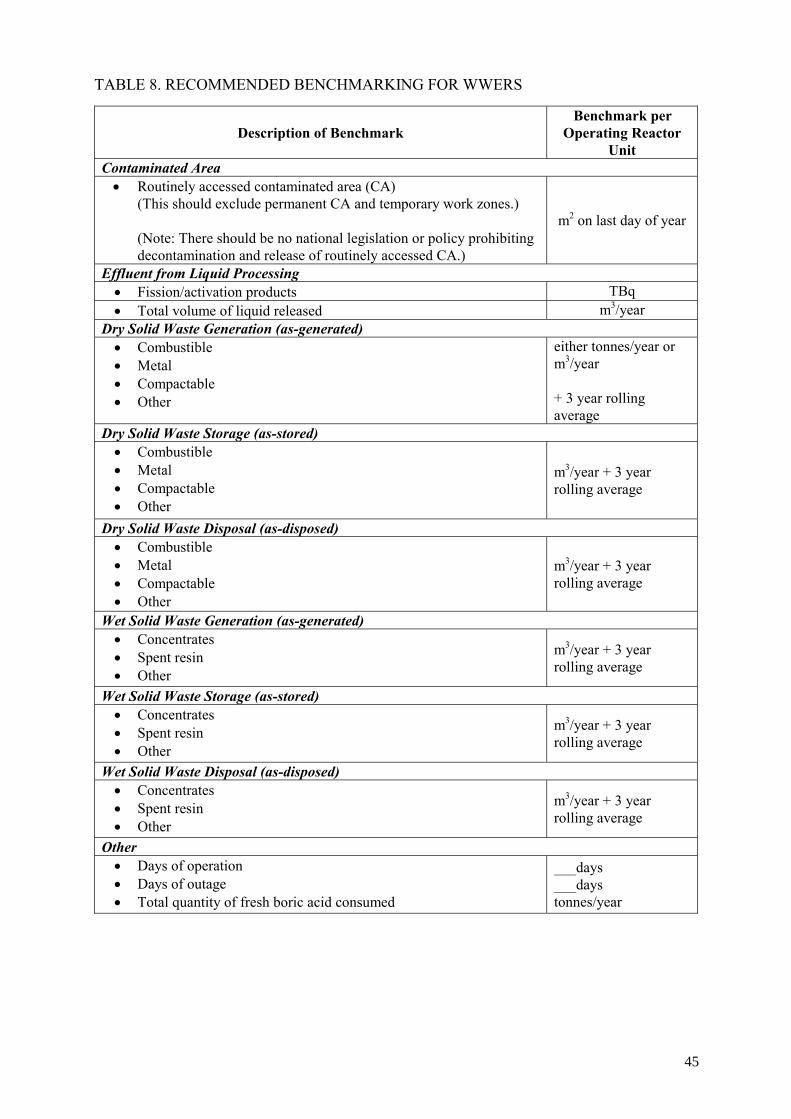
TABLE 8. RECOMMENDED BENCHMARKING FOR WWERS
Description of Benchmark
Benchmark per Operating Reactor
Unit Contaminated Area • Routinely accessed contaminated area (CA)
(This should exclude permanent CA and temporary work zones.) (Note: There should be no national legislation or policy prohibiting decontamination and release of routinely accessed CA.)
m2 on last day of year
Effluent from Liquid Processing • Fission/activation products TBq • Total volume of liquid released m3/year
Dry Solid Waste Generation (as-generated) • Combustible • Metal • Compactable • Other
either tonnes/year or m3/year + 3 year rolling average
Dry Solid Waste Storage (as-stored) • Combustible • Metal • Compactable • Other
m3/year + 3 year rolling average
Dry Solid Waste Disposal (as-disposed) • Combustible • Metal • Compactable • Other
m3/year + 3 year rolling average
Wet Solid Waste Generation (as-generated) • Concentrates • Spent resin • Other
m3/year + 3 year rolling average
Wet Solid Waste Storage (as-stored) • Concentrates • Spent resin • Other
m3/year + 3 year rolling average
Wet Solid Waste Disposal (as-disposed) • Concentrates • Spent resin • Other
m3/year + 3 year rolling average
Other • Days of operation • Days of outage • Total quantity of fresh boric acid consumed
___days ___days tonnes/year
45

It also must be recognized that the high cost of constructing and operating advanced volume reduction and conditioning technologies must be off set by a return on investment over a certain minimal waste input. For example, a country with only a few WWERs does not generate enough spent resin to meet the input demands of an expensive steam reforming facility. In such cases, international cooperatives could provide attractive alternatives to maximize the use and benefit of such advanced technologies.
a. Supercompactors for dry solid wastes—Replacing or augmenting existing low-force
compactors with higher force “supercompaction” technology will typically result in a significant improvement in volume reduction. However, this is an expensive technology which should be considered only when sufficient quantities of non-metal dry solid wastes are available as input to the supercompactor. WWERs should consider implementing supercompaction for multiple stations with large inputs, for centralized national or international volume reduction and conditioning facilities, or as mobile applications. The following guidelines apply: • High-force supercompactor (VR=7:1)—Use for >1500 m3/year • Medium-force supercompactors (VR=5:1 to 6:1) —Use for >500 m3/year • Mobile supercompaction is also an option for multi-year accumulation.
b. Incineration (VR 50:1)—This is an expensive technology which should be considered only when sufficient quantities of combustible wastes are available as input to the incinerator. Note that incineration can be used for combustible dry solid wastes, for low activity spent resin and non-metal filter cartridges, and for oil. WWERs should consider implementing incineration for multiple stations with large inputs or for centralized national or international volume reduction and conditioning facilities. In general, incineration is cost effective when the input volume approaches or exceeds 5000 m3/year.
c. Glassification for shredded dry solid waste (VR 50:1)—This is a fairly simple and
reasonably inexpensive technology (e.g., less than one-tenth the cost of a full-service incinerator). However, it requires a significant volume of non-metal dry solid waste on the order of 500 m3/year to make it cost efficient. This tends to limit its application to centralized national or international waste volume reduction and conditioning facilities.
d. Solidification of wet solid wastes (e.g., bitumenization, cementation)—Sufficient input
exists to implement solidification technology at all WWERs, either on an installed equipment basis or on a mobile technology basis. This may be applied to concentrates, spent ion exchange resin, and filters.
e. Filter shear (VR 4:1)— When the volume of spent cartridge filter waste will exceed an
average of 1 m3/year, filter shears become a very cost efficient technology (low cost, high VR efficiency).
f. Liquid Waste Treatment Technology for concentrates (VR >70:1)—This is the waste
minimization approach and technology developed by the Paks WWER and which is described in Appendix C. This is a very expensive, multi-step technology, although it has a very high volume reduction efficiency. It can be implemented at any individual WWER.
46
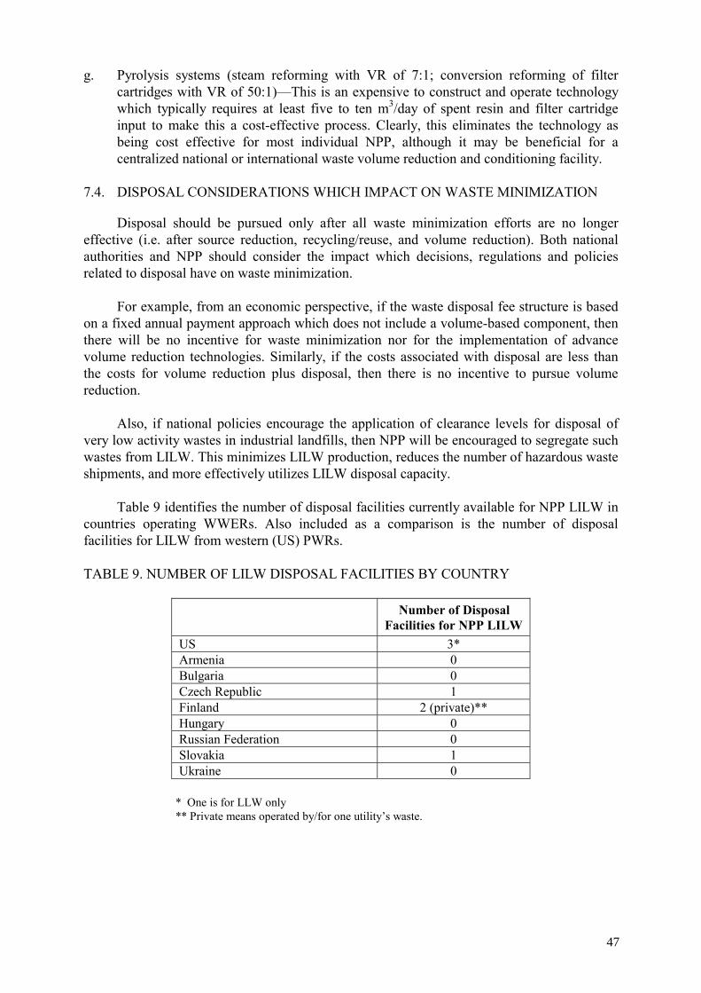
g. Pyrolysis systems (steam reforming with VR of 7:1; conversion reforming of filter cartridges with VR of 50:1)—This is an expensive to construct and operate technology which typically requires at least five to ten m3/day of spent resin and filter cartridge input to make this a cost-effective process. Clearly, this eliminates the technology as being cost effective for most individual NPP, although it may be beneficial for a centralized national or international waste volume reduction and conditioning facility.
7.4. DISPOSAL CONSIDERATIONS WHICH IMPACT ON WASTE MINIMIZATION
Disposal should be pursued only after all waste minimization efforts are no longer effective (i.e. after source reduction, recycling/reuse, and volume reduction). Both national authorities and NPP should consider the impact which decisions, regulations and policies related to disposal have on waste minimization.
For example, from an economic perspective, if the waste disposal fee structure is based on a fixed annual payment approach which does not include a volume-based component, then there will be no incentive for waste minimization nor for the implementation of advance volume reduction technologies. Similarly, if the costs associated with disposal are less than the costs for volume reduction plus disposal, then there is no incentive to pursue volume reduction.
Also, if national policies encourage the application of clearance levels for disposal of
very low activity wastes in industrial landfills, then NPP will be encouraged to segregate such wastes from LILW. This minimizes LILW production, reduces the number of hazardous waste shipments, and more effectively utilizes LILW disposal capacity.
Table 9 identifies the number of disposal facilities currently available for NPP LILW in
countries operating WWERs. Also included as a comparison is the number of disposal facilities for LILW from western (US) PWRs. TABLE 9. NUMBER OF LILW DISPOSAL FACILITIES BY COUNTRY
Number of Disposal Facilities for NPP LILW
US 3* Armenia 0 Bulgaria 0 Czech Republic 1 Finland 2 (private)** Hungary 0 Russian Federation 0 Slovakia 1 Ukraine 0
* One is for LLW only ** Private means operated by/for one utility’s waste.
47

7.4.1. Actions by national authorities and NPP which relate to waste disposal and which encourage waste minimization
7.4.1.1. Minimum standards a. Avoid implementing a fixed annual disposal fee structure which does not include a
volume-based component. A volume-based disposal fee structure encourages waste minimization; a fixed annual fee structure discourages waste minimization. An alternative to the fixed annual fee structure includes a combination of fixed-plus-volume-based fees. This is addressed in further detail at the beginning of this section under the discussion on waste minimization motivators.
b. National authorities should implement a policy which encourages the maximum
segregation of clean waste from radioactive waste for disposal in an industrial landfill. This policy can be further encouraged by ensuring that a significantly higher disposal fee is applied to LLW than for clean waste. The intent is to minimize the quantity of clean waste which would otherwise be shipped to LLW disposal sites, thereby extending the life of the disposal facility. It also reduces the volume of waste which is placarded for shipment as radioactive waste.
c. Implement (as opposed to simply establishing) clearance levels which reduce LLW
disposal volumes. Also avoid requiring case-by-case approval for each waste shipment which is below a country-specified clearance level. This reduces disposal costs, makes more effective use of storage capacity, extends the life of the LILW disposal facility, and reduces the number of radioactive waste shipments.
d. Specify maximum “void-space” allowed in disposed waste packages “Void space”
refers to the empty air space between the top of the waste and the lid of the waste container. Typically, this void space should not exceed 15% of the internal volume of the container. The intent is to maximize the amount of waste in every package, thereby reducing the impact on storage, reducing the number of waste shipments, and extending the life of the LILW disposal facility.
7.4.1.2. Recommendations and good practices related to waste disposal
a. Activity-based disposal surcharges promote “hold-for-delay” strategies. Consider using
activity surcharges to encourage temporary storage of waste packages for up to one year to allow the decay of short-lived nuclides. This approach typically reduces total activity for most high activity waste packages by at least half, thereby reducing the radiation exposure during shipment and during handling at disposal facilities. It also reduces the potential risk of release in the event of a terrorist incident during transport. (Note: it is recognized that most WWERs are experiencing significant stored waste volumes which, by default, automatically implements this decay strategy.)
b. Countries which are planning or constructing their first NPP should consider early siting
and development of a LILW disposal repository. Even if this is not possible, early development of waste acceptance criteria should be pursued. The primary intent is to promote waste minimization by early specification of waste packages and waste form. This will also:
48

• Reduce the need for repackaging stored wastes. • Reduce radiation exposures from multiple handling and repackaging of stored
wastes. • Reduce or eliminate the cost of constructing storage facilities.
c. Consider implementing clearance protocols for bulk quantities of clean and, possibly,
very low (at or below clearance levels) [3] activity wastes. An example would be to allow averaging activity concentrations over an entire drum of waste as opposed to requiring detailed analysis of every piece of waste.
d. Consider the use of hazardous waste landfills for disposal of “very low activity wastes”
which contain slightly more than exempt quantities of activity (slightly more than the clearance levels discussed in References 3-4). For example, a landfill for toxic waste might be authorized to accept waste up to 0.1 mSv/h of short half-life materials (e.g., <35 year half-life), thereby recognizing that the small quantity of activity will decay to a stable state long before the toxic waste component ceases to be of concern. The intent is to maximize the use of hazardous waste landfills through the inclusion of low radioactivity (and low radiotoxicity) wastes, thereby promoting more effective use of LILW repositories.
e. Evaluate any existing waste form restrictions with the intent of improving flexibility for
those with higher packaging efficiencies. For example, low activity spent resin can be more efficiently packaged if dewatered than if solidified. Higher packaging efficiencies provide more effective utilization of disposal capacity and reduce the number of waste shipments.
f. Waste minimization, including volume reduction, also reduces the number of hazardous
shipments. In addition to transportation cost savings, this has the additional benefit of reducing risks from terrorism.
49

8. CONCLUSIONS
Improvement in waste minimization is an evolutionary process. The degree of waste
minimization evolution among all WWERs varies from “little serious effort” to “reasonably advanced.” At the present time, the majority of WWERs are at the lower end of the waste minimization performance scale; even the more advanced WWERs remain behind western PWRs in terms of waste minimization and may need to adapt and implement more advanced, higher efficiency technologies in the future. The following paragraphs illustrate current situation at WWERs and PWRs with primary contributors to existing gap in waste management systems performance:
— WWERs generate more than ten times the quantity of wet solid waste as comparably
sized western PWRs. In general, this difference between WWERs and PWRs is not due to technical limitations. It is more directly linked to plant operating practices, legal restrictions, and funding limitations. Since western (US) PWRs are either owned by private companies or are operated as commercial enterprises, they are very competitive and are, therefore, far more aggressive than WWERs in enforcing source reduction programmes, implementing aggressive recycling and reuse programmes, and pursuing competitive waste conditioning and disposal technologies.
— In contrast to wet solid waste, WWERs and western PWRs generate comparable
quantities of dry solid waste. — Western PWRs have implemented numerous highly advanced volume reduction and
conditioning technologies for use in centralized facilities, which are very expensive to purchase and operate. Individual NPP or utilities rarely own such technologies. High efficiency technologies are generally expensive and require a very large volume of waste input to be cost effective. There are more than 100 US NPP, which feed these highly advanced technologies. The absence of centralized processing facilities for WWERs limits the input volume of wastes so as to make large investments in advanced technologies cost prohibitive.
— It is a common misconception that the greater overall volume reduction efficiency of
western PWRs is due to waste management techniques or to technological capabilities not known to WWERs. More accurately, there are mainly political, legislative, environmental, economic, and commercial realities, which account for almost all of the WWER constraints when compared to western PWR waste minimization programmes.
— Since most WWERs were historically operated under the control of noncompetitive
government agencies, there are insufficient motivating factors either at the national level or at the local plant level to pursue cutting edge of highly efficient (and often very expensive) volume reduction and conditioning technologies. Aside from a few exceptional plants, it is likely that the majority of WWER plants will continue to dispose of larger wet and dry solid waste volumes than western PWRs unless a change in certain key factors discussed in Section 7 initiates an industry-wide, focused priority and effort toward implementing and sustaining more aggressive waste minimization programmes.
50

— The amount of waste accumulated in WWER storage facilities is now one of the principal factors promoting waste conditioning technologies. This suggests a reactive response rather than a planned initiative. In addition, the anticipated decommissioning of some plants and the expected large quantities of processible waste may economically stimulate this process either on a national basis or as part of a multi-national effort. However, this will require both legislative and economic incentives. Based on the discussion in Section 6, it is possible to track the evolution of western
PWR waste minimization progress over the past 20 years. The information is relevant to this report as it offers suggestions for initiating and realizing dramatic improvements in WWER waste minimization programmes through the implementation of fairly inexpensive measures. This approach requires a combined effort from regulators and plant operators in following areas:
— to give a high priority to implementing and sustaining industry-wide minimum
performance standards for waste minimization programmes at both national and utility levels at all WWERs, which will promote measurable progress and a process of continuous improvement at every WWER (these efforts are detailed in Section 7, and they serve as the cornerstone of this report),
— to implement of the minimum performance standards serving as a road map defining the path forward for regulators and plant operators of WWERs (additional recommendations are also included in Section 5, but they are considered as being of a much lower priority than the pursuit and implementation of the minimum standards of performance on an industry-wide basis),
— to establish peer communication to promote waste minimization practices, especially to use benchmarking to track key waste-related performance data. (Section 7 includes a table of benchmarking parameters which should be pursued by all WWERs and which are, for the most part, already being benchmarked for western PWRs),
— to implement disposal policies and fee structures which will create an environment encouraging waste minimization strategies. Most notably, fixed annual disposal fee structures, which do not include a volume-based cost component, generally discourage waste minimization efforts, and they discourage implementation of advanced volume reduction technologies. (Section 7 includes specific recommendations for motivating waste minimization at the national and NPP level, including minimum standards and good practices applicable to disposal and which also encourage waste minimization). In summary, numerous opportunities exist for making substantial improvements in the
waste minimization programmes of WWERs, thereby reducing waste storage and disposal volumes and reducing life cycle operating and decommissioning costs. There will always be individual plants and nations which use information such as is provided in this report to excel beyond their peers. However, initiating an incremental change for the entire fleet of seventy WWERs—which is the desired objective of this report—will require an industry-wide effort at both the regulatory and plant operating levels.
51


Appendix A
MOST COMMONLY USED WASTE VOLUME REDUCTION AND CONDITIONING TECHNOLOGIES FOR WWER AND PWR PLANTS
Depending on the local waste management strategy and locally available volume reduction and conditioning technologies, NPP operational wastes are subdivided into descriptive waste types that can be associated with specific volume reduction and conditioning technologies. The most common waste types are identified in Table 10. The table also identifies the typical proportion for each of the as-generated waste types according to the entire generic waste category (dry solids, wet solids), as well as identifying the technologies most commonly used for treating and conditioning each waste type. Typical volume reduction ratios are provided in the legend which follows Table 10.
TABLE 10. SUMMARY OF AS-GENERATED NPP OPERATIONAL WASTE TYPES AND IDENTIFICATION OF VR AND CONDITIONING TECHNOLOGIES
Source and Waste Type
Typical As-Generated
% Composition
Conditioning Technologies
Most Common Conditioning Technology
Dry Solid Wastes (Intermediate Activity)
Core Components > 99 A,N,Q N Dry Solid Wastes (Low Activity & EW)
Clean (EW) 20 – 80 K K Combustible 40 - 80 A,B,C,D,F B Compactable Noncombustible 20 - 60 A,C,D,X,W D Metals 5 - 30 A,D,G,H,W,X G,H Wood 0 – 15 A,B,D,L L,B Fuel Racks < 1 A,D,G,H,N H,G Thermal Insulation < 3 A,C,D D Air Filters < 3 A,B,C,D,G,X D Charcoal < 3 A,B,D,J,X J Concrete < 1 A,D,I,J A,J Rubble < 1 A,D,I,J J,D Soil < 1 A,I,J J Grit Blast Media < 1 A,D,J,X J Oil absorbents < 1 A,B,C,D,J B Other < 1
Wet Solid Wastes (Low & Intermediate Activity)
Concentrates 0 – 80 Q,S,X,Y,Z X,S Filters 0 – 25 D,O,Q,R,T,X T,D Slurries < 10 P,S,T P,T Sludges < 10 P,S,T,X,Z S,T,Z Spent Resins 0 – 80 B,F,M,O,P,T,X,Y
,Z O,T,Y,X
Treated Oils/Solvents < 1 A,B,E B
53

Conditioning Technologies Legend for LILW: Conditioning Technology Typical VR Ratio
A. Direct disposal without conditioning 1:1 to 1:2* B. Incineration/combustion 95:1 to 100:1 C. Compaction 2:1 to 6:1 D. Supercompaction 4:1 to 10:1 E. Clay immobilization 1:3* F. Glassification 20:1 to 50:1 G. Metal melt 20:1 See Note 1 H. Decontamination/salvage 7:1 I. Decontamination/EW 7:1 J. Use as overfill See Note 2 K. Survey/clean release See Note 3 L. Wood planing/salvage 4:1 to 20:1 M. Wet oxidation 7:1 N. Cut & condense package 3:1 to 30:1 O. Steam reforming or catalytic extraction 7:1 See Note 4 P. Drying of sludges/slurries/resins 2:1 to 5:1 Q. Encapsulate 1:4* R. Shred 1:1.5* S. In-container evaporation 3:2 to 10:1 T. Dewater into HIC 1:1.2* V. Deep evaporation 99:1 W. Molten metal 3:1 to 5:1 X. Cementation 1:2* Y. Bitumenization 1:1.5* Z. Polymer solidification 1:2*
* Volume is increased during conditioning or packaging VR is calculated as follows: Note 1: If metal waste is recycled, such as through conversion to waste containers or shield blocks during the
melting process, then the net volume reduction approaches 1000:1, with only the slag being packaged and disposed as radioactive waste.
Note 2: Soil, grit media and similar materials are commonly used to fill void spaces in waste packages. Since disposal volumes are usually based on the external dimension of the waste package, using soil, grit, etc. to fill void spaces (overfill) within a waste package effectively eliminates the soil/grit as an independent waste volume.
Note 3: Potentially clean materials and exempt wastes at or below clearance levels that are segregated from LILW are subjected to some type of process, such as radiological survey or process knowledge, to verify that it can be released as exempt. If the segregation process at the point of generation is inefficient, then some percentage of the waste will have to be redirected into the LILW stream. However, if the segregation process is highly effective, then the potential exists that all of the segregated clean and exempt materials can be released as exempt. [3-4 ]
Note 4: Steam reforming of nonmetal filter cartridges—also referred to as tank conversion reforming—
demonstrated an average VR of 35:1 in field trials in the US.
VorigVR =
Vafter
54
1. UNUSUAL TERMS AND UNCOMMON CONDITIONING TECHNOLOGIES A detailed discussion of waste types and common waste processing technologies is
beyond the scope of this report. Such information is addressed comprehensively in other IAEA publications [References 2, 9, and 30–33 for liquid and wet solid wastes; References 13, 31, and 34–35 for dry solid wastes]. However, Table 10 includes some waste types and conditioning technologies which may not be immediately recognizable by the otherwise informed waste management professional. Those are addressed as follows:
— High Integrity Container (HIC): A container that is designed to contain disposed waste
for 300 years or more;
— Sludge (wet particulate solids): The most common example of sludge is the wet particulate material which settles to the bottom of a water collection tank. Once removed from the tank and dewatered, the remaining wet solid waste (particulate) is referred to as sludge.
— Slurry: A combination of particulate solids (e.g. resins, filtration materials, or sludge which is re-suspended in liquid) and liquid media that is capable of being moved through a piping system (e.g. between tanks or from a tank to a waste disposal liner). Note: Wet sludge and resin do not move through piping systems easily unless they have a low solids content. Typically, a flowable slurry (one that is capable of moving easily through piping systems) will have a solids content of less than 5-10%. At >25%, there is a high probability of blockages occurring within the piping system.
— Resin dewatering: This refers to the removal of interstitial water, usually by gravity or pumping (as distinguished from drying). As the term applies to the processing of spent resin, there are two similar but distinctively different meanings:
(1) When solidifying spent resin, the resin can be dewatered to obtain the desired resin:water:binder ratio. It is not intended that all free-standing water be removed from the resin before addition of the binder. In this case, the dewatering effort is a subcomponent (preliminary step) of the solidification process.
(2) When dewatering resin for disposal without the intent of solidification, the dewatering pump and system continues to draw water from the resin until there is no free-standing liquid.
— Glassification: Glassification is, essentially, vitrification, as the final waste residue is combined with the glass vit. This is very similar to cold crucible vitrification, aside from the technical design and approach for melting of waste. However, it is considered as a separate volume reduction and conditioning technology when applied to non-metal dry solid wastes due to the open feed design and inexpensive equipment. The glassification process competes directly against incineration for many combustible materials. The process initially involves heating a pool of glass in a reaction chamber to approximately 1000 to 1500oC using external heat (e.g., propane or electric heaters) and then maintained at temperature using electric heaters. Once the glass achieves a molten mass, waste and combustion air are added to the top of the reaction chamber. The combination of radiant heat and direct contact with the molten glass produces combustion and releases the exhaust gases through a monitored pathway. The solid end products are submerged in the molten glass (either dissolved or encapsulated) and are usually
55

removed periodically by scooping the encapsulated material out of the glass pool. This vitrified waste is then allowed to cool into a nonleachable, stabilized final waste form.
— Steam reforming/pyrolysis: This process relies on super-heated steam to reform or reduce waste (in particular spent ion exchange resins) to small gas size particles which can then be burned in a special reactor devoid of oxygen. Thus, it is a two-stage process in which hydrocarbons are vaporized from the waste in one chamber and injected into a reaction chamber with superheated steam where organics are converted to CO2, CO and H2. The remaining waste product consists primarily of the metal oxides and other inorganic impurities removed from the waste generator’s in-plant coolant and liquid waste systems. The resultant waste form appears as a dry granular media which can be disposed in liners or high integrity containers. Since steam reforming does not employ combustion in an oxygen atmosphere to reduce waste, it is not usually classified as an incineration technology, but rather as a thermal destruction technology [36].
— Rubble: Small debris waste from construction and dismantlement projects. Examples include small chunks of asphalt or concrete removed from parking areas; small chunks of concrete or cement block from dismantling a building. (Note: in some cases it may be a desirable and cost efficient dismantlement approach to knock down an entire building and then collect the rubble in the boxes for disposal. This approach is commonly referred to as “rubblization” or “reducing the building to rubble.”).
— Grit Blast Media: This refers to the media used in grit blasting. Grit blasting is one of several decontamination processes which propel some type of granular media at a target to blast rust, paint or contaminants from the surface. Examples of common grit blast media include sand, aluminum oxide, zirconium oxide, steel shot, glass beads, and plastic beads, each of which has a different combination of removal efficiency and abrasiveness (surface degradation).
— Wood Planing: The primary objective of wood cutting and planing is to segregate contaminated portions of the wood from the clean portions. The clean portions are directed into a monitoring/discharge process, and the remaining contaminated portions are subjected to other waste processing technologies (e.g., incineration, compaction, overfill). Accordingly, wood cutting and planing is considered as a treatment step followed by final conditioning. Most contaminated wood retains the contaminants within 6 mm of the outer wood surface, and it typically concentrates at the ends of wood planks. Wood cutting is commonly used to cut the ends off wood planks, allowing the remaining material to be directed into a monitoring/release program. For wood planks which are contaminated over a large percentage of the surface area, planing using a wood planer is an effective means of separating the contaminated surface materials from the remaining clean materials.
— Molten Metal: Molten metal is relatively new and widely used throughout Japan, but it has not yet made significant inroads into other countries. The origin of this technology is in the steel industry; dry active wastes (metal, concrete etc.) are combined in a ceramic canister and melted by high frequency induction. The melting temperature is about 1500°C. The final waste form is a stabilized ingot. (Note: This differs from metal melt in that it combines multiple waste streams with at least 10% metal composition, and not just metallic waste.) [37].
56

Appendix B
RADIOACTIVE WASTE MANAGEMENT AT LOVIISA NUCLEAR POWER PLANT
1. PLANT DESIGN CONSIDERATIONS IMPACTING WASTE MANAGEMENT
There are two WWER-440 units at the Loviisa NPP. Loviisa 1 started in 1977 and
Loviisa 2 in 1981. Fuel cycle is 12 months [8]. There is a large liquid waste storage at site: 4 tanks each 300 m3 for spent ion exchange resins and 4 tanks each 300 m3 for concentrates. During the 1990s the electrical power of the Loviisa NPP has been increased to a nominal output of 2x 488 MW(e) (net), and the life time has been extended (from the original of 30 years) to 50 years in 2003. Solidification plant (based on cement) is nearing completion of construction and is anticipated to be operational in 2006.
2. PLANT LOCATION AND ENVIRONMENTAL CONSIDERATIONS
The Loviisa NPP is situating on coast of a sea (the Gulf of Finland) and some liquid
discharges (borates, nitrates etc.) are allowed to sea.
3. SOURCE REDUCTION APPROACHES There are some source reduction approaches at the Loviisa NPP:
— cobalt content of the stainless steel pipes etc. has been restricted to max. 0,05% — boric acid recovery system for primary circuit water (primary coolant) is used — evaporated and ion exchanged drain waters can be used as make-up water. Ion
exchanged pool waters and steam generator blow-down waters can be reused. — normally it is prohibited to take any packages into the controlled area. Disposable
insulating wool has been partly replaced by reusable material. A slight contamination level in the scaffolding material is accepted.
The average volumes of wastes collected during the last years have been the following:
— spent ion exchange resins 12 m3/a — evaporator concentrates 70 m3/a — dry solid materials 100 m3/a.
4. PLANT DESIGN UPGRADES TO IMPROVE WASTE MANAGEMENT
There are some special plant design upgrades for waste management at the Loviisa NPP
— dry solid waste generated during the operational and maintenance activities is segregated based on material type of the waste and dose rate of the waste. The compactable and non-compactable wastes as well as burnable and non-burnable wastes are segregated. Volume reduction of compactable waste by use of low force compactor followed by packing into 200 liter steel drums is done in both units of the Loviisa NPP
— re-routing of primary sampling waste to boron recovery system was carried out and this allows these solutions to be recycled
57

— drain water evaporation system was modified in 1986 to reach a salt content 350 g/liter in the concentrates. A pump was installed between the main evaporator and the additional evaporator and a new return pipeline back to drain water tanks was installed. Annual collection of evaporator concentrates was reduced by 50 %.
— cesium removal system for evaporator concentrates was taken into use in 1991. Old concentrates in huge liquid waste storage are containing mainly Cs-137 and Co-60 radionuclides. Co-60 is associated with the solid precipitates on the tank bottom. By removing cesium from the tank solution, the purified liquid can be released within licensed release limits. Cesium removal is based on developed (by the company Fortum and the Radiochemistry Laboratory of the University of Helsinki) ion-specific filters using cesium selective inorganic ion exchange material, CsTreat, in granular form in stainless steel columns. By the end of the year 2002 totally 14 pieces of 8-liter columns were used and 219 GBq of cesium were removed, and more than 900 m3 of purified concentrates had been released into the Gulf of Finland.
— low- and intermediate level operating waste is disposed of in a repository constructed in the bedrock of the power plant site at the depth of about 110 meters. The repository (total volume about 110 000 m3) was put into use as a final disposal facility in 1999. By the end of 2003, more than 5000 steel drums (each 200 liters) of maintenance waste were disposed.
— a solidification plant (based on cementation and using of concrete containers, height and diameter 1,3 m, outer volume 1,7 m3, as final disposal packages) is under construction. The construction work began in 2004, and the commissioning of the plant will be in 2006.
5. WASTE CONTAINERS AND PACKAGES USED FOR STORAGE AND DISPOSAL
There are until now only two types of containers (packages) used for storage and
disposal at the Loviisa NPP:
— 200 liter steel drums for maintenance waste. More than 5000 drums have been already disposed of into the repository.
— 1 m3 concrete containers (height and diameter 1,3 m, outer volume 1,7 m3) for spent cesium removal columns. Container has 12 disposal holes in the concrete filling for 12 pieces of cesium removal columns. Only two containers are collected until now.
58

Appendix C
RADIOACTIVE WASTE MANAGEMENT AT PAKS NUCLEAR POWER PLANT
1. PLANT DESIGN CONSIDERATIONS IMPACTING WASTE MANAGEMENT
Paks NPP comprises four WWER-440 nuclear reactors, each with a capacity of 460
MW(e) [14]. The four reactors were commissioned in 1983, 1984, 1986 and 1987, respectively. This plant regularly produces almost 40% of the electricity consumed in Hungary, although it represents only about 25 % of the total installed capacity. The units run with 12 months fuel cycle.
The plant was built with 7328 m3 storage capacity for liquid radioactive waste and spent
resins with the policy of collection of all liquid waste into this storage facility comprising of separate tanks for evaporator concentrates (5205 m3) and spent resins (2123 m3). The accumulated waste was to be solidified before finally being disposed of. Extension of the liquid waste storage tanks as needs arises. The storage capacity for wet solid waste is 7200 drums (with 200 l of volume).
2. PLANT LOCATION AND ENVIRONMENTAL CONSIDERATIONS
In Hungary, nuclear power provides a substantial portion of the total electricity
produced in the country. The only one nuclear power plant in Hungary is situated at the bank of river Danube, that supplies the cooling water for operation. The level of suspended solid and other contaminants depends on season and means different load on make-up water plant. Strict environmental limits are pending for releases into the river.
3. SPECIAL SOURCE REDUCTION APPROACHES
As a special source reduction approach the cleaning and recirculation of contaminated
boric acid by ultra filtration is applied (in addition to those common approaches mentioned in Appendix B by Loviisa Plant). Clean boric acid solutions generally become contaminated during their use and storage in different systems. A part of these impurities can be removed by built-in mechanical and ion exchange filters but micron and submicron sized non ionic contaminants can accumulate during years since when not having the appropriate cleaning system for their removal. The effective removal of these impurities is an important requirement but can not be carried out by usual techniques. Ultra filtration method has been chosen from possible solutions taking into consideration different aspects. The products of this separation method are always two liquid streams:
— filtrate, that passes through the membrane. — concentrate, that remains on the feeding side of the membrane.
The experimental cleaning of contaminated boric acid solutions by ultra filtration
method began in 1991 and 1992, under real conditions, with several hundreds litres/hour capacity equipment, using the newest Hungarian made polysulphone spiral modules. The equipment was built into a bypass line of an existing ion-exchange filter area so the system is also suitable for filtration the primary coolant.
59

Based on experiment, both the non radioactive impurities and radionuclides (54Mn, 58Co, 60Co, 110mAg) bound to colloidal particles could be removed with 100 % efficiency.
This experiment was followed by process optimization. Cleaning boric acid solution
with various contamination, setting up different filtrate/concentrate ratios, the best efficiency could be reached with a special polysulphone membrane when the solution to be cleaned was evaporated before fed to this process, up to 40 g/l boric acid concentration (which can be carried out using the existing evaporator system). Based on the good experience acquired, two lines of a 25 m3/h capacity ultra filtration unit has been implemented that can purify all the contaminated boric acid solution stored in the controlled area and primary coolant during start-up and shut-down operations.
Up to now some 5000 m3 of contaminated boric acid solution has been purified by
ultrafiltration, decreasing the volume of liquid radioactive waste. The quantity of radioactive waste produced in 2002 at Paks NPP was the following (for
all the 4 units):
— concentrates 260 m3 — resins 2,5 m3 — solids 660 drums (of 200 l volume): 403 drums compacted
199 drums non-compacted 58 drums sludge
4. PLANT DESIGN UPGRADES TO IMPROVE WASTE MANAGEMENT Having refused the Russian concept - waste disposal at the plant side -, the Hungarian
operator has made a lot of changes in the original design to reduce the volume of the radioactive waste and enhance the efficiency of the waste treatment system.
Treatment of solid and wet waste is mainly based on the following activities:
— Segregated collection of solid waste generated during the operational and maintenance activities. Segregated collection is based on the material type of the waste and dose rate of the waste package. The compactable and non-compatible wastes are segregated. A sorting box has been installed with an aim to segregate the non or slightly contaminated – subject to clearance – waste from the radioactive waste.
— Packaging of the non-compactable waste into steel drum. — Volume reduction of compactable waste by use of compactor of medium pressing force
(50 t) followed by packaging into 200 litre steel drums; — Interim storage of drummed waste in the auxiliary building. — Sludge generated during the maintenance of various heat exchangers and tanks are
segregated and collected into steel drums where it is mixed with sorbent material (diatomaceous earth) for bounding of the water content of sludge. Special storage wells located in the reactor halls serve for storage of higher level of dry
active waste (e.g. neutron detectors, control rod drives, activated test specimens) Expiration of liquid waste storage tank capacities, delay of the final repository project
and the expected high costs of final disposal has led to exploration of new solutions.
60

The main criteria of the necessary waste treatment technology were laid down by the experts of Paks NPP. These criteria are as follows:
— Recovery of boric acid in reusable form from the concentrates stored in tanks. Selective
separation of radionuclides from the waste with as high decontamination factor and volume reduction ratio as achievable.
— Decontamination and purification of boron containing waste. — Decomposition of Fe(II)-EDTA complex containing radioactive liquid waste.
4.1. System description and operating principles.
An evolution of the Loviisa NURES system is currently being implemented at Paks
NPP. For the application of Paks NPP, the original NURES-technology has for the first time been complemented with removal of corrosion products and a Boron Recovery System.
The new system consists of three subsystems:
— Boron Recovery System (BRS). — Ultra filtration System (UFS) — Cesium Removal System (CRS) and tanks, pumps, valves and other necessary
equipment. The new system is located in the auxiliary building. The Boron Removal System (BRS) is used for separation of boron from evaporator
concentrates for reuse. Boron will be separated into a solid alkaline borate cake, interim-stored, and it can be reused as boron feed.
For crystallisation of alkaline borate pH is adjusted under controlled conditions in a
separate tank. Separation of alkaline borate is carried out by a highly efficient pressure filtration unit, recovering a relatively dry and clean cake of alkaline borate. The capacity of the pressure filtration unit is 1 m3/h of liquid.
At least 70 % (wt) of boric acid content of the original waste can be recovered in a
reusable form and quality in solid form. Filtrate will include some 20 g/l of boron and it is taken for further treatment. After the boron recovery the liquid is led to the Nuclide Removal System.
The Ultra Filtration System (UFS) is used for removal of particulate material from
liquids. The principle of operation includes separation of liquid with ionic material with a large volume from small volume with concentrated particulate material. The system is automatically controlled. Automation and activity measurements are common for the combination of the UFS and cesium removal system. The liquid is purified in this system and collected to be released.
Decontamination factor (DF) for nuclides Mn, Co, Nb, Zr and Ag altogether as an
average is higher than 100, giving that less than 1 % of particle bound activities will be in purified liquid. Maximum flow rate in purification to reach this DF is 240 l/h.
The Cesium Removal System (CRS) is foreseen for removal of isotopes 134 Cs and
137Cs. The Cesium removal is combined with the Ultra filtration system to form a larger Nuclide Removal System. Their capacities have been adjusted to match each other.
61

The capacity of the system is up to 240 l/h with two parallel ion exchange columns. The Decontamination factor (DF) for cesium is better than 1000 when DF factor is calculated as the ratio of cesium concentration in the input of the cesium removal system to cesium concentration in the output of the system.
The system operates with automatic control. The automation and electric supply system
are common for the Ultra filtration and CRS. Adding ion exchanger units can easily increase the capacity of the system. Designed volume reduction factor will be about 8000.
As auxiliary materials the CRS needs only acid for pH control, if pH control is needed.
Otherwise the liquid is led directly to the CRS. Purified liquid goes to the storage tank and from there to the control tank for release via exiting release routes.
Cobalt removal system is also a new element of the modified Finnish technology. As
the cobalt forms complex, a special device is being designed for decomposition of these complexes.
4.2. Secondary waste management
The secondary waste generated consists of spent ion exchange columns, of sludge from
ultra filtration system and of spent filter cartridges. All secondary waste is suitable for simple conditioning for disposal. A reinforced concrete container is foreseen for interim storage and final disposal of spent ion exchange columns.
Spent filter cartridges and materials are foreseen to be disposed of in standard 200 litre
drums. The secondary waste arising is dominated by the sludge generated by the Ultra filtration
system. The design value for waste to be disposed of depends on the properties of the liquid to be treated. The designed overall volume reduction factor for evaporator concentrates is in the range of 40 to 90.
Until today some 4,000 m3 of evaporator concentrates have been generated at Paks NPP.
Solidification of such an amount with cement would result to more than 10,000 m3 of conditioned waste. Considering the above volume reduction factors the amount of waste to be disposed of is likely to be less than 300 m3.
4.3. Underwater plasma technology
During the treatment of radioactive aqueous liquid wastes one of the most commonly
encountered problems is how to get rid of the organic content that is responsible for keeping most of the radionuclides in solution by forming water soluble complex compounds with them.
In the course of the steam generator cleaning performed at Paks NPP radioactive
solution waste containing Fe-EDTA was generated in 1998 and 2000. For the decrease of its EDTA concentration a new technology was developed by the Hungarian G.I.C Ltd. which is capable of decomposing practically any kind of organic materials contained by the radioactive waste.
62

As the result of the treatment the original EDTA quantity is decomposed with at least 96.5% conversion. During the decomposition carbon dioxide (sodium carbonate), water, nitrogen, iron-hydroxide and a solution with low organic matter content (residual EDTA) generate. Quantity of inorganic compounds (boric acid, inorganic radionuclide salts etc.) does not change during the treatment.
The introduced technology is basically a whole new type of “incineration” method. It
takes place even in very dilute, organic material containing aqueous waste solutions, and is capable of decomposing the organic content without having to evaporate the water. Hence it can be successfully applied for the treatment of different organic containing industrial liquid wastes.
The basics of the method is the following: in solutions of sufficient electrical
conductivity plasma zone is being formed between the surface of the submerging electrodes and the solution by the effect of either ordinary network frequency or high frequency alternating electric current of sufficient voltage, causing the organic content of the solution to undergo thermal and chemical decomposition. The decomposition takes place due to both the UV radiation and the extremely high temperature (15,000–20,000oC) of the plasma. The decomposition of the organic material can be intensified further by oxidative environment provided by adding appropriate oxidizing agent. Due to the minimum 50 Hz frequency alternating polarity electrodes electrochemical reaction can not take place.
During the operation the wastewater is kept at boiling temperature, therefore it can as
well be concentrated on demand to a required extent by means of controlled condensate withdrawal. If the waste has sufficient electrical conductivity and pH, it basically needs no solid chemicals added; therefore the solid content is not increased.
The technology has been successfully applied at Paks NPP where the EDTA content of
approximately 1,000 m3 Fe(II)-EDTA complex containing radioactive liquid waste was decomposed. The applied technology is continuous, with a capacity of 200–250 l/h. Its electric power consumption was 10–15 kWh/mol EDTA depending on the initial EDTA concentration.
The speed of processing is 150–250 dm3/h depending on the EDTA concentration of the
waste solution. The capacity can be increased by using more electrodes or by binding other reactors, as well as with increasing the efficiency of the decomposition so to operate the equipment with higher EDTA concentration.
The treated waste is 3–4 fold concentrated comparing to its original volume. Solubility
of the salts of the waste solution determines the degree of concentration. The final product was primarily examined for its EDTA content. The Fe-EDTA concentration of the residue is 2.5–4 g/dm3. Lower EDTA content than this only can be achieved by further concentration of the waste solution or very long treatment. Anyway, the above EDTA concentration is at the border of detectability of the analytical method.
The technology can also be used for the very effective destroy of complexing agent in
order to eliminate radioactive cobalt isotopes from a high boric acid containing liquid waste, originating from the primary coolant. A 200–250 l/h capacity three-unit cascade type equipment is being currently installed at Paks NPP, which is capable of lowering the overall activity of the 58Co and 60Co isotope content from a starting level of >20,000 Bq/l down to
63

around background, that is below 100 Bq/l, (based on results from pilot plant experiments carried out with the actual waste on the premises). Its electric power consumption is 6–8 kWh/l.
5. WASTE CONTAINERS AND PACKAGES USED FOR STORAGE AND DISPOSAL
Containers used for storage and disposal of all types of waste have 200 litres of volume
with plastic inside liner. Wall thickness is 1,2 mm, diameter 560 mm, height 850 mm.
64

Appendix D
RADIOACTIVE WASTE MANAGEMENT AT BOHUNICE NUCLEAR POWER PLANT
1. PLANT DESIGN CONSIDERATIONS IMPACTING WASTE MANAGEMENT
NPP Jaslovske Bohunice consists of four WWER–440 reactor units [15]. These were
constructed using a “double-unit” concept — two reactors, one common auxiliary building. The first double-unit called “V-1 plant” has older vintage V-230 type units and was commissioned in years 1978-80. The second double-unit called “V-2 plant” consists of newer V-213 type units; it was commissioned in years 1984-85. All units are operating with a 12 month fuel cycle. Both V-1 and V-2 plants have been equipped with similar waste collection, treatment and storage system so they represent two independent nuclear facilities in one site.
The following storage facilities were foreseen by the design:
— 4500 m3 for concentrates — 3000 m3 for spent resins — 4800 m3 for LLW dry solid waste
2. PLANT LOCATION AND ENVIRONMENTAL CONSIDERATIONS
NPP Jaslovské Bohunice is one of two NPPs operated in the Slovak Republic. It is
located in south-west of Slovakia, using the river Vah as a source of water for plant cooling needs as well as a recipient for liquid releases. National environmental limits significantly restrict release of boron containing compounds, in the case of NPP it is boric acid.
3. SOURCE REDUCTION APPROACHES
In 1993 the first program to identify main sources, and to reduce waste generation rate,
was launched with the following activities:
— Improvement of operational procedures especially in handling of liquids — Prompt investigation of all increased (abnormal) liquid waste flow by shift personnel — Improved maintenance of pump seals and drain valves to avoid leaks — Re-routing of primary sampling waste from sump to boron recovery system allowing
thus recycling of these solutions — Installation and preferred use of “low waste volume” decontamination technologies
(ultrasonic, high pressure water spraying, electrochemical) with recycling of decontamination solutions
— Optimization of water purification systems operation In 1999 a comprehensive Plant Waste Minimization Program was implemented into
plant QA documents where requirements similar to PWRs industry practice have been implemented. As result of these waste minimization measures, the plant total annually generated liquid radwaste volume was reduced from 600 m3 in first years of operation down to 180-200 m3 in recent three years. Average total annual volume of spent resins is 15 m3. For solid radwaste, the plant total annual generation was reduced from initial 350 m3down to 170-190 m3 in the recent years.
65

NPP Bohunice did not implement extensive recycle program, part of boric acid and water is reused from the beginning of operation with the use of plant design auxiliary systems.
4. PLANT DESIGN UPGRADES TO IMPROVE WASTE MANAGEMENT
During the first few years of operation, it became clear that concentrate storage
capacities will be insufficient for the designed operating life time, so additional tanks with volume of 4500 m3 were built, thereby doubling the original storage capacity. Also to save storage space for solid radwaste, low pressure compaction was implemented at V-1 plant and also additional storage volume of 200 m3 was constructed. Later on, following waste conditioning technologies have been employed in several new on-site facilities:
Bitumenization. In 1995 a bitumenization plant was commissioned to condition WWER
liquid radwaste and waste from decommissioning of old A-1 unit (HWGCR unit). This bitumenization facility is based on thin film rotary evaporator technology, with throughput of 0,12 m3/hour. From 1995 to 2003, altogether about 1140 m3 of WWER concentrate have been solidified into 3800 drums 200 liters each. Second bitumenization facility of the same type completed active tests in 2000 and is now kept in standby status.
Incinerator. In 1986 construction of an experimental incinerator was started by NPP
Research Institute. Since 1993 it has also been used commercially with the throughput of 30 kg/hour. Through 2003, 130 t of dry solid waste has been incinerated.
Waste Treatment and Conditioning Center. In 1993, new project was launched for
construction of a complex, new Waste Treatment Center, serving for all WWER units (including recently commissioned NPP Mochovce), old A-1 unit as well as for medical and industrial radwaste. After successfully completing hot functional test, license for operation was issued in beginning of 2001. The following facilities are installed:
— Sorting facility for dry solid waste – 3200 drums have been sorted by the end of 2003 — Deep evaporation facility for the volume reduction of liquid non combustible waste with
throughput 0,25 m3/hour, producing concentrate with total salt content up to 500 kg/m3 for cementation - 940 m3 of concentrate was processed by the end of 2003
— Incineration plant for the volume reduction of solid and liquid combustible waste with two stage burning and throughput 50 kg/hour (solid) or 30+10 kg/hour (solid + liquid) – by the end of 2003, 230 t of dry solid waste and 13 m3 of organic liquid (oils and Unit A-1 organic liquid coolant called dowtherm) has been incinerated
— High-force compactor for the volume reduction of solid compactable waste with compaction force 20000 kN and throughput 10 drums/hour – by the end of 2003, 340 t of waste has been processed.
— Cementation plant for the conditioning of liquid concentrates and incinerator scrubber saturated liquids. Furthermore the cementation plant is used for the encapsulation of non-compactable dry solid waste placed in drums and for final filling void space of disposal containers pre-loaded by drums with bituminized waste, supercompactor pellets and drums wit other non compactable waste. By the end of year 2003, 650 t of final cemented waste was produced (this amount does not include weight of bituminized drums supercompacted pellets and noncompactable waste).
Fragmentation. In 2002 fragmentation facility has been commissioned at auxiliary
building of V-1 plant. It consists of shearing machine, saw and lathe. Similar fragmentation
66

facility was commissioned at the turbine hall of old A-1 unit. By the end of 2003, 1740 t of metal waste has been fragmented (including waste from decommissioning of A-1 unit) and this fragmented waste is prepared for decontamination.
Decontamination for salvage. In 2002 complex decontamination facility has been
commissioned in the former turbine hall of old A-1 unit. It consists of several steps including dry and wet decontamination methods. By the end of year 2003, 55 t of metal material was successfully decontaminated and released into environment, another 20 t of stainless steel from low density racked spent fuel storage baskets was successfully decontaminated for salvage at spent fuel interim storage facility.
Certified radioactivity monitoring for release. In 2002 two mobile monitoring facilities
have been commissioned and installed at the turbine hall of the old A-1 unit and at the spent fuel interim storage facility. Both are based on 4π geometry measurement supplemented by gamma-spectrometry. During year 2003, above decontaminated and released metallic material mentioned previously, further 30 t of non-metallic material was released into environment based on this certified measurement results.
The following waste conditioning technologies are being developed at Bohunice with
expected full implementation by 2005.
— For ash processing, supercompaction with use of additives, — For spent resins, bitumenization is expected as conditioning process, preparatory phase
(resin maceration, centrifugation, drying) being in engineering design phase, — For sludge, in-situ solidification in geo-polymers has been successfully demonstrated
processing sludge from reactor building drain collection tank. Due to significant amounts of boric acid accumulated in concentrates, the boron
extraction system is still under consideration. The challenging problem is utilization of the end product in expected total amount in the range 100-200 t. In a study devoted to this problem, existing solidification options have been compared with alternatives involving boric acid recovery. The preferred method of borate separation was adjustment of pH to 9-9,5 in order to get sodium tetra borate crystallized with several subsequent options:
— Drying, encapsulation and disposal at radwaste repository — Direct nuclear reuse as matrix for vitrification — Removal of all activity and use in glass industry — Removal of all activity and storage at industrial type repository — Conversion to boric acid with nuclear or non-nuclear reuse
Sodium tetra borate conversion to boric acid and sodium hydroxide by electro dialysis in
laboratory scale was successfully demonstrated in Hungary. From all work done it can be concluded that the whole process implementation would require complex technology, starting with pH adjustment, crystalline product separation, different filtration and purification steps, and boric acid conversion modules. However, prior to start such a costly project, economic benefit must be clearly justified.
67

5. WASTE CONTAINERS AND PACKAGES USED FOR STORAGE AND DISPOSAL
The concentrates, sludge and spent resins are stored in the tanks. For storage of the dry
solid waste, standard 200 litre steel drums are used either in-drum compacted or non-compacted.
As standard disposal package, cubic shaped fiber reinforced concrete (FRC) containers
of volume 3,1 m3 are produced. Inside this container, drums with bitumen, solid non-compactable waste, and pellets from supercompactor can be placed filling void with active cement product. By the end of year 2003, totally 592 containers has been produced for final disposal.
For disposal of the conditioned waste, shallow land vault-type repository has been
commissioned in 2001, with total capacity 22 320 m3 e.g. 7200 FRC containers. By the end of year 2003, totally 576 containers were already disposed off at the repository.
68

Appendix E
RADIOACTIVE WASTE MANAGEMENT AT KOZLODUY NUCLEAR POWER PLANT
1. PLANT DESIGN CONSIDERATIONS IMPACTING WASTE MANAGEMENT Kozloduy NPP consists of four WWER–440 and two WWER-1000 reactor units [21].
These were constructed using a “double-unit” concept — two reactors, one common auxiliary building. The first WWER–440 -unit was commissioned 1974, the sixth, WWER-1000–unit, in the year 1990.
WWER–440 units have been equipped with similar waste collection, treatment and
storage systems. The main specific differences, concerning these systems for WWER-1000 reactor units, are the additional boron acid recovery system and laundry waste water treatment system. Following storage facilities were foreseen by the design:
— 8300 m3 for evaporator concentrates — 2300 m3 for spent resins — 4500 m3 for LILW dry solid waste
2. PLANT LOCATION AND ENVIRONMENTAL CONSIDERATIONS
The Kozloduy NPP site is located in north-west of Bulgaria, about 3 km from the
Danube river, using its water for plant cooling needs as well as a recipient for liquid releases. National environmental limits significantly restrict release of boron containing compounds, in the case of NPP it is boric acid.
3. SOURCE REDUCTION APPROACHES
— boric acid recovery system for primary circuit water (primary coolant) is available for
WWER-1000 reactor units — evaporator distillate can be re-used as make-up water. — normally it is prohibited to take any packages into the controlled area. Disposable
insulating wool has been partly replaced by reusable material. A slight contamination level in the scaffolding material is allowed.
— improved maintenance of pump seals and drain valves to avoid leaks. — dry solid waste generated during the operational and maintenance activities is segregated
based on material type of the waste and dose rate of the waste.
The average volumes of wastes (as-generated volume) during the year 2003 have been the following:
— Wet solid waste 300 m3/a — Dry solid waste 335 m3/a
4. PLANT DESIGN UPGRADES TO IMPROVE WASTE MANAGEMENT
The original design capabilities for RAW treatment are completed in order to perform
the next stages in the RAW management:
69

— pre-treatment and treatment – mainly for dry solid waste VR — conditioning of dry- and wet solid waste — interim storage for conditioned waste
For the management of RAW from all the units of KNPP, in the year 2001 it was
commissioned a separate, complex centre, consisting of facility for treatment and conditioning of liquid and solid RAW (wet and dry solid waste) and temporary storage facility for the conditioned RAW.
4.1. Facility for treatment and conditioning of radioactive waste
The technology for conditioning of both solid and liquid waste is based on cementation
method, using steel-concrete container as a package. There are two technological lines in the facility:
a) “Solid RAW” line
It is designed for sorting and compaction of solid radioactive waste in order to reduce the volume and to prepare them for further conditioning. The treatment includes compaction of dry solid waste into 200 l drums and supercompaction of the drums. Main equipment:
— Sorting table, — Two 50-tones pre-compactors, — Radionuclide content scanning system, — 910-tones Super-compactor.
b) “Liquid RAW” line
It is designed for treatment and conditioning of liquid waste, including packing. The
technology for liquid RAW conditioning includes following processes:
— Transportation of liquid RAW from the storage tanks in the nuclear unit’s auxiliary buildings to the RAW processing facility
— Concentration of the liquid RAW (if necessary) through evaporation, — Cementation and filling the mixture in a package (steel-concrete container).
The conditioned waste is temporarily stored on site of Kozloduy NPP and is subject to
further disposal without any additional processing.
An additional system for decontamination of metal RAW is designed and now is under construction in the facility’s building.
4.2 Optimization of the radioactive waste processing technologies
Differential approach is applied for conditioning of dry solid waste depending of their radionuclide characteristics: 1. Conditioning together with liquid RAW through inclusion of supercompacted dry solid
waste drums in cemented liquid waste matrix;
70

2. Conditioning through inclusion of supercompacted dry solid waste drums in non-radioactive cement matrix;
3. Packaging of supercompacted dry solid waste drums in reinforced concrete container without immobilization in matrix. This approach is based on:
— Elaboration of criteria for classification of the solid LILW in sub-categories depending on the radionuclide content.
— Development of methods and implementation of technical means for precise sorting of the RAW- system for scanning and separation of the RAW during the sorting procedure.
— Sufficient conditions for temporary storage of RAW packages on-site This approach allows adjustment and implementation of clearance practices, consistent
with the main purpose – volume reduction of the end product, conditioned for long-term storage and/or disposal.
5. WASTE CONTAINERS AND PACKAGES USED FOR STORAGE AND DISPOSAL
Currently there are only two types of containers (packages) used for storage and disposal
at KNPP:
— 200 litre steel drums for dry solid waste. — The steel-concrete container licensed as a package for transportation, storage and
disposal of conditioned waste. Main characteristics of the container: • External dimensions 1.95x1.95x1.95 m. • Weight – 6 tones. • Net Volume – 5 m3.
5.1. Storage facility for conditioned radioactive waste The storage facility is designed for intermediate storage (prior to disposal) of the
conditioned waste from Kozloduy NPP. It is a surface steel-concrete facility with adequate engineering barriers assuring protection of the operating personnel and the environment. It has been constructed close to the facility for treatment and conditioning of RAW. Its capacity of 1920 steel-concrete containers with conditioned waste (960 containers in two fields, 4 stacks one over the other).
71

Appendix F
RADIOACTIVE WASTE MANAGEMENT AT DUKOVANY AND TEMELIN NUCLEAR POWER PLANTS
1. PLANT DESIGN CONSIDERATIONS IMPACTING WASTE MANAGEMENT
There are four WWER-440 units at the Dukovany NPP and two WWER-1000 units at
Temelin NPP [38-39]. Dukovany 1 started in 1985, Dukovany 2 and 3 started in1986, and Dukovany 4 in 1987. Temelin 1 started in 2002 and Temelin 2 in 2003. Refuelling cycles are 12 months for all units. There is liquid waste storage at site Dukovany: 5320 m3 for concentrates and 920 m3 for spent ion exchange resins. At the site Temelin it is: 520 m3 for concentrates and 200 m3 for spent ion exchange resins. Solidification plants (based on bituminization – vertical thin film evaporator) are in operation in both sites.
2. PLANT LOCATION AND ENVIRONMENTAL CONSIDERATIONS
The Czech nuclear NPPs are situating in the south Moravia (Dukovany) and in the south
Bohemia (Temelin), near small rivers. Liquid wastes (borates, nitrates etc.) are not allowed to discharge to rivers.
3. SOURCE REDUCTION APPROACHES
Source reduction is one of the basic principles used in waste management process in the
Czech NPPs. It comprises mainly following steps:
— Cobalt content of the stainless steel pipes etc. has been restricted to max. 0,02%. — Boric acid recovery system for primary circuit water was improved. — Temelin NPP adopted following major changes of design which allow to reduce volume
of produced wastes during construction of NPP: • Dividing of draining system to more independent subsystems, so that “clean”
leakages of the primary coolant would be recycled in system of recovery of boron and so that nonactive water could be discarded out of primary system.
• Improvement of evaporator by automation and by adding of better separation part of technology.
• Precipitation and centrifugation technologies for waste water treatment were introduced.
— Spent blow-down IX resins are handled separately. Resins are disposed of at the landfill. — Strict prohibition of introduction unnecessary material into RCA is applied.
The average volumes of wastes collected during the last years have been the following:
— spent ion exchange resins in Dukovany are 5-10 m3/a. Temelin NPP does not produce radioactive spent resins so far.
— evaporator concentrates in Dukovany - 350 m3/a (4 units), salt contents approximately 160 g/l. Temelin produced 250 m3/a (2 units) of concentrate.
— dry solid wastes production in Dukovany and in Temelin is almost the same. Approximately 50 t/a and site.
73

4. PLANT DESIGN UPGRADES TO IMPROVE WASTE MANAGEMENT There are some special plant design upgrades for waste management in the Czech
republic NPPs.
— Basic improvement consist of use measuring carrousel and sorting box for detailed segregation of active and nonactive wastes followed by certified measuring before releasing materials, that meet clearance criteria for release to the environment.
— Dry solid waste generated during the operational and maintenance activities is segregated based on material type of the waste and dose rate of the waste. The compactable and non-compactable wastes as well as burnable and non-burnable wastes are segregated. Volume reduction of compactable waste by use of compactor of low pressing force (15 tons) followed by packing into 200 litre steel drums is done in both sites.
— During high pressure compaction campaign performed in Dukovany NPP in 1996 more than 200 tons of the dry active waste was processed and disposed of.
— Re-routing of primary sampling waste to boron recovery system was carried out and this allows these solutions to be recycled
— Solidification plants (based on bitumenization) are in operation at both sites, the final product is disposed in 200 litre drums. Designed capacity is sufficient for processing of liquid concentrate annual production.
— Low- and intermediate level operating waste is disposed of in a shallow-land repository at the Dukovany NPP site.
— Disposal site is dedicated for all radwaste generated by both NPPs, including radioactive waste from future decommissioning. Repository consist of 112 vaults, total volume about 55 000 m3. It is in operation since 1994. By the end of 2004 more than 4000 m3 waste had been disposed.
5. WASTE CONTAINERS AND PACKAGES USED FOR STORAGE AND DISPOSAL
Processed radioactive waste is disposed of in 200 litre drums (super-compacted waste in
400 litre drums). Transportation of waste to be disposed of at the disposal site is performed with use of 20 ft licensed ISO containers.
74

Appendix G
RADIOACTIVE WASTE MANAGEMENT AT BUSHEHR NUCLEAR POWER PLANT
1. PLANT DESIGN CONSIDERATIONS IMPACTING WASTE MANAGEMENT
BNPP is a WWER-1000 unit that is still under construction [24]. It is scheduled for
operation in 2006. Waste treatment and conditioning systems at BNPP are provided as part of the supplied design. The objective of radioactive waste management at BNPP is to treat liquid and gaseous waste in such a way that the treated effluents could be discharged under authorized limits, and the concentrates, sorbents, ion exchange resins and sludge resulting from the treatment could be solidified and packaged to make them acceptable for storage, transport and disposal. There is a very limited capacity for storage of raw liquid waste(5 * 70 m3) and concentrates from evaporators(3 * 35.5m3).
2. PLANT LOCATION AND ENVIRONMENTAL CONSIDERATIONS
The BNPP is situating on coast of a sea and some liquid discharges under authorized
limits set by INRA (Iran Nuclear Regulatory Authority) are allowed to sea.
3. SOURCE REDUCTION APPROACHES Certain technical approaches aimed to minimize volume of liquid radioactive waste with
low salt content, which have been considered in the design of BNPP are:
— Differentiated collection and processing of liquid radioactive fluids entering the system, depending on their activity and chemical composition;
— Employment of low-waste methods of processing; — Utilization and collection of boron-containing drains of the NPP systems, reducing to a
minimum the ingress of boric acid to drain water, boric acid losses and volume of waste generated;
— Minimum number of ion-exchange resins regeneration ; — Evaporated and ion exchanged drain waters can be used as make-up water. 3.1. Volume of radioactive waste
The annual amounts of wet and dry solid radioactive waste to be generated at the BNPP
under normal operating conditions and design basis accidents are given in Table 11 and 12. The total amount of drums containing solid and solidified waste to be stored in temporary storage ranges from 1300 to 1390 barrels (based on PSAR).
75
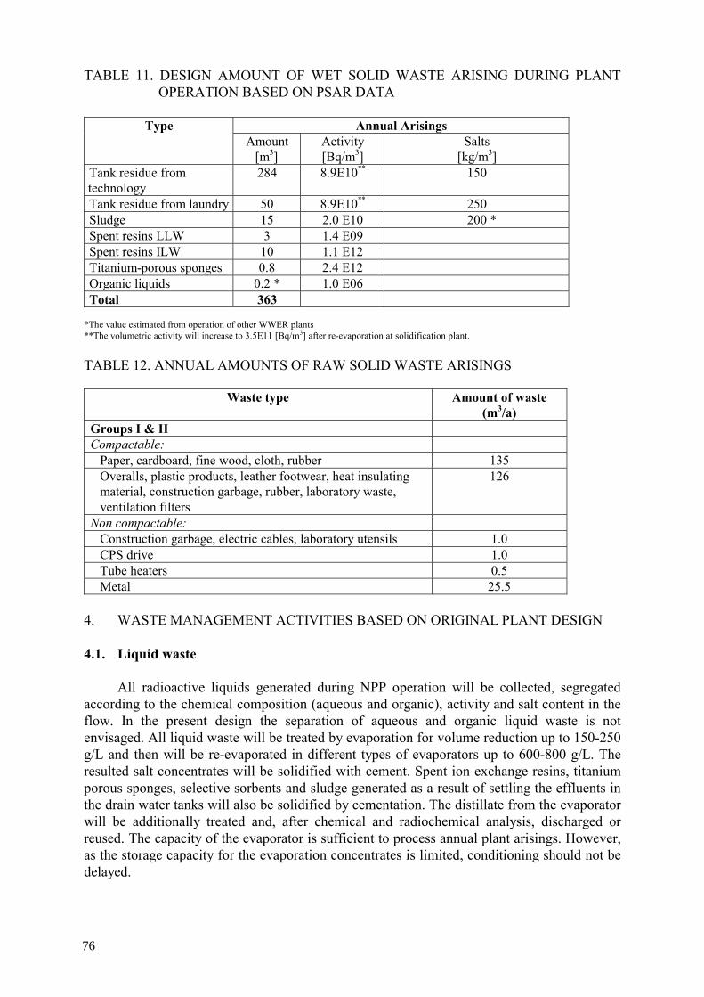
TABLE 11. DESIGN AMOUNT OF WET SOLID WASTE ARISING DURING PLANT OPERATION BASED ON PSAR DATA
Annual Arisings Type
Amount [m3]
Activity [Bq/m3]
Salts [kg/m3]
Tank residue from technology
284 8.9E10** 150
Tank residue from laundry 50 8.9E10** 250 Sludge 15 2.0 E10 200 * Spent resins LLW 3 1.4 E09 Spent resins ILW 10 1.1 E12 Titanium-porous sponges 0.8 2.4 E12 Organic liquids 0.2 * 1.0 E06 Total 363
*The value estimated from operation of other WWER plants **The volumetric activity will increase to 3.5E11 [Bq/m3] after re-evaporation at solidification plant.
TABLE 12. ANNUAL AMOUNTS OF RAW SOLID WASTE ARISINGS
Waste type Amount of waste
(m3/a) Groups I & II Compactable:
Paper, cardboard, fine wood, cloth, rubber 135 Overalls, plastic products, leather footwear, heat insulating material, construction garbage, rubber, laboratory waste, ventilation filters
126
Non compactable: Construction garbage, electric cables, laboratory utensils 1.0 CPS drive 1.0 Tube heaters 0.5 Metal 25.5
4. WASTE MANAGEMENT ACTIVITIES BASED ON ORIGINAL PLANT DESIGN
4.1. Liquid waste
All radioactive liquids generated during NPP operation will be collected, segregated according to the chemical composition (aqueous and organic), activity and salt content in the flow. In the present design the separation of aqueous and organic liquid waste is not envisaged. All liquid waste will be treated by evaporation for volume reduction up to 150-250 g/L and then will be re-evaporated in different types of evaporators up to 600-800 g/L. The resulted salt concentrates will be solidified with cement. Spent ion exchange resins, titanium porous sponges, selective sorbents and sludge generated as a result of settling the effluents in the drain water tanks will also be solidified by cementation. The distillate from the evaporator will be additionally treated and, after chemical and radiochemical analysis, discharged or reused. The capacity of the evaporator is sufficient to process annual plant arisings. However, as the storage capacity for the evaporation concentrates is limited, conditioning should not be delayed.
76

For organic liquids, due to the small amount generated, no provisions for treatment have been made by design. In the case where above treatment methods do not provide satisfactory results, then incineration of such a waste in Esfahan (under construction) will be performed.
4.2. Dry solid waste
The objective of processing of dry solid waste is to reduce its volume and prepare waste packages for storage, transportation and disposal. A dry solid waste management system at the Bushehr NPP consists of:
— Dry solid waste collection, sorting, treatment, and packaging section, and — Temporary storage facility for waste packages inside the building.
4.2.1. Dry solid waste collection, sorting, treatment, and packaging section
Dry solid waste will be collected and sorted out according to the level of its activity,
physical properties and a treatment method at the places of its generation with the use of a radiation monitoring system. The compactable dry solid waste of Group I will be compacted in 200 litre drums by the use of a low force compactor (volume reduction is 3-5). The dry solid waste of Group II will not be treated, just loaded in an appropriate disposable container (polyethylene bags) which will be subsequently loaded into a 200 litre drum or another container with biological shielding. Large-size dry solid waste can be reduced in size (cut, disassembled) at the places of its generation if needed. Waste packages will be produced in compliance with the waste package specifications. Currently, limited information for characterization of the solidified waste is provided in PSAR. A colour distinguished disposable bags, drums or collecting containers will be delivered to unattended rooms during maintenance and repair when waste generation is expected. In periodically attended rooms containers will be installed in specially allocated places.
4.2.2. Temporary storage facility
Based on original design, a storage facility for waste packages is located in the auxiliary
reactor building. The capacity of the facility is 1800 drums that provides for storage of both solid and solidified Group I and II waste within one year. The capacity of the storage facility is insufficient for the amount of the conditioned waste generated during a longer period. Since the national repository will not be ready after one year of reactor operation, an additional interim storage facility with a sufficient capacity up to 10 years is planned, which includes a special place for storage of packaged SRW of group III. The construction of the facility is under negotiation and some review and evaluation of different proposals have been done.
4.3. Gaseous waste
Several systems are introduced by design for treatment of gaseous and airborne wastes before their release to the atmosphere within the discharged limits set by the INRA. They include an exhaust active ventilation system with delay, and iodine and aerosol filters.
77

4. WASTE CONTAINERS AND PACKAGES USED FOR STORAGE AND DISPOSAL
According to PSAR, only one type of final packages (except those used for
transportation and temporary storage) will be used for storage and disposal at BNPP:
— 200 liter steel drums for conditioned waste. Colour distinguished (for Group I, II and III) containers will be provided to facilitate sorting of the conditioned waste.
78
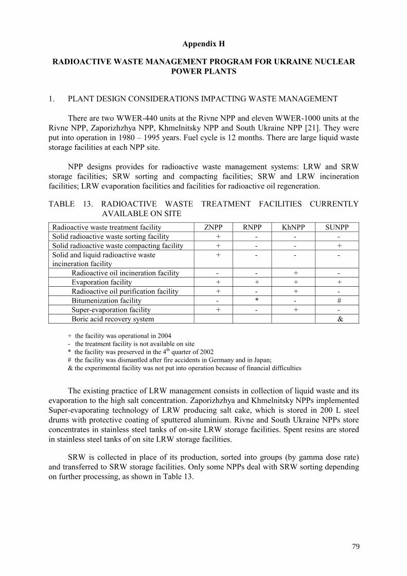
Appendix H
RADIOACTIVE WASTE MANAGEMENT PROGRAM FOR UKRAINE NUCLEAR POWER PLANTS
1. PLANT DESIGN CONSIDERATIONS IMPACTING WASTE MANAGEMENT
There are two WWER-440 units at the Rivne NPP and eleven WWER-1000 units at the
Rivne NPP, Zaporizhzhya NPP, Khmelnitsky NPP and South Ukraine NPP [21]. They were put into operation in 1980 – 1995 years. Fuel cycle is 12 months. There are large liquid waste storage facilities at each NPP site.
NPP designs provides for radioactive waste management systems: LRW and SRW
storage facilities; SRW sorting and compacting facilities; SRW and LRW incineration facilities; LRW evaporation facilities and facilities for radioactive oil regeneration.
TABLE 13. RADIOACTIVE WASTE TREATMENT FACILITIES CURRENTLY AVAILABLE ON SITE
Radioactive waste treatment facility ZNPP RNPP KhNPP SUNPP Solid radioactive waste sorting facility + - - - Solid radioactive waste compacting facility + - - + Solid and liquid radioactive waste incineration facility
+ - - -
Radioactive oil incineration facility - - + - Evaporation facility + + + + Radioactive oil purification facility + - + - Bitumenization facility - * - # Super-evaporation facility + - + - Boric acid recovery system &
+ the facility was operational in 2004 - the treatment facility is not available on site * the facility was preserved in the 4th quarter of 2002 # the facility was dismantled after fire accidents in Germany and in Japan; & the experimental facility was not put into operation because of financial difficulties
The existing practice of LRW management consists in collection of liquid waste and its
evaporation to the high salt concentration. Zaporizhzhya and Khmelnitsky NPPs implemented Super-evaporating technology of LRW producing salt cake, which is stored in 200 L steel drums with protective coating of sputtered aluminium. Rivne and South Ukraine NPPs store concentrates in stainless steel tanks of on-site LRW storage facilities. Spent resins are stored in stainless steel tanks of on site LRW storage facilities.
SRW is collected in place of its production, sorted into groups (by gamma dose rate) and transferred to SRW storage facilities. Only some NPPs deal with SRW sorting depending on further processing, as shown in Table 13.
79
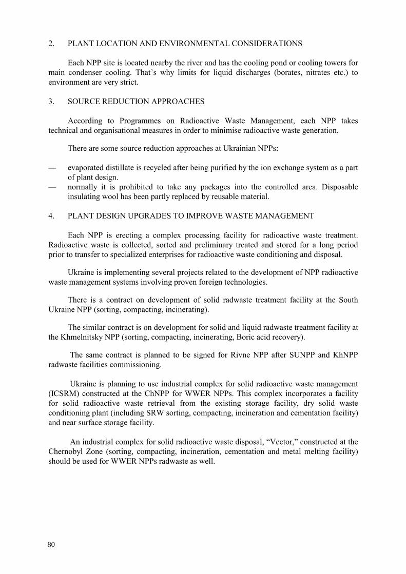
2. PLANT LOCATION AND ENVIRONMENTAL CONSIDERATIONS
Each NPP site is located nearby the river and has the cooling pond or cooling towers for main condenser cooling. That’s why limits for liquid discharges (borates, nitrates etc.) to environment are very strict.
3. SOURCE REDUCTION APPROACHES
According to Programmes on Radioactive Waste Management, each NPP takes technical and organisational measures in order to minimise radioactive waste generation.
There are some source reduction approaches at Ukrainian NPPs:
— evaporated distillate is recycled after being purified by the ion exchange system as a part of plant design.
— normally it is prohibited to take any packages into the controlled area. Disposable insulating wool has been partly replaced by reusable material.
4. PLANT DESIGN UPGRADES TO IMPROVE WASTE MANAGEMENT Each NPP is erecting a complex processing facility for radioactive waste treatment.
Radioactive waste is collected, sorted and preliminary treated and stored for a long period prior to transfer to specialized enterprises for radioactive waste conditioning and disposal.
Ukraine is implementing several projects related to the development of NPP radioactive waste management systems involving proven foreign technologies.
There is a contract on development of solid radwaste treatment facility at the South Ukraine NPP (sorting, compacting, incinerating).
The similar contract is on development for solid and liquid radwaste treatment facility at the Khmelnitsky NPP (sorting, compacting, incinerating, Boric acid recovery).
The same contract is planned to be signed for Rivne NPP after SUNPP and KhNPP radwaste facilities commissioning.
Ukraine is planning to use industrial complex for solid radioactive waste management
(ICSRM) constructed at the ChNPP for WWER NPPs. This complex incorporates a facility for solid radioactive waste retrieval from the existing storage facility, dry solid waste conditioning plant (including SRW sorting, compacting, incineration and cementation facility) and near surface storage facility.
An industrial complex for solid radioactive waste disposal, “Vector,” constructed at the
Chernobyl Zone (sorting, compacting, incineration, cementation and metal melting facility) should be used for WWER NPPs radwaste as well.
80
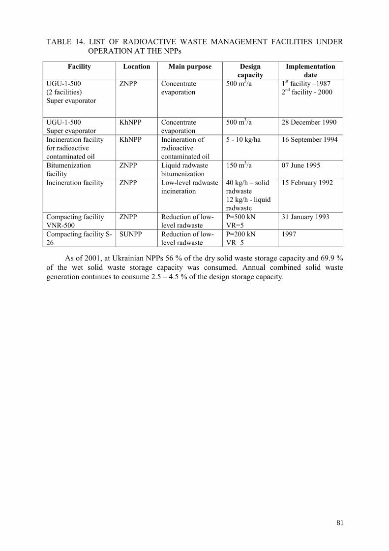
TABLE 14. LIST OF RADIOACTIVE WASTE MANAGEMENT FACILITIES UNDER OPERATION AT THE NPPs
Facility Location Main purpose Design
capacity Implementation
date UGU-1-500 (2 facilities) Super evaporator
ZNPP Concentrate evaporation
500 m3/a 1st facility –1987 2nd facility - 2000
UGU-1-500 Super evaporator
KhNPP Concentrate evaporation
500 m3/a 28 December 1990
Incineration facility for radioactive contaminated oil
KhNPP Incineration of radioactive contaminated oil
5 - 10 kg/ha 16 September 1994
Bitumenization facility
ZNPP Liquid radwaste bitumenization
150 m3/a 07 June 1995
Incineration facility ZNPP Low-level radwaste incineration
40 kg/h – solid radwaste 12 kg/h - liquid radwaste
15 February 1992
Compacting facility VNR-500
ZNPP Reduction of low-level radwaste
Р=500 kN VR=5
31 January 1993
Compacting facility S-26
SUNPP Reduction of low-level radwaste
P=200 kN VR=5
1997
As of 2001, at Ukrainian NPPs 56 % of the dry solid waste storage capacity and 69.9 % of the wet solid waste storage capacity was consumed. Annual combined solid waste generation continues to consume 2.5 – 4.5 % of the design storage capacity.
81

TABLE 15. SOLID RADIOACTIVE WASTE MANAGEMENT COMPLEX AT CHNPP AND IN CHERNOBYL ZONE
Facility Location Main purpose Implementation
date
Industrial complex for dry solid radioactive waste management: 1. Dry solid radioactive waste treatment plant including:
− solid waste buffer storage facility; − solid waste sorting and
fragmentation facility; − incineration facility; − compacting facility; − grouting facility; − system for management of high-level
dry solid waste and low-, intermediate-level long-lived dry solid waste;
− on-site transportation system; − off-site transportation system;
2. Solid radioactive waste retrieval facility 3. Engineered near-surface disposal facility for low- and intermediate-level short-lived solid radioactive waste
ChNPP site “Vector” site
Management of radioactive waste accumulated in ChNPP operation; radioactive waste that will be generated in ChNPP decommissioning and related activities. It is planned for WWER radwaste management too.
Under design
82

TABLE 16. NPP RADIOACTIVE WASTE INVENTORY OF NNEGC ENERGOATOM
Material Location Volume, m3 Activity, Bq Filter materials* KhNPP 135,2 5,06E+11 Concentrate* KhNPP 395,1 9,58E+12 SALT cake KhNPP 551,2 4,5E+13 Solid radwaste of I group ** KhNPP 2489,4 Solid radwaste of II group ** KhNPP 95,3 Solid radwaste of III group ** KhNPP 6,5 Filter materials* KhNPP 340,0 4,07E+10 Concentrate * ZNPP 2662,0 9,94E+12 SALT cake ZNPP 2113,0 5,47E+13 Solid radwaste of I group *** ZNPP 4373,0 8,58E+09 Solid radwaste of II group *** ZNPP 3259,0 5,44E+12 Solid radwaste of III group *** ZNPP 43,4 7,80E+12 Filter materials SUNPP 177,4 Concentrate * SUNPP 2756,0 1,20E+14 Solid radwaste of I group ** SUNPP 13910,0 Solid radwaste of II group ** SUNPP 344,0 Solid radwaste of III group ** SUNPP 10,8 Filter materials RNPP 730,0 8,72E+12 Concentrate * RNPP 5303,0 1,66E+14 Solid radwaste of I group ** RNPP 2501,9 Solid radwaste of II group ** RNPP 21,1 Solid radwaste of III group ** RNPP 31,5
* - There is no methodology for determining mass of filter materials and bottoms at SE NPP ** - Solid radwaste activity and mass are not determined due to the absence of methodologies and equipment *** - Approximate data obtained by calculation
Radionuclide content of solid radwaste is not determined due to the absence of
methodologies and equipment.
83


Appendix I
RADIOACTIVE WASTE MANAGEMENT AT BALAKOVO, KALININ, KOLA, NOVOVORONESH AND ROSTOV NUCLEAR POWER PLANTS
1. PLANT DESIGN CONSIDERATIONS IMPACTING WASTE MANAGEMENT
There are 14 WWER reactor units in operation in Russia, two reactor units are waiting for decommissioning [22]. All NPPs are incorporated in ROSENERGOATOM Corporation. The activities in the area of radioactive waste management is based on “Working Program on Radioactive Waste Management at NPPs of the ROSENERGOATOM Corporation in the period from 2003 to 2008.” Working Program is upgrading every year. The Program is supervised by ROSENERGOATOM Corporation .
2. PLANT LOCATION AND ENVIRONMENTAL CONSIDERATIONS
All NPPs are located in Europe part of Russia. It should be noted that despite of implementation of Working Program there are the
following main drawbacks in the area of radioactive waste management at Russian NPPs:
— The volume of LLW generated at Russian NPPs is greater than that of LLW of Western NPPs.
— At the majority of Russian NPPs the full set of facilities for the conditioning of liquid and solid LLW are not available. In particular the solidification facility (bituminization) is in operation at Kalinin NPP only.
— At Russian NPPs a considerable part of RW is stored in a form that cannot be considered as a conditioned form. In particular the end product of deep evaporation facilities type UGU-500 at Balakovo NPP and at Novovoronesh NPP is salt cake in steel packages.
— Disposal facilities are not available. The goal of the Working Program is to solve these problems. The status with filling of storage facilities of NPPs at the end of 2002:
— The total amounts of stored liquid waste is about 19000 m3 — The total amounts of as-generated dry solid waste is about 50,000 m3
The capacity of storage facilities for evaporator concentrates and spent resins is
consumed from 42% (Kola NPP) to 83% (Novovoronesh NPP). The capacity of storage facilities for dry solid radioactive waste is consumed from 45%
(Kola NPP) to 70% (Novovoronesh NPP).
3. SOURCE REDUCTION APPROACHES Conception of improvement of radioactive waste management at Russian NPPs according
to Working Program mentioned above is based on the following:
85

Minimization of primary LLW that includes:
— Compliance with annual authorized limits for generated LLW amounts (Table 17)
TABLE 17. AUTHORIZED ANNUAL LIMITS FOR LLW GENERATION AT WWER NPPS PER REACTOR UNIT)
Primary
LRW as-generated
m3/a
Conditionedevaporator
concentratesm3/a
Salt content of
conditioned LRW t/a
Spent filtering
materials m3/a
SRW m3/a
WWER-440 Design V-179
25000 140 70 10 120
WWER-440 Design V-213
15000 140 55 7 120
WWER-440 Design V-230
15000 140 50 15 250
WWER-440 Design V-320 and V338
11000 120 35 15 250
WWER-440 Design V-187
14500 100 45 15 250
Where: LRW = liquid radioactive waste and SRW = solid radioactive waste according to Russian LLW classification.
— Commissioning of more effective technologies producing small quantities of LLW (decontamination, washing, etc.)
— Financial motivation of personnel in terms of LLW production minimization
LLW processing to produce non-radioactive waste and sending it to industrial landfill or reuse, that includes: — Implementation of ion-selective sorption processes for purifying evaporation concentrate.
— Development of spent resin deep decontamination process
— Decontamination and melting of contaminated metal for reuse In the LLW production, a decreasing trend at Russian WWER NPPs is demonstrated by
the Table 18.
86
TABLE 18. LLW GENERATION REDUCTION TREND AT WWER NPPS (TOTAL QUANTITIES FROM ALL RUSSIAN NPPS)
4002002
64411362001
153210582000
145712851999
220613951998
216917721997
Solid radioactive waste, m3/year
Salt quantitiesin liquid radioactive waste, t/year
Years
4002002
64411362001
153210582000
145712851999
220613951998
216917721997
Solid radioactive waste, m3/year
Salt quantitiesin liquid radioactive waste, t/year
Years
4. PLANT DESIGN UPGRADES TO IMPROVE WASTE MANAGEMENT The following new technologies are currently used at NPPs:
— Contaminated cloth washing process that generates small quantities of liquid waste — Licensed NSK-150-1.5P 1.5 m3 type containers of reinforced concrete for LLW long
term storage (at Novovoronesh NPP)
Following measures to improve waste management are planned according to the Working Program mentioned above:
— Commissioning of cementation technologies at NPPs with loading the end-product into
containers for long term storage and disposal — Commissioning of processing facilities for dry solid waste treatment complexes
including sorting, compacting and incineration facilities at all NPPs — Preferential use of NSK-150-1.5P-type 1.5 m3 containers of reinforced concrete for
storage and disposal of conditioned LLW
87

TABLE 19. PROJECTED EXPANSION OF NEW LLW MANAGEMENT FACILITIES PURSUANT TO THE WORKING PROGRAM
Facilities
Balakovo NPP
Kalinin NPP
Kola NPP
Novovoronesh NPP
Rostov NPP
Bitumenization (modernization/backfit)
2004 2004
Cementation 2005 2004 Ion-selective sorption (for evaporator concentrate cleaning)
2004 2005
Melting of metal and thermal coating
2004 2005 2006 2005 2005
Compaction 2004 2005 Incineration 2004 2005 2004 Sorting and fragmentation of dry solid waste
2004 2004 2004
The following new technologies are under development and testing:
— Melting of metal and thermal coatings based on cold crucible. — Ion-selective sorption for purifying evaporation concentrate to reach non-radioactive
condition. — NSK-150-1.5P containers for salt cake storage.
5. WASTE CONTAINERS AND PACKAGES USED FOR STORAGE AND DISPOSAL
Basic ideas in this area are the following:
— Conditioned waste is stored on site NPP until commissioning of disposal facilities. — Conditioned waste is mainly stored in NSK-150-1.5P-type 1.5 m3 containers of
reinforced concrete. Containers are not intended for repackaging. — Construction of container-type storage facilities on site NPPs.
88

REFERENCES
[1] INTERNATIONAL ATOMIC ENERGY AGENCY, Radioactive Waste Management
Glossary, 2003 Edition, IAEA, Vienna (2003). [2] INTERNATIONAL ATOMIC ENERGY AGENCY, Application of Ion Exchange
Processes for the Treatment of Radioactive Waste and Management of Spent Ion Exchangers, Technical Report Series No. 408, IAEA, Vienna (2002).
[3] INTERNATIONAL ATOMIC ENERGY AGENCY, Application of the Concepts of Exclusion, Exemption and Clearance, IAEA Safety Guide RS-G-1.7, IAEA, Vienna (2004).
[4] INTERNATIONAL ATOMIC ENERGY AGENCY. International Basic Safety Standards for Protection against Ionizing Radiation and for the Safety of Radiation Sources, Safety Series No. 115, IAEA, Vienna (1996).
[5] EUROPEAN COMMISSION, Principles and Methods for Establishing Concentrations and Quantities (Exemption Values) Below Which Reporting is not Required in the European Directive, EC Radiation Protection Report No. 65, 1993
[6] INTERNATIONAL ATOMIC ENERGY AGENCY, Clearance Levels for Radionuclides in Solid Materials; Application for Exemption Principles, IAEA-TECDOC-855, IAEA, Vienna (1996).
[7] INTERNATIONAL ATOMIC ENERGY AGENCY, Regulatory Control of Radioactive Discharges to the Environment, IAEA Safety Standards Series No. WS-G-2.3, IAEA, Vienna (2003).
[8] KALLONEN, I., Management of Radioactive Wastes at the Loviisa NPP in Finland, EPRI International LLW Conference, July 19-21, 2002, Colorado Springs, Colorado, US.
[9] INTERNATIONAL ATOMIC ENERGY AGENCY, Processing of Nuclear Power Plant Waste Streams Containing Boric Acid, IAEA-TECDOC–911, IAEA, Vienna (1996).
[10] SMIESKO, I., PECHA, M., Regeneration of Boric Acid from NPP Bohunice Waste Streams, Final Report, IAEA TC Project SLR/4/006, 1999.
[11] BERTHOLDT, H., WILLE, H., Full System Decontamination, The Loviisa 2 experience, Nuclear Engineering International, March 1995.
[12] WAHLSTRÖM, B., Full-System Decontamination of Loviisa-2, Nuclear Europe Worldscan, No. 11-12, 1994.
[13] INTERNATIONAL ATOMIC ENERGY AGENCY, Recycle and Reuse of Materials and Components from Waste Streams of Nuclear Fuel Cycle Facilities, IAEA-TECDOC-1130, IAEA, Vienna (2000).
[14] ORMAI, P., SCHUNK, J., New Challenges in the Radioactive Waste Management at the Hungarian NPP, EPRI LLW 2003 Conference, New Orleans, Louisiana, US.
[15] SMIESKO, I., Radioactive Waste Management Experience at WWER Type Nuclear Power Plant Jaslovske Bohunice, EPRI International LLW Conference, July 19-21, 2002, Colorado Springs, Colorado, US.
[16] BURCL, R., Radioactive Waste Management at WWER/Type Reactors, Management of Radioactive Waste from Nuclear Power Plants, IAEA and INSTN, September 9- October 4 1996, Paris-Saclay, France.
[17] KALLONEN, I., Radioactive Waste Management at Loviisa NPP in Finland, IAEA’s Technical Co-operation Meeting in “Ukrainian NPPs Radioactive Waste Management-Radioactive Waste Minimization issues” , Kiev, Ukraine, November 13-17, 1995.
[18] TUSA, E., IVO’s Nuclide Removal System Takes to the Road, Waste Management, July 1995.
89
[19] VISZLAY, J., Methods for Boron Removal from Nuclear Power Plant Waste Streams and its subsequent Recovery, IAEA Advisory Group Meeting, IAEA, Vienna, October, 1995.
[20] KALLONEN, I., NURES experiences in Finland, Estonia and Russia; VIIIth International Conference of Water Chemistry of Nuclear Reactor Systems, Bournemouth, UK, 22-26 October 2000.
[21] BYKOV, V. Management of Radioactive Wastes at NPPs in Ukraine, IAEA TM, June 14-18, Vienna, Austria, 2004.
[22] SUKHANOV, L., A.A. Bochvar Research and Scientific Institute of inorganic materials, Moscow, From “Working Program on Radioactive Management at NPPs of the ROSENERGOATOM Corporation in the Period from 2003 to 2008,” IAEA TM, June 14-18, Vienna, Austria, 2004.
[23] ELECTRIC POWER RESEARCH INSTITUTE, Advanced Volume Reduction and Waste Segregation Strategies for Low Level Waste Disposal, EPRI TR-1003436, Palo Alto, California, US, September 2003.
[24] WASTE MANAGEMENT DEPTARTMENT OF AEOI, National Radioactive Waste Management Strategy in I.R. of IRAN, Rev. 1, December 2003.
[25] OJOVAN, M., BURCL, R., Vitrification of LILW: Technology and Product Performance, 2003 EPRI Int. Conference, (Proc. Int. Conference, Colorado Springs, US, July 2003), EPRI, 2003.
[26] PARK, J.K., SONG, M.J., Feasibility Study on Vitrification of Low and Intermediate Level Radioactive Waste from Pressurized Water Reactors, Waste Management, 18, pp. 157-167, 1998.
[27] KALLONEN, I., Purification of Radioactive Liquid Wastes at Paldiski in Estonia and at Murmansk in Russia, (Proceedings International Conference on “Radioecological Safety in the Russian and European North”, Severodvinsk, Russia), 18-23 November 1996.
[28] KALLONEN, I., NURES Experiences in Finland, Estonia, and Russia; Federal Nuclear and Radiation Safety Authority of Russia (Meeting on Waste Management); 21-24 September 1999, Cheljabinsk, Russia, 1999.
[29] INTERNATIONAL ATOMIC ENERGY AGENCY, Characterization of Radioactive Waste Forms and Packages, Technical Reports Series No. 383, IAEA, Vienna (1997).
[30] INTERNATIONAL ATOMIC ENERGY AGENCY, Radioactive Waste Arising in Various Nuclear Fuel Cycles, IAEA-TECDOC (in preparation).
[31] INTERNATIONAL ATOMIC ENERGY AGENCY, Radioactive Waste Management Status and Trends, No. 2, (CD-ROM), IAEA, Vienna (2002).
[32] INTERNATIONAL ATOMIC ENERGY AGENCY, Advances in Technologies for the Treatment of Low and Intermediate Level Radioactive Liquid Wastes, Technical Reports Series No. 377, IAEA, Vienna (1995).
[33] ELECTRIC POWER RESEARCH INSTITUTE. TR-109655, Non-Metal Filter Study, Palo Alto, CA, US, November 2004.
[34] INTERNATIONAL ATOMIC ENERGY AGENCY, Status of Technology for Volume Reduction and Treatment of Low and Intermediate Level Solid Radioactive Waste, Technical Reports Series No. 360, IAEA, Vienna (1994).
[35] INTERNATIONAL ATOMIC ENERGY AGENCY, Containers for Packaging of Solid Low and Intermediate Level Radioactive Wastes, Technical Reports Series No. 355, IAEA,Vienna (1993).
[36] ELECTRIC POWER RESEARCH INSTITUTE, DAW and Mixed LLW Volume Reduction Technologies, Report EPRI TR-107331, December 1999.
[37] TESHIMA, T., KARITA, K., OKAMOTO, O., OHNO, H. Radionuclides Behaviour in Induction Heat Melting and Its Products for Non-Combustible Solid Waste, 1993
90
International Conference on Nuclear Waste Management and Environmental Remediation, Vol.3, pp705-710, 1993.
[38] KULOVANY, J., Radioactive Waste Treatment Technology at Dukovany NPP, Inter-regional WANO Workshop on Radioactive Waste and Spent Fuel Management, Trebic, Czech Republic, 27-29 January 2000.
[39] KULOVANY, J., Minimization of Radwaste Production in NPP Dukovany, Annual Conference of Bulgarian Nuclear Society 2001, 16-21 June 2001.
91


ABBREVIATIONS
ALARA As low as reasonably achievable BNPP Bushehr Nuclear Power Plant CA Contaminated area ChNPP Chernobyl Nuclear Power Plant COD Chemical oxygen demand EW Exempted waste, consistent with the concept of “clearance” in Reference 7 FRC Fiber reinforced concrete HWGCR Heavy water gas cooled reactor ICRP International commission on radiological protection ICSRM Industrial complex for solid radioactive waste management INRA Iran Nuclear Power Authority KhNPP Khmelnitski Nuclear Power Plant KNPP Kozloduy Nuclear Power Plant LILW Low and intermediate level waste LLW Low level radioactive waste LRW Liquid radioactive waste NPP Nuclear power plant PSAR Preliminary safety analysis report PVA Polyvinyl alcohol PWR Pressurized water reactor RAW Radioactive waste RNPP Rovno Nuclear Power Plant RCA Radiological control area SRW Solid radioactive waste
93

SUNPP South Ukraine Nuclear Power Plant TRU Transuranic element VR Volume reduction coefficient WAC Waste acceptance criteria WWER Water moderated, water cooled energy reactor ZNPP Zaporozhe Nuclear Power Plant
94

CONTRIBUTORS TO DRAFTING AND REVIEW
Alexiev, A. Kozloduy NPP, Bulgaria
Burcl, R. International Atomic Energy Agency
Bykov, V. State Nuclear Regulatory Committee of Ukraine, Ukraine
Chubetsov, S.B. Research Institute for Nuclear Power Plant Operation, Russian Federation
Fellingham, L.R. RWE NUKEM Ltd, United Kingdom
González Gómez, J.L. International Atomic Energy Agency
Hanus, V. Jaderna Elektrarna Temelin, Czech Republic
Jindrich, K. State Office for Nuclear Safety, Czech Republic
Kallonen, I. Fortum Nuclear Services, Ltd, Finland
Kelly, J.J. ERS International, Inc., United States of America
Kopecky, P. NPP Dukovany, Czech Republic
Kourilo, D.A. NPP Zaporozhye, Ukraine
Luppov. V. VNIIAES, Russian Federation
Momenzadeh, S. Atomic Energy Organization of Iran, Iran
Ormai, P. Public Agency for Radioactive Waste Management, Hungary
Sukhanov, L. A.A. Bochvar All-Rusian Scientific Research Institute for Inorganic Materials, Russian Federation
Schunk, J. Paks Nuclear Power Plant, Ltd, Hungary
Smiesko, I. Slovak Electric j.s.c., NPP Bohunice, Slovakia
Consultants Meetings, 1st Report Initiative Vienna, Austria 26–30 May 1997, 9–12 November 1999, 3–7 April 2000
Consultants Meetings, 2nd Report Initiative
Vienna, Austria: 22–26 September 2003, 5–9 September 2005
Technical Meeting, 2nd Report Initiative Vienna, Austria: 14–18 June 2004
95