Embed Size (px)
Citation preview

Topical Reportsubmitted to
The Department of Energy (DoE)National Energy Technology Laboratory (NETL)
under
Contract # DE-FC26-04NT42264
for
PHASE I TOPICAL REPORT
Reporting Period:10-01-2004 to 12-31-2005
compiled as part of the project titled
Explorer-II:
Wireless Self-powered Visual and NDE Robotic Inspection System for Live Gas Distribution Mains
Document Number: REP-GOV-DOE-051231
Date of Submission:January 31st, 2006
submitted by
Carnegie Mellon UniversityThe Robotics Institute - REC
#10 on 40th StreetPittsburgh, PA 15201
(412) 268-2000
Administrative Contact:Susan Burkett
Technical Contact:Hagen Schempf, Ph.D.

Explorer-II:Wireless Self-powered Visual and NDE Robotic Inspection System for Live Gas Distribution Mains
Topical Report - Design Phase i
DISCLAIMER
This report was prepared as an account of work co-sponsored by an agency of the United States Government. Neither the United States Government nor any agency thereof, nor any of their employees, makes any warranty, express or implied, or assumes any legal liability or responsibility for the accuracy, completeness, or usefulness of the information, apparatus, product, or process disclosed, or represents that its use would not infringe privately owned rights. Reference herein to any specific commercial product, process, or service by trade name, trademark, manufacturer, or otherwise does not necessarily constitute or imply its endorsement, recommendation, or favoring by the United States Government or any agency thereof. The views and opinions of authors expressed herein do not necessarily state or reflect those of the United States Government or any agency thereof.
This report was also prepared by Automatika, Inc. (AI) as an account of work co-sponsored by the Northeast Gas Association (NGA). Neither NGA, members of NGA nor AI, nor any other party acting on behalf of any of them:
(a) makes any warranty or representation, express or implied, with respect to the accuracy, completeness, or usefulness of the information contained in this report, or that the use of any information, apparatus, method, or process disclosed in this report may not infringe privately owned rights; or
(b) assumes any liability with respect to the use of, or for damages resulting from the use of, any information, apparatus, method, or process disclosed in this report.

Explorer-II:Wireless Self-powered Visual and NDE Robotic Inspection System for Live Gas Distribution Mains
Topical Report - Design Phase ii
I. EXECUTIVE SUMMARY
Carnegie Mellon University (CMU) under contract from Department of Energy/National Energy Technology Laboratory (DoE/NETL) and co-funding from the Northeast Gas Association (NGA), has completed the overall system design of the next-generation Explorer-II (X-II) live gas main NDE and visual inspection robot platform. The design is based on the Explorer-I prototype which was built and field-tested under a prior (also DoE- and NGA co-funded) program, and served as the validation that self-powered robots under wireless control could access and navigate live natural gas distribution mains (see Figure I):
Figure I : Prototype of Explorer-I and field-trial settings, to serve as basis for the current X-II program
The X-II system design (~8 ft. and 66 lbs.) was heavily based on the X-I design, yet was substantially expanded to allow the addition of NDE sensor systems (while retaining its visual inspection capability), making it a modular system, and expanding its ability to operate at pressures up to 750 psig (high-pressure and unpiggable steel-pipe distribution mains). A new electronics architecture and on-board software kernel were added to again improve system performance. A locating sonde system was integrated to allow for absolute position-referencing during inspection (coupled with external differential GPS) and emergency-locating. The power system was upgraded to utilize lithium-based battery-cells for an increase in mission-time. The resulting robot-train system with CAD renderings of the individual modules, is depicted in Figure II:
Figure II : Overall image of the Explorer-II robot and its main modules.
1 of 10

Explorer-II:Wireless Self-powered Visual and NDE Robotic Inspection System for Live Gas Distribution Mains
Topical Report - Design Phase iii
The system architecture now relies on a dual set of end camera-modules to house the 32-bit processors (Single-Board Computer or SBC) as well as the imaging and wireless (off-board) and CAN-based (on-board) communication hardware and software systems (as well as the sonde-coil and -electronics). The drive-module (2 ea.) are still responsible for bracing (and centering) to drive in push/pull fashion the robot train into and through the pipes and obstacles. The steering modules and their arrangement, still allow the robot to configure itself to perform any-angle (up to 90 deg) turns in any orientation (incl. vertical), and enable the live launching and recovery of the system using custom fittings and a (to be developed) launch-chamber/-tube. The battery modules are used to power the system, by providing power to the robot’s bus. The support modules perform the functions of centration for the rest of the train as well as odometry pickups using incremental encoding schemes. The electronics architecture is baed on a distributed (8-bit) microprocessor architecture (at least 1 in ea. module) communicating to a (one of two) 32-bit SBC, which manages all video-processing, posture and motion control as well as CAN and wireless communications. The operator controls the entire system from an off-board (laptop) controller, which is in constant wireless communication with the robot train in the pipe. The sensor modules collect data and forward it to the robot operator computer (via the CAN-wireless communications chain), who then transfers it to a dedicated NDE data-storage and post-processing computer for further (real-time or off-line) analysis.CMU has fully designed every module in terms of the mechanical, electrical and software elements (architecture only). Substantial effort has gone into pre-prototyping to uncover mechanical, electrical and software issues for critical elements of the design. Design requirements for sensor-providers were also detailed and finalized and provided to them for inclusion in their designs. CMU is expecting to start 2006 with a detailed design effort for both mechanical and electrical components, followed by procurement and fabrication efforts in late winter/spring 2006. The assembly and integration efforts will occupy all of the spring and summer of 2006. Software development will also be a major effort in 2006, and will result in porting and debugging of code on the module- and train-levels in late summer and Fall of 2006. Final pipe mock-up testing is expected in late fall and early winter 2006 with an acceptance demonstration of the robot train (with a sensor-module mock-up) planned to DoE/NGA towards the end of 2006.

Explorer-II:Wireless Self-powered Visual and NDE Robotic Inspection System for Live Gas Distribution Mains
Topical Report - Design Phase iv
Table of Contents
I. EXECUTIVE SUMMARY
I. INTRODUCTION
II. BACKGROUND1.0 Prior Art .............................................................................................................................22.0 Explorer-I System Background........................................................................................43.0 Field-trial Results to Date .................................................................................................6
III. SYSTEM DESIGN1.0 Requirements and Specifications .....................................................................................9
1.1 Performance Requirements...............................................................................................91.2 Robot Train Specifications ...............................................................................................9
2.0 Prototype Design ..............................................................................................................102.1 Camera-Module Design ..................................................................................................11
2.1.1 Overall Assembly .........................................................................................................112.1.2 Locating Sonde ............................................................................................................12
2.2 Steering-Module Design .................................................................................................132.3 Drive-Module Design .....................................................................................................142.4 Support-Module Design..................................................................................................152.5 Battery-Module Design...................................................................................................152.6 Launcher Design .............................................................................................................162.7 Electronics Architecture Design .....................................................................................172.8 Software Architecture Design.........................................................................................17
3.0 Sensor-Module Specifications .........................................................................................193.1 Overall Requirements .....................................................................................................193.2 Mechanical Interface.......................................................................................................203.3 Sensor Wiring Schematic................................................................................................203.4 CAN Bus Isolation Schematic ........................................................................................21
IV. PRE-PROTOTYPING & EXPERIMENTATION1.0 Pressure Testing...............................................................................................................222.0 Computing-System testing ..............................................................................................223.0 Illumination System Testing ...........................................................................................224.0 Arm Jig .............................................................................................................................235.0 Prototype Electronics for testing ....................................................................................236.0 Pre-prototype partial robot train ...................................................................................23
V. ACKNOWLEDGEMENTS
VI. REFERENCES
IX. APPENDICES1.0 Gas Pipeline Robot State-of-the-Art Review.................................................................26
1.1 Introduction - Pipe Robots ..............................................................................................261.2 Background.....................................................................................................................26

Explorer-II:Wireless Self-powered Visual and NDE Robotic Inspection System for Live Gas Distribution Mains
Topical Report - Design Phase v
1.2.1 Water and Sewer Mains ...............................................................................................261.2.2 Oil- and Gas Pipelines.................................................................................................27
1.2.2.1 Transmission Mains - Pipe Pigs ........................................................................................... 271.2.2.2 Oil- and Gas-Wells - Tethered & Autonomous Robots ....................................................... 281.2.2.3 Distribution Mains - Stick-Cameras .................................................................................... 281.2.2.4 Distribution Mains - Pipe Crawlers .................................................................................... 281.2.2.5 Other applications ............................................................................................................... 29
1.3 Platform Comparison......................................................................................................301.4 References.......................................................................................................................32

Explorer-II:Wireless Self-powered Visual and NDE Robotic Inspection System for Live Gas Distribution Mains
Topical Report - Design Phase vi
List of Figures
Figure I : Prototype of Explorer-I and field-trial settings, to serve as basis for the current X-II pro-gram ........................................................................................................................ ii
Figure II : Overall image of the Explorer-II robot and its main modules....................................... iiFigure I : Prior art in-pipe inspection systems.................................................................................2Figure II : Tethered gasmain (CISBOT - right; GRISLEE - bottom) and untethered autonomous
(Kurt I) robots developed to date by industry and researchers ................................3Figure III : Explorer - Pipe Inspection System ................................................................................4Figure IV : Overall layout of Explorer ............................................................................................4Figure V : Live-access launching hardware systems.......................................................................6Figure VI : Live CI New York Field-Trial setting...........................................................................6Figure VII : Operator Interface & visible features (tap, bottle-caps, wheel-tracks) ........................7Figure VIII : Explorer live deployment in a high-pressure steel main ............................................7Figure IX : Overall X-II robot train layout with module identification.........................................10Figure X : Overall drive-module CAD image ...............................................................................11Figure XI : Overall multi-angle view of the forward/rearward nose- or camera-module .............11Figure XII : Locating sonde coil and PCB design, as well as COTS locating equipment ............12Figure XIII : Multiple end-views of the roll- and pitch steering module ......................................13Figure XIV : Drive-module design overview ................................................................................14Figure XV : Multi-view CAD rendering of drive-module design .................................................14Figure XVI : Support Module Overview Design...........................................................................15Figure XVII : Multi-view CAD rendering of the support-module ................................................15Figure XVIII : Overall design of the battery module ....................................................................15Figure XIX : Exploded and rendered views of the battery module design....................................16Figure XX : Preliminary angled launcher design for Explorer-II..................................................16Figure XXI : Overall Explorer-II (X-II) electronics architecture ..................................................17Figure XXII : X-II robot platform software architecture...............................................................18Figure XXIII : Mechanical size and shape specifications for the sensor module..........................20Figure XXIV : Sensor module wiring interface diagram requirements.........................................20Figure XXV : CAN bus sensor module isolation requirement schematic .....................................21Figure XXVI : Pressure test-chamber system................................................................................22Figure XXVII : 32-bit SBC OEM components used in testing .....................................................22Figure XXVIII : Higher efficiency white LED illuminator test setup...........................................22Figure XXIX : Prototype LED illuminator ring and test-camera setup.........................................23Figure XXX : Drive-arm strain-gauge and leg-expand/-collapse test-jig......................................23Figure XXXI : Prototype module control PCBs............................................................................23Figure XXXII : Pre-prototype robot-train section(s) assembly .....................................................23

Explorer-II:Wireless Self-powered Visual and NDE Robotic Inspection System for Live Gas Distribution Mains
Topical Report - Design Phase vii
List of Tables
Table 1-1 : High-level performance requirements listing................................................................9Table 1-2 : Robot-train system specifications listing ....................................................................10Table 1-3 : X-II weight breakdown (design-estimate)...................................................................11Table 1-4 : Sensor Module Interface Specifications......................................................................19

Explorer-II:Wireless Self-powered Visual and NDE Robotic Inspection System for Live Gas Distribution Mains
Topical Report - Design Phase 1
I. INTRODUCTION
CMU is continuing its in-pipe robotic system development through the development of Explorer-II (X-II), which is based on the previous Explorer design. X-II represents a leap in the capabilities of Explorer-I (see inset image for Explorer-I prototype). The intent is to develop a generic platform capable of carrying a variety of interchangeable sensor modules, to perform self-powered wireless-controlled inspections of gas mains at up to transmission-line pressures (< 750 psig). The principle of operation is similar to that of Explorer-I: launch the system in a no-blow condition into a live gas main using OEM fittings with a custom launcher (see image below for pre-prototype fitting-access hardware with staged locomotor), traverse a set distance of pipe while performing NDE and visual cataloging measurements - all of it under self-powered and remote teleoperated wireless control from the surface utilizing (an) in-pipe antenna(e).
The technical implementation being implemented, as detailed by the CAD renderings provided in this topical report, relies on the powered wheel-arms, capable of deploying into varied-diameter pipe sizes, with turning and climbing capabilities (primarily for launch and recovery). In order to accommodate visual as well as visual-plus-NDE inspection modalities, the modules was designed for in-the-field modular exchange (mechanical and electrical interconnections), with additional modules to provide power
(battery-module) and self-centering ability (support-module). Note that due to the nature of launching and inspection in varied pipe-diameters, the sensor-module will require articulation for the sensor-head(s), indicating an involved sensor-module design and increased controller and data-acquisition complexity.

Explorer-II:Wireless Self-powered Visual and NDE Robotic Inspection System for Live Gas Distribution Mains
Topical Report - Design Phase 2
II. BACKGROUND
US gas companies spend over $300 million annually detecting and repairing gas leaks in urban and suburban settings. The current approach is one of above ground leak detection and pinpointing, followed by excavation, repair and restoration. The major cost incurred is typically that of digging and restoring the excavation site. If a tool was available that could provide real-time and long-term inspection capabilities in order to allow for rapid and pre-planned inspections and repairs wherever needed, national utilities would be able to better manage and allocate their operating and repair budgets, potentially reducing costly emergency repairs.
1.0 Prior ArtIn the area of in-pipe inspection systems, there are many examples of prior-art robotic systems for use in underground piping (transmission-pipeline pigs excluded). Most of them however are focussed on water- and sewer-lines, and meant for inspection, repair and rehabilitation (Pearpoint, Beaver, KA-TE, etc.). As such, they are mostly tethered, utilizing cameras and specialized tooling, etc. (see Figure I).
Figure I : Prior art in-pipe inspection systems
Three of the more notable exceptions are the autonomous Kurt I system from GMD (Germany) used for sewer monitoring (not commercial nor hardened), the (albeit tethered) cast-iron pipe joint-sealing robot (CISBOT; ConEd), which is deployed through a bolt-on fitting and injects anaerobic
KA-TE
PearpointBaker-Hughes
Advantica
Advantica
BeaverBlackHawk

Explorer-II:Wireless Self-powered Visual and NDE Robotic Inspection System for Live Gas Distribution Mains
Topical Report - Design Phase 3
sealant into the leaking jute-stuffed joint, and GRISLEE (GTI, CMU & MTI), a coiled-tubing tether deployed inspection, marking and in-situ spot-repair system. These systems are shown in Figure II:
Figure II : Tethered gasmain (CISBOT - right; GRISLEE - bottom) and untethered autonomous (Kurt I) robots developed to date by industry and researchers
A more in-detail treatise on the prior ar tin this and related fields, can be found in Section IX. APPENDICES on page 26.

Explorer-II:Wireless Self-powered Visual and NDE Robotic Inspection System for Live Gas Distribution Mains
Topical Report - Design Phase 4
2.0 Explorer-I System BackgroundThe Northeast Gas Association (NGA) and its NYSEARCH research-arm, DoE (current) and NASA (past), funded a program at Carnegie Mellon University’s (CMU) Robotics Institute (RI) to develop an advanced remote and robotic inspection system, capable of multi-mile long-duration travel inside live gas mains for in-situ assessment and pipe-network cataloging.Under this program, CMU has developed Explorer, a real-time remotely controllable, modular visual inspection robot system for the in-situ inspection and imaging of live 6- and 8-inch diameter distribution gas-mains (see Figure III for an image of the prototype in a test network setting). Explorer is capable of locomoting through straight pipe segments and sharp bends, elbows, Ys and Ts, using a combination of its on-board driving-arms and steering-joints. The system is sealed and purged (and thus can safely operate in natural gas environments) and capable of negotiating wet and partially-filled (water, mud, etc.) pipes.
Figure III : Explorer - Pipe Inspection System
The architecture of the robot is simple and symmetric. A 7-element articulated body-design houses a mirror-image arrangement of locomotion, battery-, support and computing electronics in purged and pressurized housings (see Figure IV). Each module is connected to the next through an articulated joint; the joints connecting the locomotor-module(s) to the rest of the ‘train’, are pitch-roll joints, while the remaining (four) joints are only pitch-joints. This allows the locomotor-modules to articulate in any direction, with subsequent rotation-plane alignment of the remaining joints to enact a turn in any plane. The system is capable of multi-mile travel inside pipes using custom on-board battery-packs, which can use any desired chemistry depending on desired range and cost.
Figure IV : Overall layout of Explorer
BATTERY
LOCOMOTORSUPPORT
CAMERAS
COMPUTER

Explorer-II:Wireless Self-powered Visual and NDE Robotic Inspection System for Live Gas Distribution Mains
Topical Report - Design Phase 5
The locomotor-module contains the forward-looking mini fish-eye camera, -lens and -lighting elements, as well as dual drive actuators. These actuators allow for the deployment/retraction of a set of three ‘arms’, at the end of which are a set of custom-molded wheels used for pulling/pushing the train through the pipe; sustained speeds of up to 4 in/sec. are achievable. The battery-module(s) contain custom battery packs to allow for a full 10-hour mission with all systems consuming maximum power. The support modules also have extendable ‘arms’, but the wheels at their ends are passive and are used for accurate displacement-encoding. The computer-module contains the custom-packaged 32-bit low-power (< 1 Watt) processor and support hardware for control and communications, as well as power-conversion and -conditioning.

Explorer-II:Wireless Self-powered Visual and NDE Robotic Inspection System for Live Gas Distribution Mains
Topical Report - Design Phase 6
3.0 Field-trial Results to DateBesides continual functionality-testing in a purposes-built pipe network at CMU, the Explorer robot system was fielded into a live 8-inch low-pressure cast-iron main (operated by Consolidated Edison of New York) installed in 1893. An excavation was made and a one-sided IPSCO-fitting and a purgeable/pressurizeable see-thru launch-tube installed. The robot was launched and recovered multiple times during the multi-day test-period (see Figure VI).
Figure V : Live-access launching hardware systems
On average, over a typical 6-hr. (cautious) deployment period (incl. launching and retrieval), the system was able to travel more than 3,000 linear feet, and made several T-turns in the main. Wireless range was the limiting factor, reducing the total maximum distance travel the system is capable of on a single battery charge. Features in the pipe such as taps (mapped and unmapped ones) with associated filings and debris (incl. beer-bottle caps from the original installation-days) were clearly visible (see Figure VII). Overall the performance of the system clearly met every criteria it had been designed for - this represents a milestone in both the robotics and gas-utility industry, in that this is the first successful deployment of a fully tetherless and wireless remote-control inspection tool into a live underground gas distribution main.
Figure VI : Live CI New York Field-Trial setting

Explorer-II:Wireless Self-powered Visual and NDE Robotic Inspection System for Live Gas Distribution Mains
Topical Report - Design Phase 7
Figure VII : Operator Interface & visible features (tap, bottle-caps, wheel-tracks)
The third field deployment of Explorer was held in a live 8-inch high pressure main located in the SUNY campus in Brockport, New York, in the service territory of Rochester Gas & Electric, where a 1979-vintage 8-in 60 psig main was to be inspected (see Figure VIII).
Figure VIII : Explorer live deployment in a high-pressure steel main
The main ran westward from the point where the launcher was installed for more than half-a-mile straight, while in the other directions about 75 feet away there were two back-to-back elbows (one 90-degree and one 70-degree) followed by a long straight segment. The field trial lasted a total of 4 days, during which four launching and four retrieval procedures were performed. The robot covered a total distance in excess of 6,000 feet. During its travel in the pipe it performed eight successful elbow turns. It traveled more than 1/2 mile in one direction from a single hole in one
Explorer-II:Wireless Self-powered Visual and NDE Robotic Inspection System for Live Gas Distribution Mains
Topical Report - Design Phase 8
run, leaving ample battery-power. A number of mapped and unmapped features (Ts and even an unmapped main connection) were verified. The high pressure fitting and launcher worked well, with launching and recovery shown to take 30 minutes each, including all safety steps. Installation of the launcher and antenna was shown to take 30 and 15 minutes respectively. The operator interface was demonstrated to be user friendly and a remote display for monitoring and evaluation was also determined to be a viable option.Many system improvements were suggested as part of these initial field-trials, such as: (a) manual control of the system during launching and retrieval, as well as obstacle-handling (still requires a good deal of training and finesse), despite the pre-computed scripts and on-board automation), and (b) improved lighting for mid-range (1 - 3 feet ahead) distances in front of the robot.

Explorer-II:Wireless Self-powered Visual and NDE Robotic Inspection System for Live Gas Distribution Mains
Topical Report - Design Phase 9
III. SYSTEM DESIGN
This section addresses the design of the current X-II system, based on the requirements and system specifications, as well as the mechanical/electrical and software elements of the robot train and the interface requirements for the sensor-module(s).
1.0 Requirements and Specifications
1.1 Performance RequirementsThe X-II performance requirements are similar yet have been expanded over those for the X-I from the previous development. Primarily, the system was now required to operate at pressures up to 750 psig and be able to carry different NDE sensors. All other requirements were similar to those formulated for X-I, yet were fine-tuned based on the experimental and field-trial results from the previous phase. The complete high-level list of requirements can be summarized as follows (see Table 1-1):
Table 1-1 : High-level performance requirements listing
These requirements were then used to drive the generation of the system specifications, which are detailed in the next section.
1.2 Robot Train SpecificationsBased on the performance requirements agreed-to by all parties, an evolving set of system specifications was drafted, which in final form was summarized and is listed in Table 1-1 on page 9.
– Access live pipe through angled fitting (not vertical)– Operate in 6 to/or 8 inch CI/ST pipe in horizontal, sloped,
elbowed, T’ed & vertical sections– Operate at up to 750 psig and (minimal) flows– Integrate an NDE-sensor from TBD; Specify generic electro-
mechanical & software interface– Minimize length and weight– Operate on sequential daily shift(s)– Inspect at speed (4 in/sec) & range (2,500 ft.+) while
minimizing down-/recharge-time– Provide wireless interface and GUI similar to X-I, including
NDE-data transfer port

Explorer-II:Wireless Self-powered Visual and NDE Robotic Inspection System for Live Gas Distribution Mains
Topical Report - Design Phase 10
Table 1-2 : Robot-train system specifications listing
These specifications are reflective of the design-parameters for the X-II system design, which is detailed on a by-module basis in the next major section.
2.0 Prototype DesignThe overall design layout can be summarized to state that the complete system is expected to weigh around 65 pounds and measure about 8 feet in length. The overall assembly of the system and its individual modules is as depicted in Figure IX:
Figure IX : Overall X-II robot train layout with module identification
Notice the symmetry as well as the retention of drive- and support-modules. The camera-modules are now separate and distinct, and given that X-II has provision for 2 separate sensor-modules, required the addition of an extra support-module.
• Physical– Length: 99” (~ 8.3’)– Weight: 63.5#– # Modules: 11– Drive (2), Support (3), Battery (2), Camera (2), Sensor (2)– Interconnecting Steering-Modules: 10 (Roll=2; Pitch=10)– Power: Li-Polymer Custom packs with safety charge/discharge circuitry– Electronics: Multi-8-bit processors with dual 32-bit embedded CPUs– Bus: Internal Power- & CAN (2.0b) Data-Bus; External WB-link– NDE-Sensor: RFEC or UT– Feedback: Odometer, Angle, Inclination, Position (Sonde)
• Operational– Endurance/Range: 3,500 ft. RT; 6,000 ft. one-way over 8 hrs.– Launcher: Weld-on angled pipe-section(s) w. valve and full-bore cutout– Comms & Control: Wireless & GUI w. joystick– Real-time video & multi-mode NDE data-transfer– Safety: Open electronics-/battery-volumes with evacuation/purge in launcher

Explorer-II:Wireless Self-powered Visual and NDE Robotic Inspection System for Live Gas Distribution Mains
Topical Report - Design Phase 11
The weight-breakdown is as shown in Table 1-3.
Table 1-3 : X-II weight breakdown (design-estimate)
The main elements of the design, including the separate modules, as well as the electronics and software for this system, are detailed in the sub-sections below.
2.1 Camera-Module Design2.1.1 Overall AssemblyThe nose- or camera-module was designed to integrate computing, wireless communication, video-sensing and lighting and emergency-locator systems into a single monolithic module. The resulting design is shown in Figure X.
Figure X : Overall drive-module CAD image
The main elements, including the modular inter-connect board, the locating-sonde coil and the forward LEDs, charging contacts and the fisheye camera-dome, are all visible in Figure XI.
Figure XI : Overall multi-angle view of the forward/rearward nose- or camera-module
Qty Module Weight Total2 Camera 3.3 Lb 6.6 Lb2 Drive 4.4 Lb 8.8 Lb2 Battery 4.6 Lb 9.2 Lb3 Support 2.9 Lb 8.7 Lb2 Sensor 3.5 Lb 7.0 Lb2 Steering (pitch only) 2.1 Lb 4.2 Lb6 Steering (pitch only, high torque) 2.2 Lb 13.2 Lb2 Steering (pitch & roll) 2.9 Lb 5.8 Lb
Total Weight 63.5 Lb
L E D I l l u m i n a t o r ( s ) - 6
S o n d e C o i l
C h a r g e C o n t a c t ( 3 ) P r o g r a m m i n g P o r t
C o n t a c t o r P C B
L E D I l l u m i n a t o r ( s ) - 6
S o n d e C o i l
C h a r g e C o n t a c t ( 3 ) P r o g r a m m i n g P o r t
C o n t a c t o r P C B

Explorer-II:Wireless Self-powered Visual and NDE Robotic Inspection System for Live Gas Distribution Mains
Topical Report - Design Phase 12
This module contains the main elements of the imaging (fisheye lens) and video system (640 x 480 NTSC analog imager) as well as the digitization hardware (MPEG4 hardware compression with 15 to 30 frames/sec.) and illumination system (6 white LEDs under PWM control). Both of the 32-bit SBCs reside in this module, running all the high-level planning, control and communication tasks. The SBC is interfaced to the remainder of the robot over a common power and CAN-base communication bus. Supported buses include SPI, CAN, USB and 802.11-based wired ethernet for inter-SBC-communications. In addition, the custom wireless antenna and RF control and power-stages are integrated into the nose-cone and electronics.2.1.2 Locating SondeAn additional requirement in X-II was the capability to locate the system underground during operations and in case of system failure requiring extrication. This method had to be baed on an absolute measurement and left only the use of EM-based sonde system as an option. After a survey and review of existing systems was carried out, a miniaturized sonde system was commissioned from an OEM, allowing the electronics to be tailored to the space available in the front camera-module, and embedding a novel doughnut-coil into the external structural element of the module. The individual components (in CAD) as well as the COTAS antenna and locating equipment are shown in Figure XII:
Figure XII : Locating sonde coil and PCB design, as well as COTS locating equipment
The sonde design was tested with a standard coil in a buried pipe and found to results in 30 to 40 feet on-/off- pipe-axis detection ranges utilizing the proper combination of gain/sensitivity and operating mode.
COIL ELECTRONICSRECEIVER UNIT & ANTENNA TRANSMITTER COIL
COIL
PCB
COIL ELECTRONICSRECEIVER UNIT & ANTENNA TRANSMITTER COIL
COILCOIL
PCB

Explorer-II:Wireless Self-powered Visual and NDE Robotic Inspection System for Live Gas Distribution Mains
Topical Report - Design Phase 13
2.2 Steering-Module DesignThe steering module design is similar to that used in X-I, but with marked electronics improvements including the exclusive us of DC servomotors as an example. The steering joint includes the ability to roll and pitch any so-designed joint using motors and custom gearing and control electronics. The setup of the joints is based on allowing the ends of the train to roll, while all other joints only pitch - implying that as in X-I, roll-joints are only located at the end of the train. The common steering joint design resulting from this design effort is shown in Figure XIII.
Figure XIII : Multiple end-views of the roll- and pitch steering module
Notice that the design is very similar to that from X-I, in that a motor with a gear-train either drives a set of bevel gears (pitch) or a ring-gear (roll) - absolute position is detected using multi-turn potentiometers or a geared potentiometer (roll). Unlike in X-I, these modules are designed to be mechanically and electrically exchangeable through the use of a common mechanical mounting interface, and a pass-through power- and communication bus (see connector blocks in Figure XIII). All common control and communications electronics are contained on separate PCBs on either side of the conical frustums of this module.
I n t e r n a l D a t a / P o w e rB u s C o n n e c t o r - P i n sP i t c h M o t o r
C l e v i s - J o i n t
B e v e l G e a r - S e t
M o t o r - C o n t r o l P C B
I n t e r n a l D a t a / P o w e rB u s C o n n e c t o r - P i n sP i t c h M o t o r
C l e v i s - J o i n t
B e v e l G e a r - S e t
M o t o r - C o n t r o l P C B

Explorer-II:Wireless Self-powered Visual and NDE Robotic Inspection System for Live Gas Distribution Mains
Topical Report - Design Phase 14
2.3 Drive-Module DesignThe drive-module, just like with X-I, includes the ability to center and brace the module inside the pipe and allow for the driving of the legged arm-wheels. All the required mechanical elements and electrical PCBs and subsystems were integrated into a final design reflected by the design shown in Figure XIV and Figure XV.
Figure XIV : Drive-module design overview
The module utilizes the same ball-screw custom-gear design to expand/collapse a set of three drive-legs, where each drive-leg contains a gear-train to rotate a et of drive-wheels. The legs brace the module against the internal pipe-walls and by driving the wheels pulls/pushes the robot-train through the pipe.
Figure XV : Multi-view CAD rendering of drive-module design
A three-bar linkage with a compliant link allows for a suspension and variable pipe-diameter accommodation. In addition, this design now also includes a set of strain-gauge beans to measure the contact forces so as to ensure proper contact-force within allowable tolerances for the mechanism and the pipe-walls. A set of custom PCBs provide the motor-control and multi-drop CAN bus interface for the module; a custom interconnect PCB allows for power and data signals to be passed along the spine-bus of the robot train.
L e g - L o a dS e n s o r
I n t e r n a l D a t a / P o w e rB u s I n t e r c o n n e c t o r
C o m p l i a n t 3 - b a rL i n k a g e a r t i c u l a t o r
D r i v e A r m
D u a l D r i v e W h e e l
C o n t r o l P C B s
L e g - L o a dS e n s o r
I n t e r n a l D a t a / P o w e rB u s I n t e r c o n n e c t o r
C o m p l i a n t 3 - b a rL i n k a g e a r t i c u l a t o r
D r i v e A r m
D u a l D r i v e W h e e l
C o n t r o l P C B s

Explorer-II:Wireless Self-powered Visual and NDE Robotic Inspection System for Live Gas Distribution Mains
Topical Report - Design Phase 15
2.4 Support-Module DesignThe support module was designed to provide the necessary centration and passive encoding for position determination an overall design assembly view is shown in Figure XVI.
Figure XVI : Support Module Overview Design
The design is similar to the drive-module in terms of the leg articulation, but in this case the arm is devoid of any geartrain, and only holds a passive wheel. Said wheel has multiple magnets on its circumference face which are monitored by hall-sensors to detect direction and extent of rotation. This principle allows for the odometry feature necessary for NDE data-encoding.
Figure XVII : Multi-view CAD rendering of the support-module
All local control is enabled through a custom PCB with motor controls and CAN bus interface. Preloading of the arms (up to 80 lbs) is monitored through a set of strain gauge beams in each leg. All power and data is passed through and connected to adjacent modules through the use of a custom interconnect PCB.
2.5 Battery-Module DesignThe battery module is sized akin to all other modules in the train (see inset image in Figure XVIII).
Figure XVIII : Overall design of the battery module
The battery-module design revolves around the use of lithium-based battery-cells combined into packs to provide 26 VDC and up to 15 A-hrs. of energy to the robot for a meaningful 8-hr. mission. The battery-module will contain safety electronics and
I n t e r n a l D a t a / P o w e rB u s C o n n e c t o r
S u p p o r t A r m w . f o r c e & o d o m e t r y s e n s o r
C o m p l i a n t3 - b a r l i n k a g eP a s s i v e W h e e l
I n t e r n a l D a t a / P o w e rB u s C o n n e c t o r
S u p p o r t A r m w . f o r c e & o d o m e t r y s e n s o r
C o m p l i a n t3 - b a r l i n k a g eP a s s i v e W h e e l

Explorer-II:Wireless Self-powered Visual and NDE Robotic Inspection System for Live Gas Distribution Mains
Topical Report - Design Phase 16
voltage converters to allow monitoring of charge and discharge. An image of the layout of the module is shown in Figure XIX.
Figure XIX : Exploded and rendered views of the battery module design
All control (charge and discharge), power-conversion and bus-interconnects (both power and data over CAN-bus) are provided though custom-designed PCBs and interconnects to allow the interfacing of adjacent modules.
2.6 Launcher DesignThe launcher design is pending based on the selection of OEM fittings. The fitting provider is in discussions with gas-utilities to provide the required data as to pricing and availability, before CMU can select the proper fitting and fabricate the launcher-tube and spool-pieces as part of a separately-funded launcher-system development. A preliminary layout of the launcher-setup is shown in the inset image of Figure XX.
Figure XX : Preliminary angled launcher design for Explorer-II
The current design indicates a strong preference (for reasons of deployment-speed, technical feasibility, operational and design simplicity and reduced development and capital costs) for an angled launcher, rather than vertical (as was used in X-I). CMU expects to develop a final version after acceptance of the robot system and in parallel with the sensor integration to enable live field-trial deployments.

Explorer-II:Wireless Self-powered Visual and NDE Robotic Inspection System for Live Gas Distribution Mains
Topical Report - Design Phase 17
2.7 Electronics Architecture DesignThe electronics architecture for the platform and overall system was also developed and can be summarized as shown in Figure XXI below:
Figure XXI : Overall Explorer-II (X-II) electronics architecture
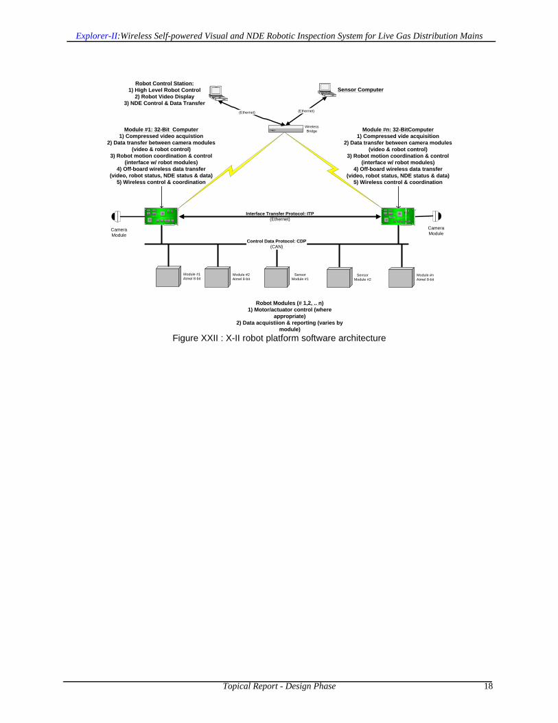
The design calls for an off-board Operator Control CPU, which communicates over custom antenna hardware using customized wireless protocols to the robot unit’s camera-module 32-bit SBC. All commands and data are passed in this fashion to and from the operator. The robot’s SBC handles all control and communications and video digitization tasks, as well as CAN-bus and power-bus control. A set of distributed 8-bit multiprocessors on different modules, provide all the power-support and motor-control as well as feedback and control message parsing. A set of (up to 2) sensor modules are responsible for all data-collection and -relaying over the CAN bus. All NDE-data is passed over the CAN bus to the 32-bit SBC, and over the wireless to the control CPU at the operator, from where it is forwarded over ethernet to the data-collection and -processing computer.
2.8 Software Architecture DesignThe software design mirrors the distributed multi-processor electronics architecture. Each module’s 8-bit processor is in charge of control and messaging running separate tasks via real-time kernel. The 32-bit SBC coordinates them all, running tasks that are responsible for video-processing, posture-control, communications, safety- and health-management and off-board communications and other house-keeping tasks. The 32-bit SBC operates under a reduced-build Linux OS, and due to its duplication (one in each camera-module) allows for splitting of the video-processing and communication tasks at will, based on a wired-ethernet peer-to-peer setup with a master/slave configuration (also implies system redundancy and antenna-gain diversity communications). A graphical rendition of the software architecture for the platform and overall system are shown in Figure XXII on page 18.
8-BIT ELECTRONICS•MOTOR CONTROL
•Drive•Leg Expand/Retract•Steering
•POWER SUPPORT•Conditioning•Charge/Discharge Monitor
•STATE FEEDBACK•Odometry•Inclination
DRIVE
STEER
SUPPORT
32-Bit ELECTRONICS•TELEOP CONTROL
•Video Imaging•Control Coordination•CAN Messaging•Wireless Relay
BATTY
SENSOR 1
SENSOR 2
CAMERA
CAMERA
CAN
SENSOR SYSTEM•SIGNAL CONTROL
•EM Coil •UT Xducers
•EMBEDDED CONTROL•CAN MESSAGING•SENSOR PROCESSING•DATA STORAGE
26 VDC
OPE
RA
TO
R C
ON
TR
OL
CPU
•GU
I & O
PER
ATO
R C
ON
TRO
L•N
DE
DA
TA R
OU
TIN
G
NDE DATA CPU
LAN
8-BIT ELECTRONICS•MOTOR CONTROL
•Drive•Leg Expand/Retract•Steering
•POWER SUPPORT•Conditioning•Charge/Discharge Monitor
•STATE FEEDBACK•Odometry•Inclination
DRIVEDRIVE
STEERSTEER
SUPPORTSUPPORT
32-Bit ELECTRONICS•TELEOP CONTROL
•Video Imaging•Control Coordination•CAN Messaging•Wireless Relay
BATTY
SENSOR 1
SENSOR 2
CAMERACAMERA
CAMERA
CAN
SENSOR SYSTEM•SIGNAL CONTROL
•EM Coil •UT Xducers
•EMBEDDED CONTROL•CAN MESSAGING•SENSOR PROCESSING•DATA STORAGE
26 VDC
OPE
RA
TO
R C
ON
TR
OL
CPU
•GU
I & O
PER
ATO
R C
ON
TRO
L•N
DE
DA
TA R
OU
TIN
G
NDE DATA CPU
LAN
Explorer-II:Wireless Self-powered Visual and NDE Robotic Inspection System for Live Gas Distribution Mains
Topical Report - Design Phase 18
Figure XXII : X-II robot platform software architecture
Module #1Atmel 8-bit
Control Data Protocol: CDP(CAN)
Robot Control Station:1) High Level Robot Control
2) Robot Video Display3) NDE Control & Data Transfer
WirelessBridge
(Ethernet)
Module #1: 32-Bit Computer1) Compressed video acquistion
2) Data transfer between camera modules(video & robot control)
3) Robot motion coordination & control(interface w/ robot modules)
4) Off-board wireless data transfer(video, robot status, NDE status & data)
5) Wireless control & coordination
Module #2Atmel 8-bit
Module #nAtmel 8-bit
SensorModule #1
Interface Transfer Protocol: ITP(Ethernet)
Robot Modules (# 1,2, .. n)1) Motor/actuator control (where
appropriate)2) Data acquistiion & reporting (varies by
module)
Module #n: 32-BitComputer1) Compressed vide acquisition
2) Data transfer between camera modules(video & robot control)
3) Robot motion coordination & control(interface w/ robot modules)
4) Off-board wireless data transfer(video, robot status, NDE status & data)
5) Wireless control & coordination
CameraModule
CameraModule
Sensor Computer
(Ethernet)
SensorModule #2

Explorer-II:Wireless Self-powered Visual and NDE Robotic Inspection System for Live Gas Distribution Mains
Topical Report - Design Phase 19
3.0 Sensor-Module SpecificationsThe sensor module specifications were drafted and finalized and are summarized in key tables and interface drawings related to the mechanical, electrical and software specifications detailed in this section.
3.1 Overall RequirementsThe following tabular representation was agreed upon to capture all the main requirements of import to any NDE sensor module requiring to be interfaced to the X-II platform:
Table 1-4 : Sensor Module Interface Specifications
The sensor module specifications cover the number, size and weight of same, as well as their separation and articulation. The system has to operate under different modes with distinct power-draw limitations. Power is off the same robot-bus and communications are over a CAN bus. Off-board NDE data-transfer between the robot control CPU operated by the operator and the data-operator is over wired/wireless ethernet. Wiring pass-throughs are required and specified in terms of number and gauge. Special care will need to be given to the potential of non-centricity during operation (up to 0.5”), vibrations during operation and the need to EMI-shield pass-through wiring to avoid noise-introduction.
PARAMETER CONSENSUS# Modules < int(2)
Size 5” L x 4” DIA cylinderWeight < 10 lbsSpacing 23 inches
Angular Motion-Range 77o - 80o
System Data on Bus Inclinometer, system time, odometerCommunications Bus 1 MHz CAN (2.0b)
Protocol CMU-custom, TTP, 32 bitPower Bus Specs 26 VDC nominal
Deploy / Retract: 30 W for 2 minutes - (1.2 A @ 24 V dc)Scanning: 24W continuous - (1.0 A @ 24 VDC)
Idle: 12W continuous (when not scanning) - (0.2A @ 24 VDC)IDLE: < 50 k bits/sec
DATA DUMP: < 450 k bits/secINTEARCT: < 150 k bits/sec
Sensor-Drag < 1lbf totalOff-board NDE data transfer Ethernet (802.11)
Inter-module Wiring 4 TP; 28 AWGProtocol Documentation Approved by all
Vibration Isolation Standoff & Absorption tolerant
EMI Protection Motor/Coil EMI to be expected; Isolation responsibility of ea. partyPass-thru shielding EMI shielding by Sensor-Providers
Data Storage / Transfer Specs
Power Draw Specs

Explorer-II:Wireless Self-powered Visual and NDE Robotic Inspection System for Live Gas Distribution Mains
Topical Report - Design Phase 20
3.2 Mechanical InterfaceThe volume and mechanical and wiring interface diagram were clearly defined, as were the interconnections (via pigtail wiring) and are reflected in the image of Figure XXIII:
Figure XXIII : Mechanical size and shape specifications for the sensor module
3.3 Sensor Wiring SchematicThe sensor wiring diagram required to be followed by the sensor module was also developed and is depicted in Figure XXIV:
Figure XXIV : Sensor module wiring interface diagram requirements

Explorer-II:Wireless Self-powered Visual and NDE Robotic Inspection System for Live Gas Distribution Mains
Topical Report - Design Phase 21
3.4 CAN Bus Isolation SchematicIn order to avoid any bus-crashes and -hogging’, a communication-bus isolation schematic was provided to ensure the availability and up-time of the bus on the robot - it is depicted in Figure XXV:
Figure XXV : CAN bus sensor module isolation requirement schematic

Explorer-II:Wireless Self-powered Visual and NDE Robotic Inspection System for Live Gas Distribution Mains
Topical Report - Design Phase 22
IV. PRE-PROTOTYPING & EXPERIMENTATION
As part of the prototype testing activities carried out to support the design phase, CMU engaged in several critical activities in order to reduce technical risk and better guide the design in key areas listed below.
1.0 Pressure TestingAll critical electronic components were tested under pressure in a setup rated to 750 psig, by teaming with an outside contractor. All components, including OEM PCBs were found to be tolerant to those pressures, excluding the video imager, which will have to be housed and pressure-protected. An image of the pressure test setup is shown in Figure XXVI on the right.
Figure XXVI : Pressure test-chamber system
2.0 Computing-System testingThe 32-bit OEM computer was acquired and tested in terms of its main I/O and the OS usability and CAN connectivity and wired/wireless networking hardware. It was discovered that CAN-compatibility 2.0b was not achievable, requiring all systems to be set for 1.1 compatibility. An image of the hardware is shown in Figure XXVII.
Figure XXVII : 32-bit SBC OEM components used in testing
3.0 Illumination System TestingA new type of higher-efficiency white LED was tested, using individual units, mounting them to a prototype nose-cone section from X-I and performing illumination (voltage, current LUX, etc.) experiments inside a 6- and 8-inch diameter pipe (see inset Figure XXVIII).
Figure XXVIII : Higher efficiency white LED illuminator test setup

Explorer-II:Wireless Self-powered Visual and NDE Robotic Inspection System for Live Gas Distribution Mains
Topical Report - Design Phase 23
In addition, a prototype LED illumination ring was built and tested in a pipe to ascertain the power, heating and illumination achievable with the new LEDs and system design. An image of the setup is shown to the right in Figure XXIX.
Figure XXIX : Prototype LED illuminator ring and test-camera setup
4.0 Arm JigA prototype test-jig for calibrating and testing strain-gauge based leg-force sensors was built and assembled and strain measurements taken to feed into the control algorithms to control bracing and contact forces. An image of the setup is shown on the right in Figure XXX.
Figure XXX : Drive-arm strain-gauge and leg-expand/-collapsetest-jig
5.0 Prototype Electronics for testingA suite of preliminary PCBs was built and is undergoing testing for electrical functionality and preliminary software development. Circuits for the nose/camera and drive and steering modules have been developed and are shown in Figure XXXI.
Figure XXXI : Prototype module control PCBs
6.0 Pre-prototype partial robot trainFor more in-depth software and electronics testing, a preliminary drive-, steering and nose-section were built and interfaced to the electronics and bench-top supplies for evaluation and software testing. It will be used by developers until the final robot is assembled and ready for software porting, integration and debugging. An image of the setup is shown in the inset image of Figure XXXII.
Figure XXXII : Pre-prototype robot-train section(s)assembly

Explorer-II:Wireless Self-powered Visual and NDE Robotic Inspection System for Live Gas Distribution Mains
Topical Report - Design Phase 24
V. ACKNOWLEDGEMENTS
The design of Explorer-II has been made possible via a contract to CMU, funded by NETL/DoE (DE-FC26-04NT42264) and co-funded by NGA (Contract # M2003-009).

Explorer-II:Wireless Self-powered Visual and NDE Robotic Inspection System for Live Gas Distribution Mains
Topical Report - Design Phase 25
VI. REFERENCES
[1] Ives, G., Jr., “Pipe Ruptures”, PipeLine & Gas Industry Journal, Vol. 83, No.9, Houston, TX[2] Staff Report, “New Optical methane detector improves gas leak surveys”, PipeLine & Gas Industry Journal,
September 2000[3] Porter, C., Pittard, G., “Magnetic Flux Leakage Technology for Inspecting ‘Live’ Gas-Distribution Mains”, GTI
Technical Report # GRI-99/0199, Oct. 1999, Chicago, IL[4] Schempf, et al., “Robotic Repair System for Live Distribution Gasmains”, Field and Service Robotics Confer-
ence., FSR 2001, June 11 - 13, Helsinki, Finland.[5] Guidance Manual for Operators of Small Natural Gas Systems, US Department of Transportation, Research
and Special Programs Administration, August 1997.[6] Schempf, et al., “GRISLEE: Gasmain Repair and Inspection System for Live Entry Environments”, IEEE Inter-
national Journal of Robotic Research, pending publication in 2004.[7] Schempf, H. and Vradis, G., “Explorer: Long-Range Untethered Real-Time Live Gas Main Inspection System”,
Natural Gas Technologies II Conference, Feb. 8 - 11, 2004, Phoenix, AZ[8] Cremer, C. D., and D.T. Kendrick. “Case Studies of Uses of the Pipe Explorer™ System“, Spectrum '98, Inter-
national Conference on Decommissioning and Decontamination and on Nuclear and Hazardous Waste Manage-ment, Denver, CO, September 13-18, 1998.

Explorer-II:Wireless Self-powered Visual and NDE Robotic Inspection System for Live Gas Distribution Mains
Topical Report - Design Phase 26
IX. APPENDICES
1.0 Gas Pipeline Robot State-of-the-Art Review
1.1 Introduction - Pipe RobotsInternal pipe inspection and maintenance are not new concepts in such industries as sewer and water maintenance as well as transmission pipelines for oil and gas. Such systems typically are an integration of mechanical, electrical and software subsystems, supporting one or more sensory payloads for measuring the pipe’s overall state and structural integrity (corrosion, ovality, etc.). One of the main subsystems in such inspection systems is the locomotor or mobile platform that carries the sensing and explorative end of the tool. This is the area this report will focus on as part of the state-of-the-art review contained in this report, by illustrating technical advances and deficiencies, by way of seminal platform examples (whether fielded, prototypes or in the design-stage). The intent will be to help support technology-developers and decision-makers in understanding how and where to provide technology innovation and where to allocate ones resources to see technical advances realized.
1.2 BackgroundThe above-mentioned application-areas are discussed in brief detail below by way of an overview and a few of the salient examples and a comparative table condensing the comparative descriptors that one might use into a single graspable location. There are however substantial differences and presumptions that will remain to be clarified in order to understand the gradation in terms of capabilities and applications in this arena.1.2.1 Water and Sewer MainsThis area is not intended to be elaborated on in any depth as part of this report. It is however worth noting that in-pipe robots, mostly self-powered units, have and are seeing their largest volume applications in this arena. All of these systems rely on a power- and (push-)pull tether to provide power and communications to the robot, and return information to the user. Most of this information is raw video-data, but can also include acoustic as well as laser-caliper dimensioning data. Efforts have been made in the past to also make these systems more autonomous by providing on-board battery power and ‘cutting’ the tether and relying on on-board smart software and guidance/navigation/imaging sensors to handle in-pipe locomotion decisions. However, due to the bulk and shear linear footage of water- and sewer-pipes in the world, and the relatively low barrier to entry (cost, operational infrastructure and relatively low operational hazard-level), this industry has seen substantial growth in the last decade and will continue to be the largest market for in-pipe robots in terms of revenue for near foreseeable future.Some of the more salient images of the state-of-the-art in water and sewer pipe inspection and repair systems are depicted in the figure below:
KA-TE
PearpointBeaverBlackHawk
KURT I

Explorer-II:Wireless Self-powered Visual and NDE Robotic Inspection System for Live Gas Distribution Mains
Topical Report - Design Phase 27
1.2.2 Oil- and Gas PipelinesThis application area has seen substantial work in the past 20 years. Most of the past and current effort has focussed on using passive flow-powered (pigs) platforms to carry an ever-improving array of sensors for integrity evaluation. New efforts in the past few years has begun to also look at actively powered platforms to access the unpiggable sections of these transmission mains. Both of these areas are covered further below.1.2.2.1 Transmission Mains - Pipe PigsThere are basically two types of pipe pigs; the simple mechanical version that is used for cleaning and flow passage surveys; and the more complex version that integrates the basic platform with other sensor-based elements intended for pipe inspection. These elements range from simple mechanical calipers to advanced electronics to optical based data storage. The evolution of the sensor-based platforms has resulted in a family of inspection tools commonly referred to as Smart Pigs. The simple mechanical pig is basically a piston moving through the pipe, being powered by the fluid flow and the associated pressure drop across the seals. Pigs require the internal pipe diameter to remain relatively constant and the pipe runs to be straight or only gradually curving to guarantee ‘safe’ passage. Since current sensor technologies accuracy depends on surface cleanliness (mostly), cleaning is accomplished through the mounting of bristle brushes and/or the use of hardened surfaces around the circumference of the pressure seals. The use of these types of pigs does require a means for removing the debris that accumulates in front of the pig as it moves through the pipeline; that is why an inspection run is typically preceded by one or cleaning-pig runs. A modern Smart pig is quite sophisticated in both configuration and inspection capability. Smart pigs include on-board power supplies, data recorders and storage, and sophisticated NDE sensors to measure pipe wall defects. Magnetic flux leakage (MFL) has been the most popular NDE technique employed on pigs. However, ultrasonic, eddy current and acoustic sensors are also commercially available for Smart pigs. A collection of such cleaning and sensing pigs offered by the industry leaders1, are depicted in the figure below:
There are many physical obstacles within typical transmission pipelines that have (in the past) curtailed and/or restricted the use of these Smart pigs, many of which have seen technology improvements over the years. Despite these advances though, many deficiencies (physical and flow obstacles) remain with the current technology that will prevent the use of these devices in many miles of existing transmission pipelines, especially those belonging to local gas distribution companies.
1. Integrated Full-Service Companies: Rosen, TDW, GE/PII, TuboScope, Baker-Hughes, CPIG, InvoDane, Enduro, etc.
Rosen
GE/PII
TDW

Explorer-II:Wireless Self-powered Visual and NDE Robotic Inspection System for Live Gas Distribution Mains
Topical Report - Design Phase 28
1.2.2.2 Oil- and Gas-Wells - Tethered & Autonomous RobotsThe use of robots to perform downhole operations (E&P: Exploration & Production - whether oil or gas wells) has been under consideration for about 10 years. Existing pieces of equipment are exclusively tethered by slickline (simple cable) or coiled-tubing deployed. There are hybrids such as the WellTec system that is powered over a cable, and the iTRobotics system which is autonomous but is only used for inspections of coiled-tubing itself. Prototypes such as Shell’s Bore-shuttle and Baker-Hughes downhole robot do exist but have not yet seen full commercialization - these systems have no link to the surface and operate completely autonomously and using on-board power while travelling up and down the casing in an oil/gas well. Images of these systems are shown in the figure below:
1.2.2.3 Distribution Mains - Stick-Cameras In terms of systems that have been used in live gas mains, particularly lower-pressure (< 100 psig) distribution mains, only a few video-inspection systems have come to the commercial market. they are able to be pushed/pulled into place using a tensile/power/data cable and are launched into a live main using specialty fittings and deployment systems. They provide only video but are commonly used for rapid inspection of critical/emergency areas. They vary in size, but the inspection-diameters of the pipes in question range from 4 to 10 inches in diameter and are almost exclusively in use in the natural gas industry. Three of the main systems in use today are depicted in the image below:
1.2.2.4 Distribution Mains - Pipe CrawlersIn the application of lower-pressure distribution mains for natural gas, several systems have been prototyped and fewer deployed for real-world inspection and repair in live natural gas mains. These
iTRobotics
Baker-HughesAI-Shell
WellTec
Slick
Aries
ULC
GBS

Explorer-II:Wireless Self-powered Visual and NDE Robotic Inspection System for Live Gas Distribution Mains
Topical Report - Design Phase 29
systems are characterized by both tetherless and tethered operations over substantial long distances under live conditions. Advantica (R&D division of British gas) demonstrated the ability to perform RFEC inspection of steel pipes with a segmented robot, yet it has not yet been field-hardened. The FM PipeMouse is a tethered inspection system capable of traversing sharp geometries, yet it never was field-deployed. Explorer is the first robot to perform truly untethered real-time video inspection of live gas mains in real time while also being capable of traversing bends, Ts, junctions and vertical pipe-sections. A collage of these inspection systems is given in the figure below:
Other existing systems in use by the gas distribution industry revolve around pipe-inspection and repair. The two most notable ones are CISBOT and GRISLEE. The former is a tethered system capable of inspecting and repairing (via sealant-injection) cast-iron bell-and-spigot joints. The latter is a modular system to perform a visual and NDE MFL inspection, and perform an in-situ repair using composite repair sleeves - all while being deployed into and out of a main under live conditions using a coiled-tubing push-pull tether with internal power and data conductors. These two systems are depicted below:
1.2.2.5 Other applicationsAnother noteworthy locomotion platform under development is the revival of the PipeMouse as the RoboScan platform for use in unpiggable transmission mains. This system will be self-powered and using autonomous control, while it scans the large-diameter transmission main for pipe-wall degradation using NDE sensor technologies.
Advantica
FM PipeMouseExplorer
CISBOTGRISLEE
RoboScan

Explorer-II:Wireless Self-powered Visual and NDE Robotic Inspection System for Live Gas Distribution Mains
Topical Report - Design Phase 30
1.3 Platform ComparisonThe comparison-table depicted on the next page, attempts to provide detail on the different platforms locomotion characteristics as well as provide common and differentiating features amongst them.In terms of pure locomotion, it seems clear that there are fully-tethered short-range system-solutions, as well as (mostly) untethered long-range systems capable of both video as well as NDE (development only) inspection. For those systems where power is provided on-board, using rolling locomotion is a clear preference. There seem to be different approaches to provide for traction but all rely on compressive-force against the pipe. Different geometries to achieve pipe-adaptation have been implemented, as well as different types of articulation and steering joints, all the way from purely passive, to fully articulated/powered. Geometries are clearly pipe-diameter dependent, as well as what types of obstacles they need to be able to handle such as sharp bends, elbows, plug-valves, etc. With the exception of one, all systems provide for real-time data through a dedicated copper or fiber-link/-tether. Even though on the drawing-board, there seems to be a clear lack of long-range inspection capability for both small and large diameter pipe-sizes under low and high pressure conditions, utilizing more than just video inspection but also coupling it with NDE-inspection.To achieve inspection-ranges in the miles and perform the inspection in real time and under teleoperated or supervised/autonomous fashion, will require technology advancement in key areas such as battery-power and -recharge, communications, sensor-miniaturization and reliable control/autonomy software. The platform geometries and ability to locomote provides for different solutions which are typically driven by geometrical constraints as well as innovative preference depending on the development outfit as well as any relevant real-world deployment experience they may have accumulated over time - there is however no substantially superior architecture, locomotion or integration design that has yet been proven through field-deployments to be superior to its competitors, the main reasons being a real lack of competing varieties of platforms as well as a lack of real-world deployment data for all existing platforms or those still under development.

Topical Report - Design Phase 31
Explorer-II:Wireless Self-powered Visual and NDE Robotic Inspection System for Live Gas Distribution Mains
Pipe
Mar
ket S
egm
ent
1
Tech
nolo
gy M
atur
ity2
Des
ign
Arc
hite
ctur
e3
Obs
tacl
e H
andl
ing
4
Loco
mot
ion
Mod
e/Ty
pe
Rep
air C
apab
ility
Insp
ectio
n C
apab
ility
Sens
or T
ype(
s)6
Teth
ered
Pow
er &
Com
ms
Type
7
Ran
ge p
er la
unch
[in] [Y/N] [Y/N] [Y/N] [ft]
Civil Infrastructure
Water / Sewer Mains
Various BlackHaw k, PearPoint, Beaver, KA-
TE, Innuktun, etc.
Many - see previous W/S Comm M, O
SPO, MC
FW, FT, PPT
Y Y V, UT YLV, TL < 200
Pipelines Pigs
Various Rosen, GE/PII, TDW, TuboScope,
CPIG, B.Hughes, Halliburton, Enduro, etc.
Many - see previous GT Comm M, S
SPO, MC, TSB
FP N Y All; no V N BS,
NL Miles
Bore-Shuttle AI/Shell E&P Prot M SPO, MC
FP, AW N Y TBD;
no V N BS, A Miles
Slick-Tool BakerHughes E&P Comm S SPO, MC PPT N Y MFL,
EC Y LV Miles
WellTractor WellTec E&P Comm M SPO, MC
AW, PPT N Y O Y LV,
TL Miles
WellBot iR/Halliburton E&P Field M,S SPO, MC FW N Y U N BS, A U
Coiled-Tube InspectorBot iTRobotics E&P Field S SPO, MC FW N Y MFL,
EC N LV, NL
Mile+, U
PipeCam GBS GD Comm M SPO PPT N Y V Y LV, TL <1000
GasCam Aries GD Comm M SPO, MC PPT N Y V Y LV,
TL <200
HP Gas Camera ULC GD Comm M SPO, MC PPT N Y V Y LV,
TL <200
RFEC Inspector Advantica GD Field S SPO, MC FW N Y EC N BS, U U
PipeMouse FosterMiller GD Prot S All; no V AW N Y V Y BS,
TL U
Explorer CMU/NGA GD Field S All AW N Y V N BS, W >1000
CISBOT ConEd GD Comm M SPO, MC PPT Y Y V Y LV,
TL <250
GRISLEE CMU/MEI/GTI GD Field S SPO, MC PPT Y Y MFL,
V Y LV, TL <1000
RoboScan FM/NGA/DoE GT CAD S U AW N Y TBD U BS, TL U
1
2
34
5
67
Video (V), Ultrasonic (UT), Magnetic Flux Leakage (MFL), RF Eddy Current (EC), EMAT, Caliper-Tool (CT), Other (O), Unknow n (U), TBDPOWER: Line-Voltage (LV), Battery Supply (BS) COMMS: Tether-Link (TL), Wireless (W), Autonomous (A), No-Link (NL)
Monolithic (M), Segmented (S), Other (O)Straight-Pipe-Only (SPO), Minimal Curvature (MC), Tights Smooth Bends (TSB), Sharp bends Elbow s and Ts (SBET), Verticals (V)
MARKET CATEGORY SYSTEMSUPPLIER
OR VENDOR
Oil & Gas Wells
Exploration &
Production (E&P)
Pipe-Cameras
Gas Pipelines
Water (W), Sew er (S), Gas Distribution (GD), Gas Transmission (GT)CAD (Low ), Prototype (Lab only), Fielded (Real-w orld Proven), Commercial (Mature, Reliable & Cash-Generator)
Pipe-Crawlers
Flow -Pressure (FP), Fixed-Wheel Craw ler (FW), Fixed-Tracked (FT), Articulated-Wheel (AW), Push-Pull-Tether (PPT)

Explorer-II:Wireless Self-powered Visual and NDE Robotic Inspection System for Live Gas Distribution Mains
Topical Report - Design Phase 32
1.4 References 1. www.pearpoint.com 2. KaTe System AG; http://www.ka-te-system.com/html/homee.html 3. http://www.foster-miller.com/t_robotics.htm 4. “GRISLEE: Gasmain Repair & Inspection System for Live Entry Environments“,
CLAWAR'01 Special Issue of the International Journal of Robotics Research, March-April, 2003, Vol. 22, Nos 3 and 4.
5. “Explorer: Untethered Real_time Gas Main Assessment Robot System“, 1st International Workshop on Advances in Service Robotics, ASER’03, Bardolino, Italy, March 13-15, 2003
6. http://www.ariesind.com/gascam.html 7. http://itrobotics.ath.cx/Products/Products.htm 8. http://www.advantica.biz/ 9. http://www.ulcrobotics.com/ 10.http://www.maurertechnology.com/Engr/Products/MFL.asp 11.www.netl.doe.gov/scngo/Reference%20Shelf/ tsa/tsa-videoinspect-0202_1.PDF 12.www.bakerhughes.com/pmg 13.CISBOT - Company: ConEd – Enbridge Product: Cisbot: Contact: Terry
Whitehead, Enbridge Contact Phone Number: 416-496-7147 14.http://www.nygas.org/M-2002-015.htm 15.http://www.welltractor.com/ 16. “Method and System for moving equipment into
and through an underground well”, Pat.# 6,675,888 17.http://www.bakerhughes.com/bot/service_tools/index.htm 18.www.tdwilliamson.com 19.www.roseninspection.net 20.http://www.gepower.com/prod_serv/serv/pipeline/en/index.htm 21.www.blackhawk-pas.com 22.http://www.ais.fraunhofer.de/BAR/kurt.htm 23.http://www.netl.doe.gov/publications/press/2004/tl_oilgas_bbfa.html 24.http://www.netl.doe.gov/scngo/Natural%20Gas/Projects_n/TD&S/T&D/
T&D_C_41645RobotPlatform.html