Embed Size (px)
Citation preview
International Journal of Advanced Research in Electronics and Communication Engineering (IJARECE)
Volume 4, Issue 4, April 2015
ISSN: 2278 – 909X All Rights Reserved © 2015 IJARECE 834
Abstract— Turbo Decoder plays a significant role in
today’s 4G networks. This work focuses on Encoding and
Decoding process by using Turbo Decoding techniques.
The Maximum A Posteriori (MAP) probability decoders,
which are intrinsic building-blocks of parallel turbo
decoders. The Logarithmic –Bahl –Cocke–Jelinek–Raviv
(LBCJR) algorithm used in MAP decoders, It presents
with an ungrouped backward recursion technique for the
computation of backward state metrics. Unlike the
conventional decoder architectures, this technique can be
extensively pipelined and retimed to achieve higher clock
frequency. Additionally, the state metric normalization
technique employed in the design of an
Add-Compare-Select-Unit (ACSU) has reduced critical
path delay of decoder architecture and we can replace
normal adder into Carry look-ahead adder it will
increase the speed of LTE and LTE-advanced.
Index Terms—ACSU, CE, CLA, LBCJR algorithm, LTE,
MAP, Trellis Graph, Turbo Decoder.
I. INTRODUCTION
LTE, an abbreviation for Long-Term Evolution,
commonly marketed as 4G LTE, is a standard for wireless
communication of high-speed data for mobile phones and
data terminals. It is based on the GSM/EDGE and
UMTS/HSPA network technologies, increasing the
capacity and speed using a different radio interface
together with core network improvements. The standard
is developed by the 3GPP (3rd Generation Partnership
Project).
LTE is the natural upgrade path for carriers with both
GSM/UMTS networks and CDMA2000 networks. The
different LTE frequencies and bands used in different
countries will mean that only multi-band phones will be
able to use LTE in all countries where it is supported.
Although marketed as a 4G wireless service, LTE (as
specified in the 3GPP Release 8 and 9 document series)
does not satisfy the technical requirements the 3GPP
consortium has adopted for its new standard generation,
and which were originally set forth by the ITU-R
organization in its IMT-Advanced specification.
However, due to marketing pressures and the significant
Manuscript received Apr 10, 2015.
Sangeetha V, ME(VLSI Design), Anna University/ Sri Shakthi Institute
of Engineering and Technology, Coimbatore,India,
Lalithambigai M, Asst. professor of ECE Dept,/ Sri Shakthi Institute of
Engineering and Technology, Coimbatore,India,
advancements that WiMAX, HSPA+ and LTE bring to
the original 3G technologies, ITU later decided that LTE
together with the aforementioned technologies can be
called 4G technologies. The LTE Advanced standard
formally satisfies the ITU-R requirements to be
considered IMT-Advanced. To differentiate LTE
Advanced and WiMAX- Advanced from current 4G
technologies
3GPP-LTE-Advanced standard has appeared with the aid of powerful technique like carrier aggregation. This standard supports a peak data rate of 1 Gbps specified by the International –Telecommunication –Union -Radio communication -Sector (ITUR) for the International -Mobile Telecommunications -Advanced (IMT-A), which is also referred as fourth-generation (4G) [3]. Eventually, enhanced use of multi-antenna techniques and support for relay nodes in the LTE-Advanced air-interface have made its new releases capable of supporting peak data rate(s) of 3 Gbps milestone. For reliable and error- free communication in these recent standards, turbo code has been extensively used because it delivers near-optimal bit-error-rate (BER) performance [5]. However, the iterative nature of turbo decoding imposes adverse effect which defers turbo decoder from achieving high-throughput benchmarks of the latest wireless communication standards. On the other hand, extensive research on the parallel architectures of turbo decoder has shown its promising capability to achieve higher throughput, albeit, at the cost of large silicon-area [6]. Parallel turbo decoder contains multiple Maximum A Posteriori (MAP) probability decoders, contention-free interleavers, memories and interconnecting networks. Maximum achievable
throughput of such P radix decoder with radix- MAP
decoders for a block length of N and a sliding window size of M is given as
where Z = N/M, F is a maximum operating clock frequency, 𝜌 represents a number of decoding iterations
, is a pipeline delay for accessing data from
memories to MAP decoders, is a pipeline delay for
writing extrinsic information to memories, and is a
decoding delay of MAP decoder [7]. This expression
Exploiting A New Turbo Decoder Technique For
High Performance LTE In Wireless
Communication
Sangeetha V, Lalithambigai M
International Journal of Advanced Research in Electronics and Communication Engineering (IJARECE)
Volume 4, Issue 4, April 2015
ISSN: 2278 – 909X All Rights Reserved © 2015 IJARECE 835
suggests that the achievable throughput of parallel turbo decoder has dominant dependencies on number of MAP decoders, operating clock frequency and number of decoding iterations. Thereby, valuable contributions have been reported to improve these factors. An implementation of parallel turbo decoder which uses retimed and unified radix MAP decoders, for Mobile
WiMAX (worldwide-interoperability- for-microwave-access) and 3GPP - LTE standards, is presented in [8]. Similarly, parallel architecture of turbo decoder with contention-free interleaver is designed for higher throughput applications. For 3GPP-LTE standard, reconfigurable and parallel architecture of turbo decoder with a novel multistage interconnecting network. Recently, a peak data rate of 3GPP-LTE standard has been achieved by parallel turbo decoder. Subsequently, a processing schedule for the parallel turbo decoder has been proposed to achieve 100% operating efficiency, high throughput parallel turbo decoder based on the algebraic-geometric properties of Quadratic-Permutation-Polynomial (QPP) interleaver has been proposed. An architecture incorporating a stack of 16 MAP decoders with an optimized state -metric initialization scheme for low decoder latency and high throughput. Another contribution which includes a very high throughput parallel turbo decoder for LTE-Advanced base station. Recently, a novel hybrid decoder-architecture of turbo Low-Density-Parity-Check (LDPC) codes for multiple wireless communication standards. Based on the comprehensive overview of recent standards for wireless communication, primary motive of our research is to conceive an architecture of turbo decoder for high throughput application. We have focused on an improvement of maximum clock frequency (F) which eventually improves an achievable throughput of parallel turbo decoder from (1). So far, no work has reported parallel turbo decoder that can achieve higher throughput beyond 3Gbpsmilestone targeted for the future releases of 3GPP-LTE-Advanced. 1) We propose a modified MAP-decoder architecture based on a new ungrouped backward recursion scheme for the sliding window technique of the Logarithmic- Bahl–Cocke–Jelinek–Raviv (LBCJR) algorithm and a new state metric normalization technique. The suggested techniques have made provisions for retiming and deep-pipelining in the architectures of the State-Metric-Computation-Unit (SMCU) and MAP decoder, respectively, to speed up the decoding process. 2) As a proof of concept, an implementation in 90nm CMOS technology is carried out for the parallel turbo decoder with 8 radix-2 MAP-decoders which are integrated with memories via pipelined interconnecting networks based on contention-free QPP interleavers. It is capable of decoding 188 different block lengths ranging from 40 to 6144 with a code-rate of 1/3 and achieves more than the peak data rate of 3GPP-LTE. We have also carried out synthesis-study and postlayout simulation of a parallel turbo decoder with 64 radix-2 MAP decoders that can achieve the milestone throughput of 3GPP-LTE-Advanced.
3) In this paper, we can replace normal adder into Carry Look-Ahead Adder[12]. In this CLA is used to increase the speed of the circuit in this 3GPP-LTE-Advanced wireless communication standards.
II. TRANSMITTER AND RECEIVER
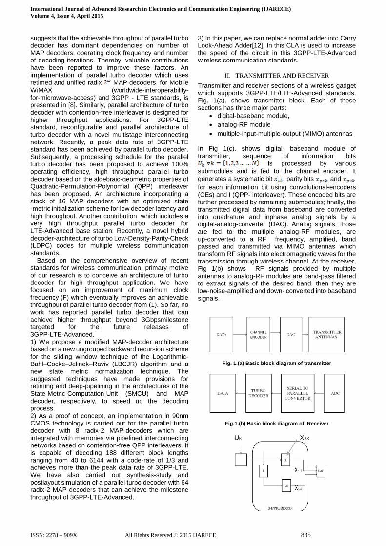
Transmitter and receiver sections of a wireless gadget which supports 3GPP-LTE/LTE-Advanced standards. Fig. 1(a). shows transmitter block. Each of these sections has three major parts:
digital-baseband module,
analog-RF module
multiple-input-multiple-output (MIMO) antennas
In Fig 1(c). shows digital- baseband module of transmitter, sequence of information bits
is processed by various
submodules and is fed to the channel encoder. It generates a systematic bit , parity bits and
for each information bit using convolutional-encoders (CEs) and I (QPP- interleaver). These encoded bits are further processed by remaining submodules; finally, the transmitted digital data from baseband are converted into quadrature and inphase analog signals by a digital-analog-converter (DAC). Analog signals, those are fed to the multiple analog-RF modules, are up-converted to a RF frequency, amplified, band passed and transmitted via MIMO antennas which transform RF signals into electromagnetic waves for the transmission through wireless channel. At the receiver, Fig 1(b) shows RF signals provided by multiple antennas to analog-RF modules are band-pass filtered to extract signals of the desired band, then they are low-noise-amplified and down- converted into baseband signals.
Fig. 1.(a) Basic block diagram of transmitter
Fig.1.(b) Basic block diagram of Receiver
UK XSK
International Journal of Advanced Research in Electronics and Communication Engineering (IJARECE)
Volume 4, Issue 4, April 2015
ISSN: 2278 – 909X All Rights Reserved © 2015 IJARECE 836
Fig.1.(c) Tx- Digital-Baseband Module
Subsequently, these signals are sampled by Analog-Digital-Converter (ADC) of the digital-baseband module, where various submodules process such samples and are fed to the soft-demodulator. It generates a priori logarithmic-likelihood-ratios (LLRs)
, and for the transmitted systematic and
parity bits, respectively, and are fed to
turbo decoder via serial-parallel converter. Turbo decoders work on graph based approach and are parallel concatenation of MAP decoders, as shown in Fig. 1(a). Basically, the MAP decoder uses BCJR algorithm to process input a priori LLRs and then determine
the values of a posteriori LLRs for the transmitted bits.
Extrinsic information values are computed as
(2)
and
(3)
where and are a posteriori LLRs from
MAP decoders; and are de-interleaved and
interleaved values, respectively, of the extrinsic information.
As shown in Fig.1(a), the values of extrinsic information are
iteratively processed by MAP decoders to achieve
near-optimal BER performance. Finally, a posteriori LLR
values, those are generated by turbo decoder, are processed
by rest of the baseband submodules. Ultimately, a sequence of
decoded bits is obtained, as shown in Fig. 1(a). On the
other hand, conventional BCJR algorithm for MAP decoding
includes mathematically complex computations. It delivers
near-optimal error-rate performance at the cost of huge
memory and computationally intense VLSI
(very-large-scale-integration) architecture, which imposes
large decoding delay. These shortcomings have made this
algorithm inappropriate for practical implementation.
Logarithmic transformations of miscellaneous
mathematical equations involved in BCJR algorithm have
scaled down the computational complexity as well as
simplified its architecture from an implementation
perspective, and such procedure is referred as
logarithmic-BCJR (LBCJR) algorithm. Furthermore, huge
memory requirement and large decoding delay can be
controlled by employing sliding window technique for
LBCJR algorithm. This is a trellis-graph based decoding
process in which N stages are used for determining a
posteriori LLRs
where each stage comprises of trellis states. LBCJR
algorithm traverses forward and backward of this graph to
compute forward as well as backward state
metrics, respectively, for each trellis state such that k ε N and
i ε . As shown in Fig. 1(c), for states and , forward
and backward state metrics during their respective traces are
computed as
(4)
respectively, where a logarithmic approximation which
simplifies mathematical computations of BCJR algorithm.
Based on max-log-MAP approximation, this function
operates as
.
Similarly, log-MAP approximation computes as
.
III. PROPOSED THECNIQUES
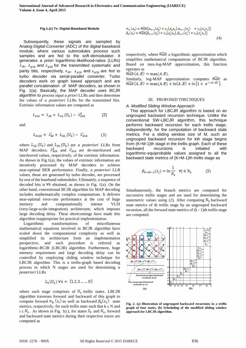
A. Modified Sliding Window Approach This approach for LBCJR algorithm is based on an ungrouped backward recursion technique. Unlike the conventional SW-LBCJR algorithm, this technique performs backward recursion for each trellis stage, independently, for the computation of backward state metrics. For a sliding window size of M, such an ungrouped backward recursion for kth stage begins from (K+M-1)th stage in the trellis graph. Each of these backward recursions is initiated with logarithmic-equiprobable values assigned to all the backward state metrics of (K+M-1)th trellis stage as
Simultaneously, the branch metrics are computed for
successive trellis stages and are used for determining the
statemetric values using (2). After computing backward
state metrics of th trellis stage by an ungrouped backward
recursion, all the forward state metrics of (k - 1)th trellis stage
are computed.
Fig. 2. (a) Illustration of ungrouped backward recursions in a trellis
graph of four states. (b) Scheduling of the modified sliding window
approach for LBCJR algorithm.
International Journal of Advanced Research in Electronics and Communication Engineering (IJARECE)
Volume 4, Issue 4, April 2015
ISSN: 2278 – 909X All Rights Reserved © 2015 IJARECE 837
It is to be noted that the forward recursion starts with an
initialization at k=0 such that
(6)
Fig. 2(a) illustrates the suggested ungrouped backward recursions for LBCJR algorithm with a value of M=4. It shows the computation of backward statemetrics for k=1 and k=2 trellis stages. First ungrouped backward recursion (denoted as u = 1) starts with the computation of using the initialized backward state metrics
from trellis stage. Thereafter, is computed
using ; finally, an effective set of backward
state metric , which is then used in the
computation of a posteriori LLR for k=1 trellis stage, is
obtained using the value of . Similarly, such
successive process of second ungrouped backward recursion (u=2) is carried out to compute an
effective-set of for k=2 trellis stage, as shown
in Fig.2(a). In this suggested-approach, time-scheduling of various operations to be performed for the computation of successive a posteriori LLRs is schematically presented in Fig. 2(b). This scheduling is illustrated for M=4, where the trellis stages and time intervals are plotted along y-axis and x-axis respectively. An ungrouped backward recursions begin from the time interval to ts because the branch
metrics required for these recursions are available from this interval onward. Thereby, referring Fig. 2(b), operations performed from this interval onward are systematically explained as follows. • : A first ungrouped backward recursion (denoted by
u=1 ) begins with the computation of which
uses the initialized backward state metrics from trellis stage. Since, this backward recursion is performed to computean effective-set of backward state metrics for k=1, it is started from (k+M-1)=4th trellis stage. • : A consecutive-set is computed for the
continuation of first ungrouped backward recursion. Simultaneously, a second ungrouped backward recursion starts from the initialized trellis stage k=5 with the computation of a new-set .
• : First ungrouped backward recursion ends in this
interval with the computation of effective-set
for k-1 trellis stage. In parallel, second ungrouped backward recursion continues with the computation of consecutive- set . Similarly, a new-set
is computed and it marks the start of third
ungrouped backward recursion. Initialization of all the forward state metrics of set is also carried out.
• : An effective-set is obtained with the
termination of second ungrouped backward recursion and a consecutive-set is computed for an
ongoing third ungrouped backward recursion. Simultaneously, fourth ungrouped backward recursion begins with the computation of a new-set .
Using an initialized set , a set of forward state
metrics is determined. A posteriori LLR value
of the trellis stage is computed using forward,
backward and branch metrics from the sets , and
respectively.
• : From this interval onward, similar pattern of
operations are carried out for each time-interval where
an ungrouped backward recursion is terminated with the calculation of an effective-set; a consecutive-set is obtained to continue an incomplete ungrouped backward recursion and a new-set is determined using the initialized values of backward state metrics to start an ungrouped backward recursion. Simultaneously, sets of forward state metrics and a posteriori LLRs for successive trellis stages are obtained from
interval onward.
Decoding delay for the computation of a
posteriori LLRs for M=4 is a sum of seven time –intervals as shown in Fig. 2(b). Thereby, it can be concluded that the decoding delay of this approach is
. It has been observed that from
interval onward, three sets are simultaneously
computed in each interval. Thereby, in general, this approach requires M-1 units to accomplish such parallel task of ungroup backward recursion. B. State Metric Normalization Technique Magnitudes of forward and backward state metrics grow as recursions proceed in the trellis graph. Overflow may occur without normalization, if the data widths of these metrics are finite. There are two commonly used state metric normalization techniques:
subtractive
modulo normalization
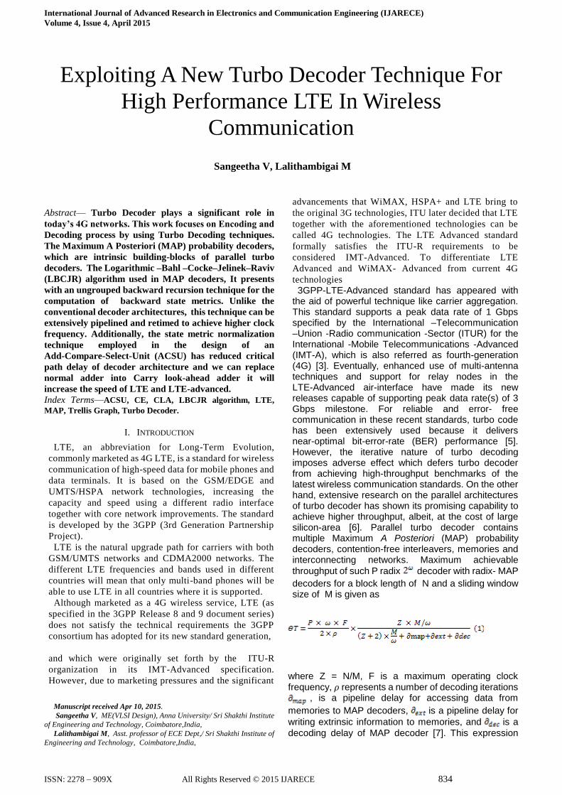
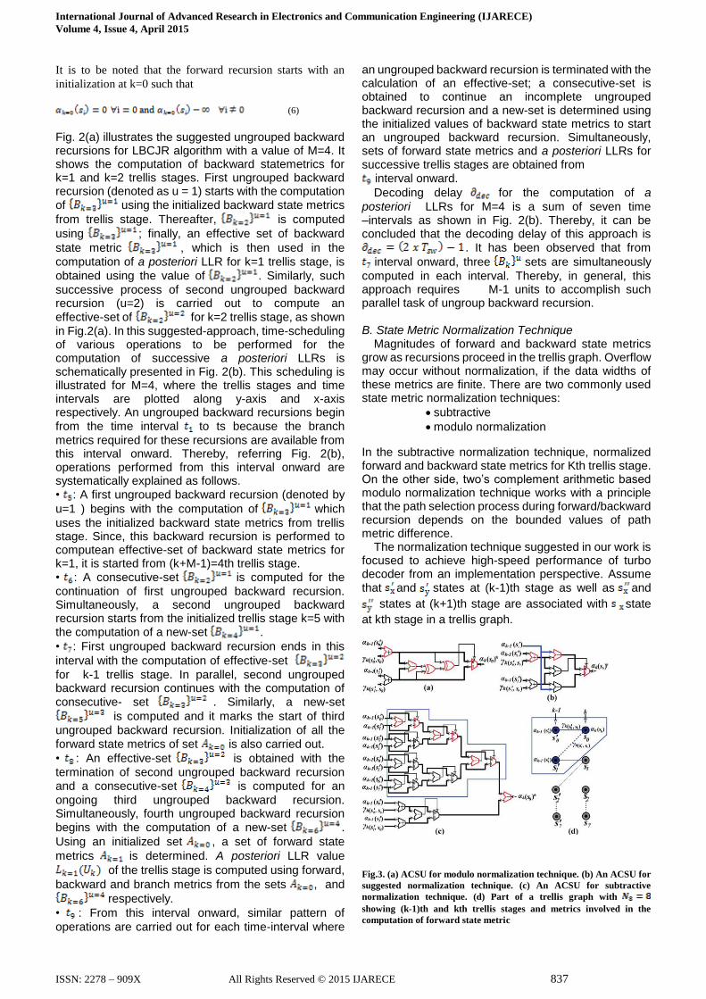
In the subtractive normalization technique, normalized forward and backward state metrics for Kth trellis stage. On the other side, two’s complement arithmetic based modulo normalization technique works with a principle that the path selection process during forward/backward recursion depends on the bounded values of path metric difference. The normalization technique suggested in our work is focused to achieve high-speed performance of turbo decoder from an implementation perspective. Assume that and states at (k-1)th stage as well as and
states at (k+1)th stage are associated with state
at kth stage in a trellis graph.
Fig.3. (a) ACSU for modulo normalization technique. (b) An ACSU for
suggested normalization technique. (c) An ACSU for subtractive
normalization technique. (d) Part of a trellis graph with
showing (k-1)th and kth trellis stages and metrics involved in the
computation of forward state metric
International Journal of Advanced Research in Electronics and Communication Engineering (IJARECE)
Volume 4, Issue 4, April 2015
ISSN: 2278 – 909X All Rights Reserved © 2015 IJARECE 838
IV. DECODER ARCHITECTURE AND SCHEDULING
We next present the MAP-decoder architecture and its scheduling based on the proposed techniques. Detail discussion on the design of high-speed MAP decoder, and its implementation trade-offs, are carried out. Furthermore, parallel architecture of turbo decoder and QPP interleaver used in this work are presented.
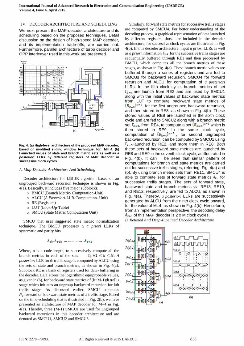
Fig. 4. (a) High-level architecture of the proposed MAP decoder,
based on modified sliding window technique, for M= 4. (b)
Launched values of state and branch metric sets as well as a
posteriori LLRs by different registers of MAP decoder in
successive clock cycles.
A. Map-Decoder Architecture And Scheduling
Decoder architecture for LBCJR algorithm based on an
ungrouped backward recursion technique is shown in Fig.
4(a). Basically, it includes five major subblocks:
o BMCU (Branch Metric- Computation-Unit)
o ALCU (A Posteriori-LLR-Computation- Unit)
o RE (Registers)
o LUT (Look-Up-Table)
o SMCU (State Matric Computation Unit)
SMCU that uses suggested state metric normalization
technique. The BMCU processes n a priori LLRs of
systematic and parity bits
Where, n is a code-length, to successively compute all the
branch metrics in each of the sets A
posteriori LLR for th trellis stage is computed by ALCU using
the sets of state and branch metrics, as shown in Fig. 4(a).
Subblock RE is a bank of registers used for data- buffering in
the decoder. LUT stores the logarithmic equiprobable values,
as given in (6), for backward state metrics of (k+M-1)th trellis
stage which initiates an ungroup backward recursion for kth
trellis stage. As discussed earlier, SMCU computes
forward or backward state metrics of a trellis stage. Based
on the time-scheduling that is illustrated in Fig. 2(b), we have
presented an architecture of MAP decoder for M=4 in Fig.
4(a). Thereby, three (M-1) SMCUs are used for ungrouped
backward recursions in this decoder architecture and are
denoted as SMCU1, SMCU2 and SMCU3.
Similarly, forward state metrics for successive trellis stages
are computed by SMCU4. For better understanding of the
decoding process, a graphical representation of data launched
by different registers, those are included in the decoder
architecture, for successive clock cycles are illustrated in Fig.
4(b). In this decoder architecture, input a priori LLRs as well
as a priori information for the successive trellis stages are
sequentially buffered through RE1 and then processed by
BMCU, which computes all the branch metrics of these
stages, as shown in Fig. 4(a). These branch metric values are
buffered through a series of registers and are fed to SMCUs for backward recursion, SMCU4 for forward recursion and ALCU for computation of a posteriori
LLRs. In the fifth clock cycle, branch metrics of set are launch from RE2 and are used by SMCU1
along with the initial values of backward state metrics from LUT to compute backward state metrics of
, for the first ungrouped backward recursion,
and then stored in RE8, as shown in Fig. 4(b). These stored values of RE8 are launched in the sixth clock cycle and are fed to SMCU2 along with a branch metric set , from RE4, to compute a set which is
then stored in RE9. In the same clock cycle, computation of , for second ungrouped
backward recursion, can be computed by SMCU1 using launched by RE2, and store them in RE8. Both
these sets of backward state metrics are launched by RE8 and RE9 in the seventh clock cycle, as illustrated in Fig. 4(b). It can be seen that similar pattern of computations for branch and state metrics are carried out for successive trellis stages, referring Fig. 4(a) and (b). By using branch metric sets from RE11, SMCU4 is able to compute sets of forward state metrics , for
successive trellis stages. The sets of forward state, backward state and branch metrics via RE13, RE10, and RE12, respectively, are fed to ALCU, as shown in Fig. 4(a). Thereby, a posteriori LLRs are successively generated by ALCU from the ninth clock cycle onward, for the value of M=4, as shown in Fig. 4(b). Henceforth, from an implementation perspective, the decoding delay
of this MAP decoder is 2 x M clock cycles.
B. Retimed And Deep-Pipelined Decoder Architecture
International Journal of Advanced Research in Electronics and Communication Engineering (IJARECE)
Volume 4, Issue 4, April 2015
ISSN: 2278 – 909X All Rights Reserved © 2015 IJARECE 839
Fig.5. (a) Data-flow-graph of retimed SMCU for computing Ns = 4
forward state metrics. (b) Timing diagram for the operation of retimed
SMCU with clk1 and clk2.
In the suggested MAP-decoder architecture, SMCU4 with
buffered feedback paths is used in forward recursion and it
imposes a critical path delay of from (11). On the other hand,
SMCU4 architecture can be retimed to shorten this critical
path delay. For a trellis-graph of , retimed dataflow- graph of
SMCU with buffered feedback paths for computing the
forward state metrics of successive trellis stages is shown in
Fig. 5(a). It has four ACSUs based on suggested state metric
normalization technique and they compute forward state
metrics using normalizing factor. However, this retimed
data-flow-graph based architecture operates with a clock that
has double the frequency of clock at which the branch metrics
are fed, as shown in Fig. 5(b). Otherwise, it may miss the
successive forward state metrics from th stage to compute
state metrics for th trellis stage. It can be seen that the critical
path of this SMCU has only a subtractor delay, thereby; this
retimed-unit can be operated at higher clock frequency.
An advantage of the suggested MAP decoder architecture
is that the SMCUs for backward recursion process can also be
pipelined.
This increases a data-processing frequency at which the
branch metrics are fed to retimed SMCU that is already
operating at higher clock frequency. However, such retimed
SMCU is not suitable for conventional MAP decoder because
the SMCUs for backward recursion in such decoder-design
have feedback architectures. Thereby, they cannot be
pipelined to enhance the data-processing frequency, though
the retimed SMCU are operating at higher clock frequency
[11].
1) High-Speed Map Decoder Architecture
In this work, we have presented architecture of MAP decoder for turbo decoding, as per the specifications of 3GPP-LTE/LTE-Advanced [3]. It has been designed for an eight-state convolutional encoder with a transfer function of .
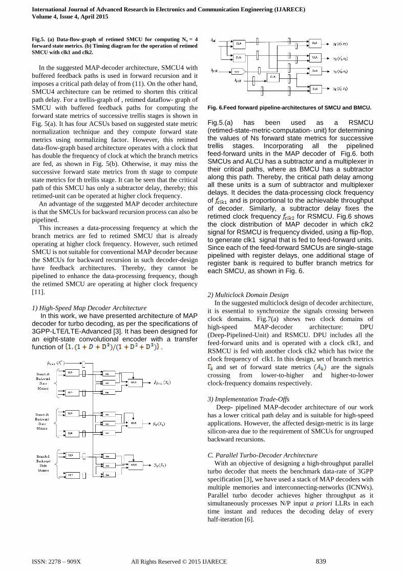
Fig. 6.Feed forward pipeline-architectures of SMCU and BMCU.
Fig.5.(a) has been used as a RSMCU (retimed-state-metric-computation- unit) for determining the values of Ns forward state metrics for successive trellis stages. Incorporating all the pipelined feed-forward units in the MAP decoder of Fig.6. both SMCUs and ALCU has a subtractor and a multiplexer in their critical paths, where as BMCU has a subtractor along this path. Thereby, the critical path delay among all these units is a sum of subtractor and multiplexer delays. It decides the data-processing clock frequency of and is proportional to the achievable throughput
of decoder. Similarly, a subtractor delay fixes the retimed clock frequency for RSMCU. Fig.6 shows
the clock distribution of MAP decoder in which clk2 signal for RSMCU is frequency divided, using a flip-flop, to generate clk1 signal that is fed to feed-forward units. Since each of the feed-forward SMCUs are single-stage pipelined with register delays, one additional stage of register bank is required to buffer branch metrics for each SMCU, as shown in Fig. 6.
2) Multiclock Domain Design
In the suggested multiclock design of decoder architecture,
it is essential to synchronize the signals crossing between
clock domains. Fig.7(a) shows two clock domains of
high-speed MAP-decoder architecture: DPU
(Deep-Pipelined-Unit) and RSMCU. DPU includes all the
feed-forward units and is operated with a clock clk1, and
RSMCU is fed with another clock clk2 which has twice the
clock frequency of clk1. In this design, set of branch metrics
and set of forward state metrics are the signals
crossing from lower-to-higher and higher-to-lower
clock-frequency domains respectively.
3) Implementation Trade-Offs
Deep- pipelined MAP-decoder architecture of our work
has a lower critical path delay and is suitable for high-speed
applications. However, the affected design-metric is its large
silicon-area due to the requirement of SMCUs for ungrouped
backward recursions.
C. Parallel Turbo-Decoder Architecture
With an objective of designing a high-throughput parallel
turbo decoder that meets the benchmark data-rate of 3GPP
specification [3], we have used a stack of MAP decoders with
multiple memories and interconnecting-networks (ICNWs).
Parallel turbo decoder achieves higher throughput as it
simultaneously processes N/P input a priori LLRs in each
time instant and reduces the decoding delay of every
half-iteration [6].
International Journal of Advanced Research in Electronics and Communication Engineering (IJARECE)
Volume 4, Issue 4, April 2015
ISSN: 2278 – 909X All Rights Reserved © 2015 IJARECE 840
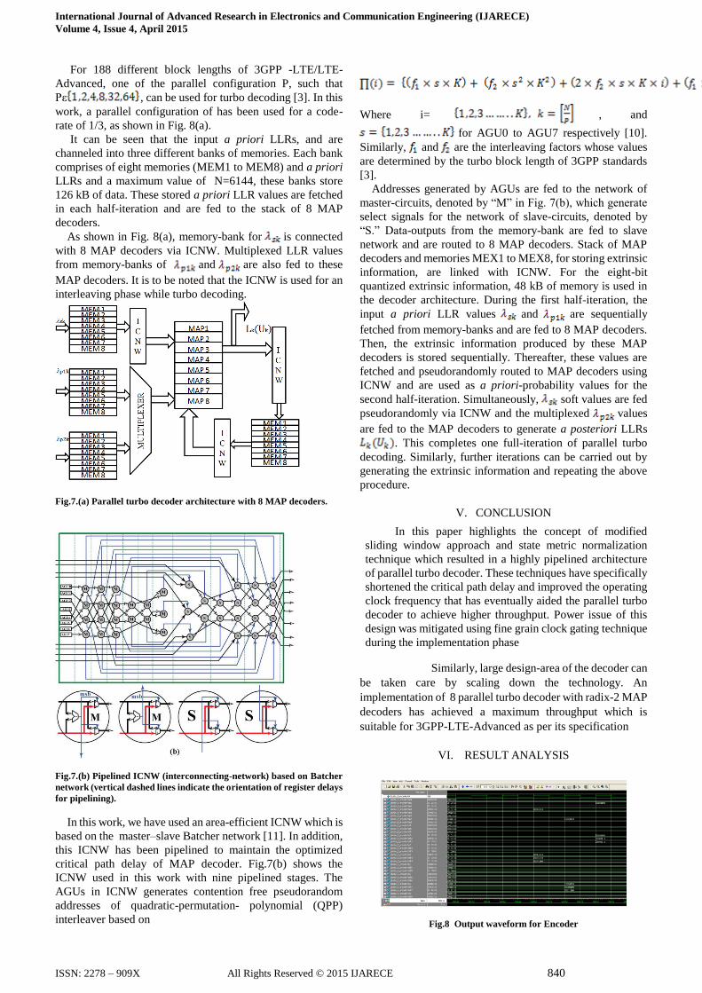
For 188 different block lengths of 3GPP -LTE/LTE-
Advanced, one of the parallel configuration P, such that
Pε , can be used for turbo decoding [3]. In this
work, a parallel configuration of has been used for a code-
rate of 1/3, as shown in Fig. 8(a).
It can be seen that the input a priori LLRs, and are
channeled into three different banks of memories. Each bank
comprises of eight memories (MEM1 to MEM8) and a priori
LLRs and a maximum value of N=6144, these banks store
126 kB of data. These stored a priori LLR values are fetched
in each half-iteration and are fed to the stack of 8 MAP
decoders.
As shown in Fig. 8(a), memory-bank for is connected
with 8 MAP decoders via ICNW. Multiplexed LLR values
from memory-banks of and are also fed to these
MAP decoders. It is to be noted that the ICNW is used for an
interleaving phase while turbo decoding.
Fig.7.(a) Parallel turbo decoder architecture with 8 MAP decoders.
Fig.7.(b) Pipelined ICNW (interconnecting-network) based on Batcher
network (vertical dashed lines indicate the orientation of register delays
for pipelining).
In this work, we have used an area-efficient ICNW which is
based on the master–slave Batcher network [11]. In addition,
this ICNW has been pipelined to maintain the optimized
critical path delay of MAP decoder. Fig.7(b) shows the
ICNW used in this work with nine pipelined stages. The
AGUs in ICNW generates contention free pseudorandom
addresses of quadratic-permutation- polynomial (QPP)
interleaver based on
Where i= , and
for AGU0 to AGU7 respectively [10].
Similarly, and are the interleaving factors whose values
are determined by the turbo block length of 3GPP standards
[3].
Addresses generated by AGUs are fed to the network of
master-circuits, denoted by ―M‖ in Fig. 7(b), which generate
select signals for the network of slave-circuits, denoted by
―S.‖ Data-outputs from the memory-bank are fed to slave
network and are routed to 8 MAP decoders. Stack of MAP
decoders and memories MEX1 to MEX8, for storing extrinsic
information, are linked with ICNW. For the eight-bit
quantized extrinsic information, 48 kB of memory is used in
the decoder architecture. During the first half-iteration, the
input a priori LLR values and are sequentially
fetched from memory-banks and are fed to 8 MAP decoders.
Then, the extrinsic information produced by these MAP
decoders is stored sequentially. Thereafter, these values are
fetched and pseudorandomly routed to MAP decoders using
ICNW and are used as a priori-probability values for the
second half-iteration. Simultaneously, soft values are fed
pseudorandomly via ICNW and the multiplexed values
are fed to the MAP decoders to generate a posteriori LLRs
. This completes one full-iteration of parallel turbo
decoding. Similarly, further iterations can be carried out by
generating the extrinsic information and repeating the above
procedure.
V. CONCLUSION
In this paper highlights the concept of modified
sliding window approach and state metric normalization
technique which resulted in a highly pipelined architecture
of parallel turbo decoder. These techniques have specifically
shortened the critical path delay and improved the operating
clock frequency that has eventually aided the parallel turbo
decoder to achieve higher throughput. Power issue of this
design was mitigated using fine grain clock gating technique
during the implementation phase
Similarly, large design-area of the decoder can
be taken care by scaling down the technology. An
implementation of 8 parallel turbo decoder with radix-2 MAP
decoders has achieved a maximum throughput which is
suitable for 3GPP-LTE-Advanced as per its specification
VI. RESULT ANALYSIS
Fig.8 Output waveform for Encoder
International Journal of Advanced Research in Electronics and Communication Engineering (IJARECE)
Volume 4, Issue 4, April 2015
ISSN: 2278 – 909X All Rights Reserved © 2015 IJARECE 841
The fig.8 shows the output waveform for Encoder. The
input will be splited up as Systematic bit and Parity bits
(P1, P2) by using Convolutional Coder, to produce the
encoder output.
Fig.9 Output waveform for Decoder
The fig.9. shows the output waveform for Decoder. Based
upon the techniques like Modulo normalization, Subtractive
normalization and Trellis graph the 8 bit input will be proceed
in BMCU and SMCU blocks to provide the decoded output.
REFERENCES
[1] Belfanti .S, Roth .C, Gautschi .M, Benkeser .C, and Huang .Q, ―A 1 Gbps
LTE-advanced turbo-decoder ASIC in 65 nm CMOS,‖ in Proc. Symp. VLSI
Circuits (VLSIC), 2013.
[2] Condo .C, Martina .M, and Masera.G, ―VLSI implementation of a
multi-mode turbo/LDPC decoder architecture,‖ IEEE Trans. Circuits, Jun.
2013.
[3] Dobkin.R, M. Peleg, and R. Ginosar, ―Parallel VLSI architecture for
MAP turbo decoder,‖ in Proc. IEEE Int. Symp. Personal, Indoor Mobile
Radio Commun., 2002.
[4] Lin .C, Chen .C, and Wu .A, ―Area-efficient scalable MAP processor
design for high -throughput multi -standard convolutional turbo
decoding,‖ IEEE Trans. Very Large Scale Integr. (VLSI) Syst., Feb. 2011.
[5] Studer .C, Benkeser .C, Belfanti.S, and Q. Huang, ―Design and
implementation of a parallel turbo-decoder ASIC for 3GPP-LTE,‖ IEEE J.
Solid-State Circuits, Jan. 2011.
[6] T. Ilnseher, F. Kienle, C. Weis, and N. Wehn, ―A 2.15 GBit/s turbo code
decoder for LTE advanced base station applications,‖ in Proc. Int. Symp.
Turbo Codes and Iterative Information Processing (ISTC),2012.
[7] Wong C.C, M.-W. Lai, C.-C. Lin, H.-C. Chang, and C.-Y. Lee, ―Turbo
decoder using contention-free interleaver and parallel architecture,‖ IEEE J.
Solid-State Circuits, vol. 45, no. 2, pp. 422–432,
Feb. 2010.
[8] Wong C.-C. and H.-C. Chang, ―Reconfigurable turbo decoder with
parallel architecture for 3GPP LTE system,‖ IEEE Trans. Circuits Syst. II:
Exp. Briefs, vol. 57, no. 7, pp. 566–570, Jul. 2010.
[9] 3GPP; Technical Specification Group Radio Access Network;
E-UTRA; Multiplexing and Channel Coding (Release 10) 3GPP, TS 36.212,
Rev. 10.0.0,2012.
[10] 3GPP; “User Equipment (UE) Radio Access Capabilities,” TS
36.306 V11.2.0, Dec.2012.
[11] 3GPP; Technical Specification Group Radio Access Network;
E-UTRA; Multiplexing an Channel Coding (Release 9) 3GPP, TS 36.212,
Rev. 8.3.0, May 2008.
[12] http://www.3gpp.org/
[13] http://www.gsacom.com/3gpp/index.php4
Sangeetha V did her Bachelor of Engineering in Electronics and
Communication Engineering at Sri subramanya College of
Engineering and Technology, Palani and doing Masters of
Engineering in VLSI Design at Sri Shakthi Institute of Engineering
and Technology, Coimbatore,India. .Her research interests are
Wireless Networks and VLSI Design.
Lalithambigai M, Assistant Professor working in the Department
of Electronics and Communication Engineering at Sri Shakthi
Institute of Engineering and Technology, Coimbatore, India. She
received her Master of Engineering (ME) degree in 2014 from Sona
College of Technology, Salem, India. Her research interests are in
VLSI Design and Communication.