Embed Size (px)
Citation preview

Tribology International ] (]]]]) ]]]–]]]
Contents lists available at SciVerse ScienceDirect
Tribology International
0301-67
doi:10.1
n Corr
E-m
franci.m
Pleasoper
journal homepage: www.elsevier.com/locate/triboint
Experimental validation of the lifetime performance of a proportional 4/3hydraulic valve operating in water
F. Majdic n, J. Pezdirnik, M. Kalin
Askerceva 6, SI-1000 Ljubljana, Slovenia, EU
a r t i c l e i n f o
Article history:
Received 6 May 2011
Received in revised form
27 August 2011
Accepted 30 August 2011
Keywords:
Distilled water
Proportional directional hydraulics valve
Stainless steel
Durability
9X/$ - see front matter & 2011 Elsevier Ltd. A
016/j.triboint.2011.08.020
esponding author. Tel.: þ386 1 4771 413; fax
ail addresses: [email protected],
[email protected] (F. Majdic).
e cite this article as: Majdic F, et alating in water. Tribol Int (2011), doi
a b s t r a c t
One of the alternative hydraulic fluid is water, which is environmentally acceptable, low-cost and non-
flammable. We have designed a new hydraulic test rig and a new water proportional control valve to
investigate the tribological and hydraulic behaviour of such water-based systems under pressures of up
to 16 MPa and flows of up to 30 lpm. In this work, we present the lifetime performance of all-stainless-
steel valve with distilled water being used as the hydraulic fluid. The results show that the water-based
valve can operate for more than 10 million cycles under industrial relevant conditions if the water
cleanness is appropriately maintained.
& 2011 Elsevier Ltd. All rights reserved.
1. Introduction
With technological progress and global industrialisation, ecol-ogy is becoming more and more important for sustainabledevelopment world-wide. Power-control hydraulics is an impor-tant area of mechanical engineering [1–3], where large quantitiesof harmful substances (i.e., hydraulic fluids) threaten the envir-onment with potential pollution resulting from accidents andoccasional spillages [4]. It is well known that some outflows interms of noxious hydraulic fluids occur during everyday opera-tions, even with regular maintenance [5]. There are two possiblesolutions to improve this situation: the first one is to usebiodegradable oils [6–10]; the second one is to use tap water asthe hydraulic fluid [11,12]. The second one is much more effectiveand environmentally neutral, but it is more difficult to achieve.The employment of tap water in hydraulic systems implies acompletely different environment for all the mechanical andhydraulic components, different dynamic and lubricating condi-tions, and this requires a completely or partially modified selec-tion of materials and the design of the hydraulic system [13].
In today’s industrial-scale-components market we find mainlysimple, water-based components and systems, while more complexcomponents that would enable the use of a larger amount andvariety of water-based hydraulic systems instead of oil basedsystems are still to a large extent missing. Accordingly, there is a
ll rights reserved.
: þ386 1 4771 469.
. Experimental validation o:10.1016/j.triboint.2011.08.
clear need to develop new and more advanced water-hydrauliccomponents. In particular, continuous-control hydraulic systems areof great interest since they are required in almost every advancedhydraulic system, but to our knowledge, the development of thesewater-based components has not yet taken place [14].
These reasons motivated us to develop a new proportional 4/3directional control valve suitable for water-hydraulic applica-tions. Several specific requirements are associated with this kindof valve when the spool and the sleeve are sliding in water.Namely, the low viscosity of water suggests that the gap betweenthe spool and the sleeve should be very low in order to maintain alow internal leakage and a high volumetric efficiency. On theother hand, this further implies the need for very accuratemanufacturing with close design tolerances (circumference andcylinder) and a low roughness. Moreover, a small gap combinedwith a relatively poor lubricant (i.e., water) also suggests thedanger of there being high friction and wear for the contactingsurfaces. For this reason, filtering will probably also play animportant role in any successful operation. With these constraintsidentified, the materials should be properly selected, on the basisof tribological and corrosion performance, as well as taking intoaccount machinability and costs.
It is clear that steel is not the best material for water-lubricated applications for reasons of corrosion, wear and friction.Certain types of ceramics, which are known to provide relativelylow wear and friction under water lubrication [18–22] and whichare actually widely used in several water-based applications,might be more appropriate. Another potential class of materialsare polymers, due to their low adhesion, low specific weight andtheir excellent corrosion resistance. However, polymers are
f the lifetime performance of a proportional 4/3 hydraulic valve020

Nomenclature
QL,max maximal internal leakage flow of the valve [m3/s]Qnp measured internal leakage flow [m3/s]nip number of the leaving cross-sectionsDp pressure difference in the gap [Pa]Dm middle diameter [m]
S gap between spool and sleeve, when spool is in thecentric position [m]
fecc factor of eccentricityr density [kg/m2]u kinematic viscosity [m2/s]L axial overlap between spool and the sleeve in the
neutral position of the spool [m]
F. Majdic et al. / Tribology International ] (]]]]) ]]]–]]]2
sometimes very difficult to manufacture to appropriate tolerancesand experience dimensional instability, while ceramics are veryexpensive and suffer from fracture. Therefore, none of thesematerials can be easily introduced and would require detailedoptimisation for any specific application. In our preliminarytribological pin-on-disc study with various pairs using alumina,PEEK, polyimide and stainless steel [15] we observed that cera-mics may be one of the best materials for such an application.However, stainless steel, which is the easiest to apply andmanufacture and is quite inexpensive, also showed reasonablygood wear performance, although the friction was the highestamong the tested materials. Thus, it is of interest to observe howthe stainless steel would perform under real water-hydraulicconditions. Accordingly, in this work we have performed anexperimental long-term validation test of a stainless-steel pro-portional 4/3 valve operating under water-lubrication conditionsusing our own-designed test rig and valve [16,17].
2. Water-hydraulic test rig
2.1. Requirements for the test rig
A new proportional water 4/3 directional control valve wasdesigned to study the water-based hydraulic system. In order toreduce the testing costs, the testing valve needed to have a simpledesign, which could allow the fast and easy exchange of materialsand provide good surface control of the spool and the sleeve. Thespool and the sleeve should be small enough to fit into varioussurface-analyses devices (SEM, AFM, etc.). The selected materialpair for the spool and the sleeve should allow precise
Fig. 1. (a) Hydraulic circuit block-diagram of
Please cite this article as: Majdic F, et al. Experimental validation ooperating in water. Tribol Int (2011), doi:10.1016/j.triboint.2011.08
manufacturing in order to provide low internal leakage; the gapbetween them should be around 1 mm.
The water-hydraulic test rig should also allow measurementsof pressure, flow, temperature, internal leakage and mechanicalmovement at different functional positions. It should be able tomaintain a constant, stable working temperature (between 20and 80 1C), controllable filtering conditions and, for generalpurposes, a comparable working flow (settable from 1 to35 lpm) and pressure (settable from 50 to 16 MPa). It should alsohave its own electronic regulation.
2.2. Design characteristics
Fig. 1a shows the hydraulic circuit block-diagram of the water-hydraulic test rig. It contains a standard, commercially availableaxial piston pump with a flow of 35 lpm [17] at 1450 r/min and avolumetric efficiency of 97%. This pump delivers water to theactual specimen, which is in our case a proportional 4/3 direc-tional control water valve (Fig. 2). This valve was operated with aPC in a closed loop. On the connection port A (outlet pressure) ofthe proportional valve, we connected a stainless-steel tube towhich the pressure transmitter and the fixed orifice with adiameter of 1.5 mm at the end were connected (Fig. 3). Fixedorifices were used to simulate the load at the ports A and B of thewater proportional valve. The second branch on the connection Bwas the same as the first one. The water relief valve was set to16 MPa. A centrifugal water pump was used to maintain aconstant temperature (air cooler) and to enable off-line filtering.The pressures on the P and T connection ports of the waterproportional valve were measured during the test using twopressure transmitters. A pressure-line water filter with a rating
the water test rig, (b) photo of test rig.
f the lifetime performance of a proportional 4/3 hydraulic valve.020
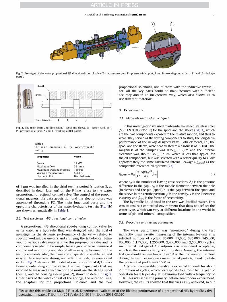
Fig. 2. Prototype of the water proportional 4/3 directional control valve (T—return-tank port, P—pressure-inlet port, A and B—working-outlet ports, L1 and L2—leakage
ports).
Fig. 3. The main parts and dimensions—spool and sleeve. (T—return-tank port,
P—pressure-inlet port, A and B—working-outlet ports).
Table 1The main properties of the water-hydraulic
test rig.
Properties Valve
Power 11 kW
Maximum flow 36 l/min
Maximum working pressure 160 bar
Working temperatures 5–60 1C
Hydraulic fluid Distilled water
F. Majdic et al. / Tribology International ] (]]]]) ]]]–]]] 3
of 1 mm was installed in the third testing period (situation 3, asdescribed in detail later on) on the P line—close to the waterproportional directional control valve. The control of the propor-tional magnets, the data acquisition and the electromotors wasautomated through a PC. The main functional parts and theoperating characteristics of the water-hydraulic test rig (Fig. 1b)are shown schematically in Table 1.
2.3. Test specimen—4/3 directional control valve
A proportional 4/3 directional spool-sliding control valve forusing water as a hydraulic fluid was designed with the goal ofinvestigating the dynamic performance of the valve related tospecific working parameters and studying the tribological beha-viour of various valve materials. For this purpose, the valve and itscomponents needed to be simple, have a good external numericalcontrol and monitoring and should allow easy replacement of thetesting elements. Also, their size and shape should enable fast andeasy surface analyses during and after the tests, as mentionedearlier. Fig. 2 shows a 3D model of our proportional 4/3 direc-tional spool-sliding control valve. The two major parts that areexposed to wear and affect friction the most are the sliding spool(pos. 1) and the housing sleeve (pos. 2), shown in detail in Fig. 2.Other parts of the valve consist of the springs, the outer housing,the adaptors for the proportional solenoid and the two
Please cite this article as: Majdic F, et al. Experimental validation ooperating in water. Tribol Int (2011), doi:10.1016/j.triboint.2011.08.
proportional solenoids, one of them with the inductive transdu-cer. All the key parts could be manufactured with sufficientaccuracy and in an inexpensive way, which also allows us touse different materials.
3. Experimental
3.1. Materials and hydraulic liquid
In this investigation we used martensitic hardened stainless steel(SIST EN X105CrMo17) for the spool and the sleeve (Fig. 3), whichare the two components exposed to the relative motion, and thus towear. They served as the testing components to study the long-termperformance of the newly designed valve. Both elements, i.e., thespool and the sleeve, were heat treated to a hardness of 55 HRC. Theroughness of the samples was 0.2570.15 mm and the internalclearance was about 1.7570.7 mm, which is less than typical forthe oil components, but was selected with a better quality to allowapproximately the same calculated internal leakage (QL,max) as thecomparable reference oil systems [23]
QL,max ¼ nipp12
DpDms3
ruLfecc
� �ð1Þ
where np is the number of leaving cross-sections, Dp is the pressuredifference in the gap, Dm is the middle diameter between the hole(in sleeve) and the pin (spool), s is the gap between the spool andthe sleeve in the centric position, r is the density, n is the kinematicviscosity and feksc is the factor of eccentricity.
The hydraulic liquid used in the test was distilled water. Thiswas to ensure a controlled environment that does not reflect thewater type, which can vary at different locations in the world interms of pH and mineral composition.
3.2. Procedure and testing parameters
The wear performance was ‘‘monitored’’ during the testindirectly using ex-situ measuring of the internal leakage at aselected number of cycles: 35,000, 95,000, 335,000, 545,000,800,000, 1,155,000, 1,255,000, 2,400,000 and 2,500,000 cycles.An internal leakage of 100 ml/min was considered acceptable,which is the same as in typical oil valves. Namely, the internalleakage should remain lower than 1% of the maximum fluid flowduring the test. Leakage was measured at ports A, B and T, whilethe pressure at port P was 16 MPa.
A typical, comparable oil-valve is expected to work for about2.5 million of cycles, which corresponds to almost half a year ofoperation for 8 h per day at maximum load with a frequency of1 Hz. This was set as the primary lifetime goal for our experiment.However, the results showed that this was easily achieved, so our
f the lifetime performance of a proportional 4/3 hydraulic valve020

F. Majdic et al. / Tribology International ] (]]]]) ]]]–]]]4
testing plan was modified and the test was continued underdifferent conditions to make maximum use of the set-up that wasalready in place.
We tried to evaluate the importance of filtering, so first wecontinued the test without any filtering. After approximately4 million cycles, a major failure occurred. The parts weredismounted and repaired (polished), but the damage was rela-tively small so the test could continue.
In the third test stage, based on our experience of the importanceof filtering, we ran the test again with filtering, but this time, evenbetter than in the first stage (0–2.5 million cycles). The test ran for10 million of cycles, and then the test was stopped in spite ofacceptable performance, as will be presented in the results section.
The three test phases are presented in Fig. 4.Another way of monitoring the performance during the test
involved visual inspections of the spool surface and SEM imagesthat were taken at different intervals. Namely, the valve was
Fig. 4. Three different regimes of the water proportional directional control
lifetime test.
Fig. 5. (a) Theoretical input signal, and (b) response-measured signals of t
Fig. 6. Example of measured pressures (a) at P and (b) at A and B connections of water 4
20 lpm, frequency¼5 Hz).
Please cite this article as: Majdic F, et al. Experimental validation ooperating in water. Tribol Int (2011), doi:10.1016/j.triboint.2011.08
analysed before the test, and was dismounted after 95,000,2,670,000 and at the end of the test at 10,000,000 cycles. Atevery inspection interval, all the parts of the valve were carefullydismounted, cleaned in ethanol, analysed and then cleaned againin ethanol and mounted on the valve to continue the test. Thesame inspection, together with the roundness and roughnessmeasurements, and the repair, was also performed during theoccurrence of the major failure at 4,010,000 cycles, when thespool was blocked in the sleeve.
3.3. Testing parameters
The maximum possible inlet pressure at the P connection (seeFigs. 2 and 3) on the specimen (water proportional 4/3 valve) was16 MPa, which enabled the maximum working pressures at the Aand B connections – depending on the flow through the orifices(Fig. 1—load) – 12 MPa. The working flow through the orificeswas 20 lpm. The frequency of the spool was 5 Hz and its controlsignal was 7100% of the spool stroke.
Schematic diagrams of the theoretical input driving signal(Fig. 5a) and the experimentally obtained values are presented inFigs. 5b and 6.
Fig. 6a shows the measured pressure on the inlet port P (seeFigs. 2 and 3). The pressure responses of the different positions ofthe spool at the working ports A and B are shown in Fig. 6b. Fromthe measured signals it is clear that the specimen (i.e., the slidingspool and the sleeve) in the water proportional 4/3 directionalcontrol valve was dynamically loaded at all three ports: P, A and B.
he spool position (pressure¼16 MPa, flow¼20 lpm, frequency¼5 Hz).
/3 directional control valve as a function of time (pressure¼16 MPa, flow¼approx.
f the lifetime performance of a proportional 4/3 hydraulic valve.020

F. Majdic et al. / Tribology International ] (]]]]) ]]]–]]] 5
4. Results
4.1. Phase 1—testing with single filtering
Fig. 7 shows the internal leakage measurements during phase1, i.e., from the start to 2.5 million cycles. Each measurement (adot) on the full line in the diagram represents the mean value ofat least three measurements of internal leakage at 401 andpressure 16 MPa. These results correspond to an increase in theinternal leakage from an initial 0.036 l/min up to 0.0843 l/min,after 2.5 million cycles. The increase is continuous and gradual;however, it should be noted that the leakage value representsonly 0.2% of the maximum outflow of the water pump, which is avery small internal leakage and far below acceptable operatinglimits, even for comparable oil-hydraulic systems. There wassome variation noticed in the measurements, which may be dueto different positions of the spool during the time of the internalleakage measurements. Namely, it is known that the exactposition of the spool inside the bore of the sleeve could affectsome variations in the internal leakage [23]. Another source of thevariation is the measurement uncertainty.
Fig. 7. Internal leakage of water directional 4/3 proportional control valve from start up
Twater¼40 1C.)
Fig. 8. Schematic of analysed positions
Fig. 9. Representative sliding surfaces of the spool prior to the test at location (a) A a
Please cite this article as: Majdic F, et al. Experimental validation ooperating in water. Tribol Int (2011), doi:10.1016/j.triboint.2011.08.
Fig. 8 shows schematically the two positions where thesurfaces were analysed; they were selected on the assumptionthat these are the most relevant wear-sensitive locations on thespool (indicated by arrows A and B). These locations were verifiedat several positions circumferentially. Optical and SEM analyseswere performed.
Fig. 9a and b shows the surfaces at locations A and B (asindicated in Fig. 8) before the test. Several scratches are visible inthe vertical direction, which resulted from the manufacturing duringthe rotational grinding and polishing. Other scratches, as well assome edge damage, are micro-scale defects that occur during thehandling of the spool. It should be mentioned that it is mainly thehorizontally oriented scratches that increase the internal leakage asthey lie in the direction of the spool’s movement, rather than thosethat are perpendicular to the direction of motion.
The SEM images in Fig. 10 show the sliding surface of the spoolafter 95,000 cycles. Two characteristic types of damage can beobserved. The edges (Fig. 10a) are slightly rounded due to theerosion of particles in the water flow, as well as occasionallydeformed or fractured, which is, however, a consequence of themanipulation of the spool prior to the test. The top spool surface,
to 2.5 million cycles. (pressure¼16 MPa, flow¼approx. 20 l/min, frequency¼5 Hz,
of the spool investigated by SEM.
nd (b) B—as indicated in Fig. 8. (Arrows indicate the direction of spool motion.)
f the lifetime performance of a proportional 4/3 hydraulic valve020

Fig. 10. Representative sliding surfaces of the spool during the lifetime test after about 95,000 cycles, (a) surface on place A and (b) surface on place B. (Arrows indicate the
direction of spool motion.)
Fig. 11. Internal leakage of water directional 4/3 proportional control valve in phase 2 from 2.5 to 4 million of cycles. (pressure¼16 MPa, flow¼20 l/min, frequency¼5 Hz,
Twater¼40 1C.)
Fig. 12. Representative sliding surfaces of the spool during the lifetime test after 2.67 million cycles, (a) surface on place A and (b) surface on place B. (Arrows indicate the
direction of spool motion.)
F. Majdic et al. / Tribology International ] (]]]]) ]]]–]]]6
i.e., at location B, (Fig. 10b) is obviously smoothed due to two- andthree-body abrasion, but no severe damage can be observed. Inaddition, at some positions, some deeper scratches can be seen.Presumably, these are the remaining deeper scratches from themanipulation of the spool prior to the tests.
4.2. Phase 2—testing without filtering
The testing regime after 2.5 million cycles (Fig. 4) was changedwith respect to the filtering. Namely, no filtration of the waterwas performed in the period from 2.5 to 4 million cycles. In thisperiod three notable types of damage occurred on the slidingsurfaces of the spool and the bore of the sleeve. The same problemoccurred three times: some wear debris was locked between the
Please cite this article as: Majdic F, et al. Experimental validation ooperating in water. Tribol Int (2011), doi:10.1016/j.triboint.2011.08
spool and the sleeve, obviously due to the lack of filtering. Thespool stopped moving, and dismounting was necessary to relievethe spool. Due to this, some surface damage in the form of ascratch occurred. After each blockage, however, the testing spooland the sleeve were carefully polished. Polishing resulted in anincreased clearance between the spool and the sleeve, which ledto increased leakage, as seen in Fig. 11.
Fig. 12a and b shows several clearly visible horizontalscratches after 2.67 million cycles using SEM. The SEM imageswere recorded after the first damage with spool blocking occur-ring in the water valve (see Fig. 11). The horizontal scratches areprobably the result of the abrasive action from numerous hardparticles in the water, which are present due to lack of filtering.Both surfaces, i.e., the spool and the sleeve, showed the same type
f the lifetime performance of a proportional 4/3 hydraulic valve.020

F. Majdic et al. / Tribology International ] (]]]]) ]]]–]]] 7
of damage, i.e., many scratches. However, with subsequentpolishing (spool repair as a result of the wear-debris blocking),these scratches were removed, and the internal leakage increased,as mentioned before, and is shown in Fig. 11.
Fig. 15. Cavitation wear after 10 million cycles found on the sliding surface of the
spool. (Arrow indicates the direction of spool motion.)
4.3. Phase 3—testing with double filtering
After 4 million cycles (until the end of the test at 10 millioncycles), improved double filtering was included in the water-hydraulic system. Both by-pass and additional pressure filterswere applied with a filtration rate of 1 mm. During this testingperiod no blocking or any other catastrophic damage occurredand the motion of the spool followed the input signals veryconsistently Fig. 13.
The internal leakage that was measured during the periodfrom 4 to 10 million cycles varied quite significantly, mostprobably due to the increased clearance between the spool andthe sleeve after the repairs at earlier stages. The motion of thespool was thus less centric and the positions of the spool at thetime of the internal leakage measurement also affected theseresults. The measured internal leakage at the end of the testingprocedure was 1.55 lpm, which is approximately 4% of the wholeflow of the pump. Although the increase in the internal leakagedue to the repair was very significant after 4 million cycles, theinternal leakage at the end was still within the operational limits[24]. Moreover, there was no obvious increase observed from 4 to10 million cycles.
Fig. 14a and b shows the surfaces at the end of the lifetimetest, i.e., after 10 million cycles. The surfaces show no severe signsof damage, and are surprisingly like those prior to the test, Fig. 9a
Fig. 13. Internal leakage of water directional 4/3 proportional control valve from
Twater¼40 1C).
Fig. 14. Representative sliding surfaces of the spool during the lifetime test after 10 mi
direction of spool motion.)
Please cite this article as: Majdic F, et al. Experimental validation ooperating in water. Tribol Int (2011), doi:10.1016/j.triboint.2011.08.
and b. There are some scratches observed, primarily in thecircumferential direction, which originate from manufacturingand repair, rather than the wear during operation. No majorscratches or signs of damage due to sliding (direction of motion)could be observed (Fig. 14b). However, we can see some small,shallow pits (Fig. 14a), which are most probably due to cavitation,which is expected at this location [25,26]. A detail from one of themost damaged locations on the spool indicates that these pitsdeveloped a size of about 1–5 mm during the 10 million cycles(Fig. 15). Nevertheless, under the present conditions, these pitsdid not have a significant influence on the internal leakage orotherwise reduce the performance of the system, which can beclaimed on the basis of the internal leakage measurements. In thistesting period (from 4 to 10 million cycles) the sliding surfaces
4 to 10 million cycles. (pressure¼16 MPa, flow¼20 l/min, frequency¼5 Hz,
llion cycles, (a) surface on place A and (b) surface on place B. (Arrows indicate the
f the lifetime performance of a proportional 4/3 hydraulic valve020

Fig. 16. Metallic particles found in the water-hydraulic reservoir in phase 2, without filtering.
F. Majdic et al. / Tribology International ] (]]]]) ]]]–]]]8
were relatively smooth, owing to the much better and reliabledouble filtering, which significantly reduced the surface damageand improved the reliability of the water-based valve.
Other components, except the valve (spool and the sleeve), inthe water-hydraulic system were not specifically investigatedduring the test. However, we did not notice any problem duringthe operation, and almost no damage or wear phenomenon wasobserved after the system was dismounted after the 10-million-cycle test.
5. Discussion
The lifetime performance of a water proportional 4/3 direc-tional control valve was investigated for three different filteringregimes. In the first regime (phase 1—with 5 mm by-pass filter-ing), only a moderate and, according to normal practise, accep-table increase in internal leakage was noticed (Fig. 7), with mildpolishing of the surface during the running-in. The internalleakage in phase 1 was thus only 0.2% of the maximum outflowof the water pump, which is a very small amount. The samesituation can be observed in the last stage, i.e., phase 3 (with 1 mmdouble filtering), where the filtering was again obviously ade-quate (0.2% of the maximum outflow of the water pump), andeven improved, compared to phase 1. However, some fluctuationswere found, mainly due to spool repairs. The conditions in thesetwo regimes were more than satisfactory, with an almost negli-gible total increase in the internal leakage of less than 0.1% of themaximum outflow of the water pump per million cycles, which isfar below the acceptable performance, even for steel valves [24].
On the other hand, the test without the filtering in phase2 resulted in increased wear and damage in the form of scratchesand edge erosion, and even a spool-motion blockade due to wear-debris entrapment between the spool and the sleeve. Many weardebris of about 1–3 mm were noticed in this phase (see Fig. 16),which was not the case in the other two phases. Obviously,filtering plays a major role in water-based systems, probably evenmore important than in oil-hydraulic systems, because of therequired narrower clearances in these valves compared to the oil-based valves.
It is, however, surprising to find that even though the blockingof the spool occurred, the system continued to operate up to 10million cycles (Fig. 13) after the de-blockade and spool repair(surface polishing), without increasing the total internal leakageabove the expected performance level of a comparable referenceoil-based system, i.e., of around 5%. The test was ended duringthese normal operating conditions due to the far-exceededperformance over 10 million cycles of operation.
Accordingly, the lifetime test of the water-based hydraulicvalve was successfully performed up to 10 million cycles andstopped before detrimental wear or surface damage or any other
Please cite this article as: Majdic F, et al. Experimental validation ooperating in water. Tribol Int (2011), doi:10.1016/j.triboint.2011.08
system component damage. The wear mechanisms that wereobserved were abrasive scratches and cavitation pits, as well assome edge erosion due to the impacts of water-flow debris.However, the extent of these phenomena was below the accep-table limits. What is more, most of the surface damage and wearoccurred as a consequence of the incorrect filtering method(phase 2), not during the normal operation with the appropriatefiltering during phases 1 and 3.
Accordingly, the major parameter that must be kept understrict control was found to be the wear-debris filtering, whichmay otherwise cause damage to the valve and consequently amalfunction of the whole water-hydraulic system. The low inter-nal clearances in water-based systems seem to be even moresensitive to this phenomenon compared to conventional oilhydraulics due to the low clearances. On the other hand, theselection of stainless steel as a material for the tested specimens,showed acceptable wear under the proper operating conditionswith filtering. However, the expected higher friction (not mea-sured here), typical for steel in water conditions, compared tostate-of-the-art water-lubricated materials, such as ceramics[18–22], did not cause any problem or any functional reductionin the spool motion (see Figs. 6 and 7). Namely, in our compre-hensive study of water-based hydraulics [27], we have measuredsome small delay of around 3 ms in the spool motion compared tothe equivalent oil system, but at 5 Hz, as used in this work, thisdelay still satisfies all the required functional properties and doesnot affect the operating performance [27].
Accordingly, with the proper design and clearances, the correctfiltering method, the appropriate stainless-steel pre-treatment(i.e., hardened steel) and the right testing conditions, this newwater-hydraulic system and the proportional 4/3 valve werevalidated and showed an excellent industrial-parameters-vali-dated performance, which therefore confirms the great potentialfor the further development of water-based systems.
6. Conclusions
1.
f th.020
A newly designed, full stainless-steel, proportional 4/3 direc-tional control sliding type of valve was successfully run indistilled water for 10 million cycles with appropriate perfor-mance in terms of internal leakage and wear. This testing timeis even longer than the required life of such a valve in typicalindustrial applications.
2.
The surface damage to the spool and the sleeve was verymoderate in the form of minor scratches and some cavitationpits, which overall did not affect the performance of the valve.3.
The internal leakage of the tested valve at 12 MPa andthe water flow of 20 l /min was below 5% of the maximumpump flow throughout the test, indicating the industrialrelevance of the performance of the tested system. Most ofe lifetime performance of a proportional 4/3 hydraulic valve

F. Majdic et al. / Tribology International ] (]]]]) ]]]–]]] 9
Po
the system-performance reduction was during the stage withimproper filtering.
4.
With two different types of filtering (5 and 1 mm filters), thefiltering of water was found to be one of the key parametersfor the successful operation of a water-based hydraulic valve,which in the case of operation without filtering very soon ledto the malfunction of the valve. In contrast, good filteringallowed very low wear and leakage.Acknowledgements
The authors are sincerely grateful to the company Tajfun d.o.o.Planina pri Sevnici, Slovenia) for their financial and technicalsupport. For the financial support of this research we are sincerelygrateful also to the Slovenian Research Agency.
References
[1] Murrenhoff H. Grundlagen der Fluidtechnik Teil 1: Hydraulik. 5th ed.Aachen: IFAS; 2007.
[2] Findeisen D. Olhydraulik. 5th ed. Berlin Heidelberg: Springer-Verlag; 2006.[3] Murrenhoff H. Servohydraulik. 1st ed. Aachen: IFAS; 1998.[4] Krzan B, Vizintin J. Environmetally adapted lubricants. Ventil 2009;15(3):
280–6.[5] Bartz WJ. Lubricants and the environment. Tribology International
1998;31:35–47.[6] Kalin M, Vizintin J. A comparison of the tribological behaviour of steel/steel,
steel/DLC and DLC/DLC contact when lubricated with mineral and biodegrad-able oils. Wear 2006;261(1):22–31.
[7] Barriga J, Kalin M, Van Acker K, Vercammen K, Ortega A, Leiaristi L.Tribological performance of titanium doped and pure DLC coatings combinedwith a synthetic bio-lubricant. Wear 2006;261(1):9–14.
[8] Kalin M, Vizintin J, Vercammen K, Arnsek A, Barriga J, Van Acker K.Tribological performance of lubricated DLC coatings using biodegradableoils. The Coatings in Manufacturing Engineering 2004:457–65.
[9] Igartua A, Aranzabe J, Barriga J, Rodriguez B. Tribological study for theapplication of biodegradable lubricants in the Industry. In: Ronkainen H,Holmberg K, editors. COST 516 tribology symposium proceedings, VTT,Espoo; 1998. p. 135–146.
[10] Kalin M, Majdic F, Vizintin J, Pezdirnik J, Velkavrh I. Analyses of the long-termperformance and tribological bechaviour of an axial piston pump using
lease cite this article as: Majdic F, et al. Experimental validation operating in water. Tribol Int (2011), doi:10.1016/j.triboint.2011.08.
dimond-like-carbon-coated piston shoes and biodegradable oil. Journal ofTribology 2008;130:11013-1–8.
[11] Backe W. Water- or oil-hydraulics in the future. In: Proceedings of the sixthscandinavian international conference on fluid power, SICFP 1999, Tampere,Finland. p. 51–65.
[12] Kitagawa A. Co-operation between universities and water hydraulic compa-nies in Japan. In: Proceedings of the sixth scandinavian internationalconference on fluid power, SICFP 1999, Tampere, Finland.
[13] Trostmann E. Water hydraulics control technology. Lyngby: Technical Universityof Denmark; 1996.
[14] Koskinen K, Leino T, Riipinen H. Sustainable development with waterhydraulics—possibilities and challenges. In: Proceedings of the 7th JFPSinternational symposium in fluid power, Toyama, Japan, vol. 1; 2008. p. 11–18.
[15] Majdic F, Pezdirnik J, Kalin M. Comparative tribological investigations ofcontinuous control valves for water hydraulics. In: Proceedings of the 10thinternational conference on fluid power, SICFP’07, Tampere, Finland; 2007.
[16] Majdic F, Pezdirnik J. Advances in water power-control hydraulics experi-mental research. Journal of Mechanical Engineering 2008;54(12):841–9.
[17] Majdic F, Pezdirnik J. Oil- and water-based continuous control valve.Industrial Lubrication and Tribology 2010;62(3):136–43.
[18] Chen M, Kato K, Adachi K. The comparisons of sliding speed and normal loadeffect on friction coefficients of self-mated Si3N4 and SiC under waterlubrication. Tribology International 2002;35:129–35.
[19] Kalin M, Novak S, Vizintin J. Wear and friction behaviour of alumina ceramicsin aqueous solutions with different pH. Wear 2003;254:1141–6.
[20] Kalin M, Novak S, Vizintin J. Surface charge as a new concept for boundarylubrication of ceramics with water. Journal of Physics D: Applied Physics2006;39:3138–49.
[21] Andersson P. Water-lubricated pin-on-disk tests with ceramics. Wear1992;154:37–47.
[22] Kalin M, Jahanmir S, Drazic G. Wear mechanisms of glass-infiltrated aluminasliding against alumina in water. Journal of the American Ceramic Society2005;88:346–52.
[23] Pezdirnik J. Tok tekocine skozi reze v hidravlicnih sestavinah : (tok kapljevineskozi reze med soleznimi vzporednimi ploskvami brez medsebojne relativnehitrosti)¼Fluid flow through gaps in hydraulic components:(liquid flowthrough gaps between paralell surfaces without relative velocity). StrojniskiVestnik 2001;47(5):210–6.
[24] Casey B. Insider secrets to hydraulics. Australia: West Pert; 2002.[25] Zhou H, Yang H. Diagnostic of cavitation inception in water hydraulic piston
pump. In: Proceedings of the sixth scandinavian international conference onfluid power, SICFP 1999, Tampere, Finland.
[26] Suzuki K, Urata E. Improvement of cavitation resistive property of a waterhydraulic relief valve. In: Proceedings of the eight scandinavian internationalconference on fluid power, SICFP 2003, Tampere, Finland.
[27] Majdic F. Water as a liquid in power-control hydraulic; Voda kot kapljevinavpogonsko-krmilni hidravliki. Doctoral Dissertation (in Slovene). Ljubljana;2010.
f the lifetime performance of a proportional 4/3 hydraulic valve020