Embed Size (px)
Citation preview

HAL Id: hal-01371858https://hal.archives-ouvertes.fr/hal-01371858
Submitted on 26 Sep 2016
HAL is a multi-disciplinary open accessarchive for the deposit and dissemination of sci-entific research documents, whether they are pub-lished or not. The documents may come fromteaching and research institutions in France orabroad, or from public or private research centers.
L’archive ouverte pluridisciplinaire HAL, estdestinée au dépôt et à la diffusion de documentsscientifiques de niveau recherche, publiés ou non,émanant des établissements d’enseignement et derecherche français ou étrangers, des laboratoirespublics ou privés.
Experimental test facilities for representativecharacterization of space used materials
T. Paulmier, B. Dirassen, M. Belhaj, V. Inguimbert, S. Duzellier, C. Pons, S.Rémaury, D. Payan
To cite this version:T. Paulmier, B. Dirassen, M. Belhaj, V. Inguimbert, S. Duzellier, et al.. Experimental test facilitiesfor representative characterization of space used materials. 14th Spacecraft Charging TechnologyConference (SCTC 2016), Apr 2016, NOORDWIJK, Netherlands. hal-01371858

COMMUNICATION A CONGRES
Experimental test facilities forrepresentative characterization of
space used materials
T. Paulmier, B. Dirassen, M. Belhaj, V. Inguimbert, S. Duzellier, C. Pons,
S. Rémaury (CNES), D. Payan (CNES)
SCTC 2016
NOORDWIJK, PAYS-BAS
4-8 avril 2016
TP 2016-485
Powered by TCPDF (www.tcpdf.org)


14th Spacecraft Charging Technology Conference, ESA/ESTEC, Noordwijk, NL, 04-08 APRIL 2016 1
EXPERIMENTAL TEST FACILITIES FOR REPRESENTATIVE CHA RACTERIZATION OF SPACE USED MATERIALS
T. Paulmier(1), B. Dirassen(1), M. Belhaj(1), V. Inguimbert (1), S. Duzellier(1), C. Pons(1), S. Rémaury(2), D. Payan (2)
(1) ONERA ¬ The French Aerospace Lab, Toulouse F-31055, France, Email:[email protected] (2) CNES, The French Space Agency, Toulouse, France, Email: [email protected]
ABSTRACT
Dedicated experimental facilities have been developed at ONERA and CNES (Toulouse, France) for the electrical qualification of space used materials and the extraction of the different physical parameters steering their charging behaviour under electron irradiation. These facilities allow working in a large energy range between few eV up to several MeV, a large temperature range (down to -150°C and up to 600°C depending on the facility) and at high vacuum level. This paper aims at presenting the technical characteristics of these different facilities. 1. INTRODUCTION
Spacecrafts and their component materials are submitted in planetary magnetosphere to high particle radiation flux and extreme environment that could lead to important and hazardous electrical charging levels. The need for assessing external and internal charging levels and predict any risk of electrostatic discharge led to the development of several codes for the simulation of space plasma / spacecraft interaction. Experimental characterisation is moreover necessary for space material qualification, which implies the characterization of their charging behaviour through ground experimental tests under representative electron irradiation spectrum. For numerical prediction, it is important as well to extract the different key physical parameters steering charge process, such as intrinsic and radiation induced conductivity (surface and bulk), permittivity, secondary electron emission (yield and emission spectra). Dedicated experimental facilities and protocols have therefore been developed at ONERA and CNES (Toulouse, France) for these different tasks. These facilities allow working in a large energy range between few eV up to several MeV, a large temperature range (down to -150°C and up to 600°C depending on the facility) and at high vacuum level. This paper aims at presenting the technical characteristics of our different relevant facilities. These different facilities allow qualification of space used materials (conductors, insulators, semi-conductors) and the extraction of the different physical parameters steering their charging behaviour under electron irradiation. For thorough assessment of bulk intrinsic conductivity and the analysis of ionisation and ageing recovery effects, it is also of high importance to store the
irradiated materials for a long period of time. Storage has to be performed under high vacuum level without any vacuum break-up during the sample transfer to avoid any possible recovery at atmospheric pressure. Dedicated transfer unit and storage facility have also been developed for the above purpose. 2. THE SIRENE EXPERIMENTAL FACILITY
The irradiation test facility SIRENE (Fig. 1), funded by CNES and installed at ONERA (Toulouse, France) allows charge characterization under GEO-like electron irradiation spectrum. Fig. 2 presents the electron beam spectral characteristics of the SIRENE facility with an energy spectrum (Kp>5) approaching that of the geostationary charging environment. SIRENE electron spectrum ([20keV, 250pA/cm2] + [0-400keV, 50pA/cm2]) experimental simulation is achieved with the use of two monoenergetic electron beams. In order to get a spacelike electron beam, the 400keV electron beam, passing through complex diffusion foils, is dispersed in energy from 0 to 400keV. The nominal fluxes used for the 20 keV monoenergetic beam and the distributed 400 keV one are respectively equal 250 pA/cm2 and 50 pA/cm2 but can be raised respectively up to 1 nA/cm2 and 200 pA/cm2. A pumping system allows experiments at vacuum of around 10-6 mbar. The temperature of the sample holder can be controlled in the range of -180°C to 250°C allowing to reproduce the temperature variation of materials on flight. The evolution of charging potential, during and after beam cut-off are monitored using a non-contact electrostatic probe (Kelvin probe TREK 3455ET) coupled with an electrostatic voltmeter (TREK 341B).

14th Spacecraft Charging Technology Conference, ESA/ESTEC, Noordwijk, NL, 04-08 APRIL 2016 2
Figure 1 : View of the SIRENE facility
0,1
1
10
100
1000
0 100 200 300 400 500
Energy (keV)Inte
gra
ted
cu
rren
t (p
A/c
m2 )
SIRENE standardspectrum kp>5 reference spectrum
Figure 2 : SIRENE standard spectrum and reference KP>5 spectrum
This facility allows realistic assessment of potential built up in space orbit. Its flexibility allows the simulation of extreme environments different than the geostationary one (eg, MEO, LEO or other planetary radiation environments). This facility is widely used as well for the characterisation of radiation induced conductivities of space materials in vacuum thanks to the use of a penetrating 400 keV electron beam which stimulates the potential decay during the relaxation phase without inducing any bulk charging. Using this high energy electron beam and a high incoming flux on the sample (up to 5 nA.cm-2), we are able as well to perform radiative ageing on the material. Space materials, such as polymers (Kapton, Teflon, PEEK, ETFE, PEI, ...), adhesives or coverglasses, can then be aged in SIRENE with equivalent flight durations equal to several months or years. Thanks to these different experimental specifications (bulk conductivity and RIC characterisation, temperature effect) and its spectrum flexibility, the SIRENE experimental facility is highly relevant for space material qualification and extraction of physical key parameters for charging prediction.
3. THE GEODUR IRRADIATION FACILITY
GEODUR is a radiation test facility allowing the study of satellite internal and surface charging, evaluation of RIC of thick materials and sample radiative ageing using 400 keV to 2.5 MeV monoenergetic electrons. It is equipped with a 2.5 MeV Van de Graaff electron accelerator and a double scattering system for the production of a distributed electron spectrum in the energy range [200 keV – 1 MeV]. It is instrumented with a contact-less electrostatic probe and current measurement systems for the characterisation of internal charging behaviour of space elements. The temperature of the sample holder can be controlled in the range [-180 °C, +250 °C] allowing to reproduce the temperature variations of materials on flight. A pumping system allows experiments at vacuum of around 10-6 hPa. Transfer of charged samples from GEODUR to the storage facility SPIDER (or to SIRENE, DEESSE or SEMIRAMIS facilities) can be performed under vacuum with the STRASS unit transfer (see section 6).
Figure 3 : View of the GEODUR facility
4. THE SPIDER STORAGE FACILITY
The SPIDER experimental test facility enables storing irradiated dielectric materials under vacuum (up to 10-6 hPa) for a long period of time (up to several months) to study relaxation physical processes of these materials through various in-situ, controlled and automatic measurements (surface potential with Kelvin probe, leakage and displacement currents, Non-contact Pulsed Electro-acoustic Method [PEA]). This facility can be coupled with a new existing transfer unit STRASS (System for Transfer from SIRENE to SPIDER) that enables displacing, under vacuum, dielectrics irradiated samples from one test facility to an other one without any vacuum break-up (that would lead to sample discharging or annealing of radiation effect). We can then measure conductivities as low as 10-20 Ω-1.m-1. This test facility enables as well studying evolution of
14th Spacecraft Charging Technology Conference, ESA/ESTEC, Noordwijk, NL, 04-08 APRIL 2016 3
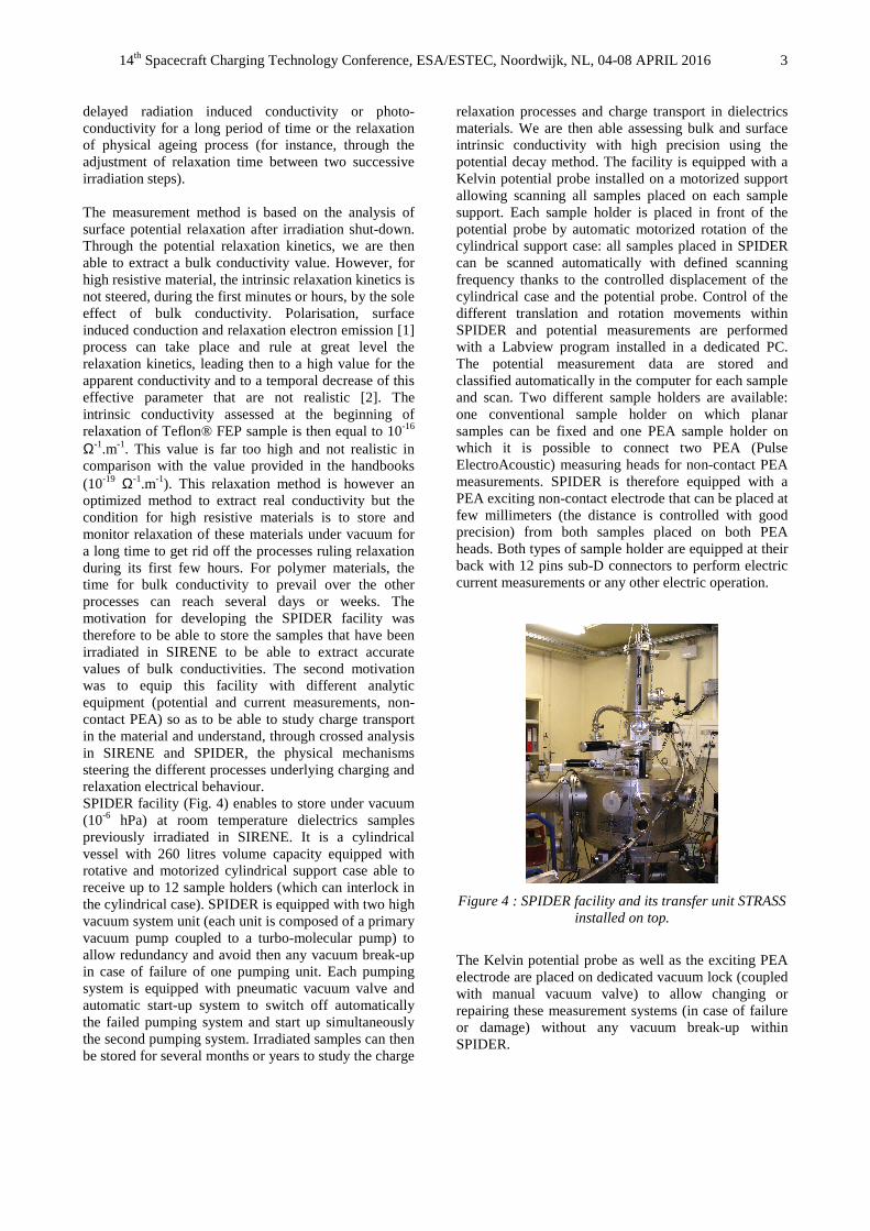
delayed radiation induced conductivity or photo-conductivity for a long period of time or the relaxation of physical ageing process (for instance, through the adjustment of relaxation time between two successive irradiation steps). The measurement method is based on the analysis of surface potential relaxation after irradiation shut-down. Through the potential relaxation kinetics, we are then able to extract a bulk conductivity value. However, for high resistive material, the intrinsic relaxation kinetics is not steered, during the first minutes or hours, by the sole effect of bulk conductivity. Polarisation, surface induced conduction and relaxation electron emission [1] process can take place and rule at great level the relaxation kinetics, leading then to a high value for the apparent conductivity and to a temporal decrease of this effective parameter that are not realistic [2]. The intrinsic conductivity assessed at the beginning of relaxation of Teflon® FEP sample is then equal to 10-16 Ω-1.m-1. This value is far too high and not realistic in comparison with the value provided in the handbooks (10-19 Ω-1.m-1). This relaxation method is however an optimized method to extract real conductivity but the condition for high resistive materials is to store and monitor relaxation of these materials under vacuum for a long time to get rid off the processes ruling relaxation during its first few hours. For polymer materials, the time for bulk conductivity to prevail over the other processes can reach several days or weeks. The motivation for developing the SPIDER facility was therefore to be able to store the samples that have been irradiated in SIRENE to be able to extract accurate values of bulk conductivities. The second motivation was to equip this facility with different analytic equipment (potential and current measurements, non-contact PEA) so as to be able to study charge transport in the material and understand, through crossed analysis in SIRENE and SPIDER, the physical mechanisms steering the different processes underlying charging and relaxation electrical behaviour. SPIDER facility (Fig. 4) enables to store under vacuum (10-6 hPa) at room temperature dielectrics samples previously irradiated in SIRENE. It is a cylindrical vessel with 260 litres volume capacity equipped with rotative and motorized cylindrical support case able to receive up to 12 sample holders (which can interlock in the cylindrical case). SPIDER is equipped with two high vacuum system unit (each unit is composed of a primary vacuum pump coupled to a turbo-molecular pump) to allow redundancy and avoid then any vacuum break-up in case of failure of one pumping unit. Each pumping system is equipped with pneumatic vacuum valve and automatic start-up system to switch off automatically the failed pumping system and start up simultaneously the second pumping system. Irradiated samples can then be stored for several months or years to study the charge
relaxation processes and charge transport in dielectrics materials. We are then able assessing bulk and surface intrinsic conductivity with high precision using the potential decay method. The facility is equipped with a Kelvin potential probe installed on a motorized support allowing scanning all samples placed on each sample support. Each sample holder is placed in front of the potential probe by automatic motorized rotation of the cylindrical support case: all samples placed in SPIDER can be scanned automatically with defined scanning frequency thanks to the controlled displacement of the cylindrical case and the potential probe. Control of the different translation and rotation movements within SPIDER and potential measurements are performed with a Labview program installed in a dedicated PC. The potential measurement data are stored and classified automatically in the computer for each sample and scan. Two different sample holders are available: one conventional sample holder on which planar samples can be fixed and one PEA sample holder on which it is possible to connect two PEA (Pulse ElectroAcoustic) measuring heads for non-contact PEA measurements. SPIDER is therefore equipped with a PEA exciting non-contact electrode that can be placed at few millimeters (the distance is controlled with good precision) from both samples placed on both PEA heads. Both types of sample holder are equipped at their back with 12 pins sub-D connectors to perform electric current measurements or any other electric operation.
Figure 4 : SPIDER facility and its transfer unit STRASS installed on top.
The Kelvin potential probe as well as the exciting PEA electrode are placed on dedicated vacuum lock (coupled with manual vacuum valve) to allow changing or repairing these measurement systems (in case of failure or damage) without any vacuum break-up within SPIDER.

14th Spacecraft Charging Technology Conference, ESA/ESTEC, Noordwijk, NL, 04-08 APRIL 2016 4
The major equipment used for the evaluation of bulk intrinsic and delayed radiation induced conductivity is the Kelvin potential probe. Kelvin probes used in SIRENE, GEODUR and SPIDER are +/- 20 kV potential probe (reference: TREK 3455ET) connected to a Trek electrostatic voltmeter (reference: TREK 341B). This measuring system has a sensitivity of 1 V, a lateral resolution equal to around 10 mm when the sample / probe distance is equal to 8 mm. Measured potentials as a function of probe location on samples is controlled and recorded on dedicated PCs. All surface potential measuring system have been calibrated with reference potential source (standard ISO 9001 reference instrument calibrated by external reference companies) available at the DESP/ONERA metrology laboratory. Surface potential measurements could be coupled to leakage and displacement electric measurements for redundancy on the evaluation of charge diffusion kinetics during the relaxation phase. Electric current measurements are usually performed with pico-ammeters or with current voltage converters designed at ONERA and coupled with multimeters. These electric current measurement systems have been calibrated using current calibrated source (standard ISO 9001 reference instrument calibrated by external reference companies) available at the DESP/ONERA metrology laboratory. 5. THE SEMIRAMIS irradiation facility
The SEMIRAMIS facility is used to reproduce combined space environment composed of UV, electrons, protons. It is used to age samples under electrons, protons and UV radiation and to measure in situ spectral reflectance on optical and thermo-optical materials. The STRASS unit transfer can be connected to SEMIRAMIS to perform ageing in SEMIRAMIS and then transfer the aged samples under vacuum for charging and electric characterisation in other dedicated facilities. Its most important capability is to permit in-situ measurements under vacuum avoiding the quick and important bleaching effects that frequently occur when irradiated materials are exposed to air. Furthermore the effects of the initial air to vacuum and final vacuum to air transitions can be studied for every test.
ProtonsProtons
Electrons
MesurementsMesurementswindowswindows
UVUV
SpectrophotometerSpectrophotometer tabletable
Figure 5 : SEMIRAMIS facility
The SEMIRAMIS facility main characteristics are cleanliness (very low organic residual partial pressures in vacuum) and reliability (vacuum keeping of samples for several months). The cleanliness is achieved by the use of stainless steel, a majority of metallic seals and the exclusive use of cryogenic pumping units which are equipped with a gate valve. The reliability is increased by the implementation of each function in a different vacuum chamber separated by its own gate valve and redundant pumping units with an associated gate valve which is automatically closed upon failure. The proton and electron beams are supplied by 2.5 and 2.7 MeV Van de Graaff accelerators respectively. The protons are obtained from pure hydrogen plasma and separated from the other charged species by a magnetic mass analysis after acceleration. In order to irradiate the samples, the protons are swept across the sample holder surface. In the case of the electrons, the beam is diffused through a thin aluminium window. The solar UV generator is based on a short arc Xenon 6500 W source with UV spectral distribution close to sun. The source emission is filtered to reject all visible and infrared light above 400 nm to reproduce only the sun UV outer the atmosphere emission. Multiple solar constants calculated in the range 200-380 nm are applied over the sample holder surface (typically 5 to 8 suns). 6. The STRASS unit transfer
The STRASS unit facility has been developed to avoid any discharging and recovery effect between charging or ageing and electric characterisation from one facility to the other. For this purpose, it was then important to avoid any vacuum break-up for the transfer of samples from one facility to the other. This facility enables to move irradiated samples between five different facilities (SIRENE, SPIDER, GEODUR, SEMIRAMIS, DEESSE). It is a cylindrical vessel with 13 liters

14th Spacecraft Charging Technology Conference, ESA/ESTEC, Noordwijk, NL, 04-08 APRIL 2016 5
volume capacity equipped with a mobile secondary vacuum pumping system (primary vane pump coupled to a turbo-molecular pump) to reach vacuum level down to 10-6 hPa. The transfer unit is composed of a telescopic vertical shifting system with locking/unlocking device to pick up and disconnect samples from the different facilities, store and maintain them in this unit for vacuum transfer and then connect them to another facility. 7. THE DEESSE AND CELESTE IRRADIATION
FACILITIES
Two facilities (DEESSE and CELESTE) are available at ONERA and are intended to study the electron emission properties of solids under electron and photon irradiation. These facilities are mainly used for applications that regards electrical charging [4], Hall Thruster technology [5] and multipactor effect [6]. The multipactor is an undesirable phenomenon, occurring on some sensitive RF compounds of satellites. DEESSE as well as CELESTE are equipped with electrons guns covering the energy range of 1 eV to 22 keV, an ion gun (50 eV to 5 kev), a VUV photon source, X-Ray Mg/Al source and a high resolution hemispherical electron energy analyzer. The facilities are equipped with Faraday cups, Kelvin probe and an electron collector. The working pressure is in the 10-9 -10-10 mbar range. The incidence angle of the electrons, photons or ions could be adjusted from the normal to the grazing incidence. The sample holder temperature can be controlled from room temperature to 600°C. DEESSE is especially designed to allow the transfer under High vacuum conditions (10-6 mbar) of samples from or to other ONERA facilities (SIRENE, GEODUR and SPIDER). The measurements that are ordinarily performed in DEESSE or CELESTE are the total electron emission yield, the electron backscattering yield, the electron emission energy distributionangular distribution of the emitted electrons and surface analyses (Auger Electron Spectroscopy (AES), X-Ray, photo-electron spectroscopy (XPS) and Electron energy loss spectroscopy (EELS) . Typical results are shown in Fig. 7. A short electrons pulses (typically bellow the µs) are used to measure the total electron emission yield shown in Fig. 7a [7] and backscattered electron yield in Fig. 7b. The measurement of the energy distribution (Fig. 7c) brings a lot of useful details, as the mean electron emission energy and the relative proportions of elastic backscattered electrons and secondary electrons. These details are of high importance in multipactor and Hall thruster modelling.
Figure 6 : Picture of the two ONERA facilities dedicated to the electron emission studies.
Figure 7 : Typical experimental results obtained in DEESSE and CELESTE. (a) Total electron emission
yield measured on e silver. –b) Backscattered electron yield of silver(c) Energy distribution of electron emitted from silver sample irradiated at 90 eV and biased at -
9 V.

14th Spacecraft Charging Technology Conference, ESA/ESTEC, Noordwijk, NL, 04-08 APRIL 2016 6
8. ACKNOWLEDGMENTS
The authors would like to thank CNES and its financial support for the development of the experimental facilities and the successive R&T studies. 9. REFERENCES
1. T. Paulmier, B. Dirassen, M. Belhaj, Denis Payan, N. Balcon, "Relaxation Electron Surface Emission from Space Used Polymers", IEEE Transactions On Plasma Science, 41, 12, 2013, pp 3416-3421
2. L. Levy, T. Paulmier, B. Dirassen, C. Inguimbert,
and M. Van Eesbeek, "Aging and Prompt Effects on Space Material Properties", IEEE Trans. Plasma Sci.", 36, 5 (2008) 228-2237
3. R. Hanna, T. Paulmier, M. Belhaj, B. Dirassen, D.
Payan, N. Balcon, “Characterization of intrinsic and induced lateral conduction in space dielectric materials”, J. Appl. Phys., 115, 063707 (2014)
4. M. Belhaj, T. Tondu, V. Inguimbert: Effect of the
incident electron fluence on the electron emission yield of polycrystalline Al 2O 3. Applied Surface Science 01/2011; 257(10):4593-4596.
5. T Tondu, M Belhaj, V Inguimbert: Electron-
emission yield under electron impact of ceramics used as channel materials in Hall-effect thrusters. Journal of Applied Physics 01/2011; 110(9):093301-093301.
6. V.E. Semenov, M. Belhaj, E. Rakova, J. Puech,
M. Lisak, J. Rasch, E. Laroche: Preliminary results on the Multipactor effect prediction in RF components with ferrites. 14th International Vacuum Electronics Conference - PARIS – 2013.
7. T. Paulmier, M. Belhaj, B. Dirassen: Charging
Properties of New Materials - FR1 - Final Report RF 7/19285 DESP 2013.


Office National d'Études et de Recherches Aérospatiales 2 avenue Edouard Belin - BP 74025
31055 TOULOUSE Cedex 4 Tél. : +33 5 62 25 25 25
http://www.onera.fr