Embed Size (px)
Citation preview
INTERNATIONAL JOURNAL OF CIVIL AND STRUCTURAL ENGINEERING
Volume 1, No 1, 2010
© Copyright 2010 All rights reserved Integrated Publishing services
Research Article ISSN 0976 – 4399
64
Experimental study on behavior of Retrofitted with FRP wrapped RC Beam-
Column Exterior Joints Subjected to cyclic loading
E. Senthil kumar 1
A.Murugesan2
G.S.Thirugnanam 3
1 Post Graduate student, 3 Assistant Professor and Head
Department of Civil Engineering, Institute of Road and Transport Technology, Erode-638316,
Tamil Nadu, India.
2 Research Scholar, Department of Civil Engineering, Sona College of technology, salem-
636005
doi:10.6088/ijcser.00202010006
ABSTRACT
In the last few decades, moderate and severe earthquake have struck different places in
the world, causing severe damage to reinforced concrete (RC) Structures. Retrofitting of existing
structures is one of the major challenges that modern civil engineering structures has
demonstrated that most of them will need major repairs in the near future. Up gradation to higher
seismic zones of several cities and towns in the country has also associated in evolving new
retrofitting strategies. One of the techniques of strengthening of the RC structural members is
through confinement with a composite enclosure. This external confinement of concrete by high
strength fiber reinforced polymer (FRP) composite can significantly enhance the strength and
ductility and will result in large energy absorption capacity of structural members. FRP material,
which are available in the form of sheet, are being used to strengthen a variety of RC elements to
enhance the flexural, shear, and axial load carrying capacity of these elements.
An experimental investigation of the behavior of retrofitted FRP wrapped exterior beam-
column joints with detailing as per IS 13920 : 1993 under seismic conditions is presented. The
experimental study on exterior beam-column joint of a multistory reinforced concrete building
(G+ 4 storey) in Salem Zone falling under the seismic Zone – III has been analyzed using
STADD.pro. The specimens were designed for seismic load according to IS 1893(Part-I): 2002
& IS 13920: 1993. The test specimen is reduced to one fifth model of beam column joint from
prototype specimen. Column confinement and beam stirrups are provided closely in joint region
according to IS 13920 : 1993. Three Specimens were cast and tested to failure during the present
investigation. One is Control specimen test up to post ultimate load, and another two Specimen
test up to 70% of the ultimate Load. The test specimens were evaluated in terms of load-
displacement relation, ductility, stiffness, load ratio and cracking pattern. Test results are
compared with analytical modeling of beam column joint performed in STAAD.Pro. and
ANSYS Software.
Keywords: FRP, Retro fitting, STADD Pro
INTERNATIONAL JOURNAL OF CIVIL AND STRUCTURAL ENGINEERING
Volume 1, No 1, 2010
© Copyright 2010 All rights reserved Integrated Publishing services
Research Article ISSN 0976 – 4399
65
1 Introduction
Recent Earthquake have exposed the Vulnerability of existing reinforce concrete (RC)
beam- column joints to seismic loading. Until early 1990s, concrete jacketing and steel were the
two common methods adopted for strengthening the deficient RC Beam column Joints. Concrete
jacketing results in substantial increase in the cross section are and self jackets are poor in
resisting weather attacks. Both methods are however labor intensive and sometimes difficult to
implement at site. A new technique has emerged recently which uses fiber reinforced polymer
sheet to strengthen the beam- column joint. FRP materials have a number of favorable
characteristics such as ease to install, immunity to corrosion, high strength, availability in sheets
etc. The simplest way to strengthen such joints is to attach FRP sheets in the joint region in two
orthogonal directions.
In RC buildings, portions of columns that are common to beams at their intersections are
called beam-column joints. Since their constituent materials have limited strengths, the joints
have limited force carrying capacity. When forces larger than these are applied during
earthquakes, joints are severely damaged. Repairing damaged joints is difficult, and so damage
must be avoided. Thus, beam-column joints must be designed to resist earthquake effects. Under
earthquake shaking, the beams adjoining a joint are subjected to moments in the same (clockwise
or counterclockwise) direction. Under these moments, the top bars in the beam-column joint are
pulled in one direction and the bottom ones in the opposite direction. These forces are balanced
by bond stress developed between concrete and steel in the joint region. If the column is not wide
enough or if the strength of concrete in the joint is low, there is insufficient grip of concrete on
the steel bars. In such circumstances, the bar slips inside the joint region, and beams lose their
capacity to carry load. Further, under the action of the above pull-push forces at top and bottom
ends, joints undergo geometric distortion; one diagonal length of the joint elongates and the other
compresses. If the column cross-sectional size is insufficient, the concrete in the joint develops
diagonal cracks.
Problems of diagonal cracking and crushing of concrete in the joint region can be
controlled by two mean, namely providing large column sizes and providing closely spaced
closed-loop steel ties around column bars in the joint region. The ties hold together the concrete
in the joint and also resist shear force, thereby reducing the cracking and crushing of concrete.
Providing closed-loop ties in the joint requires some extra effort. Indian Standard IS:13920-1993
recommends continuing the transverse loops around the column bars through the joint region. In
practice, this is achieved by preparing the cage of the reinforcement (both longitudinal bars and
stirrups) of all beams at a floor level to be prepared on top of the beam formwork of that level
and lowered into the cage. However, this may not always be possible particularly when the
beams are long and the entire reinforcement cage becomes heavy.
The gripping of beam bars in the joint region is improved first by using columns of
reasonably large cross-sectional size. As explained in Earthquake Tip 19, the Indian Standard
IS:13920-1993 requires building columns in seismic zones III, IV and V to be at least 300 mm
wide in each direction of the cross-section when they support beams that are longer than 5m or
when these columns are taller than 4m between floors (or beams). The American Concrete
INTERNATIONAL JOURNAL OF CIVIL AND STRUCTURAL ENGINEERING
Volume 1, No 1, 2010
© Copyright 2010 All rights reserved Integrated Publishing services
Research Article ISSN 0976 – 4399
66
Institute recommends a column width of at least 20 times the diameter of largest longitudinal bar
used in adjoining beam. In exterior joints where beams terminate at columns, longitudinal beam
bars need to be anchored into the column to ensure proper gripping of bar in joint. The length of
anchorage for a bar of grade Fe415 (characteristic tensile strengths of 415MPa) is about 50 times
its diameter. This length is measured from the face of the column to the end of the bar anchored
in the column. In columns of small widths and when beam bars are of large diameter, a portion
of beam top bar is embedded in the column that is cast up to the soffit of the beam, and a part of
it overhangs. It is difficult to hold such an overhanging beam top bar in position while casting the
column up to the soffit of the beam. On the other hand, if column width is large, the beam bars
may not extend below the soffit of the beam. Thus, it is preferable to have columns with
sufficient width. Such an approach has been used in the American practice [ACI1318M, 2002].
2 Experimental investigation
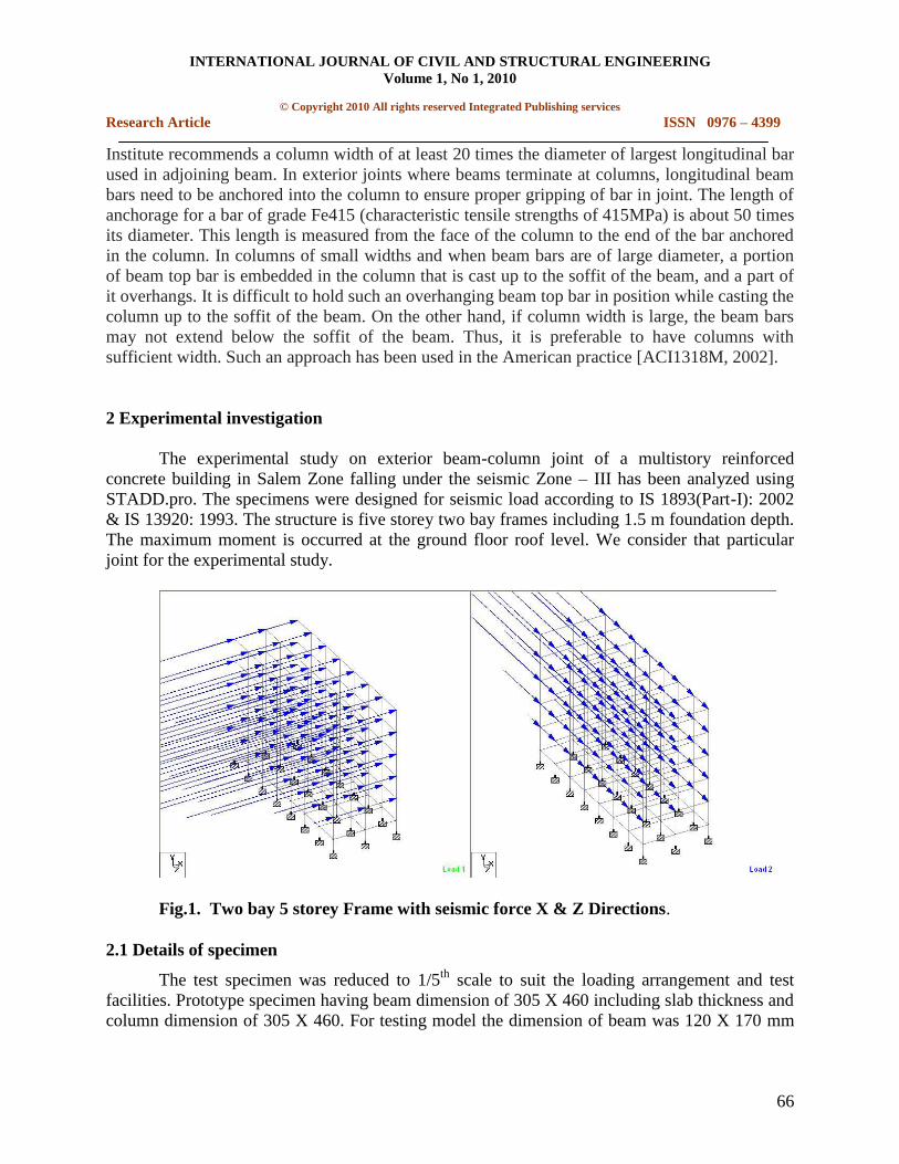
The experimental study on exterior beam-column joint of a multistory reinforced
concrete building in Salem Zone falling under the seismic Zone – III has been analyzed using
STADD.pro. The specimens were designed for seismic load according to IS 1893(Part-I): 2002
& IS 13920: 1993. The structure is five storey two bay frames including 1.5 m foundation depth.
The maximum moment is occurred at the ground floor roof level. We consider that particular
joint for the experimental study.
Fig.1. Two bay 5 storey Frame with seismic force X & Z Directions.
2.1 Details of specimen
The test specimen was reduced to 1/5th
scale to suit the loading arrangement and test
facilities. Prototype specimen having beam dimension of 305 X 460 including slab thickness and
column dimension of 305 X 460. For testing model the dimension of beam was 120 X 170 mm
INTERNATIONAL JOURNAL OF CIVIL AND STRUCTURAL ENGINEERING
Volume 1, No 1, 2010
© Copyright 2010 All rights reserved Integrated Publishing services
Research Article ISSN 0976 – 4399
67
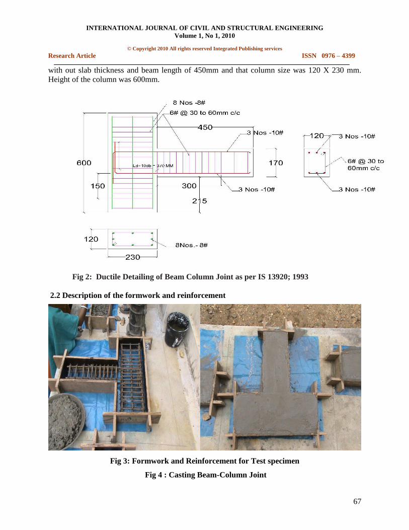
with out slab thickness and beam length of 450mm and that column size was 120 X 230 mm.
Height of the column was 600mm.
Fig 2: Ductile Detailing of Beam Column Joint as per IS 13920; 1993
2.2 Description of the formwork and reinforcement
Fig 3: Formwork and Reinforcement for Test specimen
Fig 4 : Casting Beam-Column Joint
INTERNATIONAL JOURNAL OF CIVIL AND STRUCTURAL ENGINEERING
Volume 1, No 1, 2010
© Copyright 2010 All rights reserved Integrated Publishing services
Research Article ISSN 0976 – 4399
68
2.3 Reinforcement details
The reinforcement details of beam column joint are shown in fig.2. Main reinforcement
provided in the beam was 10 mm diameter bars, 3 Nos at top and 3 Nos at bottom. The stirrups
are 6 mm diameter bars at 30 mm c/c for a distance of 2d, i.e. 300 mm from the face of the
column and at 60 mm c/c for remaining length of the beam. The longitudinal reinforcement
provided in the column was 8 No’s of 8 mm diameter bars equally distributed along four sides of
column. The column confinements are 6 mm diameter bars at 30 mm c/c for a distance of 150
mm from the face of the column and at 60 mm c/c for remaining length of the column.
2.4 Casting and curing
The mould is arranged properly and placed over a smooth surface. The sides of the mould
exposed to concrete were oiled well to prevent the side walls of the mould from absorbing water
from concrete and to facilitate easy removal of the specimen. The reinforcement cages were
placed in the moulds and cover between cage and form provided was 20 mm. Concrete mix
designed for M30 ( 1:1:2.5) and water cement ratio is 0.40. Cement mortar block pieces were
used as cover blocks. The concrete contents such as cement, sand, aggregate and water were
weighed accurately and mixed. The mixing was done till uniform mix was obtained. The
concrete was placed into the mould immediately after mixing and well compacted. Control cubes
and cylinders were prepared for all the mixes along with concreting. The test specimens were
remolded at the end of 24 hours of casting. They were marked identifications. They are cured in
water for 28 days. After 28 days of curing the specimen was dried in air and white washed.
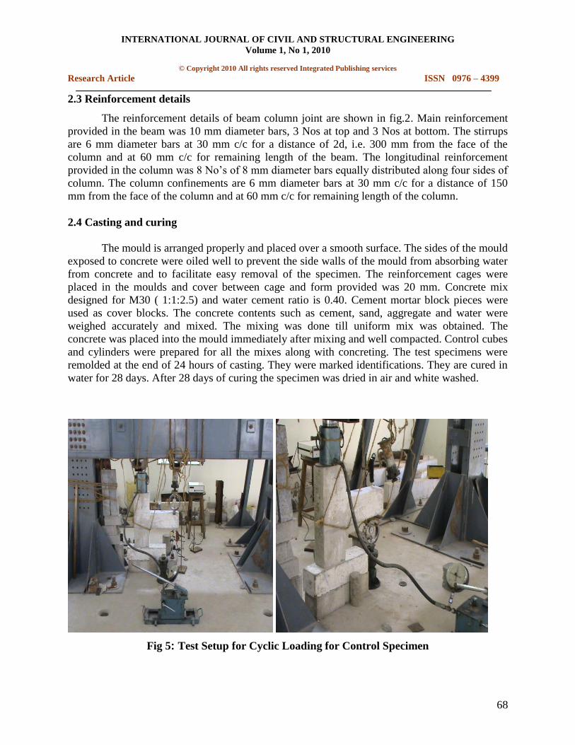
Fig 5: Test Setup for Cyclic Loading for Control Specimen
INTERNATIONAL JOURNAL OF CIVIL AND STRUCTURAL ENGINEERING
Volume 1, No 1, 2010
© Copyright 2010 All rights reserved Integrated Publishing services
Research Article ISSN 0976 – 4399
69
2.5 Test setup and instrumentation
The specimen was tested in a reaction frame. The test setup is shown in figure 4. A
hydraulic jack was used to apply the axial load for column. To record the load precisely a
proving ring was used. The load is applied forward cyclic and reverse cyclic and deflection
measured from every 3 KN by using LVDT. The deflection was measured at the beam free end
tip. Loading is applied gradually such as 3,6,9,12,15 KN respectively for forward direction and -
3,-6,-9,-12,-15 KN respectively for reverse direction.
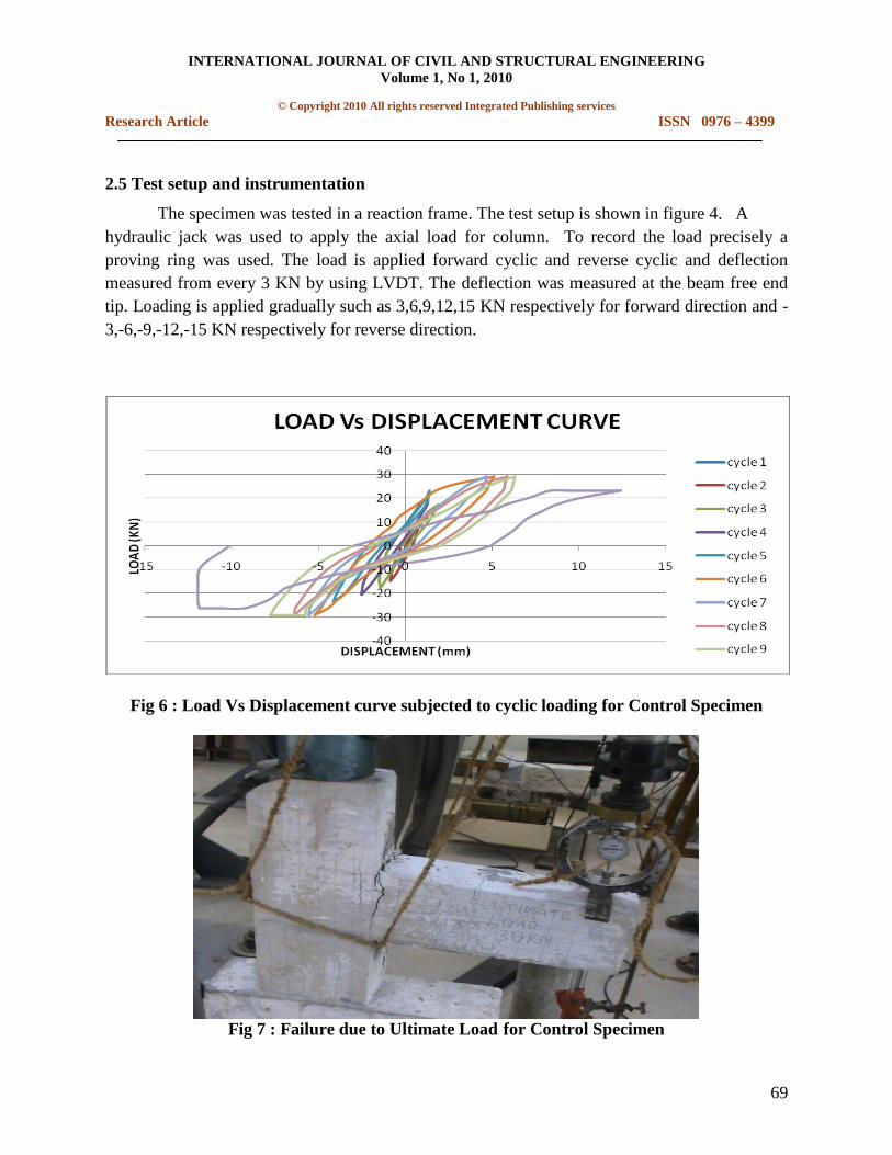
Fig 6 : Load Vs Displacement curve subjected to cyclic loading for Control Specimen
Fig 7 : Failure due to Ultimate Load for Control Specimen
INTERNATIONAL JOURNAL OF CIVIL AND STRUCTURAL ENGINEERING
Volume 1, No 1, 2010
© Copyright 2010 All rights reserved Integrated Publishing services
Research Article ISSN 0976 – 4399
70
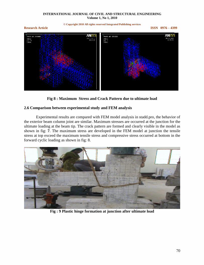
Fig 8 : Maximum Stress and Crack Pattern due to ultimate load
2.6 Comparison between experimental study and FEM analysis
Experimental results are compared with FEM model analysis in stadd.pro, the behavior of
the exterior beam column joint are similar. Maximum stresses are occurred at the junction for the
ultimate loading at the beam tip. The crack pattern are formed and clearly visible in the model as
shown in fig: 7. The maximum stress are developed in the FEM model at junction the tensile
stress at top exceed the maximum tensile stress and compressive stress occurred at bottom in the
forward cyclic loading as shown in fig: 8.
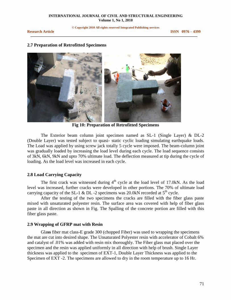
Fig : 9 Plastic hinge formation at junction after ultimate load
INTERNATIONAL JOURNAL OF CIVIL AND STRUCTURAL ENGINEERING
Volume 1, No 1, 2010
© Copyright 2010 All rights reserved Integrated Publishing services
Research Article ISSN 0976 – 4399
71
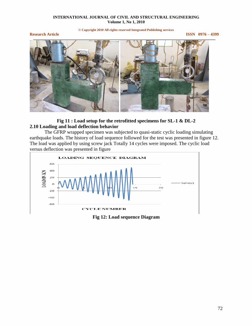
2.7 Preparation of Retrofitted Specimens
Fig 10: Preparation of Retrofitted Specimens
The Exterior beam column joint specimen named as SL-1 (Single Layer) & DL-2
(Double Layer) was tested subject to quasi- static cyclic loading simulating earthquake loads.
The Load was applied by using screw jack totally 5 cycle were imposed. The beam-column joint
was gradually loaded by increasing the load level during each cycle. The load sequence consists
of 3kN, 6kN, 9kN and upto 70% ultimate load. The deflection measured at tip during the cycle of
loading. As the load level was increased in each cycle.
2.8 Load Carrying Capacity
The first crack was witnessed during 4th
cycle at the load level of 17.0kN. As the load
level was increased, further cracks were developed in other portions. The 70% of ultimate load
carrying capacity of the SL-1 & DL -2 specimens was 20.0kN recorded at 5th
cycle.
After the testing of the two specimens the cracks are filled with the fiber glass paste
mixed with unsaturated polyester resin. The surface area was covered with help of fiber glass
paste in all direction as shown in Fig. The Spalling of the concrete portion are filled with this
fiber glass paste.
2.9 Wrapping of GFRP mat with Resin
Glass fiber mat class-E grade 300 (chopped Fiber) was used to wrapping the specimens
the mat are cut into desired shape. The Unsaturated Polyester resin with accelerator of Cobalt 6%
and catalyst of .01% was added with resin mix thoroughly. The Fiber glass mat placed over the
specimen and the resin was applied uniformly in all direction with help of brush. Single Layer
thickness was applied to the specimen of EXT-1, Double Layer Thickness was applied to the
Specimen of EXT -2. The specimens are allowed to dry in the room temperature up to 16 Hr.
INTERNATIONAL JOURNAL OF CIVIL AND STRUCTURAL ENGINEERING
Volume 1, No 1, 2010
© Copyright 2010 All rights reserved Integrated Publishing services
Research Article ISSN 0976 – 4399
72
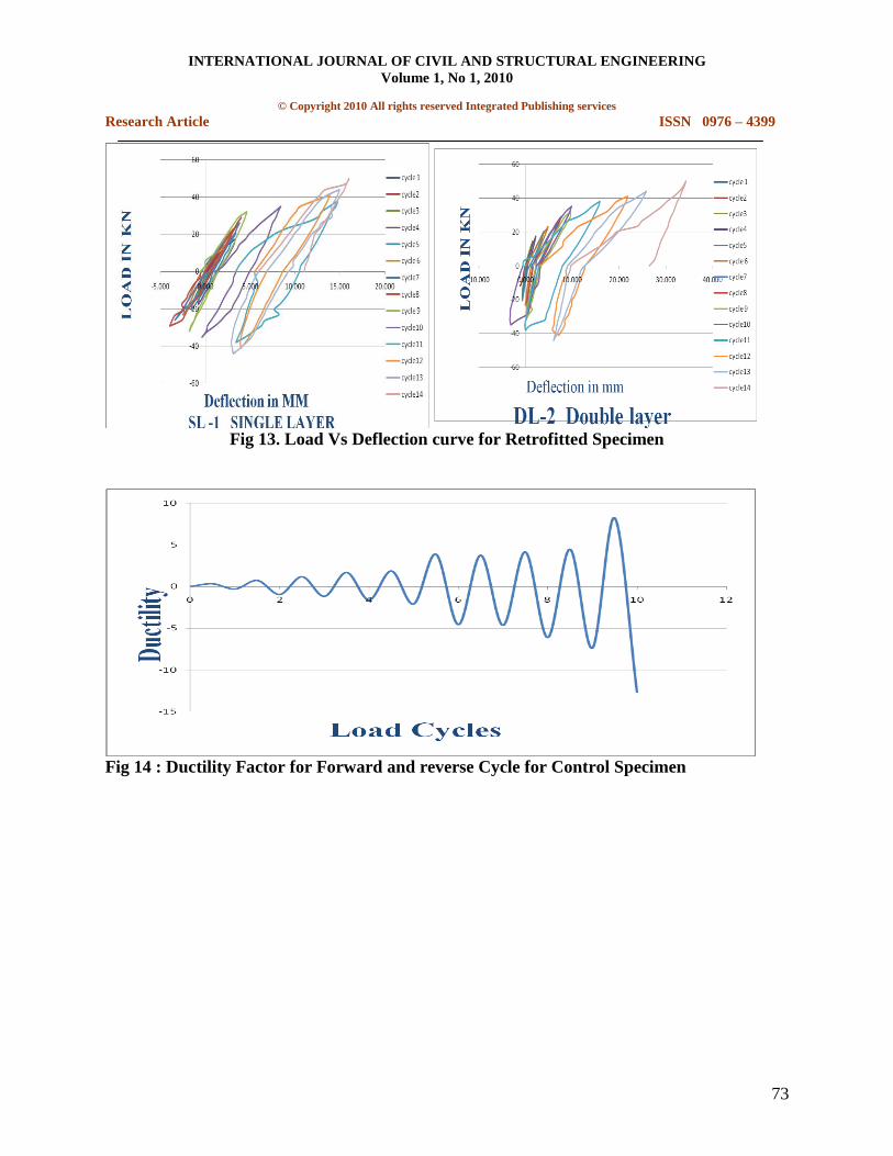
Fig 11 : Load setup for the retrofitted specimens for SL-1 & DL-2
2.10 Loading and load deflection behavior
The GFRP wrapped specimen was subjected to quasi-static cyclic loading simulating
earthquake loads. The history of load sequence followed for the test was presented in figure 12.
The load was applied by using screw jack Totally 14 cycles were imposed. The cyclic load
versus deflection was presented in figure
Fig 12: Load sequence Diagram
INTERNATIONAL JOURNAL OF CIVIL AND STRUCTURAL ENGINEERING
Volume 1, No 1, 2010
© Copyright 2010 All rights reserved Integrated Publishing services
Research Article ISSN 0976 – 4399
73
Fig 13. Load Vs Deflection curve for Retrofitted Specimen
Fig 14 : Ductility Factor for Forward and reverse Cycle for Control Specimen
INTERNATIONAL JOURNAL OF CIVIL AND STRUCTURAL ENGINEERING
Volume 1, No 1, 2010
© Copyright 2010 All rights reserved Integrated Publishing services
Research Article ISSN 0976 – 4399
74
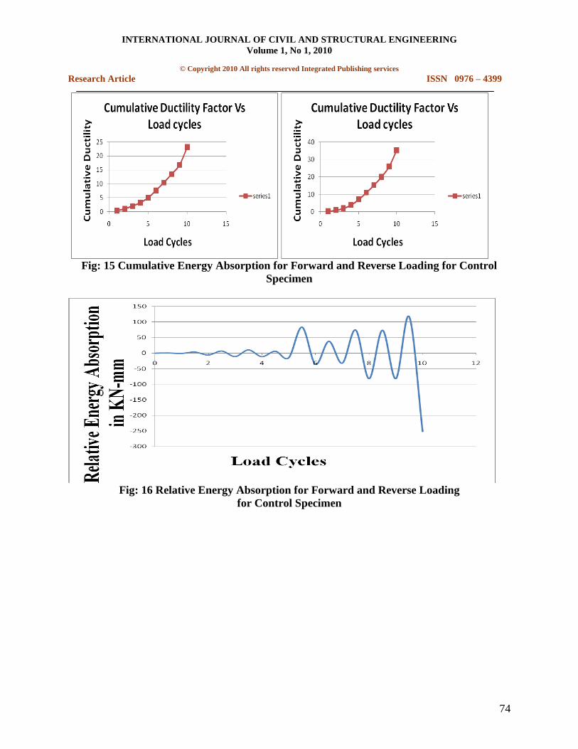
Fig: 15 Cumulative Energy Absorption for Forward and Reverse Loading for Control
Specimen
Fig: 16 Relative Energy Absorption for Forward and Reverse Loading
for Control Specimen
INTERNATIONAL JOURNAL OF CIVIL AND STRUCTURAL ENGINEERING
Volume 1, No 1, 2010
© Copyright 2010 All rights reserved Integrated Publishing services
Research Article ISSN 0976 – 4399
75
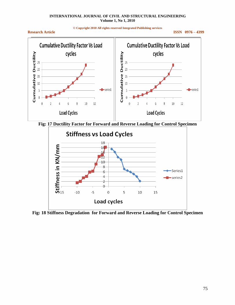
Fig: 17 Ductility Factor for Forward and Reverse Loading for Control Specimen
Fig: 18 Stiffness Degradation for Forward and Reverse Loading for Control Specimen
INTERNATIONAL JOURNAL OF CIVIL AND STRUCTURAL ENGINEERING
Volume 1, No 1, 2010
© Copyright 2010 All rights reserved Integrated Publishing services
Research Article ISSN 0976 – 4399
76
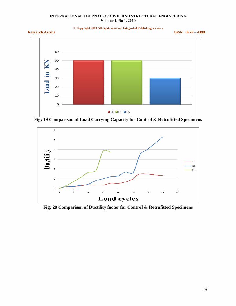
Fig: 19 Comparison of Load Carrying Capacity for Control & Retrofitted Specimens
Fig: 20 Comparison of Ductility factor for Control & Retrofitted Specimens
INTERNATIONAL JOURNAL OF CIVIL AND STRUCTURAL ENGINEERING
Volume 1, No 1, 2010
© Copyright 2010 All rights reserved Integrated Publishing services
Research Article ISSN 0976 – 4399
77
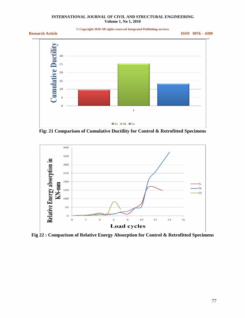
Fig: 21 Comparison of Cumulative Ductility for Control & Retrofitted Specimens
Fig 22 : Comparison of Relative Energy Absorption for Control & Retrofitted Specimens
INTERNATIONAL JOURNAL OF CIVIL AND STRUCTURAL ENGINEERING
Volume 1, No 1, 2010
© Copyright 2010 All rights reserved Integrated Publishing services
Research Article ISSN 0976 – 4399
78
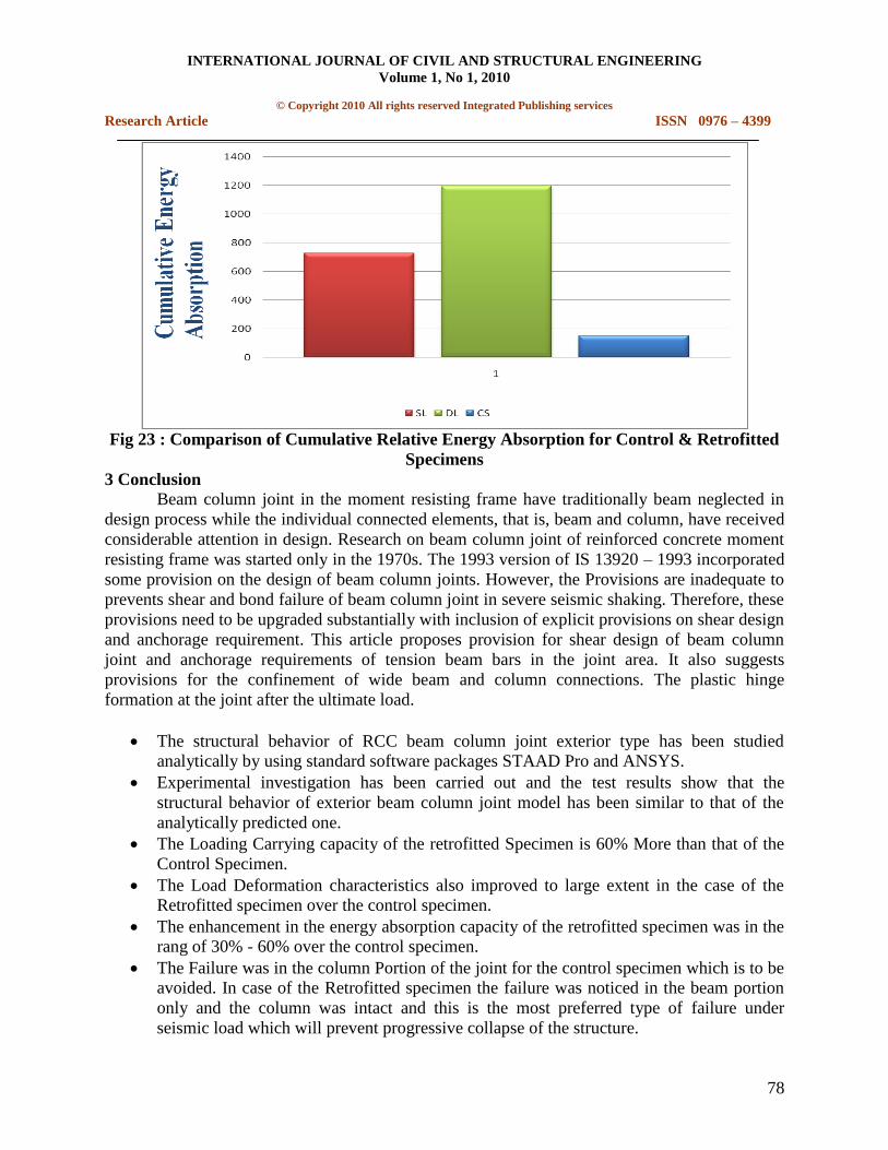
Fig 23 : Comparison of Cumulative Relative Energy Absorption for Control & Retrofitted
Specimens
3 Conclusion
Beam column joint in the moment resisting frame have traditionally beam neglected in
design process while the individual connected elements, that is, beam and column, have received
considerable attention in design. Research on beam column joint of reinforced concrete moment
resisting frame was started only in the 1970s. The 1993 version of IS 13920 – 1993 incorporated
some provision on the design of beam column joints. However, the Provisions are inadequate to
prevents shear and bond failure of beam column joint in severe seismic shaking. Therefore, these
provisions need to be upgraded substantially with inclusion of explicit provisions on shear design
and anchorage requirement. This article proposes provision for shear design of beam column
joint and anchorage requirements of tension beam bars in the joint area. It also suggests
provisions for the confinement of wide beam and column connections. The plastic hinge
formation at the joint after the ultimate load.
The structural behavior of RCC beam column joint exterior type has been studied
analytically by using standard software packages STAAD Pro and ANSYS.
Experimental investigation has been carried out and the test results show that the
structural behavior of exterior beam column joint model has been similar to that of the
analytically predicted one.
The Loading Carrying capacity of the retrofitted Specimen is 60% More than that of the
Control Specimen.
The Load Deformation characteristics also improved to large extent in the case of the
Retrofitted specimen over the control specimen.
The enhancement in the energy absorption capacity of the retrofitted specimen was in the
rang of 30% - 60% over the control specimen.
The Failure was in the column Portion of the joint for the control specimen which is to be
avoided. In case of the Retrofitted specimen the failure was noticed in the beam portion
only and the column was intact and this is the most preferred type of failure under
seismic load which will prevent progressive collapse of the structure.
INTERNATIONAL JOURNAL OF CIVIL AND STRUCTURAL ENGINEERING
Volume 1, No 1, 2010
© Copyright 2010 All rights reserved Integrated Publishing services
Research Article ISSN 0976 – 4399
79
4 Reference
1. Hung-Jen Lee and Si-Ying Yu “Cyclic Response of Exterior Beam-Column Joints with
Different Anchorage Methods” The ACI structural Journal, Title No.106-S32, May-
June 2009.
2. A.G.Tsonos, I.A.Tegos and G.Gr.Penelis “Seismic resistance of Type 2 Exterior Beam
column joints reinforced with inclined bars” The ACI structural Journal, Title No.89-
S1, Jan-Feb 1992.
3. G. Appa Rao, M.Mahajan, M.Gangaram and Rolf Eligehausen “Performance of non-
seismically designed RC beam column joints strengthened by various schemes
subjected to seismic loads”, Journal of structural engineering, V.35, No.1, Apr-May
2008, pp 52-58.
4. Murthy C.V.R, Durgesh C.Rai, K.K.Bajpai and Sudhir.K.jain, “Anchorage Details and
Joint Design in Seismic RC Frames”, the Indian Concrete Journal, April 2001, pp 274 –
280.
5. G.S.Thirugnanam “Ductile Behavior Of FRP Strengthened R.C Beams Subjected To
Cyclic Loading” IRTT Erode.
6. A.Murugesan and Dr.G.S.Thirugnanam “Ductile Behavior of Steel Fiber Reinforced
Concrete beam-column joints subjected to Cyclic loading”, National Conference on
Advances and Innovations in civil Engineering, Mepco Schlenk Engineering
College,Sivakasi (2009),pp 27-33.
7. A.Murugesan and Dr.G.S.Thirugnanam“Ductile behavior Reinforced Concrete Beam -
Column joints Subjected to Cyclic loading”, National Conference on Recent Advances
in Concrete, Steel and Composite Structures , I.R.T.T., Erode (2009),pp .118-135


![Experimental study on FRP-to-concrete bonded joints Research PhD/2004 Experimental... · Experimental study on FRP-to-concrete bonded joints ... tests, e.g. [11–15], double shear](https://img.pdfslide.us/doc/110x75/5ae735667f8b9a9e5d8ebd53/experimental-study-on-frp-to-concrete-bonded-research-phd2004-experimentalexperimental.jpg)