Embed Size (px)
Citation preview
Experimental study of ductility in hard chromium
electroplated coatings
J. Setien, I. Gorrochategui, L. Sanchez, J.1VP. Varona, F. Gutierrez-Solana
Departamento de Ciencia e Ingenieria del Terrenoy de los Materiales,
Universidad de Cantabria, Avda. Los Castros, s/n 39005 Santander,
Spain
Abstract
In this work the results obtained from the study of ductility in a hard chromium
coating electroplated onto the inner wall of a stainless steel ring are presented.
This ring represents the cross section of a pipe to be joined by interference, so it
will suffer thermal shock during assembly and will be subjected to high hoop
stresses in normal operating conditions.
In order to evaluate both the ductility and strength of electrodeposited chromium,
different types of specimens from the original coated part were machined and
tested in tensile and three and four points bending modes.
Ductility and strength in the coating are evaluated through the relationship
between the crack density in the coating, controlled by SEM, and the strains
reached in the base material during tests.
The possible loss of ductility in the coating due to the thermal shock has also
been studied. Some of the specimens have been subjected to a thermal shock
equivalent to the real one during assembly, and were mechanically tested to
simulate the final state of the assembled unit. These results are compared with
the initial ones from non heat treated specimens.
The results of this ductility study have been used to define the maximum
allowable strains in the pipe.
Transactions on Engineering Sciences vol 8, © 1995 WIT Press, www.witpress.com, ISSN 1743-3533
282 Surface Treatment Effects II
1 Introduction
This work is based on a study carried out on the ductility of a conventional hard
chromium electrolytic plating deposited onto the inner wall of a stainless steel
ring representing the cross section of a pipe that will be joined by interference.
This process is recommended for specific situations where conventional welding
cannot be used. The technique is fundamentally based on the fitting of one part
into another which has been previously heated. The expansion caused by the
increase in temperature of the receiving part permits the insertion of the other
element involved in the union. When the assembly cools down the contraction of
the previously heated element onto the other results in a very tight joint.
With the aim of protecting the elements involved in the union, the receiving
element is sometimes chromium plated. The hard chromium deposit used is
know to have good hardness and wear-resistance properties. This coating avoids
mechanical damage to the element principally during the assembly process, thus
demonstrating its significance in the success of the union. It is important to
know the ductility and adherence properties of the coating and then to determine
if any changes are caused in these properties by the characteristic thermal shock
produced during the assembly.
For classical chromium electrodeposits the admissible elastic modulus is around
150 GPa and the tensile strength is approximately 150 MPa. Nevertheless, there
are a great diversity of results. This is probably because of characteristic cracks
in the structure of the chromium deposits which could cause premature failure
during tests. In any case, all the results seem to show that the fracture of
chromium deposits takes place within the elastic regime and occurs at strains
lower than 0.1% [ 1]. For the purpose of this research different mechanical tests
were performed (tensile tests and three and four point bending tests) and some
of the specimens were subjected to a thermal shock equivalent to the in-service
one during assembly. The results were used in the definition of maximum
allowable strains in the pipe.
Transactions on Engineering Sciences vol 8, © 1995 WIT Press, www.witpress.com, ISSN 1743-3533

Surface Treatment Effects II 283
2 Available material
The available material was a 150 mm long ring, internal diameter 134 mm and
external diameter 148 mm. These dimensions are typical of thermal sleeves for
feedwater nozzles in BWR nuclear power stations.
The bulk material of the ring was austenitic stainless steel AISI 304 with the
following mechanical properties: 0.2% yield stress, Gy = 246 MPa and tensile
strength, GU = 564 MPa. The standard elastic modulus for this material is E =
203 GPa.
The hard chromium coating on the inner wall of the ring has been deposited by
conventional electrolysis from a classic chromic (250 g/1) and sulfuric (2.5 g/1)
acid bath at 52°C. The final average thickness of the coating measured by SEM
was around 40 |im. Vickers microhardness tests were performed on a cross
section of the coating applying loads of 100 g for 20 seconds. The average result
was 839 HVN. As will be shown later this extreme hardness is associated with
the high brittleness of these coatings.
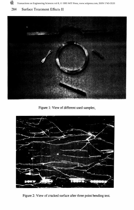
Because of the particular geometry of the element studied, the initial ring was cut
into non standaraised tensile and three and four points bending samples, as is
shown in Figure 1.
3 Experimental Procedure and Tests
The experimental methodology is based on the performance of tensile and three
and four point bending tests. Each of these tests are briefly described and
justified below.
3.1 Three point bending test
This is one of the most useful tests for studying the adherence of the coating to
the base material. The load applied onto the sample produces a tensile stress state
in the coating allowing the adherence to the base material to be evaluated.
Moreover, the inspection of the surface of the coating before and after the test
will provide information about its ductility. This is possible because of the
variation in crack density produced during the test.
In this way it was rapidly seen that the adherence of the coating is excellent. In
spite of the high level of plastic strain reached no generalized detachment of the
Transactions on Engineering Sciences vol 8, © 1995 WIT Press, www.witpress.com, ISSN 1743-3533
284 Surface Treatment Effects II
Figure 1: View of different used samples.
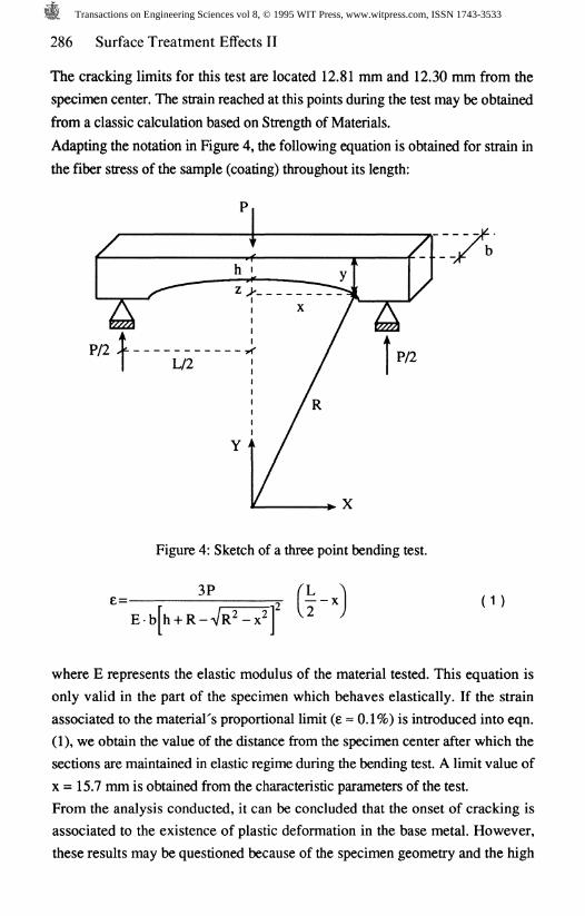
Figure 2: View of cracked surface after three point bending test.
Transactions on Engineering Sciences vol 8, © 1995 WIT Press, www.witpress.com, ISSN 1743-3533

Surface Treatment Effects II 285
coating was observed. Nevertheless, detailed SEM analysis showed a slight
flaking off at the edges of the tested sample.
Further observation of the coating's free surface showed the appearance of an
important number of tensile cracks as can be seen in the photograph in Figure 2.
The presence of these cracks gradually reduces with distance from the center of
the specimen, finally reaching areas where no additional cracking is discernible.
This logically demonstrates the existence of a cracking limit: below a certain
strain level the coating remains intact without generating new cracks.
Working with SEM at 200x the crack density could be quantified at various
distances from the center of the specimen. The number of crack intersections
crossing a defined reference line was measured. The number of cracks per unit
length represents the crack density. The variation of crack density obtained for
this test is represented in Figure 3.
Crack density (cracks/mm)
i-t K
* N>
10
dA
OL
nO
LA
OL
AC
, ,
, ,
1 ,
, ,
. 1
, .
. .
1 1
. .
i 1
1 1
1 I
1 I
< 1
i 1
1 1
I 1
-]
1 I 1 1 !
e * o
0 0 e
e o
e
eo o
0 0
1 1 1 1 15 - 1 0 - 5 0 5 1 0 1
Distance from center (mm)
Figure 3: Variation in crack density with distance from the specimen center in the
three point bending test.
Transactions on Engineering Sciences vol 8, © 1995 WIT Press, www.witpress.com, ISSN 1743-3533
286 Surface Treatment Effects II
The cracking limits for this test are located 12.81 mm and 12.30 mm from the
specimen center. The strain reached at this points during the test may be obtained
from a classic calculation based on Strength of Materials.
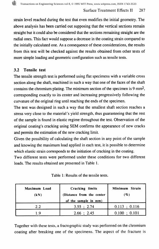
Adapting the notation in Figure 4, the following equation is obtained for strain in
the fiber stress of the sample (coating) throughout its length:
Figure 4: Sketch of a three point bending test.
e=-3P
x (1)
where E represents the elastic modulus of the material tested. This equation is
only valid in the part of the specimen which behaves elastically. If the strain
associated to the material's proportional limit (e « 0.1%) is introduced into eqn.
(1), we obtain the value of the distance from the specimen center after which the
sections are maintained in elastic regime during the bending test. A limit value of
x = 15.7 mm is obtained from the characteristic parameters of the test.
From the analysis conducted, it can be concluded that the onset of cracking is
associated to the existence of plastic deformation in the base metal. However,
these results may be questioned because of the specimen geometry and the high
Transactions on Engineering Sciences vol 8, © 1995 WIT Press, www.witpress.com, ISSN 1743-3533
Surface Treatment Effects II 287
strain level reached during the test that even modifies the initial geometry. The
above analysis has been carried out supposing that the vertical sections remain
straight but it could also be considered that the sections remaining straight are the
radial ones. This fact would suppose a decrease in the coating strain compared to
the initially calculated one. As a consequence of these considerations, the results
from this test will be checked against the results obtained from other tests of
more simple loading and geometric configuration such as tensile tests.
3.2 Tensile test
The tensile strength test is performed using flat specimens with a variable cross
section along the shaft, machined in such a way that one of the faces of the shaft
contains the chromium plating. The minimum section of the specimen is 9 mm^,
corresponding exactly to its center and increasing progressively following the
curvature of the original ring until reaching the ends of the specimen.
The test was designed in such a way that the smallest shaft section reaches a
stress very close to the material's yield strength, thus guaranteeing that the rest
of the sample is found in elastic regime throughout the test. Observation of the
original coating's cracking using SEM confirms the appearance of new cracks
and permits the estimation of the new cracking limit.
Given the possibility of calculating the shaft section in any point of the sample
and knowing the maximum load applied in each test, it is possible to determine
which elastic strain corresponds to the initiation of cracking in the coating.
Two different tests were performed under these conditions for two different
loads. The results obtained are presented in Table 1.
Table 1: Results of the tensile tests.
Maximum Load
(kN)
2.2
1.9
Cra
(Distance
of the
3.
2.
eking
from
sampl
55 ;
66 ;
limi
the
e in
2.74
2.45
ts
center
mm)
Mi
0
0
nimum
(%
113 ;
100 ;
S
)
0.
0.
train
116
101
Together with these tests, a fractographic study was performed on the chromium
coating after breaking one of the specimens. The aspect of the fracture is
Transactions on Engineering Sciences vol 8, © 1995 WIT Press, www.witpress.com, ISSN 1743-3533

288 Surface Treatment Effects II
presented in Figure 5. The photograph shows a frontal view of the fracture
surface. The coating can be seen to have separated into isolated islands with very
flat lateral surfaces, demonstrating very clean fragile fractures.
Figure 5: View of fracture surface in hard chromium coating.
3.3 Four point bending test
A four point bending test was designed to definitively check the experimental
procedure earned out up to this moment. The specimens used were obtained
from 120* arcs taken from the original ring. Rectilinear segments were welded to
the ends of these arcs, producing the shape shown at the top of Figure 1.
As the bending takes place at four points, the fundamental advantage of this test
lies in obtaining an isodeformation state throughout the coating. If the minimum
crack-producing strain is reached cracks should appear throughout the surface of
the coating providing a wide field of inspection.
In an attempt to reproduce the results obtained in the tensile test, a calculation
was made of the load necessary to produce a strain of e = 0.1% in all the
circumference of the arc. According to Strength of Materials, the said load is
obtained from the equation
Transactions on Engineering Sciences vol 8, © 1995 WIT Press, www.witpress.com, ISSN 1743-3533
6c
Surface Treatment Effects II 289
where b and h are the ring section dimensions and c is the separation between
two supports that produces opposing reactions. This expression is once again
derived from the hypothesis of Strength Materials and is only valid within the
elastic regime.
Reaching a load corresponding to a strain of 0.1% it is shown that cracks appear
uniformly distributed over the surface, thus confirming the results obtained from
the tensile tests.
Repeating the test in successive steps using ever-increasing strain levels, the
damage in the coating can be monitored to establish a validity criterion.
4 Effect of thermal shock
In order to exactly reproduce the service conditions of the element, some of the
samples were subjected to a thermal shock similar to that produced in the
assembly of the pipe.
This treatment consisted of introducing the samples into an oven at 280*C. The
samples were left in the oven long enough to uniformly reach this temperature.
The samples were then cooled in clean water and subjected to a tensile test
performed under the the same conditions as the untreated samples. The surfaces
of the coating were inspected before and after the thermal shock. In all cases no
apparent differences were observed. The cracking was inspected once again after
the test to locate the cracking limit and the corresponding strain was calculated
following the same method as before.
In all the cases studied the only visible effect was a light oxidation of the
stainless steel but no loss of ductility was noticed in the coating.
Therefore, apart from the accepted experimental error, no difference exits
between the cracking limit results obtained from the untreated and treated
samples, what's more, there is no difference in the type nor evolution of the
cracking with strain.
Transactions on Engineering Sciences vol 8, © 1995 WIT Press, www.witpress.com, ISSN 1743-3533
290 Surface Treatment Effects II
5 Discussion
The results presented until now clearly show that the adherence of the studied
coating is very good. However, the coating presents a very high brittleness
manifested by cracking when the element is mechanically loaded.
This cracking is induced even within the elastic regime of the base material. The
associated strains are as small as 0.1% which agrees with published
bibliography.
Also, the thermal shock does not produce any variation in the brittleness of the
coating. At high temperatures an important reduction in hardness is produced in
the coating along with generalized cracking during sudden cooling. This latter is
due to the difference between the thermal expansion coefficients of the base
material and the coating [2]. Nevertheless, at the temperatures considered in this
work it must be concluded that the process of union by interference has no effect
on the ductility and adherence properties of the coating.
Once the existence of damage in the coating has been established at very low
strain levels, it is advisable to analyse the importance of this damage on the
normal use of the coating. If the chromium demonstrates characteristic cracking
produced by electroplating process, then the addition of some new cracks of
mechanical origin may not be excessively important. This is especially relevant if
the assembly is not working in direct contact with any aggressive environment
which could affect the base material through the cracks.
It is therefore convenient to distinguish two types of damage to the coating. On
the one hand, damage of mechanical origin exists in the form of cracks very
similar to those typically produced in the coating at very low strain levels and
only observable using microscopic techniques. On the other hand, if strain
increases slightly, the critical values being between 0.15% and 0.2%, then
generalized cracking is produced throughout the surface of the coating causing
damage which should now be considered as important.
This overall damage is observable using 50x magnification and sometimes even
the naked eye, therefore it can be considered as macroscopic.
Finally it should be mentioned that the macroscopic damage is only produced if
plastic strains are reached in the base material. This is impossible in the normal
design of the assembly and the working conditions of these pipes. Therefore,
the high brittleness of the coating does not suppose an important problem to the
Transactions on Engineering Sciences vol 8, © 1995 WIT Press, www.witpress.com, ISSN 1743-3533
Surface Treatment Effects II 291
normal working of the assembly in this case because of the absence of
aggressive environments which could attack the stainless steel through the
cracks in the coating.
6 Conclusions
The results obtained in this work can be summarised as follows:
- The low ductility of conventional hard chromium electroplating causes
cracking at low strain levels (around 0.1%) corresponding to the elastic
regime of the base material.
As the assembly studied here is not in contact with aggressive environments
which could affect the base material through cracks in the coating, the
production of cracks by mechanical means (microscopic damage) is not very
relevant to the quality of the assembly.
- The generalized damage to the coating (macroscopic damage), produced at
strains around 0.2%, is characterised by open cracks throughout the surface
of the coating. This state is only reached when the base material has a certain
degree of plasticity which is avoided in the design of the element.
- The adherence of the coating to the base material can be classified as
excellent. Partial detachment only appears at the edges of the coating at very
high plastic strains which are unforeseeable in normal service.
- The normal shock suffered by the element during the process of joint by
interference does not affect the ductility and adherence properties of the
coating.
- The use of hard chromium electrolytic plating as a protection for elements
subjected to union by interference is perfectly admissible. This process does
not suppose any inconvenience to the normal working of the coating.
References
1. Morisset, P. Ghromage Dur et Dtcoratif, CETIM, 3̂ Edition, 1988.
2. Setien, J., Varona, J.M-, Gutierrez-Solana, F., & Sanchez, L. Variaciones
estructurales y de dureza en recubrimientos electroltticos de cromo duro
tratados t£rmicamente, Anales de Ingenieria Mecdnica, 1992, 5, 151-157.
Transactions on Engineering Sciences vol 8, © 1995 WIT Press, www.witpress.com, ISSN 1743-3533


![ASCERTAINMENT OF THE CHANGE OF THE DUCTILITY IN … · the processes of elongation or area reduction, while undergoing a tensile test [1-2]. Ductility is particularly important concerning](https://img.pdfslide.us/doc/110x75/5ebcb72f1c5055556849574a/ascertainment-of-the-change-of-the-ductility-in-the-processes-of-elongation-or-area.jpg)