Embed Size (px)
Citation preview
1
The Tensile Ductility of Cellular Solids: the Role of Imperfections
William Ronan1,2, Vikram S. Deshpande1 and Norman A.Fleck1*
1 Cambridge University Engineering Dept., Trumpington St., Cambridge, CB2 1PZ, UK
2 Present address: Mechanical Engineering, National University of Ireland Galway, Ireland
* Corresponding author
27 September 2016
Revised for International Journal of Solids and Structures
Abstract
Metallic and polymeric foams typically possess a low tensile failure strain of a few percent
despite the fact that the parent solid can have high ductility (10% or more). This is remarkable as
foams are bending-dominated in their structural response, and it is widely accepted that beams have
a high ductility in bending compared to a bar in uniaxial tension. Possible reasons for this paradox
are explored for a 2D hexagonal honeycomb, and for a so-called ‘lotus cellular material’, made
from an elastic-plastic parent solid. Finite element simulations reveal that there is only a small drop
in tensile ductility due to the presence of Plateau borders or due to the random misalignment of
nodes; a much greater drop in ductility results from missing cell walls (equivalent to misshapen
cells) or to the presence of stiff inclusions. The drop in ductility due to inclusions is associated with
the multi-axial stress state that exists in their vicinity. This study emphasises the need for a uniform
microstructure in order for foams to possess a high macroscopic ductility.
KEYWORDS
Cellular foams, Elastic plastic solids, Finite element, Foam structures, Micro-mechanics, Stress
strain, Tension
2
1 INTRODUCTION
Natural and synthetic foams, such as balsa wood and PVC foams, enjoy widespread application
as the load-bearing core of sandwich structures. Commonly, a sandwich beam or plate carries the
macroscopic force resultants of bending moment and shear force; through-thickness, multi-axial
stress states also arise at joints and under indentation loading, for example. Whilst the compressive
behaviour of foams has been extensively investigated, only a limited literature exists on the failure
of foams under tensile loading despite the fact that foam-cored beams can fail by tensile tearing of
the outermost fibre of the foam core. Remarkably, the observed tensile ductility of low density
metallic and polymeric foams is much less than that of the parent solid despite the fact that the cell
walls bend at a low strain amplitude under macroscopic tensile straining, as discussed by Gibson
and Ashby (1999). The main focus of this study is to account for this observation.
1.1 Property-microstructure relations
Analytical and numerical investigations have explored the relationship between the
microstructure of foams and lattices and their mechanical properties, see for example the pioneering
and comprehensive monograph of Gibson and Ashby (1999) for early developments and Goodall
and Mortensen (2014) for a more recent review.
Commonly, metallic and polymeric foams are manufactured by the solidification of a liquid
foam, with the foam geometry close to that of a low surface energy topology, such as the Kelvin
foam or Weaire-Phelan foam (Weaire and Hutzler, 2001). The minimisation of surface energy
leads to a low nodal connectivity of the open-cell micro-architecture, with a co-ordination number
of 3 to 4, see for example, Deshpande and Fleck (2001) and Deshpande et al. (2001). Recall that the
structural properties (eg stiffness and strength) of an open-cell foam closely resemble those of a
rigid-jointed frame. In turn, the structural properties of a rigid-jointed frame are inherited from
those of the parent pin-jointed truss. A co-ordination number of at least 6 in 3D (and at least 4 in
2D) is needed in order for the pin-jointed parent truss to be ‘simply stiff’, and for the beam-frame to
be stretching-dominated. A lower co-ordination number gives rise to a truss with collapse
mechanisms and to a bending-dominated beam-frame. Since a foam has a low co-ordination
number, it is bending-dominated in its structural response, and possesses a modulus, strength and
fracture toughness that scale with relative density to a power that exceeds unity, see Fleck et al.
(2010).
The mechanical properties of foams are only slightly knocked-down by geometric
imperfections in the form of Plateau borders, the random movement of nodes, and missing or wavy
3
cell-walls, as shown by a numerous studies largely done on 2D foams; see for example Simone and
Gibson (1998), Chen et al. (1999), Zhu et al. (2001) and more recent work by Fleck and co-workers
(Fleck and Qiu, 2007; Romijn and Fleck, 2007) that include the effect of cracks within the foams.
The broad conclusions drawn from the 2D studies extend to the 3D setting of open-celled foams as
generated by a Voronoi tessellation of randomly distributed points in 3D (Gan et al., 2005) and
perturbed Kelvin foams (Jang and Kyriakides, 2009; Jang et al., 2010). Song et al. (2010) further
extended these studies to closed celled foams and demonstrated that 3D Voronoi foams with facets
have a compressive strength that is approximately 60% higher than that of an open cell foam
comprising regular tetrakaidecahedrons and of equal relative density.
The above-mentioned studies are restricted to small deformations (e.g. modulus, initial
yield). A very limited number of numerical investigations on the large deformation of foams have
been reported to-date and they have all been restricted to compressive loading. For example,
Triantafyllidis and Schraad (1998) used analytical and finite element techniques to identify
bifurcations in the compressive response of hexagonal honeycombs and associated these
bifurcations with the onset of failure. This study was complimented by detailed finite element
calculations of bifurcations as reported by Gong and Kyriakides (2005) and Jang and Kyriakides
(2009).
1.2 Experimental observations on the compressive and tensile response of foams
A large number of experimental investigations have been reported on the compressive
response of foams and 2D cellular solids such as honeycombs. For example, Papka and Kyriakides
(1994; 1998) showed that the compressive deformation of hexagonal honeycombs occurs by the
successive crushing of rows of cells (via buckling and bending of the struts). The experimental
studies of Andrew et al. (1999) and Gong et al. (2005), amongst others, have demonstrated that this
compressive deformation mechanism also exists in 3D foams. These experimental findings confirm
the bifurcations and instabilities as predicted by Triantafyllidis and Schraad (1998) and Gong and
Kyriakides (2005).
In contrast, experimental investigations on the deformation and failure mechanisms of foams
under tensile loading are limited. The early analytical models of Gibson and Ashby (1999) suggest
that the cell-walls of 2D and 3D foams bend and align with the macroscopic direction of strain and
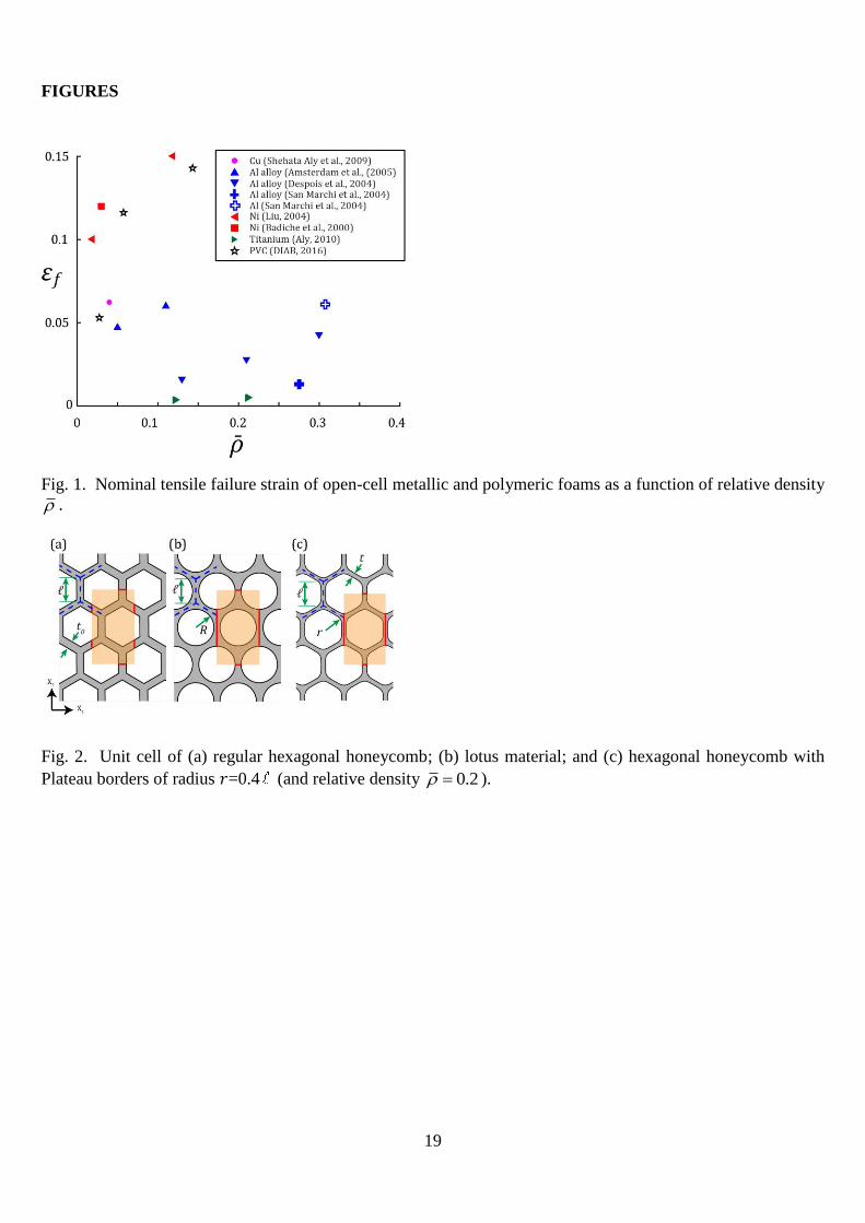
therefore should exhibit a macroscopic ductility that exceeds that of the parent solid. In reality, the
tensile ductility of open-celled metallic and polymeric foams is below that of the solid material, see
Fig.1. Over the practical range of relative density, the ductility of metallic foams is in the range 0.01

4
to 0.15, with the higher ductility associated with foams made from annealed metals of high
ductility. In contrast, the tensile ductility of the parent solid is on the order of 0.1-0.3.
A possible source of the reduced ductility in foams is the embrittlement at grain boundaries
due to segregation during the foaming process. In support of this mechanism, Amsterdam et al.
(2005) and San Marchi et al. (2004) observed both brittle (and ductile) fracture surfaces in the cell
walls of an open cell Al foam. However, an alternative reason for reduced ductility must exist for a
foam made from a pure metal. For example, Ochiai et al. (2010a, b) observed that the ductility of a
pure nickel foam is much less than that of the solid, and also noted that cell wall failure in the foam
was always ductile in nature. This points to a geometric cause such as the foam topology or to the
presence of imperfections within the foam as the source of reduced ductility.
1.3 Prediction of tensile failure of foams
In contrast to studies on the compressive loading of foams, numerical studies on the
relationship between macroscopic tensile ductility and microstructure of foams, including the role
of relative density, are limited. The main studies are those of Onck and co-workers (Mangipudi and
Onck, 2011, 2012). They modelled the tensile failure of 2D Voronoi foams by including a damage
model into the material description for the cell walls. This approach is best suited to model foams
containing brittle phases (such as the Al foams investigated by Amsterdam et al. (2005)) and the
model precludes tensile necking of the struts. In the present scoping study we aim to determine the
relationship between microstructure and macroscopic ductility for foams that fail by tensile necking
of the cell walls.
1.4 Scope of study
The relationship between microstructure, tensile ductility and ultimate tensile strength (UTS) of
two dimensional (2D) elasto-plastic foams is predicted by the finite element method for a wide
range of relative density. We begin by defining the cellular solid geometries: regular and irregular
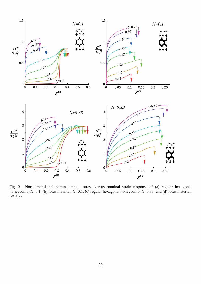
honeycombs, and “lotus material”, as defined in Fig. 2. The following imperfections are considered:
random repositioning of nodes, missing cell walls and the presence of an inclusion by in-filling of
one or more cells. The sensitivity of ductility and Ultimate Tensile Strength (UTS) to each
imperfection is assessed. Finally, the dependence of ductility upon macroscopic stress state is
explored.
5
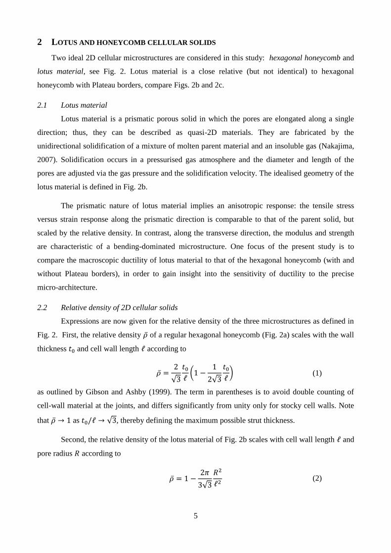
2 LOTUS AND HONEYCOMB CELLULAR SOLIDS
Two ideal 2D cellular microstructures are considered in this study: hexagonal honeycomb and
lotus material, see Fig. 2. Lotus material is a close relative (but not identical) to hexagonal
honeycomb with Plateau borders, compare Figs. 2b and 2c.
2.1 Lotus material
Lotus material is a prismatic porous solid in which the pores are elongated along a single
direction; thus, they can be described as quasi-2D materials. They are fabricated by the
unidirectional solidification of a mixture of molten parent material and an insoluble gas (Nakajima,
2007). Solidification occurs in a pressurised gas atmosphere and the diameter and length of the
pores are adjusted via the gas pressure and the solidification velocity. The idealised geometry of the
lotus material is defined in Fig. 2b.
The prismatic nature of lotus material implies an anisotropic response: the tensile stress
versus strain response along the prismatic direction is comparable to that of the parent solid, but
scaled by the relative density. In contrast, along the transverse direction, the modulus and strength
are characteristic of a bending-dominated microstructure. One focus of the present study is to
compare the macroscopic ductility of lotus material to that of the hexagonal honeycomb (with and
without Plateau borders), in order to gain insight into the sensitivity of ductility to the precise
micro-architecture.
2.2 Relative density of 2D cellular solids
Expressions are now given for the relative density of the three microstructures as defined in
Fig. 2. First, the relative density �̅� of a regular hexagonal honeycomb (Fig. 2a) scales with the wall
thickness 𝑡0 and cell wall length ℓ according to
�̅� =
2
√3
𝑡0
ℓ(1 −
1
2√3
𝑡0
ℓ) (1)
as outlined by Gibson and Ashby (1999). The term in parentheses is to avoid double counting of
cell-wall material at the joints, and differs significantly from unity only for stocky cell walls. Note
that �̅� → 1 as 𝑡0/ℓ → √3, thereby defining the maximum possible strut thickness.
Second, the relative density of the lotus material of Fig. 2b scales with cell wall length ℓ and
pore radius 𝑅 according to
�̅� = 1 −
2𝜋
3√3
𝑅2
ℓ2 (2)
6
Note that the thickness of cell wall vanishes at mid-length of the unit cell when the pore radius
approaches the value 𝑅/ℓ → √3/2, and the corresponding value of relative density is �̅� = 1 −
𝜋/(2√3) ≈ 0.093.
And third, recall that the Plateau borders of the hexagonal honeycomb are idealised by
enlarged nodes with a local radius of curvature 𝑟, see Fig. 2c. Geometry dictates that the relative
density is given by
�̅� =
2
√3
𝑡
ℓ−
1
3(
𝑡
ℓ)
2
+ (1
3−
2𝜋
3√3) (
𝑟
ℓ)
2
(3)
3 MODELLING APPROACH
For both the hexagonal honeycomb and lotus material, a representative volume element (RVE)
is considered, with the size of the RVE dependent upon the problem in hand. For ideal
microstructures, with no random variation from cell to cell, it suffices to consider one quarter of the
unit cell as the RVE. In contrast, imperfections in the form of randomly moved nodes necessitate a
much bigger RVE involving many cells.
Periodic boundary conditions are applied to the RVE such that the displacement jump Δ𝑈𝑖 on
opposite boundaries of the RVE is given by
Δ𝑈𝑖 = 𝜀𝑖𝑗∞Δ𝑋𝑗 (4)
where 𝜀𝑖𝑗∞ is the remote or macroscopic nominal strain and 𝑋𝑗 is the Cartesian co-ordinate system in
the reference configuration. The nominal strain 𝜀𝑖𝑗∞ is work-conjugate to the remote nominal stress
𝜎𝑖𝑗∞.
A finite element mesh is generated for the RVE geometry using four-noded, reduced-
integration plane-strain elements (CPE4R in ABAQUS element notation), with each strut
containing typically 10 elements across its thickness and 50 elements along its length. A Ramberg-
Osgood strain hardening law is used for the parent solid material, such that the true stress 𝜎 versus
true strain 𝜀 response is given by
ε
ε0s=
𝜎
𝜎0𝑠 + (
𝜎
𝜎0𝑠)
1𝑁
(5)
where ε0s = 0.001 is the yield strain, 𝜎0𝑠 is the yield strength and 𝑁 is the strain hardening
exponent. Unless otherwise stated, we shall assume 𝑁=0.1 in our numerical simulations. The
Ramberg-Osgood material model is implemented in the finite element scheme using 𝐽2 flow theory
7
and the usual finite strain assumptions. A macroscopic strain is imposed on the RVE as stipulated in
(4), and the finite element problem is solved using an implicit method (ABAQUS\Standard)1.
4 TENSILE RESPONSE OF REGULAR HONEYCOMB AND LOTUS MATERIAL
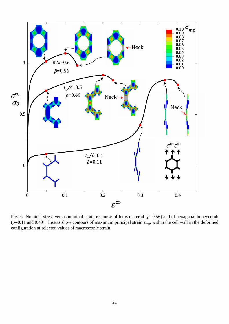
The macroscopic nominal stress versus strain response of the ideal hexagonal honeycomb and
lotus material are shown in Figs. 3a and b, respectively, for N=0.1 and in Fig. 3c and d,
respectively, for N=0.33. The predicted response is given for a wide range of relative density
0.01 < 𝜌 ̅ < 0.80, characteristic of an open-cell foam rather than a distribution of isolated voids.
Recall that the hexagonal honeycomb exists down to vanishing relative density, whereas the side
walls of the lotus material have vanishing thickness at the limiting value 𝜌 ̅ ≈ 0.11. There is a
dramatic switch in macroscopic response of the hexagonal honeycomb (Figs. 3a, c) at 𝜌 ̅ ≈ 0.3, as
follows. For 𝜌 ̅ < 0.3, the macroscopic tensile response has a distinct plateau in stress prior to a
steeply rising lock-up behaviour, followed by tensile necking at a macroscopic strain of 𝜀∞ ≈ 0.4
for N=0.1 and 𝜀∞ ≈ 0.55 for N=0.33 (as indicated by the downward vertical arrow on each curve).
In contrast, for 𝜌 ̅ > 0.3, the macroscopic tensile response resembles that of the parent solid, with
cell-wall necking occurring at a macroscopic nominal strain of 𝜀∞ ≈ 0.1 for N=0.1 and 𝜀∞ ≈ 0.3
for N=0.33, which is close to the nominal necking strain of the parent solid: 0.11 for N=0.1 and
0.39 for N=0.33. On the other hand, the lotus material has a stress versus strain response resembling
that of the parent solid for all values of relative density, with tensile failure occurring by necking at
a macroscopic nominal strain of approximately 0.13 for N=0.1 and 0.25 for N=0.33. In broad terms,
the macroscopic ductility of the hexagonal honeycomb, lotus material and parent solid increase by
approximately 0.2 when 𝑁 is increased from 0.1 to 0.33.
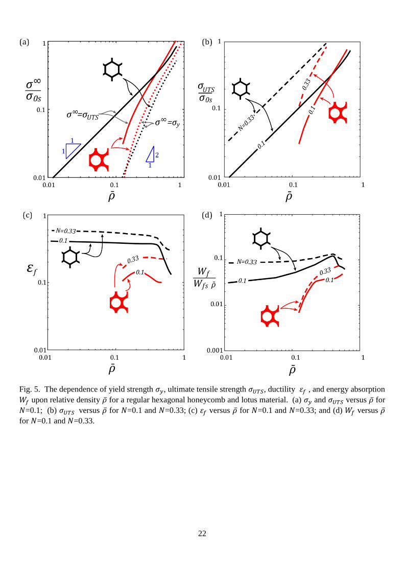
It is instructive to examine in detail the deformation of the hexagonal honeycomb and lotus
material, see Fig. 4. We choose for illustration a hexagonal honeycomb of low and high relative
density (�̅�=0.11 and 0.49, respectively) and a lotus material of high relative density (�̅�=0.56); the
strain hardening exponent is 𝑁 =0.1 in all three cases. Contours of maximum principal strain 𝜀𝑚𝑝
within the cell wall are shown at selected values of macroscopic strain.
First, consider the hexagonal honeycomb of low relative density, �̅�=0.11. Four distinct
deformation mechanisms occur in the following sequence with increasing level of remote strain:
i. Elastic bending of inclined cell walls;
ii. Plastic bending of inclined struts, with plastic zones at the joints;
1 Abaqus\Standard, version 6.14.2. Dassault Systèmes Simulia, RI, United States
8
iii. Geometric hardening by rotation of the inclined cell walls until all cell walls align with the
macroscopic loading direction; and
iv. Plastic stretching and then necking of the cell walls.
Within phase (ii) of plastic bending, the level of local tensile strain near the vertices of the
honeycomb exceeds the Considere necking strain of the parent solid but the cell walls remain stable.
In contrast, after axial alignment of the struts, the vertical cell walls stretch in phase (iv) until they
attain the uniaxial necking strain of the bulk material and necking ensues.
Second, consider the tensile response of the hexagonal honeycomb of higher relative density
(�̅�=0.49). This microstructure lies mid-way between the asymptotic limits of a hexagonal beam-
frame and a solid with a hexagonal distribution of voids. No plateau in macroscopic tensile response
is observed, and the shape of the stress-strain response of the hexagonal honeycomb resembles that
of the fully dense solid. Upon tensile loading, plastic straining is concentrated in the inclined walls
at low applied strain levels, and then switches to the vertical walls; necking occurs in the vertical
walls, as shown by the strain contours at selected stages of deformation.
Third, consider the lotus material. The large variation in cross-section along each cell wall
amplifies the axial strain at the thinnest section: necking of the vertical cell walls of the lotus
material occurs at a relatively low macroscopic strain (ie ductility) of 10% to 15%.
The dependence of macroscopic yield strength 𝜎𝑦 and ultimate tensile strength 𝜎𝑈𝑇𝑆 upon 𝜌 ̅
is plotted in Fig. 5a for the hexagonal honeycomb (absent Plateau borders) and for the lotus
material, where the yield strength has been identified at 0.2% offset plastic strain. Attention is
limited to the choice N=0.1. The effect of strain hardening exponent N on the UTS for both
materials is shown in Fig. 5b. The yield strength scales as �̅�2 for both topologies, consistent with
the well-known Gibson and Ashby (1999) result for a bending-dominated 2D microstructure. In
contrast, 𝜎𝑈𝑇𝑆 scales with 𝜌 ̅; this is consistent with the fact that that the vertical cell walls of the
hexagonal honeycomb are in a state of stretching at the onset of necking. This difference in scaling
with 𝜌 ̅ implies a difference in yield strength and UTS by almost an order of magnitude at �̅� = 0.1.
The response of the lotus material is more complex and 𝜎𝑈𝑇𝑆 scales approximately with �̅�2,
consistent with the following two observations: (i) the ratio of ligament thickness to cell size 𝑡/ℓ
scales approximately as �̅�2; and (ii), at the onset of necking, the lattice is in a state of stretching.
The macroscopic nominal failure strain 𝜀𝑓 of both lattices is summarised in Fig. 5c as a
function of �̅� for both N=0.1 and N=0.33. Note that the macroscopic ductility of the hexagonal
honeycomb is insensitive to 𝜌 ̅ up to 𝜌 ̅=0.4, then drops steeply with increasing 𝜌 ̅ and tends towards
9
the ductility of the parent solid. In contrast, the lotus material has a much lower ductility than that of
the hexagonal honeycomb, with a mild peak in 𝜀𝑓 at 𝜌 ̅ = 0.2. We conclude that the macroscopic
ductility of the 2D foam is sensitive to the precise details of micro-architecture.
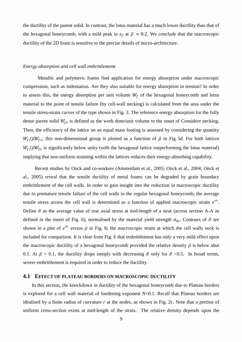
Energy absorption and cell wall embrittlememt
Metallic and polymeric foams find application for energy absorption under macroscopic
compression, such as indentation. Are they also suitable for energy absorption in tension? In order
to assess this, the energy absorption per unit volume 𝑊𝑓 of the hexagonal honeycomb and lotus
material to the point of tensile failure (by cell-wall necking) is calculated from the area under the
tensile stress-strain curves of the type shown in Fig. 3. The reference energy absorption for the fully
dense parent solid 𝑊𝑓𝑠 is defined as the work done/unit volume to the onset of Considere necking.
Then, the efficiency of the lattice on an equal mass footing is assessed by considering the quantity
𝑊𝑓/�̅�𝑊𝑓𝑠; this non-dimensional group is plotted as a function of �̅� in Fig 5d. For both lattices
𝑊𝑓/�̅�𝑊𝑓𝑠 is significantly below unity (with the hexagonal lattice outperforming the lotus material)
implying that non-uniform straining within the lattices reduces their energy-absorbing capability.
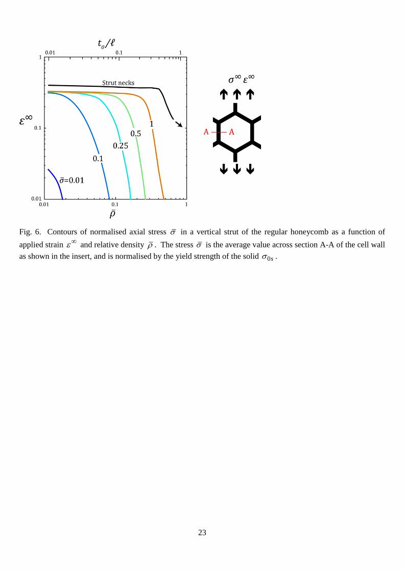
Recent studies by Onck and co-workers (Amsterdam et al., 2005; Onck et al., 2004; Onck et
al., 2005) reveal that the tensile ductility of metal foams can be degraded by grain boundary
embrittlement of the cell walls. In order to gain insight into the reduction in macroscopic ductility
due to premature tensile failure of the cell walls in the regular hexagonal honeycomb, the average
tensile stress across the cell wall is determined as a function of applied macroscopic strain 𝜀∞.
Define 𝜎 as the average value of true axial stress at mid-length of a strut (across section A-A as
defined in the insert of Fig. 6), normalised by the material yield strength 𝜎0𝑠. Contours of 𝜎 are
shown in a plot of 𝜀∞ versus �̅� in Fig. 6; the macroscopic strain at which the cell walls neck is
included for comparison. It is clear from Fig. 6 that embrittlement has only a very mild effect upon
the macroscopic ductility of a hexagonal honeycomb provided the relative density �̅� is below abut
0.1. At �̅� = 0.1, the ductility drops steeply with decreasing 𝜎 only for 𝜎 <0.5. In broad terms,
severe embrittlement is required in order to reduce the ductility.
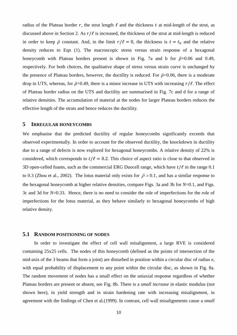
4.1 EFFECT OF PLATEAU BORDERS ON MACROSCOPIC DUCTILITY
In this section, the knockdown in ductility of the hexagonal honeycomb due to Plateau borders
is explored for a cell wall material of hardening exponent N=0.1. Recall that Plateau borders are
idealised by a finite radius of curvature r at the nodes, as shown in Fig. 2c. Note that a portion of
uniform cross-section exists at mid-length of the struts. The relative density depends upon the
10
radius of the Plateau border 𝑟, the strut length ℓ and the thickness 𝑡 at mid-length of the strut, as
discussed above in Section 2. As 𝑟/ℓ is increased, the thickness of the strut at mid-length is reduced
in order to keep �̅� constant. And, in the limit 𝑟/ℓ = 0, the thickness is 𝑡 = 𝑡0 and the relative
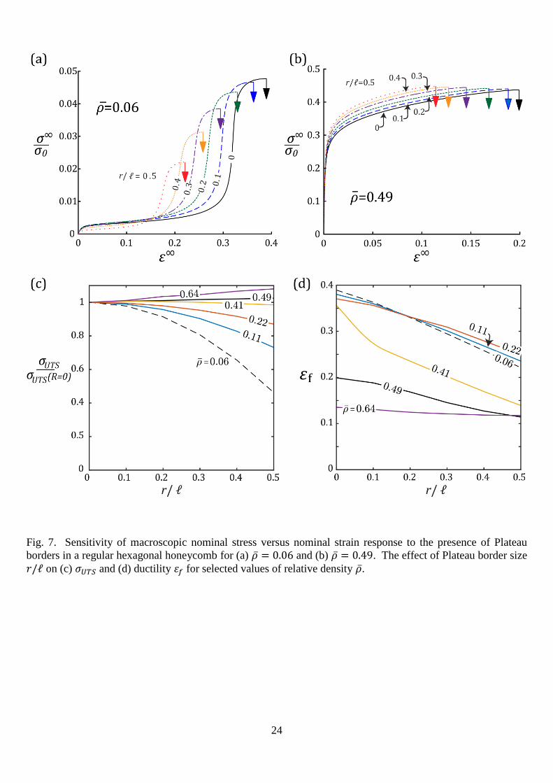
density reduces to Eqn (1). The macroscopic stress versus strain response of a hexagonal
honeycomb with Plateau borders present is shown in Fig. 7a and b for �̅�=0.06 and 0.49,
respectively. For both choices, the qualitative shape of stress versus strain curve is unchanged by
the presence of Plateau borders, however, the ductility is reduced. For �̅�=0.06, there is a moderate
drop in UTS, whereas, for �̅�=0.49, there is a minor increase in UTS with increasing 𝑟/ℓ. The effect
of Plateau border radius on the UTS and ductility are summarised in Fig. 7c and d for a range of
relative densities. The accumulation of material at the nodes for larger Plateau borders reduces the
effective length of the struts and hence reduces the ductility.
5 IRREGULAR HONEYCOMBS
We emphasise that the predicted ductility of regular honeycombs significantly exceeds that
observed experimentally. In order to account for the observed ductility, the knockdown in ductility
due to a range of defects is now explored for hexagonal honeycombs. A relative density of 22% is
considered, which corresponds to 𝑡/ℓ = 0.2. This choice of aspect ratio is close to that observed in
3D open-celled foams, such as the commercial ERG Duocell range, which have 𝑡/ℓ in the range 0.1
to 0.3 (Zhou et al., 2002). The lotus material only exists for 0.1 , and has a similar response to
the hexagonal honeycomb at higher relative densities, compare Figs. 3a and 3b for N=0.1, and Figs.
3c and 3d for N=0.33. Hence, there is no need to consider the role of imperfections for the role of
imperfections for the lotus material, as they behave similarly to hexagonal honeycombs of high
relative density.
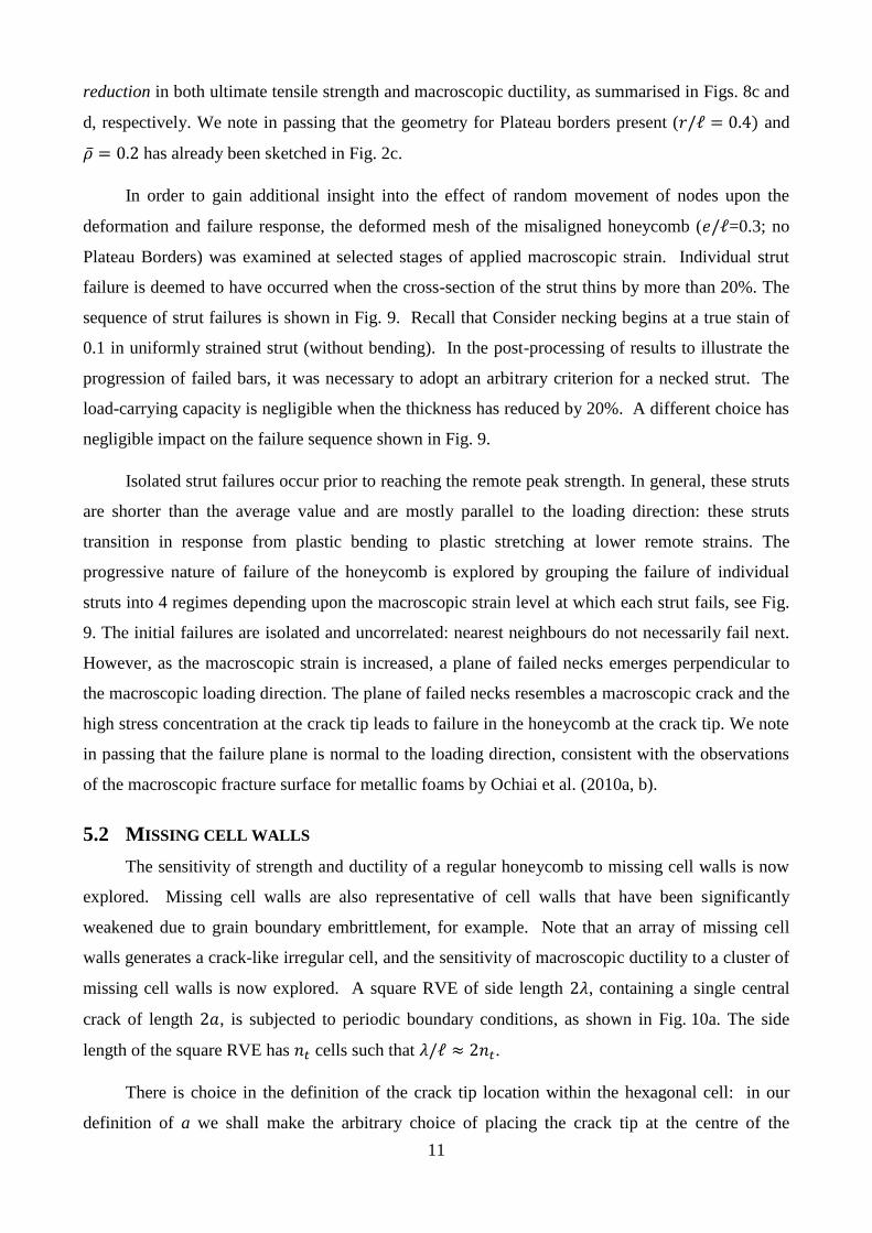
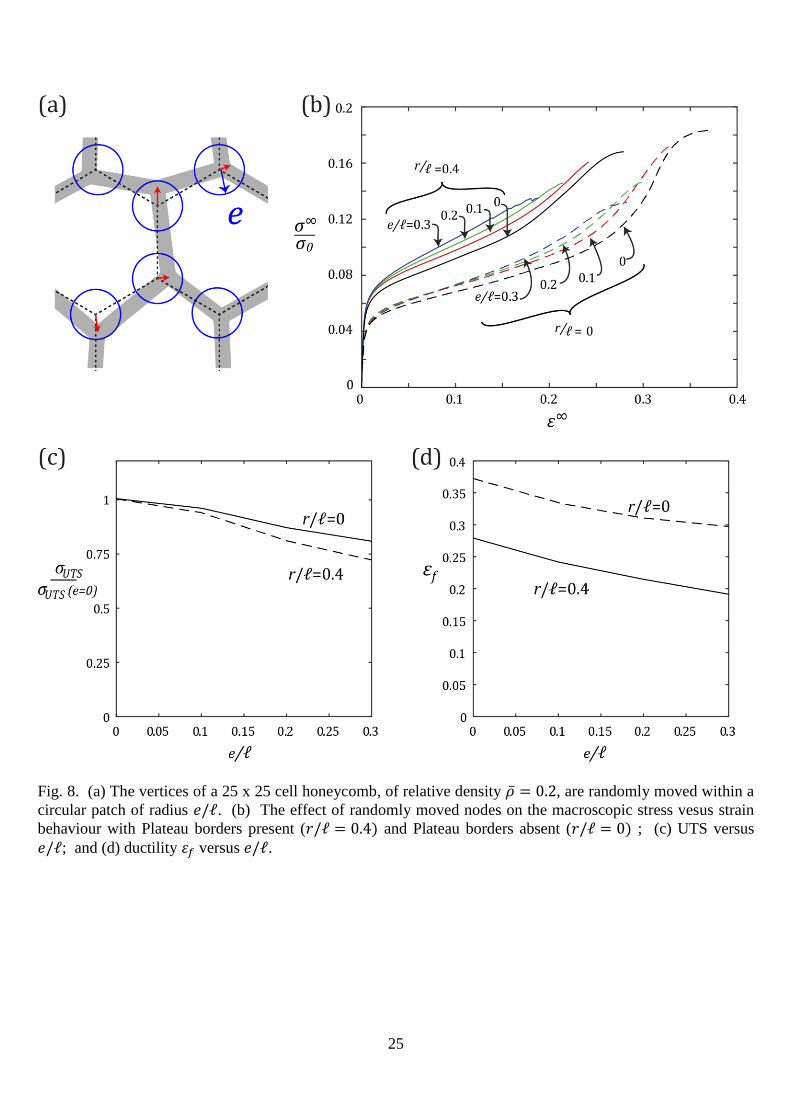
5.1 RANDOM POSITIONING OF NODES
In order to investigate the effect of cell wall misalignment, a large RVE is considered
containing 25x25 cells. The nodes of this honeycomb (defined as the points of intersection of the
mid-axis of the 3 beams that form a joint) are disturbed in position within a circular disc of radius e,
with equal probability of displacement to any point within the circular disc, as shown in Fig. 8a.
The random movement of nodes has a small effect on the uniaxial response regardless of whether
Plateau borders are present or absent, see Fig. 8b. There is a small increase in elastic modulus (not
shown here), in yield strength and in strain hardening rate with increasing misalignment, in
agreement with the findings of Chen et al.(1999). In contrast, cell wall misalignments cause a small
11
reduction in both ultimate tensile strength and macroscopic ductility, as summarised in Figs. 8c and
d, respectively. We note in passing that the geometry for Plateau borders present (𝑟/ℓ = 0.4) and
�̅� = 0.2 has already been sketched in Fig. 2c.
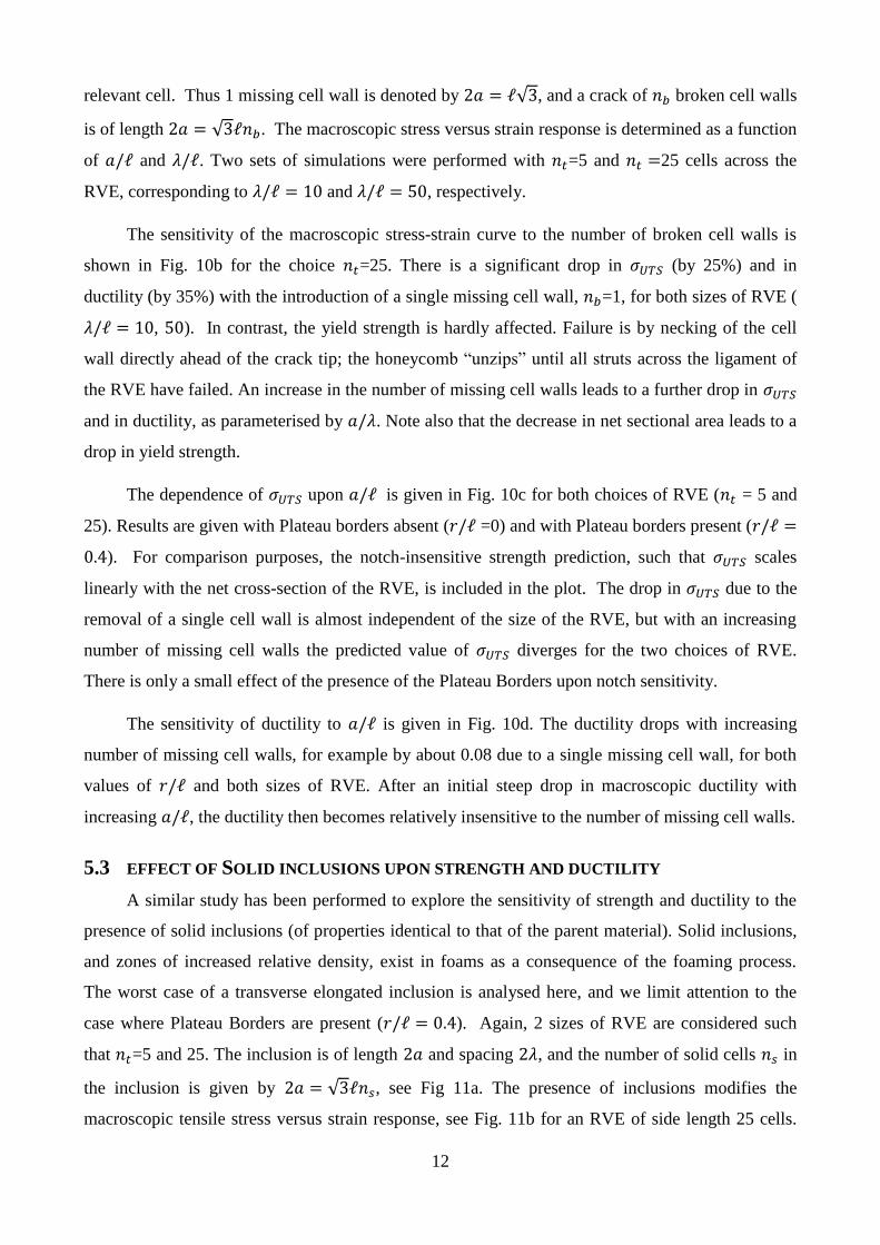
In order to gain additional insight into the effect of random movement of nodes upon the
deformation and failure response, the deformed mesh of the misaligned honeycomb (𝑒/ℓ=0.3; no
Plateau Borders) was examined at selected stages of applied macroscopic strain. Individual strut
failure is deemed to have occurred when the cross-section of the strut thins by more than 20%. The
sequence of strut failures is shown in Fig. 9. Recall that Consider necking begins at a true stain of
0.1 in uniformly strained strut (without bending). In the post-processing of results to illustrate the
progression of failed bars, it was necessary to adopt an arbitrary criterion for a necked strut. The
load-carrying capacity is negligible when the thickness has reduced by 20%. A different choice has
negligible impact on the failure sequence shown in Fig. 9.
Isolated strut failures occur prior to reaching the remote peak strength. In general, these struts
are shorter than the average value and are mostly parallel to the loading direction: these struts
transition in response from plastic bending to plastic stretching at lower remote strains. The
progressive nature of failure of the honeycomb is explored by grouping the failure of individual
struts into 4 regimes depending upon the macroscopic strain level at which each strut fails, see Fig.
9. The initial failures are isolated and uncorrelated: nearest neighbours do not necessarily fail next.
However, as the macroscopic strain is increased, a plane of failed necks emerges perpendicular to
the macroscopic loading direction. The plane of failed necks resembles a macroscopic crack and the
high stress concentration at the crack tip leads to failure in the honeycomb at the crack tip. We note
in passing that the failure plane is normal to the loading direction, consistent with the observations
of the macroscopic fracture surface for metallic foams by Ochiai et al. (2010a, b).
5.2 MISSING CELL WALLS
The sensitivity of strength and ductility of a regular honeycomb to missing cell walls is now
explored. Missing cell walls are also representative of cell walls that have been significantly
weakened due to grain boundary embrittlement, for example. Note that an array of missing cell
walls generates a crack-like irregular cell, and the sensitivity of macroscopic ductility to a cluster of
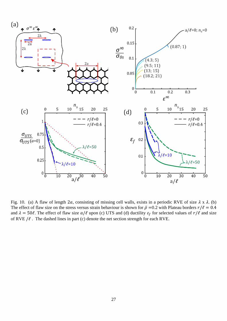
missing cell walls is now explored. A square RVE of side length 2𝜆, containing a single central
crack of length 2𝑎, is subjected to periodic boundary conditions, as shown in Fig. 10a. The side
length of the square RVE has 𝑛𝑡 cells such that 𝜆/ℓ ≈ 2𝑛𝑡.
There is choice in the definition of the crack tip location within the hexagonal cell: in our
definition of a we shall make the arbitrary choice of placing the crack tip at the centre of the
12
relevant cell. Thus 1 missing cell wall is denoted by 2𝑎 = ℓ√3, and a crack of 𝑛𝑏 broken cell walls
is of length 2𝑎 = √3ℓ𝑛𝑏. The macroscopic stress versus strain response is determined as a function
of 𝑎/ℓ and 𝜆/ℓ. Two sets of simulations were performed with 𝑛𝑡=5 and 𝑛𝑡 =25 cells across the
RVE, corresponding to 𝜆/ℓ = 10 and 𝜆/ℓ = 50, respectively.
The sensitivity of the macroscopic stress-strain curve to the number of broken cell walls is
shown in Fig. 10b for the choice 𝑛𝑡=25. There is a significant drop in 𝜎𝑈𝑇𝑆 (by 25%) and in
ductility (by 35%) with the introduction of a single missing cell wall, 𝑛𝑏=1, for both sizes of RVE (
𝜆/ℓ = 10, 50). In contrast, the yield strength is hardly affected. Failure is by necking of the cell
wall directly ahead of the crack tip; the honeycomb “unzips” until all struts across the ligament of
the RVE have failed. An increase in the number of missing cell walls leads to a further drop in 𝜎𝑈𝑇𝑆
and in ductility, as parameterised by 𝑎/𝜆. Note also that the decrease in net sectional area leads to a
drop in yield strength.
The dependence of 𝜎𝑈𝑇𝑆 upon 𝑎/ℓ is given in Fig. 10c for both choices of RVE (𝑛𝑡 = 5 and
25). Results are given with Plateau borders absent (𝑟/ℓ =0) and with Plateau borders present (𝑟/ℓ =
0.4). For comparison purposes, the notch-insensitive strength prediction, such that 𝜎𝑈𝑇𝑆 scales
linearly with the net cross-section of the RVE, is included in the plot. The drop in 𝜎𝑈𝑇𝑆 due to the
removal of a single cell wall is almost independent of the size of the RVE, but with an increasing
number of missing cell walls the predicted value of 𝜎𝑈𝑇𝑆 diverges for the two choices of RVE.
There is only a small effect of the presence of the Plateau Borders upon notch sensitivity.
The sensitivity of ductility to 𝑎/ℓ is given in Fig. 10d. The ductility drops with increasing
number of missing cell walls, for example by about 0.08 due to a single missing cell wall, for both
values of 𝑟/ℓ and both sizes of RVE. After an initial steep drop in macroscopic ductility with
increasing 𝑎/ℓ, the ductility then becomes relatively insensitive to the number of missing cell walls.
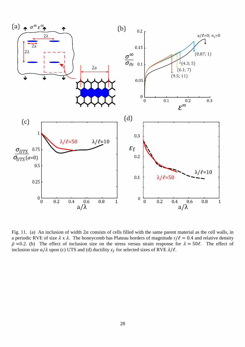
5.3 EFFECT OF SOLID INCLUSIONS UPON STRENGTH AND DUCTILITY
A similar study has been performed to explore the sensitivity of strength and ductility to the
presence of solid inclusions (of properties identical to that of the parent material). Solid inclusions,
and zones of increased relative density, exist in foams as a consequence of the foaming process.
The worst case of a transverse elongated inclusion is analysed here, and we limit attention to the
case where Plateau Borders are present (𝑟/ℓ = 0.4). Again, 2 sizes of RVE are considered such
that 𝑛𝑡=5 and 25. The inclusion is of length 2𝑎 and spacing 2𝜆, and the number of solid cells 𝑛𝑠 in
the inclusion is given by 2𝑎 = √3ℓ𝑛𝑠, see Fig 11a. The presence of inclusions modifies the
macroscopic tensile stress versus strain response, see Fig. 11b for an RVE of side length 25 cells.

13
There is a moderate drop in 𝜎𝑈𝑇𝑆 and in ductility with increasing size of inclusion: upon in-filling a
single cell with parent material, 𝜎𝑈𝑇𝑆 drops by 5% and the ductility drops by 10%. The
corresponding drops are somewhat greater for a missing cell wall, recall Fig. 10a. The sensitivity of
𝜎𝑈𝑇𝑆 and ductility to the presence of an inclusion is plotted as a function of 𝑎/𝜆 in Figs. 11c and d,
respectively, for both sizes of RVE. It is clear that the parameter 𝑎/𝜆 dictates the magnitude of
𝜎𝑈𝑇𝑆 and ductility (in contrast to the parameter 𝑎/ℓ for missing cell walls, recall Fig. 10c, d).
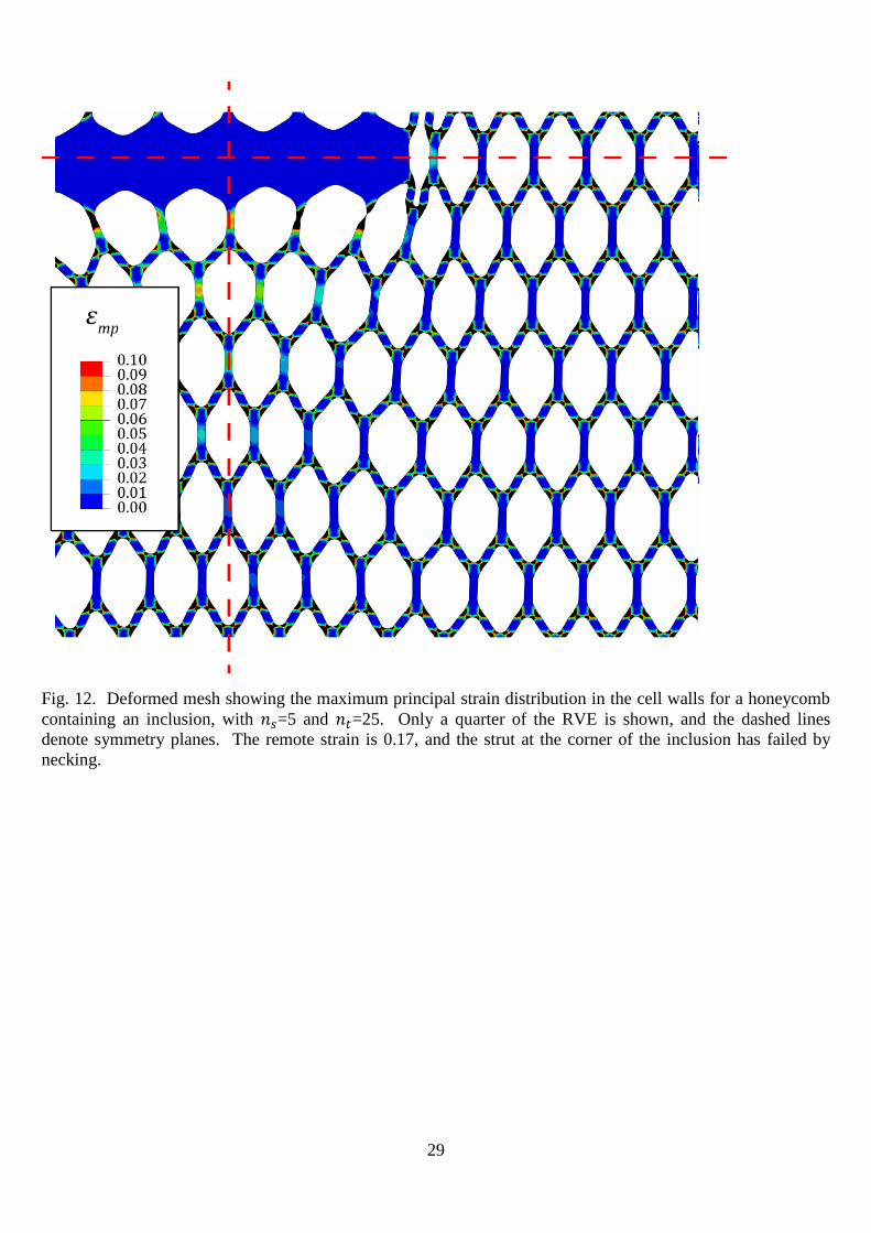
Our physical interpretation of the knockdown in strength and ductility due to the presence of an
inclusion is as follows. The elongated inclusion induces a bi-axial stress state adjacent to the top
and bottom faces of the inclusion by restricting the lateral contraction of the neighbouring
honeycomb. A strain concentration exists at the end of the inclusion, and is associated with the
transition from a state of uniaxial strain along the upper and lower sides of the inclusion to a state of
uniaxial stress remote from the inclusion. The state of biaxial stressing adjacent to the inclusion is
evident from the deformed configuration in Fig. 12, for 𝑛𝑡=25 and 𝑛𝑠=5 and for a macroscopic
strain of 0.17. This state of deformation in Fig. 12 is shown just after peak stress has been attained.
Failure occurs by necking of the strut at the corner of the array of inclusions. In the following
section, the knockdown in ductility due to a biaxial stress state is explored in order to illustrate its
potency.
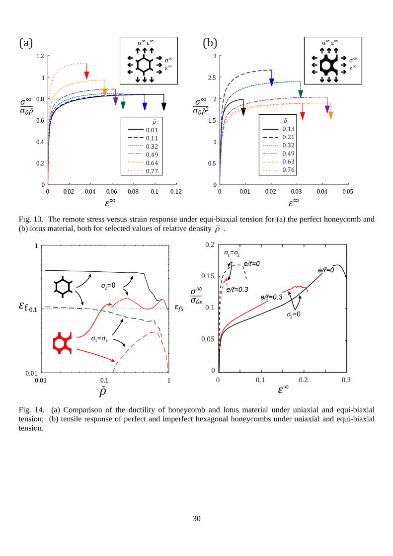
6 EQUI-BIAXIAL TENSION
We proceed to investigate the macroscopic ductility of regular honeycomb and lotus material
under equi-biaxial tension in order to gain further insight into the reduction in ductility due to the
presence of an inclusion. A hydrostatic stress state also exists in foam manufacture by solid-state
foaming, and the degree of foaming that can be achieved is limited by necking of the cell walls.
The simulation procedure is the same as that for uniaxial loading, as described in Section 4,
except that equal macroscopic straining is now applied in the 𝑋1 and 𝑋2 directions. The stress
versus strain response is presented for both the hexagonal honeycomb and lotus materials in Fig. 13
(equi-biaxial straining resulted in an equi-biaxial stress state over the entire strain range investigated
here). Macroscopic equi-biaxial tension generates negligible bending of the cell walls, and
deformation occurs via stretching of the cell walls, see for example Gibson and Ashby (1999).
Consequently, the macroscopic tensile stress versus strain response of the lattice has a similar shape
to that of the parent solid, and has a comparable ductility.
Tensile failure in both uniaxial tension and equi-biaxial tension is dominated by plastic
stretching and necking of the struts. Consequently, for both uniaxial and equi-biaxial tension, the
14
ultimate tensile strength of the honeycomb material scales with �̅� and that of the lotus material
scales with �̅�2 (recall that the slenderness ratio for the cell walls of the lotus material scales as �̅�−2).
It is clear from Fig. 14a that the macroscopic ductility under equi-biaxial loading is significantly
less than that for uniaxial tension: under uniaxial loading, the cell walls first bend and then stretch,
whereas for biaxial loading the cell walls only stretch.
The stress versus strain responses of the perfect hexagonal honeycomb, and the hexagonal
honeycomb with randomly moved nodes (𝑒/ ℓ=0.3), are shown in Fig 14b for both uniaxial tension
and equi-biaxial tension. For both topologies, the yield strength and degree of strain hardening are
higher for equi-biaxial tension than for uniaxial tension. The ductility of the perfect lattice is
reduced from 0.28 for uniaxial tension to 0.05 for equi-biaxial loading (a knockdown of 80%), and
the ductility of the imperfect lattice is reduced from 0.18 for uniaxial tension to 0.02 for equi-biaxial
loading (a knockdown of 90%). We conclude that the ductility is significantly reduced either by
randomly moving the nodes of the cell wall or by the introduction of equi-biaxial stress.
7 DISCUSSION
7.1 RELATION BETWEEN MICROSTRUCTURE AND PROPERTIES
It is remarkable that the predicted macroscopic ductility of the ideal hexagonal honeycomb is
approximately 40% (for 𝑁=0.1 and �̅�<40%) whereas the observed ductility of most structural foams
is below 10%. In an attempt to explain this discrepancy, the effect of commonly observed defects of
foam topology upon ductility has been explored in this study. It is found that Plateau borders and
randomly moved nodes have a mild effect on the ductility. In contrast, missing cell walls and
inclusions (cells filled with the parent solid) dramatically reduce the ductility; for example, a single
missing cell wall (in an RVE of 25x25 cells) reduces the ductility by one third.
Mangipudi and Onck (2011) reported a similar relative drop in 𝜎𝑈𝑇𝑆 for random honeycombs
(Voronoi) compared to perfect hexagonal honeycombs. Likewise, they observed a similar relative
drop in macroscopic ductility when a periodic microstructure is replaced by a random one.
The severe knockdown in ductility observed in the present study upon introducing 1 or 2
missing cell walls is consistent with a transition flaw size of ~1.8ℓ as reported by Fleck and Qiu
(2007). Additional studies have noted the potency of missing cell walls upon the mechanical
properties of cellular solids: Gan et al. (2005) found that 2% missing walls reduce the modulus by
15% and Chen et al (1999) reported a 50% loss of yield strength upon introducing 5% missing cell
walls. Similar reductions in yield strength with missing cell walls have been observed by Wang and
McDowell (2003).
15
7.2 FAILURE OF ELASTIC-PLASTIC CELLULAR SOLIDS
The present study assumes that the tensile failure of cellular solids is by necking of cell walls.
This failure mechanism is supported by observations reported in the literature: San Marchi et al.
(2004) examined the fracture surface of pure Al open-cell foams and report necking of cell walls.
Likewise, Ochiai et al. (2010a, b) observed that nickel and copper foams fail by cell-wall necking,
with the fracture surface confined to a planar section approximately one cell in height and normal to
the loading direction.
In contrast to the ductile failure (necking) mechanism considered herein, the failure mechanism
assumed by Onck and colleagues comprises damage initiation and growth, based on the
achievement of a critical value of local strain across the cell wall. At the macroscopic level,
deformation localises in a shear band with unit normal 30° to 60° to the loading direction. While the
approach of Onck and colleagues is pertinent to modelling the embrittlement of cell walls (for
example by segregation of a brittle phase to grain boundaries), the observation of failure surfaces
normal to the loading direction and the presence of necked struts suggest that the present approach
is more appropriate for modelling the failure of a ductile cellular solid.
8 CONCLUDING REMARKS
The hexagonal honeycomb is a useful 2D prototype for a 3D foam: both are bending-
dominated structures, with mechanical properties that are sensitive to the slenderness ratio of the
struts. The present study sheds light on possible reasons for the low observed values of tensile
ductility of foams. Low ductility may be due to the embrittlement of grain boundaries during
processing, as highlighted by Onck and co-workers (Amsterdam et al., 2005; Onck et al., 2004;
Onck et al., 2005), it may be due to geometric imperfections within the honeycomb, or both. Onck
and co-workers (Mangipudi and Onck, 2011, 2012) reveal that the brittle decohesion of cell walls
gives fracture planes that are inclined to the loading direction; in contrast, necking failures give
failure planes that reside normal to the loading direction. The present study has considered a
number of possible geometric sources of the knockdown in ductility of a foam, with the most potent
due to missing cell walls. The degree of reduction in ductility has been quantified, and the rather
minor role played by material strain hardening has been emphasised. Our study also reveals that
large inclusions within the honeycomb induce a local strain concentration and thereby further
degrade the ductility.

16
9 ACKNOWLEDGEMENTS
The authors are grateful for financial support from SABIC, and for numerous technical
discussions with Dr. Martin van Es. They are also grateful for funding in the form of an ERC
advanced grant 669764, MULTILAT, and to the US Office of Naval Research N62909-14-1-N232,
project manager Dr. David Shifler.
17
10 REFERENCES
Amsterdam, E., De Vries, J., De Hosson, J.T.M., Onck, P., 2008. The influence of strain-induced damage on
the mechanical response of open-cell aluminum foam. Acta Materialia 56, 609-618.
Amsterdam, E., Onck, P., De Hosson, J.T.M., 2005. Fracture and microstructure of open cell aluminum
foam. Journal of materials science 40, 5813-5819.
Andrews, E., Sanders, W., Gibson, L.J., 1999. Compressive and tensile behaviour of aluminum foams.
Materials Science and Engineering: A 270, 113-124.
Chen, C., Lu, T., Fleck, N.A., 1999. Effect of imperfections on the yielding of two-dimensional foams.
Journal of the Mechanics and Physics of Solids 47, 2235-2272.
Deshpande, V.S., Ashby, M.F., Fleck, N.A., 2001. Foam topology: bending versus stretching dominated
architectures. Acta Materialia 49, 1035-1040.
Deshpande, V.S., Fleck, N.A., 2001. Multi-axial yield behaviour of polymer foams. Acta Materialia 49,
1859-1866.
Fleck, N.A., Deshpande, V.S., Ashby, M.F., 2010. Micro-architectured materials: Past, present and future.
Proceedings of the Royal Society A: Mathematical, Physical and Engineering Sciences 466, 2495-2516.
Fleck, N.A., Qiu, X., 2007. The damage tolerance of elastic–brittle, two-dimensional isotropic lattices.
Journal of the Mechanics and Physics of Solids 55, 562-588.
Fleck, N.A., Zisis, T., 2010. The erosion of EB-PVD thermal barrier coatings: The competition between
mechanisms. Wear 268, 1214-1224.
Gan, Y., Chen, C., Shen, Y., 2005. Three-dimensional modeling of the mechanical property of linearly
elastic open cell foams. International Journal of Solids and Structures 42, 6628-6642.
Gibson, L.J., Ashby, M.F., 1999. Cellular Solids: Structure and Properties. Cambridge University Press.
Gong, L., Kyriakides, S., 2005. Compressive response of open cell foams Part II: Initiation and evolution of
crushing. International Journal of Solids and Structures 42, 1381-1399.
Gong, L., Kyriakides, S., Triantafyllidis, N., 2005. On the stability of Kelvin cell foams under compressive
loads. Journal of the Mechanics and Physics of Solids 53, 771-794.
Goodall, R., Mortensen, A., 2014. Porous Metals, in: Hono, K., Laughlin, D. (Eds.), Physical Metallurgy: 5th
Edition. Elsevier, Amsterdam, NL.
Jang, W.-Y., Kyriakides, S., 2009. On the crushing of aluminum open-cell foams: Part II analysis.
International Journal of Solids and Structures 46, 635-650.
Jang, W.-Y., Kyriakides, S., Kraynik, A.M., 2010. On the compressive strength of open-cell metal foams
with Kelvin and random cell structures. International Journal of Solids and Structures 47, 2872-2883.
Mangipudi, K., Onck, P., 2011. Multiscale modelling of damage and failure in two-dimensional metallic
foams. Journal of the Mechanics and Physics of Solids 59, 1437-1461.
Mangipudi, K., Onck, P., 2012. Tensile failure of two-dimensional quasi-brittle foams. International Journal
of Solids and Structures 49, 2823-2829.
Nakajima, H., 2007. Fabrication, properties and application of porous metals with directional pores. Progress
in Materials Science 52, 1091-1173.
18
Ochiai, S., Nakano, S., Fukazawa, Y., Aly, M.S., Okuda, H., Kato, K., Isobe, T., Kita, K., Honma, K., 2010a.
Change of Young's Modulus with Increasing Applied Tensile Strain in Open Cell Nickel and Copper Foams.
Materials transactions 51, 925-932.
Ochiai, S., Nakano, S., Fukazawa, Y., Aly, M.S., Okuda, H., Kato, K., Isobe, T., Kita, K., Honma, K., 2010b.
Tensile deformation and failure behavior of open cell nickel and copper foams. Materials transactions 51,
699-706.
Onck, P., Van Merkerk, R., De Hosson, J.T.M., Schmidt, I., 2004. Fracture of metal foams: in-situ testing
and numerical modeling. Advanced Engineering Materials 6, 429-431.
Onck, P., Van Merkerk, R., Raaijmakers, A., De Hosson, J.T.M., 2005. Fracture of open-and closed-cell
metal foams. Journal of materials science 40, 5821-5828.
Papka, S.D., Kyriakides, S., 1994. In-plane compressive response and crushing of honeycomb. Journal of the
Mechanics and Physics of Solids 42, 1499-1532.
Papka, S.D., Kyriakides, S., 1998. Experiments and full-scale numerical simulations of in-plane crushing of
a honeycomb. Acta Materialia 46, 2765-2776.
Romijn, N.E., Fleck, N.A., 2007. The fracture toughness of planar lattices: imperfection sensitivity. Journal
of the Mechanics and Physics of Solids 55, 2538-2564.
San Marchi, C., Despois, J.-F., Mortensen, A., 2004. Uniaxial deformation of open-cell aluminum foam: the
role of internal damage. Acta Materialia 52, 2895-2902.
Simone, A.E., Gibson, L.J., 1998. Effects of solid distribution on the stiffness and strength of metallic foams.
Acta Materialia 46, 2139-2150.
Song, Y., Wang, Z., Zhao, L., Luo, J., 2010. Dynamic crushing behavior of 3D closed-cell foams based on
Voronoi random model. Materials & design 31, 4281-4289.
Tankasala, H.T., Deshpande, V.S., Fleck, N.A., in prep. Tensile response and damage tolerance of
elastoplastic lattices.
Triantafyllidis, N., Schraad, M., 1998. Onset of failure in aluminum honeycombs under general in-plane
loading. Journal of the Mechanics and Physics of Solids 46, 1089-1124.
Wang, A.-J., McDowell, D.L., 2003. Effects of defects on in-plane properties of periodic metal honeycombs.
International Journal of Mechanical Sciences 45, 1799-1813.
Weaire, D.L., Hutzler, S., 2001. The physics of foams. Oxford University Press.
Zhou, J., Mercer, C., Soboyejo, W., 2002. An investigation of the microstructure and strength of open-cell
6101 aluminum foams. Metallurgical and Materials Transactions A 33, 1413-1427.
Zhu, H., Hobdell, J., Windle, A., 2001. Effects of cell irregularity on the elastic properties of 2D Voronoi
honeycombs. Journal of the Mechanics and Physics of Solids 49, 857-870.
19
FIGURES
Fig. 1. Nominal tensile failure strain of open-cell metallic and polymeric foams as a function of relative density
.
Fig. 2. Unit cell of (a) regular hexagonal honeycomb; (b) lotus material; and (c) hexagonal honeycomb with
Plateau borders of radius 𝑟=0.4 (and relative density 0.2 ).
20
Fig. 3. Non-dimensional nominal tensile stress versus nominal strain response of (a) regular hexagonal
honeycomb, N=0.1; (b) lotus material, N=0.1; (c) regular hexagonal honeycomb, N=0.33; and (d) lotus material,
N=0.33.
21
Fig. 4. Nominal stress versus nominal strain response of lotus material (�̅�=0.56) and of hexagonal honeycomb
(�̅�=0.11 and 0.49). Inserts show contours of maximum principal strain 𝜀𝑚𝑝 within the cell wall in the deformed
configuration at selected values of macroscopic strain.
22
Fig. 5. The dependence of yield strength 𝜎𝑦, ultimate tensile strength 𝜎𝑈𝑇𝑆, ductility 𝜀𝑓 , and energy absorption
𝑊𝑓 upon relative density �̅� for a regular hexagonal honeycomb and lotus material. (a) 𝜎𝑦 and 𝜎𝑈𝑇𝑆 versus �̅� for
𝑁=0.1; (b) 𝜎𝑈𝑇𝑆 versus �̅� for 𝑁=0.1 and 𝑁=0.33; (c) 𝜀𝑓 versus �̅� for 𝑁=0.1 and 𝑁=0.33; and (d) 𝑊𝑓 versus �̅�
for 𝑁=0.1 and 𝑁=0.33.
23
Fig. 6. Contours of normalised axial stress in a vertical strut of the regular honeycomb as a function of
applied strain and relative density . The stress is the average value across section A-A of the cell wall
as shown in the insert, and is normalised by the yield strength of the solid 0s .
24
Fig. 7. Sensitivity of macroscopic nominal stress versus nominal strain response to the presence of Plateau
borders in a regular hexagonal honeycomb for (a) �̅� = 0.06 and (b) �̅� = 0.49. The effect of Plateau border size
𝑟/ℓ on (c) 𝜎𝑈𝑇𝑆 and (d) ductility 𝜀𝑓 for selected values of relative density �̅�.
25
Fig. 8. (a) The vertices of a 25 x 25 cell honeycomb, of relative density �̅� = 0.2, are randomly moved within a
circular patch of radius 𝑒/ℓ. (b) The effect of randomly moved nodes on the macroscopic stress vesus strain
behaviour with Plateau borders present (𝑟/ℓ = 0.4) and Plateau borders absent (𝑟/ℓ = 0) ; (c) UTS versus
𝑒/ℓ; and (d) ductility 𝜀𝑓 versus 𝑒/ℓ.

26
Fig. 9. The failure of individual struts in an RVE of 25 x 25 cells is shown on the undeformed configuration.
The 4 symbols indicate the regime of macroscopic strain over which the struts fail by necking. Note that struts
marked by X have failed post peak macroscopic stress.
27
Fig. 10. (a) A flaw of length 2𝑎, consisting of missing cell walls, exists in a periodic RVE of size 𝜆 x 𝜆. (b)
The effect of flaw size on the stress versus strain behaviour is shown for �̅� =0.2 with Plateau borders 𝑟/ℓ = 0.4
and 𝜆 = 50ℓ. The effect of flaw size 𝑎/ℓ upon (c) UTS and (d) ductility 𝜀𝑓 for selected values of 𝑟/ℓ and size
of RVE /ℓ . The dashed lines in part (c) denote the net section strength for each RVE.
28
Fig. 11. (a) An inclusion of width 2𝑎 consists of cells filled with the same parent material as the cell walls, in
a periodic RVE of size 𝜆 x 𝜆. The honeycomb has Plateau borders of magnitude r/ℓ = 0.4 and relative density
�̅� =0.2. (b) The effect of inclusion size on the stress versus strain response for 𝜆 = 50ℓ. The effect of
inclusion size 𝑎/𝜆 upon (c) UTS and (d) ductility 𝜀𝑓 for selected sizes of RVE 𝜆/ℓ.
29
Fig. 12. Deformed mesh showing the maximum principal strain distribution in the cell walls for a honeycomb
containing an inclusion, with 𝑛𝑠=5 and 𝑛𝑡=25. Only a quarter of the RVE is shown, and the dashed lines
denote symmetry planes. The remote strain is 0.17, and the strut at the corner of the inclusion has failed by
necking.
30
Fig. 13. The remote stress versus strain response under equi-biaxial tension for (a) the perfect honeycomb and
(b) lotus material, both for selected values of relative density .
Fig. 14. (a) Comparison of the ductility of honeycomb and lotus material under uniaxial and equi-biaxial
tension; (b) tensile response of perfect and imperfect hexagonal honeycombs under uniaxial and equi-biaxial
tension.