Embed Size (px)
Citation preview
A direct comparison of the incoherent intensity <luI2> determined by formula (15) with [4] is impossible because of the absence of an explicit expression for <lu12> in [4]. How- ever, the physical meaning of <lu12> and of the incoherent scattering cross section in the spectral form (182) of [4] is comparable: both quantities are determined by the correspond- ing attenuation factors along the incident and scattered paths which depend on their direc- tions. The advantage of the coordinate representation (15) lies in the expression in terms of a generalization of sufficiently simple asymptotic expressions of L. M. Brekhovskikh to the case when Ne(k i) depends on the direction of h~. In addition, higher iterations in the solution of the dynamical problem (8) can find application, for example, in the calculation of the higher-order spectra under glancing propagation.
LITERATURE CITED
i. F. G. Bass and I. M. Fuks, Scattering of Waves from a Statistically Uneven Surface [in Russian], Nauka, Moscow (1972).
2. V. D. Freilikher and I. M. Fuks, Izv. Vyssh. Uchebn. Zaved., Radiofiz., 13, 73 (1970). 3. N. P. Zhuk and O. A. Tret'yakov, Preprint IRE AN UkrSSR No. 174, Kharkov (1981). 4. K. Furutsu and D. Eng, IRE Proc., F 130, 601 (1983). 5. S. Ito, Radio Sci., 20, I (1985). 6. A. S. Bryukhovetskii, Proc. 9th All-Union Symposium on the Diffraction and Propagation
of Waves [in Russian], Vol. I, Tbilisi (1985), p. 203. 7. V. N. Alekseev and V. M. Komissarov, Trudy Akust. Inst., No. 4, 27 (1968). 8. L. A. Apresyan, Izv. Vyssh. Uchebn. Zaved., Radiofiz., 17, 165 (1974). 9. S. M. Rytov, Yu. A. Kravtsov and V. I, Tatarskii, Introduction to Statistical Radio-
physics. Part 2: Random Fields [in Russian], Nauka, Moscow (1978). i0. V. D. Freilikher and I. M. Fuks, Izv. Vyssh. Uchebn. Zaved., Radiofiz., 19, 401 (1976). ii. A. S. Bryukhovetskii and I. M. Fuks, Izv. Vyssh. Uchebn. Zaved., Radiofiz., 28, 1400
(1985). 12. L. M. Brekhovskikh, Waves in Layered Media, Academic Press (1970).
EXPERIMENTAL STUDY OF A SYSTEM FOR AUTOMATIC CONTROL
OF THE BOUNDARY CONDITIONS IN A WAVEGUIDE WITH AN
ADAPTIVE TUNING ALGORITHM
A. N. Malakhov, A. A. Mal'tsev, S. Yu. Medvedev, and V. V. Cherepennikov
UDC 534.832:534.2-16
The reflection of an underwater sound wave from an active boundary is investi- gated. Relations for the phases and amplitudes of the boundary vibrations and the incident wave are given for the attainment of a prescribed reflection co- efficient. A block diagram, procedure, and results are given for experiments on active control of the boundary conditions in a waveguide. Control is achieved by the programmed implementation of an adaptive search algorithm for real-time minimization of the standard deviation. An adaptively controlled preionization electroacoustic generator is used to obtain a matched load against the background of a boundary with a time-varying reflection coefficient.
It is a well-known fact that the testing and calibration of underwater acoustical equip- ment under the conditions of a free wave field offers the most complete and accurate results [i]. On the other hand, the creation of such conditions in the presence of reflections from the walls of the laboratory tank does not pose a simple problem. Its solution requires im-
N. I. Lobachevskii State University, Gorki. Translated from Izvestiya Vysshikh Ucheb- nykh Zavedenii, Radiofizika, Vol. 31, No. 3, pp. 327-333, March, 1988. Original article sub- mitted June 4, 1986.
0033-8443/88/3103-0241512.50 �9 1988 Plenum Publishing Corporation 241
pedance matching between the tank walls and the liquid [2]. Matching can be achieved either by the application of absorbing coatings or by means of systems for the active sup- pression of reflected waves [3-6]. Here we give the results of experiments on the use of an active suppression system with an adaptive search algorithm for the creation of wave fields having a specified structure in a laboratory facility.
We first consider reflection from an active boundary. We assume for simplicity that a plane wave Pp(x, t) = P exp[i(kx + mr)] is normally incident on the plane x = 0 of a P boundary with a passive reflection coefficient K a exp (i~ n) . The wave PR = KnPp exp [i(-kx + ~t + ~n)] propagates away from the boundary as a result of passive reflection. In the active regime, the boundary excites the wave Pa exp [i(-kx +mt + ~a)] in the absence of an incident wave. Accordingly, under the action of the wave Pp(x, t) the wave PR* = [KnPp exp (i~n) + exp (i~n) +Pa exp (i~a) ] exp [i(-nkx+ ~t) ] is "reflected" from the boundary. We assume that the passive reflection coefficient remains the same in the active regime, in which case we can write the modulus and phase of the coefficient of reflection from the active boundary in the form [2]
(i) ? ----- atctg Rnsin~n+~sin~a , ~== Pa
R,, ,cos ~p,, + =,cos ~ Pp Specifying the values of R and ~, we can determine the values of ~ and ~ for known values of R n and ~pn in order to create a boundary having the required reflection coefficient:
~= (R 2 --~R.,eos,(cp -- q~,,) +R'.)~/2,
%---- arctg R sin q~ -- R,, sin @, R ,cOs q) ~ R~ ,cOS q~.
(2)
The experiments were carried out in a water-filled Duralumin tank having a length L = 2.2 m, an outside diameter D = 50 mm, and a wall thickness d = 6 mm. The parameters of the incident and reflected waves in the measurement tube were constrained by virtue of reflec- tion at both ends. The fundamental difficulties of achieving specified values of R and are not encountered here. However, the selection of a reference signal for the active system is complicated by strong wave feedback for large values of the passive reflection coeffi- cients at the ends [7, 8]. If it is difficult to place the radiator on the boundary itself for some reason or other, the required reflection coefficient can be obtained by placing a unidirectional preionization electroacoustic (PIE) generator in the inmlediate vicinity of the boundary, where it generated the wave P~ exp[i(-kx + ~t + ~a)] [9].
The necessary boundary conditions are easily established, once ~ and ~ have been cal- culated according to Eq. (2) and specified exactly for known constant parameters of the lab- oratory facility, viz.: the passive reflection coefficients of the tank walls and the place- ment geometry of the sensors and radiators of the active suppression system. However, if the parameters are not specified completely or if they are liable to vary in the course of the experiment, the indicated procedure for adjustment of the control system cannot be used. Adaptive systems for the control of active reflection must be used in this case [i0]. Appara- tus, procedure, and results of experiments on the application of such a system are set forth below.
Figure 1 shows the placement of the elements and the experimental arrangement. The measurement control system includes instrumental digital signal processors, an Elektronika KI-20 microcomputer, adjustable delay lines, sine-wave and timing-pulse generators, ampli- fiers for the measurement hydrophones, amplifiers for excitation of the piezoelectric cer- amic radiating transducers and the PIE generators, and recording equipment.
Hardware digital processing of the signals from the measurement hydrophones yielded signals corresponding to the incident (propagating from right to left) wave Pp(t) and the
reflected wave PR*(t) [ii]. The excitation signals driving the suppressing radiators were
also hardware-generated.
242
II li!i l!:l / - ~ . / \ /
C L
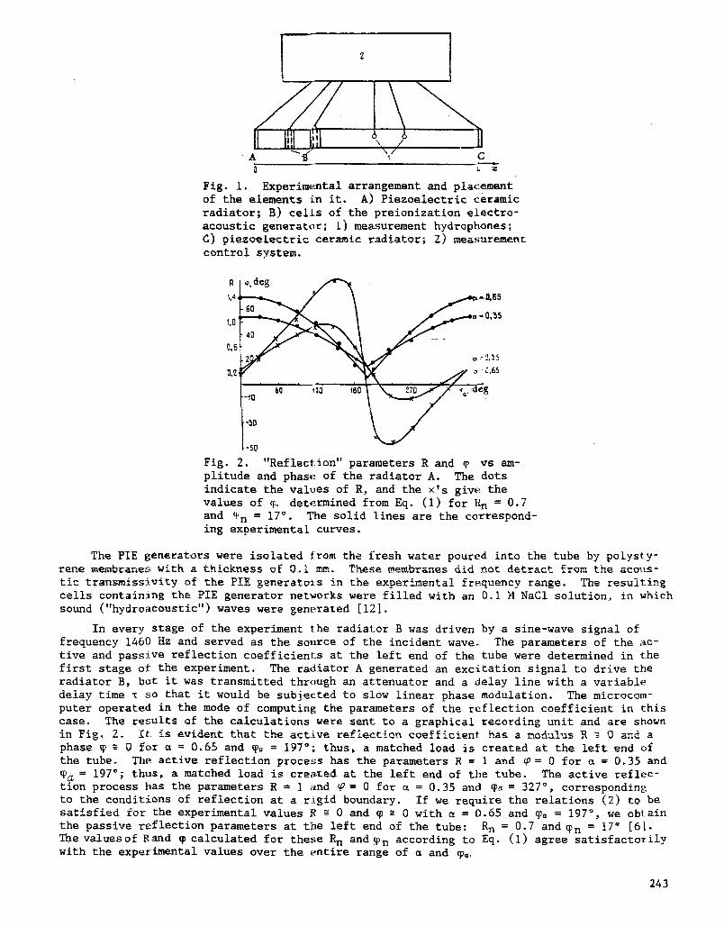
Fig. i. Experimental arrangement and placement of the elements in it. A) Piezoelectric ceramic radiator; B) cells of the preionization electro- acoustic generator; i) measurement hydrophones; d) piezoelectric ceramic radiator; Z) measurement control system.
1,4,
1,0' c , - 0,'~5
.-50
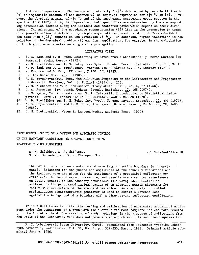
Fig. 2. "Reflection" parameters R and ~ vs am- plitude and phase of the radiator A. The dots indicate the values of R, and the x's give the values of % determined from Eq. (I) for R n = 0.7 and ~n = 17~ The solid lines are the correspond- ing experimental curves.
The PIE generators were isolated from the fresh water poured into the tube by polysty- rene membranes with a thickness of 0.1 mm. These membranes did not detract from the acous- tic transmissivit~ of the PIE generators in the experimental frequency range. The resulting cells containin~ the PIE generator networks were filled with an 0,i M NaCI solution, in which sound ("hydroacoustic") waves were generated [12].
In every stage of the experiment the radiator B was driven by a sine-wave signal of frequency 1460 Hz and served as the source of the incident wave. The parameters of the ac- tive and passive reflection coefficients at the left end of the tube were determined in the first stage of the experiment. The radiator A generated an excitation signal to drive the radiator B, but it was transmitted through an attenuator and a deiay line with a variable delay time ~ so that it would be subjected to slow linear phase modulation. The microcom- puter operated in the mode of computing the parameters of the reflection coefficient in this case. The results of the calculations were sent to a graphical recording unit and are shown in Fi B . 2. It is evident that the active refiectien coefficient has a modulus R ~ 0 and a phase ~ ~ O for m = 0.65 and ~= = 197~ thus, a matched load is created at the left end of the tube. The active reflection process has the parameters R = ] and ~ = 0 for ~ = 0.35 and ~ = 197~ thus, a matched load is created at the left end of the tube. The active reflec- tion process has the parameters R = 1 and ~ = 0 for ~ = 0.35 and ~a = 327 ~ , corresponding to the conditions of reflection at a rigid boundary. If we require the relations (2) to be satisfied for the experimental values R ~ 0 and ~ ~ 0 with e = 0.65 and ~= = 197 ~ , we obtain the passive reflection parameters at the left end of the tube: R n = 0.7 and ~n = 17~ [6]. The values of Rand ~ calculated for these R n and ~n according to Eq. (i) agree satisfactorily with the experimental values over the entire range of ~ and ~,
243
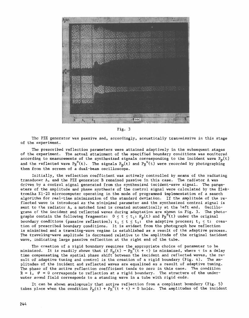
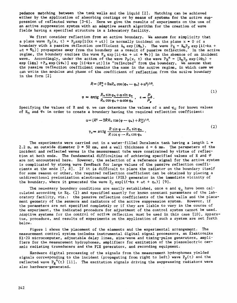
Fig. 3
The PIE generator was passive and, accordingly, acoustically transmissive in this stage of the experiment.
The prescribed reflection parameters were attained adaptively in the subsequent stages of the experiment. The actual attainment of the specified boundary conditions was monitored according to measurements of the synthesized signals corresponding to the incident wave Pp(t)
and the reflected wave PR*(t). The signals Pp(t) and PR*(t) were recorded by photographing
them from the screen of a dual-beam oscilloscope.
Initially, the reflection coefficient was actively controlled by means of the radiating transducer A, and the PIE generator B remained passive in this case. The radiator A was driven by a control signal generated from the synthesized incident-wave signal. The par@m- eters of the amplitude and phase synthesis of the control signal were calculated by the Elek- tronika KI-20 microcomputer operating in the mode of programmed implementation of a search algorithm for real-time minimization of the standard deviation. If the amplitude of the re- flected wave is introduced as the minimized parameter and the synthesized control signal is sent to the radiator A, a matched load is created automatically at the left end. Oscillo- grams of the incident and reflected waves during adaptation are shown in Fig. 3. The photo- graphs contain the following fragments: 0 ~ t ~ tl: Pp(t) and PR*(t) under the original
boundary conditions (passive reflection); t I S t 5 t2: the adaptive process; t 2 ! t: crea- tion of prescribed boundary conditions. It is evident from the photograph how reflection is minimized and a traveling-wave regime is established as a result of the adaptive process. The traveling-wave amplitude is decreased relative to the amplitude of the original incident wave, indicating large passive reflection at the right end of the tube.
The creation of a rigid boundary requires the appropriate choice of parameter to be minimized. It is readily shown that if Pp(t) - PR*(t + T) is minimized, where ~ is a delay time compensating the spatial phase shift between the incident and reflected waves, the re- sult of adaptive tuning and control is the creation of a rigid boundary (Fig. 4). The am- plitudes of the incident and reflected waves are equalized as a result of adaptive tuning. The phase of the active reflection coefficient tends to zero in this case. The condition R = i, ~ = 0 corresponds to reflection at a rigid boundary. The structure of the under- water sound field corresponds to a standing wave in a tube with rigid ends.
It can be shown analogously that active reflection from a compliant boundary (Fig. 5) takes place when the condition Pp(t) + PR*(t + ~) = 0 holds. The amplitudes of the incident
244
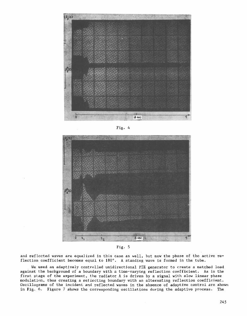
Fig. 4
Fig. 5
and reflected waves are equalized in this case as well, but now the phase of the active re- flection coefficient becomes equal to 180 ~ . A standing wave is formed in the tube.
We used an adaptively controlled unidirectional PIE generator to create a matched load against the background of a boundary with a time-varying reflection coefficient. As in the first stage of the experiment, the radiator A is driven by a signal with slow linear phase modulation, thus creating a reflecting boundary with an alternating reflection coefficient. Oscillograms of the incident and reflected waves in the absence of adaptive control are shown in Fig. 6. Figure 7 shows the corresponding oscillations during the adaptive process. The
245
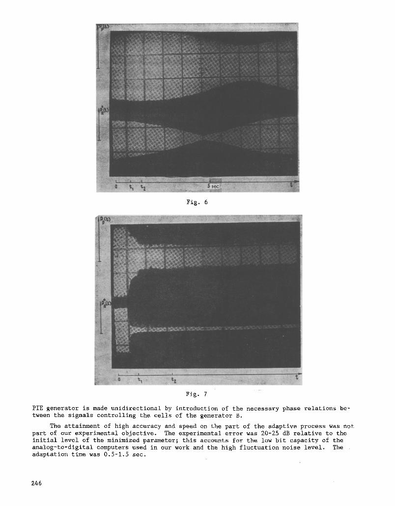
Fig. 6
Fig. 7
PIE generator is made unidirectional by introduction of the necessary phase relations be- tween the signals controlling the cells of the generator B.
The attainment of high accuracy and speed on the part of the adaptive process was not part of our experimental objective. The experimental error was 20-25 dB relative to the initial level of the minimized parameter; this accounts for the low bit capacity of the analog-to-digital computers used in our work and the high fluctuation noise level. The adaptation time was 0.5-1.5 sec.
246
In our opinion, therefore, the applicatio~iof~suqhasYstem:for controlling the struc- ture of an underwater sound field'in a specially constructed measurement waveguide provides a simple and effective means for obtaining the boundary conditions required for experimental work.
LITERATURE CITED
i. I. I. Klyukin and A. E. Kolesnikov, Acoustical Measurements in Shipbuilding [in Russian], Sudostroenie, Leningrad (1966).
2. L. M. Brekhovskikh and Yu. P. Lysanov, Fundamentals of Ocean Acoustics, Springer-Verlag, Berlin-New York (1982).
3. A. I. Vyalyshev and B. D. Tartakovskii, in: Vibrations, Radiation, and Damping of Elastic Structures [in Russian], Nauka, Moscow (1973).
4. A. A. Mazanikov and V. V. Tyutekin, Akust. Zh., 20, No. 5, 807 (1974). 5. S. P. Klimov, Dissertation, Akust. Inst. Akad. Nauk SSSR, Moscow (1980). 6. V. V. Tyutekin, A. E. Vovk, and S. P. Klimov, Inventor's Certificate No. 602,988; Byull.
Izobret., No. 14, 197 (1978). 7. A. A. Mazanikov and V. V. Tyutekin, Akust. Zh., 24, No. 5, 788 (1978). 8. A. A. Mal'tsev and Arzamasov, Izv. Vyssh. Uchebn. Zaved., Radiofiz., 25, No. 6, 657
(1982). A. N. Malakhov and V. V. Cherepennikov, Akust. Zh., 32, No. 3, 411 (1986). Ya. Z. Tsypkin, Adaptation and Training in Automatic Systems [in Russian], Nauka, Moscow (1968). U. S. Patent No. 3,346,067 (October 1967). A. N. Malakhov and V. V. Cherepennikov, Izv. Vyssh. Uchebn. Zaved., Radiofiz., 27, No. 10, 1349 (1984).
9. i0.
ii. 12.
DIFFRACTION OF A PLANAR ELECTROMAGNETIC WAVE
BY A DIELECTRIC CONE
E. N. Vasil'ev, Z. V. Sedel'nikova, and A. R. Seregina
UDC 538.574.6
The integral equation numerical method is used to solve the problem of diffrac- tion of a planar electromagnetic wave on a dielectric cone, with the direction of the plane wave noncoincident with the cone axis. Calculation results and a detailed analysis are presented.
The integral equation method can be used to solve the problem of diffraction of electro- magnetic waves on dielectric bodies of rotation. This method has been used to study the phe- nomena of plane wave diffraction on a cylinder (for axial [i] and oblique [2] incidence) and on a cone for axial incidence [3]. The present study will offer results for oblique inci- dence of a plane wave on a dielectric cone.
In order to simplify calculations in the case of a body of rotation all fields and cur- rents can be expanded in Fourier series in the azimuthal coordinate, and the integral equa- tion is constructed in terms of harmonics of equivalent currents on the cone surface. This equation has been obtained for an arbitrary body of rotation and has the form
A
0
Moscow Energy Institute. Translated from Izvestiya Vysshikh Uchebnykh Zavedenii, Radio- fizika, Vol. 31, No. 3, pp. 334-342, March, 1988. Original article submitted April 11, 1986.
0033-8443/88/3103-0247512.50 �9 1988 Plenum Publishing Corporation 247