Embed Size (px)
Citation preview

WaveguideSwitches
High precision mechanical Microwave Products

Sivers Lab AB Stockholm Sweden, Waveguide Switch Catalogue
Issue 1:2004
Technical data in this catalogue are subject to change without noticeand become contractual only after written confirmation.

3
Waveguide Acuator Isolation Type no Page WR229/R40/WG11A Latching 80 WS8286A/00 10 WR284/R32/WG10 Latching 80 WS8286S/00 12 WR187/R48/WG12 Latching 80 WS8286G/00 14 WR112/R84/WG15 Latching 80 WS8086H/00 16 Fail-safe 80 WS8087H/00 18 Latching 80 WS8186H/00 20 Latching 80 WS8186H/70 22 WR137/R70/WG14 Latching 75 WS8186J/00 24 Latching 75 WS8186J/70 26 WR90/R100/WG126 Latching 90 WS8086X/00 28 Fail-safe 90 WS8087X/00 30 Fail-safe 60 WS8088X/00 32 Latching 60 WS8089X/00 34 Latching 60 WS8189X/00 36 WR75/R120/WG17 Latching 90 WS8086M/00 38 Fail-safe 90 WS8087M/00 40 Latching 60 WS8089M/00 42 Latching 60 WS8189M/00 44 Latching 60 WS8189M/70 46 WR62/R140/WG18 Latching 90 WS8086P/00 48 Fail-safe 90 WS8087P/00 50 Fail-safe 60 WS8088P/00 52 Latching 60 WS8089P/00 54 Latching 60 WS8189P/00 56 Latching 60 WS8189P/70 58 WR42/R220/WG20 Latching 70 WS8189K/00 60 WR28/R320/WG22 Latching 60 WS8089Q/00 61 WRD580 Latching 50 WS8189D58/00 64 WRD650 Latching 50 WS8089D6/00 66 WRD750 Latching 40 WS8089D7/00 68
See also Sivers Standard Flange dimensions 70
Other ModelsOn account of our module design we are prepared for modifications for any special requirements please contact us or look for your local dealer at www.siverslab.se
E-mail: [email protected] Fax: +46 8 751 00 19 Phone:+46 8 477 68 00
Data Sheet Overview

Waveguide Switches
General
This catalogue describes the design of standard manual and automatic waveguide switches.Switches are available in frequencies ranging from 2.6 to 40 GHz.
Other models and special designs are available on request.
Waveguide switches are widely used in microwave systems:
• In radars for redundancy transmitters
• In radars for connection to high power dummy load
• In radars for test purposes
• In satellite communications for redundancy applications
• In test systems to select various signal paths etc.
Common to all Sivers Lab mechanical waveguide switches are:
• High isolation
• Low insertion loss
• High power capability
• Long life

5
General Design
The switches have a square stator with four waveguide ports. The rotor, which is fitted in the stator, has two or three channels. Electrical continuity between rotor and stator is achieved by means of quarter wave chokes. These chokes give extremely high isolation between the channels and also ensure unchanged high electrical performance throughout the lifetime of the switch.
All models have low VSWR and high power handling capacity. They withstand the full power rating of the waveguide and most models can be pressurised to 0.2 MPa (2 ATO) for high peak power applications.
All switches have E-plane bends for small dimensions.
The switches are made of copper-free aluminium alloy, which is chromated. The rotor is supported by stainless steel ball bearings.
The flange connections are, for most models, standard flat flanges with threaded holes. Special flange drilling and/or helicoil steel inserts are available on request.
Switches are available with:
• standard rectangular waveguides
• double-ridge waveguides

Configuration
All switches have a square stator with four ports. The rotor has two channels.
Four ports – two channels (transfer).
Position 1 Position 2
Actuators
Manual and automatic (electromagnetic) actuators are available.
The automatic types are fail-safe or latching. The fail-safe type returns to the de-energized position when the power is disconnected and requires a small holding current in the energized position. The latching type is stabile in both positions without holding current.
In applications like safety-circuits, where it is required that the switch returns to its original position, if power supply fails, a fail-safe type is the natural choice. In other applications it might be an advantage to have low power consumption and no holding current.
Several models of automatic actuators are avail-able for switches in the frequency range 4 to 40 GHz. All standard models operate at 28 Volts and have a maximum switch current of 1 Ampere and a maximum holding current of 0.3 Ampere.
For all latching models the current is automatically switched off when the rotor is in position. In fail-safe models the current is automatically reduced to holding current when the rotor is in position.
One or several sets of position indicators are available with all models of actuators.
Some models can be supplied with manual override knob for manual setting of position.
Standard Model. Type number 80--.These models have the smallest dimensions. They have one set of position indicators and the electrical connection is via soldering pins or circular MIL- connector. Switch time is 100 to 250 ms (depending on frequency band). The models are in most cases specified for full temperature range.
SatCom Model. Type number 81--.This model can be supplied with up to four sets of position indicators. One set of indicators can be arranged to have "inhibit" function, which is a closed contact at end positions and an open contact during transition. The actuator has manual override and cannot be pressurized. Switch time is 100 to 150 ms. The electrical connection is via a circular MIL- connector.
Fail Safe MechanismHolding current in one position
Latching MechanismNo holding current in any position

7
Technical Data
VSWR 1.05 to 1.08 for rectangular waveguides and 1.20 for double ridge models.
Insertion Loss < 0.1 dB power capacity, except for double ridge models,which have 0.2 to 0.4 dB) . See datasheets for each model.
Flanges MIL-F-3299 for rectangular waveguides and MIL-F-39000 for double ridge waveguides.
Actuator voltage 28±3 V DC as standard. Some models may have a different voltage.
Actuator current 1 A for standard models. Switch time 100 to 1000 ms depending on model.
Position indicators 60 V/ 500 mA rating.
Connectors Soldering pins, flying lead or circular MIL connector according to datasheet.
Pressurization Max. 0.2 MPa (not for 81-- models).
Leakage Max. 10 cc/minute.
Material Stator and rotor; aluminium alloy copper free.
Finish Stator and rotor; Chromate per MIL-C-5541C.
Life 250 000 actuations minimum.
Temperature range -40 to +85°C operating except 81-- models which have 0 to 50°C.
Vibration 10 G for standard models. Up to 30 G for special models.
Duty 2 actuations/second at temperatures up to +40°C decreasing to one actuation/2 seconds at +85°C.
Reliability All switches are actuated and the function monitored for 1 000 actuations at room temperature, highest and lowest specified temperature.

The Company
Sivers is a long-established European microwave product manufacturer located in Sweden's largest high-tech area, Kista, in the northern part of Stockholm.Carl von Sivers founded the company in 1951. With more than 50 years experience in microwaves, Sivers is a world-leading manufacturer of Waveguide Switches. The 2 000 sq. meters (20 000 sq. feet) facilities contain state-of-art technologies and equip-ment for development, engineering and production. These facilities allow the necessary activities in-house with short lead times and full quality control providing both standard and customised products
Development and production are supported by CAD/CAM systems with highly automated production equip-ment for low as well as large quantity production. All activities are guided by a Quality System that complies with ISO-9001:2000.
In addition to common microwave and mechanical test equipment Sivers has also equipment for high power tests, random vibration, burn-in, temperature cycling, low noise measurements etc.
Sivers forms a part of the Chelton Group, a division of Cobham Plc.
Cobham Plc is a substantial British industrial group with companies in Europe and North America, employing over 8 900 people and with a turnover of 832 million GBP (2003). Cobham is internationally known as a key supplier to aeronautical and defence industries, particularly in the field of RF and micro-wave.
The capabilities of the group, particularly the very close co-operation with the leading slipring manufacturer Air Precision, allow Sivers to further improve its commercial technical performance and thus offer you an even better service.
Quality
Sivers is fully certified as per ISO-9001:2000 and quality remains one of Sivers’ main priorities.
With its qualified engineers and sophisticated test equipment Sivers constantly seeks to maintain and improve the quality of products by application of ISO 9001:2000 procedures and instructions.
The Quality Assurance Department is completely involved in all stages of the design, development and manufacturing of our products.
Each product delivered can be accompanied by an individual test document. Our Quality Manager certifies the quality by a Certificate of Conformance.

9
Specifications

F
E
D
C
B
A
1 2 3 4 5
Ref.
Chkd.
Appvd.
Designed
Sign.
Sign.
Sign.
Sheet Scale Issue
Doc. no.SIVERS
Dimensions in mm Title
Europ. proj.
UNLESS OTHERWISE STATED THE FOLLOWING APPLIES:
General tolerances, linear and angular dimensions: ISO 2768-c Drawing principle
Tolerancing principle
SS 1902
ISO 8015
This
docu
ment
is ou
r pro
perty
and s
hall n
ot wi
thout
our w
ritten
perm
ission
be al
tered
, cop
ied or
comm
unica
ted to
a thi
rd pa
rty.
c
SIVE
RS LA
B AB
CAD-
doku
ment
Får e
j revid
eras
man
uellt Modification Date Sign.Issue Chkd.
020410 CEl
B1:2WS8286A/01
WAVEGUIDE SWITCHWR229 / A-band Latching
2(2)
B Paragraphs added 2003-1014 HNg
Ctrl. circ.
Top wievAB
C
D
EF
Pos I
Pos II
Com
Shown in Pos I (A actuaed)
GHJ
KLM
NP
Pos.Ind. 1
Pos.Ind. 1
Pos.Ind. 1
INHIBIT
CAUTION!ESD SENSITIVE
Opened during VSWR >1,2
60,3
120
190
70
70
87,63q
4x M6Depth min 6
MANUAL OVERRIDE
l O 0,2
HW
SIVERS Reference Approved Origin date Issue date Issue Page Document HNg HW 2002-04-10 2003-11-05 B 2 (2) WS 8286A/01 ___________________________________________________________________________________________________
RF DATA
Frequency range 3.3 – 4.9 GHz VSWR 1.05 Insertion loss 0.1 dB Isolation 80 dB Peak power 500 kW at 0.1 MPa abs., +25°C Average power 4 kW Flange interface MIL-DTL-3922/52C-012
Modified with M6, thread depth min 8
ACTUATOR DATA
Operating voltage 28±3 VDC Operating current 1 A Switching time 200 ms Duty (min time between 500 ms -20°C to +40°C successive operations) linearly increasing to 1 s at +85°C Connector MS 3112E 14-19P Mating connector MS 3116F 14-19S or eq.
POSITION INDICATOR
Position indicator current 30 V Max, 100 mA Max Resistive load Position indicator Three sets of C-form contacts and one set of inhibit contact, opened during VSWR >1.2
MECHANICAL DATA
Material Aluminium alloy, Cu free Finishing Chromate per MIL-C-5541 and black painted Air pressure 0.1 MPa overpr. Max Air leakage 10 cm3/min (0.1 MPa overpr.) Max Weight 2 kg Max Life 250 000 actuations
ENVIRONMENTAL DATA
Ambient temperature -20°C to +85°C Vibration 5 – 18 Hz, 3 mm amplitude 18 – 2000 Hz, 15 g ___________________________________________________________________________________ This document must not be copied without our written permission, and the contents thereof must not be imparted to a third party WS 8286A/01

11
SIVERS Reference Approved Origin date Issue date Issue Page Document HNg HW 2002-04-10 2003-11-05 B 2 (2) WS 8286A/01 ___________________________________________________________________________________________________
RF DATA
Frequency range 3.3 – 4.9 GHz VSWR 1.05 Insertion loss 0.1 dB Isolation 80 dB Peak power 500 kW at 0.1 MPa abs., +25°C Average power 4 kW Flange interface MIL-DTL-3922/52C-012
Modified with M6, thread depth min 8
ACTUATOR DATA
Operating voltage 28±3 VDC Operating current 1 A Switching time 200 ms Duty (min time between 500 ms -20°C to +40°C successive operations) linearly increasing to 1 s at +85°C Connector MS 3112E 14-19P Mating connector MS 3116F 14-19S or eq.
POSITION INDICATOR
Position indicator current 30 V Max, 100 mA Max Resistive load Position indicator Three sets of C-form contacts and one set of inhibit contact, opened during VSWR >1.2
MECHANICAL DATA
Material Aluminium alloy, Cu free Finishing Chromate per MIL-C-5541 and black painted Air pressure 0.1 MPa overpr. Max Air leakage 10 cm3/min (0.1 MPa overpr.) Max Weight 2 kg Max Life 250 000 actuations
ENVIRONMENTAL DATA
Ambient temperature -20°C to +85°C Vibration 5 – 18 Hz, 3 mm amplitude 18 – 2000 Hz, 15 g ___________________________________________________________________________________ This document must not be copied without our written permission, and the contents thereof must not be imparted to a third party WS 8286A/01

F
E
D
C
B
A
1 2 3 4 5
Ref.
Chkd.
Appvd.
Designed
Sign.
Sign.
Sign.
Sheet Scale Issue
Doc. no.SIVERS
Dimensions in mm Title
Europ. proj.
UNLESS OTHERWISE STATED THE FOLLOWING APPLIES:
General tolerances, linear and angular dimensions: ISO 2768-c Drawing principle
Tolerancing principle
SS 1902
ISO 8015
This
docu
ment
is ou
r pro
perty
and s
hall n
ot wi
thout
our w
ritten
perm
ission
be al
tered
, cop
ied or
comm
unica
ted to
a thi
rd pa
rty.
c
SIVE
RS LA
B AB
CAD-
doku
ment
Får e
j revid
eras
man
uellt Modification Date Sign.Issue Chkd.
2003-1113 HNg
A1:2WS8286S/00
WAVEGUIDE SWITCHWR284/R32/WG10 Latching
1 (2)
CAUTION!ESD SENSITIVE
Ctrl. circ.
Top wievAB
C
D
EF
Pos I
Pos II
Com
Pos.
Ind.
Shown in Pos I (A actuaed)
63,5
130
210
MAX
80
80
107,95q
4x M6Depth min 6l O 0,2
HW
SIVERS Reference Approved Origin date Issue date Issue Page Document HNg HW 2003-11-13 2003-11-13 A 2 (2) WS 8286S/00 ___________________________________________________________________________________________________
RF DATA
Frequency range 2.6 – 3.95 GHz VSWR 1.05 Insertion loss 0.1 dB Isolation 80 dB Peak power 1 MW at 0.1 MPa abs., +25°C Average power 8 kW Flange interface MIL-DTL-3922/52C-032
Modified with M6, thread depth min 8
ACTUATOR DATA
Operating voltage 28±3 V DC Operating current 1 A, Self cut off Switching time 200 ms Duty (min time between 500 ms -20°C to +40°C successive operations) linearly increasing to 2 s at +70°C Connector MS 3112E 10-6P Mating connector MS 3116F 10-6S or eq.
POSITION INDICATOR
Voltage / Current 30 V Max, 100 mA Max Resistive load
MECHANICAL DATA
Material Aluminium alloy, Cu free Finish Chromate per MIL-C-5541 and black painted Air pressure 0.1 MPa overpr. Max Air leakage 10 cm3/min (0.1 MPa overpr.) Max Weight 2.5 kg Max Life 250 000 actuations
ENVIRONMENTAL DATA
Ambient temperature -20°C to +70°C Vibration 5 – 18 Hz, 3 mm amplitude 18 – 2000 Hz, 15 g Humidity 100%RH if dry air in waveguide ___________________________________________________________________________________ This document must not be copied without our written permission, and the contents thereof must not be imparted to a third party nor be used for any unauthorized purpose. © Sivers Lab AB, Sweden WS 8286S/00

13
SIVERS Reference Approved Origin date Issue date Issue Page Document HNg HW 2003-11-13 2003-11-13 A 2 (2) WS 8286S/00 ___________________________________________________________________________________________________
RF DATA
Frequency range 2.6 – 3.95 GHz VSWR 1.05 Insertion loss 0.1 dB Isolation 80 dB Peak power 1 MW at 0.1 MPa abs., +25°C Average power 8 kW Flange interface MIL-DTL-3922/52C-032
Modified with M6, thread depth min 8
ACTUATOR DATA
Operating voltage 28±3 V DC Operating current 1 A, Self cut off Switching time 200 ms Duty (min time between 500 ms -20°C to +40°C successive operations) linearly increasing to 2 s at +70°C Connector MS 3112E 10-6P Mating connector MS 3116F 10-6S or eq.
POSITION INDICATOR
Voltage / Current 30 V Max, 100 mA Max Resistive load
MECHANICAL DATA
Material Aluminium alloy, Cu free Finish Chromate per MIL-C-5541 and black painted Air pressure 0.1 MPa overpr. Max Air leakage 10 cm3/min (0.1 MPa overpr.) Max Weight 2.5 kg Max Life 250 000 actuations
ENVIRONMENTAL DATA
Ambient temperature -20°C to +70°C Vibration 5 – 18 Hz, 3 mm amplitude 18 – 2000 Hz, 15 g Humidity 100%RH if dry air in waveguide ___________________________________________________________________________________ This document must not be copied without our written permission, and the contents thereof must not be imparted to a third party nor be used for any unauthorized purpose. © Sivers Lab AB, Sweden WS 8286S/00

1(1) F
E
D
C
B
A
1 2 3 4 5
Ref.
Chkd.
Appvd.
Designed
Sign.
Sign.
Sign.
Sheet Scale Issue
Doc. no.SIVERS
Dimensions in mm Title
Europ. proj.
UNLESS OTHERWISE STATED THE FOLLOWING APPLIES:
General tolerances, linear and angular dimensions: ISO 2768-c Drawing principle
Tolerancing principle
SS 1902
ISO 8015
This
docu
ment
is ou
r pro
perty
and s
hall n
ot wi
thout
our w
ritten
perm
ission
be al
tered
, cop
ied or
comm
unica
ted to
a thi
rd pa
rty.
c
SIVE
RS LA
B AB
CAD-
doku
ment
Får e
j revid
eras
man
uellt Modification Date Sign.Issue Chkd.
030630 SKm
1:1,5 B
WS8286G/00
WAVEGUIDE SWITCHWR187/R48/WG12 Latching
B ECO 2003-1014 HNg
CAUTION!ESD SENSITIVE
Ctrl. circ.
Top wievAB
C
D
EF
Pos I
Pos II
Com
Pos.
Ind.
Shown in Pos I (A actuaed)
49,2
165
MAX
57,15
57,15
74,93
74,93
4x M5Depth min 8l O 0,2
HW
HWHW
SIVERS Reference Approved Origin date Issue date Issue Page Document HNg HW 2003-06-30 2003-11-04 B 2 (2) WS 8286G/00 ___________________________________________________________________________________________________
RF DATA
Frequency range 3.95 – 5.85 GHz VSWR 1.05 Insertion loss 0.1 dB Isolation 80 dB Peak power 500 kW at 0.1 MPa abs., +25°C Average power 4 kW Flange interface MIL-DTL-3922/52C-014
Modified with M6, thread depth min 8
ACTUATOR DATA
Operating voltage 28±3 V DC Operating current 1 A, Self cut off Switching time 500 ms Duty (min time between 500 ms -20°C to +40°C successive operations) linearly increasing to 2 s at +70°C Connector MS 3112E 10-6P Mating connector MS 3116F 10-6S or eq.
POSITION INDICATOR
Voltage / Current 30 V Max, 100 mA Max Resistive load
MECHANICAL DATA
Material Aluminium alloy, Cu free Finishing Chromate per MIL-C-5541 and black painted Air pressure 0.1 MPa overpr. Max Air leakage 10 cm3/min (0.1 MPa overpr.) Max Weight 1.5 kg Max Life 250 000 actuations
ENVIRONMENTAL DATA
Ambient temperature -20°C to +70°C Vibration 5 – 18 Hz, 3 mm amplitude 18 – 2000 Hz, 15 g Humidity 100%RH if dry air in waveguide _____________________________________________________________________________________This document must not be copied without our written permission, and the contents thereof must not be imparted to a third party nor be used for any unauthorized purpose. © Sivers Lab AB, Sweden WS 8286G/00

15
SIVERS Reference Approved Origin date Issue date Issue Page Document HNg HW 2003-06-30 2003-11-04 B 2 (2) WS 8286G/00 ___________________________________________________________________________________________________
RF DATA
Frequency range 3.95 – 5.85 GHz VSWR 1.05 Insertion loss 0.1 dB Isolation 80 dB Peak power 500 kW at 0.1 MPa abs., +25°C Average power 4 kW Flange interface MIL-DTL-3922/52C-014
Modified with M6, thread depth min 8
ACTUATOR DATA
Operating voltage 28±3 V DC Operating current 1 A, Self cut off Switching time 500 ms Duty (min time between 500 ms -20°C to +40°C successive operations) linearly increasing to 2 s at +70°C Connector MS 3112E 10-6P Mating connector MS 3116F 10-6S or eq.
POSITION INDICATOR
Voltage / Current 30 V Max, 100 mA Max Resistive load
MECHANICAL DATA
Material Aluminium alloy, Cu free Finishing Chromate per MIL-C-5541 and black painted Air pressure 0.1 MPa overpr. Max Air leakage 10 cm3/min (0.1 MPa overpr.) Max Weight 1.5 kg Max Life 250 000 actuations
ENVIRONMENTAL DATA
Ambient temperature -20°C to +70°C Vibration 5 – 18 Hz, 3 mm amplitude 18 – 2000 Hz, 15 g Humidity 100%RH if dry air in waveguide _____________________________________________________________________________________This document must not be copied without our written permission, and the contents thereof must not be imparted to a third party nor be used for any unauthorized purpose. © Sivers Lab AB, Sweden WS 8286G/00

1 (2)
57,15
F
E
D
C
B
A
1 2 3 4 5
Ref.
Chkd.
Appvd.
Designed
Sign.
Sign.
Sign.
Sheet Scale Issue
Doc. no.SIVERS
Dimensions in mm Title
Europ. proj.
UNLESS OTHERWISE STATED THE FOLLOWING APPLIES:
General tolerances, linear and angular dimensions: ISO 2768-c Drawing principle
Tolerancing principle
SS 1902
ISO 8015
This
docu
ment
is ou
r pro
perty
and s
hall n
ot wi
thout
our w
ritten
perm
ission
be al
tered
, cop
ied or
comm
unica
ted to
a thi
rd pa
rty.
c
SIVE
RS LA
B AB
CAD-
doku
ment
Får e
j revid
eras
man
uellt Modification Date Sign.Issue Chkd.
030108 CEl
1:1,5 BWS8086H/00
43
HWHW
WAVEGUIDE SWITCHWR112/R84/WG15 Latching
B ECO 2003-1016 HNg
Ctrl. circ.
Top viewAB
C
D
EF
Pos I
Pos II
Com
Pos.
Ind.
Shown in Pos I (A actuated)
CAUTION!ESD SENSITIVE
43 57,15
4x M4Depth min 4l O 0,2
NAME LABEL
25,5
74
94,6
HW
SIVERS Reference Approved Origin date Issue date Issue Page Document HNg HW 2003-01-08 2003-11-03 B 2 (2) WS 8086H/00 ___________________________________________________________________________________________________
RF DATA
Frequency range 7.05 – 10.0 GHz VSWR 1.10 Insertion loss 0.1 dB Isolation 80 dB Peak power 350 kW at 0.1 MPa abs., +25°C Average power 4 kW Flange interface MIL-DTL-3922/53D-004
Modified with M4, thread depth min 5
ACTUATOR DATA
Operating voltage 28±3 V DC Operating current 1 A, Self cut off Switching time 300 ms Duty (min time between 500 ms -40°C to +40°C successive operations) linearly increasing to 2 s at +85°C Connector MS 3112E 10-6P Mating connector MS 3116F 10-6S or eq.
POSITION INDICATOR
Voltage / Current 30 V Max, 100 mA Max Resistive load
MECHANICAL DATA
Material Aluminium alloy, Cu free Finishing Chromate per MIL-C-5541 and black painted Air pressure 0.1 MPa overpr. Max Air leakage 10 cm3/min (0.1 MPa overpr.) Max Weight 0.5 kg Max Life 250 000 actuations
ENVIRONMENTAL DATA
Ambient temperature -40°C to +85°C Vibration 5 – 18 Hz, 3 mm amplitude 18 – 2000 Hz, 15 g Humidity 100%RH if dry air in waveguide ___________________________________________________________________________________ This document must not be copied without our written permission, and the contents thereof must not be imparted to a third party nor be used for any unauthorized purpose. © Sivers Lab AB, Sweden WS 8086H/00

17
SIVERS Reference Approved Origin date Issue date Issue Page Document HNg HW 2003-01-08 2003-11-03 B 2 (2) WS 8086H/00 ___________________________________________________________________________________________________
RF DATA
Frequency range 7.05 – 10.0 GHz VSWR 1.10 Insertion loss 0.1 dB Isolation 80 dB Peak power 350 kW at 0.1 MPa abs., +25°C Average power 4 kW Flange interface MIL-DTL-3922/53D-004
Modified with M4, thread depth min 5
ACTUATOR DATA
Operating voltage 28±3 V DC Operating current 1 A, Self cut off Switching time 300 ms Duty (min time between 500 ms -40°C to +40°C successive operations) linearly increasing to 2 s at +85°C Connector MS 3112E 10-6P Mating connector MS 3116F 10-6S or eq.
POSITION INDICATOR
Voltage / Current 30 V Max, 100 mA Max Resistive load
MECHANICAL DATA
Material Aluminium alloy, Cu free Finishing Chromate per MIL-C-5541 and black painted Air pressure 0.1 MPa overpr. Max Air leakage 10 cm3/min (0.1 MPa overpr.) Max Weight 0.5 kg Max Life 250 000 actuations
ENVIRONMENTAL DATA
Ambient temperature -40°C to +85°C Vibration 5 – 18 Hz, 3 mm amplitude 18 – 2000 Hz, 15 g Humidity 100%RH if dry air in waveguide ___________________________________________________________________________________ This document must not be copied without our written permission, and the contents thereof must not be imparted to a third party nor be used for any unauthorized purpose. © Sivers Lab AB, Sweden WS 8086H/00

1 (2)
57,15
F
E
D
C
B
A
1 2 3 4 5
Ref.
Chkd.
Appvd.
Designed
Sign.
Sign.
Sign.
Sheet Scale Issue
Doc. no.SIVERS
Dimensions in mm Title
Europ. proj.
UNLESS OTHERWISE STATED THE FOLLOWING APPLIES:
General tolerances, linear and angular dimensions: ISO 2768-c Drawing principle
Tolerancing principle
SS 1902
ISO 8015
This
docu
ment
is ou
r pro
perty
and s
hall n
ot wi
thout
our w
ritten
perm
ission
be al
tered
, cop
ied or
comm
unica
ted to
a thi
rd pa
rty.
c
SIVE
RS LA
B AB
CAD-
doku
ment
Får e
j revid
eras
man
uellt Modification Date Sign.Issue Chkd.
2003-1112 HNg
1:1,5 AWS8087H/00
43
HWHW
WAVEGUIDE SWITCHWR112/R84/WG15 Fail-safe
CAUTION!ESD SENSITIVE
43 57,15
4x M4Depth min 4l O 0,2
NAME LABEL
25,5
74
94,6
Ctrl. circ.
Top wiev
C
B
A
F
E
D
NC
Pos II
Com
Pos.
Ind.
Shown in de-energized position
R
SIVERS Reference Approved Origin date Issue date Issue Page Document HNg HW 2003-11-12 2003-11-12 A 2 (2) WS 8087H/00 ___________________________________________________________________________________________________
RF DATA
Frequency range 7.05 – 10.0 GHz VSWR 1.10 Insertion loss 0.1 dB Isolation 80 dB Peak power 350 kW at 0.1 MPa abs., +25°C Average power 4 kW Flange interface MIL-DTL-3922/53D-004
Modified with M4, thread depth min 5
ACTUATOR DATA
Operating voltage 28±3 V DC Operating current 1 A, Auto switch on to holding current after 200 ms Holding current 300 mA Switching time 300 ms Duty (min time between 500 ms -40°C to +40°C successive operations) linearly increasing to 2 s at +85°C Connector MS 3112E 10-6P Mating connector MS 3116F 10-6S or eq.
POSITION INDICATOR
Voltage / Current 30 V Max, 100 mA Max Resistive load
MECHANICAL DATA
Material Aluminium alloy, Cu free Finishing Chromate per MIL-C-5541 and black painted Air pressure 0.1 MPa overpr. Max Air leakage 10 cm3/min (0.1 MPa overpr.) Max Weight 0,5 kg Max Life 250 000 actuations
ENVIRONMENTAL DATA
Ambient temperature -40°C to +85°C Vibration 5 – 18 Hz, 3 mm amplitude 18 – 2000 Hz, 15 g Humidity 100%RH if dry air in waveguide ___________________________________________________________________________________ This document must not be copied without our written permission,
WS 8087H/00

19
SIVERS Reference Approved Origin date Issue date Issue Page Document HNg HW 2003-11-12 2003-11-12 A 2 (2) WS 8087H/00 ___________________________________________________________________________________________________
RF DATA
Frequency range 7.05 – 10.0 GHz VSWR 1.10 Insertion loss 0.1 dB Isolation 80 dB Peak power 350 kW at 0.1 MPa abs., +25°C Average power 4 kW Flange interface MIL-DTL-3922/53D-004
Modified with M4, thread depth min 5
ACTUATOR DATA
Operating voltage 28±3 V DC Operating current 1 A, Auto switch on to holding current after 200 ms Holding current 300 mA Switching time 300 ms Duty (min time between 500 ms -40°C to +40°C successive operations) linearly increasing to 2 s at +85°C Connector MS 3112E 10-6P Mating connector MS 3116F 10-6S or eq.
POSITION INDICATOR
Voltage / Current 30 V Max, 100 mA Max Resistive load
MECHANICAL DATA
Material Aluminium alloy, Cu free Finishing Chromate per MIL-C-5541 and black painted Air pressure 0.1 MPa overpr. Max Air leakage 10 cm3/min (0.1 MPa overpr.) Max Weight 0,5 kg Max Life 250 000 actuations
ENVIRONMENTAL DATA
Ambient temperature -40°C to +85°C Vibration 5 – 18 Hz, 3 mm amplitude 18 – 2000 Hz, 15 g Humidity 100%RH if dry air in waveguide ___________________________________________________________________________________ This document must not be copied without our written permission,
WS 8087H/00

1 (2)
25,5
57,15q
F
E
D
C
B
A
1 2 3 4 5
Ref.
Chkd.
Appvd.
Designed
Sign.
Sign.
Sign.
Sheet Scale Issue
Doc. no.SIVERS
Dimensions in mm Title
Europ. proj.
UNLESS OTHERWISE STATED THE FOLLOWING APPLIES:
General tolerances, linear and angular dimensions: ISO 2768-c Drawing principle
Tolerancing principle
SS 1902
ISO 8015
This
docu
ment
is ou
r pro
perty
and s
hall n
ot wi
thout
our w
ritten
perm
ission
be al
tered
, cop
ied or
comm
unica
ted to
a thi
rd pa
rty.
c
SIVE
RS LA
B AB
CAD-
doku
ment
Får e
j revid
eras
man
uellt Modification Date Sign.Issue Chkd.
020430 CEl
BWS8186H/00
HWHW
WAVEGUIDE SWITCHWR112R84/WG15 Latching
B ECO 2003-1016 HNg
1:1,5
4343
109
101
125
Ctrl. circ.
Top wievAB
C
D
EF
Pos I
Pos II
Com
Shown in Pos I (A actuaed)
GHJ
KLM
NP
Pos.Ind. 1
INHIBITOpened during VSWR >1,2
CAUTION!ESD SENSITIVE
4x M4Depth min 4
MANUAL OVERRIDE
l O 0,2
Ctrl. circ.
Top wievAB
C
D
EF
Pos I
Pos II
Com
Shown in Pos I (A actuaed)
GHJ
KLM
NP
Pos.Ind. 1
Pos.Ind. 2
Pos.Ind. 3
INHIBITOpened during VSWR >1,2
CAUTION!ESD SENSITIVE
HW
SIVERS Reference Approved Origin date Issue date Issue Page Document HNg HW 2002-04-30 2003-11-05 B 2 (2) WS 8186H/00 ___________________________________________________________________________________________________
RF DATA
Frequency range 7.05 – 10.0 GHz VSWR 1.10 Insertion loss 0.1 dB Isolation 80 dB Peak power 350 kW at 0.1 MPa abs., +25°C Average power 4 kW Flange interface MIL-DTL-3922/53D-004
Modified with M4, thread depth min 5
ACTUATOR DATA
Operating voltage 28±3 V DC Operating current 1 A, Self cut off Switching time 250 ms Duty (min time between 500 ms -20°C to +40°C successive operations) linearly increasing to 2 s at +70°C Connector MS 3112E 14-19P Mating connector MS 3116F 14-19S or eq.
POSITION INDICATOR
Voltage / Current 30 V Max, 100 mA Max Resistive load Position indicator Three sets of C-form contacts and one set of
inhibit contact, opened during VSWR >1,2
MECHANICAL DATA
Material Aluminium alloy, Cu free Finishing Chromate per MIL-C-5541 and black painted Air pressure 0.1 MPa overpr. Max Air leakage 10 cm3/min (0.1 MPa overpr.) Max Weight 0.7 kg Max Life 250 000 actuations
ENVIRONMENTAL DATA
Ambient temperature -20°C to +70°C Vibration 5 – 18 Hz, 3 mm amplitude 18 – 2000 Hz, 15 g Humidity 100%RH if dry air in waveguide ___________________________________________________________________________________ This document must not be copied without our written permission, and the contents thereof must not be imparted to a third party WS 8186H/00

21
SIVERS Reference Approved Origin date Issue date Issue Page Document HNg HW 2002-04-30 2003-11-05 B 2 (2) WS 8186H/00 ___________________________________________________________________________________________________
RF DATA
Frequency range 7.05 – 10.0 GHz VSWR 1.10 Insertion loss 0.1 dB Isolation 80 dB Peak power 350 kW at 0.1 MPa abs., +25°C Average power 4 kW Flange interface MIL-DTL-3922/53D-004
Modified with M4, thread depth min 5
ACTUATOR DATA
Operating voltage 28±3 V DC Operating current 1 A, Self cut off Switching time 250 ms Duty (min time between 500 ms -20°C to +40°C successive operations) linearly increasing to 2 s at +70°C Connector MS 3112E 14-19P Mating connector MS 3116F 14-19S or eq.
POSITION INDICATOR
Voltage / Current 30 V Max, 100 mA Max Resistive load Position indicator Three sets of C-form contacts and one set of
inhibit contact, opened during VSWR >1,2
MECHANICAL DATA
Material Aluminium alloy, Cu free Finishing Chromate per MIL-C-5541 and black painted Air pressure 0.1 MPa overpr. Max Air leakage 10 cm3/min (0.1 MPa overpr.) Max Weight 0.7 kg Max Life 250 000 actuations
ENVIRONMENTAL DATA
Ambient temperature -20°C to +70°C Vibration 5 – 18 Hz, 3 mm amplitude 18 – 2000 Hz, 15 g Humidity 100%RH if dry air in waveguide ___________________________________________________________________________________ This document must not be copied without our written permission, and the contents thereof must not be imparted to a third party WS 8186H/00

1 (2) F
E
D
C
B
A
1 2 3 4 5
Ref.
Chkd.
Appvd.
Designed
Sign.
Sign.
Sign.
Sheet Scale Issue
Doc. no.SIVERS
Dimensions in mm Title
Europ. proj.
UNLESS OTHERWISE STATED THE FOLLOWING APPLIES:
General tolerances, linear and angular dimensions: ISO 2768-c Drawing principle
Tolerancing principle
SS 1902
ISO 8015
This
docu
ment
is ou
r pro
perty
and s
hall n
ot wi
thout
our w
ritten
perm
ission
be al
tered
, cop
ied or
comm
unica
ted to
a thi
rd pa
rty.
c
SIVE
RS LA
B AB
CAD-
doku
ment
Får e
j revid
eras
man
uellt Modification Date Sign.Issue Chkd.
030917 MTr
B1:1,5WS8186H/70
WAVEGUIDE SWITCHWR112/R84/WG15 Latching
with COAX DPDT
B ECO 2003-1016 HNg
43
40O
57,15q
15,56q
43
MANUAL OVERRIDE25
,5
109
20
101
125
4x M4Depth min 4l O 0,2
Ctrl. circ.
Top wievAB
C
D
EF
Pos I
Pos II
Com
Shown in Pos I (A actuaed)
GHJ
KLM
NP
Pos.Ind. 1
Pos.Ind. 2
Pos.Ind. 3
INHIBITOpened during VSWR >1,2
CAUTION!ESD SENSITIVE
CAUTION!ESD SENSITIVE
HW
HWHW
SIVERS Reference Approved Origin date Issue date Issue Page Document HNg HW 2003-09-17 2003-11-05 B 2 (2) WS 8186H/70 ___________________________________________________________________________________________________ RF DATA Waveguide Frequency range 7.05 – 10.0 GHz VSWR 1.1 Insertion loss 0.1 dB Isolation 75 dB Peak power 350 kW at 0.1 MPa abs., +25°C Average power 4 kW Flange interface MIL-DTL-3922/53D-004
Modified with 10 – 32 UNC-2B, thread depth min 8 Coax Frequency range 7.05 – 10.0 GHz VSWR 1.3 Insertion loss 0.5 dB Isolation 60 dB Peak power 5 kW Average power 15 W max Coax connector SMA-female
Isolation, waveguide-coax 120 dB ACTUATOR DATA Operating voltage 28±3 V DC Operating current 1 A, Self cut off Switching time 250 ms Connector MS 3112E 14-19P Mating connector MS 3116F 14-19S or eq. POSITION INDICATOR Voltage / Current 30 V Max, 100 mA Max Resistive load Position indicator Three sets of C-form contacts and one set of
inhibit contact, opened during VSWR >1.2 MECHANICAL DATA Material Aluminium alloy; Cu-free Finishing Chromate per MIL-C-5541 Air pressure 0.1 MPa overpr. Max Air leakage 10 cm3/min (0.1 MPa overpr.) Max Weight 0.7 kg Max Life 250 000 actuations ENVIRONMENTAL DATA
Ambient temperature -20°C to +70°C Vibration 5 – 18 Hz, 3 mm amplitude 18 – 2000 Hz, 15 g Humidity 100%RH if dry air in waveguide __________________________________________________________________________________This document must not be copied without our written permission, and the contents thereof must not be imparted to a third party nor be used for any unauthorized purpose. © Sivers Lab AB, Sweden WS 8186H/70

23
SIVERS Reference Approved Origin date Issue date Issue Page Document HNg HW 2003-09-17 2003-11-05 B 2 (2) WS 8186H/70 ___________________________________________________________________________________________________ RF DATA Waveguide Frequency range 7.05 – 10.0 GHz VSWR 1.1 Insertion loss 0.1 dB Isolation 75 dB Peak power 350 kW at 0.1 MPa abs., +25°C Average power 4 kW Flange interface MIL-DTL-3922/53D-004
Modified with 10 – 32 UNC-2B, thread depth min 8 Coax Frequency range 7.05 – 10.0 GHz VSWR 1.3 Insertion loss 0.5 dB Isolation 60 dB Peak power 5 kW Average power 15 W max Coax connector SMA-female
Isolation, waveguide-coax 120 dB ACTUATOR DATA Operating voltage 28±3 V DC Operating current 1 A, Self cut off Switching time 250 ms Connector MS 3112E 14-19P Mating connector MS 3116F 14-19S or eq. POSITION INDICATOR Voltage / Current 30 V Max, 100 mA Max Resistive load Position indicator Three sets of C-form contacts and one set of
inhibit contact, opened during VSWR >1.2 MECHANICAL DATA Material Aluminium alloy; Cu-free Finishing Chromate per MIL-C-5541 Air pressure 0.1 MPa overpr. Max Air leakage 10 cm3/min (0.1 MPa overpr.) Max Weight 0.7 kg Max Life 250 000 actuations ENVIRONMENTAL DATA
Ambient temperature -20°C to +70°C Vibration 5 – 18 Hz, 3 mm amplitude 18 – 2000 Hz, 15 g Humidity 100%RH if dry air in waveguide __________________________________________________________________________________This document must not be copied without our written permission, and the contents thereof must not be imparted to a third party nor be used for any unauthorized purpose. © Sivers Lab AB, Sweden WS 8186H/70

1 (2)
35
57,15q
F
E
D
C
B
A
1 2 3 4 5
Ref.
Chkd.
Appvd.
Designed
Sign.
Sign.
Sign.
Sheet Scale Issue
Doc. no.SIVERS
Dimensions in mm Title
Europ. proj.
UNLESS OTHERWISE STATED THE FOLLOWING APPLIES:
General tolerances, linear and angular dimensions: ISO 2768-c Drawing principle
Tolerancing principle
SS 1902
ISO 8015
This
docu
ment
is ou
r pro
perty
and s
hall n
ot wi
thout
our w
ritten
perm
ission
be al
tered
, cop
ied or
comm
unica
ted to
a thi
rd pa
rty.
c
SIVE
RS LA
B AB
CAD-
doku
ment
Får e
j revid
eras
man
uellt Modification Date Sign.Issue Chkd.
001012 CEl
1:1,5 D
WS8186J/00
141
001018001018
AKHW
C Tapped holes changed to 10-32 UNF-2B, Isolation 75dB was 50dB. 010301 CElHW
WAVEGUIDE SWITCHWR137/R70/WG14 Latching
D ECO 2003-1016 HNg
116,5124,4
4545
MANUAL OVERRIDE
4x M4Depth min 5
Ctrl. circ.
Top wievAB
C
D
EF
Pos I
Pos II
Com
Shown in Pos I (A actuaed)
GHJ
KLM
NP
Pos.Ind. 1
Pos.Ind. 2
Pos.Ind. 3
INHIBITOpened during VSWR >1,2
CAUTION!ESD SENSITIVE
HW
SIVERS Reference Approved Origin date Issue date Issue Page Document HNg HW 2000-01-12 2003-11-05 D 2 (2) WS 8186J/00 ___________________________________________________________________________________________________
RF DATA
Frequency range 5.85 – 8.2 GHz VSWR 1.1 Insertion loss 0.1 dB Isolation 75 dB Peak power 350 kW at 0.1 MPa abs., +25°C Average power 4 kW Flange interface MIL-DTL-3922/52C-040
Modified with 10-32 UNF, thread depth min 8
ACTUATOR DATA
Operating voltage 28±3 V DC Operating current 1 A, Self cut off Switching time 250 ms Duty (min time between 500 ms -20°C to +40°C successive operations) linearly increasing to 2 s at +70°C Connector MS 3112E 14-19P Mating connector MS 3116F 14-19S or eq.
POSITION INDICATOR
Voltage / Current 30 V Max, 100 mA Max Resistive load Position indicator Three sets of C-form contacts and one set of
inhibit contact, opened during VSWR >1.2
MECHANICAL DATA
Material Aluminium alloy, Cu free Finishing Chromate per MIL-C-5541 and black painted Air pressure 0.1 MPa overpr. Max Air leakage 10 cm3/min (0.1 MPa overpr.) Max Weight 0.7 kg Max Life 250 000 actuations
ENVIRONMENTAL DATA
Ambient temperature -20°C to +70°C Vibration 5 – 18 Hz, 3 mm amplitude 18 – 2000 Hz, 15 g Humidity 100%RH if dry air in waveguide ___________________________________________________________________________________ This document must not be copied without our written permission, and the contents thereof must not be imparted to a third party nor be used for any unauthorized purpose. © Sivers Lab AB, Sweden WS 8186J/00

25
SIVERS Reference Approved Origin date Issue date Issue Page Document HNg HW 2000-01-12 2003-11-05 D 2 (2) WS 8186J/00 ___________________________________________________________________________________________________
RF DATA
Frequency range 5.85 – 8.2 GHz VSWR 1.1 Insertion loss 0.1 dB Isolation 75 dB Peak power 350 kW at 0.1 MPa abs., +25°C Average power 4 kW Flange interface MIL-DTL-3922/52C-040
Modified with 10-32 UNF, thread depth min 8
ACTUATOR DATA
Operating voltage 28±3 V DC Operating current 1 A, Self cut off Switching time 250 ms Duty (min time between 500 ms -20°C to +40°C successive operations) linearly increasing to 2 s at +70°C Connector MS 3112E 14-19P Mating connector MS 3116F 14-19S or eq.
POSITION INDICATOR
Voltage / Current 30 V Max, 100 mA Max Resistive load Position indicator Three sets of C-form contacts and one set of
inhibit contact, opened during VSWR >1.2
MECHANICAL DATA
Material Aluminium alloy, Cu free Finishing Chromate per MIL-C-5541 and black painted Air pressure 0.1 MPa overpr. Max Air leakage 10 cm3/min (0.1 MPa overpr.) Max Weight 0.7 kg Max Life 250 000 actuations
ENVIRONMENTAL DATA
Ambient temperature -20°C to +70°C Vibration 5 – 18 Hz, 3 mm amplitude 18 – 2000 Hz, 15 g Humidity 100%RH if dry air in waveguide ___________________________________________________________________________________ This document must not be copied without our written permission, and the contents thereof must not be imparted to a third party nor be used for any unauthorized purpose. © Sivers Lab AB, Sweden WS 8186J/00

1 (2)
57,15q
F
E
D
C
B
A
1 2 3 4 5
Ref.
Chkd.
Appvd.
Designed
Sign.
Sign.
Sign.
Sheet Scale Issue
Doc. no.SIVERS
Dimensions in mm Title
Europ. proj.
UNLESS OTHERWISE STATED THE FOLLOWING APPLIES:
General tolerances, linear and angular dimensions: ISO 2768-c Drawing principle
Tolerancing principle
SS 1902
ISO 8015
This
docu
ment
is ou
r pro
perty
and s
hall n
ot wi
thout
our w
ritten
perm
ission
be al
tered
, cop
ied or
comm
unica
ted to
a thi
rd pa
rty.
c
SIVE
RS LA
B AB
CAD-
doku
ment
Får e
j revid
eras
man
uellt Modification Date Sign.Issue Chkd.
021114 CEl
D1:1,5WS8186J/70
HWHW
Flange for attaching coax twisted 45° 030710C MTr
WAVEGUIDE SWITCHWR137/R70/WG14 Latching
with COAX DPDT
D ECO 2003-1016 HNg
45
40O
35
124,4
117
141
20
15,56q
454x M4Depth min 5l O 0,2
MANUAL OVERRIDE
Ctrl. circ.
Top wievAB
C
D
EF
Pos I
Pos II
Com
Shown in Pos I (A actuaed)
GHJ
KLM
NP
Pos.Ind. 1
Pos.Ind. 2
Pos.Ind. 3
INHIBITOpened during VSWR >1,2
CAUTION!ESD SENSITIVE
CAUTION!ESD SENSITIVE
HWHW
SIVERS Reference Approved Origin date Issue date Issue Page Document HNg HW 2002-11-14 2003-11-05 D 2 (2) WS 8186J/70 ___________________________________________________________________________________________________ RF DATA Waveguide Frequency range 5.85 – 8.2 GHz VSWR 1.1 Insertion loss 0.1 dB Isolation 75 dB Peak power 350 kW at 0.1 MPa abs., +25°C Average power 4 kW Flange interface MIL-DTL-3922/52C-040
Modified with 10 – 32 UNF-2B, thread depth min 8 Coax Frequency range 5.85 – 8.2 GHz VSWR 1.3 Insertion loss 0.5 dB Isolation 60 dB Peak power 5 kW Average power 15 W max Coax connector SMA-female
Isolation, waveguide-coax 120 dB ACTUATOR DATA Operating voltage 28±3 V DC Operating current 1 A, Self cut off Switching time 250 ms Connector MS 3112E 14-19P Mating connector MS 3116F 14-19S or eq. POSITION INDICATOR Voltage / Current 30 V Max, 100 mA Max Resistive load Position indicator Three sets of C-form contacts and one set of
inhibit contact, opened during VSWR >1.2 MECHANICAL DATA Material Aluminium alloy; Cu-free Finishing Chromate per MIL-C-5541 Air pressure 0.1 MPa overpr. Max Air leakage 10 cm3/min (0.1 MPa overpr.) Max Weight 0.7 kg Max Life 250 000 actuations ENVIRONMENTAL DATA
Ambient temperature -20°C to +70°C Vibration 5 – 18 Hz, 3 mm amplitude 18 – 2000 Hz, 15 g Humidity 100%RH if dry air in waveguide ___________________________________________________________________________________ This document must not be copied without our written permission, and the contents thereof must not be imparted to a third party nor be used for any unauthorized purpose. © Sivers Lab AB, Sweden WS 8186J/70

27
SIVERS Reference Approved Origin date Issue date Issue Page Document HNg HW 2002-11-14 2003-11-05 D 2 (2) WS 8186J/70 ___________________________________________________________________________________________________ RF DATA Waveguide Frequency range 5.85 – 8.2 GHz VSWR 1.1 Insertion loss 0.1 dB Isolation 75 dB Peak power 350 kW at 0.1 MPa abs., +25°C Average power 4 kW Flange interface MIL-DTL-3922/52C-040
Modified with 10 – 32 UNF-2B, thread depth min 8 Coax Frequency range 5.85 – 8.2 GHz VSWR 1.3 Insertion loss 0.5 dB Isolation 60 dB Peak power 5 kW Average power 15 W max Coax connector SMA-female
Isolation, waveguide-coax 120 dB ACTUATOR DATA Operating voltage 28±3 V DC Operating current 1 A, Self cut off Switching time 250 ms Connector MS 3112E 14-19P Mating connector MS 3116F 14-19S or eq. POSITION INDICATOR Voltage / Current 30 V Max, 100 mA Max Resistive load Position indicator Three sets of C-form contacts and one set of
inhibit contact, opened during VSWR >1.2 MECHANICAL DATA Material Aluminium alloy; Cu-free Finishing Chromate per MIL-C-5541 Air pressure 0.1 MPa overpr. Max Air leakage 10 cm3/min (0.1 MPa overpr.) Max Weight 0.7 kg Max Life 250 000 actuations ENVIRONMENTAL DATA
Ambient temperature -20°C to +70°C Vibration 5 – 18 Hz, 3 mm amplitude 18 – 2000 Hz, 15 g Humidity 100%RH if dry air in waveguide ___________________________________________________________________________________ This document must not be copied without our written permission, and the contents thereof must not be imparted to a third party nor be used for any unauthorized purpose. © Sivers Lab AB, Sweden WS 8186J/70

1 (2)
57,15
F
E
D
C
B
A
1 2 3 4 5
Ref.
Chkd.
Appvd.
Designed
Sign.
Sign.
Sign.
Sheet Scale Issue
Doc. no.SIVERS
Dimensions in mm Title
Europ. proj.
UNLESS OTHERWISE STATED THE FOLLOWING APPLIES:
General tolerances, linear and angular dimensions: ISO 2768-c Drawing principle
Tolerancing principle
SS 1902
ISO 8015
This
docu
ment
is ou
r pro
perty
and s
hall n
ot wi
thout
our w
ritten
perm
ission
be al
tered
, cop
ied or
comm
unica
ted to
a thi
rd pa
rty.
c
SIVE
RS LA
B AB
CAD-
doku
ment
Får e
j revid
eras
man
uellt Modification Date Sign.Issue Chkd.
020806 CEl
1:1,5 BWS8086X/00
43
WAVEGUIDE SWITCHWR90/R100/WG16 Latching
B ECO 2003-1016 HNg
Ctrl. circ.
Top viewAB
C
D
EF
Pos I
Pos II
Com
Pos.
Ind.
Shown in Pos I (A actuated)
CAUTION!ESD SENSITIVE
25,5
71,4
92
43 57,15
NAME LABEL
4x M4Depth min 5l O 0,2
HW
HWHW
SIVERS Reference Approved Origin date Issue date Issue Page Document HNg HW 2002-08-06 2003-11-03 B 2 (2) WS 8086X/00 ___________________________________________________________________________________________________
RF DATA
Frequency range 8.2 – 12.4 GHz VSWR 1.08 Insertion loss 0.1 dB Isolation 90 dB Peak power 250 kW at 0.1 MPa abs., +25°C Average power 3 kW Flange interface MIL-DTL-3922/53D-016
modified with M4, thread depth min 5
ACTUATOR DATA
Operating voltage 28±3 V DC Operating current 1 A Switching time 300 ms, Self cut off Duty (min time between 500 ms -40°C to +40°C successive operations) linearly increasing to 2 s at +85°C Connector MS 3112E 10-6P Mating connector MS 3116F 10-6S or eq.
POSITION INDICATOR
Voltage / Current 30 V Max, 100 mA Max Resistive load
MECHANICAL DATA
Material Aluminium alloy, Cu free Finishing Chromate per MIL-C-5541 and black painted Air pressure 0.1 MPa overpr. Max Air leakage 10 cm3/min (0,1 MPa overpr.) Max Weight 0.5 kg Max Life 250 000 actuations
ENVIRONMENTAL DATA
Ambient temperature -40°C to +85°C Vibration 5 – 18 Hz, 3 mm amplitude 18 – 2000 Hz, 15 g Humidity 100%RH if dry air in waveguide ___________________________________________________________________________________ This document must not be copied without our written permission, and the contents thereof must not be imparted to a third party WS 8086X/00

29
SIVERS Reference Approved Origin date Issue date Issue Page Document HNg HW 2002-08-06 2003-11-03 B 2 (2) WS 8086X/00 ___________________________________________________________________________________________________
RF DATA
Frequency range 8.2 – 12.4 GHz VSWR 1.08 Insertion loss 0.1 dB Isolation 90 dB Peak power 250 kW at 0.1 MPa abs., +25°C Average power 3 kW Flange interface MIL-DTL-3922/53D-016
modified with M4, thread depth min 5
ACTUATOR DATA
Operating voltage 28±3 V DC Operating current 1 A Switching time 300 ms, Self cut off Duty (min time between 500 ms -40°C to +40°C successive operations) linearly increasing to 2 s at +85°C Connector MS 3112E 10-6P Mating connector MS 3116F 10-6S or eq.
POSITION INDICATOR
Voltage / Current 30 V Max, 100 mA Max Resistive load
MECHANICAL DATA
Material Aluminium alloy, Cu free Finishing Chromate per MIL-C-5541 and black painted Air pressure 0.1 MPa overpr. Max Air leakage 10 cm3/min (0,1 MPa overpr.) Max Weight 0.5 kg Max Life 250 000 actuations
ENVIRONMENTAL DATA
Ambient temperature -40°C to +85°C Vibration 5 – 18 Hz, 3 mm amplitude 18 – 2000 Hz, 15 g Humidity 100%RH if dry air in waveguide ___________________________________________________________________________________ This document must not be copied without our written permission, and the contents thereof must not be imparted to a third party WS 8086X/00

1 (2)
57,15
F
E
D
C
B
A
1 2 3 4 5
Ref.
Chkd.
Appvd.
Designed
Sign.
Sign.
Sign.
Sheet Scale Issue
Doc. no.SIVERS
Dimensions in mm Title
Europ. proj.
UNLESS OTHERWISE STATED THE FOLLOWING APPLIES:
General tolerances, linear and angular dimensions: ISO 2768-c Drawing principle
Tolerancing principle
SS 1902
ISO 8015
This
docu
ment
is ou
r pro
perty
and s
hall n
ot wi
thout
our w
ritten
perm
ission
be al
tered
, cop
ied or
comm
unica
ted to
a thi
rd pa
rty.
c
SIVE
RS LA
B AB
CAD-
doku
ment
Får e
j revid
eras
man
uellt Modification Date Sign.Issue Chkd.
2003-1112 HNg
1:1,5 BWS8087X/00
43
WAVEGUIDE SWITCHWR90/R100/WG16 Fail-safe
CAUTION!ESD SENSITIVE
25,5
71,4
92
43 57,15
NAME LABEL
4x M4Depth min 5l O 0,2
Ctrl. circ.
Top wiev
C
B
A
F
E
D
NC
Pos II
Com
Pos.
Ind.
Shown in de-energized position
R
HWHW
SIVERS Reference Approved Origin date Issue date Issue Page Document HNg HW 2002-08-06 2003-11-03 B 2 (2) WS 8087X/00 ___________________________________________________________________________________________________
RF DATA
Frequency range 8.2 – 12.4 GHz VSWR 1.08 Insertion loss 0.1 dB Isolation 90 dB Peak power 250 kW at 0.1 MPa abs., +25°C Average power 3 kW Flange interface MIL-DTL-3922/53D-016
Modified with M4, thread depth min 5
ACTUATOR DATA
Operating voltage 28±3 V DC Operating current 1 A, Auto switch on to holding current after 200 ms Holding current 300 mA Switching time 300 ms, Self cut off Duty (min time between 500 ms -40°C to +40°C successive operations) linearly increasing to 2 s at +85°C Connector MS 3112E 10-6P Mating connector MS 3116F 10-6S or eq.
POSITION INDICATOR
Voltage / Current 30 V Max, 100 mA Max Resistive load
MECHANICAL DATA
Material Aluminium alloy, Cu free Finishing Chromate per MIL-C-5541 and black painted Air pressure 0.1 MPa overpr. Max Air leakage 10 cm3/min (0.1 MPa overpr.) Max Weight 0.5 kg Max Life 250 000 actuations
ENVIRONMENTAL DATA
Ambient temperature -40°C to +85°C Vibration 5 – 18 Hz, 3 mm amplitude 18 – 2000 Hz, 15 g Humidity 100%RH if dry air in waveguide ___________________________________________________________________________________ This document must not be copied without our written permission, and the contents thereof must not be imparted to a third party WS 8087X/00

31
SIVERS Reference Approved Origin date Issue date Issue Page Document HNg HW 2002-08-06 2003-11-03 B 2 (2) WS 8087X/00 ___________________________________________________________________________________________________
RF DATA
Frequency range 8.2 – 12.4 GHz VSWR 1.08 Insertion loss 0.1 dB Isolation 90 dB Peak power 250 kW at 0.1 MPa abs., +25°C Average power 3 kW Flange interface MIL-DTL-3922/53D-016
Modified with M4, thread depth min 5
ACTUATOR DATA
Operating voltage 28±3 V DC Operating current 1 A, Auto switch on to holding current after 200 ms Holding current 300 mA Switching time 300 ms, Self cut off Duty (min time between 500 ms -40°C to +40°C successive operations) linearly increasing to 2 s at +85°C Connector MS 3112E 10-6P Mating connector MS 3116F 10-6S or eq.
POSITION INDICATOR
Voltage / Current 30 V Max, 100 mA Max Resistive load
MECHANICAL DATA
Material Aluminium alloy, Cu free Finishing Chromate per MIL-C-5541 and black painted Air pressure 0.1 MPa overpr. Max Air leakage 10 cm3/min (0.1 MPa overpr.) Max Weight 0.5 kg Max Life 250 000 actuations
ENVIRONMENTAL DATA
Ambient temperature -40°C to +85°C Vibration 5 – 18 Hz, 3 mm amplitude 18 – 2000 Hz, 15 g Humidity 100%RH if dry air in waveguide ___________________________________________________________________________________ This document must not be copied without our written permission, and the contents thereof must not be imparted to a third party WS 8087X/00

1(2)
40
40
POS.IND.
CBFED
ACTUATOR
COM II
SHOWN DE-ENERGIZED
F
E
D
C
B
A
1 2 3 4 5
Ref.
Chkd.
Appvd.
Designed
Sign.
Sign.
Sign.
Sheet Scale Issue
Doc. no.SIVERS
Dimensions in mm Title
Europ. proj.
UNLESS OTHERWISE STATED THE FOLLOWING APPLIES:
General tolerances, linear and angular dimensions: ISO 2768-c Drawing principle
Tolerancing principle
SS 1902
ISO 8015
This
docu
ment
is ou
r pro
perty
and s
hall n
ot wi
thout
our w
ritten
perm
ission
be al
tered
, cop
ied or
comm
unica
ted to
a thi
rd pa
rty.
c
SIVE
RS LA
B AB
CAD-
doku
ment
Får e
j revid
eras
man
uellt Modification Date Sign.Issue Chkd.
WS8088X/001:1 C
03-11-19 HNg
WAVEGUIDE SWITCHWR90/R100/WG16 Fail-safe
47,6 ±0,3q
CAUTION!ESD SENSITIVE
4x M4Depth min 5l O 0,2
Ctrl. circ.
Top wiev
C
B
A
F
E
D
NC
Pos II
Com
Pos.Ind.
Shown in de-energized position
R
21
73
B ECO 2004-0426 HNg HW
SIVERS Reference Approved Origin date Issue date Issue Page Document HNg HW 1997-09-12 2004-04-26 C 2 (2) WS 8088X/00 ___________________________________________________________________________________________________
RF DATA
Frequency range 8.2 – 12.4 GHz VSWR 1.08 Insertion loss 0.1 dB Isolation 60 dB Peak power 250 kW at 0.1 MPa abs., +25°C Average power 3 kW Flange interface MIL-DTL-3922/53D-016
Modified with M4, thread depth min 5
ACTUATOR DATA
Operating voltage 28±3 VDC Operating current 1 A, Self cut off Holding current 0.3 A Switching time 150 ms Duty (min time between 500 ms -40°C to +40°C successive operations) linearly increasing to 2 s at +85°C Connector Soldering pins
POSITION INDICATOR
Position indicator current 60 V Max, 50 mA Max Resistive load
MECHANICAL DATA
Material Aluminium alloy, Cu free Finishing Chromate per MIL-C-5541 and black painted Air pressure 0.1 MPa overpr. Max Air leakage 10 cm3/min. (0.1 MPa overpr.) Max Weight 0.35 kg Max Life 250 000 actuations
ENVIRONMENTAL DATA
Ambient temperature -40°C to +85°C Vibration 5 – 18 Hz, 3 mm amplitude 18 – 2000 Hz, 15 g Humidity 100%RH if dry air in waveguide ___________________________________________________________________________________ This document must not be copied without our written permission,
WS 8088X/00

33
SIVERS Reference Approved Origin date Issue date Issue Page Document HNg HW 1997-09-12 2004-04-26 C 2 (2) WS 8088X/00 ___________________________________________________________________________________________________
RF DATA
Frequency range 8.2 – 12.4 GHz VSWR 1.08 Insertion loss 0.1 dB Isolation 60 dB Peak power 250 kW at 0.1 MPa abs., +25°C Average power 3 kW Flange interface MIL-DTL-3922/53D-016
Modified with M4, thread depth min 5
ACTUATOR DATA
Operating voltage 28±3 VDC Operating current 1 A, Self cut off Holding current 0.3 A Switching time 150 ms Duty (min time between 500 ms -40°C to +40°C successive operations) linearly increasing to 2 s at +85°C Connector Soldering pins
POSITION INDICATOR
Position indicator current 60 V Max, 50 mA Max Resistive load
MECHANICAL DATA
Material Aluminium alloy, Cu free Finishing Chromate per MIL-C-5541 and black painted Air pressure 0.1 MPa overpr. Max Air leakage 10 cm3/min. (0.1 MPa overpr.) Max Weight 0.35 kg Max Life 250 000 actuations
ENVIRONMENTAL DATA
Ambient temperature -40°C to +85°C Vibration 5 – 18 Hz, 3 mm amplitude 18 – 2000 Hz, 15 g Humidity 100%RH if dry air in waveguide ___________________________________________________________________________________ This document must not be copied without our written permission,
WS 8088X/00

1(2)
40
40
POS.IND.
CB
FED
A ACTUATOR
COMI II
SHOWN IN POS I
F
E
D
C
B
A
1 2 3 4 5
Ref.
Chkd.
Appvd.
Designed
Sign.
Sign.
Sign.
Sheet Scale Issue
Doc. no.SIVERS
Dimensions in mm Title
Europ. proj.
UNLESS OTHERWISE STATED THE FOLLOWING APPLIES:
General tolerances, linear and angular dimensions: ISO 2768-c Drawing principle
Tolerancing principle
SS 1902
ISO 8015
This
docu
ment
is ou
r pro
perty
and s
hall n
ot wi
thout
our w
ritten
perm
ission
be al
tered
, cop
ied or
comm
unica
ted to
a thi
rd pa
rty.
c
SIVE
RS LA
B AB
CAD-
doku
ment
Får e
j revid
eras
man
uellt Modification Date Sign.Issue Chkd.
WS8089X/001:1 D
03-11-19 HNg
WAVEGUIDE SWITCHWR90/R100/WG16 Latching
47,6 ±0,3q
CAUTION!ESD SENSITIVE
Ctrl. circ.
Top wievAB
C
D
EF
Pos I
Pos II
Com
Pos.
Ind.
Shown in Pos I (A actuaed)
CAUTION!Never connect supply voltagesto pins A and C simultaneously.Severe damage will result.
4x M4Depth min 5l O 0,2
21
73
D ECO 2004-0426 HNg HW
SIVERS Reference Approved Origin date Issue date Issue Page Document HNg HW 1997-09-12 2004-04-26 D 2 (2) WS 8089X/00 ___________________________________________________________________________________________________
RF DATA
Frequency range 8.2 – 12.4 GHz VSWR 1.08 Insertion loss 0.1 dB Isolation 60 dB Peak power 250 kW at 0.1 MPa abs., +25°C Average power 3 kW Flange interface MIL-DTL-3922/53D-016
Modified with M4, thread depth min 5
ACTUATOR DATA
Operating voltage 28±3 VDC Operating current 1 A, Self cut off Switching time 150 ms Duty (min time between 500 ms -40°C to +40°C successive operations) linearly increasing to 2 s at +85°C Connector Soldering pins
POSITION INDICATOR
Position indicator current 60 V Max, 50 mA Max Resistive load
MECHANICAL DATA
Material Aluminium alloy, Cu free Finishing Chromate per MIL-C-5541 and black painted Air pressure 0.1 MPa overpressure Max Air leakage 10 cm3/min. (0.1 MPa overpr.) Max Weight 0.35 kg Max Life 250 000 actuations
ENVIRONMENTAL DATA
Ambient temperature -40°C to +85°C Vibration 5 – 18 Hz, 3 mm amplitude 18 – 2000 Hz, 15 g Humidity 100%RH if dry air in waveguide ___________________________________________________________________________________ This document must not be copied without our written permission, and the contents thereof must not be imparted to a third party WS 8089X/00

35
SIVERS Reference Approved Origin date Issue date Issue Page Document HNg HW 1997-09-12 2004-04-26 D 2 (2) WS 8089X/00 ___________________________________________________________________________________________________
RF DATA
Frequency range 8.2 – 12.4 GHz VSWR 1.08 Insertion loss 0.1 dB Isolation 60 dB Peak power 250 kW at 0.1 MPa abs., +25°C Average power 3 kW Flange interface MIL-DTL-3922/53D-016
Modified with M4, thread depth min 5
ACTUATOR DATA
Operating voltage 28±3 VDC Operating current 1 A, Self cut off Switching time 150 ms Duty (min time between 500 ms -40°C to +40°C successive operations) linearly increasing to 2 s at +85°C Connector Soldering pins
POSITION INDICATOR
Position indicator current 60 V Max, 50 mA Max Resistive load
MECHANICAL DATA
Material Aluminium alloy, Cu free Finishing Chromate per MIL-C-5541 and black painted Air pressure 0.1 MPa overpressure Max Air leakage 10 cm3/min. (0.1 MPa overpr.) Max Weight 0.35 kg Max Life 250 000 actuations
ENVIRONMENTAL DATA
Ambient temperature -40°C to +85°C Vibration 5 – 18 Hz, 3 mm amplitude 18 – 2000 Hz, 15 g Humidity 100%RH if dry air in waveguide ___________________________________________________________________________________ This document must not be copied without our written permission, and the contents thereof must not be imparted to a third party WS 8089X/00

F
E
D
C
B
A
1 2 3 4 5
Ref.
Chkd.
Appvd.
Designed
Sign.
Sign.
Sign.
Sheet Scale Issue
Doc. noSIVERS
Dimensions in mm Title
Europ. proj.
UNLESS OTHERWISE STATED THE FOLLOWING APPLIES:
General tolerances, linear and angular dimensions: ISO 2768-c Drawing principle
Tolerancing principle
SS 1902
ISO 8015
This
docu
ment
is ou
r pro
perty
and s
hall n
ot wi
thout
our w
ritten
perm
ission
be al
tered
, cop
ied or
comm
unica
ted to
a thi
rd pa
rty.
c
SIVE
RS LA
B AB
CAD-
doku
ment
Får e
j revid
eras
man
uellt Modification Date Sign.Issue Chkd.
WAVEGUIDE SWITCHWR90/R100/WG16 Latching WS 8189X/00
02-11-19
1:1,5 B
HWHWCEl
40
40
47,6q
B ECO 2003-1016 HNg
4x M4Depth min 5
21
102
94
118
l O 0,2
Ctrl. circ.
Top wievAB
C
D
EF
Pos I
Pos II
Com
Shown in Pos I (A actuaed)
GHJ
KLM
NP
Pos.Ind. 1
Pos.Ind. 2
Pos.Ind. 3
INHIBITOpened during VSWR >1,2
MANUAL OVERRIDE
CAUTION!ESD SENSITIVE
CAUTION!ESD SENSITIVE
1 (2)
HW
SIVERS Reference Approved Origin date Issue date Issue Page Document HNg HW 2002-11-19 2003-11-05 B 2 (2) WS 8189X/00 ___________________________________________________________________________________________________
RF DATA
Frequency range 8.2 – 12.4 GHz VSWR 1.08 Insertion loss 0.1 dB Isolation 60 dB Peak power 250 kW at 0.1 MPa abs., +25°C Average power 3 kW Flange interface MIL-DTL-3922/53D-016
Modified with M4, thread depth min 5
ACTUATOR DATA
Operating voltage 28±3 V DC Operating current 1 A, Self cut off Switching time 100 ms Duty (min time between 500 ms -20°C to +40°C successive operations) linearly increasing to 2 s at +70°C Connector MS 3112E 14-19P Mating connector MS 3116F 14-19S or eq.
POSITION INDICATOR
Voltage / Current 30 V Max, 100 mA Max Resistive load Position indicator Three sets of C-form contacts and one set of inhibit contact, opened during VSWR >1.2
MECHANICAL DATA
Material Aluminium alloy, Cu free Finishing Chromate per MIL-C-5541 and black painted Air pressure 0.1 MPa overpr. Max Air leakage 10 cm3/min (0.1 MPa overpr.) Max Weight 0.45 kg Max Life 250 000 actuations
ENVIRONMENTAL DATA
Ambient temperature -20°C to +70°C Vibration 5 – 18 Hz, 3 mm amplitude 18 – 2000 Hz, 15 g Humidity 100%RH if dry air in waveguide ___________________________________________________________________________________ This document must not be copied without our written permission, and the contents thereof must not be imparted to a third party nor be used for any unauthorized purpose. © Sivers Lab AB, Sweden WS 8189X/00

37
SIVERS Reference Approved Origin date Issue date Issue Page Document HNg HW 2002-11-19 2003-11-05 B 2 (2) WS 8189X/00 ___________________________________________________________________________________________________
RF DATA
Frequency range 8.2 – 12.4 GHz VSWR 1.08 Insertion loss 0.1 dB Isolation 60 dB Peak power 250 kW at 0.1 MPa abs., +25°C Average power 3 kW Flange interface MIL-DTL-3922/53D-016
Modified with M4, thread depth min 5
ACTUATOR DATA
Operating voltage 28±3 V DC Operating current 1 A, Self cut off Switching time 100 ms Duty (min time between 500 ms -20°C to +40°C successive operations) linearly increasing to 2 s at +70°C Connector MS 3112E 14-19P Mating connector MS 3116F 14-19S or eq.
POSITION INDICATOR
Voltage / Current 30 V Max, 100 mA Max Resistive load Position indicator Three sets of C-form contacts and one set of inhibit contact, opened during VSWR >1.2
MECHANICAL DATA
Material Aluminium alloy, Cu free Finishing Chromate per MIL-C-5541 and black painted Air pressure 0.1 MPa overpr. Max Air leakage 10 cm3/min (0.1 MPa overpr.) Max Weight 0.45 kg Max Life 250 000 actuations
ENVIRONMENTAL DATA
Ambient temperature -20°C to +70°C Vibration 5 – 18 Hz, 3 mm amplitude 18 – 2000 Hz, 15 g Humidity 100%RH if dry air in waveguide ___________________________________________________________________________________ This document must not be copied without our written permission, and the contents thereof must not be imparted to a third party nor be used for any unauthorized purpose. © Sivers Lab AB, Sweden WS 8189X/00

1 (2)
57,15
F
E
D
C
B
A
1 2 3 4 5
Ref.
Chkd.
Appvd.
Designed
Sign.
Sign.
Sign.
Sheet Scale Issue
Doc. no.SIVERS
Dimensions in mm Title
Europ. proj.
UNLESS OTHERWISE STATED THE FOLLOWING APPLIES:
General tolerances, linear and angular dimensions: ISO 2768-c Drawing principle
Tolerancing principle
SS 1902
ISO 8015
This
docu
ment
is ou
r pro
perty
and s
hall n
ot wi
thout
our w
ritten
perm
ission
be al
tered
, cop
ied or
comm
unica
ted to
a thi
rd pa
rty.
c
SIVE
RS LA
B AB
CAD-
doku
ment
Får e
j revid
eras
man
uellt Modification Date Sign.Issue Chkd.
020828 CEl
1:1,5 BWS8086M/00
43
B ECO 2003-1016 HNg
WAVEGUIDE SWITCHWR75/R120/WG17 Latching
Ctrl. circ.
Top viewAB
C
D
EF
Pos I
Pos II
Com
Pos.
Ind.
Shown in Pos I (A actuated)
CAUTION!ESD SENSITIVE
25,5
71,4
92
43 57,15
4x M4Depth min 5l O 0,2
NAME LABEL
HW
HWHW
SIVERS Reference Approved Origin date Issue date Issue Page Document HNg HW 2002-08-28 2003-11-04 B 2 (2) WS 8086M/00 ___________________________________________________________________________________________________
RF DATA
Frequency range 10 - 15 GHz VSWR 1.08 Insertion loss 0.1 dB Isolation 90 dB Peak power 250 kW at 0.1 MPa abs., +25°C Average power 2 kW Flange interface MIL-DTL-3922/70B-005
Modified with 6-32 UNC-2B, thread depth min 5
ACTUATOR DATA
Operating voltage 28±3 V DC Operating current 1 A, Self cut off Switching time 300 ms Duty (min time between 500 ms -40°C to +40°C successive operations) linearly increasing to 1 s at +85°C Connector MS 3112E 10-6P Mating connector MS 3116F 10-6S or eq.
POSITION INDICATOR
Voltage / Current 30 V Max, 100 mA Max Resistive load
MECHANICAL DATA
Material Aluminium alloy, Cu free Finishing Chromate per MIL-C-5541 and black painted Air pressure 0.1 MPa overpr. Max Air leakage 10 cm3/min (0.1 MPa overpr.) Max Weight 0.5 kg Max Life 250 000 actuations
ENVIRONMENTAL DATA
Ambient temperature -40°C to +85°C Vibration 5 – 18 Hz, 3 mm amplitude 18 – 2000 Hz, 15 g Humidity 100%RH if dry air in waveguide _____________________________________________________________________________________This document must not be copied without our written permission, and the contents thereof must not be imparted to a third party nor be used for any unauthorized purpose. © Sivers Lab AB, Sweden WS 8086M/00

39
SIVERS Reference Approved Origin date Issue date Issue Page Document HNg HW 2002-08-28 2003-11-04 B 2 (2) WS 8086M/00 ___________________________________________________________________________________________________
RF DATA
Frequency range 10 - 15 GHz VSWR 1.08 Insertion loss 0.1 dB Isolation 90 dB Peak power 250 kW at 0.1 MPa abs., +25°C Average power 2 kW Flange interface MIL-DTL-3922/70B-005
Modified with 6-32 UNC-2B, thread depth min 5
ACTUATOR DATA
Operating voltage 28±3 V DC Operating current 1 A, Self cut off Switching time 300 ms Duty (min time between 500 ms -40°C to +40°C successive operations) linearly increasing to 1 s at +85°C Connector MS 3112E 10-6P Mating connector MS 3116F 10-6S or eq.
POSITION INDICATOR
Voltage / Current 30 V Max, 100 mA Max Resistive load
MECHANICAL DATA
Material Aluminium alloy, Cu free Finishing Chromate per MIL-C-5541 and black painted Air pressure 0.1 MPa overpr. Max Air leakage 10 cm3/min (0.1 MPa overpr.) Max Weight 0.5 kg Max Life 250 000 actuations
ENVIRONMENTAL DATA
Ambient temperature -40°C to +85°C Vibration 5 – 18 Hz, 3 mm amplitude 18 – 2000 Hz, 15 g Humidity 100%RH if dry air in waveguide _____________________________________________________________________________________This document must not be copied without our written permission, and the contents thereof must not be imparted to a third party nor be used for any unauthorized purpose. © Sivers Lab AB, Sweden WS 8086M/00

1 (2)
57,15
F
E
D
C
B
A
1 2 3 4 5
Ref.
Chkd.
Appvd.
Designed
Sign.
Sign.
Sign.
Sheet Scale Issue
Doc. no.SIVERS
Dimensions in mm Title
Europ. proj.
UNLESS OTHERWISE STATED THE FOLLOWING APPLIES:
General tolerances, linear and angular dimensions: ISO 2768-c Drawing principle
Tolerancing principle
SS 1902
ISO 8015
This
docu
ment
is ou
r pro
perty
and s
hall n
ot wi
thout
our w
ritten
perm
ission
be al
tered
, cop
ied or
comm
unica
ted to
a thi
rd pa
rty.
c
SIVE
RS LA
B AB
CAD-
doku
ment
Får e
j revid
eras
man
uellt Modification Date Sign.Issue Chkd.
2003-1112 HNg
1:1,5 BWS8087M/00
43
WAVEGUIDE SWITCHWR75/R120/WG17 Fail-safe
CAUTION!ESD SENSITIVE
25,5
71,4
92
43 57,15
4x M4Depth min 5l O 0,2
NAME LABEL
Ctrl. circ.
Top wiev
C
B
A
F
E
D
NC
Pos II
Com
Pos.
Ind.
Shown in de-energized position
R
HWHW
SIVERS Reference Approved Origin date Issue date Issue Page Document HNg HW 2003-11-12 2003-11-12 B 2 (2) WS 8087M/00 ___________________________________________________________________________________________________
RF DATA
Frequency range 10 - 15 GHz VSWR 1.08 Insertion loss 0.1 dB Isolation 90 dB Peak power 250 kW at 0.1 MPa abs., +25°C Average power 2 kW Flange interface MIL-DTL-3922/70B-005
Modified with 6-32 UNC-2B, thread depth min 5
ACTUATOR DATA
Operating voltage 28±3 V DC Operating current 1 A, Auto switch on to holding current after 200 ms Holding currrent 300 mA Switching time 300 ms Duty (min time between 500 ms -40°C to +40°C successive operations) linearly increasing to 2 s at +85°C Connector MS 3112E 10-6P Mating connector MS 3116F 10-6S or eq.
POSITION INDICATOR
Voltage / Current 30 V Max, 100 mA Max Resistive load
MECHANICAL DATA
Material Aluminium alloy, Cu free Finishing Chromate per MIL-C-5541 and black painted Air pressure 0.1 MPa overpr. Max Air leakage 10 cm3/min (0.1 MPa overpr.) Max Weight 0.5 kg Max Life 250 000 actuations
ENVIRONMENTAL DATA
Ambient temperature -40°C to +85°C Vibration 5 – 18 Hz, 3 mm amplitude 18 – 2000 Hz, 15 g Humidity 100%RH if dry air in waveguide _____________________________________________________________________________________This document must not be copied without our written permission, and the contents thereof must not be imparted to a third party nor be used for any unauthorized purpose. © Sivers Lab AB, Sweden WS 8087M/00

41
SIVERS Reference Approved Origin date Issue date Issue Page Document HNg HW 2003-11-12 2003-11-12 B 2 (2) WS 8087M/00 ___________________________________________________________________________________________________
RF DATA
Frequency range 10 - 15 GHz VSWR 1.08 Insertion loss 0.1 dB Isolation 90 dB Peak power 250 kW at 0.1 MPa abs., +25°C Average power 2 kW Flange interface MIL-DTL-3922/70B-005
Modified with 6-32 UNC-2B, thread depth min 5
ACTUATOR DATA
Operating voltage 28±3 V DC Operating current 1 A, Auto switch on to holding current after 200 ms Holding currrent 300 mA Switching time 300 ms Duty (min time between 500 ms -40°C to +40°C successive operations) linearly increasing to 2 s at +85°C Connector MS 3112E 10-6P Mating connector MS 3116F 10-6S or eq.
POSITION INDICATOR
Voltage / Current 30 V Max, 100 mA Max Resistive load
MECHANICAL DATA
Material Aluminium alloy, Cu free Finishing Chromate per MIL-C-5541 and black painted Air pressure 0.1 MPa overpr. Max Air leakage 10 cm3/min (0.1 MPa overpr.) Max Weight 0.5 kg Max Life 250 000 actuations
ENVIRONMENTAL DATA
Ambient temperature -40°C to +85°C Vibration 5 – 18 Hz, 3 mm amplitude 18 – 2000 Hz, 15 g Humidity 100%RH if dry air in waveguide _____________________________________________________________________________________This document must not be copied without our written permission, and the contents thereof must not be imparted to a third party nor be used for any unauthorized purpose. © Sivers Lab AB, Sweden WS 8087M/00
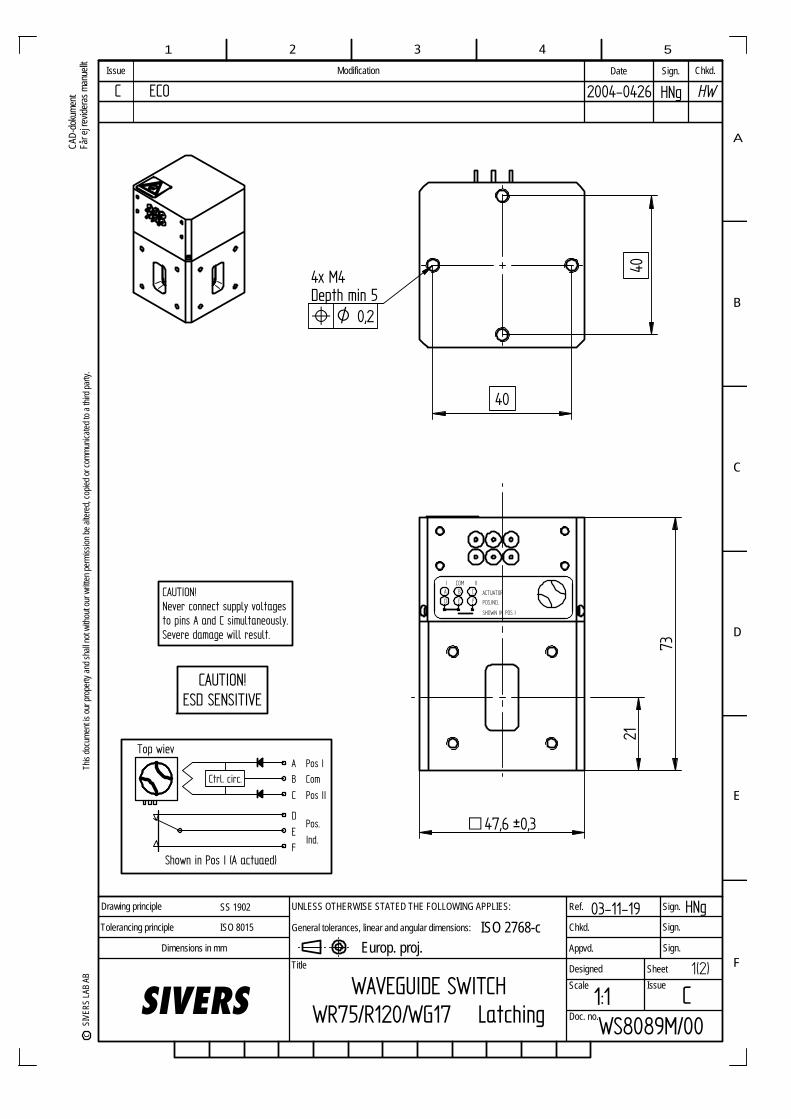
1(2)
40
40
POS.IND.
CB
FED
A ACTUATOR
COMI II
SHOWN IN POS I
F
E
D
C
B
A
1 2 3 4 5
Ref.
Chkd.
Appvd.
Designed
Sign.
Sign.
Sign.
Sheet Scale Issue
Doc. no.SIVERS
Dimensions in mm Title
Europ. proj.
UNLESS OTHERWISE STATED THE FOLLOWING APPLIES:
General tolerances, linear and angular dimensions: ISO 2768-c Drawing principle
Tolerancing principle
SS 1902
ISO 8015
This
docu
ment
is ou
r pro
perty
and s
hall n
ot wi
thout
our w
ritten
perm
ission
be al
tered
, cop
ied or
comm
unica
ted to
a thi
rd pa
rty.
c
SIVE
RS LA
B AB
CAD-
doku
ment
Får e
j revid
eras
man
uellt Modification Date Sign.Issue Chkd.
WS8089M/001:1 C
03-11-19 HNg
WAVEGUIDE SWITCHWR75/R120/WG17 Latching
47,6 ±0,3q
CAUTION!ESD SENSITIVE
Ctrl. circ.
Top wievAB
C
D
EF
Pos I
Pos II
Com
Pos.
Ind.
Shown in Pos I (A actuaed)
CAUTION!Never connect supply voltagesto pins A and C simultaneously.Severe damage will result.
4x M4Depth min 5l O 0,2
21
73
C ECO 2004-0426 HNg HW SIVERS Reference Approved Origin date Issue date Issue Page Document HNg HW 1996-02-12 2004-04-26 C 2 (2) WS 8089M/00 ___________________________________________________________________________________________________
RF DATA
Frequency range 10 – 15 GHz VSWR 1.08 Insertion loss 0.1 dB Isolation 60 dB Peak power 200 kW at 0.1 MPa abs., +25°C Average power 3 kW Flange interface MIL-DTL-3922/70B-005
Modified with 6-32 UNC-2B, thread depth min 5
ACTUATOR DATA
Operating voltage 28±3 VDC Operating current 1 A, Self cut off Switching time 150 ms Duty (min time between 500 ms -40°C to +40°C linearly successive operations) increasing to 2 s at +85°C Connector Soldering pins
POSITION INDICATOR
Position indicator current 60 V Max, 50 mA Max Resistive load
MECHANICAL DATA
Material Aluminium alloy, Cu free Finishing Chromate per MIL-C-5541 and black painted Air pressure 0.1 MPa overpressure Air leakage 10 cm3/min. (0.1 MPa overpr.) Max Weight 0.35 kg Max Life 250 000 actuations
ENVIRONMENTAL DATA
Ambient temperature -40°C to +85°C Vibration 5 – 18 Hz, 3 mm amplitude 18 – 2000 Hz, 15 g Humidity 100%RH if dry air in waveguide ___________________________________________________________________________________ This document must not be copied without our written permission, and the contents thereof must not be imparted to a third party nor be used for any unauthorized purpose. © Sivers Lab AB, Sweden WS 8089M/00
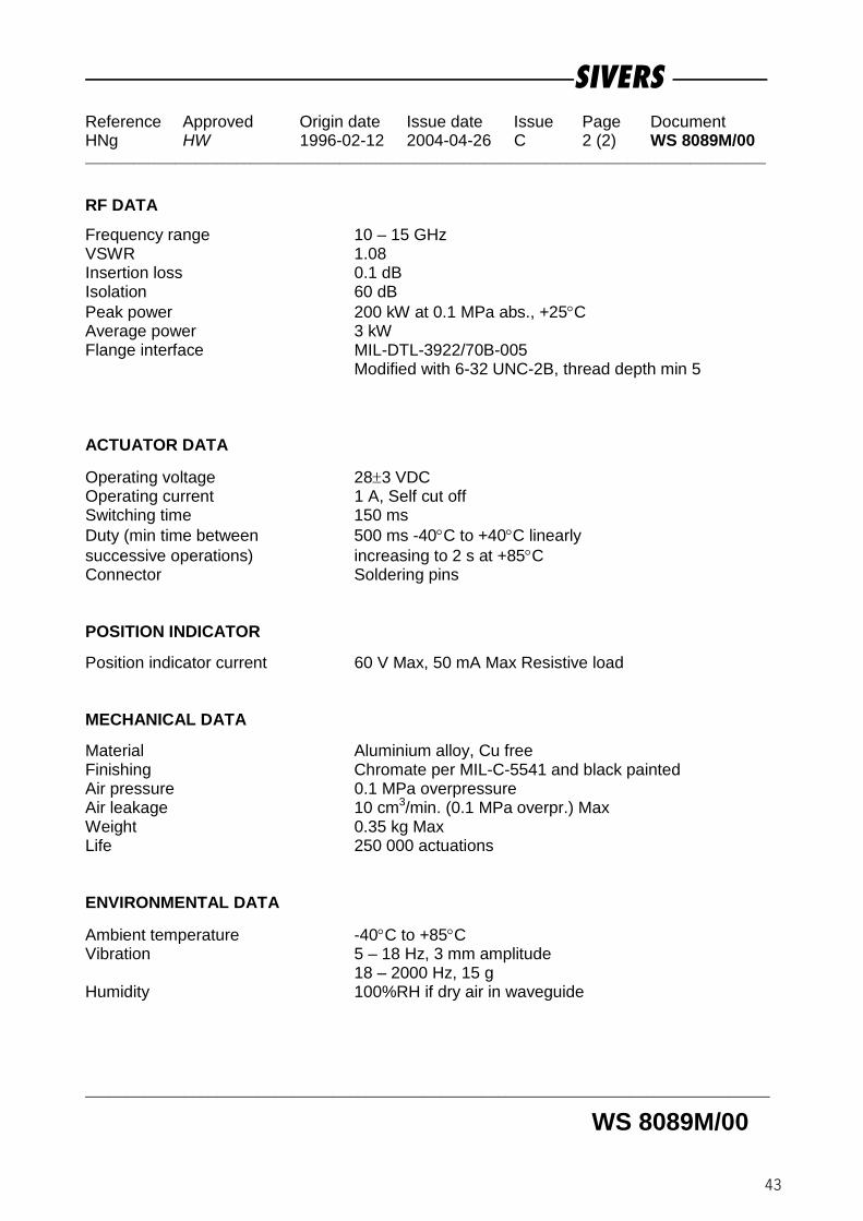
43
SIVERS Reference Approved Origin date Issue date Issue Page Document HNg HW 1996-02-12 2004-04-26 C 2 (2) WS 8089M/00 ___________________________________________________________________________________________________
RF DATA
Frequency range 10 – 15 GHz VSWR 1.08 Insertion loss 0.1 dB Isolation 60 dB Peak power 200 kW at 0.1 MPa abs., +25°C Average power 3 kW Flange interface MIL-DTL-3922/70B-005
Modified with 6-32 UNC-2B, thread depth min 5
ACTUATOR DATA
Operating voltage 28±3 VDC Operating current 1 A, Self cut off Switching time 150 ms Duty (min time between 500 ms -40°C to +40°C linearly successive operations) increasing to 2 s at +85°C Connector Soldering pins
POSITION INDICATOR
Position indicator current 60 V Max, 50 mA Max Resistive load
MECHANICAL DATA
Material Aluminium alloy, Cu free Finishing Chromate per MIL-C-5541 and black painted Air pressure 0.1 MPa overpressure Air leakage 10 cm3/min. (0.1 MPa overpr.) Max Weight 0.35 kg Max Life 250 000 actuations
ENVIRONMENTAL DATA
Ambient temperature -40°C to +85°C Vibration 5 – 18 Hz, 3 mm amplitude 18 – 2000 Hz, 15 g Humidity 100%RH if dry air in waveguide ___________________________________________________________________________________ This document must not be copied without our written permission, and the contents thereof must not be imparted to a third party nor be used for any unauthorized purpose. © Sivers Lab AB, Sweden WS 8089M/00

F
E
D
C
B
A
1 2 3 4 5
Ref.
Chkd.
Appvd.
Designed
Sign.
Sign.
Sign.
Sheet Scale Issue
Doc. noSIVERS
Dimensions in mm Title
Europ. proj.
UNLESS OTHERWISE STATED THE FOLLOWING APPLIES:
General tolerances, linear and angular dimensions: ISO 2768-c Drawing principle
Tolerancing principle
SS 1902
ISO 8015
This
docu
ment
is ou
r pro
perty
and s
hall n
ot wi
thout
our w
ritten
perm
ission
be al
tered
, cop
ied or
comm
unica
ted to
a thi
rd pa
rty.
c
SIVE
RS LA
B AB
CAD-
doku
ment
Får e
j revid
eras
man
uellt Modification Date Sign.Issue Chkd.
WAVEGUIDE SWITCHWR75/R120/WG17 Latching WS 8189M/00
2003-1117
1:1,5 F
HNg
40
40
47,6q
4x M4Depth min 5
21
102
94
118
l O 0,2
Ctrl. circ.
Top wievAB
C
D
EF
Pos I
Pos II
Com
Shown in Pos I (A actuaed)
GHJ
KLM
NP
Pos.Ind. 1
Pos.Ind. 2
Pos.Ind. 3
INHIBITOpened during VSWR >1,2
MANUAL OVERRIDE
CAUTION!ESD SENSITIVE
CAUTION!ESD SENSITIVE
1 (2)HW
SIVERS Reference Approved Origin date Issue date Issue Page Document HNg HW 1999-06-17 2003-11-17 F 2 (2) WS 8189M/00 ___________________________________________________________________________________________________
RF DATA
Frequency range 10 – 15 GHz VSWR 1.08 Insertion loss 0.1 dB Isolation 70 dB Peak power 250 kW at 0.1 MPa abs., +25°C Average power 2 kW Flange interface MIL-DTL-3922/70B-005
Modified with 6-32 UNC-2B, thread depth min 5
ACTUATOR DATA
Operating voltage 28±3 V DC Operating current 1 A, Self cut off Switching time 100 ms Duty (min time between 500 ms -20°C to +40°C successive operations) linearly increasing to 2 s at +70°C Connector MS 3112E 14-19P Mating connector MS 3116F 14-19S or eq.
POSITION INDICATOR
Voltage / Current 30 V Max, 100 mA Max Resistive load Position indicator Three sets of C-form contacts and one set of inhibit contact, opened during VSWR >1.2
MECHANICAL DATA
Material Aluminium alloy, Cu free Finishing Chromate per MIL-C-5541 and black painted Air pressure 0.1 MPa overpr. Max Air leakage 10 cm3/min (0.1 MPa overpr.) Max Weight 0.45 kg Max Life 250 000 actuations
ENVIRONMENTAL DATA
Ambient temperature -20°C to +70°C Vibration 5 – 18 Hz, 3 mm amplitude 18 – 2000 Hz, 15 g Humidity 100%RH if dry air in waveguide ___________________________________________________________________________________ This document must not be copied without our written permission, and the contents thereof must not be imparted to a third party nor be used for any unauthorized purpose. © Sivers Lab AB, Sweden WS 8189M/00

45
SIVERS Reference Approved Origin date Issue date Issue Page Document HNg HW 1999-06-17 2003-11-17 F 2 (2) WS 8189M/00 ___________________________________________________________________________________________________
RF DATA
Frequency range 10 – 15 GHz VSWR 1.08 Insertion loss 0.1 dB Isolation 70 dB Peak power 250 kW at 0.1 MPa abs., +25°C Average power 2 kW Flange interface MIL-DTL-3922/70B-005
Modified with 6-32 UNC-2B, thread depth min 5
ACTUATOR DATA
Operating voltage 28±3 V DC Operating current 1 A, Self cut off Switching time 100 ms Duty (min time between 500 ms -20°C to +40°C successive operations) linearly increasing to 2 s at +70°C Connector MS 3112E 14-19P Mating connector MS 3116F 14-19S or eq.
POSITION INDICATOR
Voltage / Current 30 V Max, 100 mA Max Resistive load Position indicator Three sets of C-form contacts and one set of inhibit contact, opened during VSWR >1.2
MECHANICAL DATA
Material Aluminium alloy, Cu free Finishing Chromate per MIL-C-5541 and black painted Air pressure 0.1 MPa overpr. Max Air leakage 10 cm3/min (0.1 MPa overpr.) Max Weight 0.45 kg Max Life 250 000 actuations
ENVIRONMENTAL DATA
Ambient temperature -20°C to +70°C Vibration 5 – 18 Hz, 3 mm amplitude 18 – 2000 Hz, 15 g Humidity 100%RH if dry air in waveguide ___________________________________________________________________________________ This document must not be copied without our written permission, and the contents thereof must not be imparted to a third party nor be used for any unauthorized purpose. © Sivers Lab AB, Sweden WS 8189M/00

1 (2) F
E
D
C
B
A
1 2 3 4 5
Ref.
Chkd.
Appvd.
Designed
Sign.
Sign.
Sign.
Sheet Scale Issue
Doc. no.SIVERS
Dimensions in mm Title
Europ. proj.
UNLESS OTHERWISE STATED THE FOLLOWING APPLIES:
General tolerances, linear and angular dimensions: ISO 2768-c Drawing principle
Tolerancing principle
SS 1902
ISO 8015
This
docu
ment
is ou
r pro
perty
and s
hall n
ot wi
thout
our w
ritten
perm
ission
be al
tered
, cop
ied or
comm
unica
ted to
a thi
rd pa
rty.
c
SIVE
RS LA
B AB
CAD-
doku
ment
Får e
j revid
eras
man
uellt Modification Date Sign.Issue Chkd.
030317 CEl
C1:1,5WS8189M/70
HWHW
B Coax connectors twisted 45° 030710 MTr
WAVEGUIDE SWITCHWR75/R120/WG17 Latching
with COAX DPDT
C ECO 2003-1015 HNg
15,56q
47,6
47,6
O 40
2021
102
94
118
Ctrl. circ.
Top wievAB
C
D
EF
Pos I
Pos II
Com
Shown in Pos I (A actuaed)
GHJ
KLM
NP
Pos.Ind. 1
Pos.Ind. 2
Pos.Ind. 3
INHIBITOpened during VSWR >1,2
CAUTION!ESD SENSITIVE
CAUTION!ESD SENSITIVE
HWHW
SIVERS Reference Approved Origin date Issue date Issue Page Document HNg HW 2003-03-17 2003-11-05 C 2 (2) WS 8189M/70 ___________________________________________________________________________________________________
RF DATA Waveguide Frequency range 10 – 15 GHz VSWR 1.08 Insertion loss 0.1 dB Isolation 70 dB Peak power 250 kW at 0.1 MPa abs., +25°C Average power 2 kW Flange interface MIL-DTL-3922/70B-005
Modified with 6 – 32 UNC-2B, thread depth min 6 Coax Frequency range 10 – 15 GHz VSWR 1.5 Insertion loss 0.5 dB Isolation 50 dB Peak power 5 kW Average power 15 W max Coax connector SMA-female
Isolation, waveguide-coax 120 dB ACTUATOR DATA Operating voltage 28±3 V DC Operating current 1 A, Self cut off Switching time 100 ms Connector MS 3112E 14-19P Mating connector MS 3116F 14-19S or eq. POSITION INDICATOR Voltage / Current 30 V Max, 100 mA Max Resistive load Position indicator Tree sets of C-form contacts and one set of
inhibit contact, opened during VSWR >1.2 MECHANICAL DATA Material Aluminium alloy; Cu-free Finishing Chromate per MIL-C-5541 Air pressure 0.1 MPa overpr. Max Air leakage 10 cm3/min (0.1 MPa overpr.) Max Weight 0.6 kg Max Life 250 000 actuations ENVIRONMENTAL DATA
Ambient temperature -20°C to +70°C Vibration 5 – 18 Hz, 3 mm amplitude 18 – 2000 Hz, 15 g Humidity 100%RH if dry air in waveguide __________________________________________________________________________________This document must not be copied without our written permission, and the contents thereof must not be imparted to a third party nor be used for any unauthorized purpose. © Sivers Lab AB, Sweden WS 8189M/70

47
SIVERS Reference Approved Origin date Issue date Issue Page Document HNg HW 2003-03-17 2003-11-05 C 2 (2) WS 8189M/70 ___________________________________________________________________________________________________
RF DATA Waveguide Frequency range 10 – 15 GHz VSWR 1.08 Insertion loss 0.1 dB Isolation 70 dB Peak power 250 kW at 0.1 MPa abs., +25°C Average power 2 kW Flange interface MIL-DTL-3922/70B-005
Modified with 6 – 32 UNC-2B, thread depth min 6 Coax Frequency range 10 – 15 GHz VSWR 1.5 Insertion loss 0.5 dB Isolation 50 dB Peak power 5 kW Average power 15 W max Coax connector SMA-female
Isolation, waveguide-coax 120 dB ACTUATOR DATA Operating voltage 28±3 V DC Operating current 1 A, Self cut off Switching time 100 ms Connector MS 3112E 14-19P Mating connector MS 3116F 14-19S or eq. POSITION INDICATOR Voltage / Current 30 V Max, 100 mA Max Resistive load Position indicator Tree sets of C-form contacts and one set of
inhibit contact, opened during VSWR >1.2 MECHANICAL DATA Material Aluminium alloy; Cu-free Finishing Chromate per MIL-C-5541 Air pressure 0.1 MPa overpr. Max Air leakage 10 cm3/min (0.1 MPa overpr.) Max Weight 0.6 kg Max Life 250 000 actuations ENVIRONMENTAL DATA
Ambient temperature -20°C to +70°C Vibration 5 – 18 Hz, 3 mm amplitude 18 – 2000 Hz, 15 g Humidity 100%RH if dry air in waveguide __________________________________________________________________________________This document must not be copied without our written permission, and the contents thereof must not be imparted to a third party nor be used for any unauthorized purpose. © Sivers Lab AB, Sweden WS 8189M/70

1 (2)
57,15
F
E
D
C
B
A
1 2 3 4 5
Ref.
Chkd.
Appvd.
Designed
Sign.
Sign.
Sign.
Sheet Scale Issue
Doc. no.SIVERS
Dimensions in mm Title
Europ. proj.
UNLESS OTHERWISE STATED THE FOLLOWING APPLIES:
General tolerances, linear and angular dimensions: ISO 2768-c Drawing principle
Tolerancing principle
SS 1902
ISO 8015
This
docu
ment
is ou
r pro
perty
and s
hall n
ot wi
thout
our w
ritten
perm
ission
be al
tered
, cop
ied or
comm
unica
ted to
a thi
rd pa
rty.
c
SIVE
RS LA
B AB
CAD-
doku
ment
Får e
j revid
eras
man
uellt Modification Date Sign.Issue Chkd.
020107 CEl
1:1,5 CWS8086P/00
43
B ECO 2003-1016 HNg
Ctrl. circ.
Top viewAB
C
D
EF
Pos I
Pos II
Com
Pos.
Ind.
Shown in Pos I (A actuated)
CAUTION!ESD SENSITIVE
43 57,15
25,5
71,4
92
NAME LABEL
4x M4Depth min 5l O 0,2
WAVEGUIDE SWITCHWR62/R140/WG18 Latching
C ECO 2004-0205 HNgHWHW
HW5/2-04
SIVERS Reference Approved Origin date Issue date Issue Page Document HNg HW 2002-01-07 2004-02-05 C 2 (2) WS 8086P/00 ___________________________________________________________________________________________________
RF DATA
Frequency range 12.4 – 18.0 GHz VSWR 1.08 Insertion loss 0.1 dB Isolation 90 dB Peak power 125 kW at 0.1 MPa abs., +25°C Average power 2 kW Waveguide size WR62 / R140 / WG18 Hole dimensions according to MIL-DTL-3922/53D-018 (6-32 UNC-2B)
thread depth min 5
ACTUATOR DATA
Operating voltage 28±3 V DC Operating current 1 A, Self cut off Switching time 300 ms Duty (min time between 500 ms -40°C to +40°C successive operations) linearly increasing to 2 s at +85°C Connector MS 3112E 10-6P Mating connector MS 3116F 10-6S or eq.
POSITION INDICATOR
Voltage / Current 30 V Max, 100 mA Max Resistive load
MECHANICAL DATA
Material Aluminium alloy, Cu free Finishing Chromate per MIL-C-5541 and black painted Air pressure 0.1 MPa overpr. Max Air leakage 10 cm3/min (0.1 MPa overpr.) Max Weight 0,5 kg Max Life 250 000 actuations
ENVIRONMENTAL DATA
Ambient temperature -40°C to +85°C Vibration 5 – 18 Hz, 3 mm amplitude 18 – 2000 Hz, 15 g Humidity 100%RH if dry air in waveguide ___________________________________________________________________________________ This document must not be copied without our written permission, and the contents thereof must not be imparted to a third party nor be used for any unauthorized purpose. © Sivers Lab AB, Sweden WS 8086P/00

49
SIVERS Reference Approved Origin date Issue date Issue Page Document HNg HW 2002-01-07 2004-02-05 C 2 (2) WS 8086P/00 ___________________________________________________________________________________________________
RF DATA
Frequency range 12.4 – 18.0 GHz VSWR 1.08 Insertion loss 0.1 dB Isolation 90 dB Peak power 125 kW at 0.1 MPa abs., +25°C Average power 2 kW Waveguide size WR62 / R140 / WG18 Hole dimensions according to MIL-DTL-3922/53D-018 (6-32 UNC-2B)
thread depth min 5
ACTUATOR DATA
Operating voltage 28±3 V DC Operating current 1 A, Self cut off Switching time 300 ms Duty (min time between 500 ms -40°C to +40°C successive operations) linearly increasing to 2 s at +85°C Connector MS 3112E 10-6P Mating connector MS 3116F 10-6S or eq.
POSITION INDICATOR
Voltage / Current 30 V Max, 100 mA Max Resistive load
MECHANICAL DATA
Material Aluminium alloy, Cu free Finishing Chromate per MIL-C-5541 and black painted Air pressure 0.1 MPa overpr. Max Air leakage 10 cm3/min (0.1 MPa overpr.) Max Weight 0,5 kg Max Life 250 000 actuations
ENVIRONMENTAL DATA
Ambient temperature -40°C to +85°C Vibration 5 – 18 Hz, 3 mm amplitude 18 – 2000 Hz, 15 g Humidity 100%RH if dry air in waveguide ___________________________________________________________________________________ This document must not be copied without our written permission, and the contents thereof must not be imparted to a third party nor be used for any unauthorized purpose. © Sivers Lab AB, Sweden WS 8086P/00

1 (2)
57,15
F
E
D
C
B
A
1 2 3 4 5
Ref.
Chkd.
Appvd.
Designed
Sign.
Sign.
Sign.
Sheet Scale Issue
Doc. no.SIVERS
Dimensions in mm Title
Europ. proj.
UNLESS OTHERWISE STATED THE FOLLOWING APPLIES:
General tolerances, linear and angular dimensions: ISO 2768-c Drawing principle
Tolerancing principle
SS 1902
ISO 8015
This
docu
ment
is ou
r pro
perty
and s
hall n
ot wi
thout
our w
ritten
perm
ission
be al
tered
, cop
ied or
comm
unica
ted to
a thi
rd pa
rty.
c
SIVE
RS LA
B AB
CAD-
doku
ment
Får e
j revid
eras
man
uellt Modification Date Sign.Issue Chkd.
030214 CEl
1:1,5 B
WS8087P/00
43
HWHW
WAVEGUIDE SWITCHWR62/R140/WG18 Fail-safe
B ECO 2003-1016 HNg
CAUTION!ESD SENSITIVE
43 57,15
4x M4Depth min 5
25,5
71,4
92
Ctrl. circ.
Top wiev
C
B
A
F
E
D
NC
Pos II
Com
Pos.
Ind.
Shown in de-energized position
R
NAME LABEL
HW
SIVERS Reference Approved Origin date Issue date Issue Page Document HNg HW 2003-02-14 2003-11-04 B 2 (2) WS 8087P/00 ___________________________________________________________________________________________________
RF DATA
Frequency range 12.4 – 18.0 GHz VSWR 1.08 Insertion loss 0.1 dB Isolation 90 dB Peak power 125 kW at 0.1 MPa abs., +25°C Average power 2 kW Flange interface MIL-DTL-3922/53D-005
Modified with 6-32 UNC-2B, thread depth min 5
ACTUATOR DATA
Operating voltage 28±3 V DC Operating current 1 A, Auto switch on to holding current after 200 ms Holding current 300 mA Switching time 300 ms Duty (min time between 500 ms -40°C to +40°C successive operations) linearly increasing to 2 s at +85°C Connector MS 3112E 10-6P Mating connector MS 3116F 10-6S or eq.
POSITION INDICATOR
Voltage / Current 30 V Max, 100 mA Max Resistive load
MECHANICAL DATA
Material Aluminium alloy, Cu free Finishing Chromate per MIL-C-5541 and black painted Air pressure 0.1 MPa overpr. Max Air leakage 10 cm3/min (0.1 MPa overpr.) Max Weight 0.5 kg Max Life 250 000 actuations
ENVIRONMENTAL DATA
Ambient temperature -40°C to +85°C Vibration 5 – 18 Hz, 3 mm amplitude 18 – 2000 Hz, 15 g Humidity 100%RH if dry air in waveguide _____________________________________________________________________________________This document must not be copied without our written permission, and the contents thereof must not be imparted to a third party nor be used for any unauthorized purpose. © Sivers Lab AB, Sweden WS 8087P/00

51
SIVERS Reference Approved Origin date Issue date Issue Page Document HNg HW 2003-02-14 2003-11-04 B 2 (2) WS 8087P/00 ___________________________________________________________________________________________________
RF DATA
Frequency range 12.4 – 18.0 GHz VSWR 1.08 Insertion loss 0.1 dB Isolation 90 dB Peak power 125 kW at 0.1 MPa abs., +25°C Average power 2 kW Flange interface MIL-DTL-3922/53D-005
Modified with 6-32 UNC-2B, thread depth min 5
ACTUATOR DATA
Operating voltage 28±3 V DC Operating current 1 A, Auto switch on to holding current after 200 ms Holding current 300 mA Switching time 300 ms Duty (min time between 500 ms -40°C to +40°C successive operations) linearly increasing to 2 s at +85°C Connector MS 3112E 10-6P Mating connector MS 3116F 10-6S or eq.
POSITION INDICATOR
Voltage / Current 30 V Max, 100 mA Max Resistive load
MECHANICAL DATA
Material Aluminium alloy, Cu free Finishing Chromate per MIL-C-5541 and black painted Air pressure 0.1 MPa overpr. Max Air leakage 10 cm3/min (0.1 MPa overpr.) Max Weight 0.5 kg Max Life 250 000 actuations
ENVIRONMENTAL DATA
Ambient temperature -40°C to +85°C Vibration 5 – 18 Hz, 3 mm amplitude 18 – 2000 Hz, 15 g Humidity 100%RH if dry air in waveguide _____________________________________________________________________________________This document must not be copied without our written permission, and the contents thereof must not be imparted to a third party nor be used for any unauthorized purpose. © Sivers Lab AB, Sweden WS 8087P/00

1(2)
40
40
POS.IND.
CB
FEDACTUATOR
COM II
SHOWN DE-ENERGIZED
F
E
D
C
B
A
1 2 3 4 5
Ref.
Chkd.
Appvd.
Designed
Sign.
Sign.
Sign.
Sheet Scale Issue
Doc. no.SIVERS
Dimensions in mm Title
Europ. proj.
UNLESS OTHERWISE STATED THE FOLLOWING APPLIES:
General tolerances, linear and angular dimensions: ISO 2768-c Drawing principle
Tolerancing principle
SS 1902
ISO 8015
This
docu
ment
is ou
r pro
perty
and s
hall n
ot wi
thout
our w
ritten
perm
ission
be al
tered
, cop
ied or
comm
unica
ted to
a thi
rd pa
rty.
c
SIVE
RS LA
B AB
CAD-
doku
ment
Får e
j revid
eras
man
uellt Modification Date Sign.Issue Chkd.
WS8088P/001:1 C
03-11-19 HNg
WAVEGUIDE SWITCHWR62/R140/WG18 Fail-safe
47,6 ±0,3q
CAUTION!ESD SENSITIVE
4x M4Depth min 5l O 0,2
21
73
Ctrl. circ.
Top wiev
C
B
A
F
E
D
NC
Pos II
Com
Pos.Ind.
Shown in de-energized position
R
C ECO 2004-0426 HNg HW SIVERS Reference Approved Origin date Issue date Issue Page Document HNg HW 1997-12-17 2004-04-26 C 2 (2) WS 8088P/00 ___________________________________________________________________________________________________
RF DATA
Frequency range 12.4 – 18.0 GHz VSWR 1.08 Insertion loss 0.1 dB Isolation 60 dB Peak power 125 kW at 0.1 MPa abs., +25°C Average power 2 kW Flange interface MIL-DTL-3922/53D-018
Modified with 6-32 UNC-2B, thread depth min 5
ACTUATOR DATA
Operating voltage 28±3 VDC Operating current 1A, Self cut off Holding current 0.3 A Switching time 150 ms Duty (min time between 500 ms -40°C to +40°C successive operations) linearly increasing to 2 s at +85°C Connector Soldering pins
POSITION INDICATOR
Position indicator current 60 V Max, 50 mA Max Resistive load
MECHANICAL DATA
Material Aluminium alloy, Cu free Finishing Chromate per MIL-C-5541 and black painted Air pressure 0.1 MPa overpressure Max Air leakage 10 cm3/min. (0.1 MPa overpr.) Max Weight 0.35 kg Max Life 250 000 actuations
ENVIRONMENTAL DATA
Ambient temperature -40°C to +85°C Vibration 5 – 18 Hz, 3 mm amplitude 18 – 2000 Hz, 15 g Humidity 100%RH if dry air in waveguide ___________________________________________________________________________________ This document must not be copied without our written permission, and the contents thereof must not be imparted to a third party nor be used for any unauthorized purpose. © Sivers Lab AB, Sweden WS 8088P/00

53
SIVERS Reference Approved Origin date Issue date Issue Page Document HNg HW 1997-12-17 2004-04-26 C 2 (2) WS 8088P/00 ___________________________________________________________________________________________________
RF DATA
Frequency range 12.4 – 18.0 GHz VSWR 1.08 Insertion loss 0.1 dB Isolation 60 dB Peak power 125 kW at 0.1 MPa abs., +25°C Average power 2 kW Flange interface MIL-DTL-3922/53D-018
Modified with 6-32 UNC-2B, thread depth min 5
ACTUATOR DATA
Operating voltage 28±3 VDC Operating current 1A, Self cut off Holding current 0.3 A Switching time 150 ms Duty (min time between 500 ms -40°C to +40°C successive operations) linearly increasing to 2 s at +85°C Connector Soldering pins
POSITION INDICATOR
Position indicator current 60 V Max, 50 mA Max Resistive load
MECHANICAL DATA
Material Aluminium alloy, Cu free Finishing Chromate per MIL-C-5541 and black painted Air pressure 0.1 MPa overpressure Max Air leakage 10 cm3/min. (0.1 MPa overpr.) Max Weight 0.35 kg Max Life 250 000 actuations
ENVIRONMENTAL DATA
Ambient temperature -40°C to +85°C Vibration 5 – 18 Hz, 3 mm amplitude 18 – 2000 Hz, 15 g Humidity 100%RH if dry air in waveguide ___________________________________________________________________________________ This document must not be copied without our written permission, and the contents thereof must not be imparted to a third party nor be used for any unauthorized purpose. © Sivers Lab AB, Sweden WS 8088P/00

1(2)
40
40
POS.IND.
CB
FED
A ACTUATOR
COMI II
SHOWN IN POS I
F
E
D
C
B
A
1 2 3 4 5
Ref.
Chkd.
Appvd.
Designed
Sign.
Sign.
Sign.
Sheet Scale Issue
Doc. no.SIVERS
Dimensions in mm Title
Europ. proj.
UNLESS OTHERWISE STATED THE FOLLOWING APPLIES:
General tolerances, linear and angular dimensions: ISO 2768-c Drawing principle
Tolerancing principle
SS 1902
ISO 8015
This
docu
ment
is ou
r pro
perty
and s
hall n
ot wi
thout
our w
ritten
perm
ission
be al
tered
, cop
ied or
comm
unica
ted to
a thi
rd pa
rty.
c
SIVE
RS LA
B AB
CAD-
doku
ment
Får e
j revid
eras
man
uellt Modification Date Sign.Issue Chkd.
WS8089P/001:1 C
03-11-19 HNg
WAVEGUIDE SWITCHWR62/R140/WG18 Latching
47,6 ±0,3q
CAUTION!ESD SENSITIVE
Ctrl. circ.
Top wievAB
C
D
EF
Pos I
Pos II
Com
Pos.
Ind.
Shown in Pos I (A actuaed)
CAUTION!Never connect supply voltagesto pins A and C simultaneously.Severe damage will result.
4x M4Depth min 5l O 0,2
21
73
C ECO 2004-0426 HNg HW
SIVERS Reference Approved Origin date Issue date Issue Page Document HNg HW 1997-12-16 2004-04-26 C 2 (2) WS 8089P/00 ___________________________________________________________________________________________________
RF DATA
Frequency range 12.4 – 18.0 GHz VSWR 1.08 Insertion loss 0.1 dB Isolation 60 dB Peak power 125 kW at 0.1 MPa abs., +25°C Average power 2 kW Flange interface MIL-DTL-3922/53D-018
Modified with6-32 UNC-2B, thread depth min 5
ACTUATOR DATA
Operating voltage 28±3 VDC Operating current 1 A, Self cut off Switching time 150 ms Duty (min time between 500 ms -40°C to +40°C linearly successive operations) increasing to 2 s at +85°C Connector Soldering pins
POSITION INDICATOR
Position indicator current 60 V Max, 50 mA Max Resistive load
MECHANICAL DATA
Material Aluminium alloy, Cu free Finishing Chromate per MIL-C-5541 and black painted Air pressure 0.1 MPa overpressure Max Air leakage 10 cm3/min. (0.1 MPa overpr.) Max Weight 0.35 kg Max Life 250 000 actuations
ENVIRONMENTAL DATA
Ambient temperature -40°C to +85°C Vibration 5 – 18 Hz, 3 mm amplitude 18 – 2000 Hz, 15 g Humidity 100%RH if dry air in waveguide ___________________________________________________________________________________ This document must not be copied without our written permission, and the contents thereof must not be imparted to a third party nor be used for any unauthorized purpose. © Sivers Lab AB, Sweden WS 8089P/00

55
SIVERS Reference Approved Origin date Issue date Issue Page Document HNg HW 1997-12-16 2004-04-26 C 2 (2) WS 8089P/00 ___________________________________________________________________________________________________
RF DATA
Frequency range 12.4 – 18.0 GHz VSWR 1.08 Insertion loss 0.1 dB Isolation 60 dB Peak power 125 kW at 0.1 MPa abs., +25°C Average power 2 kW Flange interface MIL-DTL-3922/53D-018
Modified with6-32 UNC-2B, thread depth min 5
ACTUATOR DATA
Operating voltage 28±3 VDC Operating current 1 A, Self cut off Switching time 150 ms Duty (min time between 500 ms -40°C to +40°C linearly successive operations) increasing to 2 s at +85°C Connector Soldering pins
POSITION INDICATOR
Position indicator current 60 V Max, 50 mA Max Resistive load
MECHANICAL DATA
Material Aluminium alloy, Cu free Finishing Chromate per MIL-C-5541 and black painted Air pressure 0.1 MPa overpressure Max Air leakage 10 cm3/min. (0.1 MPa overpr.) Max Weight 0.35 kg Max Life 250 000 actuations
ENVIRONMENTAL DATA
Ambient temperature -40°C to +85°C Vibration 5 – 18 Hz, 3 mm amplitude 18 – 2000 Hz, 15 g Humidity 100%RH if dry air in waveguide ___________________________________________________________________________________ This document must not be copied without our written permission, and the contents thereof must not be imparted to a third party nor be used for any unauthorized purpose. © Sivers Lab AB, Sweden WS 8089P/00

F
E
D
C
B
A
1 2 3 4 5
Ref.
Chkd.
Appvd.
Designed
Sign.
Sign.
Sign.
Sheet Scale Issue
Doc. noSIVERS
Dimensions in mm Title
Europ. proj.
UNLESS OTHERWISE STATED THE FOLLOWING APPLIES:
General tolerances, linear and angular dimensions: ISO 2768-c Drawing principle
Tolerancing principle
SS 1902
ISO 8015
This
docu
ment
is ou
r pro
perty
and s
hall n
ot wi
thout
our w
ritten
perm
ission
be al
tered
, cop
ied or
comm
unica
ted to
a thi
rd pa
rty.
c
SIVE
RS LA
B AB
CAD-
doku
ment
Får e
j revid
eras
man
uellt Modification Date Sign.Issue Chkd.
WAVEGUIDE SWITCHWR62/R140/WG18 Latching WS 8189P/00
2004-0426
1:1,5 F
HNg
40
40
47,6q
4x M4Depth min 5
21
102
94
118
l O 0,2
Ctrl. circ.
Top wievAB
C
D
EF
Pos I
Pos II
Com
Shown in Pos I (A actuaed)
GHJ
KLM
NP
Pos.Ind. 1
Pos.Ind. 2
Pos.Ind. 3
INHIBITOpened during VSWR >1,2
MANUAL OVERRIDE
CAUTION!ESD SENSITIVE
CAUTION!ESD SENSITIVE
1 (2)
F ECO 2004-0426 HNg HW
SIVERS Reference Approved Origin date Issue date Issue Page Document HNg HW 1997-10-16 2004-04-26 F 2 (2) WS 8189P/00 ___________________________________________________________________________________________________
RF DATA
Frequency range 12.4 – 18.0 GHz VSWR 1.05 Insertion loss 0.1 dB Isolation 60 dB Peak power 125 kW at 0.1 MPa abs., +25°C Average power 2 kW Flange interface MIL-DTL-3922/53D-018
Modified with 6-32 UNC-2B, thread depth min 5
ACTUATOR DATA
Operating voltage 28±3 VDC Operating current 1 A, Self cut off Switching time 100 ms Duty (min time between 500 ms -20°C to +40°C linearly successive operations) increasing to 2 s at +70°C Connector MS 3112E 14-19P Mating connector MS 3116F 14-19S or eq.
POSITION INDICATOR
Voltage / Current 30 V Max, 100 mA Max Resistive load Position indicator Three sets of C-form contacts and one set of inhibit contact, opened during VSWR >1.2
MECHANICAL DATA
Material Aluminium alloy, Cu free Finishing Chromate per MIL-C-5541 and black painted Air pressure 0.1 MPa overpr. Max Air leakage 10 cm3/min (0.1 MPa overpr.) Max Weight 0.45 kg Max Life 250 000 actuations
ENVIRONMENTAL DATA
Ambient temperature -20°C to +70°C Vibration 5 – 18 Hz, 3 mm amplitude 18 – 2000 Hz, 15 g Humidity 100%RH if dry air in waveguide ___________________________________________________________________________________ This document must not be copied without our written permission, and the contents thereof must not be imparted to a third party nor be used for any unauthorized purpose. © Sivers Lab AB, Sweden WS 8189P/00

57
SIVERS Reference Approved Origin date Issue date Issue Page Document HNg HW 1997-10-16 2004-04-26 F 2 (2) WS 8189P/00 ___________________________________________________________________________________________________
RF DATA
Frequency range 12.4 – 18.0 GHz VSWR 1.05 Insertion loss 0.1 dB Isolation 60 dB Peak power 125 kW at 0.1 MPa abs., +25°C Average power 2 kW Flange interface MIL-DTL-3922/53D-018
Modified with 6-32 UNC-2B, thread depth min 5
ACTUATOR DATA
Operating voltage 28±3 VDC Operating current 1 A, Self cut off Switching time 100 ms Duty (min time between 500 ms -20°C to +40°C linearly successive operations) increasing to 2 s at +70°C Connector MS 3112E 14-19P Mating connector MS 3116F 14-19S or eq.
POSITION INDICATOR
Voltage / Current 30 V Max, 100 mA Max Resistive load Position indicator Three sets of C-form contacts and one set of inhibit contact, opened during VSWR >1.2
MECHANICAL DATA
Material Aluminium alloy, Cu free Finishing Chromate per MIL-C-5541 and black painted Air pressure 0.1 MPa overpr. Max Air leakage 10 cm3/min (0.1 MPa overpr.) Max Weight 0.45 kg Max Life 250 000 actuations
ENVIRONMENTAL DATA
Ambient temperature -20°C to +70°C Vibration 5 – 18 Hz, 3 mm amplitude 18 – 2000 Hz, 15 g Humidity 100%RH if dry air in waveguide ___________________________________________________________________________________ This document must not be copied without our written permission, and the contents thereof must not be imparted to a third party nor be used for any unauthorized purpose. © Sivers Lab AB, Sweden WS 8189P/00

1 (2) F
E
D
C
B
A
1 2 3 4 5
Ref.
Chkd.
Appvd.
Designed
Sign.
Sign.
Sign.
Sheet Scale Issue
Doc. no.SIVERS
Dimensions in mm Title
Europ. proj.
UNLESS OTHERWISE STATED THE FOLLOWING APPLIES:
General tolerances, linear and angular dimensions: ISO 2768-c Drawing principle
Tolerancing principle
SS 1902
ISO 8015
This
docu
ment
is ou
r pro
perty
and s
hall n
ot wi
thout
our w
ritten
perm
ission
be al
tered
, cop
ied or
comm
unica
ted to
a thi
rd pa
rty.
c
SIVE
RS LA
B AB
CAD-
doku
ment
Får e
j revid
eras
man
uellt Modification Date Sign.Issue Chkd.
021129 CEl
D1:2WS8189P/70
HWHW
C Coax connectors twisted 45° 030710 MTr
WAVEGUIDE SWITCHWR62/R140/WG18 Latching
with COAX DPDT
D Paragraphs added 2003-1015 HNgHWHW
40O
15,56q
47,6
47,6
21
102
20
94
118
MANUAL OVERRIDE
Ctrl. circ.
Top wievAB
C
D
EF
Pos I
Pos II
Com
Shown in Pos I (A actuaed)
GHJ
KLM
NP
Pos.Ind. 1
Pos.Ind. 2
Pos.Ind. 3
INHIBITOpened during VSWR >1,2
CAUTION!ESD SENSITIVE
CAUTION!ESD SENSITIVE
SIVERS Reference Approved Origin date Issue date Issue Page Document HNg HW 2002-11-29 2003-11-05 D 2 (2) WS 8189P/70 ___________________________________________________________________________________________________
RF DATA Waveguide Frequency range 12.4 – 18.0 GHz VSWR 1.05 Insertion loss 0.1 dB Isolation 60 dB Peak power 125 kW at 0.1 MPa abs., +25°C Average power 2 kW Flange interface MIL-DTL-3922/53D-018
Modified with 6 – 32 UNF-2B, thread depth min 6 Coax Frequency range 12.4 – 18.0 GHz VSWR 1.5 Insertion loss 0.5 dB Isolation 40 dB Peak power 5 kW Average power 15 W max Coax connector SMA-female
Isolation, waveguide-coax 120 dB ACTUATOR DATA Operating voltage 28±3 V DC Operating current 1 A, Self cut off Switching time 100 ms Connector MS 3112E 14-19P Mating connector MS 3116F 14-19S or eq. POSITION INDICATOR Voltage / Current 30 V Max, 100 mA Max Resistive load Position indicator Three sets of C-form contacts and one set of
inhibit contact, opened during VSWR >1.2 MECHANICAL DATA Material Aluminium alloy; Cu-free Finishing Chromate per MIL-C-5541 Air pressure 0.1 MPa overpr. Max Air leakage 10 cm3/min (0.1 MPa overpr.) Max Weight 0.6 kg Max Life 250 000 actuations ENVIRONMENTAL DATA
Ambient temperature -20°C to +70°C Vibration 5 – 18 Hz, 3 mm amplitude 18 – 2000 Hz, 15 g Humidity 100%RH if dry air in waveguide __________________________________________________________________________________This document must not be copied without our written permission, and the contents thereof must not be imparted to a third party nor be used for any unauthorized purpose. © Sivers Lab AB, Sweden WS 8189P/70

59
SIVERS Reference Approved Origin date Issue date Issue Page Document HNg HW 2002-11-29 2003-11-05 D 2 (2) WS 8189P/70 ___________________________________________________________________________________________________
RF DATA Waveguide Frequency range 12.4 – 18.0 GHz VSWR 1.05 Insertion loss 0.1 dB Isolation 60 dB Peak power 125 kW at 0.1 MPa abs., +25°C Average power 2 kW Flange interface MIL-DTL-3922/53D-018
Modified with 6 – 32 UNF-2B, thread depth min 6 Coax Frequency range 12.4 – 18.0 GHz VSWR 1.5 Insertion loss 0.5 dB Isolation 40 dB Peak power 5 kW Average power 15 W max Coax connector SMA-female
Isolation, waveguide-coax 120 dB ACTUATOR DATA Operating voltage 28±3 V DC Operating current 1 A, Self cut off Switching time 100 ms Connector MS 3112E 14-19P Mating connector MS 3116F 14-19S or eq. POSITION INDICATOR Voltage / Current 30 V Max, 100 mA Max Resistive load Position indicator Three sets of C-form contacts and one set of
inhibit contact, opened during VSWR >1.2 MECHANICAL DATA Material Aluminium alloy; Cu-free Finishing Chromate per MIL-C-5541 Air pressure 0.1 MPa overpr. Max Air leakage 10 cm3/min (0.1 MPa overpr.) Max Weight 0.6 kg Max Life 250 000 actuations ENVIRONMENTAL DATA
Ambient temperature -20°C to +70°C Vibration 5 – 18 Hz, 3 mm amplitude 18 – 2000 Hz, 15 g Humidity 100%RH if dry air in waveguide __________________________________________________________________________________This document must not be copied without our written permission, and the contents thereof must not be imparted to a third party nor be used for any unauthorized purpose. © Sivers Lab AB, Sweden WS 8189P/70

1(2) F
E
D
C
B
A
1 2 3 4 5
Ref.
Chkd.
Appvd.
Designed
Sign.
Sign.
Sign.
Sheet Scale Issue
Doc. noSIVERS
Dimensions in mm Title
Europ. proj.
UNLESS OTHERWISE STATED THE FOLLOWING APPLIES:
General tolerances, linear and angular dimensions: ISO 2768-c Drawing principle
Tolerancing principle
SS 1902
ISO 8015
This
docu
ment
is ou
r pro
perty
and s
hall n
ot wi
thout
our w
ritten
perm
ission
be al
tered
, cop
ied or
comm
unica
ted to
a thi
rd pa
rty.
c
SIVE
RS LA
B AB
CAD-
doku
ment
Får e
j revid
eras
man
uellt Modification Date Sign.Issue Chkd.
B Tapped holes changed to 4-40 UNC-2B 030311 CEl HW
WS 8189K/00 1:1 C
020305 CElHWHW
WAVEGUIDE SWITCHWR42/R220/WG20 Latching
C ECO 2003-1015 HNg
47,6q
4040
MANUAL OVERRIDE
Ctrl. circ.
Top wievAB
C
D
EF
Pos I
Pos II
Com
Shown in Pos I (A actuaed)
GHJ
KLM
NP
Pos.Ind. 1
Pos.Ind. 2
Pos.Ind. 3
INHIBITOpened during VSWR >1,2
4x M4Depth min 5l O 0,2
21
102
94
118
CAUTION!ESD SENSITIVE
CAUTION!ESD SENSITIVE
HW
SIVERS Reference Approved Origin date Issue date Issue Page Document HNg HW 2002-03-05 2003-11-05 C 2 (2) WS 8189K/00 ___________________________________________________________________________________________________
RF DATA
Frequency range 18.0 – 26.5 GHz VSWR 1.10 Insertion loss 0.1 dB Isolation 70 dB Peak power 30 kW at 0.1 MPa abs., +25°C Average power 500 W Flange interface MIL-F-3922/70B-028
Modified with 4-40 UNC-2B, thread depth min 7.5
ACTUATOR DATA
Operating voltage 28±3 V DC Operating current 1 A, Self cut off Switching time 100 ms Duty (min time between 500 ms -20°C to +40°C successive operations) linearly increasing to 2 s at +70°C Connector MS 3112E 14-19P Mating connector MS 3116F 14-19S or eq.
POSITION INDICATOR
Voltage / Current 30 V Max, 100 mA Max Resistive load Position indicator Three sets of C-form contacts and one set of
inhibit contact, opened during VSWR >1.2
MECHANICAL DATA
Material Aluminium alloy, Cu free Finishing Chromate per MIL-C-5541 and black painted Air pressure 0.1 MPa overpr. Max Air leakage 10 cm3/min (0.1 MPa overpr.) Max Weight 0.5 kg Max Life 250 000 actuations
ENVIRONMENTAL DATA
Ambient temperature -20°C to +70°C Vibration 5 – 18 Hz, 3 mm amplitude 18 – 2000 Hz, 15 g Humidity 100%RH if dry air in waveguide ___________________________________________________________________________________ This document must not be copied without our written permission, and the contents thereof must not be imparted to a third party nor be used for any unauthorized purpose. © Sivers Lab AB, Sweden WS 8189K/00

61
SIVERS Reference Approved Origin date Issue date Issue Page Document HNg HW 2002-03-05 2003-11-05 C 2 (2) WS 8189K/00 ___________________________________________________________________________________________________
RF DATA
Frequency range 18.0 – 26.5 GHz VSWR 1.10 Insertion loss 0.1 dB Isolation 70 dB Peak power 30 kW at 0.1 MPa abs., +25°C Average power 500 W Flange interface MIL-F-3922/70B-028
Modified with 4-40 UNC-2B, thread depth min 7.5
ACTUATOR DATA
Operating voltage 28±3 V DC Operating current 1 A, Self cut off Switching time 100 ms Duty (min time between 500 ms -20°C to +40°C successive operations) linearly increasing to 2 s at +70°C Connector MS 3112E 14-19P Mating connector MS 3116F 14-19S or eq.
POSITION INDICATOR
Voltage / Current 30 V Max, 100 mA Max Resistive load Position indicator Three sets of C-form contacts and one set of
inhibit contact, opened during VSWR >1.2
MECHANICAL DATA
Material Aluminium alloy, Cu free Finishing Chromate per MIL-C-5541 and black painted Air pressure 0.1 MPa overpr. Max Air leakage 10 cm3/min (0.1 MPa overpr.) Max Weight 0.5 kg Max Life 250 000 actuations
ENVIRONMENTAL DATA
Ambient temperature -20°C to +70°C Vibration 5 – 18 Hz, 3 mm amplitude 18 – 2000 Hz, 15 g Humidity 100%RH if dry air in waveguide ___________________________________________________________________________________ This document must not be copied without our written permission, and the contents thereof must not be imparted to a third party nor be used for any unauthorized purpose. © Sivers Lab AB, Sweden WS 8189K/00

1(2)
POS.IND.
CB
FED
A ACTUATOR
COMI II
SHOWN IN POS I
F
E
D
C
B
A
1 2 3 4 5
Ref.
Chkd.
Appvd.
Designed
Sign.
Sign.
Sign.
Sheet Scale Issue
Doc. no.SIVERS
Dimensions in mm Title
Europ. proj.
UNLESS OTHERWISE STATED THE FOLLOWING APPLIES:
General tolerances, linear and angular dimensions: ISO 2768-c Drawing principle
Tolerancing principle
SS 1902
ISO 8015
This
docu
ment
is ou
r pro
perty
and s
hall n
ot wi
thout
our w
ritten
perm
ission
be al
tered
, cop
ied or
comm
unica
ted to
a thi
rd pa
rty.
c
SIVE
RS LA
B AB
CAD-
doku
ment
Får e
j revid
eras
man
uellt Modification Date Sign.Issue Chkd.
WS8089Q/001:1 B
02-11-28 CElHWHW
WAVEGUIDE SWITCHWR28/R320/WG22 Latching
B ECO 2003-1016 HNg
l O 0,2
CAUTION!ESD SENSITIVE
CAUTION!Never connect supply voltagesto pins A and C simultaneously.Severe damage will result.
Ctrl. circ.
Top wievAB
C
D
EF
Pos I
Pos II
Com
Pos.
Ind.
Shown in Pos I (A actuaed)
20
39
77
35 ±0,3q
30
30
47,6 ±0,3q
4x M4Depth min 6
HW
SIVERS Reference Approved Origin date Issue date Issue Page Document HNg HW 2002-11-28 2003-11-04 B 2 (2) WS 8089Q/00 ___________________________________________________________________________________________________
RF DATA
Frequency range 26.5 – 40.0 GHz VSWR 1.1 Insertion loss 0.1 dB Isolation 60 dB Peak power 20 kW at 0.1 MPa abs., +25°C Average power 0.5 kW Flange interface MIL-F-3922/54C-003
Modified with 4-40 UNC-2B, thread depth min 5
ACTUATOR DATA
Operating voltage 28±3 V DC Operating current 1 A, Self cut off Switching time 150 ms Duty (min time between 500 ms -40°C to +40°C successive operations) linearly increasing to 2 s at +85°C Connector Soldering pins
POSITION INDICATOR
Voltage / Current 60 V Max, 50 mA Max Resistive load
MECHANICAL DATA
Material Aluminium alloy, Cu free Finish Chromate per MIL-C-5541 and black painted Air pressure N/A Air leakage N/A Weight 0.35 kg Max Life 250 000 actuations
ENVIRONMENTAL DATA
Ambient temperature -40°C to +85°C Vibration 5 – 18 Hz, 3 mm amplitude 18 – 2000 Hz, 15 g Humidity 100% RH if dry air in waveguide ___________________________________________________________________________________ This document must not be copied without our written permission, and the contents thereof must not be imparted to a third party nor be used for any unauthorized purpose. © Sivers Lab AB, Sweden WS 8089Q/00

63
SIVERS Reference Approved Origin date Issue date Issue Page Document HNg HW 2002-11-28 2003-11-04 B 2 (2) WS 8089Q/00 ___________________________________________________________________________________________________
RF DATA
Frequency range 26.5 – 40.0 GHz VSWR 1.1 Insertion loss 0.1 dB Isolation 60 dB Peak power 20 kW at 0.1 MPa abs., +25°C Average power 0.5 kW Flange interface MIL-F-3922/54C-003
Modified with 4-40 UNC-2B, thread depth min 5
ACTUATOR DATA
Operating voltage 28±3 V DC Operating current 1 A, Self cut off Switching time 150 ms Duty (min time between 500 ms -40°C to +40°C successive operations) linearly increasing to 2 s at +85°C Connector Soldering pins
POSITION INDICATOR
Voltage / Current 60 V Max, 50 mA Max Resistive load
MECHANICAL DATA
Material Aluminium alloy, Cu free Finish Chromate per MIL-C-5541 and black painted Air pressure N/A Air leakage N/A Weight 0.35 kg Max Life 250 000 actuations
ENVIRONMENTAL DATA
Ambient temperature -40°C to +85°C Vibration 5 – 18 Hz, 3 mm amplitude 18 – 2000 Hz, 15 g Humidity 100% RH if dry air in waveguide ___________________________________________________________________________________ This document must not be copied without our written permission, and the contents thereof must not be imparted to a third party nor be used for any unauthorized purpose. © Sivers Lab AB, Sweden WS 8089Q/00

1(2) F
E
D
C
B
A
1 2 3 4 5
Ref.
Chkd.
Appvd.
Designed
Sign.
Sign.
Sign.
Sheet Scale Issue
Doc. noSIVERS
Dimensions in mm Title
Europ. proj.
UNLESS OTHERWISE STATED THE FOLLOWING APPLIES:
General tolerances, linear and angular dimensions: ISO 2768-c Drawing principle
Tolerancing principle
SS 1902
ISO 8015
This
docu
ment
is ou
r pro
perty
and s
hall n
ot wi
thout
our w
ritten
perm
ission
be al
tered
, cop
ied or
comm
unica
ted to
a thi
rd pa
rty.
c
SIVE
RS LA
B AB
CAD-
doku
ment
Får e
j revid
eras
man
uellt Modification Date Sign.Issue Chkd.
WS 8189D58/00 1:1 B
01-06-21 AKn
WAVEGUIDE SWITCHWRD 580 Latching
B ECO 2004-0426 HNg
47,6q
40
40
MANUAL OVERRIDE
Ctrl. circ.
Top wievAB
C
D
EF
Pos I
Pos II
Com
Shown in Pos I (A actuaed)
GHJ
KLM
NP
Pos.Ind. 1
Pos.Ind. 2
Pos.Ind. 3
INHIBITOpened during VSWR >1,2
4x M4Depth min 5l O 0,2
102
94
118
CAUTION!ESD SENSITIVE
CAUTION!ESD SENSITIVE
21
HW
SIVERS Reference Approved Origin date Issue date Issue Page Document HNg HW 1996-02-12 2004-04-26 B 2 (2) WS 8189D58/00__________________________________________________________________________________
RF DATA
Frequency range 5.8 – 16.0 GHz VSWR 1.2 Insertion loss 0.4 dB Isolation 50 dB Peak power 30 kW at 0.1 MPa abs., +25°C Average power 750 W Flange interface WRD 580
Modified with 6-32 UNC-2B, thread depth min 5
ACTUATOR DATA
Operating voltage 28±3 VDC Operating current 1 A, Self cut off Switching time 100 ms Duty (min time between 500 ms -20°C to +40°C successive operations) linearly increasing to 2 s at +70°C Connector MS 3112 E14-19P Mating connector MS 3116F 14-19S or eq.
POSITION INDICATOR
Voltage / Current 30 V Max, 100 mA Max Resistive load Position indicator Three sets of C-form contacts andone set of
inhibit contact, opened during VSWR >1.2
MECHANICAL DATA
Material Aluminium alloy, Cu free Finishing Chromate per MIL-C-5541 and black painted Air pressure 0.1 MPa overpressure Air leakage 10 cm3/min. (0.1 MPa overpr.) Max Weight 0.45 kg Max Life 250 000 actuations
ENVIRONMENTAL DATA
Ambient temperature -20°C to +70°C Vibration 5 – 18 Hz, 3 mm amplitude 18 – 2000 Hz, 15 g Humidity 100%RH if dry air in waveguide ___________________________________________________________________________________ This document must not be copied without our written permission, and the contents thereof must not be imparted to a third party nor be used for any unauthorized purpose. © Sivers Lab AB, Sweden WS 8189D58/00

65
SIVERS Reference Approved Origin date Issue date Issue Page Document HNg HW 1996-02-12 2004-04-26 B 2 (2) WS 8189D58/00__________________________________________________________________________________
RF DATA
Frequency range 5.8 – 16.0 GHz VSWR 1.2 Insertion loss 0.4 dB Isolation 50 dB Peak power 30 kW at 0.1 MPa abs., +25°C Average power 750 W Flange interface WRD 580
Modified with 6-32 UNC-2B, thread depth min 5
ACTUATOR DATA
Operating voltage 28±3 VDC Operating current 1 A, Self cut off Switching time 100 ms Duty (min time between 500 ms -20°C to +40°C successive operations) linearly increasing to 2 s at +70°C Connector MS 3112 E14-19P Mating connector MS 3116F 14-19S or eq.
POSITION INDICATOR
Voltage / Current 30 V Max, 100 mA Max Resistive load Position indicator Three sets of C-form contacts andone set of
inhibit contact, opened during VSWR >1.2
MECHANICAL DATA
Material Aluminium alloy, Cu free Finishing Chromate per MIL-C-5541 and black painted Air pressure 0.1 MPa overpressure Air leakage 10 cm3/min. (0.1 MPa overpr.) Max Weight 0.45 kg Max Life 250 000 actuations
ENVIRONMENTAL DATA
Ambient temperature -20°C to +70°C Vibration 5 – 18 Hz, 3 mm amplitude 18 – 2000 Hz, 15 g Humidity 100%RH if dry air in waveguide ___________________________________________________________________________________ This document must not be copied without our written permission, and the contents thereof must not be imparted to a third party nor be used for any unauthorized purpose. © Sivers Lab AB, Sweden WS 8189D58/00

1 (2)
40
40POS.IND.
CB
FED
A ACTUATOR
COMI II
SHOWN IN POS I
F
E
D
C
B
A
1 2 3 4 5
Ref.
Chkd.
Appvd.
Designed
Sign.
Sign.
Sign.
Sheet Scale Issue
Doc. no.SIVERS
Dimensions in mm Title
Europ. proj.
UNLESS OTHERWISE STATED THE FOLLOWING APPLIES:
General tolerances, linear and angular dimensions: ISO 2768-c Drawing principle
Tolerancing principle
SS 1902
ISO 8015
This
docu
ment
is ou
r pro
perty
and s
hall n
ot wi
thout
our w
ritten
perm
ission
be al
tered
, cop
ied or
comm
unica
ted to
a thi
rd pa
rty.
c
SIVE
RS LA
B AB
CAD-
doku
ment
Får e
j revid
eras
man
uellt Modification Date Sign.Issue Chkd.
WS8089D6/001:1 D
04-04-23 HNg
WAVEGUIDE SWITCHWRD 650 D28 Latching
47,6 ±0,3q
CAUTION!ESD SENSITIVE
Ctrl. circ.
Top wievAB
C
D
EF
Pos I
Pos II
Com
Pos.
Ind.
Shown in Pos I (A actuaed)
CAUTION!Never connect supply voltagesto pins A and C simultaneously.Severe damage will result.
4x M4Depth min 5l O 0,2
21
73
D ECO 2004-0426 HNg HW
HW
27
28
2 pins / flangeC
4,39
±0,02
5
18,29
±0,06
2,56 ±0,025
8,15 ±0,06
A
B
n 0,08 B
n 0,08 A
d 0,05 A
d 0,05 B
M3 4x/flangeDepth of thread min 5l O 0,02 C A-B
O 2,38 m6 l O 0,05 M C A_B
3,5+0
,5 0
SIVERS Reference Approved Origin date Issue date Issue Page Document HNg HW 1995-02-03 2004-04-22 D 2 (2) WS 8089D6/00 ___________________________________________________________________________________________________
RF DATA
Frequency range 6.5 – 18.0 GHz VSWR 1.2 Insertion loss 0.4 dB Isolation 50 dB Peak power 20 kW at 0.1 MPa abs., +25°C Average power 500 W Flange interface See page 2
ACTUATOR DATA
Operating voltage 28±3 VDC Operating current 1 A, Self cut off Switching time 150 ms Duty (min time between 500 ms -40°C to +40°C successive operations) linearly increasing to 2 s at +85°C Connector Soldering pins
POSITION INDICATOR
Position indicator current 60 V Max, 50 mA Max Resistive load
MECHANICAL DATA
Material Aluminium alloy, Cu free Finishing Chromate per MIL-C-5541 and black painted Air pressure 0.1 MPa overpressure Max Air leakage 10 cm3/min. (0.1 MPa overpr.) Max Weight 0.35 kg Max Life 250 000 actuations
ENVIRONMENTAL DATA
Ambient temperature -40°C to +85°C Vibration 5 – 18 Hz, 3 mm amplitude 18 – 2000 Hz, 15 g Humidity 100%RH if dry air in waveguide ___________________________________________________________________________________ This document must not be copied without our written permission, and the contents thereof must not be imparted to a third party nor be used for any unauthorized purpose. © Sivers Lab AB, Sweden WS 8089D6/00

67
SIVERS Reference Approved Origin date Issue date Issue Page Document HNg HW 1995-02-03 2004-04-22 D 2 (2) WS 8089D6/00 ___________________________________________________________________________________________________
RF DATA
Frequency range 6.5 – 18.0 GHz VSWR 1.2 Insertion loss 0.4 dB Isolation 50 dB Peak power 20 kW at 0.1 MPa abs., +25°C Average power 500 W Flange interface See page 2
ACTUATOR DATA
Operating voltage 28±3 VDC Operating current 1 A, Self cut off Switching time 150 ms Duty (min time between 500 ms -40°C to +40°C successive operations) linearly increasing to 2 s at +85°C Connector Soldering pins
POSITION INDICATOR
Position indicator current 60 V Max, 50 mA Max Resistive load
MECHANICAL DATA
Material Aluminium alloy, Cu free Finishing Chromate per MIL-C-5541 and black painted Air pressure 0.1 MPa overpressure Max Air leakage 10 cm3/min. (0.1 MPa overpr.) Max Weight 0.35 kg Max Life 250 000 actuations
ENVIRONMENTAL DATA
Ambient temperature -40°C to +85°C Vibration 5 – 18 Hz, 3 mm amplitude 18 – 2000 Hz, 15 g Humidity 100%RH if dry air in waveguide ___________________________________________________________________________________ This document must not be copied without our written permission, and the contents thereof must not be imparted to a third party nor be used for any unauthorized purpose. © Sivers Lab AB, Sweden WS 8089D6/00

1(2)
40
40
POS.IND.
CB
FED
A ACTUATOR
COMI II
SHOWN IN POS I
F
E
D
C
B
A
1 2 3 4 5
Ref.
Chkd.
Appvd.
Designed
Sign.
Sign.
Sign.
Sheet Scale Issue
Doc. no.SIVERS
Dimensions in mm Title
Europ. proj.
UNLESS OTHERWISE STATED THE FOLLOWING APPLIES:
General tolerances, linear and angular dimensions: ISO 2768-c Drawing principle
Tolerancing principle
SS 1902
ISO 8015
This
docu
ment
is ou
r pro
perty
and s
hall n
ot wi
thout
our w
ritten
perm
ission
be al
tered
, cop
ied or
comm
unica
ted to
a thi
rd pa
rty.
c
SIVE
RS LA
B AB
CAD-
doku
ment
Får e
j revid
eras
man
uellt Modification Date Sign.Issue Chkd.
WS8089D7/001:1 C
03-11-19 HNg
WAVEGUIDE SWITCHWRD 750 D24 Latching
47,6 ±0,3q
CAUTION!ESD SENSITIVE
Ctrl. circ.
Top wievAB
C
D
EF
Pos I
Pos II
Com
Pos.
Ind.
Shown in Pos I (A actuaed)
CAUTION!Never connect supply voltagesto pins A and C simultaneously.Severe damage will result.
4x M4Depth min 5l O 0,2
C ECO 2004-0426 HNg HW SIVERS Reference Approved Origin date Issue date Issue Page Document HNg HW 1998-02-09 2004-04-26 C 2 (2) WS 8089D7/00 ___________________________________________________________________________________________________
RF DATA
Frequency range 7.5 – 18.0 GHz VSWR 1.2 Insertion loss 0.4 dB Isolation 40 dB Peak power 30 kW at 0.1 MPa abs., +25°C Average power 750 W Flange interface MIL-F-39000/3-074
Modified with 6-32 UNC-2B, thread depth min 5
ACTUATOR DATA
Operating voltage 28±3 VDC Operating current 1 A, Self cut off Switching time 150 ms Duty (min time between 500 ms -40°C to +40°C successive operations) linearly increasing to 2 s at +85°C Connector Soldering pins
POSITION INDICATOR
Position indicator current 60 V Max, 50 mA Max Resistive load
MECHANICAL DATA
Material Aluminium alloy, Cu free Finishing Chromate per MIL-C-5541 and black painted Air pressure 0.1 MPa overpressure Max Air leakage 10 cm3/min. (0.1 MPa overpr.) Weight 0.35 kg Max Life 250 000 actuations
ENVIRONMENTAL DATA
Ambient temperature -40°C to +85°C Vibration 5 – 18 Hz, 3 mm amplitude 18 – 2000 Hz, 15 g Humidity 100%RH if dry air in waveguide ___________________________________________________________________________________ This document must not be copied without our written permission, and the contents thereof must not be imparted to a third party nor be used for any unauthorized purpose. © Sivers Lab AB, Sweden WS 8089D7/00

69
SIVERS Reference Approved Origin date Issue date Issue Page Document HNg HW 1998-02-09 2004-04-26 C 2 (2) WS 8089D7/00 ___________________________________________________________________________________________________
RF DATA
Frequency range 7.5 – 18.0 GHz VSWR 1.2 Insertion loss 0.4 dB Isolation 40 dB Peak power 30 kW at 0.1 MPa abs., +25°C Average power 750 W Flange interface MIL-F-39000/3-074
Modified with 6-32 UNC-2B, thread depth min 5
ACTUATOR DATA
Operating voltage 28±3 VDC Operating current 1 A, Self cut off Switching time 150 ms Duty (min time between 500 ms -40°C to +40°C successive operations) linearly increasing to 2 s at +85°C Connector Soldering pins
POSITION INDICATOR
Position indicator current 60 V Max, 50 mA Max Resistive load
MECHANICAL DATA
Material Aluminium alloy, Cu free Finishing Chromate per MIL-C-5541 and black painted Air pressure 0.1 MPa overpressure Max Air leakage 10 cm3/min. (0.1 MPa overpr.) Weight 0.35 kg Max Life 250 000 actuations
ENVIRONMENTAL DATA
Ambient temperature -40°C to +85°C Vibration 5 – 18 Hz, 3 mm amplitude 18 – 2000 Hz, 15 g Humidity 100%RH if dry air in waveguide ___________________________________________________________________________________ This document must not be copied without our written permission, and the contents thereof must not be imparted to a third party nor be used for any unauthorized purpose. © Sivers Lab AB, Sweden WS 8089D7/00

W/G Size A B C D E (10 x)
WR 284 29,57 14,68 48,62 32,54 M6, Depth min 8WR 229 26,67 12,7 41,15 27,18 M6, Depth min 8
W/G Size A B C D E (8x)
WR 187 22,22 9,52 32,33 12,7 M6, Depth min 8WR 137 17,26 7,95 27,79 11,12 10-32 UNF-2B, Depth min 8
W/G Size A B C (4x)
WR 112 18,72 17,17 M4, depth min 5 or 10-32 UNC-2B, depth min 8WR 90 16,26 15,49 M4, depth min 5WR 75 14,25 13,21 6-32 UNC-2B, depth min 5WR 62 12,14 12,62 6-32 UNC-2B, depth min 5WR 42 8,51 8,13 4-40 UNC-2B, depth min 5WR 28 6,73 6,35 4-40 UNC-2B, depth min 5
Sivers Standard Flange DimensionsA A
CC
B B E
DD
A A
CC
B B C
DD
A A
BB
C


Sivers Lab ABTorshamnsgatan 9
P.O.Box 1134SE-164 22 Kista, Sweden
Tel: +46 8 477 68 00Fax: +46 8 751 00 19
www.siverslab.se