Embed Size (px)
Citation preview

WaveguideCircular waveguide
By S. Naiman
TE (Assistant Lecturer)
Lecture 8

Circular waveguideA circular waveguide is a tubular circular conductor.
A wave propagating through this type of guide can be a TE or TM mode.
When the guide is a dielectric cylinder with no metal wall, we have the what is equivalent to a simple optical fibre. The analysis is parallel except for the fact that field can (generally) exist outside the fibre and the boundary conditions are modified to take into account the air-dielectric interface.
We need a cylindrical coordinate system
any point is(ρ,φ,z)

Circular waveguide cont….
• In general terms the behavior is the same as in RG.• However different geometry means diff application
hence a separate investigation
• From the analysis of behavior :• The law governing the propagation of waves in
waveguides are independent of the cross sectional shape and dimensions of the guide.
• All the parameters and definitions evolved for RG apply to circular with minor modification

Modes are labeled somewhat differently
The cutoff wavelength must be different due to different geometry
• Where r= internal radius of waveguide• kr= solution of a bessel function equation
krr
o 2
The interger m now denote the number of full wave intensity variations around circumference and n represent half wave intensity changes radially out from the center to the wall

TE TM
Mode (kr) Mode (kr) Mode (kr) Mode (kr)
TE0,1 3.83 TE0,2 7.02 TM0,1 2.40 TM0,2 5.52
TE1,1 1.84 TE1,2 5.33 TM1,1 3.83 TM1,2 7.02
TE2,1 3.05 TE2,2 6.71 TM2,1 5.14 TM2,2 8.42
Values of (kr) for principal modes in circular waveguides
Example:
Calculate the cutoff wavelength, the guide wavelength and characteristic wave impedance of a circular waveguide whose internal diameter is 4cm, for a 10-GHz signal propagated in it in the TE1,1 mode
TE11- dominant mode
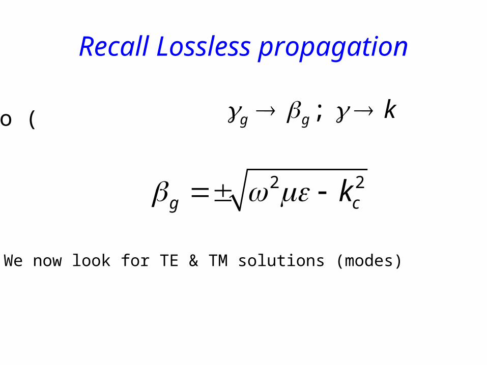
Recall Lossless propagation
This reduces to ( ) ; g g k
2 2g ck
We now look for TE & TM solutions (modes)

Cutoff
The permissible values of kc then can be written
Example: Suppose the TE11 mode is propagating in the guideof radius 5cm at a frequency of 3GHz
We have a cutoff wavenumber of 21.841 1.841/ 5 10
36.82ck a The cutoff frequency is
8
0 0
36.82 3 101.75
22c
c
kf GHz
akr
ck

Example (ctd)
Similarly the phase propagation factor is:
2 2 10 0 50.9 g ck rads m
The wavelength in the guide is
212.3g
g
cm
And the wave impedance is 0 465TEg
g
Z

mode pictures

Dominant mode example
The dominant mode is the TE11,
Design an airfilled circular guide such that only the dominantmode will propagate over a bandwidth of 10GHz.
From slide above we have
11
1.841
2cTE
cf
a
The cutoff of the next higher mode TM01 is the upper bound ofthe bandwidth given by.
01
2.405
2cTM
cf
a

Example continue..The bandwidth is the difference between these two frequencies.
01 11
2.405 1.842 102cTM cTE
cbandwidth f f Ghz
a
from which we find: a = 0.269 cm.
substituting this back into the expressions for the cutofffrequencies we find:
11
01
32.7
42.7
cTE
cTM
f GHz
f GHz
Note that the recommended frequencyrange for TE11 mode propagation forWC-25 (0.635cm diam) is 31.8 - 43.6GHz

Disadvantages• Circular waveguide cross section area is much bigger
than that of corresponding rectangular waveguide used to carry the same signal.
• Easier to manufacture than rectangular• Easier to join together• At frequency in excess of 10 GHz, TE0,1 has the
lowest attenuation than any other guide.
Advantages

Other waveguides• Ridged or flexible waveguides• Ridged waveguides- RG sometime made of single or
double ridges . Hence lower the value of cutoff wavelength. This allow a guide with smaller dimensions to be used for any given frequency.
• Flexible waveguides: sometime we require WG with movement, this may be bending, twisting, stretching or vibration

Waveguide coupling , matching and attenuation
• Practical aspect of their use• Various junctions, accessories, methods of impedance
matching and also attenuation
Methods of exciting waveguideIn order to launch a particular mode , arrangement/combination of one or more antenna is generally used
Couple a coaxial line directly to waveguide
couple waveguide to each other by means of slot in common wall
Antenna should be placed to setup mode and yet matching is essential

When microwave transmission system consist of partly coaxial and partly waveguide
Coupling taper
slot
TEM mode in coaxial is transformed into dominant mode in the waveguide

Slot coupling
• If hole or slot is made in the wall of waveguide , energy will escape from the waveguide through the slot or possible enter into the waveguide from outside.
• Coupling by means of one or more slot can be method of feeding energy into a waveguide from another waveguide or cavity resonator
• Coupling: E field line that would have been terminated by wall enter the second waveguide
• placement of slot interrupts the flow of wall current , magnetic field is setup extending into the second guide

Waveguide joins• Coupling is by means of flange to ensure good mechanical and electrical, hence low
radiation and internal reflection• Rotating join used in radar

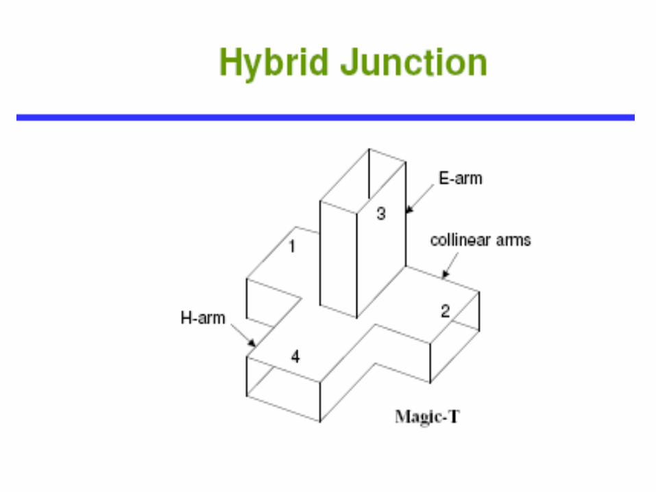
Multiple junction
• To combine two or more signals( or to spilt a signal into two or more parts) in a waveguide system multiple junction is used
– For simple interconnection –T-shaped– Complex- Hybrid T or Hybrid Ring


Impedance matching and turning
• Same as in TL has to be achieved in WG• Obstacle : Reflection in a WG system cause
impedance mismatches hence as in TL find lumped impedance and place in pre-calculated point to overcome the mismatch
• Eg• Irises- introduce capacitive or inductive to the guide
hence mismatch

The screws shown are used as waveguide matcher as for double stub tuner in TL
Screws

Attenuation in waveguide
Waveguide below the cutoff have the following attenuation– Reflection from obstacles, discontinuities, misaligned
waveguide section – Losses due to currents flowing in the waveguide walls– Losses in the dielectric filling the waveguide– 2&3 depends on wall material ,its roughness and frequency
used

leA where 0
2
l Length of waveguide
dBeeA llldB 00
5.5440 loglog20
A waveguide below cutoff is often used as an adjustable, calibrated attenuator for UHF and microwave applications
Adjusting the length of the waveguide hence its attenuation

Calculate the voltage attenuation provided by a 25-cm length of waveguide having a= 1cm and b= 0.5cm, in which a 1-GHz signal is propagated in the dominant mode
Example

• A piece of WG closed at both ends with metallic plane
• Form a standing wave partten and oscillation takes place if it is suitably exicited
• Used as turned circuit at given f
• Type : sphere, cylinder , rectangular prism• Drawback: Resonant freq are harmonically related
Cavities resonant


Application
• The same purpose as turned LC circuits but at higher frequencies
• i.e. input/ output turned circuit of amplifier,• Turned circuit of oscillator• Resonant circuit used for filtering/ mixer
• Cavity meter -microwave frequency measuring device

Microwave components and devices
Auxiliary Componentsdirectional couplers,
baluns, slotted linestiple lines, microstrips

Directional couplers• Sometime known as nonreflecting termination.
• It is necessary to measure power being delivered to a load or an antenna
• Method : sampling techniques which measure fraction of power is used. and total can be calculated
• It is imperative that , only the forward wave in the main line is measured and not reflected one.


Directional couplers
• A Directional coupler is one of the coupling unit used for the purpose of measuring forward waves of the main line
• Example:• The two hole directional coupler consisting of a
piece of TL to be connected in series with the main line, together with the piece of auxiliary line coupled to the main line via two probes through slots in the joined outer walls of the two coaxial

Directional couplers
• The Directivity of a directional coupler is a standard method of measuring the extent of the unwanted waves
• e.i if the ratio of forward to reverse power measured by detector is 30dB, then directional coupler is said to have directivity of 30dB
• Directional coupling define the ratio of the forward wave in the main line to forward wave in the auxiliary line

Baluns• A balun, or balance to unbalance transformer, is a
circuit elements used to connect a balanced line to unbalanced line or antenna
• At LF an ordinary tuned transformer is used with unbalanced primary and centre tapped secondary winding to which the balanced antenna is connected.
• For HF different TL baluns exist for different purpose i.e narrowband and broadband application

Wideband Folded Dipole
Antenna total length approx 90ft
600 Ω Terminating Resistance/Balancing Network
12 : 1 Stepdown Balun to 50 Ω
Example – Barker & Williamson BWD 1.8 – 30 MHz Wideband Folded Dipole
Courtesy of Barker & Williamson Manufacturing Inc.

Baluns types
• The most common baluns are narrowband one – Choke– Sleeve– Bazooka baluns

The slotted Line• A piece of TL is constructed in such a way that the
voltage or current along it can be measured continuously over its length.
• A traveling detector facilitate the easiness of determine distance of probe from either end of TL
• Lecher line –LF OR Slotted Line- HF
• The slotted line must have the same characteristics as the main line connected to it in series

The slotted Line
• Permit convenient and accurate measurement of the position and size of the first voltage maximum from load and any subsequent one, without interfering with the quantities being measured.
• Measurement of these quantities permits calculation of
• Load impedance• Standing wave ratio• Frequency of generator being used.

Microstrip and strip line
• At frequency of about 300MHz, the characteristic of open and shorted TL, have little relevance.
• At low frequency TL would be too long for practical use as reactive components or tuned circuits.
• For HF (300MHz to 3000MHz) applications , special TL constructed with copper patterns on a printed circuit PC board have been developed to interconnect components on PC board

When d btn source and load is few inches or less, coaxial cable TL are impractical to use
Reasons
Connector , terminator and cables themselves are simply too large.
microstrip and stripline uses traces (tracks) on the PC board itself.
Traces can be etched using the same process as other traces on the board
Microstrip and strip line

Microstrip and strip lineMicrostrip have been developed to interconnect components on PC board.
Microstrip occurs when the line are etched onto the surface of the PC board only.
Stripeline occurs when the line are etched in the middle layer of a multilayer PC board
They can be used to construct TL, Inductors, capacitors, turned circuit, filters, phase shifters and impedance matching devices

Microstrip

Microstrip

MicrostripMicrostrip is a flat conductor separated from ground plane by an insulating dielectric material
The ground plane serves as the circuit common point and must be at least 10 times wider than top conductor and must be connected to ground
It is generally 0.5λ or 0.25λ at the frequency of operating and equivalent to unbalanced TL
Short are preferred comparisons to open line cause open have a great tendency to radiate

It depends on its physical characteristics.50-200Ω can be archieved by simply changing its dimensionFor unbalanced Microstrip
Characteristic Impedance
)ln( 8.098.5
41.187
twh
oZ
Where:
Ε=dielectric constant( fibreglass=4.5, Teflon=3)
W=width of copper trace
t=thickness of copper trace
H=distance btn copper trace and the ground plane

Stripline is a flat conductor sandwitched btn two ground
plane
It is more difficult to manufacture than microstrip, it is less
likely to radiate. Hence losses is less than in microstrip
L=0.5λ or 0.25λ and shorted are prefered
Stripline
)ln( 8.0(67.0460
htw
doZ