Embed Size (px)
Citation preview
ISSN: 2319-5967
ISO 9001:2008 Certified International Journal of Engineering Science and Innovative Technology (IJESIT)
Volume 2, Issue 4, July 2013
117
Experimental Studies on a Scraped Surface Ice
Slurry Generator Rajinder Singh, Surendra Singh Kachhwaha
Abstract- In the present experimental study a scraped surface ice slurry generator has been designed, developed and
fabricated successfully with a focus on collection of experimental data related to ice slurry production using 10%, 20%
and 30% concentrations of antifreezes (PG and MEG). Three distinct stages- chilling, nucleation and stable ice slurry
generation period were observed through historical time dependence curves. The minimum ice slurry temperatures
achieved are -11.0 0C and -11.9 0C respectively for 30 % concentration of PG and MEG. It was further observed that the
freezing temperature reduces with increase in antifreeze mass fraction for PG and MEG. Using the experimental data
and the present manufacturing technique opens further possibility for development of a higher capacity ice slurry
generation machine suitable for industrial application.
Index Terms- Ice Slurry, Scraped Surface, Ice Slurry Generator, Antifreezes.
I. INTRODUCTION
During the last couple of decades, some widely used conventional refrigerants have been identified as harmful
for greenhouse substances and also contribute ozone depletion. Therefore, refrigeration industry has been
continuously working to develop alternative refrigerants having good physical and thermodynamic
characteristics besides less adverse effects on the environment. Simultaneously, the research work has also been
done to reduce the amount of refrigerant installations by the use of secondary refrigeration loops. The heat
transfer fluid in these loops is generally water or sometimes an aqueous solution which can be replaced by
diphasic secondary refrigerants such as ice slurries to improve system efficiencies.
The ice slurry is normally the ice crystals distributed in water or an aqueous solution where different substances
are added to achieve reduction in freezing point, viscosity, corrosion behaviour, agglomeration and increase in
heat carrying capacity and thermal conductivity of the fluid phase. Ice slurry has a great potential for the future
due to wide range of industrial applications, ranging from comfort cooling and commercial refrigeration to
industrial production processes and medicine. An important application [1] of an ice slurry system is in the milk
production where high peak loads are to be adjusted.
Ice slurry is a phase-changing secondary fluid consisting of both a liquid state and a solid–state fraction
(composed of fine ice particles). The main purpose of using ice slurry is to take advantage of the stored cooling
energy (in terms of latent heat) in the ice particles (0.1 to 1 mm size) during melting. Sodium chloride, ethanol,
ethylene glycol and propylene glycol are the four most commonly used freezing point depressants [2] used by
the refrigeration industry. Depending on the type of additive and additive concentration, the operating
temperature [3] for ice slurry can be chosen between 0 to -35ºC.
The time required for ice to cover the unscraped cooling surface; the thermal response of the supercooled
solution at the onset of phase change; the heat transfer coefficient on the scraped surface with/without phase
change, and the growth kinetics of ice film spreading along the cooling surface was exhaustively studied by Qin
et al. [4]. Continuous heat extraction is important for the process of freeze concentration of aqueous solutions, in
which water is removed as solid ice. Three typical stages of heat-transfer patterns [5], namely, chilling,
nucleation, and crystallization were identified during the process of freeze concentration in a scraped surface
heat exchanger. Using the Laplace and inverse transform, and incorporating the initial condition of ice
nucleation, an analytical solution was obtained by Qin et al. [6]. Heat transfer phenomena in two types of
eutectic crystallizers have been analyzed by Vaessen et al. [7]. Both increasing and decreasing heat transfer rates
have been observed in crystallizing conditions at increasing scraping rates. Differences are attributed to
geometrical crystallizer characteristics and solid content [8].
For ice slurries to become more widely accepted, however, more engineering information is required on fluid
flow and heat transfer characteristics. An experimental study [9] was carried out on a scraped surface heat
exchanger used for freezing of water–ethanol mixture and aqueous sucrose solution. The influence of various
parameters on heat transfer intensity was established. The heat transfer coefficient and the power consumption
of a laboratory scraped-surface heat exchanger (SSHE) were measured when it was used for freezing a 10 wt. %
sugar solution. Experimental results [10] show that the heat transfer coefficient with phase change (ice
formation) was about three to five times greater than that without phase change. Effect of poly vinyl alcohol
ISSN: 2319-5967
ISO 9001:2008 Certified International Journal of Engineering Science and Innovative Technology (IJESIT)
Volume 2, Issue 4, July 2013
118
(PVA) in inhibiting an increase in ice crystal size in isothermal ice slurries was investigated by Inada and
Modak [11]. Using PVA, which exhibits thermal hysteresis, is a novel technique to completely inhibit the
increase in ice crystal size in isothermal ice slurries. A new type of sensor for in-line measurements of antifreeze
mass fraction in aqueous solutions is described by Ayel et al. [12]. Its principles of operation are based on the
exploitation of the temperature rise that accompanies the freezing of an undercooled solution. Latent heat of
fusion of ice in aqueous solutions was investigated by Kumano et al. [13]
in order to understand the
characteristics of ice slurries used in ice thermal energy storage systems.
The study by Matsumotoa et al [14] focuses on an emulsion as a new thermal storage material for ice storage.
The results indicated that one emulsion was a W/O type emulsion, while the other was an O/W type. Finally,
adaptability of the two emulsions to ice storage was discussed, it was concluded that a high performance ice
slurry could be formed by the W/O type emulsion. Study by Guilpart et al. [15] compares the performance of
several commonly used organic and inorganic ice slurry secondary refrigerants. This study was based on thermo
physical assessments carried out at different operating temperatures. For ice slurry applications there is a need
for accurate freezing point data and for more basic thermo physical property data at low concentrations [16]. An
analytical model has been developed by Hawlader et al. [17] to predict the growth of ice around the injected
super cooled coolant droplets, which involves phase change and heat transfer between layers. Theoretical and
experimental work on a novel ice slurry producing system utilizing inner waste heat was proposed by Li et al
[18]. This system consists of two major processes: an evaporative super cooling process and a liquid
dehumidification process. Lu and Tassou [19] investigated several types of phase change materials for the
preparation of PCM slurries which have potential for cooling applications.
Heat transfer from a jacketed wall of a scraped-surface heat exchanger (SSHE) numerically simulated by
Baccar and Abid. [20] to analyse the hydrodynamic and thermal behaviour under various operating and
geometrical conditions using three-dimensional form of the Navier-Stokes and energy equations. Results show
that geometrical and operating parameters can strongly affect the performance of a heat exchanger. An increase
in the number of scrapers contributes to a higher frequency of the scraped film which would improve heat
transfer performance. With more than four blades, radial dispersion decreases and a rigid-body rotation takes
place. The growth pattern related to the potential for crystal growth as well as the crystal surface topography
have been studied by Grandum et al [21].The crystal shape and size were found to be strongly dependent on the
super cooling in the crystal's surrounding liquid in between a transition temperature. An experimental
investigation of a scraped surface heat exchanger (SSHE) was undertaken by Dumont et al. [22] using visual
observations and the electrochemical technique in order to study the transition between laminar and vortex flows
and to evaluate the wall shear rates. It was established that flow patterns in a SSHE are noticeably different from
those observed in an annular space in the same conditions. A bubbling device was applied by Zhang et al. [23] to
an experimental dynamic ice making system to suppress ice adhesion to the cooling wall. The experimental
dynamic ice making system employed an air compressor to create air bubbles, and for the sake of this purpose,
its ice slurry generator was set up vertically. It was concluded that the air bubbles are effective to suppress ice
adhesion to the cooling wall; however, the air blowing rate of the air compressor should be optimized.
Lasvignottes et al. [24] demonstrated the feasibility to produce ice slurry from super cooled water. This
technology which does not use extra mechanical energy source to operate is a promising alternative to the actual
technologies. However the design must be very accurate to control the super cooled degree at the outside of the
evaporator.
A functional fluid was made by adding a small amount of additive to a water silicone-oil mixture with 90 vol %
water content, and the functional fluid was transformed into an ice slurry by cooling while stirring. The new ice
formation system, proposed by Matsumotoa et al [25] for ice storage based on the results of previous studies,
demonstrated that the ice slurry could be formed continuously for 10 h. Experiments were carried out, varying
operating conditions, and an optimal operating condition was determined to improve performance of the present
system.
A physical model to investigate the non-isothermal freezing kinetic in ice slurry systems was built by
Kousksou et al [26]. Matsumoto et al [27] had proposed application of ice slurry to a cold storage of foods for
widely using the ice slurry. A new ice slurry utilizing the food additive trehalose was tested using the “harvest
method”.
Heat transfer in presence of a high viscosity fluid may be substantially enhanced using heat exchangers
supported by a mechanical agitation system that can also “scrape” the exchange surface. In this case, heat
transfer efficiency depends strongly on exchanger and agitator geometries, agitation methods as well as fluid
characteristics and heat transfer conditions [28].The study performed by Yataghene et al
[29] is focused on
ISSN: 2319-5967
ISO 9001:2008 Certified International Journal of Engineering Science and Innovative Technology (IJESIT)
Volume 2, Issue 4, July 2013
119
experimental analysis of the flow patterns inside SSHE under isothermal and continuous flow conditions.
Experimental flow pattern analyses are the basis for further experimental explorations of mixing and heat
exchange mechanism. Thongwik et al [30] studied the heat transfer phenomenon of melting slurry ice on
external surface of a copper helical coil. The experimental results show that, with small coil diameter, high mass
flow rate of circulating water and low ice fraction, high heat transfer coefficient of the slurry ice at the warm
helical coil surface is obtained.
Most crystallization models for ice slurries are based on the equilibrium thermodynamic approach.
Che´gnimonhan et al [31] presented results of simulations grounded on classical nucleation theory and crystal
growth included in global Nakamuratype kinetics coupled with the one-dimensional nonlinear heat equation,
another way to model the phase change.
Ice storage is a potential energy saving method for air conditioning systems and is an ideal material for ice
storage. The conventional ice slurry producing method using super cooled water suffers from the instability of
ice block and depends heavily on electric power. A novel ice slurry producing system utilizing inner waste heat
was proposed by Li et al. [32]. Compared with the conventional system, this new system can alleviate the
burden on electric power and raise the efficiency. The basic crystallization principles and heat transfer
mechanisms in current ice generators are not yet fully understood. To elucidate the heat transfer mechanisms,
heat transfer measurements are presented by Stamatiou et al [33] in a prototype compact ice generator.
Turbulent fluid flow and related solid particle behavior in the direct vicinity of the heat exchanging surface of a
scraped heat exchanger crystallizer was studied by Pascuala et al [34]. The main goal was the design of scraper
geometries that enhance heat transfer by perturbing the thermal boundary layer, and effectively scrape off
particles that nucleate, grow and adhere onto the heat exchanger surface. The Ultrasonic Doppler Method
(UDM) has been applied by Vuarnoz et al. [35] to the process of ice slurry generation by direct injection of a
refrigerant into an aqueous solution. The main objective of this work has been to investigate the fluid dynamic
behavior of evaporating refrigerant drops in an immiscible fluid and the approach taken has been to evaluate
how suitable the UDM technique is for such investigations.
Pronk et al [36] performed a dynamic simulation of an experimental set-up in order to predict heat transfer
coefficients in a fluidized bed ice slurry generator. A comparison between experiments and results from
simulations pointed out that both models overestimate heat transfer coefficients and that crystallization does not
affect the heat transfer process significantly. A possible explanation for the latter phenomenon is that the
crystallization takes place in the bulk of the fluidized bed instead of near the wall. A super-cooling ice slurry
generator type was experimentally tested and compared by Mouneer et al [37] with a traditional scraped surface
type. A new method of ice slurry generation without the deposition of an ice layer on a cooled surface was
developed by Koji et al. [38].
The recent review of the literature (as mentioned above) shows that there are broadly six methods used for ice
slurry generation namely: (i) mechanical scraper method (also known as harvest method) (ii) fluidized bed
method, (iii) direct injection method, (iv) vacuum freezing method, (v) oscillatory moving cooled wall method,
and (vi) super-cooling water. The investment and operating costs of each of these methods is an important
parameter during system selection procedure. In the mechanical scraper method the refrigerant evaporates in a
double-wall cylinder. Through the inside space, bounded by the inner cylinder, the water or aqueous solution
flows and the ice crystals are created. A rotary sharp edged scraper scrapes the ice growing on the cooling
surface. The scraped surface generator has a large surface for the ice crystal creation per unit volume of ice
slurry generator. In the fluidized bed method, the ice slurry generation process is performed using liquid–solid
fluidized bed heat exchangers. In the direct injection method, the refrigerant is directly injected into the water
domain. Liquid droplets of refrigerant enter through nozzles, normally at the bottom of the generator, and start
to evaporate. The growing droplet/bubbles, moving upwards by buoyancy rise to the top of the water containing
column. Vacuum freezing method has been investigated by ethanol solution and pure water. In the oscillatory
moving cooled wall method, an oscillatory motion is applied to the cooled surfaces on which the ice layers are
formed, and removed by the vibration generated during the oscillatory motion. In the super-cooling water
method, the ice slurry is produced with low ice concentration by using a typical design of shell and tube type,
but the initiation of the freezing should be controlled to adjust the produced ice concentration without system
blockage. In the developing countries a widespread utilization of ice slurry systems for industrial applications
has not taken place yet which is mainly attributed to the high investment costs of commercially available (only
imported) ice slurry generators. The objectives of this study are design and fabrication of a small scale scraped
surface ice slurry generator test rig through commonly used manufacturing processes employed by small and
medium scale industries and collection of experimental data to understand ice crystallization mechanism in the
ISSN: 2319-5967
ISO 9001:2008 Certified International Journal of Engineering Science and Innovative Technology (IJESIT)
Volume 2, Issue 4, July 2013
120
microscopic scale, and heat transfer and fluid mechanics involving agitation and phase change in the macro
scale for ice slurry production using Propylene Glycol (PG) and Mono Ethylene Glycol (MEG) water based
solution at different solute concentrations. Experimental data have been collected on a prototype to explore the
possibility for development of a future large capacity ice slurry generation machine.
II. EXPERIMENTAL SETUP AND PROCEDURE
In the present experimental study „scraped surface ice slurry generator‟ of 5 liter capacity has been designed,
developed and fabricated [refer Fig.1 (a) to (c)]. Experiments were carried out to collect the performance data
for ice slurry production.
A. Working Principle and Specifications of Scraped Surface Ice Slurry Generator
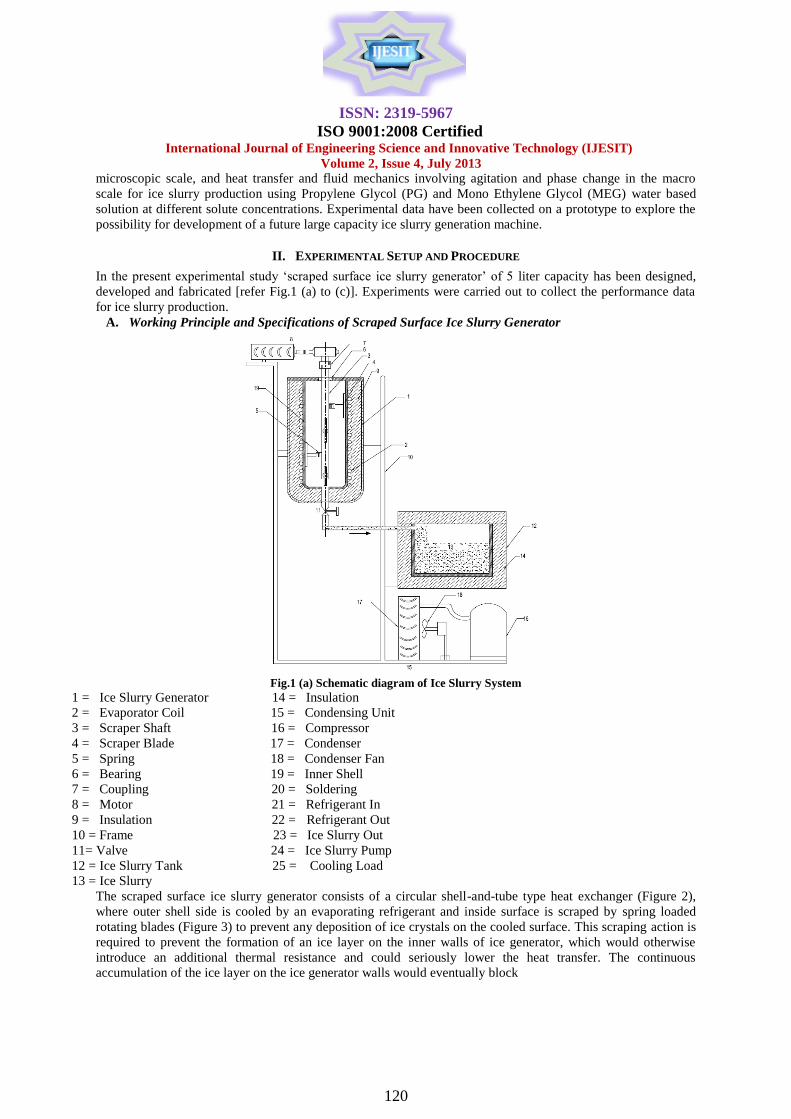
Fig.1 (a) Schematic diagram of Ice Slurry System
1 = Ice Slurry Generator 14 = Insulation
2 = Evaporator Coil 15 = Condensing Unit
3 = Scraper Shaft 16 = Compressor
4 = Scraper Blade 17 = Condenser
5 = Spring 18 = Condenser Fan
6 = Bearing 19 = Inner Shell
7 = Coupling 20 = Soldering
8 = Motor 21 = Refrigerant In
9 = Insulation 22 = Refrigerant Out
10 = Frame 23 = Ice Slurry Out
11= Valve 24 = Ice Slurry Pump
12 = Ice Slurry Tank 25 = Cooling Load
13 = Ice Slurry
The scraped surface ice slurry generator consists of a circular shell-and-tube type heat exchanger (Figure 2),
where outer shell side is cooled by an evaporating refrigerant and inside surface is scraped by spring loaded
rotating blades (Figure 3) to prevent any deposition of ice crystals on the cooled surface. This scraping action is
required to prevent the formation of an ice layer on the inner walls of ice generator, which would otherwise
introduce an additional thermal resistance and could seriously lower the heat transfer. The continuous
accumulation of the ice layer on the ice generator walls would eventually block
ISSN: 2319-5967
ISO 9001:2008 Certified International Journal of Engineering Science and Innovative Technology (IJESIT)
Volume 2, Issue 4, July 2013
121
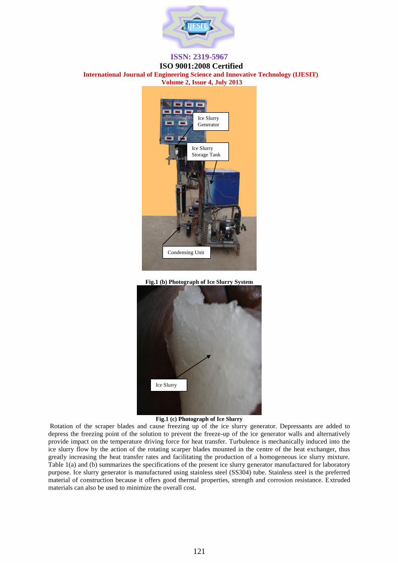
Fig.1 (b) Photograph of Ice Slurry System
Fig.1 (c) Photograph of Ice Slurry
Rotation of the scraper blades and cause freezing up of the ice slurry generator. Depressants are added to
depress the freezing point of the solution to prevent the freeze-up of the ice generator walls and alternatively
provide impact on the temperature driving force for heat transfer. Turbulence is mechanically induced into the
ice slurry flow by the action of the rotating scarper blades mounted in the centre of the heat exchanger, thus
greatly increasing the heat transfer rates and facilitating the production of a homogeneous ice slurry mixture.
Table 1(a) and (b) summarizes the specifications of the present ice slurry generator manufactured for laboratory
purpose. Ice slurry generator is manufactured using stainless steel (SS304) tube. Stainless steel is the preferred
material of construction because it offers good thermal properties, strength and corrosion resistance. Extruded
materials can also be used to minimize the overall cost.
Ice Slurry
Condensing Unit
Ice Slurry
Generator
Ice Slurry
Storage Tank
ISSN: 2319-5967
ISO 9001:2008 Certified International Journal of Engineering Science and Innovative Technology (IJESIT)
Volume 2, Issue 4, July 2013
122
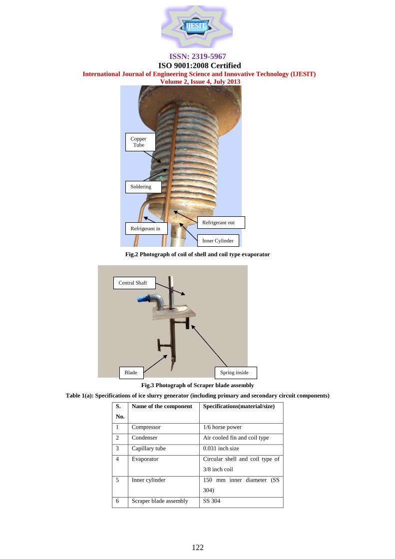
Fig.2 Photograph of coil of shell and coil type evaporator
Fig.3 Photograph of Scraper blade assembly
Table 1(a): Specifications of ice slurry generator (including primary and secondary circuit components)
S.
No.
Name of the component Specifications(material/size)
1 Compressor 1/6 horse power
2 Condenser Air cooled fin and coil type
3 Capillary tube 0.031 inch size
4 Evaporator Circular shell and coil type of
3/8 inch coil
5 Inner cylinder 150 mm inner diameter (SS
304)
6 Scraper blade assembly SS 304
Central Shaft
Blade
Spring inside
Copper
Tube
Soldering
Refrigerant in
Refrigerant out
Inner Cylinder
ISSN: 2319-5967
ISO 9001:2008 Certified International Journal of Engineering Science and Innovative Technology (IJESIT)
Volume 2, Issue 4, July 2013
123
7 Ice slurry tank 300 cubic mm (SS 304)
8 Ice slurry circulation
pump
(SS 304), 1/4 horse power
Table 1(b): Technical specifications of ice slurry generator
Specifications The present design
Ice slurry side
Tube Material 304-Grade Stainless Steel
Evaporator type
arrangement
Vertical
Freezing point depressant Propylene glycol, mono ethylene
glycol
Crystal size (mm) 0.2- 0.3
Inner tube diameter (m) 0.15
Tube length (m) 0.30
Heat transfer area (m2) 0.1414
Agitation mechanism SS 304 scraper blades 7.5 cm (L),
1.85 cm (W)
Agitation speed (rpm) 24
Refrigerant side
Evaporator type Circular shell and coil type of 3/8
inch coil
Refrigerant type R134a
The stainless steel (SS 304) cylinder (150 mm inner diameter, 3 mm thickness and 300 mm length) is used as
the main body for ice slurry generator. A copper tube (0.93 cm diameter) was wrapped in a spiral coil shape (16
numbers of turns) around the outer surface of the main cylinder (Figure 3). This copper tube is soldered with the
outer periphery of the cylinder for proper contact to enhance the heat transfer effect. The total 40 feet length of
copper tube was consumed. This type of copper coil configuration (evaporator) ensures proper turbulence for
the primary refrigerant (R134a). Around the copper tube coil, polyurethane foam insulation of 7.5 cm thickness
is provided and inserted between the inner and outer cylinders. The insulating material is compatible with the
temperature of the cooling medium to minimize any heat gains from the surroundings. The two concentric
cylinders are connected by welded neck flanged ends. The scraper blade assembly used in the present work
consisted of four staggered spring loaded blades attached to the 25 mm diameter scraper shaft located centrally
in the inner cylinder. Each blade is 75 mm long in the axial direction and 18.5 mm wide in the radial direction.
An electric speed motor is mounted at the top of ice slurry generator to rotate the scraper shaft. The scraper
blade assembly is coupled to electric motor (1 hp, 1425 rpm) via a reducing gear box of ratio 1:60 to provide
rotational speed of 24 rpm to the scraper shaft. The rotational speed of the scraping mechanism was kept
constant in all experimental observations presented herein this research which is the minimum speed with the
lowest internal thermal resistance of ice layer formed.
B. Experimental Setup A schematic diagram of the experimental apparatus is presented in Fig. 4. The present condensing refrigeration
unit consisting of a compressor (1/6 hp, 1-φ, 230V, 50 Hz), air cooled condenser (fin and coil type 220 ×230
mm, 2 row deep, 3/8 inch diameter copper tubes, 6 fins per inch, fan 1300 rpm) and capillary tube ( 5/16 inch
size having two 7 feet long passage) and measurement facilities. Ice slurry tank (300 mm×300 mm×300 mm
size, insulated with 60 mm thick polyurethane foam) is connected with ice slurry generator through a ice slurry
circulation pump (1/4 hp). This unit supplies the refrigerant to the coil of the ice slurry generator (referred as
evaporator in the refrigeration cycle in Fig.4) where evaporating refrigerant at lower pressure
ISSN: 2319-5967
ISO 9001:2008 Certified International Journal of Engineering Science and Innovative Technology (IJESIT)
Volume 2, Issue 4, July 2013
124
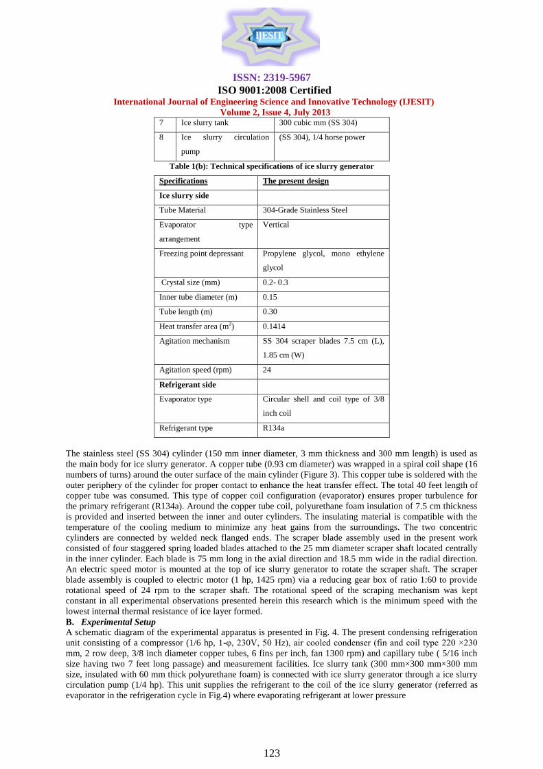
Fig 4 (a) Schematic of Direct-expansion, single-stage mechanical vapor compression refrigeration system of scraped
surface ice slurry generator
Fig.4 (b) Pressure-enthalpy diagram
Withdraws heat from the binary solution which is finally converted into ice slurry inside the generator. At the
exit of the evaporator, a refrigerant vapor of enough superheat is generated from this indirect heat exchange
process, recompressed and recompensed at high pressure to complete the refrigeration cycle. During the
experimentation, ice slurries are made of an aqueous solutions of propylene glycol [PG] and mono ethylene
glycol [MEG] having the initial weight concentration of 10%, 20%, and 30%, respectively.
C. Measurements and Data Collection
The temperatures at condenser inlet and outlet, compressor suction and discharge, ice slurry tank and ice slurry
in the ice slurry generator were measured by resistance-temperature detectors with a range of -50 ºC to 0 ºC to
99 ºC and accuracy of 0.01 K. The pressures of primary refrigerant at condenser inlet and outlet, compressor
suction and discharge, expansion outlet were measured using pressure transmitters with a range of 0 to 20 bar
having accuracy of 0.01 bar. Mass flow rate of primary refrigerant was measured using rotameter. Propylene
Glycol (PG) and Mono Ethylene Glycol (MEG) were used as additives an air-cooled, direct-expansion, single-
stage mechanical vapor compression refrigeration system with R134a as primary refrigerant is used for scraped
surface ice slurry generator. A pressure-enthalpy diagram of this system is shown in Fig. 4 (b). Table 2 (a) and
Table 2 (b) summarizes the measured operating thermodynamic properties at inlet and outlet of various primary
refrigerant components. Table 2(a) Measured Thermodynamic Properties (MEG as Antifreeze in Ice Slurry Generator)
State Pressure (kPa) Temperature (°C)
10% 20% 30% 10% 20% 30%
1. Compressor suction 100 083 068 -6.9 -8.9 -12.0
2. Compressor discharge 1051 1005 985 46.7 45.7 42.1
3. Condenser inlet 1014 971 946 46.6 44.9 41.6
4. Condenser outlet 1005 961 939 36.3 35.5 35.4
ISSN: 2319-5967
ISO 9001:2008 Certified International Journal of Engineering Science and Innovative Technology (IJESIT)
Volume 2, Issue 4, July 2013
125
5. After expansion 108 091 077 -7.0 -9.5 -12.1
6. Ice slurry temperature -3.4 -7.1 -11.9
Table 2(b) Measured Thermodynamic Properties (PG as Antifreeze in Ice Slurry Generator)
State Pressure (kPa) Temperature (°C)
10% 20% 30% 10% 20% 30%
1. Compressor suction 104 082 062 -5.0 -8.7 -11.2
2. Compressor discharge 1045 1006 972 45.9 43.0 41.2
3. Condenser inlet 1010 972 935 45.8 42.6 40.9
4. Condenser outlet 999 962 929 35.7 35.3 35.2
5. After expansion 112 091 071 -6.8 -9.1 -11.5
6. Ice slurry temperature -2.9 -6.4 -11.0
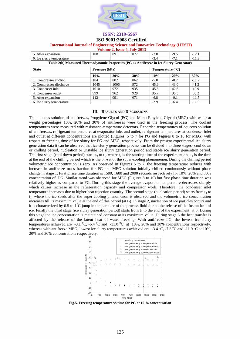
III. RESULTS AND DISCUSSIONS
The aqueous solution of antifreezes, Propylene Glycol (PG) and Mono Ethylene Glycol (MEG) with water at
weight percentages 10%, 20% and 30% of antifreezes were used in the freezing process. The coolant
temperatures were measured with resistance-temperature detectors. Recorded temperatures of aqueous solution
of antifreezes, refrigerant temperatures at evaporator inlet and outlet, refrigerant temperatures at condenser inlet
and outlet at different concentrations are plotted (Figures. 5 to 7 for PG and Figures 8 to 10 for MEG) with
respect to freezing time of ice slurry for PG and MEG, respectively. From the present experimental ice slurry
generation data it can be observed that ice slurry generation process can be divided into three stages- cool down
or chilling period, nucleation or unstable ice slurry generation period and stable ice slurry generation period.
The first stage (cool down period) starts t0 to t1, where t0 is the starting time of the experiment and t1 is the time
at the end of the chilling period which is the on-set of the super-cooling phenomenon. During the chilling period
volumetric ice concentration is zero. As observed in Figures 5 to 7, the freezing temperature reduces with
increase in antifreeze mass fraction for PG and MEG solution initially chilled continuously without phase
change in stage 1. First phase time duration is 1500, 1600 and 2000 seconds respectively for 10%, 20% and 30%
concentration of PG. Similar trend was observed for MEG (Figures 8 to 10) but first phase time duration was
relatively higher as compared to PG. During this stage the average evaporator temperature decreases sharply
which causes increase in the refrigeration capacity and compressor work. Therefore, the condenser inlet
temperature increases due to higher heat rejection quantity. The second stage (nucleation period) starts from t1 to
t2, where the ice seeds after the super cooling phenomenon is observed and the volumetric ice concentration
increases till its maximum value at the end of this period (at t2). In stage 2, nucleation of ice particles occurs and
it is characterized by 0.5 to 10C jump in temperature of the process fluid due to the release of the fusion heat of
ice. Finally the third stage (ice slurry generation period) starts from t2 to the end of the experiment, at tf. During
this stage the ice concentration is maintained constant at its maximum value. During stage 3 the heat transfer is
affected by the release of the latent heat of water freezing. With antifreeze PG, the lowest ice slurry
temperatures achieved are -3.1 0C, -6.4
0C and -11.0
0C at 10%, 20% and 30% concentrations respectively,
whereas with antifreeze MEG, lowest ice slurry temperatures achieved are -3.4 0C, -7.3
0C and -11.9
0C at 10%,
20% and 30% concentrations respectively.
Fig.5. Freezing temperature vs time for PG at 10 % concentration
0 500 1000 1500 2000 2500 3000 3500 4000 4500-20
-10
0
10
20
30
40
50
60
70
80
90
Time (t) (s)
Tem
pera
ture
(T
) (D
eg.C
)
t0
tf
t1
t2
Ice slurry temperature
Refrigerant temp.at evaporator inlet.
Refrigerant temp.at evaporator outlet.
Refrigerant temp.at condenser inlet.
Refrigerant temp.at condenser outlet.
ISSN: 2319-5967
ISO 9001:2008 Certified International Journal of Engineering Science and Innovative Technology (IJESIT)
Volume 2, Issue 4, July 2013
126
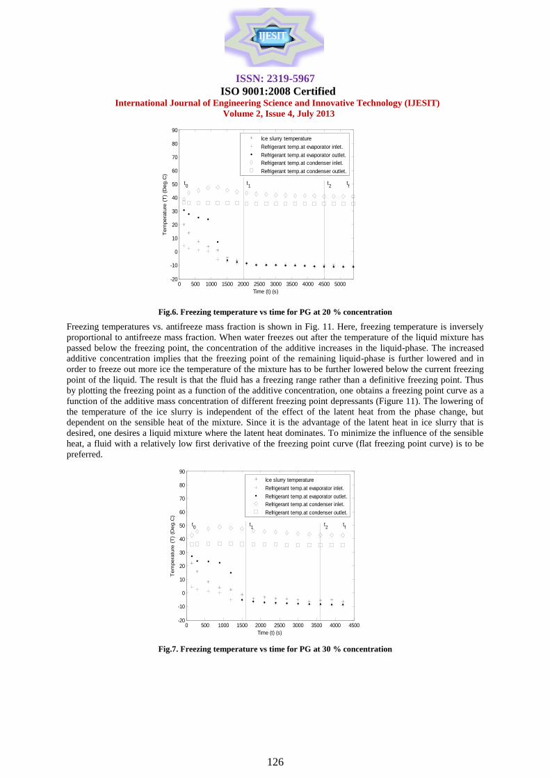
Fig.6. Freezing temperature vs time for PG at 20 % concentration
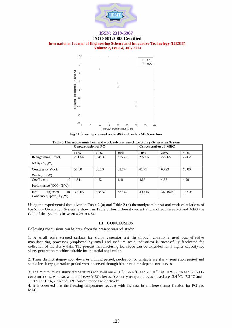
Freezing temperatures vs. antifreeze mass fraction is shown in Fig. 11. Here, freezing temperature is inversely
proportional to antifreeze mass fraction. When water freezes out after the temperature of the liquid mixture has
passed below the freezing point, the concentration of the additive increases in the liquid-phase. The increased
additive concentration implies that the freezing point of the remaining liquid-phase is further lowered and in
order to freeze out more ice the temperature of the mixture has to be further lowered below the current freezing
point of the liquid. The result is that the fluid has a freezing range rather than a definitive freezing point. Thus
by plotting the freezing point as a function of the additive concentration, one obtains a freezing point curve as a
function of the additive mass concentration of different freezing point depressants (Figure 11). The lowering of
the temperature of the ice slurry is independent of the effect of the latent heat from the phase change, but
dependent on the sensible heat of the mixture. Since it is the advantage of the latent heat in ice slurry that is
desired, one desires a liquid mixture where the latent heat dominates. To minimize the influence of the sensible
heat, a fluid with a relatively low first derivative of the freezing point curve (flat freezing point curve) is to be
preferred.
Fig.7. Freezing temperature vs time for PG at 30 % concentration
0 500 1000 1500 2000 2500 3000 3500 4000 4500 5000-20
-10
0
10
20
30
40
50
60
70
80
90
Time (t) (s)
Tem
pera
ture
(T
) (D
eg.C
)
t0
tf
t1
t2
Ice slurry temperature
Refrigerant temp.at evaporator inlet.
Refrigerant temp.at evaporator outlet.
Refrigerant temp.at condenser inlet.
Refrigerant temp.at condenser outlet.
0 500 1000 1500 2000 2500 3000 3500 4000 4500-20
-10
0
10
20
30
40
50
60
70
80
90
Time (t) (s)
Tem
pera
ture
(T
) (D
eg.C
)
t0
tf
t1
t2
Ice slurry temperature
Refrigerant temp.at evaporator inlet.
Refrigerant temp.at evaporator outlet.
Refrigerant temp.at condenser inlet.
Refrigerant temp.at condenser outlet.
ISSN: 2319-5967
ISO 9001:2008 Certified International Journal of Engineering Science and Innovative Technology (IJESIT)
Volume 2, Issue 4, July 2013
127
0 500 1000 1500 2000 2500 3000 3500 4000 4500-20
-10
0
10
20
30
40
50
60
70
80
90
Time (t) (s)
Tem
pera
ture
(T
) (D
eg.C
)
t0
tf
t1
t2
Ice slurry temperature
Refrigerant temp.at evaporator inlet.
Refrigerant temp.at evaporator outlet.
Refrigerant temp.at condenser inlet.
Refrigerant temp.at condenser outlet.
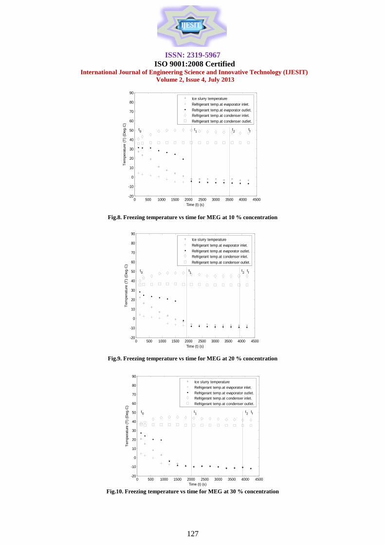
Fig.8. Freezing temperature vs time for MEG at 10 % concentration
0 500 1000 1500 2000 2500 3000 3500 4000 4500-20
-10
0
10
20
30
40
50
60
70
80
90
Time (t) (s)
Tem
pera
ture
(T
) (D
eg.C
)
t0
tf
t1
t2
Ice slurry temperature
Refrigerant temp.at evaporator inlet.
Refrigerant temp.at evaporator outlet.
Refrigerant temp.at condenser inlet.
Refrigerant temp.at condenser outlet.
Fig.9. Freezing temperature vs time for MEG at 20 % concentration
Fig.10. Freezing temperature vs time for MEG at 30 % concentration
0 500 1000 1500 2000 2500 3000 3500 4000 4500-20
-10
0
10
20
30
40
50
60
70
80
90
Time (t) (s)
Tem
pera
ture
(T
) (D
eg.C
)
t0
tf
t1
t2
Ice slurry temperature
Refrigerant temp.at evaporator inlet.
Refrigerant temp.at evaporator outlet.
Refrigerant temp.at condenser inlet.
Refrigerant temp.at condenser outlet.
ISSN: 2319-5967
ISO 9001:2008 Certified International Journal of Engineering Science and Innovative Technology (IJESIT)
Volume 2, Issue 4, July 2013
128
0 5 10 15 20 25 30 35 40-16
-14
-12
-10
-8
-6
-4
-2
0
Antifreeze Mass Fraction (x) (%)
Fre
ezin
g T
em
pera
ture
(T
f) (
Deg.C
)
PG
MEG
Fig.11. Freezing curve of water-PG and water- MEG mixture
Table 3 Thermodynamic heat and work calculations of Ice Slurry Generation System
Concentration of PG Concentration of MEG
10% 20% 30% 10% 20% 30%
Refrigerating Effect,
N= h1 - h5 (W)
281.54 278.39 275.75 277.65 277.65 274.25
Compressor Work,
W= h2- h1 (W)
58.10 60.18 61.74 61.49 63.23 63.80
Coefficient of
Performance (COP=N/W)
4.84 4.62 4.46 4.55 4.38 4.29
Heat Rejected in
Condenser, Qc=h2-h4 (W)
339.65 338.57 337.49 339.15 340.8419 338.05
Using the experimental data given in Table 2 (a) and Table 2 (b) thermodynamic heat and work calculations of
Ice Slurry Generation System is shown in Table 3. For different concentrations of additives PG and MEG the
COP of the system is between 4.29 to 4.84.
III. CONCLUSION
Following conclusions can be draw from the present research study:
1. A small scale scraped surface ice slurry generator test rig through commonly used cost effective
manufacturing processes (employed by small and medium scale industries) is successfully fabricated for
collection of ice slurry data. The present manufacturing technique can be extended for a higher capacity ice
slurry generation machine suitable for industrial application.
2. Three distinct stages- cool down or chilling period, nucleation or unstable ice slurry generation period and
stable ice slurry generation period were observed through historical time dependence curves.
3. The minimum ice slurry temperatures achieved are -3.1 0C, -6.4
0C and -11.0
0C at 10%, 20% and 30% PG
concentrations, whereas with antifreeze MEG, lowest ice slurry temperatures achieved are -3.4 0C, -7.3
0C and -
11.9 0C at 10%, 20% and 30% concentrations respectively.
4. It is observed that the freezing temperature reduces with increase in antifreeze mass fraction for PG and
MEG.
ISSN: 2319-5967
ISO 9001:2008 Certified International Journal of Engineering Science and Innovative Technology (IJESIT)
Volume 2, Issue 4, July 2013
129
REFERENCES
[1] Cecilia Hägg, “Ice Slurry as Secondary Fluid in Refrigeration Systems Fundamentals and Applications in
Supermarkets,” Licentiate Thesis, Stockholm, School of Industrial Engineering and Management Department of Energy
Technology Division of Applied Thermodynamics and Refrigeration, November 2005.
[2] Åke Melinder, „Thermophysical Properties of Aqueous Solutions Used as Secondary Working Fluids,” Doctoral Thesis,
School of Industrial Engineering and Management Royal Institute of Technology, KTH Stockholm, Division of Applied
Thermodynamics and Refrigeration Dept. of Energy Technology Sweden, 2007.
[3] M. Kauffeld, M.J. Wang, V. Goldstein, K.E. Kasza, “Ice Slurry Applications,” International Journal of Refrigeration,
vol. 33, pp. 1491-1505,2010.
[4] Frank G.F. Qin, Xiao Dong Chen , Kevin Free, “Freezing on subcooled surfaces, phenomena, modeling and
applications,” International Journal of Heat and Mass Transfer, vol. 52, , pp. 1245–1253 , 2009.
[5] Frank G. F. Qin, Xiao Dong Chen, and Andrew B. Russell, “Heat Transfer at the Subcooled-Scraped Surface,
with/without Phase Change, “AIChE Journal, vol. 49, no. 8, pp. 1947- 1955, August 2003.
[6] Frank G.F. Qin, Jian Chao Zhao , Andrew B. Russell ,1, Xiao Dong Chen , John J. Chen , Lindsay Robertson,
“Simulation and experiment of the unsteady heat transport in the onset time of nucleation and crystallization of ice from
the subcooled solution,” International Journal of Heat and Mass Transfer, vol. 46, pp. 3221–3231,2003.
[7] R.J.C. Vaessen, M.M. Seckler, G.J. Witkamp, “Heat transfer in scraped eutectic crystallizers,” International Journal of
Heat and Mass Transfer, vol. 47, , pp. 717–728 , 2004.
[8] Frank G.F. Qin, Xiao Dong Chen, Mohammed M. Farid, “Growth kinetics of ice films spreading on a subcooled solid
surface,” Separation and Purification Technology, vol. 39, pp. 109–121, 2004.
[9] Mohamed Ben Lakhdar , Rosalia Cerecero , Graciela Alvarez , Jacques Guilpart , Denis Flick , Andr Lallemand, “Heat
transfer with freezing in a scraped surface heat exchanger,” Applied Thermal Engineering, vol. 25, pp. 45–60, 2005.
[10] Frank Qin , Xiao Dong Chen, Shashini Ramachandra , Kevin Free,” Heat transfer and power consumption in a scraped-
surface heat exchanger while freezing aqueous solutions,” Separation and Purification Technology, vol. 48, pp. 150–
158, 2006.
[11] Takaaki Inada, Poly Rani Modak, “Growth control of ice crystals by poly(vinyl alcohol) and antifreeze protein in ice
slurries, “ Chemical Engineering Science, vol. 61, pp. 3149 – 3158 , 2006.
[12] Vincent Ayel , Olivier Lottin , Elena Popa , Hassan Peerhossaini, “Using undercooling to measure the freezing points of
aqueous solutions,” International Journal of Thermal Sciences, vol. 44, pp. 11–20, 2005.
[13] Hiroyuki Kumano, Tatsunori Asaoka, Akio Saito, Seiji Okawa, “Study on latent heat of fusion of ice in aqueous
solutions,” International Journal of Refrigeration, vol. 30, pp. 267-273, 2007.
[14] Koji Matsumotoa,, Ken Oikawab, Masashi Okadac, Yoshikazu Teraokad, Tetsuo Kawagoe, “Study on high
performance ice slurry formed by cooling emulsion in ice storage (discussion on adaptability of emulsion to thermal
storage material),” International Journal of Refrigeration, vol. 29, pp. 1010-1019 , 2006.
[15] Jacques Guilpart, Evangelos Stamatiou, Anthony Delahaye, Laurence Fournaison, “Comparison of the performance of
different ice slurry types depending on the application temperature,” International Journal of Refrigeration, vol. 29, pp.
781–788 , 2006.
[16] A. Melinder, E. Granryd, “Using property values of aqueous solutions and ice to estimate ice concentrations and
enthalpies of ice slurries,“ International Journal of Refrigeration, vol. 28, pp. 13–19 , 2005.
[17] M.N.A. Hawlader, M.A. Wahed, “Analyses of ice slurry formation using direct contact heat transfer,” Applied Energy,
vol. 86, pp. 1170–1178 , 2009.
[18] Xiu-Wei Li, Xiao-Song Zhang, Rong-Quan Cao, Xiu-Zhang Fu, “A novel ice slurry producing system Producing ice by
utilizing inner waste heat Energy,” Conversion and Management, vol. 50, pp. ) 2893–2904, 2009..
[19] W.Lu, S.A.Tassou, “Experimental study of the thermal characteristics of phase change slurries for active cooling,”
Applied Energy, vol. 91, pp. 366–374, 2012.
[20] Mounir Baccar , Mohamed Salah Abid, “Numerical analysis of three-dimensional flow and thermal behaviour in a
scraped-surface heat exchanger,” Rev Gt!n Therm Elsevier, vol. 36, pp. 782-790 , 1997 .
[21] Svein Grandum, Akira Yabe, Kazuya Nakagomi, Makoto Tanaka, Fumio Takemura, Yasunori Kobayashi, Per-Erling
Frivik, „Analysis of ice crystal growth for a crystal surface containing adsorbed antifreeze proteins,” Journal of Crystal
Growth, vol. 205, pp. 382-390 , 1999.
ISSN: 2319-5967
ISO 9001:2008 Certified International Journal of Engineering Science and Innovative Technology (IJESIT)
Volume 2, Issue 4, July 2013
130
[22] Eric Dumont , Francine Fayolle , Jack Legrand, “Flow regimes and wall shear rates determination within a scraped
surface heat exchanger,” Journal of Food Engineering, vol. 45, pp. 195-207 , 2000.
[23] X.J. Zhang , L.M. Qiu , P. Zhang , L. Liu , Z.H. Gan, “Performance improvement of vertical ice slurry generator by
using bubbling device,” Energy Conversion and Management, vol. 49, pp. 83–88 , 2008.
[24] Jean Castaing-Lasvignottes, Thomas David, Jean-Pierre Be´de´carrats Franc¸oise Strub, “Dynamic modelling and
experimental study of an ice generator heat exchanger using supercooled water,‟ Energy Conversion and Management,
vol. 47, pp. 3644–3651, 2006.
[25] Koji Matsumotoa,, Yutaka Suzukib, Masashi Okadac,1, Yoshikazu Teraokad, Tetsuo Kawagoe, “Study on continuous
ice slurry formation using functional fluid for ice storage Discussion of optimal operating conditions,” International
Journal of Refrigeration, vol. 29, pp. 1208-1217 , 2006.
[26] T. Kousksou, A. Jamil, A. Arid, S. Jegadheeswaran, Y. Zeraouli, “Crystallisation kinetics with nucleation phenomenon:
Ice slurry system,” International Journal of Refrigeration, vol. 35, pp. 1921–1939, 2012.
[27] Koji Matsumoto , Mitsuru Inuzuka , Yoshikazu Teraoka , Keisuke Hayashi, Keisuke Murahashi, “Fundamental study
on freezing characteristics of trehalose solution (investigation based on scraping characteristics),” International Journal
of Refrigeration, vol. 35, pp. 897–906, 2012.
[28] L. Saraceno, G. Boccardi, G.P. Celata, R. Lazzarini, R. Trinchieri, “Development of two heat transfer correlations for a
scraped surface heat exchanger in an ice-cream machine,” Applied Thermal Engineering, vol. 31, pp. 4106-4112,
20011.
[29] Mourad Yataghene, Fayolle Francine, Legrand Jack, “Flow patterns analysis using experimental PIV technique inside
scraped surface,” Applied Thermal Engineering, vol. 31, pp. 2855-2868, 2011.
[30] Sathaporn Thongwik , Tanongkiat Kiatsiriroat, Atipoang Nuntaphan, “Heat transfer model of slurry ice melting on
external surface of helical coil,” International Communications in Heat and Mass Transfer, vol. 35, pp. 1335–1339,
2008.
[31] V. Che´gnimonhan, C. Josset, H. Peerhossaini, “Ice slurry crystallization based on kinetic phase-change modeling,”
International Journal of Refrigeration, vol. 33, pp. 1559-1568, 2010.
[32] Xiu-Wei Li, Xiao-Song Zhang , Rong-Quan Cao, Xiu-Zhang F, “A novel ice slurry producing system: Producing ice by
utilizing inner waste heat,” Energy Conversion and Management, vol. 50, pp. 2893–2904, 2009.
[33] E. Stamatioua, J.W. Meewisseb,1, M. Kawaji, “Ice slurry generation involving moving parts,” International Journal of
Refrigeration, vol. 28, pp. 60–72, 2005.
[34] M. Rodriguez Pascuala,∗ , J.J.Derksenb, G.M.VanRosmalena, G.J.Witkamp, “Flow and particle motion in scraped heat
exchanger crystallizers,” Chemical Engineering Science, vol. 64, no. 24, pp. 5153-5161, 2009.
[35] Didier Vuarnoz, D.Ata-Caesar, Osmann Sari, Peter William Egolf, “Ultrasonic measurements in ice slurry generation
by direct contact evaporation,” 4th International Symposium on Ultrasonic Doppler Method for Fluid Mechanics and
Fluid Engineering Sapporo, pp. 6–8, September, 2004.
[36] P.Pronk, J.W.Meewisse, C.A.Infante Ferreira, “Heat transfer model for a fluidised bed ice slurry generator,” Presented
at the 4th Workshop on Ice Slurries of the IIR, 12-13, Osaka (Japan), November 2001.
[37] T.A. Mouneer, M.S. El-Morsi, M.A. Nosier, N.A. Mahmoud, “Heat transfer performance of a newly developed ice
slurry generator: A comparative study,” Ain Shams Engineering Journal, vol. 1, pp. 147–157, 2010.
[38] Koji Fumoto, Tsuyoshi Kawanami, Takao Inamura, “Study on new ice slurry generator using NaCl aqueous solution at
low concentration,‟ International Journal of Air-Conditioning and Refrigeration, vol. 21, no. 01, 2013.
AUTHOR BIOGRAPHY 1. RAJINDER SINGH
EDUCATIONAL RECORD
1 Pursuing PhD in Mechanical Engineering (Refrigeration & Air Conditioning Engineering) from Delhi College of Engineering, Delhi
(University of Delhi) (at submission stage).
2. Passed Masters of Engineering in Mechanical Engineering (Thermal Engineering) from Delhi College of Engineering, Delhi (University
of Delhi) in 2002 securing 70.79% marks (1st Division).
PUBLISHED PAPERS
ISSN: 2319-5967
ISO 9001:2008 Certified International Journal of Engineering Science and Innovative Technology (IJESIT)
Volume 2, Issue 4, July 2013
131
!. Thermal hydraulic analysis of a plate heat exchanger‟ in JSIR (Journal of Scientific and Industrial Research) Vol. 69, February 2010, PP.
121-124.
2. „Heat Transfer and Pressure Drop Analysis in a Plate Heat Exchanger‟ in Proceedings of the 20th National and 9th International Conference ISHMT-ASME heat and Mass Transfer January 4-6, 2010, Mumbai, India.
3 „Experimental Performance of an Indigenously Developed Scraped Surface Ice Slurry Generator for Refrigeration and Air-conditioning
industry‟ in proceedings of 5th International Conference On Energy Research & Development (ICERD-5), 9-11 April,2012, State Of Kuwait.
PAPER PRESENTED IN CONFEREHCE
!. Heat Transfer and Pressure Drop Analysis in a Plate Heat Exchanger‟ in 20th National and 9th International Conference ISHMT-ASME heat and Mass Transfer January 4-6, 2010, Mumbai, India.
2. „Experimental Performance of an Indigenously Developed Scraped Surface Ice Slurry Generator for Refrigeration and Air-conditioning
industry in 5th International Conference On Energy Research & Development (ICERD-5), 9-11 April,2012, State Of Kuwait.
RESEARCH WORK: Working on a Research Project in the field of Ice Slurry Refrigeration System, the latest technology in Refrigeration and Air Conditioning
field towards Energy Saving. funded by AICTE at Delhi College of Engineering, Delhi. Designing Ice Slurry generation machine (Theoretical design as well as the practical manufacture of machine). This machine will be used to produce Ice Slurry (small Ice Crystals).
The Ice Slurry will be mixed with Chilled water and used for Central Air Conditioning plants. This will save energy in the Central Air
Conditioning plants. Finally it is proposed to find out energy saving by flowing Ice Slurry water (A mixture of Ice Slurry and Chilled water) through Heat Exchanger by comparing the same by flowing only chilled water through the Heat Exchanger.
MEMBERSHIP IN SOCIETIES
1. Member Core Committee (Cold Chain) National Horticulture Board. 2. Member Innovation & Creativity Cell IIT Delhi.
3. Chair Student Activities ASHRAE India Chapter.
4. Member ASHRAE. (American Society of Heating Refrigerating and Air-Conditioning Engineers). 5. Life member ISHRAE. (Indian Society of Heating Refrigerating and Air-Conditioning Engineers).
6. Student Adviser ISHRAE G.B.Pant Polytechnic Student Chapter.
6. Certified Energy Auditor BEE. 7. Student Adviser ASHRAE G.B.Pant Polytechnic Student Chapter
PATENTS 1, „Efficient Split Desert Cooler‟-Published in Indian Patent Office, Application Number: 1997/DEL/2012.
2, „Scraped Surface Ice Slurry Generator/Machine‟-Published in Indian Patent Office, Application Number:
513/DEL/2012.
ACHIEVEMENTS: AWARDS
Awarded with Ist position in innovation in Refrigeration & Air-Conditioning category of the “7Th Bry-Air Awards for Excellence in
HVAC&R 2011-12” All India Basis.
2. Surendra Singh Kachhwaha
Surendra Singh Kachhwaha received his BE degree in mechanical Engineering (1985) from M. B. M. engineering College
(University of Jodhpur) and PhD in Spray Evaporative Cooling from IIT, Delhi (India). His research areas of interest are refrigeration and
air conditioning, evaporative cooling, gas turbine cogeneration system, biodiesel and renewable energy. He has published many papers in national and international journals.