Embed Size (px)
Citation preview
PERFORMANCE EVALUATION OF A ZERO-FOULING RECIPROCATING SCRAPED SURFACE HEAT EXCHANGER
J.P. Solano1, A. García1, P.G. Vicente2 and A. Viedma1
1 Universidad Politécnica de Cartagena. Departamento de Ingeniería Térmica y de Fluidos. Campus Muralla del Mar 30202 Cartagena (Spain) E-mail: [email protected]
2 Universidad Miguel Hernández. Departamento de Ingeniería de Sistemas Industriales Edificio Torreblanca. Avda del Ferrocarril, s/n 03202 Elche (Spain)
ABSTRACT An innovative self-cleaning shell and tube heat
exchanger is presented. Inside each interior tube (through which the product flows) a scraping rod is fitted. This rod moves in reciprocal manner and the scraping elements mounted on the rod fully clean the tube wall surface. Additionally, the macroscopic displacements of the flow, induced by the insert device motion, promote high flow mixing. Consequently, tube-side heat transfer coefficients are enhanced.
Thermal-hydraulic and scraping power measurements are performed in laminar regime for 20<Reh<250 and 0≤ω≤1 (ω=uscr/uf). An extended Performance Evaluation Criterion is proposed, in order to balance the augmentations of heat transfer and the increased power consumption (pumping and scraping power) of the device. This study allows stating guidelines for the operation of the device, concluding that the performance of the heat exchanger is irrespective of the velocity ratio. The scraper can be used intermittently, or at the minimum scraping frequency that ensures fouling mitigation.
INTRODUCTION
Heat transfer processes in the food and chemical industries frequently deal with highly viscous liquids. The performance of heat exchangers working under these conditions is usually low, as a result of the characteristics of the encountered laminar regime (Webb and Kim, 2005). Moreover, the heat transfer surfaces may become coated with a deposit of solid material after a period of operation. This phenomenon, known as fouling, causes a reduced overall heat transfer coefficient (Bergles, 2002). Heat exchangers are generally over-designed to compensate for the anticipated fouling. Moreover, cleaning operations decrease equipment availability, which causes as well a considerable economic impact (Steinhagen et al., 1992).
Among the several technical solutions for fouling cleaning and prevention (Müller-Steinhagen, 2000), mechanically assisted heat exchangers, where a heat transfer surface is periodically scraped by a moving element, constitute a suitable solution for applications with severe tendency to fouling and low heat transfer rates. Dynamic heat exchangers with rotating scraping blades (SSHE) are
found in commercial practice: they prevent fouling and promote mixing and heat transfer. Many investigations have focused on these anti-fouling devices, studying flow pattern characteristics (Trommelen and Beek, 1971), their thermal-hydraulic performance (De Goede and De Jong, 1993) or scraping efficiency (Matsunaga et al., 2003).
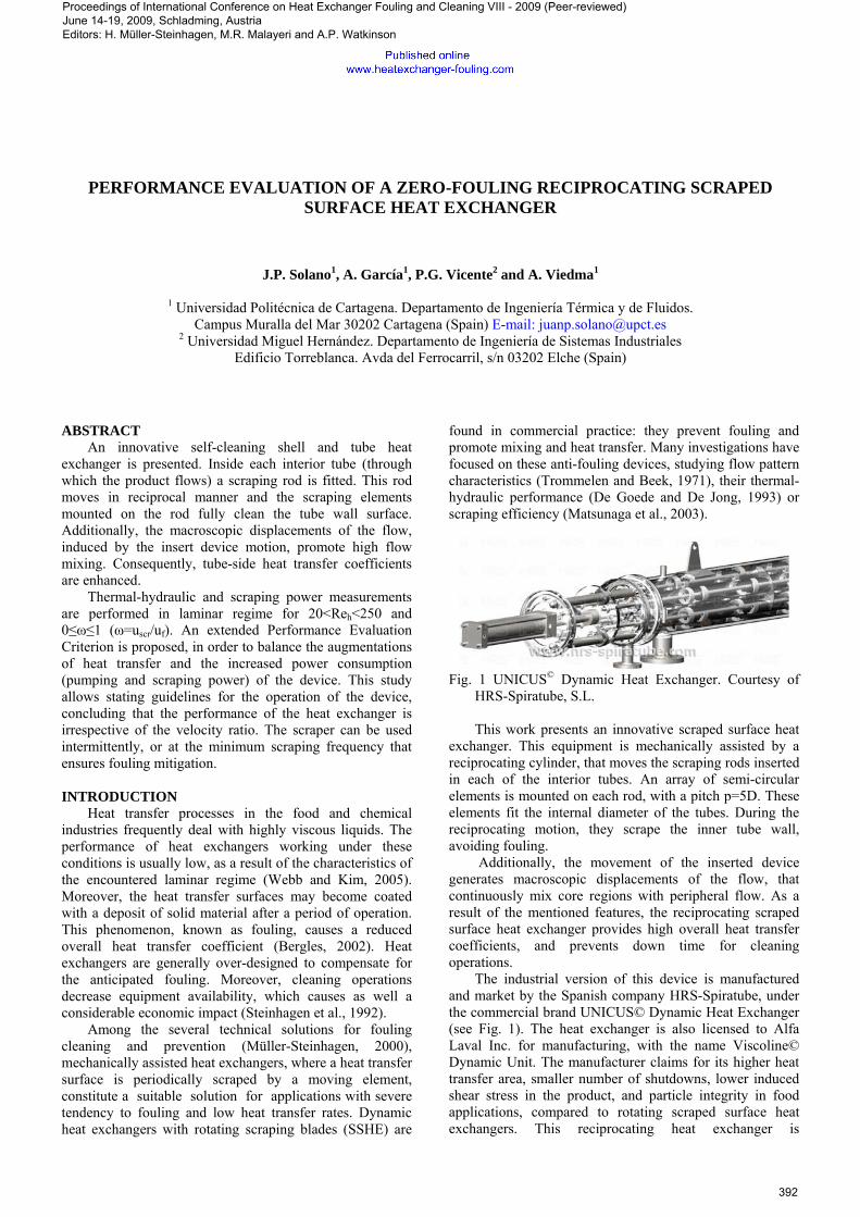
Fig. 1 UNICUS© Dynamic Heat Exchanger. Courtesy of HRS-Spiratube, S.L.
This work presents an innovative scraped surface heat
exchanger. This equipment is mechanically assisted by a reciprocating cylinder, that moves the scraping rods inserted in each of the interior tubes. An array of semi-circular elements is mounted on each rod, with a pitch p=5D. These elements fit the internal diameter of the tubes. During the reciprocating motion, they scrape the inner tube wall, avoiding fouling.
Additionally, the movement of the inserted device generates macroscopic displacements of the flow, that continuously mix core regions with peripheral flow. As a result of the mentioned features, the reciprocating scraped surface heat exchanger provides high overall heat transfer coefficients, and prevents down time for cleaning operations.
The industrial version of this device is manufactured and market by the Spanish company HRS-Spiratube, under the commercial brand UNICUS© Dynamic Heat Exchanger (see Fig. 1). The heat exchanger is also licensed to Alfa Laval Inc. for manufacturing, with the name Viscoline© Dynamic Unit. The manufacturer claims for its higher heat transfer area, smaller number of shutdowns, lower induced shear stress in the product, and particle integrity in food applications, compared to rotating scraped surface heat exchangers. This reciprocating heat exchanger is
Proceedings of International Conference on Heat Exchanger Fouling and Cleaning VIII - 2009 (Peer-reviewed) June 14-19, 2009, Schladming, Austria Editors: H. Müller-Steinhagen, M.R. Malayeri and A.P. Watkinson
392
progressively being introduced in the food industry, wastewater treatment processes, production of second-generation biofuels, etc. It founds its most practical application under severe fouling tendency, where obstruction of the tubes occur in few hours if no cleaning strategies are adopted.
Depending on the severity of the fouling phenomenon, the scraper can be either activated intermittently, or move continuously in a wide range of scraping velocities. This variety of operating conditions yields to different heat transfer and pressure drop characteristics (Solano et al., 2006), as well as scraping power consumption. A characterization of the heat exchanger performance is necessary to assess the relation between heat transfer enhancement and augmentation of power consumption (pumping and scraping) in the heat exchanger, provided that tube walls keep clean in all the regimes.
To accomplish with this requirement, a thourough experimental work has been developed. Pressure drop, scraping power and heat transfer measurements are obtained in laminar regime for Reynolds numbers 20<Reh<250 and velocity ratios 0≤ω≤1 (ω=uscr/uf).
Performance Evaluation Criterion R3 (Bergles et al., 1974) has been extended to account for the scraping power consumption. This evaluation allows stating the heat exchange increase obtained when a scraper is introduced in a tubular heat exchanger, while keeping constant the heat transfer area and global power consumption. The presence of fouling in the smooth tubes of the heat exchanger have also been considered in the formulation of this criterion. EXPERIMENTAL SET-UP
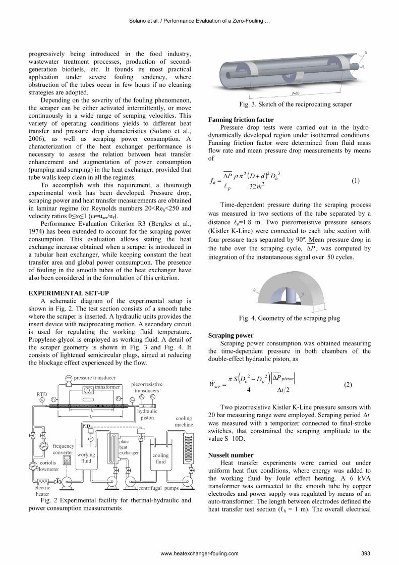
A schematic diagram of the experimental setup is shown in Fig. 2. The test section consists of a smooth tube where the scraper is inserted. A hydraulic units provides the insert device with reciprocating motion. A secondary circuit is used for regulating the working fluid temperature. Propylene-glycol is employed as working fluid. A detail of the scraper geometry is shown in Fig. 3 and Fig. 4. It consists of lightened semicircular plugs, aimed at reducing the blockage effect experienced by the flow.
frequencyconverter
coriolisflowmeter
electricheater
centrifugal pumps
coolingfluid
workingfluid
plateheatexchanger
transformer
pressure transducer
hydraulicpiston
PID
RTD
piezorresistivetransducers
coolingmachine
Fig. 2 Experimental facility for thermal-hydraulic and
power consumption measurements
Fig. 3. Sketch of the reciprocating scraper
Fanning friction factor
Pressure drop tests were carried out in the hydro-dynamically developed region under isothermal conditions. Fanning friction factor were determined from fluid mass flow rate and mean pressure drop measurements by means of
( )
2
322
32mDdDPf h
ph
&l
+Δ=
πρ (1)
Time-dependent pressure during the scraping process
was measured in two sections of the tube separated by a distance ℓp=1.8 m. Two piezorresistive pressure sensors (Kistler K-Line) were connected to each tube section with four pressure taps separated by 90º. Mean pressure drop in the tube over the scraping cycle, PΔ , was computed by integration of the instantaneous signal over 50 cycles.
Fig. 4. Geometry of the scraping plug
Scraping power Scraping power consumption was obtained measuring the time-dependent pressure in both chambers of the double-effect hydraulic piston, as
( )24
22
t
PDDSW
pistonpcscr Δ
Δ−=π& (2)
Two pizorresistive Kistler K-Line pressure sensors with
20 bar measuring range were employed. Scraping period tΔ was measured with a temporizer connected to final-stroke switches, that constrained the scraping amplitude to the value S=10D. Nusselt number
Heat transfer experiments were carried out under uniform heat flux conditions, where energy was added to the working fluid by Joule effect heating. A 6 kVA transformer was connected to the smooth tube by copper electrodes and power supply was regulated by means of an auto-transformer. The length between electrodes defined the heat transfer test section (ℓh = 1 m). The overall electrical
Solano et al. / Performance Evaluation of a Zero-Fouling …
www.heatexchanger-fouling.com 393
power added to the heating section, Q, was calculated by measuring the voltage between electrodes (0-15 V) and the electrical current (0-600A).
Fluid inlet and outlet temperatures, Tin and Tout were measured by submerged type resistance temperature detectors (RTDs). Since heat was added uniformly along the tube length, the bulk temperature of the fluid at the measuring section, Tb(xp), was calculated by considering a linear variation with the axial direction. Average outside surface temperature of the wall was measured at six different axial positions along a scraper pitch, located at 30 diameters from the upstream electrode, that ensure fully developed flow. The outer wall temperature at each axial position was calculated by averaging the temperatures measured with eight surface type RTDs peripherally spaced by every 45º at each axial position. Inner wall temperature Twi was obtained with the numerical solution of the radial, 1D heat conduction across the tube and insulation. The local Nusselt number is calculated by means of
)(,pbwi
hxh xTT
qk
DNu
−
′′= (3)
101 102
10-1
100
Reh
fh
ω=0 ω=0.1
ω=1 ω=0.5
smooth pipe
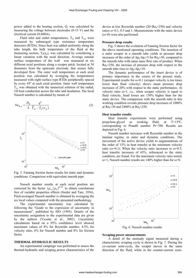
Fig. 5. Fanning friction factor results for static and dynamic conditions. Comparison with equivalent smooth pipe Nusselt number results at each axial position are corrected by the factor 14.0)( bw μμ to obtain correlations free of variable properties effects (Sieder and Tate, 1936). Pitch-averaged Nusselt number is obtained by averaging the six local values computed with the presented methodology.
The experimental uncertainty was calculated by following the “Guide to the expression of uncertainty in measurement”, published by ISO (1995). Details of the uncertainty assignation to the experimental data are given by the authors (Vicente et al., 2002). Uncertainty calculations based on a 95% confidence level showed maximum values of 4% for Reynolds number, 4.5% for velocity ratio, 6% for Nusselt number and 8% for friction factor. THERMAL-HYDRAULIC RESULTS An experimental campaign was performed to assess the thermal-hydraulic and scraping power characteristics of the
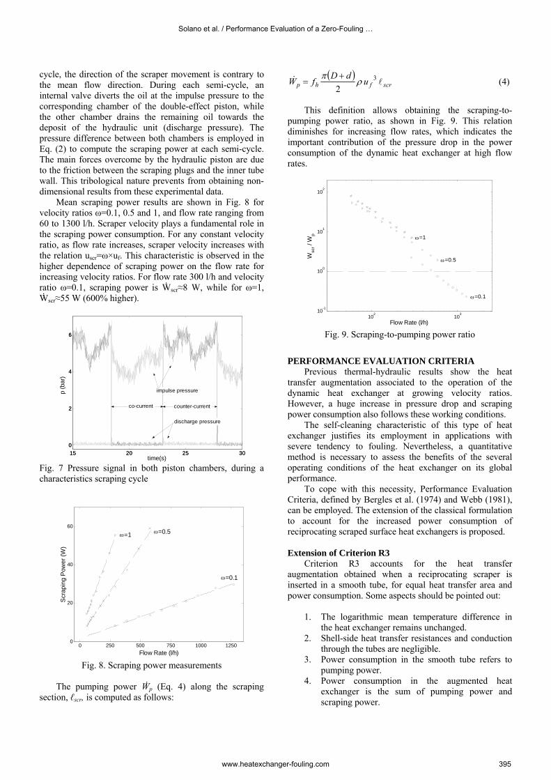
device at low Reynolds number (20<Reh<250) and velocity ratios ω=0.1, 0.5 and 1. Measurements with the static device (ω=0) were also performed. Pressure drop results Fig. 5 shows the evolution of Fanning friction factor for the above mentioned operating conditions. The insertion of a static scraper in a smooth tube yields to pressure drop increases of the order of Δpa/Δps≈5 for Reh≈30, compared to the smooth tube with same mass flow rate of product. When Reh≈250, the increase of pressure drop with respect to the smooth tube rises to Δpa/Δps≈10. The dynamic performance of the insert device is of primary importance in the course of the present study. Experimental results for ω=0.1 (scraper velocity is ten times lower than fluid velocity) shows mean pressure drop increases of 20% with respect to the static performance. At velocity ratio ω=1, i.e., when scraper velocity is equal to fluid velocity, head losses are 150% higher than for the static device. The comparison with the smooth tube in this working condition reveals pressure drop increases of 1000% at Reh≈30 and 2400% at Reh≈250. Heat transfer results Heat transfer experiments were performed using propylene-glycol as working fluid, at T=15ºC, corresponding to Prandtl number Pr=700. Results are depicted in Fig. 6. Nusselt number increases with Reynolds number in the laminar regime, in static and dynamic conditions. The movement of the active device yields to augmentations of the order of 15% in heat transfer at the minimum velocity ratio (ω=0.1). When the velocity ratio increases to ω=0.5, heat transfer increases of 65%, referenced to the static condition, are found. For the maximum velocity ratio tested, ω=1, Nusselt number results are 140% higher than for ω=0.
101 102
101
102
Reh
Nuh
ω=0 ω=0.1 ω=0.5
ω=1
Fig. 6. Nusselt number results
Scraping power measurements A detail of the unsteady signal measured during a characteristic scraping cycle is shown in Fig. 7. During the co-current semi-cycle, the scraper moves in the same direction of the fluid, while in the counter-current semi-
Heat Exchanger Fouling and Cleaning VIII – 2009
www.heatexchanger-fouling.com 394
cycle, the direction of the scraper movement is contrary to the mean flow direction. During each semi-cycle, an internal valve diverts the oil at the impulse pressure to the corresponding chamber of the double-effect piston, while the other chamber drains the remaining oil towards the deposit of the hydraulic unit (discharge pressure). The pressure difference between both chambers is employed in Eq. (2) to compute the scraping power at each semi-cycle. The main forces overcome by the hydraulic piston are due to the friction between the scraping plugs and the inner tube wall. This tribological nature prevents from obtaining non-dimensional results from these experimental data.
Mean scraping power results are shown in Fig. 8 for velocity ratios ω=0.1, 0.5 and 1, and flow rate ranging from 60 to 1300 l/h. Scraper velocity plays a fundamental role in the scraping power consumption. For any constant velocity ratio, as flow rate increases, scraper velocity increases with the relation uscr=ω×uf. This characteristic is observed in the higher dependence of scraping power on the flow rate for increasing velocity ratios. For flow rate 300 l/h and velocity ratio ω=0.1, scraping power is Ẇscr≈8 W, while for ω=1, Ẇscr≈55 W (600% higher).
15 20 25 300
2
4
6
time(s)
p (b
ar)
pcc(t)peq(t)
15 20 25 300
2
4
6
discharge pressure
impulse pressure
co-current counter-current
Fig. 7 Pressure signal in both piston chambers, during a characteristics scraping cycle
0 250 500 750 1000 12500
20
40
60
Flow Rate (l/h)
Scr
apin
g P
ower
(W)
ω=0.1
ω=0.5 ω=1
Fig. 8. Scraping power measurements
The pumping power Ẇp (Eq. 4) along the scraping
section, ℓscr, is computed as follows:
( )scrfhp udDfW l& 3
2ρ
π += (4)
This definition allows obtaining the scraping-to-
pumping power ratio, as shown in Fig. 9. This relation diminishes for increasing flow rates, which indicates the important contribution of the pressure drop in the power consumption of the dynamic heat exchanger at high flow rates.
102
103
10-1
100
101
102
Flow Rate (l/h)
Wsc
r / W
p
ω=0.1
ω=0.5
ω=1
Fig. 9. Scraping-to-pumping power ratio
PERFORMANCE EVALUATION CRITERIA Previous thermal-hydraulic results show the heat transfer augmentation associated to the operation of the dynamic heat exchanger at growing velocity ratios. However, a huge increase in pressure drop and scraping power consumption also follows these working conditions. The self-cleaning characteristic of this type of heat exchanger justifies its employment in applications with severe tendency to fouling. Nevertheless, a quantitative method is necessary to assess the benefits of the several operating conditions of the heat exchanger on its global performance.
To cope with this necessity, Performance Evaluation Criteria, defined by Bergles et al. (1974) and Webb (1981), can be employed. The extension of the classical formulation to account for the increased power consumption of reciprocating scraped surface heat exchangers is proposed. Extension of Criterion R3
Criterion R3 accounts for the heat transfer augmentation obtained when a reciprocating scraper is inserted in a smooth tube, for equal heat transfer area and power consumption. Some aspects should be pointed out:
1. The logarithmic mean temperature difference in
the heat exchanger remains unchanged. 2. Shell-side heat transfer resistances and conduction
through the tubes are negligible. 3. Power consumption in the smooth tube refers to
pumping power. 4. Power consumption in the augmented heat
exchanger is the sum of pumping power and scraping power.
Solano et al. / Performance Evaluation of a Zero-Fouling …
www.heatexchanger-fouling.com 395
According to the previous items, R3 factor can be formulated as
TWNhs
ha
DD
NuNu
RΔ
⎟⎟⎠
⎞⎜⎜⎝
⎛=
,,,
,3&l
(5)
Eq. 5 relates the heat transfer coefficient in the tube
side of the reciprocating scraped surface heat exchanger with the heat transfer coefficient in the equivalent smooth pipe. However, a further extension of this formulation can be done if the existence of a fouling resistance (Rf) in the smooth tube is considered:
i
f
ises AR
AhAU+=
11 (6)
Being R3=Ua/Us, substitution of Eq. 6 yields:
TWNh
fs
s
ha
DkRNuD
NuNu
RΔ
⎟⎟⎠
⎞⎜⎜⎝
⎛ +=
,,,
,3&l
(7)
In Eqs. (5) and (7), Nus is the Nusselt number in the smooth pipe evaluated at the equivalent Reynolds number Res, which is subjected to the constraint of equal power consumption in both smooth and augmented tubes:
( )⎟⎟⎠
⎞⎜⎜⎝
⎛+
+= scr
scrscr
hhaha
ss WD
DdDDf
f&
ll 3
22
3
2
,3
,3 2Re1Re
μρ
π (8)
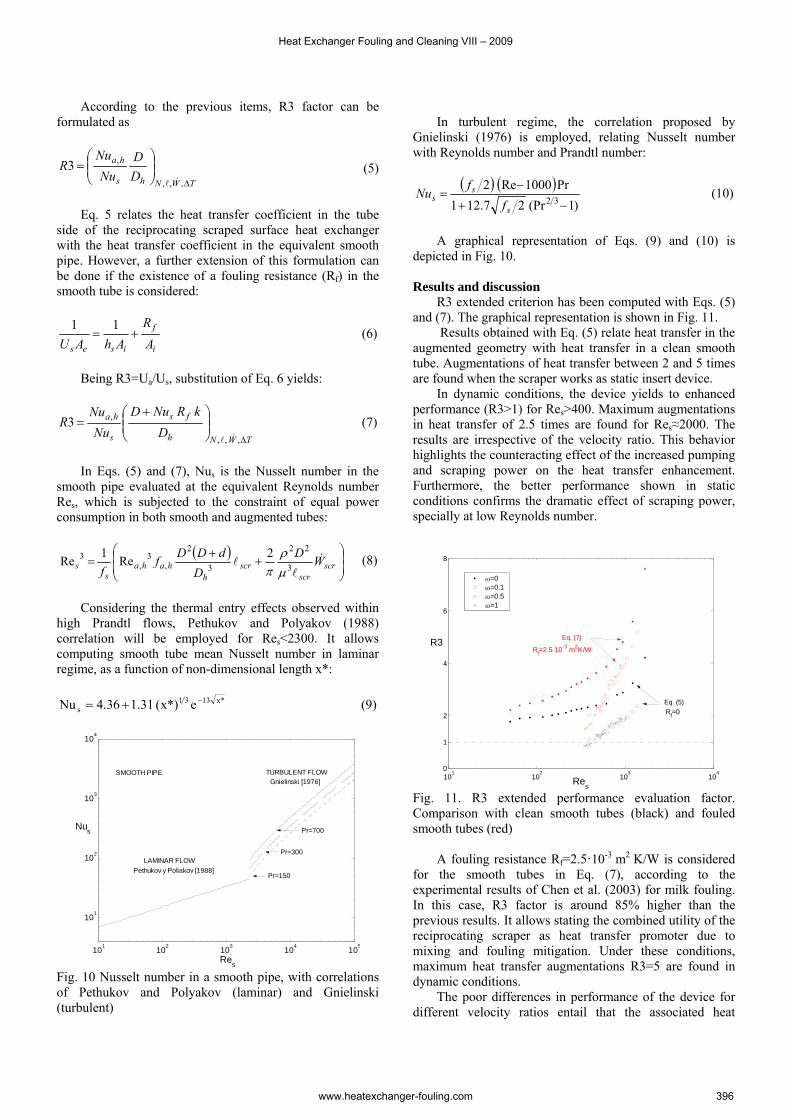
Considering the thermal entry effects observed within high Prandtl flows, Pethukov and Polyakov (1988) correlation will be employed for Res<2300. It allows computing smooth tube mean Nusselt number in laminar regime, as a function of non-dimensional length x*:
*x1331s e*)x(31.136.4Nu −+= (9)
101 102 103 104 105
101
102
103
104
Res
Nus
Pr=150
Pr=300
Pr=700
LAMINAR FLOWPethukov y Poliakov [1988]
TURBULENT FLOWGnielinski [1976]
SMOOTH PIPE
Fig. 10 Nusselt number in a smooth pipe, with correlations of Pethukov and Polyakov (laminar) and Gnielinski (turbulent)
In turbulent regime, the correlation proposed by
Gnielinski (1976) is employed, relating Nusselt number with Reynolds number and Prandtl number:
( ) ( ))1(Pr27.121
Pr1000Re232 −+
−=
s
ss f
fNu (10)
A graphical representation of Eqs. (9) and (10) is
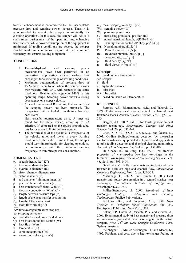
depicted in Fig. 10. Results and discussion R3 extended criterion has been computed with Eqs. (5) and (7). The graphical representation is shown in Fig. 11.
Results obtained with Eq. (5) relate heat transfer in the augmented geometry with heat transfer in a clean smooth tube. Augmentations of heat transfer between 2 and 5 times are found when the scraper works as static insert device.
In dynamic conditions, the device yields to enhanced performance (R3>1) for Res>400. Maximum augmentations in heat transfer of 2.5 times are found for Res≈2000. The results are irrespective of the velocity ratio. This behavior highlights the counteracting effect of the increased pumping and scraping power on the heat transfer enhancement. Furthermore, the better performance shown in static conditions confirms the dramatic effect of scraping power, specially at low Reynolds number.
101
102
103
104
0
1
2
4
6
8
Res
R3
ω=0ω=0.1ω=0.5ω=1
Eq. (7)
Rf=2.5·10-3 m2K/W
Eq. (5) Rf=0
Fig. 11. R3 extended performance evaluation factor. Comparison with clean smooth tubes (black) and fouled smooth tubes (red)
A fouling resistance Rf=2.5·10-3 m2 K/W is considered for the smooth tubes in Eq. (7), according to the experimental results of Chen et al. (2003) for milk fouling. In this case, R3 factor is around 85% higher than the previous results. It allows stating the combined utility of the reciprocating scraper as heat transfer promoter due to mixing and fouling mitigation. Under these conditions, maximum heat transfer augmentations R3=5 are found in dynamic conditions.
The poor differences in performance of the device for different velocity ratios entail that the associated heat
Heat Exchanger Fouling and Cleaning VIII – 2009
www.heatexchanger-fouling.com 396
transfer enhancement is counteracted by the unacceptable pressure drop and scraping power increase. Thus, it is recommended to activate the scraper intermittently for cleaning operations. In this case, the scraper will act as a static mixer during most of the operating time, enhancing heat transfer, while power consumption of the equipment is minimized. If fouling conditions are severe, the scraper should work in continuous regime at the minimum frequency that ensures fouling mitigation. CONCLUSIONS
1. Thermal-hydraulic and scraping power measurements have been performed in an innovative reciprocating scraped surface heat exchanger, for a wide range of working conditions.
2. Maximum augmentations of pressure drop of 150% have been found when the scraper moves with velocity ratio ω=1, with respect to the static conditions. Heat transfer augments 140% in this operating range. Scraping power shows a strong dependency on scraper velocity.
3. A new formulation of R3 criteria, that accounts for the scraping power, has been proposed. The comparison with a fouled smooth tube has also been stated.
4. Heat transfer augmentations up to 5 times are found for the static device, according to R3 criterion. If compared to the fouled smooth tube, this factor arises to 8, for laminar regime.
5. The performance of the dynamic is irrespective of the velocity ratio, and lower in every working conditions to the static results. Thus, the scraper should work intermittenly, for cleaning operations, or continuously with the minimum scraping frequency, to minimize power consumption.
NOMENCLATURE cp specific heat (J kg-1 K-1) D tube inner diameter (m) Dh hydraulic diameter (m) Dc piston chamber diameter (m) Dp piston diameter (m) d rod diameter (minimum inner) (m) p pitch of the insert devices (m) h heat transfer coefficient (W m-2K-1) k thermal conductivity (W m-1K-1) ℓp length between pressure taps (m) ℓh length of the heat transfer section (m) ℓscr length of the scraper (m) m& mass flow rate (kg s-1)
PΔ time averaged pressure drop (Pa) tΔ scraping period (s)
Q overall electrical power added (W) Q1 heat losses in the test section (W) q” heat flux (W m-2) T temperature (K) S scraping amplitude (m) uf mean fluid velocity, (m/s)
uscr mean scraping velocity, (m/s) Ẇscr scraping power (W) Ẇp pumping power (W) xp measuring point axial position (m) x* non-dimensional length, x/(D·Re·Pr) [-] fh Fanning friction factor, ΔP Dh/(2 ρuf
2 lp) [-] Nuh Nusselt number, hDh/k [-] Pr Prandtl number, μcp/k [-] Reh Reynolds number, ρufDh/ μ [-] ω velocity ratio, uscr/uf [-] ρ fluid density (kg m3) μ fluid viscosity (kg m-1 s-1) Subscripts b based on bulk temperature scr scraper f fluid c hydraulic chamber in tube inlet out tube outlet w based on inside wall temperature REFERENCES
Bergles, A.E., Blumenkrantz, A.R., and Taborek, J., 1974, Performance evaluation criteria for enhanced heat transfer surfaces, Journal of Heat Transfer, Vol. 2, pp. 239–243.
Bergles, A.E., 2002, ExHFT for fourth generation heat transfer technology, Experimental Thermal and Fluid Science, Vol. 26, pp. 335-344.
Chen, X.D., Li, D.X.Y., Lin, S.X.Q., and Özkan, N., 2003, On-line fouling/cleaning detection by measuring electric resistance- equipment development and application to milk fouling detection and chemical cleaning monitoring, Journal of Food Engineering, Vol. 61, pp. 181-189.
De Goede, R., De Jong, E.J., 1993, Heat transfer properties of a scraped-surface heat exchanger in the turbulent flow regime, Chemical Engineering Science, Vol. 48, No. 8, pp.1393-1404.
Gnielinski, V., 1976, New equations for heat and mass transfer in turbulent pipe and channel flow, International Chemical Engineering, Vol. 16, pp. 359-368.
Matsunaga, T., Roh, M. and Kamota, T., 2003, Heat transfer and power consumption in a scraped surface heat exchanger, International Institute of Refrigeration, Washington D.C., USA.
Müller-Steinhagen, H., 2000, Handbook of Heat Exchanger Fouling – Mitigation and Cleaning Technologies, Publico Publications.
Petukhov, B.S., and Polyakov, A.F., 1988, Heat Transfer in Turbulent Mixed Convection, first ed., Hemisphere Publishing, New York, USA.
Solano, J.P., García, A., Vicente, P.G., and Viedma, A., 2006, Experimental study of heat transfer and pressure drop in mechanically-assisted heat exchangers with active scrapers, Proc. 13th Int. Heat Transfer Conference 2006, Sydney, Australia.
Steinhagen, R., Müller-Steinhagen, H., and Maani, K., 1992, Problems and costs due to heat exchanger fouling in
Solano et al. / Performance Evaluation of a Zero-Fouling …
www.heatexchanger-fouling.com 397
New Zealand industries, Heat Transfer Engineering, Vol. 14, pp. 19-30.
Trommelen, A.M., and Beek, W.J., 1971, Flow phenomena in a scraped surface heat exchanger, Chemical Engineering Science, Vol. 26, pp. 1933-1941.
Wang, W., Walt, J.H., McCarthy, K.L., Flow profiles of power law fluids in scraped surface heat exchanger geometry using MRI, Journal of Food Process Engineering, Vol. 22, pp 11-27, 1999.
Webb, R.L., and Kim, N., 2005, Principles of Enhanced Heat Transfer, Taylor and Francis, New York, USA
Webb, R.L., 1981, Performance evaluation criteria for used of enhanced heat transfer surfaces in heat exchanger design, International Journal of Heat and Mass Transfer, Vol. 24, pp. 715-726
Sieder, E.N., y Tate, E.G., Heat transfer and pressure drop of liquids in tubes, Ind. Eng. Chem., Vol. 28, p. 1429. 1936.
ISO, 1995, Guide to the Expression of Uncertainty in Measurement, first ed., International Organization for Standardization, Switzerland.
Vicente, P.G., García, A., Viedma, A., 2002, Experimental study of mixed convection and pressure drop in helically dimpled tubes for laminar and transition flow, International Journal of Heat and Mass Transfer, Vol. 45, pp. 5091–5105.
Heat Exchanger Fouling and Cleaning VIII – 2009
www.heatexchanger-fouling.com 398