Embed Size (px)
DESCRIPTION
Multiple Altimeter Beam Experimental Lidar (MABEL). An Overview. Why do we need MABEL?. - PowerPoint PPT Presentation
Citation preview
1
Multiple Altimeter Beam Experimental Lidar (MABEL)
An Overview
2Why do we need MABEL?
ICESat-2 is utilizing a relatively new approach for surface altimetry, with multiple transmit/receive beams to permit measurement of cross-track slope. This new approach relies on using high rep-rate, low pulse energy laser(s) and photon-counting detection.
It would be good if we had high-altitude airborne measurements to conclusively demonstrate the measurement concept.
Normally we have a demonstrator instrument and measurements before mission approval. Not so in the case of ICESat-2. At this point, data from MABEL is critical for model validation and algorithm development.
Comfort level for science, engineering, and management alike will be improved with demonstration measurements from MABEL.
3
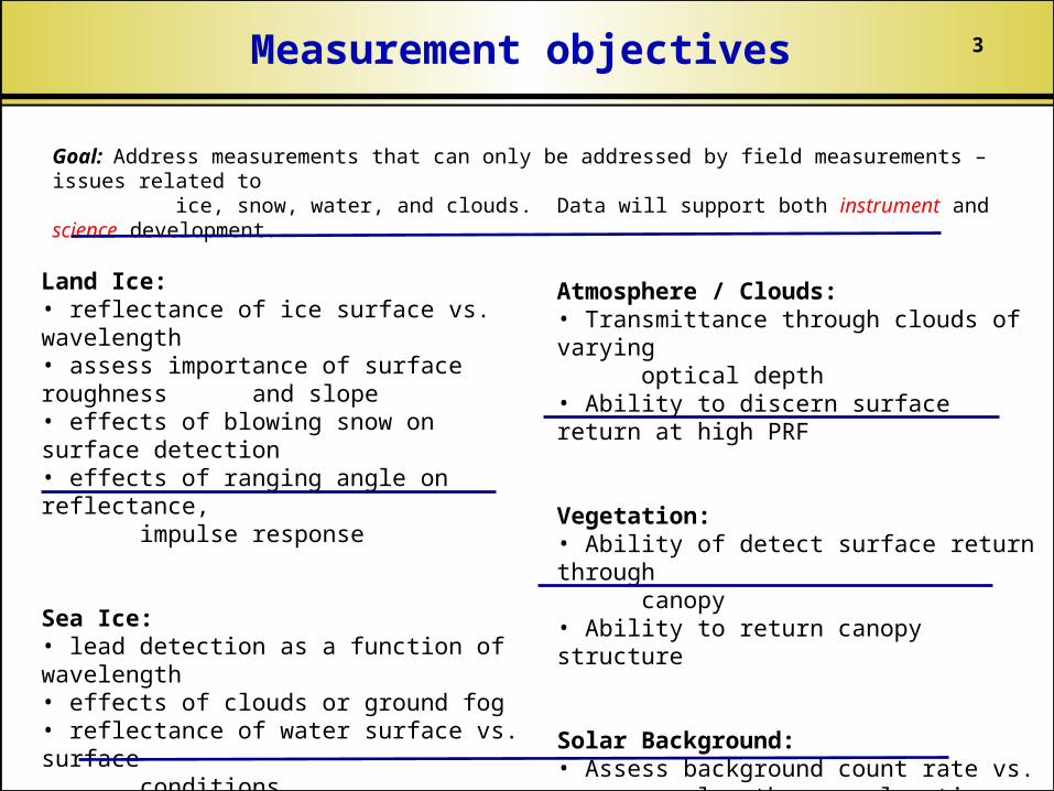
Goal: Address measurements that can only be addressed by field measurements – issues related to ice, snow, water, and clouds. Data will support both instrument and science development.
Land Ice:• reflectance of ice surface vs. wavelength• assess importance of surface roughness and slope• effects of blowing snow on surface detection• effects of ranging angle on reflectance, impulse response
Sea Ice:• lead detection as a function of wavelength• effects of clouds or ground fog• reflectance of water surface vs. surface conditions
Atmosphere / Clouds:• Transmittance through clouds of varying optical depth• Ability to discern surface return at high PRF
Vegetation:• Ability of detect surface return through canopy• Ability to return canopy structure
Solar Background:• Assess background count rate vs. wavelength, sun elevation, etc..
Measurement objectives
4Flexibilities required
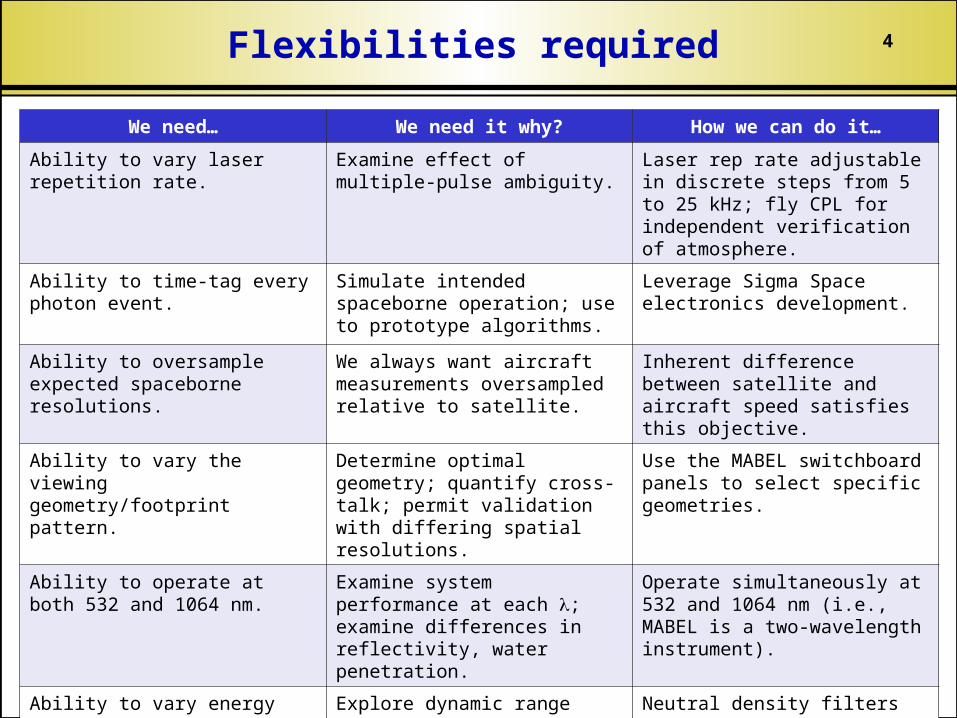
We need… We need it why? How we can do it…
Ability to vary laser repetition rate.
Examine effect of multiple-pulse ambiguity.
Laser rep rate adjustable in discrete steps from 5 to 25 kHz; fly CPL for independent verification of atmosphere.
Ability to time-tag every photon event.
Simulate intended spaceborne operation; use to prototype algorithms.
Leverage Sigma Space electronics development.
Ability to oversample expected spaceborne resolutions.
We always want aircraft measurements oversampled relative to satellite.
Inherent difference between satellite and aircraft speed satisfies this objective.
Ability to vary the viewing geometry/footprint pattern.
Determine optimal geometry; quantify cross-talk; permit validation with differing spatial resolutions.
Use the MABEL switchboard panels to select specific geometries.
Ability to operate at both 532 and 1064 nm.
Examine system performance at each ; examine differences in reflectivity, water penetration.
Operate simultaneously at 532 and 1064 nm (i.e., MABEL is a two-wavelength instrument).
Ability to vary energy level for each footprint.
Explore dynamic range trade space; inform satellite design.
Neutral density filters in transmit/receive path emulate the satellite.
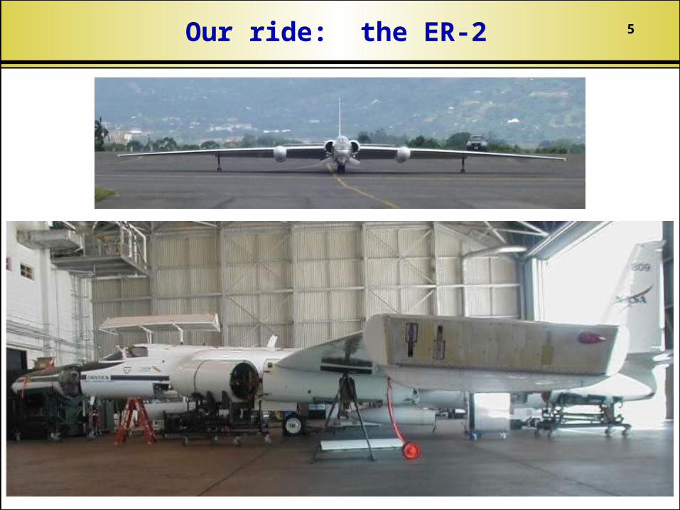
5Our ride: the ER-2
6
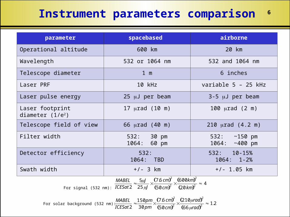
parameter spacebased airborne
Operational altitude 600 km 20 km
Wavelength 532 or 1064 nm 532 and 1064 nm
Telescope diameter 1 m 6 inches
Laser PRF 10 kHz variable 5 – 25 kHz
Laser pulse energy 25 J per beam 3-5 J per beam
Laser footprint diameter (1/e2)
17 rad (10 m) 100 rad (2 m)
Telescope field of view 66 rad (40 m) 210 rad (4.2 m)
Filter width 532: 30 pm1064: 60 pm
532: ~150 pm1064: ~400 pm
Detector efficiency 532: 1064: TBD
532: 10-15% 1064: 1-2%
Swath width +/- 3 km +/- 1.05 km
Instrument parameters comparison
MABEL
ICESat2
5J25 J
7.6 cm 2
50 cm 2 600 km 2
20 km 2 4For signal (532 nm):
For solar background (532 nm):
MABEL
ICESat2
150 pm
30 pm
7.6 cm 2
50 cm 2 210 rad 2
66 rad 2 1.2
7
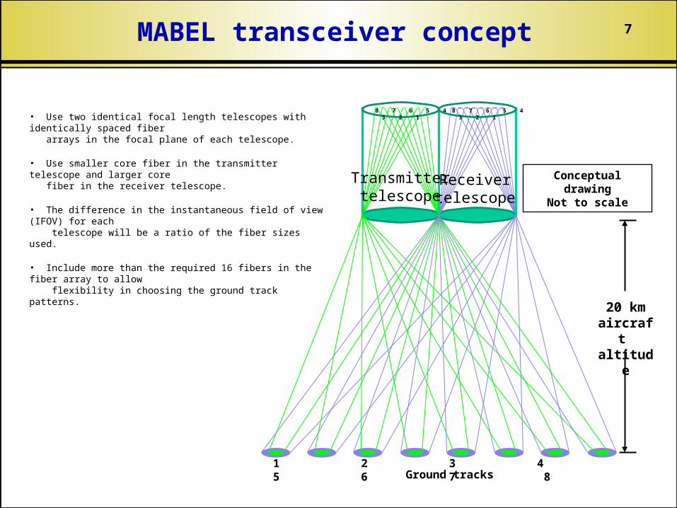
• Use two identical focal length telescopes with identically spaced fiber arrays in the focal plane of each telescope.
• Use smaller core fiber in the transmitter telescope and larger core fiber in the receiver telescope.
• The difference in the instantaneous field of view (IFOV) for each telescope will be a ratio of the fiber sizes used.
• Include more than the required 16 fibers in the fiber array to allow flexibility in choosing the ground track patterns.
Conceptual drawing
Not to scale
20 km aircraft altitud
e
Ground tracks
Receivertelescope
Transmittertelescope
1 2 3 4 5 6 7 8
8 7 6 5 4 3 2 1
8 7 6 5 4 3 2 1
MABEL transceiver concept
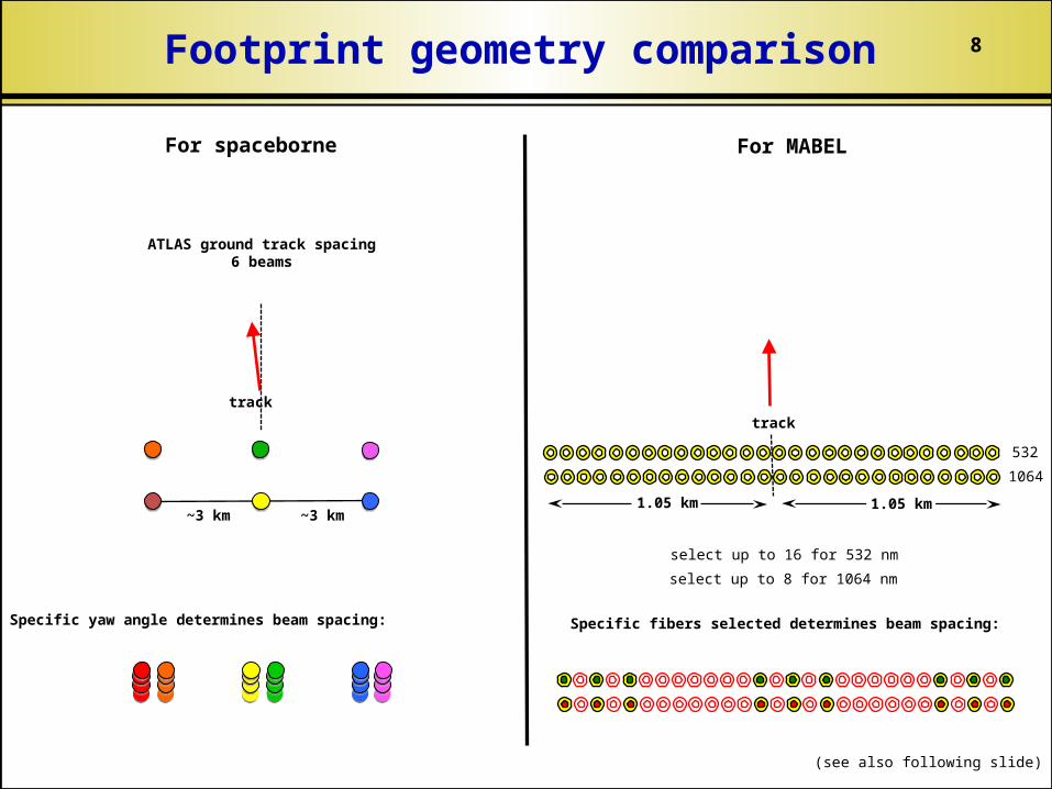
8Footprint geometry comparison
For spaceborne For MABEL
select up to 16 for 532 nm
select up to 8 for 1064 nm
Specific fibers selected determines beam spacing:
track
532
1064
1.05 km1.05 km
(see also following slide)
Specific yaw angle determines beam spacing:
~3 km~3 km
ATLAS ground track spacing6 beams
track
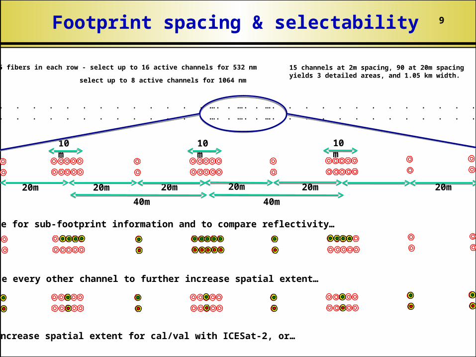
9Footprint spacing & selectability
sample for sub-footprint information and to compare reflectivity…
or use every other channel to further increase spatial extent…
or increase spatial extent for cal/val with ICESat-2, or…
10m
20m
40m 40m
10m
10m
20m20m 20m20m20m
105 fibers in each row - select up to 16 active channels for 532 nm
select up to 8 active channels for 1064 nm
. . . . . . . . . . . . . . . . . . . …. . …. . …. . . . . . . . . . . . . . . . . . . .
. . . . . . . . . . . . . . . . . . . …. . …. . …. . . . . . . . . . . . . . . . . . . .
15 channels at 2m spacing, 90 at 20m spacingyields 3 detailed areas, and 1.05 km width.
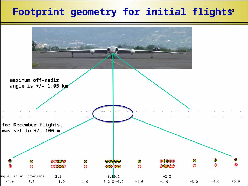
10Footprint geometry for initial flights
maximum off-nadirangle is +/- 1.05 km
for December flights,was set to +/- 100 m
. . . . . . . . . . . . . . . . . . . …. . …. . …. . . . . . . . . . . . . . . . . . . .
. . . . . . . . . . . . . . . . . . . …. . …. . …. . . . . . . . . . . . . . . . . . . .
0
+0.1
+0.2 +1.0 +3.0+1.9
+2.0-0.1
-0.2-1.0-1.9
-2.0
-3.0-4.0 +4.0 +5.0
angle, in milliradians
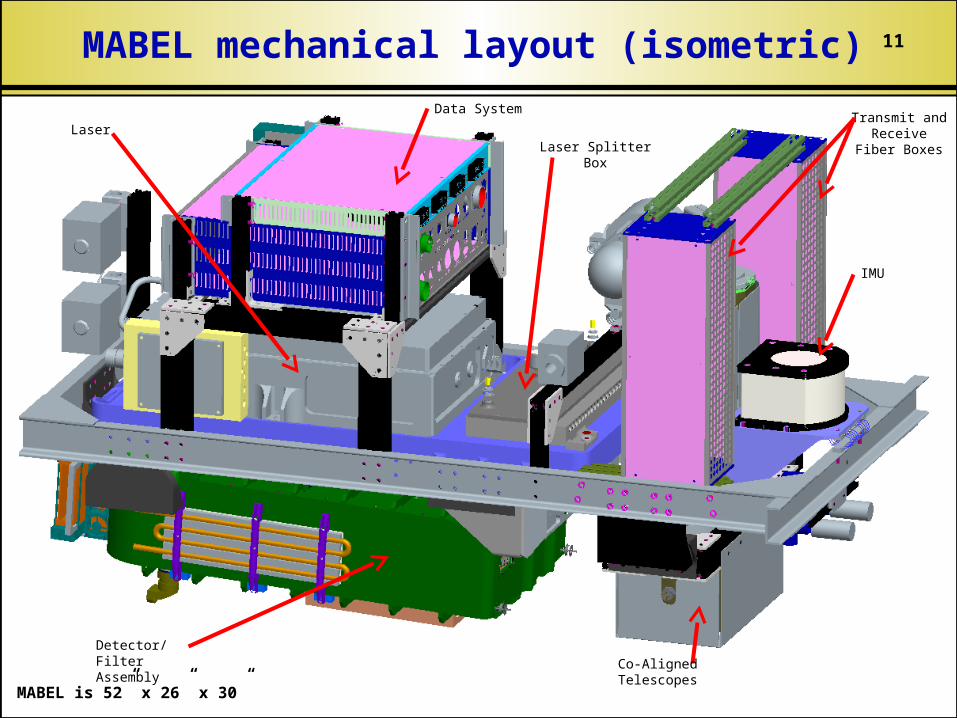
11MABEL mechanical layout (isometric)
Data SystemTransmit and Receive Fiber
Boxes
LaserLaser Splitter Box
Co-Aligned Telescopes
Detector/Filter Assembly
IMU
MABEL is 52” x 26” x 30”
12
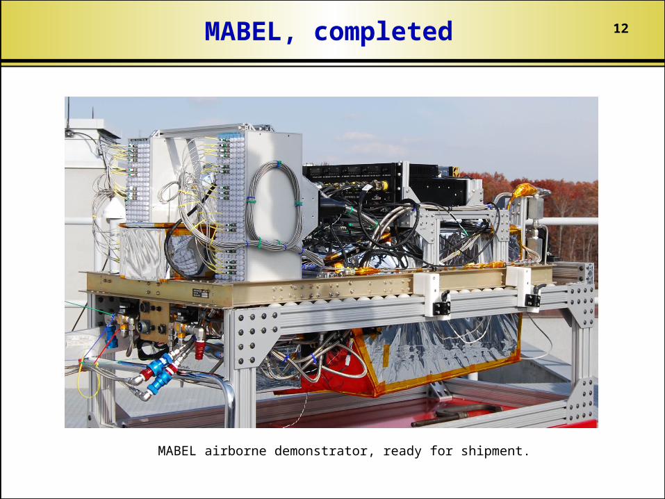
MABEL airborne demonstrator, ready for shipment.
MABEL, completed
13
0
20
10
15
5
Alt
itu
de (
km)
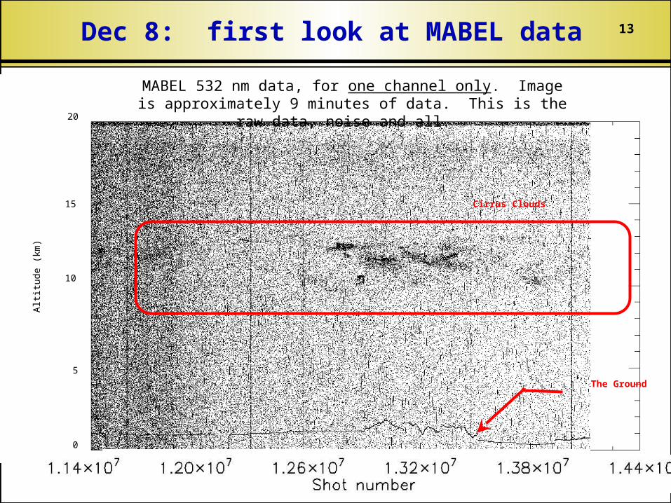
The Ground
Cirrus Clouds
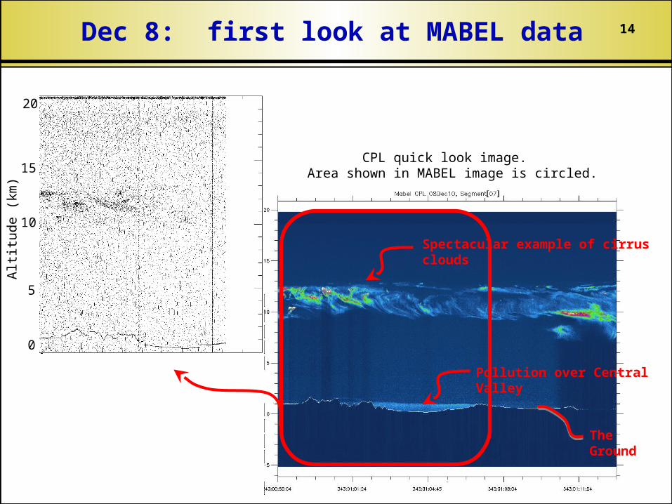
MABEL 532 nm data, for one channel only. Image is approximately 9 minutes of data. This is the raw data,
noise and all.
Dec 8: first look at MABEL data
14
CPL quick look image. Area shown in MABEL image is circled.
0
20
10
15
5
Alt
itude (
km
)
Spectacular example of cirrus clouds
Pollution over Central Valley
The Ground
Dec 8: first look at MABEL data
15
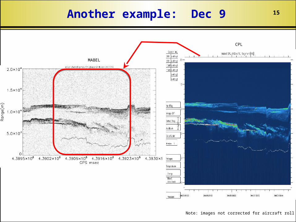
MABEL
CPL
Another example: Dec 9
Note: images not corrected for aircraft roll
16
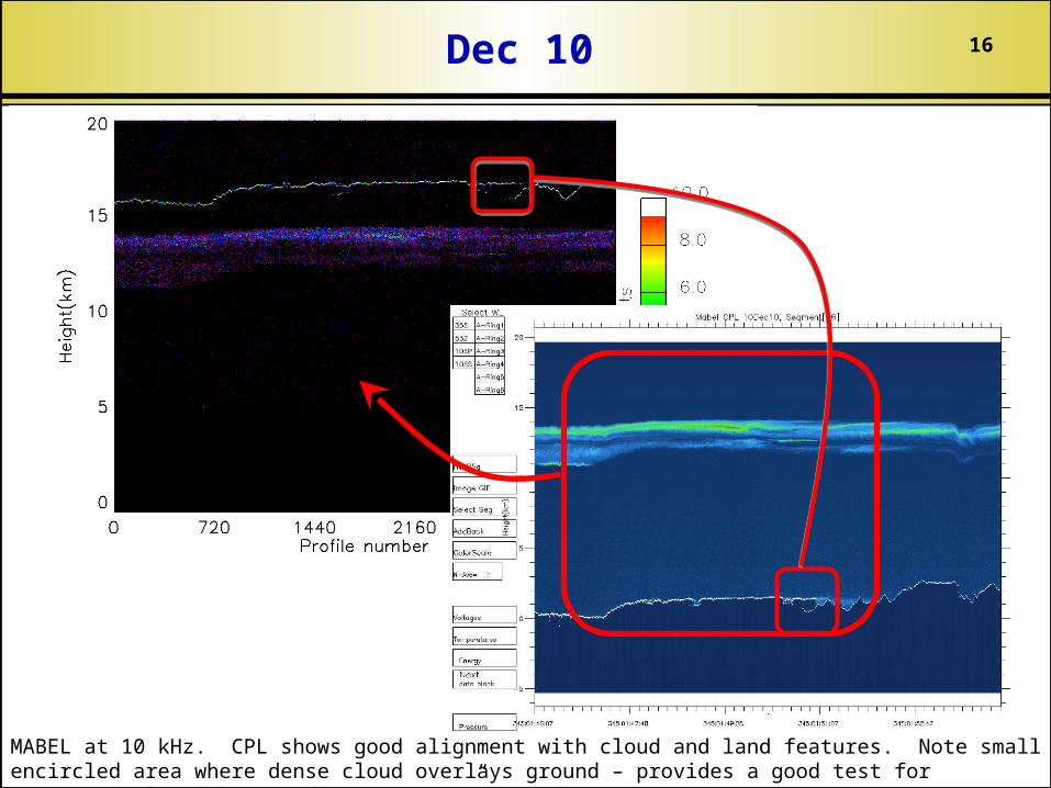
MABEL at 10 kHz. CPL shows good alignment with cloud and land features. Note small encircled area where dense cloud overlays ground – provides a good test for automated algorithms to discern “true” ground.
Dec 10
17
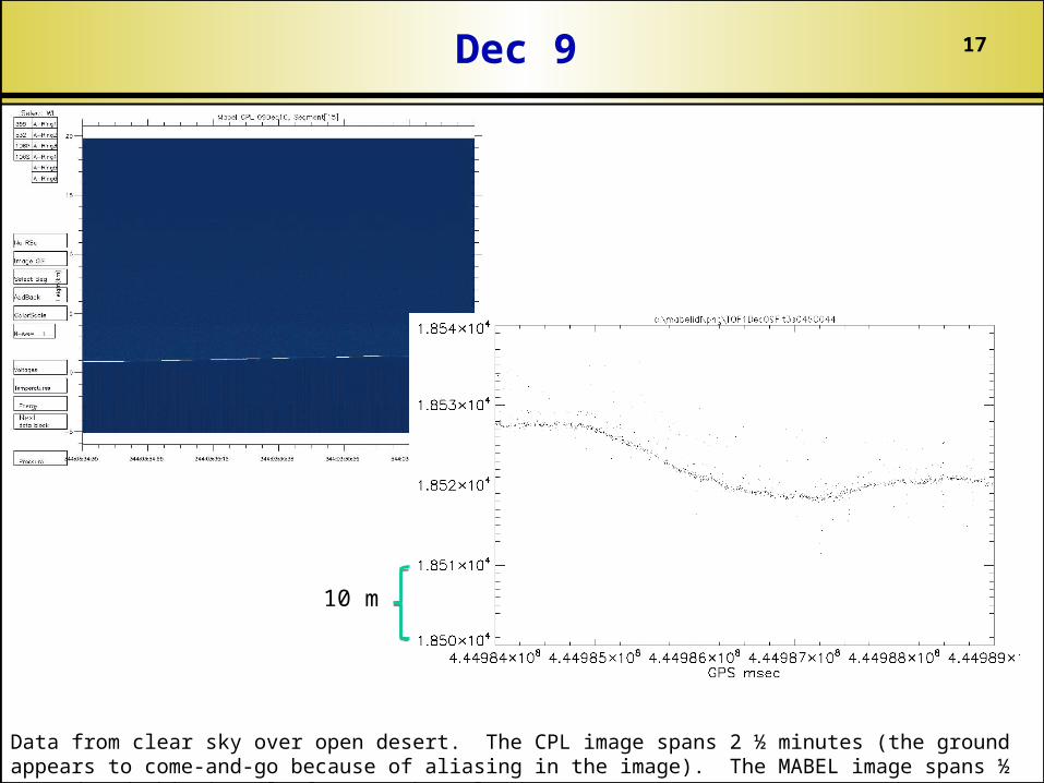
Data from clear sky over open desert. The CPL image spans 2 ½ minutes (the ground appears to come-and-go because of aliasing in the image). The MABEL image spans ½ second…and this is only for one channel.
10 m
Dec 9
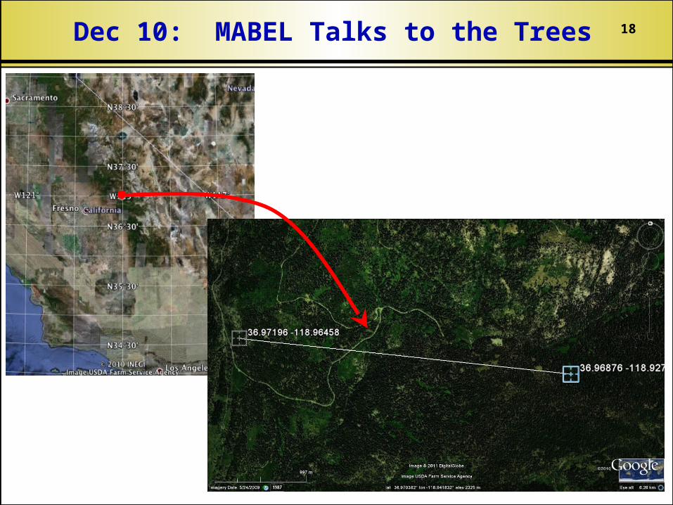
18Dec 10: MABEL Talks to the Trees
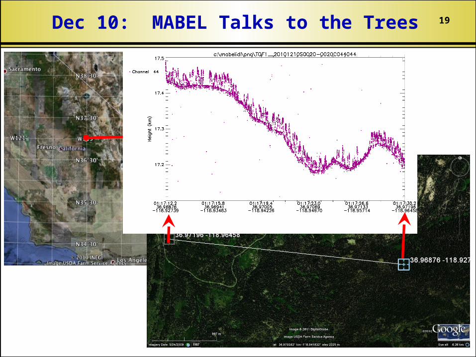
19Dec 10: MABEL Talks to the Trees
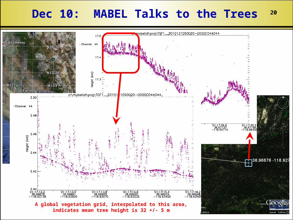
20Dec 10: MABEL Talks to the Trees
A global vegetation grid, interpolated to this area, indicates mean tree height is 32 +/- 5 m
21
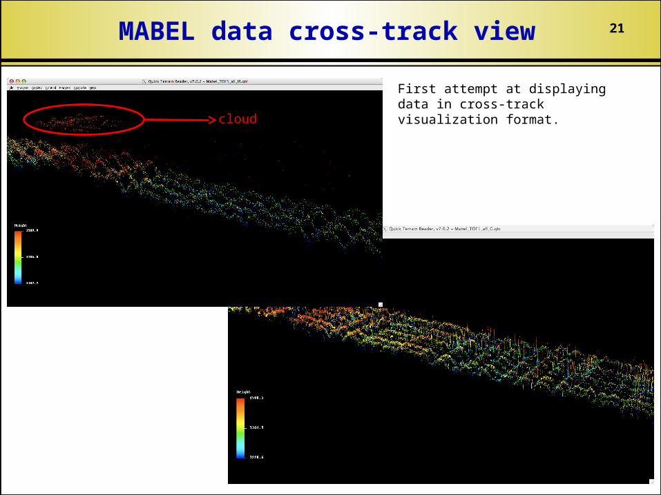
First attempt at displaying data in cross-track visualization format.
cloud
MABEL data cross-track view
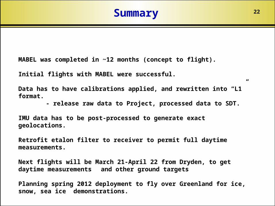
22Summary
MABEL was completed in ~12 months (concept to flight).
Initial flights with MABEL were successful.
Data has to have calibrations applied, and rewritten into “L1” format.- release raw data to Project, processed data to SDT.
IMU data has to be post-processed to generate exact geolocations.
Retrofit etalon filter to receiver to permit full daytime measurements.
Next flights will be March 21-April 22 from Dryden, to get daytime measurements and other ground targets
Planning spring 2012 deployment to fly over Greenland for ice, snow, sea ice demonstrations.
23
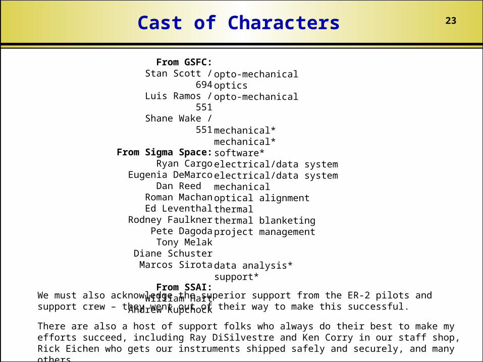
From GSFC: Stan Scott / 694
Luis Ramos / 551 Shane Wake / 551
From Sigma Space: Ryan Cargo
Eugenia DeMarco Dan Reed
Roman Machan Ed Leventhal
Rodney FaulknerPete Dagoda Tony Melak
Diane Schuster Marcos Sirota
From SSAI: William Hart
Andrew Kupchock
opto-mechanicalopticsopto-mechanical
mechanical*mechanical*software*electrical/data systemelectrical/data systemmechanicaloptical alignmentthermalthermal blanketingproject management
data analysis*support*
We must also acknowledge the superior support from the ER-2 pilots and support crew – they went out of their way to make this successful.
There are also a host of support folks who always do their best to make my efforts succeed, including Ray DiSilvestre and Ken Corry in our staff shop, Rick Eichen who gets our instruments shipped safely and securely, and many others.
Cast of Characters
24
MABEL was made possible by contributions from the following companies:
Sigma Space Corp. data system, electrical, and systems engineering
Fibertek, Inc. laser transmitter
Fiberguide, Inc. custom fiber optic assemblies
Special Optics custom telescope assemblies
Acknowledgements