Embed Size (px)
Citation preview
Engineering Structures 147 (2017) 195–206
Contents lists available at ScienceDirect
Engineering Structures
journal homepage: www.elsevier .com/ locate /engstruct
Experimental evaluation of tensile behaviour of singlecast-in-place anchor bolts in plain and steel fibre-reinforcednormal- and high-strength concrete
http://dx.doi.org/10.1016/j.engstruct.2017.05.0620141-0296/� 2017 The Authors. Published by Elsevier Ltd.This is an open access article under the CC BY license (http://creativecommons.org/licenses/by/4.0/).
⇑ Corresponding author.E-mail address: [email protected] (R. Nilforoush).
Rasoul Nilforoush ⇑, Martin Nilsson, Lennart ElfgrenLuleå University of Technology, Division of Structural and Fire Engineering, 971 87 Luleå, Sweden
a r t i c l e i n f o
Article history:Received 28 February 2017Revised 19 May 2017Accepted 31 May 2017
Keywords:Anchor boltHeaded anchorConcrete cone breakoutSplitting failureNormal-strength concreteHigh-strength concreteMember thicknessSteel fibre-reinforced concrete
a b s t r a c t
Cast-in-place anchor bolts embedded in plain and steel fibre-reinforced normal- and high-strength con-crete members were subjected to monotonic tensile loads. The influence of the concrete member thick-ness, concrete strength, and the addition of steel fibres to the concrete mixture, on the anchorage capacityand performance was evaluated. The experimental results were evaluated in terms of anchorage capacity,anchorage ductility and stiffness as well as failure mode and geometry. Furthermore, the validity ofConcrete Capacity (CC) method for predicting the tensile breakout capacity of anchor bolts in plainand steel fibre-reinforced normal- and high-strength concrete members was evaluated.The anchorage capacity and ductility increased slightly with increasing member thickness, whereas the
anchorage stiffness decreased slightly. In contrast to the anchorage ductility, the anchorage capacity andstiffness increased considerably with increasing concrete compressive strength. The anchorage capacityand ductility also increased significantly with the addition of steel fibres to the concrete mixtures. Thisenhanced capacity and ductility resulted from the improved flexural tensile strength and post-peakcracking behaviour of steel fibre-reinforced concrete.The average ratio of measured strengths to those predicted by the CC method for anchors in plain con-
crete members was increased from 1.0 to 1.17 with increasing member thickness. In steel fibre-reinforced concrete, this ratio varied from 1.29 to 1.51, depending on the member thickness and the con-crete strength.� 2017 The Authors. Published by Elsevier Ltd. This is an openaccess article under the CCBY license (http://
creativecommons.org/licenses/by/4.0/).
1. Introduction
Fastening systems, which use the mechanical interlock as a loadtransfer mechanism to convey external loads to concrete struc-tures, typically fail via concrete-related failure modes, such as con-crete cone breakout and concrete splitting. Concrete splittingfailure may occur when an anchor is placed in a relatively thin con-crete member or very close to adjacent anchor/s or concrete freeedges. Concrete cone breakout failure is characterized by the for-mation of a cone-shaped fracture surface in concrete at the anchor-ing zone. This failure mode is fairly common for various types ofanchors under tensile loads. Previous numerical and experimentalstudies on single cast-in-place anchor bolts under tension loadsshowed that the concrete cone circumferential cracking initiatesat approximately 30% of the ultimate load. In addition, the concretecone crack growth is stable up to the ultimate load [1]. It was
observed that at ultimate load, concrete cone cracks do not reachthe concrete surface. The ratio of the length of concrete cone cracksat ultimate load to the side length of a full-cone envelop variesfrom 0.5 to 0.25 with increasing anchor embedment depth [1].As the deformation at ultimate load is exceeded, the concrete conecrack growth become unstable and the full-cone envelop formscompletely with increasing deformations at post-peak load.
In general, concrete cone breakout and splitting failures arecharacterized as brittle failures because the load-displacementcurves associated with these failures decline sharply after peakload, due to rapid and unstable propagation of concrete cracks.For these brittle failure modes, the full tensile capacity of concreteis utilized, thereby resulting in concrete cracks at the anchoringzone.
Steel failure may also occur if steel in the anchor experiences atensile stress that exceeds its ultimate tensile strength while theconcrete remains undamaged. This failure is considered aductile-failure mode and is rarely observed but may occur if thesteel in the anchor is ductile and if the anchor embedment depth
196 R. Nilforoush et al. / Engineering Structures 147 (2017) 195–206
is extremely large. In addition, a ductile failure for cast-in-placeheaded anchors may also be achieved if the concrete contains rein-forcement in the anchoring zone.
Compared to the ordinary concrete (i.e. non-fibre-reinforced),Steel Fibre-Reinforced Concrete (SFRC) has shown improved flexu-ral tensile strength, residual flexural tensile strength and post-peakcracking behaviour [2]. Several studies showed that the use of SFRCmaterial leads to an improved structural capacity and performance(i.e. increased flexural, shear and punching resistance, increasedflexural stiffness, improved ductility, and reduced crack widthsand crack spacing) compared to ordinary concrete [3–5].
It is expected that fastening systems that are susceptible tobrittle-concrete failures may have an improved anchorage capacityand performance when they are placed in SFRCmembers. Althoughcurrently the use of SFRC has become popular in practice, thestructural behaviour of fastening systems in SFRC has not beenfully investigated.
Over the last few decades, several investigations, via experi-ments and numerical simulations, of various anchorage systemsin Normal-strength Plain Concrete (NPC) have led to the develop-ment of theoretical and empirical models for predicting the failureload of these systems [1,6–12]. The tested anchors were, however,all embedded in NPC members and, hence, the proposed modelsmay underestimate the anchorage capacity in SFRC members. Inaddition, concrete compressive strength for most of the testedanchors considered in the previous studies was <50 MPa, albeitin a short number of tests it was up to 70 MPa. However, the cur-rent design standards and guidelines allow designing fasteningsystems in high-strength concrete with compressive strength ofup to 70 MPa [13–17].
High-strength concrete is, by nature, more brittle than normal-strength concrete. As investigations on fastenings in this materialhave rarely been reported, further experimental evaluations of fas-tenings in concrete members with compressive strengths >50 MPaare recommended.
In addition, the influence of global bending stiffness of the con-crete member (e.g. member thickness and surface reinforcement)and size of anchor-head on the anchorage capacity and perfor-mance is neglected by the current models for predicting the tensilebearing capacity of fastenings. Nilforoush et al. [18,19] have, vianumerical simulations, recently shown that (i) the tensile breakoutcapacity of headed anchors increases with increasing the memberthickness or size of anchor-head, and/or if surface reinforcement ispresent, (ii) the anchorage is governed by the concrete splittingfailure, rather than the concrete cone breakout failure, if concretemember is relatively thin and unreinforced.
The use of high-strength SFRC may allow the design of rela-tively thin structural concrete members for loads correspondingto normal-strength concrete and, hence, its use is becoming com-mon practice. Although theoretical models were developed forthe design of such members, further investigations of anchoragebehaviour in relatively thin high-strength SFRC are required.
In this paper, the influence of the member thickness, concretestrength, and steel-fibre addition to the concrete mixture, on thetensile breakout capacity and performance of cast-in-place headedanchors is experimentally investigated. Nineteen single cast-in-place headed anchors were tested in plain and steel fibre-reinforced normal- and high-strength concrete members. Theexperimental results are presented in terms of load-displacementcurve, anchorage ultimate load, anchor displacement at the ulti-mate load and at the load corresponding to the initiation of con-crete cone circumferential cracking (i.e. considered as 30% of theultimate load), anchorage stiffness and ductility, and failure modeand geometry. In addition, the validity of the Concrete Capacity(CC) method for predicting the tensile breakout capacity of anchorbolts in plain high-strength concrete and steel fibre-reinforced
normal- and high-strength concrete is evaluated. Furthermore,another experimental study is ongoing to evaluate the influenceof member thickness, anchor head size and surface reinforcementon the tensile breakout capacity of headed anchors. The test resultswill be presented and discussed in detail in a separate paper.
2. Current models for tensile capacity of anchor bolts inconcrete
In the case of steel failure, the resistance of an anchor is directlyproportional to the steel strength and the cross-sectional area ofthe anchor shaft. Although the failure load associated with this fail-ure is quite simple and well understood, the established theoreticalmodel for determining the failure load associated with concretesplitting failure is more complex. In fact, the failure load for split-ting failure of a particular anchor type is often determined byapproval tests.
The failure load associated with concrete cone breakout can bereasonably calculated via the Concrete Capacity (CC) method(referred to as the Concrete Capacity Design (CCD) method in theUS), proposed by Fuchs et al. [12]. The CC method, which is a basicmodel for predicting the tensile breakout capacity of fastening sys-tems in concrete, has been incorporated into (i) several designstandards in the US (e.g. ACI 349-01 [13] and ACI 318-08 [14]),(ii) various design-oriented documents in Europe (e.g. CEB DesignGuide [15] and CEN/TS 1992-4 [16]), and (iii) internationally inthe fib Bulletin 58 [17]. Based on the CC method, the mean tensilebreakout capacity of a single cast-in-place anchor, unaffected byconcrete free-edge influences or overlapping cones of adjacentanchors, can be evaluated from:
Nu;m ¼ kffiffiffiffiffiffif cc
qh1:5ef ð1Þ
where Nu,m: mean concrete cone breakout capacity of a singleanchor [N], fcc: concrete cube compressive strength [MPa], hef:anchor effective embedment depth [mm], and k: empirical factor[N0.5/mm0.5] of 15.5, obtained from several tests on cast-in-placeundercut and headed anchors in uncracked concrete members.The CC method assumes a concrete cone angle of �35�, with respectto the concrete surface, which leads to an idealized projected conearea of �3.0hef � 3.0hef on the concrete surface [12].
3. Experimental program
The experimental study was performed in the laboratory of theDivision of Structural and Fire Engineering at Luleå University ofTechnology (LTU), Sweden. A total of nineteen single cast-in-place anchor bolts were subjected to monotonic tensile loading.Testing parameters, such as the concrete member thickness, con-crete compressive strength, and the addition of steel fibres to theconcrete base material, were considered. Four different test serieswere considered in this experimental program (see Table 1 formatrix of experimental program). The typical geometry of the testspecimens, including both the side and top views, is shown inFig. 1. The test specimens were designed to fail via brittle-failuremodes associated with concrete (the designed tensile strength ofthe steel anchor bolts was sufficiently high to prevent steel failure).In all test series, a single anchor bolt with an effective embedmentdepth of hef = 220 mm was placed in the center of a concrete slab.The length (L) and width (W) of concrete slabs for all specimenswere identical (L =W = 1300 mm), whereas the height of concreteslabs (H) varied from 1.5 to 3.0 times the anchor embedment depth(i.e. H = 330, 440 and 660 mm).
In series (i)–(iv), the anchor bolts were tested in Normal-strength Plain Concrete (NPC) members, Normal-strength steelFibre-Reinforced Concrete (NFRC) members, High-strength Plain
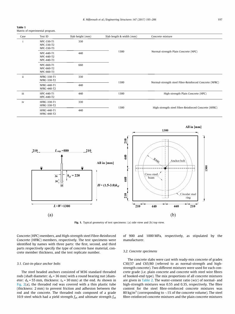
Table 1Matrix of experimental program.
Case Test ID Slab height (mm) Slab length & width (mm) Concrete mixture
i NPC-330-T1 330
1300 Normal-strength Plain Concrete (NPC)
NPC-330-T2NPC-330-T3
NPC-440-T1 440NPC-440-T2NPC-440-T3
NPC-660-T1 660NPC-660-T2NPC-660-T3
ii NFRC-330-T1 330
1300 Normal-strength steel Fibre-Reinforced Concrete (NFRC)NFRC-330-T2
NFRC-440-T1 440NFRC-440-T2
iii HPC-440-T1 440 1300 High-strength Plain Concrete (HPC)HPC-440-T2
iv HFRC-330-T1 330
1300 High-strength steel Fibre-Reinforced Concrete (HFRC)HFRC-330-T2
HFRC-440-T1 440HFRC-440-T2
Fig. 1. Typical geometry of test specimens: (a) side view and (b) top view.
R. Nilforoush et al. / Engineering Structures 147 (2017) 195–206 197
Concrete (HPC) members, and High-strength steel Fibre-ReinforcedConcrete (HFRC) members, respectively. The test specimens wereidentified by names with three parts: the first, second, and thirdparts respectively specify the type of concrete base material, con-crete member thickness, and the test replicate number.
3.1. Cast-in-place anchor bolts
The steel headed anchors consisted of M36 standard threadedrods (shaft diameter: d0 = 36 mm) with a round bearing nut (diam-eter: dh = 55 mm, thickness: th = 30 mm) at the end. As shown inFig. 2(a), the threaded rod was covered with a thin plastic tube(thickness: 2 mm) to prevent friction and adhesion between therod and the concrete. The threaded rods composed of a grade10.9 steel which had a yield strength fyk and ultimate strength fuk
of 900 and 1000 MPa, respectively, as stipulated by themanufacturer.
3.2. Concrete specimens
The concrete slabs were cast with ready-mix concrete of gradesC30/37 and C65/80 (referred to as normal-strength and high-strength concrete). Two different mixtures were used for each con-crete grade (i.e. plain concrete and concrete with steel wire fibresof hooked-end type). The mix proportions of all concrete mixturesare given in Table 2. The water-cement ratio (w/c) of normal- andhigh-strength mixtures was 0.55 and 0.35, respectively. The fibrecontent for the steel fibre-reinforced concrete mixtures was80 kg/m3 (corresponding to �1% of the concrete volume). The steelfibre-reinforced concrete mixtures and the plain concrete mixtures
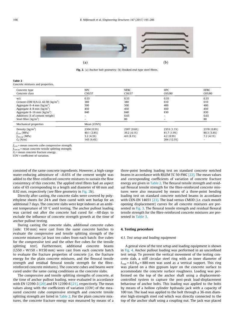
Fig. 2. (a) Anchor bolt geometry; (b) Hooked-end type steel fibres.
Table 2Concrete mixtures and properties.
Concrete type NPC NFRC HPC HFRCConcrete class C30/37 C30/37 C65/80 C65/80
w/c 0.55 0.55 0.35 0.35Cement-CEM II/A-LL 42.5R (kg/m3) 380 380 610 610Aggregate 0–4 mm (kg/m3) 500 500 400 400Aggregate 4–8 mm (kg/m3) 450 450 450 450Aggregate 8–16 mm (kg/m3) 840 840 830 830Additives (% of cement weight) – 0.65 – 0.65Steel fibre (kg/m3) – 80 – 80
Mechanical properties Mean (COV%)
Density (kg/m3) 2304 (0.5%) 2307 (0.6%) 2353 (1.1%) 2378 (0.8%)fccm (MPa) 40.1 (2.8%) 39.2 (4.1%) 81.7 (1.9%) 80.3 (3.4%)fctm,sp (MPa) 3.2 (4.3%) 4.0 (8.1%) 4.2 (8.9%) 7.2 (4.1%)Gf (N/m) 145 (6.4%) – 204 (12.5%) –
fccm = mean concrete cube compressive strength.fctm,sp = mean concrete tensile splitting strength.Gf = mean concrete fracture energy.COV = coefficient of variation.
198 R. Nilforoush et al. / Engineering Structures 147 (2017) 195–206
consisted of the same concrete ingredients. However, a high-rangewater-reducing admixture of �0.65% of the cement weight wasadded to the fibre-reinforced concrete mixtures to sustain the flowconsistency of this concrete. The applied steel fibres had an aspectratio of 65 corresponding to a length and diameter of 60 mm and0.92 mm, respectively (see fibre geometry in Fig. 2b).
Directly after casting, the concrete slabs were covered by poly-ethylene sheets for 24 h and then cured with wet burlap for anadditional 7 days. The concrete slabs were kept indoors at an ambi-ent temperature of 10 �C until testing. The anchor pullout loadingwas carried out after the concrete had cured for �60 days toexclude the influence of concrete strength growth at the time ofanchor pullout testing.
During casting the concrete slabs, additional concrete cubes(side: 150 mm) were cast from the same concrete batches toevaluate the compressive and tensile splitting strength of theconcrete mixtures (at least ten cubes from each batch: five cubesfor the compressive test and the other five cubes for the tensilesplitting test). Furthermore, additional concrete beams(L550 �W150 � H150 mm) were cast from each concrete batchto evaluate the fracture properties of concrete (i.e. the fractureenergy for the plain concrete mixtures, and the flexural tensilestrength and residual flexural tensile strength for the fibre-reinforced concrete mixtures). The concrete cubes and beams werecured under the same curing conditions as the concrete slabs.
The compressive and tensile splitting strengths of concrete, atthe time of anchor pullout loading, were evaluated in accordancewith EN 12390-3 [20] and EN 12390-6 [21], respectively. The meanvalues along with the coefficients of variation (COV) of the mea-sured concrete cube compressive strength and concrete tensilesplitting strength are listed in Table 2. For the plain concrete mix-tures, the concrete fracture energy was measured by means of a
three-point bending loading test on standard concrete notchedbeams in accordance with RILEM TC 50-FMC [22]. The mean valuesand corresponding coefficients of variation of concrete fractureenergy are given in Table 2. The flexural tensile strength and resid-ual flexural tensile strength for the fibre-reinforced concrete mix-tures were also measured by means of a three-point bendingloading test on standard concrete notched beams in accordancewith CEN-EN 14651 [23]. The load versus CMOD (i.e. crack mouthopening displacement) curves for all concrete mixtures are pre-sented in Fig. 3. The flexural tensile strength and residual flexuraltensile strength for the fibre-reinforced concrete mixtures are pre-sented in Table 3.
4. Testing procedure
4.1. Test setup and loading equipment
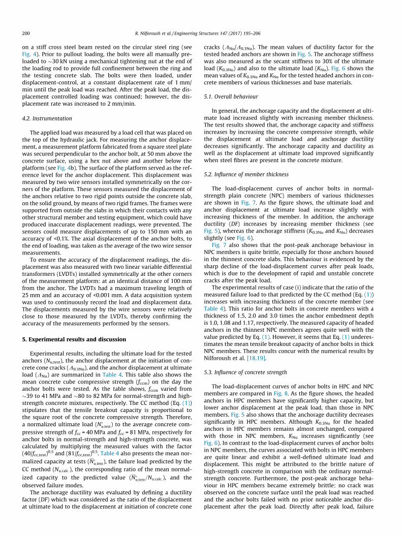
A genral view of the test setup and loading equipment is shownin Fig. 4. Anchor pullout loading was performed in an unconfinedtest setup. To prevent the vertical movement of the testing con-crete slab, a stiff circular steel ring with an inner diameter ofLsup = 4.0�hef = 880 mm was used as a vertical support. This ringwas placed on a thin gypsum layer on the concrete surface toaccommodate the concrete surface roughness. Loading was per-formed on the top of the anchor shaft using a displacement-controlled system to capture the post-peak load-displacementbehaviour of anchor bolts. This loading was applied to the boltsby means of a hollow cylinder hydraulic jack with a capacity of100 ton. The load was applied to the bolt through a 36-mm diam-eter high-strength steel rod which was directly connected to thetop of the anchor shaft using a coupling nut. The jack was placed
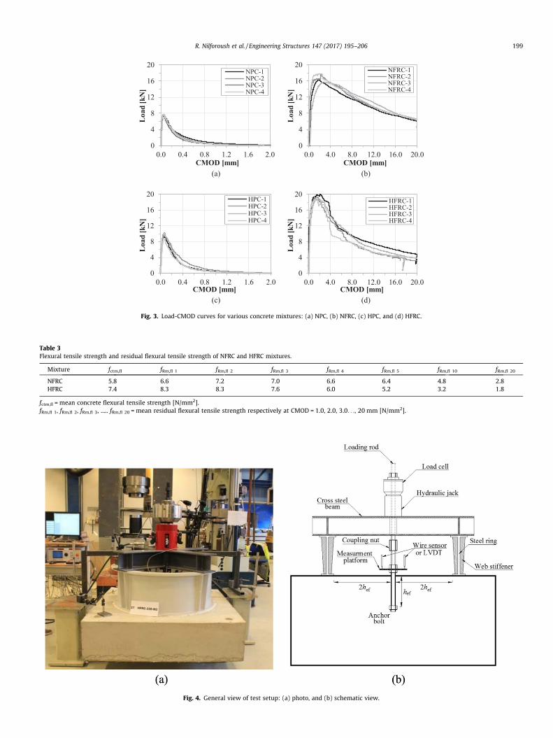
Fig. 3. Load-CMOD curves for various concrete mixtures: (a) NPC, (b) NFRC, (c) HPC, and (d) HFRC.
Table 3Flexural tensile strength and residual flexural tensile strength of NFRC and HFRC mixtures.
Mixture fctm,fl fRm,fl 1 fRm,fl 2 fRm,fl 3 fRm,fl 4 fRm,fl 5 fRm,fl 10 fRm,fl 20
NFRC 5.8 6.6 7.2 7.0 6.6 6.4 4.8 2.8HFRC 7.4 8.3 8.3 7.6 6.0 5.2 3.2 1.8
fctm,fl = mean concrete flexural tensile strength [N/mm2].fRm,fl 1, fRm,fl 2, fRm,fl 3, ..... fRm,fl 20 = mean residual flexural tensile strength respectively at CMOD = 1.0, 2.0, 3.0. . ., 20 mm [N/mm2].
Fig. 4. General view of test setup: (a) photo, and (b) schematic view.
R. Nilforoush et al. / Engineering Structures 147 (2017) 195–206 199
200 R. Nilforoush et al. / Engineering Structures 147 (2017) 195–206
on a stiff cross steel beam rested on the circular steel ring (seeFig. 4). Prior to pullout loading, the bolts were all manually pre-loaded to �30 kN using a mechanical tightening nut at the end ofthe loading rod to provide full confinement between the ring andthe testing concrete slab. The bolts were then loaded, underdisplacement-control, at a constant displacement rate of 1 mm/min until the peak load was reached. After the peak load, the dis-placement controlled loading was continued; however, the dis-placement rate was increased to 2 mm/min.
4.2. Instrumentation
The applied load was measured by a load cell that was placed onthe top of the hydraulic jack. For measuring the anchor displace-ment, a measurement platform fabricated from a square steel platewas secured perpendicular to the anchor bolt, at 50 mm above theconcrete surface, using a hex nut above and another below theplatform (see Fig. 4b). The surface of the platform served as the ref-erence level for the anchor displacement. This displacement wasmeasured by two wire sensors installed symmetrically on the cor-ners of the platform. These sensors measured the displacement ofthe anchors relative to two rigid points outside the concrete slab,on the solid ground, by means of two rigid frames. The frames weresupported from outside the slabs in which their contacts with anyother structural member and testing equipment, which could haveproduced inaccurate displacement readings, were prevented. Thesensors could measure displacements of up to 150 mm with anaccuracy of <0.1%. The axial displacement of the anchor bolts, tothe end of loading, was taken as the average of the two wire sensormeasurements.
To ensure the accuracy of the displacement readings, the dis-placement was also measured with two linear variable differentialtransformers (LVDTs) installed symmetrically at the other cornersof the measurement platform: at an identical distance of 100 mmfrom the anchor. The LVDTs had a maximum traveling length of25 mm and an accuracy of <0.001 mm. A data acquisition systemwas used to continuously record the load and displacement data.The displacements measured by the wire sensors were relativelyclose to those measured by the LVDTs, thereby confirming theaccuracy of the measurements performed by the sensors.
5. Experimental results and discussion
Experimental results, including the ultimate load for the testedanchors (Nu,test), the anchor displacement at the initiation of con-crete cone cracks (D0.3Nu), and the anchor displacement at ultimateload (DNu) are summarized in Table 4. This table also shows themean concrete cube compressive strength (fccm) on the day theanchor bolts were tested. As the table shows, fccm varied from�39 to 41 MPa and �80 to 82 MPa for normal-strength and high-strength concrete mixtures, respectively. The CC method (Eq. (1))stipulates that the tensile breakout capacity is proportional tothe square root of the concrete compressive strength. Therefore,a normalized ultimate load (N�
u;test) to the average concrete com-pressive strength of fcc = 40 MPa and fcc = 81 MPa, respectively foranchor bolts in normal-strength and high-strength concrete, wascalculated by multiplying the measured values with the factor(40/fcc,test)0.5 and (81/fcc,test)0.5. Table 4 also presents the mean nor-malized capacity at tests (N�
u;test), the failure load predicted by theCC method (Nu;calc:), the corresponding ratio of the mean normal-ized capacity to the predicted value (N�
u;test=Nu;calc:), and theobserved failure modes.
The anchorage ductility was evaluated by defining a ductilityfactor (DF) which was considered as the ratio of the displacementat ultimate load to the displacement at initiation of concrete cone
cracks (DNu/D0.3Nu). The mean values of ductility factor for thetested headed anchors are shown in Fig. 5. The anchorage stiffnesswas also measured as the secant stiffness to 30% of the ultimateload (K0.3Nu) and also to the ultimate load (KNu). Fig. 6 shows themean values of K0.3Nu and KNu for the tested headed anchors in con-crete members of various thicknesses and base materials.
5.1. Overall behaviour
In general, the anchorage capacity and the displacement at ulti-mate load increased slightly with increasing member thickness.The test results showed that, the anchorage capacity and stiffnessincreases by increasing the concrete compressive strength, whilethe displacement at ultimate load and anchorage ductilitydecreases significantly. The anchorage capacity and ductility aswell as the displacement at ultimate load improved significantlywhen steel fibres are present in the concrete mixture.
5.2. Influence of member thickness
The load-displacement curves of anchor bolts in normal-strength plain concrete (NPC) members of various thicknessesare shown in Fig. 7. As the figure shows, the ultimate load andanchor displacement at ultimate load increase slightly withincreasing thickness of the member. In addition, the anchorageductility (DF) increases by increasing member thickness (seeFig. 5), whereas the anchorage stiffness (K0.3Nu and KNu) decreasesslightly (see Fig. 6).
Fig. 7 also shows that the post-peak anchorage behaviour inNPC members is quite brittle, especially for those anchors housedin the thinnest concrete slabs. This behaviour is evidenced by thesharp decline of the load-displacement curves after peak loads,which is due to the development of rapid and unstable concretecracks after the peak load.
The experimental results of case (i) indicate that the ratio of themeasured failure load to that predicted by the CC method (Eq. (1))increases with increasing thickness of the concrete member (seeTable 4). This ratio for anchor bolts in concrete members with athickness of 1.5, 2.0 and 3.0 times the anchor embedment depthis 1.0, 1.08 and 1.17, respectively. The measured capacity of headedanchors in the thinnest NPC members agrees quite well with thevalue predicted by Eq. (1). However, it seems that Eq. (1) underes-timates the mean tensile breakout capacity of anchor bolts in thickNPC members. These results concur with the numerical results byNilforoush et al. [18,19].
5.3. Influence of concrete strength
The load-displacement curves of anchor bolts in HPC and NPCmembers are compared in Fig. 8. As the figure shows, the headedanchors in HPC members have significantly higher capacity, butlower anchor displacement at the peak load, than those in NPCmembers. Fig. 5 also shows that the anchorage ductility decreasessignificantly in HPC members. Although K0.3Nu for the headedanchors in HPC members remains almost unchanged, comparedwith those in NPC members, KNu increases significantly (seeFig. 6). In contrast to the load-displacement curves of anchor boltsin NPC members, the curves associated with bolts in HPC membersare quite linear and exhibit a well-defined ultimate load anddisplacement. This might be attributed to the brittle nature ofhigh-strength concrete in comparison with the ordinary normal-strength concrete. Furthermore, the post-peak anchorage beha-viour in HPC members became extremely brittle: no crack wasobserved on the concrete surface until the peak load was reachedand the anchor bolts failed with no prior noticeable anchor dis-placement after the peak load. Directly after peak load, failure
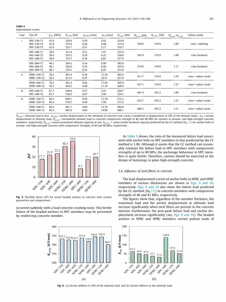
Table 4Experimental results.
Case Test ID fccm [MPa] Nu;test [kN] D0.3Nu [mm] DNu [mm] N�u;test [kN] N�
u;test [kN] Nu;calc: [kN] N�u;test=Nu;calc: Failure mode
i NPC-330-T1 41.0 329.0 0.29 5.92 324.8320.0 319.9 1.00 cone + splittingNPC-330-T2 41.0 319.4 0.28 4.48 315.4
NPC-330-T3 41.0 323.7 0.31 5.17 319.7
NPC-440-T1 38.9 331.4 0.31 7.47 335.9343.9 319.9 1.08 cone breakoutNPC-440-T2 38.9 353.2 0.29 6.25 358.0
NPC-440-T3 38.9 333.3 0.34 6.82 337.9
NPC-660-T1 40.1 384.3 0.34 6.90 383.6374.9 319.9 1.17 cone breakoutNPC-660-T2 40.1 366.0 0.35 8.96 365.4
NPC-660-T3 40.1 376.5 0.35 8.45 375.8
ii NFRC-330-T1 39.2 401.9 0.38 11.54 405.9411.7 319.9 1.29 cone + radial cracks
NFRC-330-T2 39.2 413.5 0.35 10.51 417.6
NFRC-440-T1 39.2 441.5 0.42 17.99 445.9437.1 319.9 1.37 cone + radial cracks
NFRC-440-T2 39.2 424.2 0.40 11.10 428.4
iii HPC-440-T1 81.7 430.6 0.37 3.47 428.7481.4 455.2 1.06 cone breakout
HPC-440-T2 81.7 536.5 0.47 3.44 534.1
iv HFRC-330-T1 80.3 669.1 0.59 11.39 672.2622.7 455.2 1.37 cone + radial cracks
HFRC-330-T2 80.3 570.5 0.49 7.58 573.2
HFRC-440-T1 80.3 681.7 0.68 12.78 684.9686.5 455.2 1.51 cone + radial cracks
HFRC-440-T2 80.3 685.0 0.69 14.09 688.1
Nu;test = ultimate load at test; D0.3Nu = anchor displacement at the initiation of concrete cone cracks (considered as displacement at 30% of the ultimate load); DNu = anchordisplacement at ultimate load; N�
u;test = normalized ultimate load to concrete compressive strength of 40 and 80 MPa for anchors in normal- and high-strength concretemembers, respectively; N�
u;test = mean normalized ultimate capacity at test; Nu;calc: = mean tensile breakout capacity predicted by the CC method (Eq. (1)) for anchor bolts innormal- and high-strength concrete with compressive strengths of 40 and 80 MPa, respectively.
Fig. 5. Ductility factor (DF) for tested headed anchors in concrete with variousgeometries and compositions.
R. Nilforoush et al. / Engineering Structures 147 (2017) 195–206 201
occurred suddenly with a loud concrete crushing noise. This brittlefailure of the headed anchors in HPC members may be preventedby reinforcing concrete member.
Fig. 6. (a) Secant stiffness to 30% of the ultimate loa
As Table 3 shows, the ratio of the measured failure load associ-ated with anchor bolts in HPC members to that predicted by the CCmethod is 1.06. Although it seems that the CC method can reason-ably estimate the failure load in HPC members with compressivestrengths of up to 80 MPa, the anchorage behaviour in HPC mem-bers is quite brittle. Therefore, caution should be exercised in thedesign of fastenings in plain high-strength concrete.
5.4. Influence of steel fibres in concrete
The load-displacement curves of anchor bolts in NFRC and HFRCmembers of various thicknesses are shown in Figs. 9 and 10,respectively. Figs. 9 and 10 also show the failure load predictedby the CC method (Eq. (1)) in concrete members with compressivestrengths of 40 and 81 MPa, respectively.
The figures show that, regardless of the member thickness, themaximum load and the anchor displacement at ultimate loadincrease significantly when steel fibres are present in the concretemixture. Furthermore, the post-peak failure load and anchor dis-placement increase significantly (see, Figs. 9 and 10). The headedanchors in NFRC and HFRC members carried pullout loads of
d, and (b) Secant stiffness to the ultimate load.

Fig. 7. Load-displacement curves of anchor bolts in NPC members of various thicknesses: (a) H = 1.5�hef, (b) H = 2.0�hef, and (c) H = 3.0�hef.
Fig. 8. Comparison of load-displacement curves of anchor bolts in NPC and HPCmembers.
202 R. Nilforoush et al. / Engineering Structures 147 (2017) 195–206
>300 kN at anchor displacements of up to 40 mm. The addition ofsteel fibres also resulted in a significant increase in the anchorageductility (see Fig. 5). As anchor displacement at peak load was con-sidered for evaluating the ductility factor and anchor bolts in SFRCmembers showed quite larger displacements after peak load (com-pared to the anchors in plain concrete members), thus the actualductility factor of anchors in SFRC may be quite larger than the val-ues presented in Fig. 5.
Fig. 9. Comparison of load-displacement curves of anchor bolts in NPC and
As Table 4 shows, when H is increased from 1.5hef to 2.0hef, theratio of the failure load to the load predicted by the CC method var-ies from (i) 1.29 to 1.37 and (ii) 1.37 to 1.51 for anchor bolts inNFRC and HFRC members, respectively. This indicates that theanchorage capacity in SFRC members also increases with increas-ing member thickness. The ratio of the failure load to the load pre-dicted by the CC method further indicates that the CC methodconsiderably underestimates the tensile breakout capacity ofanchor bolts in SFRC. As the compressive strength of NPC andHPC mixtures are approximately identical to NFRC and HFRC mix-tures, respectively, it seems that the concrete cone failure load ofanchor bolts in the steel fibre-reinforced concrete is influencedby the fracture properties of concrete (i.e. tensile strength and frac-ture energy), rather than the compressive strength.
5.5. Failure mode and failure geometry
Fig. 11 shows the crack patterns at failure for anchor bolts inNPC members of various thicknesses. The NPC members allundergo concrete cone breakout, except for the thinnest NPCmem-bers which failed via mixed-mode concrete cone and splitting fail-ure. In fact, by increasing the load on anchor bolts in the thinnestNPC members, the concrete cone circumferential cracks are initi-ated at the anchor head and then propagated towards the concretesurface. However, concrete bending/splitting cracking also occursand dominates the failure mode, eventually dividing the concreteslab into two separate pieces at the anchor peak load. This mixedmode failure mechanism explains the more brittle post-peak
NFRC members of various thicknesses: (a) H = 1.5�hef and (b) H = 2.0�hef.
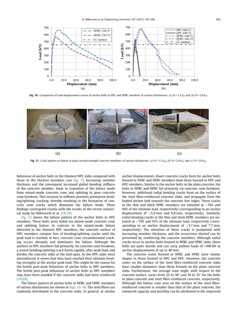
Fig. 10. Comparison of load-displacement curves of anchor bolts in HPC and HFRC members of various thicknesses: (a) H = 1.5�hef and (b) H = 2.0�hef.
Fig. 11. Crack pattern at failure in plain normal-strength concrete members of various thicknesses: (a) H = 1.5�hef, (b) H = 2.0�hef, and (c) H = 3.0�hef.
R. Nilforoush et al. / Engineering Structures 147 (2017) 195–206 203
behaviour of anchor bolts in the thinnest NPC slabs compared withthose in the thickest members (see Fig. 7). Increasing memberthickness and the consequent increased global bending stiffnessof the concrete member, leads to transition of the failure modefrom mixed-mode concrete cone and splitting to pure concretecone breakout. This increase in stiffness prevents premature bend-ing/splitting cracking, thereby resulting in the formation of con-crete cone cracks which dominate the failure mode. Thesefindings correspond closely with the results of the recent numeri-cal study by Nilforoush et al. [18,19].
Fig. 12 shows the failure pattern of the anchor bolts in HPCmembers. These bolts were failed via mixed-mode concrete coneand splitting failure. In contrast to the mixed-mode failureobserved in the thinnest NPC members, the concrete surface ofHPC members remains free of bending/splitting cracks until thepeak load is reached. In fact, concrete cone circumferential crack-ing occurs abruptly and dominates the failure. Although theanchors in HPC members fail primarily via concrete cone breakout,a severe bending/splitting crack forms rapidly, after peak load, anddivides the concrete slabs at the mid-span. As the HPC slabs wereunreinforced, it seems that they have reached their ultimate bend-ing strengths at the anchor peak load. This might be the reason forthe brittle post-peak behaviour of anchor bolts in HPC members.The brittle post-peak behaviour of anchor bolts in HPC membersmay have been avoided if the concrete slabs had been reinforced[19,24].
The failure pattern of anchor bolts in NFRC and HFRC membersof various thicknesses are shown in Figs. 13–16. The steel fibres arerandomly distributed in the concrete slabs. In general, at similar
anchor displacements, fewer concrete cracks form for anchor boltshoused in NFRC and HFRC members than those housed in NPC andHPC members. Similar to the anchor bolts in the plain concrete, thebolts in NFRC and HFRC fail primarily via concrete cone breakout.However, additional radial bending cracks form on the surface ofthe steel fibre-reinforced concrete slabs, and propagate from theloaded anchor bolt towards the concrete free edges. These cracksin the thin and thick NFRC members are initiated at �76% and94% of the ultimate load, respectively (corresponding to an anchordisplacement of �5.9 mm and 9.8 mm, respectively). Similarly,radial bending cracks in the thin and thick HFRC members are ini-tiated at �79% and 92% of the ultimate load, respectively (corre-sponding to an anchor displacement of �3.7 mm and 7.7 mm,respectively). The initiation of these cracks is postponed withincreasing member thickness, and the occurrence thereof can beprevented by reinforcing the concrete members. Although radialcracks occur in anchor bolts housed in NFRC and HFRC slabs, thesebolts are quite ductile and can carry pullout loads of >300 kN atanchor displacements of up to 40 mm.
The concrete cones formed in NFRC and HFRC have similarshapes to those formed in NPC and HPC. However, the concretecones on the surface of the steel fibre-reinforced concrete slabshave smaller diameters than those formed on the plain concreteslabs. Furthermore, the average cone angle, with respect to theconcrete surface, varies from 25 to 30� and 30 to 35� for the boltsin plain concrete and steel fibre-reinforced concrete, respectively.Although the failure cone area on the surface of the steel fibre-reinforced concrete is smaller than that of the plain concrete, theenhanced capacity and ductility can be attributed to the improved
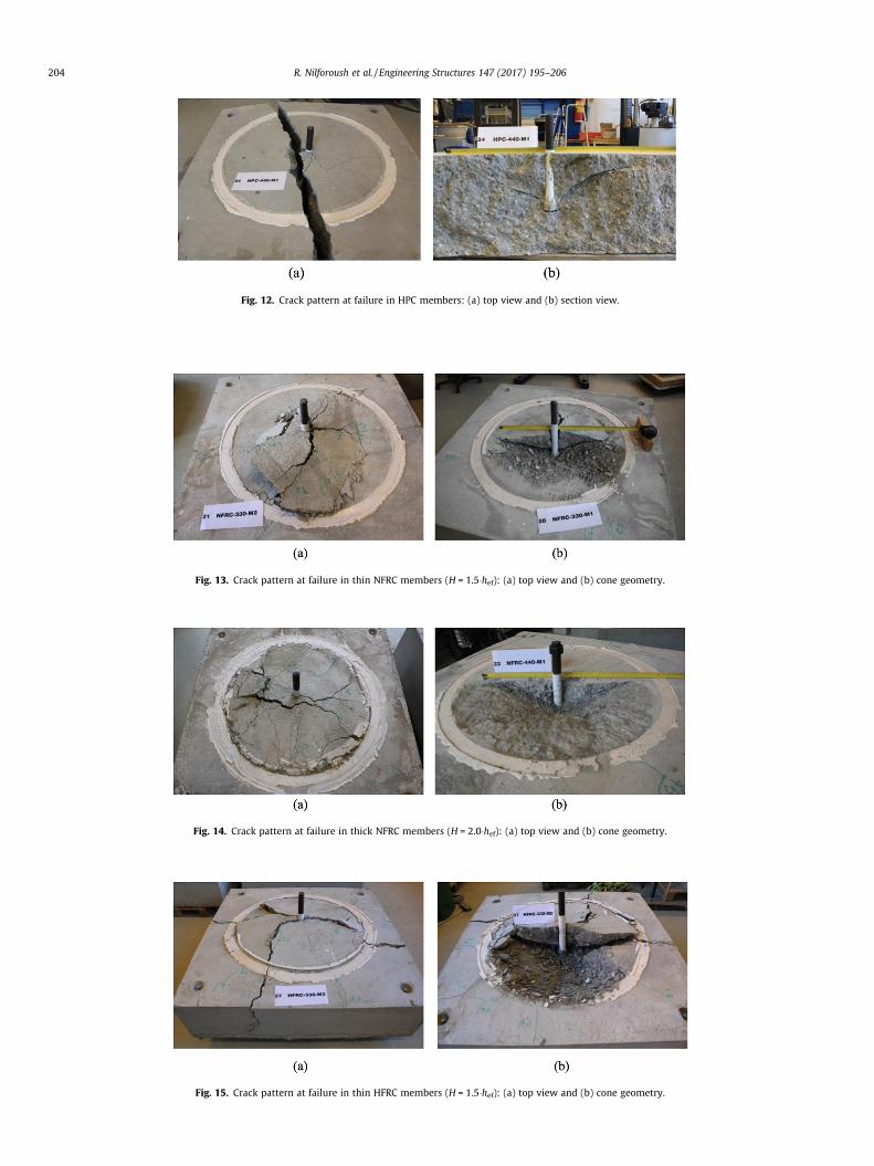
Fig. 12. Crack pattern at failure in HPC members: (a) top view and (b) section view.
Fig. 13. Crack pattern at failure in thin NFRC members (H = 1.5�hef): (a) top view and (b) cone geometry.
Fig. 14. Crack pattern at failure in thick NFRC members (H = 2.0�hef): (a) top view and (b) cone geometry.
Fig. 15. Crack pattern at failure in thin HFRC members (H = 1.5�hef): (a) top view and (b) cone geometry.
204 R. Nilforoush et al. / Engineering Structures 147 (2017) 195–206

Fig. 16. Crack pattern at failure in thick HFRC members (H = 2.0�hef): (a) top view and (b) cone geometry.
R. Nilforoush et al. / Engineering Structures 147 (2017) 195–206 205
flexural tensile strength, residual flexural tensile strength andpost-peak cracking behaviour of steel fibre-reinforced concrete(see Fig. 3).
6. Conclusions
The tensile breakout capacity and performance of cast-in-placeheaded anchors embedded in plain and steel fibre-reinforcednormal- and high-strength concrete members of various thick-nesses were experimentally evaluated. Testing parameters suchas the member thickness, concrete compressive strength, and theaddition of steel fibres to the concrete base material were consid-ered. Based on the experimental results, the following conclusionscan be drawn:
1. The tensile breakout capacity of headed anchors increases withincreasing the thickness of concrete member. The maximumload observed during testing of the thinnest plain concretemembers corresponds closely with that predicted by the Con-crete Capacity (CC) method (Eq. (1)). However, the anchoragecapacity increases up to 17% with increasing the member thick-ness from 1.5 to 3.0 times the anchor embedment depth.
2. The tensile bearing capacity of anchor bolts increases byincreasing concrete strength. However, the anchorage beha-viour in the High-strength Plain Concrete (HPC) members wasmore brittle than that in the Normal-strength Plain Concrete(NPC) members. These bolts failed suddenly without priornoticeable anchor displacement after peak load. The CC method(Eq. (1)) provides reasonable estimation of the failure load ofanchor bolts in high-strength concrete members with compres-sive strengths of up to 80 MPa. However, caution should beexercised in designing anchor bolts in HPC members. It is highlyrecommended to confine concrete member by some orthogonalsurface reinforcement to overcome the brittle post-peak beha-viour of anchors in HPC. Alternatively, the addition of 80 kg/m3 steel fibres of hooked-end type to concrete can preventthe brittle post-peak behaviour of headed anchors in bothNPC and HPC members.
3. The addition of steel fibres to the concrete mixture leads to asignificant increase in the tensile breakout capacity of headedanchors in both normal- and high-strength concretes. Theanchor displacement at ultimate load and the anchorage resid-ual strength and ductility also increase significantly. The exper-imental results showed that the CC method (Eq. (1))considerably underestimates the tensile breakout capacity ofheaded anchors in steel-fibre reinforced concrete.
4. The tested headed anchors all failed via concrete cone breakout,except for those in the thinnest NPC members which failed viaconcrete splitting. The splitting-failure mode of the thin plainconcretes transitioned to concrete cone breakout when themember thickness was increased.
5. At the same anchor displacement, fewer concrete cracks formedin anchor bolts in Normal-strength Fibre-Reinforced (NFRC) andHigh-strength Fibre-Reinforced Concrete (HFRC) members thanin NPC and HPC members.
6. To propose a reliable model for predicting failure load ofanchors in SFRC material, further experimental and numericalevaluations of anchors at various embedment depths in SFRCmembers of various geometries and properties are required.
Acknowledgments
This work was funded by Energiforsk, a Swedish EnergyResearch Centre, and by SBUF, the Development Fund of the Swed-ish Construction Industry. The assistance of Mats Petersson fromthe laboratory of the Division of Structural and Fire Engineeringat Luleå University of Technology (LTU) is gratefully appreciated.
References
[1] Eligehausen R, Mallée R, Silva JF. Anchorage in concrete construction. Berlin,Germany: Ernst & Sohn; 2006. p. 378.
[2] Balaguru N, Shah SP. Fiber-reinforced cement composites. New York: McGraw-Hill; 1992. p. 530.
[3] Löfgren I. Fibre-reinforced concrete for industrial construction – a fracturemechanics approach to material testing and structural analysis Doctoralthesis. Chalmers University of Technology; 2005. p. 162.
[4] Døssland ÅL. Fibre reinforcement in load carrying concrete structures Doctoralthesis. Norwegian University of Science and Technology, Printed by NTNUTrykk; 2008. p. 288.
[5] Nilsson U. Structural behaviour of fibre reinforced sprayed concrete anchoredin rock Doctoral thesis, 71. Royal Institute of Technology, Stockholm, Trita-BKN. Bulletin; 2003. p. 183.
[6] Ottosen NS. Nonlinear finite element analysis of pull-out test. J Struct Div-ASCE1981;107(4):591–603.
[7] Stone WC, Carino NJ. Deformation and failure in large-scale pullout tests. ACI JProc 1983;80(6).
[8] Krenchel H, Shah SP. Fracture analysis of the pullout test. Mater Struct 1985;18(6):439–46.
[9] Elfgren L, Eligehausen R, Rots JG. Anchor bolts in concrete structures: summaryof round robin tests and analysis arranged by RILEM TC 90-FMA: fracturemechanics of concrete-applications. Mater Struct 2001;34(8):451–7. http://dx.doi.org/10.1007/BF02486492.
[10] Eligehausen R, Sawade G. A fracture mechanics based description of thepullout behaviour of headed studs embedded in concrete structures. In:Elfgren L, editor. RILEM report-fracture mechanics of concrete structures: fromtheory to applications. London: Chapman and Hall; 1989. p. 281–99.
[11] Eligehausen R, Bouška P, Cervenka V, Pukl R. Size effect of the concrete conefailure load of anchor bolts. In: Bazant ZP, editor. 1st International Conferenceof Fracture Mechanics of Concrete Structures (FRAMCOS 1). p. 517–25.
[12] Fuchs W, Eligehausen R, Breen JE. Concrete capacity design (CCD) approach forfastening to concrete. ACI Struct J 1995;92(1):73–94.
[13] ACI Committee 349. Code requirements for nuclear safety related structures(ACI 349-01). Farmington Hills, Mich.: American Concrete Institute; 2001. p.134.
[14] ACI Committee 318. Building code requirements for structural concrete andcommentary (ACI 318-08). Farmington Hills: American Concrete Institute;2008. p. 473.
[15] Comité Euro-International du Béton (CEB). Design of fastenings inconcrete. Lausanne, Switzerland: Thomas Telford; 1997. p. 92.
206 R. Nilforoush et al. / Engineering Structures 147 (2017) 195–206
[16] CEN/TS 1992-4. CEN Technical Specification (TS): design of fastenings for usein concrete, final draft. Brussels, Belgium: European Organization forStandardization (CEN); 2009. p. 166.
[17] fib Bulletin 58. Design of anchorages in concrete: Guide to good practice,58. Lausanne: International Federation for Concrete (Fédération Internationaledu Béton); 2011. p. 280. ISBN 978-2-88394-098-7.
[18] Nilforoush R, Nilsson M, Elfgren L, Ozbolt J, Hofmann J, Eligehausen R. Tensilecapacity of anchor bolts in uncracked concrete: influence of member thicknessand anchor’s head size. ACI Struct J 2016. Article in Press.
[19] Nilforoush R, Nilsson M, Elfgren L, Ozbolt J, Hofmann J, Eligehausen R.Influence of surface reinforcement, member thickness and cracked concrete ontensile capacity of anchor bolts. ACI Struct J 2016. Article in Press.
[20] EN 12390-3. Testing hardened concrete, Compressive strength of testspecimens, 2009. p. 19.
[21] EN 12390-6. Testing hardened concrete, Tensile splitting strength of testspecimens, 2009. p. 11.
[22] RILEM TC 50-FMC. Determination of the fracture energy of mortar andconcrete by means of three-point bend tests on notched beams, 1985. p.285–90.
[23] CEN-EN 14651. Test method for metallic fibered concrete – measuring theflexural tensile strength (limit of proportionality (LOP), residual). EuropeanCommittee for Standardization; 2005. p. 20.
[24] Nilsson M, Ohlsson U, Elfgren L. Effects of surface reinforcement on bearingcapacity of concrete with anchor bolts. NCR 2011;44:161–74.