Embed Size (px)
Citation preview
Experimental and Numerical Analysis of Heat Transfer and Airflow on an Interactive Building Facade Roberto Fuliotto1, Francesco Cambuli1, Natalino Mandas1, Nicoletta Bacchin2, Giampiero Manara2, and Qingyan Chen3,* 1 D.I.Me.Ca. Dipartimento di Ingegneria Meccanica, Università degli studi di Cagliari, Italy 2 Research & Engineering Department, Permasteelisa S.p.A., Italy 3 School of Mechanical Engineering, Purdue University, USA *Corresponding author: [email protected] School of Mechanical Engineering Purdue University 585 Purdue Mall West Lafayette, IN 47907-2088, USA Phone: +1(765)496-7562 Fax: +1(765)496-0539
1. SUMMARY The envelope of a building is mainly responsible for its energy demand. Different kinds of Double Skin Facades (DSF) are nowadays used as a building envelope to reduce the energy demand and improve aesthetical view of buildings. Although DSF are already extensively used, their thermal performance is not well understood. This study presents a decoupling method capable to evaluate thermal performances and analyze fluid phenomena in a DSF. The solar radiation effects were evaluated with an analytical model and Computational Fluid Dynamics (CFD) simulations were used to evaluate complex flow and thermal effect on a commercial DSF. With the decoupling approach to account for the effects of solar radiation and flow, the numerical results obtained by the CFD approach agree well with the experimental data collected on a full scale test room with a ventilated DSF. The method can be used to establish a database to develop a tool for DSF design. Keywords: Computational fluid Dynamics, Ventilated double skin facade, Decoupling method
2. INTRODUCTION Architectural design was oriented to more sustainable new concepts during the last decade. Many designers could realize their ideas through the use of high technology features for both aesthetic and technical point of view. Systems using Double Skin Facade (DSF) are becoming popular because they provide facade transparence as an aesthetic feature together with improved acoustic quality and reduced energy use. A typical DSF forms the vertical enclosure of a building and consists of two parallel glazed units separated by a cavity. Each of these parallel glazing is commonly called a skin or a layer. The cavity enclosed between the two skins may or may not be ventilated. The cavity width ranges from a few centimeters to more than a meter for
Fuliotto, R., Cambuli, F., Mandas, N. Bacchin, N., Manara, G., and Chen, Q. 2010.“Experimental and numerical analysis of heat transfer and airflow on an interactive building façade,” Energy and Buildings, 42(1), 23-28.

different facade types. The facade may be equipped with a solar radiation shading device (e.g. a Venetian blinder) outside, between, and inside the two glazing. Some studies in literature used simple methods to calculate DSF thermal performance. In [1] the authors analyzed the energy efficiency of different kinds of one-storey multiple skin facades with a dynamic building energy simulation program. The analysis showed that the energy performance depended strongly on how the cavity air was used and most typologies could not lower the heating and cooling demand. Only by using sophisticated control mechanisms could multiple skin facades work efficiently throughout a year. The factors that influence the greenhouse effect in a DSF were identified in [2] using a one-dimensional approach under various operative scenarios. By analyzing the global behavior of a building with DSF, they found that greenhouse effect was moderately favorable to the building energy balance. A lumped variable procedure was used in literature [3] to provide, on a real time basis, optimal settings for various DSF components. A non-dimensional analytical method was also developed in literature [4] to calculate the overall heat transfer coefficient and energy balance of a DSF. The literature contains only few experimental studies about flow and heat transfer issues in DSFs. In [5] the authors performed an experimental analysis on a single full size ventilated box window without shading devices. The authors concluded that complex flow phenomena were present in the facade cavity and the convection fluid flow in the DSF depended very strongly on the aspect ratio (width to height ratio). An idealized window with adjacent venetian blinder in laboratory was used in literature [6] and [7] to evaluate the influence of heated and spinning louvers on the convective heat transfer of the external glazing. The data were used to validate a two-dimensional Computational Fluid Dynamics (CFD) calculation where a simplified radiation method was implemented in order to take account of the diffuse radiation. Experimental measurements in laboratory had difficulties in generating appropriate boundary conditions, such as wind and solar radiation. It seemed also arduous to conduct onsite measurements, due to uncertainties in controlling the thermo-fluid boundary conditions. In addition on containing significant measurement errors, the experimental tests were generally very expensive [8] and the quality of experimental data was difficult to assure. CFD method has also been used for studying airflow and heat transfer in a DSF. A building energy simulation program with a CFD program were coupled in literature [9]. The authors simulated a DSF with buoyancy driven flow and compared the results with experimental data from the literature, obtaining a good agreement. In [10] the authors investigated a compact DSF equipped with Venetian blinds and forced ventilation. The authors performed a three-dimensional simulation of airflow inside the cavity using a porous media model to substitute a homogeneous object for the real venetian blind but the solar radiation was not taken into account in the CFD simulations. If the solar radiation models embedded in normal CFD programs were used to calculate radiative heat transfer, the computing time could be very long. This is especially true if one would like to generate a database by numerical simulations. Some researcher tried to determine the radiation separately to reduce the computing time. The Solar Heat Gain Coefficient (SHGC) of a multilayer shaded glazing system was evaluated in literature [11] by using the solar-thermal separation and layer method. The solar-thermal separation assumed that short wave solar radiation can be separated from long wave one. In the layer method the fenestration was broken up into a series of plane parallel layers and the system optical properties were calculated from the bi-directional optical

properties of the individual layers through a scanning radiometer. Therefore through an optical analysis it was possible to determine transmitted, reflected and absorbed components of solar irradiation. Finally the absorbed component could be used as input into a thermal analysis that was solved independently [12]. From the above review one can conclude that understanding the complex nature of airflow and heat transfer in a DSF is far from being complete. No suitable tools are available for designing DSF with confidence, taking account of the complicated nature of airflow and heat transfer. The CFD approach seems the most sophisticated and comprehensive in studying the complex flow and thermal peculiarities of a DSF. Numerical simulations may be used to establish a database of the thermo-fluid performance of DSFs. Such a database will be useful to develop a simple tool for designers. In accordance with this purpose, the CFD tool should allow an intensively usage without excessive computational costs, and must be validated to ensure that the approximations used in the model are acceptable. The study presented in this paper introduces and validates a procedure that firstly estimates with a simple analytical method the contribution of the solar radiation in the energy balance of a DSF. Then the energy is used in a CFD model to solve the complex flow and thermal features of the DSF, in order to find the global thermal performances of the facade.
3. METHODS Not many CFD studies are available for evaluating the thermal performance of a DSF in buildings because of the complicated airflow and heat transfer features. The radiation heat transfer models found in commercial CFD software are very computationally demanding. To overcome this limitation, this investigation assumed that optical analysis may be conducted separately from the thermal analysis. The effect of solar radiation on a DSF was considered through a separate program, WIS [12], that calculated optical properties in order to find the glazing heat sources at different components of the DSF due to the solar radiation. CFD simulations without radiation models can then be carried out using these heat sources to accurately analyze both the thermo-fluid flow field and the global heat transfer characteristics of the DSF. WIS is a multi-purpose, PC based tool for determining thermal and solar characteristics of a window system. WIS considers thermal and solar radiation model of a DSF as one-dimensional and perpendicular to the panel surface, whilst two-dimensional effects are taken into account where the 1D model imposes obvious oversimplification. The physical model implemented in WIS is based on the formulations suggested by the European standards [14], [15]. With the optical properties obtained by WIS, the radiation effect on a DSF is treated different heat sources to be re-emitted from the glazing layers. Figure 1 shows a schematic of the decoupling method, where in a) is defined the global energy balance obtained by optical coefficients from WIS results. Figure 1-b) shows the reemitted energy part for every relevant layer used as input data in the CFD code to take into account the radiation effect. The CFD model used in this work is based on the Reynolds-Averaged Navier Stokes (RANS) equations. The continuity, momentum and energy equations are solved with the RNG k- ε turbulence model. This model was recommended in literature [16] and further in [17] for indoor airflow simulations. The Boussinesq approximation was used for thermal buoyancy and the SIMPLE algorithm was employed for pressure and velocity coupling with the second-order upwind spatial discretization. A grid independence

analysis and a comparison between 2D and 3D results were performed, in order to find the correct mesh size as a compromise between accuracy and computational cost. The CFD model in commercial software Fluent 6.3 [18] was previously validated in literature [19] with high quality experimental data found from the literature for different indoor airflows, including forced, natural, and mixed convection. The model was used for all the simulations presented in this paper. Due to the uncertainties in decoupling solar radiation and flow in the WIS and CFD models, it is very important to validate the decoupling method [8] against the corresponding experimental data. The experimental setup was a ventilated DSF installed in a full scale test room located in San Vendemiano (TV), Italy. The ventilated DSF was installed as the external envelope of the test room, consisting of three glazing layers (G1-
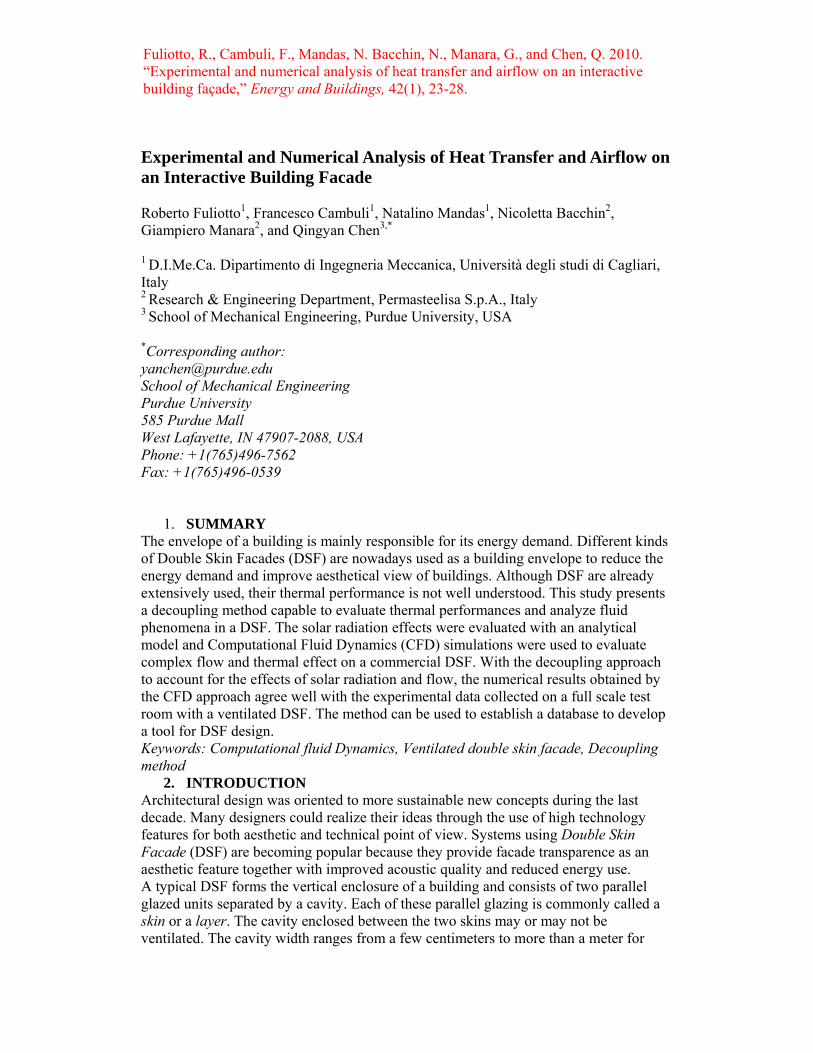
3) with a Venetian blinds shading device (VB), as shown in Fig. 2. The facade section dimensions were 3455 mm and 1350 mm with a float glass used for all the layers and a venetian blinder made with a 0.2 mm thick of curved aluminum sheet. Cavity ventilation was realized by small centrifugal fans located in the upper part of the section and working in suction mode. The air entered the DSF in a ventilation opening located in the bottom side of the frame. The right figure in Fig. 2 shows the DSF details of two consecutive floors. The exhaust opening is referred to the lower floor DSF while the ventilation opening is the inlet of the upper floor DSF. During the experimental measurements, the centrifugal fans generated a total flow rate of 40 m3/h per unit width of the facade. The experimental measurements provided the glass or Venetian blind surface temperatures, transmitted solar radiation, air flow rate and temperature in every air layers. Resistance Temperature Detectors (RTD) were employed to measure the glazing temperatures and the temperatures of the Venetian blinder. A pyranometer was used to collect information about the total solar radiation. Moreover, a meteorological station recorded outdoor climatic data and during the tests the same setpoints were maintained by a supervising control system. All the temperature data were sampled as a steady condition was reached. The main specifications of the measuring instruments are reported in Table 1 while a complete description of the experimental setup can be found in [20] and [21]. The temperature measurements were affected by external radiation and in general by installation manners. For temperature measurement inside the cavity, an uncertainty value of ±4°C was expected. . The sensor that measured the temperature of the external glass was exposed to a strong solar radiation. In this case the uncertainty of the measurement was high and an estimate of the value is difficult.
4. VALIDATION OF THE DECOUPLING APPROACH The experimental measurements were conducted on the DSF as depicted in Fig. 2. Table 2 presents four cases of different environmental conditions for which experimental data were collected in different days and time. In this table, the I is the external solar irradiation, Text the external ambient temperature, Tint the internal room temperature, and To the air temperature at the inlet of the DSF. In Table 2 are also reported the results from WIS calculations referred to the layers absorbed energy values. Since this facade was designed for temperate and tropical climate, the selected cases were to represent summer operative conditions. The temperature of the glazing surfaces and of the air inside the DSF cavities was measured in locations with three different heights (0.3 m, 0.9 m and 2.0 m from the bottom of the facade). Three different vertical

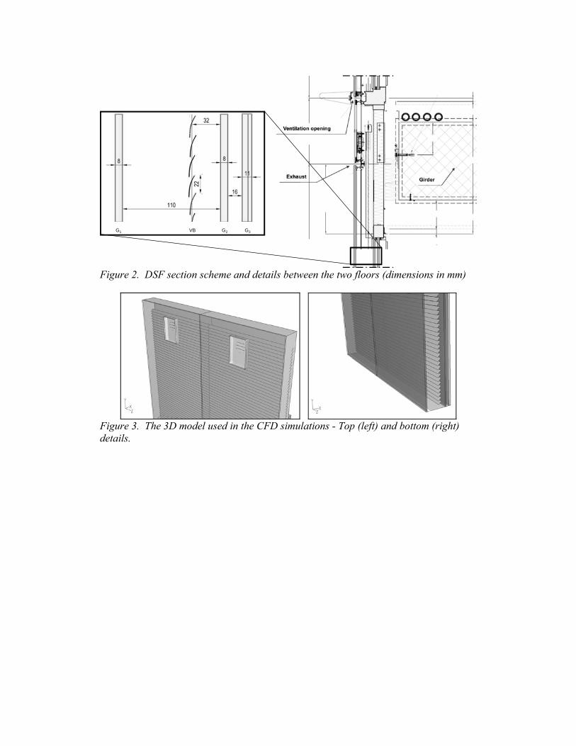
sections were also considered for measurements and no significant differences were found. The numerical simulations were performed on a simplified three–dimensional model of the DSF geometry omitting the bearing parts of the Venetian blinder. The slats were reproduced as shell surfaces and the curve shape was simplified by a flat rectangular surface. The three-dimensional model was further simplified in the air inlet and outlet sections where equivalent rectangular and circular sections were used, respectively, as shown in Figure 3. Also, equivalent area sections were used in the two-dimensional model for inlet and outlet. In the discretization of the 3D DSF cavities an unstructured tetrahedral mesh was used. The unstructured grids are suitable for a planned future development of the work that may use an arbitrary slat position and would take advantage of a fast grid generation. Cartesian meshes were used only for the solid zones. After a grid independence analysis, the three-dimensional model resulted in a mesh composed of 2.5×10⁶ cells (3×10⁵ cells for the two-dimensional model). Pressure inlet and exhaust-fan boundary conditions were used for inlet and outlet sections, respectively. The exhaust-fan boundary condition allows defining the typical pressure increase of the fan used for the forced ventilation of the DSF. The no-slip boundary condition was applied to all the walls. The flow rate generated by the two working fans was set through a fixed outward velocity boundary condition. At the inlet an intake fan boundary condition was used with zero gauge total pressure. The turbulence intensity at the inlet section was assumed to be 15% [22]. The results obtained with WIS software were elaborated to find the heat sources that reproduced the effect of the absorbed solar radiation by each solid zone. The heat sources were introduced in the CFD models to simulate the heat re-emitted at steady state from glazing layers and Venetian blinder slats (see Figure 1 for details). In order to obtain the correct y+ values, the mesh size was modified as suggested in [16], when using the standard wall functions for adequately solving thermal and flow boundary layers. The Rayleigh number based on the cavity height was about 1011 and the Reynolds number was 1×10⁴ based on the cavity width, which indicates a turbulent flow in the cavity.
5. RESULTS AND DISCUSSION As discussed in the introduction, a number of CFD simulations must be carried out to find a useful database in order to develop a simplified tool for designing DFS. The use of two dimensional models is suggested if one wants to reduce computational costs. In this section two and three-dimensional simulations are compared to evaluate the importance of the flow features and assess as the feasibility in using two–dimensional model for the thermal and fluid flows in the facade. The same operating conditions as shown in Table 1 have been investigated and the results have been compared to the experimental data. Figure 4 shows the flow field inside the cavity for Case 1, obtained with two- and three-dimensional simulations. Either the numerical models showed a vortex above the exhaust fan on the top of the DSF. The flow at about 1 m from the bottom separated into two streams, one moving through the Venetian blinder toward the internal cavity and forming a recirculating zone, the other moving upward through the DSF cavity. Figure 5 exhibits contours of the air temperature and non-dimensional air velocity in some horizontal sections of the DSF at different heights. The temperature distributions

look close to two-dimensional in all the sections, except in the regions near the inlet due to the flow recirculation underlined before, and at the top where the exhaust fans generated a complex flow. The horizontal velocity contours show a more uneven distribution in the upper part of the DSF, with strong three–dimensional effects. The velocity field in the DSF should significantly influence the heat transfer on the glass surface, but this does not happen in this case and the results can be considered as nearly two dimensional. Similar results were found for the other cases studied. Figure 6 compares the simulated and measured temperature distributions for all the simulated cases shown in Table 2 in three different heights of Y = 0.3 m, 0.9 m, and 2.0 m, respectively. In the 3D model the lines were at the vertical symmetry plane of the DSF. The agreement between the two- and three-dimensional simulations is generally good. A slight difference is found at Y = 0.9 m, probably due to the highly three-dimensional flow features in that region. The comparison between measured and computed results in a fairly agreement in the different cases studied. However, a significant discrepancy is found on the outer glazing, that is believed to come from both the difficulty in measuring accurately the external glass temperature and in controlling the external conditions. Shielded sensors were used to avoid solar radiation influence to glazing and cavity air temperature measurements. However the measured data of the external glazing show a probable shield malfunctioning. Moreover the wind conditions in the simulation may be different from the real ones that unfortunately were not measured.
6. CONCLUSIONS This paper demonstrated the feasibility of using a decoupling method to separate the radiative heat transfer effects on the thermal and flow features inside a ventilated DSF. The decoupling method allows studying the 3D flow and temperature distributions in a DSF in different conditions with reduced computing costs. The complex 3D features of the flow in the DSF cavities can be predicted with great details and the comparison between numerical results and experimental data for a commercial DSF shows a good agreement. Some discrepancies existed at the temperatures of the external glass, probably due to a lack of knowledge of the real operating conditions and to the intrinsic difficulty in accurate measurements. The results also show that even if the velocity fields were three dimensional and highly complicated, the mean thermal field can be considered as two dimensional in vertical planes perpendicular to the glazing. This is also confirmed by the 2D simulations, which produced results that correctly agreed with 3D simulations. The performance of the 2D model was analyzed and one may use the model to create a database of numerical results, with relatively low computational cost. This database can be used to generate a simple tool of DSF design.
7. REFERENCES [1] Saelens D., Carmeliet J. and Hens H. Energy Performance Assessment of Multiple Skin Facades. HVAC&R Research., vol. 9, nr. 2, pp.167-186, 2003. [2] Gratia E. and De Herde A. Greenhouse effect in double-skin façade, Energy and Buildings, 39 (2007) 199–211. [3] Park C., Augenbroe G., Messadi T., Thitisawat and M. Sadegh N. Calibration of a lumped simulation model for double-skin facade system, Energy and Building, 36 (2004) 1117–1130.

[4] Colombari M. and Balocco C. Thermal behavior of interactive mechanically ventilated double glazed facade: Non-dimensional analysis, Energy and Building, 38 (2005) 1–7. [5] Zollner A., Winter E.R.F. and Viskanta R. Experimental studies of combined heat transfer in turbulent mixed convection fluid flow in double skin facades, Int. J. of Heat and Mass Transfer, 45 (2002) 4401–4408. [6] Collins M., Harrison S.J., Naylor D. and Oosthuizen P.H. Heat transfer from an isothermal vertical surface with adjacent heated horizontal louvers: validation, Journal of Heat Transfer, 124(12) (2002) 1078–1087. [7] Collins M., Harrison S.J., Naylor D. and Oosthuizen P.H. Heat transfer from an isothermal vertical surface with adjacent heated horizontal louvers: numerical analysis, Journal of Heat Transfer, 124(12) (2002) 1072–1077. [8] Chen Q. and Srebric J. A procedure for verification, validation and reporting of indoor environment CFD analysis, HVAC&R Research, 8(2) (2002) 201–216. [9] Pappas A. and Zhai Z. Numerical investigation on thermal performance and correlation of double skin facade with buoyancy-driven airflow, Energy and Buildings, 40 (2007) 466-475. [10] Safer N., Woloszyn M. and Roux J.J. Three-dimensional simulation with a CFD tool of the airflow phenomena in single floor double-skin facade equipped with a venetian blind, Solar Energy, 79 (2005) 193-203. [11] Klems J.H., Warner J.L. and Kelley. A new method for predicting the solar heat gain of complex fenestration system. Final Report, Lawrence Berkeley Laboratory, USA, 1995. [12] Collins M. Convective heat transfer coefficients from an internal window surface and adjacent sunlit venetian blind, Energy and Building, 36 (2004) 309–318. [13] WIS. WIS User Guide. Advanced Windows Information System Project. http://www.windat.org/wis/html/index.html, 2006. [14] EN 410:2000. Glass in buildings – Determination of luminous and solar characteristics of glazing. European Committee for Standardization (CEN), 2000. [15] EN 673:2005. Glass in buildings – Determination of thermal transmittance (U-value) – Calculation method. European Committee for Standardization (CEN), 2005. [16] Chen Q. Comparison of different k-ε models for indoor air flow computations, Numerical Heat Transfer, Part B, 28 (1995) 353–369. [17] Zhang, Z., Zhang, W., Zhai, Z., and Chen, Q. “Evaluation of various turbulence models in predicting airflow and turbulence in enclosed environments by CFD: part-2: comparison with experimental data from literature,” HVAC&R Research, 13(6), 871-886, 2007. [18] Fluent. Fluent 6.3 User Guide. Fluent Inc., 2007. [19] Fuliotto R. Experimental and Numerical Analysis of Heat Transfer and Airflow on an Interactive Building Facade. Ph.D. thesis, Dipartimento di Ingegneria Meccanica, Università degli Studi di Cagliari, Italy, 2008. [20] Colombari M. Interactive wall tests - Test Rooms 5-12 – Preliminary results of full scale monitoring, Internal Report Permasteelisa Research & Engineering, 2002. [21] De Carli M. and Colombari M. Involucri edilizi trasparenti a ventilazione forzata: implicazioni impiantistiche. Atti del 58° Congresso Associazione Termotecnica Italiana, San Martino di Castrozza, Italy, 1825-1838, 2003.

[22] Fedorov A.G. and Viskanta R. Turbulent natural convection heat transfer in an asymmetrically heated, vertical parallel-plate channel, Journal of Heat and Mass Transfer, 40 (1997) 3849–3860.

a)
b)
Figure 1. The schematic of the decoupling method. ε: emissivity, α: absorbance, ρ: reflectance, τ: transmittance, I: incident solar radiation, θ: incidence angle, Ec: energy through convection. a) WIS step, b) CFD step
G1 VB G2 G3
Figure 2. DSF section scheme and details between the two floors (dimensions in mm)
Figure 3. The 3D model used in the CFD simulations - Top (left) and bottom (right) details.

Figure 4. The computed flow field inside the DSF cavity. a. Vector plots for the 2D model, upper (left) and lower side (right); b. Path lines (3D model)
a
b
]/[ sm

0.25 m
0.75 m
1.25 m
1.75 m
2.25 m
2.75 m
3.25 m
°C
0.25 m
0.75 m
1.25 m
1.75 m
2.25 m
2.75 m
3.25 m
ZZ
Figure 5. Temperature contours (top) and non-dimensional horizontal velocities (bottom) in the cross section at different heights of the DSF.

m3.0
m9.0
m0.2
Case 12600 mWI
CText 8.27
3D2D
Case 22566 mWI
CText 6.29
m3.0
m9.0
m0.2
Case 32691 mWI CText 4.32
3D2D
Case 42720 mWI
CText 4.32
Figure 6. Comparison of the temperature distributions in three different cross sections along the DSF. (dashed lines: three-dimensional simulations, solid lines: two-dimensional simulations, ■: experimental data)

Table 1. Measurement instrument accuracy Instrument Range Accuracy PT1000 temperature sensor -20…+100 °C 0.3 + 0.5% t (t in °C) Anemometer 0-20 m/s ± 5% FS Pyranometer 0…1300 W/m2 1.5% FS
Table 2. Cases studied – I: incident radiation, Text: external environment temperature,
Tint: room temperature, To: inlet air temperature, G: glass, VB: venetian blinder. I [W/m2] Text [°C] Tint [°C] To [°C]
Case 1 600 27.8 24.4 33.2 Case 2 556 29.6 25.0 37.3 Case 3 691 32.4 26.0 37.6 Case 4 720 32.4 26.5 39.9
Layer absorbed energy [W/m3]
G1 VB G2 G3
Case 1 1.52x10⁴ 1.73x10⁶ 2.85x10³ 1.42x10³
Case 2 1.41x10⁴ 1.60x10⁶ 2.64x10³ 1.31x10³
Case 3 1.75x10⁴ 1.99x10⁶ 3.28x10³ 1.63x10³
Case 4 1.83x10³ 2.07x10⁶ 3.42x10³ 1.70x10³


![Numerical Differentiation & Integration [0.125in]3.375in0 ...mamu/courses/231/Slides/CH04_4A.pdf · Numerical Differentiation & Integration Composite Numerical Integration I Numerical](https://img.pdfslide.us/doc/110x75/5b1fb63d7f8b9a112c8b4a5d/numerical-differentiation-integration-0125in3375in0-mamucourses231slidesch044apdf.jpg)