Embed Size (px)
Citation preview

ISSN 1520-295X
Experimental and Analytical Studies ofStructures Seismically Isolated with an
Uplift-Restraint Isolation System
by
Panayiotis C. Roussis and Michael C. ConstantinouUniversity at Buffalo, State University of New York
Department of Civil, Structural and Environmental EngineeringKetter Hall
Buffalo, New York 14260
Technical Report MCEER-05-0001
January 10, 2005
This research was conducted at the University at Buffalo, State University of New Yorkand was supported primarily by the Earthquake Engineering Research Centers Program
of the National Science Foundation under award number EEC-9701471.

NOTICEThis report was prepared by the University at Buffalo, State University of NewYork as a result of research sponsored by the Multidisciplinary Center for Earth-quake Engineering Research (MCEER) through a grant from the Earthquake Engi-neering Research Centers Program of the National Science Foundation under NSFaward number EEC-9701471 and other sponsors. Neither MCEER, associates ofMCEER, its sponsors, the University at Buffalo, State University of New York, norany person acting on their behalf:
a. makes any warranty, express or implied, with respect to the use of any infor-mation, apparatus, method, or process disclosed in this report or that such usemay not infringe upon privately owned rights; or
b. assumes any liabilities of whatsoever kind with respect to the use of, or thedamage resulting from the use of, any information, apparatus, method, or pro-cess disclosed in this report.
Any opinions, findings, and conclusions or recommendations expressed in thispublication are those of the author(s) and do not necessarily reflect the views ofMCEER, the National Science Foundation, or other sponsors.
Experimental and Analytical Studies of StructuresSeismically Isolated with an Uplift-Restraint
Isolation System
by
Panayiotis C. Roussis1 and Michael C. Constantinou2
Publication Date: January 10, 2005Submittal Date: October 19, 2004
Technical Report MCEER-05-0001
Task Number 2.4a and 03/2.2
NSF Master Contract Number EEC-9701471
1 Postdoctoral Associate, Department of Civil, Structural and Environmental Engi-neering, University at Buffalo, State University of New York
2 Professor, Department of Civil, Structural and Environmental Engineering, Univer-sity at Buffalo, State University of New York
MULTIDISCIPLINARY CENTER FOR EARTHQUAKE ENGINEERING RESEARCHUniversity at Buffalo, State University of New YorkRed Jacket Quadrangle, Buffalo, NY 14261

iii
Preface
The Multidisciplinary Center for Earthquake Engineering Research (MCEER) is a nationalcenter of excellence in advanced technology applications that is dedicated to the reductionof earthquake losses nationwide. Headquartered at the University at Buffalo, StateUniversity of New York, the Center was originally established by the National ScienceFoundation in 1986, as the National Center for Earthquake Engineering Research (NCEER).
Comprising a consortium of researchers from numerous disciplines and institutionsthroughout the United States, the Center’s mission is to reduce earthquake losses throughresearch and the application of advanced technologies that improve engineering, pre-earthquake planning and post-earthquake recovery strategies. Toward this end, the Centercoordinates a nationwide program of multidisciplinary team research, education andoutreach activities.
MCEER’s research is conducted under the sponsorship of two major federal agencies: theNational Science Foundation (NSF) and the Federal Highway Administration (FHWA),and the State of New York. Significant support is derived from the Federal EmergencyManagement Agency (FEMA), other state governments, academic institutions, foreigngovernments and private industry.
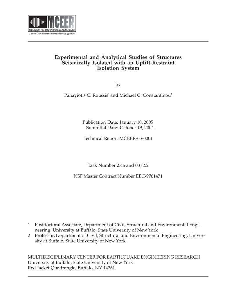
MCEER’s NSF-sponsored research objectives are twofold: to increase resilience by devel-oping seismic evaluation and rehabilitation strategies for the post-disaster facilities andsystems (hospitals, electrical and water lifelines, and bridges and highways) that societyexpects to be operational following an earthquake; and to further enhance resilience bydeveloping improved emergency management capabilities to ensure an effective re-sponse and recovery following the earthquake (see the figure below).
-
Infrastructures that Must be Available /Operational following an Earthquake
Intelligent Responseand Recovery
Hospitals
Water, GasPipelines
Electric PowerNetwork
Bridges andHighways
More
Earthquake
Resilient Urban
Infrastructure
System
Cost-
Effective
Retrofit
Strategies
Earthquake Resilient CommunitiesThrough Applications of Advanced Technologies

iv
A cross-program activity focuses on the establishment of an effective experimental andanalytical network to facilitate the exchange of information between researchers locatedin various institutions across the country. These are complemented by, and integratedwith, other MCEER activities in education, outreach, technology transfer, and industrypartnerships.
This report describes the development of a novel uplift-prevention Friction Pendulum isolator called
the XY-FP. It presents the principles of operation and mathematical model of the XP-FP isolator,
describes its mechanical behavior through testing of a single isolator, and demonstrates its effectiveness
through testing of a quarter-scale steel-frame model structure. The computer program 3D-BASIS-ME
was modified to include an element representative of the mechanical behavior of the new XY-FP
isolator, and the validity and accuracy of analytical methods to predict its behavior is assessed. The
study shows that the XY-FP isolator provides effective uplift prevention regardless of the state of
displacement in the bearing, allows for decoupling of the bi-directional horizontal motion along two
orthogonal directions, and has the capability to provide distinct stiffness and energy dissipation along
the principal directions of the bearing. In addition, by encompassing much less structural material, the
isolator offers a lighter and more economical alternative to the standard Friction Pendulum bearing.
Moreover, it provides an architecturally flexible solution in terms of integration into a structural
system when space considerations are important.
ABSTRACT
Notwithstanding its pervasive influence on seismic-resistant engineering, the efficacy of
seismic isolation in structures subjected to strong ground excitation, including near-fault
effects, is potentially compromised by excessive overturning moments capable of
inducing undesirable uplift or tension in the isolation bearings. This report aims at
extending the scope of seismic isolation by studying a novel sliding isolation bearing,
denoted as XY-FP, that is capable of sustaining tensile forces, thereby preventing uplift.
This report primarily focuses on: (i) introducing the concept and establishing the
principles of operation and mathematical model of the new XY-FP isolator; (ii)
developing an understanding of the mechanical behavior of the XY-FP isolator through
testing of a single isolator; (iii) generating experimental results through earthquake
simulator testing of a quarter-scale five-story model to validate the effectiveness of these
isolators in preventing uplift; (iv) modifying the computer program 3D-BASIS-ME to
include an element representative of the XY-FP isolator; and (v) assessing the validity
and accuracy of analytical methods to predict the behavior of such systems.
The XY-FP isolation bearing consists of two opposing concave beams interconnected
through an element which permits tension to develop in the bearing, thereby preventing
uplift. Salient properties that distinguish the XY-FP isolator from the conventional
Friction Pendulum (FP) isolator include: (i) effective uplift restraint regardless of the
state of displacement in the bearing; (ii) decoupling of the bi-directional horizontal
motion along two orthogonal directions; and (iii) capability of providing distinct stiffness
and energy dissipation along the principal directions of the bearing.
To demonstrate the validity of the concept and provide evidence for the effectiveness of
the XY-FP isolator in uplift restraint, an extensive testing program on the earthquake
simulator at the University at Buffalo was conducted on a slender quarter-scale five-story
base-isolated model structure. The isolation system, comprised of four XY-FP isolators,
was installed beneath a base and rotated for testing in different directions. The range of
tests conducted represent the only available experimental data on XY-FP isolators and
form the basis for comparison with and validation of the analytical predictions.
v
A comprehensive mathematical model capable of accommodating the mechanical
behavior of the XY-FP isolator was developed and implemented in program 3D-BASIS-
ME. The new element representing the XY-FP isolator was synthesized by two
independent uniaxial hysteretic elements allowing different frictional interface properties
along the principal isolator directions under compressive or tensile isolator normal force.
Contrary to the element representing the conventional FP isolator, the new element is
capable of developing tension. This enhancement augments the potential of 3D-BASIS-
ME by providing a versatile tool for analysis of seismically isolated structures with XY-
FP isolators.
The dynamic response of the five-story seismically isolated model was predicted
analytically using 3D-BASIS-ME. The validity of the analytical model, with reference to
the newly introduced element representing the XY-FP isolator, was investigated by
comparison of analytical predictions with experimental results.
Finally, a case study involving nonlinear response-history analysis of a seismically
isolated structure subjected to bi-directional horizontal seismic excitation is presented to
assess the impact of XY-FP isolator on the response of a real structure.
vi

ACKNOWLEDGEMENTS
Financial support for this project was provided by the Multidisciplinary Center for
Earthquake Engineering Research (Task 2.4a and Task 03/2.2) and Earthquake Protection
Systems, Inc., Vallejo, CA. This support is gratefully acknowledged.
The assistance of Professor Panagiotis Tsopelas of the Catholic University of America in
modifying program 3D-BASIS-ME is also gratefully acknowledged.
This report is nearly identical to the doctoral dissertation of Panayiotis C. Roussis. The
dissertation committee consisted of Professors Michael C. Constantinou (Chair), Andrei
M. Reinhorn, Andrew S. Whittaker, and Andres Soom (outside reviewer, Department of
Mechanical and Aerospace Engineering).
vii

ix
TABLE OF CONTENTS
SECTION TITLE PAGE 1 INTRODUCTION ................................................................................................. 1 1.1 Background........................................................................................................... 1 1.2 Motivation ............................................................................................................ 5 1.3 Objective............................................................................................................... 6 1.4 Outline .................................................................................................................. 6
2 DESCRIPTION AND MATHEMATICAL MODEL OF XY-FP ISOLATOR ............................................................................................................ 9
2.1 Introduction .......................................................................................................... 9 2.2 Principles of Operation......................................................................................... 9 2.3 Mathematical Model............................................................................................. 10
3 TESTING OF XY-FP ISOLATOR ...................................................................... 19 3.1 Introduction .......................................................................................................... 19 3.2 Theoretical Background ....................................................................................... 19 3.3 Testing Machine Description................................................................................ 21 3.4 Testing Program ................................................................................................... 21 3.5 Test Results .......................................................................................................... 24
4 MODEL FOR EARTHQUAKE SIMULATOR TESTING ............................... 31 4.1 Introduction .......................................................................................................... 31 4.2 Model Description ................................................................................................ 31 4.3 Pushover Analysis ................................................................................................ 34 4.4 Instrumentation..................................................................................................... 34 4.5 Testing Program ................................................................................................... 36 4.6 Identification of Dynamic Characteristics of Model Structure............................. 48
5 EARTHQUAKE SIMULATOR TESTING RESULTS ..................................... 55 5.1 Introduction .......................................................................................................... 55 5.2 Test Results .......................................................................................................... 55 5.3 Interpretation of Results ....................................................................................... 57
6 MODIFICATION OF PROGRAM 3D-BASIS-ME ........................................... 69 6.1 Introduction .......................................................................................................... 69 6.2 Overview of Program 3D-BASIS......................................................................... 69 6.3 Enhancements Introduced in Program 3D-BASIS-ME........................................ 71 6.3.1 New Hysteretic Element for XY-FP Isolator ................................................. 71 6.3.2 Account for Initial Non-zero Displacement of the Isolators .......................... 75 6.3.3 A More Accurate Description of the Additional Bearing Axial Forces
due to Overturning Moment Effects .............................................................. 75
7 ANALYTICAL PREDICTION OF RESPONSE................................................ 79 7.1 Introduction .......................................................................................................... 79 7.2 Analytical Model .................................................................................................. 79 7.3 Comparison of Experimental and Analytical Results........................................... 80

TABLE OF CONTENTS (Continued)
SECTION TITLE PAGE
x
8 A CASE STUDY .................................................................................................... 87 8.1 Introduction .......................................................................................................... 87 8.2 Description of Seismically Isolated Structure ...................................................... 87 8.3 Analytical Model in SAP2000 and 3D-BASIS-ME ............................................. 89 8.4 Analysis Results ................................................................................................... 93
9 SUMMARY AND CONCLUSIONS .................................................................... 111
10 REFERENCES....................................................................................................... 117
APPENDIX A PUSHOVER ANALYSIS OF 5-STORY MODEL FRAME........................... *
APPENDIX B EXPERIMENTAL RESULTS FOR THE 5-STORY MODEL STRUCTURE SEISMICALLY ISOLATED WITH XY-FP ISOLATORS ....................................................................................................... *
APPENDIX C COMPARISON OF ANALYTICAL AND EXPERIMENTAL RESULTS FOR THE 5-STORY MODEL STRUCTURE SEISMICALLY ISOLATED WITH XY-FP ISOLATORS ........................... *
APPENDIX D COMPARISON OF ANALYTICAL PREDICTIONS OF SAP2000 AND 3D-BASIS-ME FOR THE CASE-STUDY STRUCTURE SEISMICALLY ISOLATED WITH SOLELY FP ISOLATORS ................. *
APPENDIX E COMPARISON OF 3D-BASIS-ME ANALYTICAL PREDICTIONS OF THE CASE-STUDY STRUCTURE SEISMICALLY ISOLATED WITH (a) SOLELY FP ISOLATORS AND (b) BOTH FP AND XY-FP ISOLATORS ....................................................................................................... *
* The appendices are provided on the enclosed CD.

xi
LIST OF FIGURES
FIGURE TITLE PAGE 1-1 Uplift-restraint system used on Excel Minami-Koshigaya building,
Koshigaya City, Japan (Sumitomo Construction, 1990) ...................................... 2 1-2 Displacement-control, uplift-restraint device incorporated in elastomeric
bearing (Kelly et al., 1987)................................................................................... 3 1-3 Uni-directional flat sliding bearing with uplift-restraint device
(Nagarajaiah et al., 1992) ..................................................................................... 4 1-4 View of uni-directional FP bearing with uplift restraint installed at the
San Francisco approach to the Oakland Bay Bridge ............................................ 4 1-5 View of the novel uplift-prevention XY-FP isolator ............................................ 5 2-1 Three-dimensional view of the uplift-restraint XY-FP isolator............................ 9 2-2 Plan view of XY-FP isolator in its deformed position.......................................... 11 2-3 Free body diagrams of (a) connecting slider for motion along local
axis 1, and (b) upper concave beam for motion along local axis 2, under compressive and tensile normal force ........................................................ 12
2-4 Effect of lateral force interaction in XY-FP isolator ............................................ 15 2-5 Force-displacement relation of XY-FP isolator under (a) compressive and (b) tensile normal force.................................................................................. 16 2-6 Behavior of system of two isolators: FP vs. XY-FP isolators .............................. 18 3-1 Dependency of coefficient of friction on velocity ................................................ 20 3-2 Variation of friction parameter maxf with pressure.............................................. 20 3-3 Schematic of isolator testing apparatus ................................................................ 21 3-4 Photograph of isolator testing apparatus............................................................... 22 3-5 Two-dimensional view of the uplift-restraint XY-FP isolator used in
this study............................................................................................................... 22 3-6 Views of XY-FP isolator during testing in 0º , 45º , and 90º orientation........... 23 3-7 Imposed displacement history for XY-FP isolator testing.................................... 23 3-8 Recorded normalized force-displacement loops of XY-FP isolator
demonstrating the effect of (a) normal force, and (b) sliding velocity ................. 25 3-9 Dependency of coefficient of friction on velocity of sliding................................ 27 3-10 Recorded normalized force-displacement loops of XY-FP isolator
for different isolator orientations for (a) compressive and (b) tensile normal load........................................................................................................... 28
4-1 Photograph of tested five-story isolated model structure on the seismic
simulator at the University at Buffalo .................................................................. 32 4-2 Schematic of tested 5-story isolated model structure ........................................... 33 4-3 Member cross sections for model structure .......................................................... 33 4-4 Instrumentation diagram for the 5-story test frame .............................................. 35 4-5 Histories and response spectra of shake table motion for El Centro S00E
200% excitation .................................................................................................... 39 4-6 Histories and response spectra of shake table motion for Taft N21E
400% excitation .................................................................................................... 40

LIST OF FIGURES (Continued)
FIGURE TITLE PAGE
xii
4-7 Histories and response spectra of shake table motion for Newhall 90 100% excitation.................................................................................................... 41
4-8 Histories and response spectra of shake table motion for Newhall 360 100% excitation.................................................................................................... 42
4-9 Histories and response spectra of shake table motion for Symlar 90 100% excitation.................................................................................................... 43
4-10 Histories and response spectra of shake table motion for Kobe N-S 100% excitation.................................................................................................... 44
4-11 Histories and response spectra of shake table motion for Pacoima S74W 100% excitation.................................................................................................... 45
4-12 Histories and response spectra of shake table motion for Pacoima S16E 100% excitation.................................................................................................... 46
4-13 Histories and response spectra of shake table motion for Hachinohe N-S 100% excitation.................................................................................................... 47
4-14 Floor transfer function amplitudes for banded (0-40 Hz) white noise base excitation ...................................................................................................... 52
4-15 Schematic of influential mode shapes of fixed-based model structure................. 53 5-1 Typical isolation system displacement history ..................................................... 56 5-2 History of permanent displacements from testing in different isolator
orientations ........................................................................................................... 62 5-3 Experimental results in El Centro S00E 200% for bearing orientation
of 0º ..................................................................................................................... 63 5-4 Experimental results in Newhall 360 100% for bearing orientation
of 0º .................................................................................................................... 64 5-5 Experimental results in Newhall 360 100% for bearing orientation
of 90º ................................................................................................................... 65 5-6 Experimental results in Newhall 360 100% for bearing orientation
of 45º ................................................................................................................... 66 5-7 Comparison of experimental results in Pacoima S74W 100% and
Pacoima S74W+Vertical 100% excitations for bearing orientation of 0º ........... 67 6-1 Force interaction curves for XY-FP and FP isolators........................................... 73 6-2 Definition of overturning moments OVMX and OVMY, and additional
force FOVM ......................................................................................................... 74 7-1 Comparison of experimental and analytical results for bearing
orientation of 0º for 100% Kobe N-S excitation.................................................. 82 7-2 Comparison of experimental and analytical results for bearing
orientation of 0º for 100% Newhall 360+vertical excitation ............................... 83 7-3 Comparison of experimental and analytical results for bearing
orientation of 90º for 100% Newhall 360+vertical excitation.............................. 84 7-4 Comparison of experimental and analytical results for bearing
orientation of 45º for 100% Sylmar 90+vertical excitation ................................. 85

LIST OF FIGURES (Continued)
FIGURE TITLE PAGE
xiii
7-5 Comparison of experimental and analytical results for bearing orientation of 45º for 100% Newhall 360+vertical excitation ............................. 86
8-1 View of the new Acropolis Museum in Athens, Greece directly at the foot of the
Acropolis. (http://www.archpedia.com/Projects-Bernard-Tschumi_01.html) ..... 88 8-2 Plan view of isolated structure.............................................................................. 88 8-3 Schematic of SAP2000 model of the seismically isolated building
used in the case study ........................................................................................... 90 8-4 Plan view of the base of the building model in SAP2000 showing the spatial
distribution of seismic isolation bearings ............................................................. 90 8-5 Comparison of SAP2000 and 3D-BASIS-ME generated results in terms
of superstructure response in X direction for the model with 94 FP isolators in scaled (factor 4.5) Lower California 270-180 excitation................... 95
8-6 Comparison of SAP2000 and 3D-BASIS-ME generated results in terms of superstructure response in Y direction for the model with 94 FP isolators in scaled (factor 4.5) Lower California 270-180 excitation................... 96
8-7 Comparison of SAP2000 and 3D-BASIS-ME generated results in terms of isolation system response in X direction for the model with 94 FP isolators in scaled (factor 4.5) Lower California 270-180 excitation................... 97
8-8 Comparison of SAP2000 and3D-BASIS-ME generated results in terms of isolation system response in Y direction for the model with 94 FP isolators in scaled (factor 4.5) Lower California 270-180 excitation................... 98
8-9 Comparison of SAP2000 and 3D-BASIS-ME generated results in terms of response of bearing No. 55 in X direction for the model with 94 FP isolators in scaled (factor 4.5) Lower California 270-180 excitation................... 99
8-10 Comparison of SAP2000 and 3D-BASIS-ME generated results in terms of response of bearing No. 55 in Y direction for the model with 94 FP isolators in scaled (factor 4.5) Lower California 270-180 excitation................... 100
8-11 Number of bearings in uplift per time instant....................................................... 102 8-12 Comparison of 3D-BASIS-ME generated results in terms of superstructure
response in X direction between the model with 94 FP isolators and the model with 25 XY-FP + 69 FP isolators in scaled (factor 2.0) El Centro 180-270 excitation ................................................................................................ 103
8-13 Comparison of 3D-BASIS-ME generated results in terms of superstructure response in Y direction between the model with 94 FP isolators and the model with 25 XY-FP + 69 FP isolators in scaled (factor 2.0) El Centro 180-270 excitation ................................................................................................ 104
8-14 Comparison of 3D-BASIS-ME generated results in terms of isolation system response in X direction between the model with 94 FP isolators and the model with 25 XY-FP + 69 FP isolators in scaled (factor 2.0) El Centro 180-270 excitation................................................................................ 105
8-15 Comparison of 3D-BASIS-ME generated results in terms of isolation system response in Y direction between the model with 94 FP isolators and the model with 25 XY-FP + 69 FP isolators in scaled (factor 2.0) El Centro 180-270 excitation................................................................................ 106

LIST OF FIGURES (Continued)
FIGURE TITLE PAGE
xiv
8-16 Comparison of 3D-BASIS-ME generated results in terms of response of bearing No. 67 in X direction between the model with 94 FP isolators and the model with 25 XY-FP + 69 FP isolators in scaled (factor 2.0) El Centro 180-270 excitation................................................................................ 107
8-17 Comparison of 3D-BASIS-ME generated results in terms of response of bearing No. 67 in Y direction between the model with 94 FP isolators and the model with 25 XY-FP + 69 FP isolators in scaled (factor 2.0) El Centro 180-270 excitation................................................................................ 108

xv
LIST OF TABLES
TABLE TITLE PAGE 3-1 Values of parameters used in isolator testing program......................................... 23 3-2 Parameters used in calibration of the equation describing the dependency
of coefficient of friction on velocity (Equation (3-1)).......................................... 26 4-1 Scale factors for model structure .......................................................................... 34 4-2 List of data acquisition channels (with reference to Figure 4-4) .......................... 36 4-3 List of earthquake motions and their characteristics in prototype scale ............... 38 4-4 List of earthquake simulator tests conducted on the 5-story model
structure ................................................................................................................ 48 4-5 Dynamic characteristics of fixed-based model structure...................................... 53 5-1 Experimentally recorded peak structure response for isolator angle of 0º .......... 58 5-2 Experimentally recorded peak structure response for isolator angle of 90º ........ 59 5-3 Experimentally recorded peak structure response for isolator angle of 45º ........ 60 8-1 Properties of analyzed structure............................................................................ 91 8-2 Periods of free vibration of the fixed-base structure ............................................ 91 8-3 Selected ground motions and scale factors used in analysis................................. 93 8-4 FP isolators undergoing uplift identified from 3D-BASIS-ME analysis.............. 101


SECTION 1
INTRODUCTION
1.1 Background
Having found a plethora of applications in many parts of the world, seismic isolation has
emerged as a pragmatic approach to providing earthquake resistance to structural
systems. Research developments in the areas of analytical modeling and experimental
validation techniques paralleled by notable advances of seismic isolation device
hardware, have provided the impetus for the increasing acceptance of seismic isolation.
The fundamental principle underlying seismic isolation involves decoupling the structure
from the damaging horizontal ground motion by means of additional flexibility and
energy dissipation capability, thereby mitigating the severity of structural vibration and
damage during seismic events (Naeim and Kelly, 1999; Skinner et al., 1993). Typified by
either elastomeric or sliding bearings, the application of seismic isolation systems can
result in significant reduction of the inertial forces developed in a structure during a
severe earthquake. While this entails a desired reduction of the sustained overturning
moments, the uplift forces may still be potentially large enough to be of concern, on
account of the inherent incapacity of elastomeric and sliding bearings to resist uplift
forces.
In fact, a variety of conditions may contribute to the development of either tensile forces
(in bolted rubber bearings) or uplift (in sliding bearings and doweled rubber bearings).
These include slender structures with a large height-to-width aspect ratio, certain types of
bridges with large ratio of height of the centroidal axis to the distance between the
bearings, and bearings below braced columns or stiff walls.
Tensile forces or uplift in isolation bearings may produce, under certain conditions,
detrimental effects in the form of local instability or rupture of elastomeric bearings, and
damage on sliding bearings due to large compressive forces upon impact following uplift.
Loss of contact and impact on return can yield higher-mode response and large axial
forces in columns.
1

A number of uplift-restraint seismic isolation systems have been proposed and some have
been implemented. A brief account of these systems and their limitations is given below.
• An uplift-restraint system consisting of two massive orthogonal steel arms (Figure
1-1) was developed by Sumitomo Construction in Japan and used on the Excel
Minami-Koshigaya 10-story building in Koshigaya City (Sumitomo Construction,
1990). The opposing arms, connected to the superstructure and foundation, interlock
upon uplift equal to the 1-cm default clearance, thus preventing further uplift of the
superstructure. The system has not been tested and its impact on the behavior of the
isolation system has not been assessed to the knowledge of the author.
Uplift-restraint system
Figure 1-1: Uplift-restraint system used on Excel Minami-Koshigaya building, Koshigaya City, Japan (Sumitomo Construction, 1990).
• A mechanism that claims to provide uplift restraint and displacement control for
elastomeric bearings was described by Kelly et al. (1987) and Griffith et al. (1988a,
1988b, 1990). The system has been studied in earthquake simulator tests of
seismically isolated structures. Incorporated within a central hole in elastomeric
bearings, the device consists of two high-strength bolts contained in a cylindrical
sleeve that allows a certain amount of free movement of the bolts (Figure 1-2). This
mechanism can be activated only when the bearing undergoes substantial uplift or
substantial lateral deformation. In effect, the system does not prevent uplift but rather
2

may restrict uplift to a limit, which is too large due to the dual function of the
mechanism to also provide lateral displacement control. In addition to this limitation,
the mechanism is hidden within the bearing inhibiting inspection without removal and
disassembly of the bearing.
Figure 1-2: Displacement-control, uplift-restraint device incorporated in elastomeric bearing (Kelly et al., 1987).
• The technique of prestressing for the prevention of tensile force and uplift in isolators
was described in Logiadis (1996) and Kasalanati and Constantinou (1999).
Prestressing tendons were used to develop sufficient additional compressive force on
the bearings so that tension or uplift was prevented. This system, while effective and
predictable in behavior as demonstrated by testing, is complex and may impact the
performance of the isolation system.
• Uni-directional flat sliding bearings encompassing uplift-restraint devices as shown in
Figure 1-3 were tested by Nagarajaiah et al. (1992) in an isolation system together
with helical steel springs for providing restoring force. The same concept in uplift
prevention may be used in sliding bearings with a curved surface as it has been done
at the San Francisco approach to the Oakland Bay Bridge, where uni-directional FP
bearings are utilized (Figure 1-4). It may be noted that this uplift restrainer allows for
some uplift before it engages due to the cylindrical shape of the sliding surface.
Extension of this type of restrainer to multi-directional sliding bearings is feasible if
the displacement demand is low.
3

Figure 1-3: Uni-directional flat sliding bearing with uplift-restraint device (Nagarajaiah et al., 1992).
Figure 1-4: View of uni-directional FP bearing with uplift restraint installed at the San Francisco approach to the Oakland Bay Bridge.
Studied in this report is a novel uplift-prevention Friction Pendulum isolator, abbreviated
hereafter as XY-FP (Figure 1-5). The XY-FP isolation bearing has the following unique
properties: (i) it provides effective uplift prevention regardless of the state of
displacement in the bearing; (ii) it allows for decoupling of the bi-directional horizontal
motion along two orthogonal directions; and (iii) it has the capability of providing
distinct stiffness and energy dissipation along the principal directions of the bearing.
Additional benefits can be derived from the unique morphology of the new bearing. In
particular, by encompassing much less structural material, the isolator offers a lighter and
more economical alternative to the standard Friction Pendulum (FP) bearing. Moreover,
it provides an architecturally flexible solution in terms of integration into a structural
system for cases where space considerations are important.
4

Figure 1-5: View of the novel uplift-prevention XY-FP isolator.
1.2 Motivation
Thus far, seismically isolated structures have been designed so that uplift in sliding
bearings or tension in elastomeric bearings is avoided. To accommodate this practice,
changes to the structural system above the isolators were often deemed necessary.
However, such changes may be extensive as illustrated in the Oakland City Hall (Honeck
et al., 1993) with the construction of a large truss at the basement level to “spread out”
the reactions, and in the Corinth Canal Bridges (Constantinou, 1998) with use of
counterweights at the abutments.
Uplift or tension in bearings is often undesirable due to concerns for failure of
elastomeric bearings in tension or concerns for large bearing compressive forces on
engagement following uplift (which may include impact effects).
Recent applications of seismic isolation in California deal with substantial seismic
loading, which includes near-fault effects, and desire to achieve specific performance
levels. Tension or uplift in isolation bearings is often encountered. Cost, architectural and
functionality constraints prevent the modification of the structural system to avoid uplift
or tension in bearings. Accordingly, a need evolved to develop acceptable isolators with
tension (or uplift restraint) capability and to better understand the phenomena of uplift or
tension of isolators and their impact on the performance of structural and non-structural
systems.
Prompted by the need to respond to these developments, this research aims at extending
the scope of seismic isolation by studying a novel uplift-restraint isolation bearing. With
5

the isolators capable of sustaining tension, the application of seismic isolation could be
widely facilitated.
1.3 Objective
The principal objectives of this report can be summarized as follows: (i) to introduce the
concept and establish the principles of operation and mathematical model of the newly
introduced XY-FP isolator; (ii) to gain an understanding of the mechanical behavior of
the XY-FP isolator through testing of a single isolator; (iii) to generate experimental
results through testing of a quarter-scale steel-frame model structure on the earthquake
simulator at the University at Buffalo to validate the effectiveness of these isolators in
preventing uplift; (iv) to modify the computer program 3D-BASIS-ME to include an
element representative of the mechanical behavior of the new XY-FP isolator; and (v) to
assess the validity and accuracy of analytical methods to predict the behavior of such
systems.
1.4 Outline
This report is thematically organized into nine sections. The introductory section presents
background information and embodies the prime motivation, objectives, and organization
of the report.
Section 2 describes the concept and presents the underlying principles of operation of the
XY-FP isolator. A distinguishing feature of the new isolator is its capability to prevent
uplift through a mechanism which permits tension to develop in the bearing. Further, the
mathematical model for the new XY-FP isolator is formulated upon development of the
force-displacement constitutive relationship.
Section 3 presents experimental results from tests of a single XY-FP isolator conducted
using the isolator testing machine currently available at the Structural Engineering and
Earthquake Simulation Laboratory of the University at Buffalo. This section aims at
gaining a better understanding of the behavior and mechanical properties of the isolators
at hand.
Section 4 provides information on the testing program on the earthquake simulator at the
6
University at Buffalo. The program involved a quarter-scale five-story base-isolated
model structure subjected to a number of recorded ground motions having a broad range
of frequency contents and amplitudes. The properties and dynamic characteristics of the
non-isolated superstructure model were identified and are presented in this section. The
isolation system, installed beneath a rigid base, was comprised of four XY-FP isolators.
The instrumentation scheme employed in the testing program along with a complete list
of tests conducted are presented.
Section 5 includes a representative sample of experimental results from the earthquake
simulator testing program described in Section 4. Interpretation of these results provides
evidence for the effectiveness of the XY-FP isolator in uplift prevention. In addition, the
experimental response forms the basis for comparison with and validation of the
analytical predictions presented in Section 7.
Section 6 outlines the modifications made in computer program 3D-BASIS-ME
(Tsopelas, et al., 1994). While maintaining the main features of the program, the
following enhancements are incorporated: (i) a new hysteretic element capable of
modeling the behavior of the new XY-FP isolator; (ii) capability of accounting for initial
non-zero displacement of the isolators; and (iii) a more accurate description of the
additional bearing axial forces due to overturning effects.
Section 7 is devoted to the analytical prediction of response. The validity of the analytical
model, with reference to the newly introduced element representing the XY-FP isolator,
was investigated by comparison of analytical predictions with experimental results. The
good agreement attests to the accuracy of the analytical model even under extreme
dynamic conditions.
Section 8 presents a case study which involves analysis of a seismically isolated structure
and assessment of the impact of XY-FP bearing on its response. Nonlinear response-
history analysis of the seismically isolated structure subjected to bi-directional horizontal
seismic excitation was performed using programs SAP2000 and 3D-BASIS-ME. First, a
comparison is made between results from SAP2000 and 3DBASIS-ME analysis based on
an isolation system model consisting solely of FP isolators. Moreover, results from
3DBASIS-ME analysis of the model with only FP isolators are compared to results from
7
analysis of the model with isolators prone to uplift being replaced with XY-FP isolators.
Section 9 presents a summary of key findings and conclusions drawn from this report.
The report is further augmented by five appendices. Appendix A presents information on
the pushover analysis of the five-story frame model considered in this study. The
complete presentation of experimental results of the five-story base-isolated model
structure from the earthquake simulator testing program is given in Appendix B.
Appendix C presents comparisons of experimental and 3D-BASIS-ME analytical results
for the isolated structure at hand. Appendices D and E include comparison of analytical
results pertaining to the case study considered in this report. Presented in Appendix D are
results generated by programs SAP2000 and 3DBASIS-ME from analyses of the model
with solely FP isolators. In Appendix E results from 3DBASIS-ME analysis of the model
with only FP isolators are compared to results from analysis of the model with isolators
prone to uplift being replaced with XY-FP isolators.
8

SECTION 2
DESCRIPTION AND MATHEMATICAL MODEL OF XY-FP
ISOLATOR
2.1 Introduction
A novel uplift-restraint Friction Pendulum isolator, abbreviated hereafter as XY-FP, is
studied in this report. This section introduces the principles of operation and establishes a
mathematical model of the new XY-FP isolator.
2.2 Principles of Operation
While a conventional Friction Pendulum in principle (Zayas et al., 1987; Mokha et al.,
1988), the new isolator consists of two opposing concave stainless steel-faced beams
forming a bi-directional (XY) motion mechanism (Figure 2-1). Under the imposed
constraint to remain mutually perpendicular (except for small rotation about the vertical
axis), the two beams can move independently relative to each other. In particular, the
kinematics involved consists of two independent components: (1) sliding of the upper
beam along the (fixed) lower beam; and (2) sliding of the upper beam with respect to the
connecting block in a direction perpendicular to the axis of the lower beam. Moreover,
the XY-FP isolator is designed for the capability of small rotation (approximately 4
degrees) about the vertical axis to accommodate torsion of the structure.
Figure 2-1: Three-dimensional view of the uplift-restraint XY-FP isolator.
9

In addition to geometric considerations, a distinguishing feature of the new XY-FP
isolator is its capability to prevent uplift. The configuration through which the two parts
are interconnected permits tension to develop in the bearing, thereby preventing uplift.
The XY-FP isolation bearing has the following unique properties: (1) it provides effective
uplift prevention; (2) it allows for decoupling of the bi-directional motion along two
orthogonal directions; and (3) it has the capability of providing distinct stiffness and
energy dissipation along the principal horizontal directions of the bearing. The latter
property can be exploited, for example, in bridges where different response in terms of
displacement may be desired along the longitudinal and transverse directions. Neither a
conventional FP nor a rubber bearing can offer feasible displacement control in
orthogonal directions. Additional benefits can be derived from the unique morphology of
the new bearing. In particular, by encompassing much less structural material, the XY-FP
isolator offers a lighter and more economical alternative to the FP bearing. Moreover, it
provides an architecturally flexible solution in terms of integration into a structural
system for cases where space consideration is important, e.g., where the cylindrical shape
of the conventional FP bearing becomes awkward or problematic under walls, as in the
proximity of elevators and stairs.
2.3 Mathematical Model
In formulating the mathematical model for the new XY-FP isolator, separate force-
displacement constitutive relationships were developed discretely for compressive and
tensile bearing normal load. It is also important to note that the bi-directional motion
admits decoupling along the principal axes of the bearing. Accordingly, the constitutive
relationship can be conveniently stated with respect to the local co-ordinate system.
Figure 2-2 depicts a plan view of the bearing, whose orientation is defined by the angle
θ the bottom beam makes with the global X axis, in its deformed position
under the action of a horizontal force . The
corresponding displacement vector in the local axis system is given by
T
x yU U U⎡= ⎣ ⎤⎦ ⎤⎦T
x yF F F⎡= ⎣
10
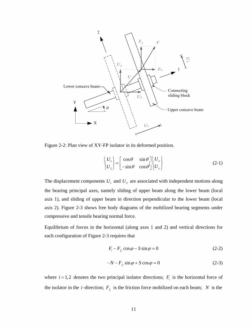
Figure 2-2: Plan view of XY-FP isolator in its deformed position.
1
2
cos sinsin cos
x
y
UUUU
θ θθ θ
⎧ ⎫⎧ ⎫ ⎡ ⎤=⎨ ⎬ ⎢ ⎥−⎣ ⎦⎩ ⎭ ⎩ ⎭
⎨ ⎬ (2-1)
The displacement components and are associated with independent motions along
the bearing principal axes, namely sliding of upper beam along the lower beam (local
axis 1), and sliding of upper beam in direction perpendicular to the lower beam (local
axis 2). Figure 2-3 shows free body diagrams of the mobilized bearing segments under
compressive and tensile bearing normal force.
1U 2U
Equilibrium of forces in the horizontal (along axes 1 and 2) and vertical directions for
each configuration of Figure 2-3 requires that
cos sin 0ii fF F Sϕ ϕ− − = (2-2)
sin cos 0if
N F Sϕ ϕ− − + = (2-3)
where denotes the two principal isolator directions; is the horizontal force of
the isolator in the -direction; is the friction force mobilized on each beam; is the
1, 2i = iF
iif
F N
11
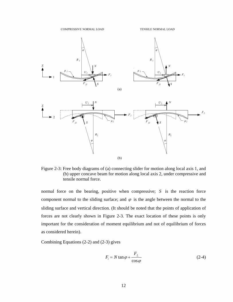
Figure 2-3: Free body diagrams of (a) connecting slider for motion along local axis 1, and (b) upper concave beam for motion along local axis 2, under compressive and tensile normal force.
normal force on the bearing, positive when compressive; is the reaction force
component normal to the sliding surface; and
S
ϕ is the angle between the normal to the
sliding surface and vertical direction. (It should be noted that the points of application of
forces are not clearly shown in Figure 2-3. The exact location of these points is only
important for the consideration of moment equilibrium and not of equilibrium of forces
as considered herein).
Combining Equations (2-2) and (2-3) gives
tancos
ifi
FF N ϕ
ϕ= + (2-4)
12
In view of the dependency of ϕ on the displacement component given by iU
sini iU R ϕ= (2-5)
Equation (2-4) can be written as
; 1, 2cos cos
ifi i
i
FNF U iR ϕ ϕ
= + = (2-6)
where iR is the radius of curvature of the circular trajectory of the pivot point of the
slider on top of each beam. This radius is equal to the radius of curvature of the surface of
each beam minus the small height of the pivot point to the surface. Equation (2-6)
describes the resisting force of the isolator along the i -direction in the general case of
large values of angle ϕ . It is synthesized by two components, one representing the
pendulum effect associated with a restoring force (in the case of compressive normal
load), and the other representing the contribution of friction developed at the sliding
interface.
Assuming small angles of rotation ϕ , Equation (2-6) reduces to the linearized form
; 1, 2ii i f
i
NF U F iR
= + = (2-7)
in which the friction forces associated with the two beams are
1 1 1 2 2 2
2
sgn( ) sgn( ) sgn( )f sideNF N U U N U UR
µ µ µ= + + 1 (2-8)
2 2 2 1 1 1
1
sgn( ) sgn( ) sgn( )f sideNF N U U N U UR
µ µ µ= + + 2 (2-9)
where 1µ and 2µ are the sliding friction coefficients of the lower and upper concave
beams, respectively; sideµ is the coefficient of friction associated with side contact
surface between the connecting block and the beams; and is the signum function
operating on the sliding velocities.
sgn( )
13

Equations (2-8) and (2-9) reveal the interaction between lateral forces and friction forces.
For instance, when the bearing upper beam moves with respect to the connecting block in
direction perpendicular to the lower beam (along axis 2), the developed shear force is
transferred onto one side of the lower beam. Thus, the side contact surface of the lower
beam is acted upon a normal force of magnitude
2F
2F , which results in increasing the
friction force on the lower beam, should motion along axis 1 occurs. Analogous
considerations can be made for the effect of lateral force on as dictated by
Equation (2-9).
1F2f
F
It should be noted that, the contribution of lateral forces and in friction forces
and , respectively, is small, on account of the fact that,
1F 2F2f
F
1fF side i Nµ µ is of higher order
and can be neglected, and ( )iN R Ui is less than 0.2 N , since FP bearings are typically
designed for displacement 0.2U R< . Therefore, the additional friction force is always
less than 0.2 side Nµ , with the maximum value attained only at the extreme displacement.
Supportive evidence of the small effect of lateral force interaction is provided graphically
in Figure 2-4 wherein simulated isolator force–displacement loops under bi-directional
motion are plotted against loops under uni-directional (along local axis 1) motion. In
particular, the imposed bi-directional motion in the upper graph of Figure 2-4 consists of
a linear displacement pattern in which 1 2 0 sinU U U tω= = , whereas the bi-directional
motion in the lower graph consists of an 8-shaped displacement pattern in which
1 0 sinU U tω= and 2 0 sin 2U U tω= , with 0 200U = mm and ω π= rad/sec. Identical
isolator interface conditions were assumed with sliding friction coefficient
1 2 0.05sideµ µ µ= = = and radius of curvature 990R = mm. It can be seen from these
plots that the error in the isolator force neglecting the effect of lateral force is only
about 5 percent.
1F 2F
Neglecting the effect of lateral force on friction force, as will be considered hereafter, the
forces needed to induce displacement [ ]1 2TU U U= on the bearing in the local co-
ordinate system are given collectively by
14

Displacement U1 (mm)
-200 -100 100 200-300 0 300
Isol
ator
For
ce F
1 / W
eigh
t
-0.2
-0.1
0.1
0.2
-0.3
0.0
0.3
U1=U0sinωt; U2=0
U1=U0sinωt; U2=U0sin2ωt
Imposed U1
Impo
sed
U2
Displacement U1 (mm)
-200 -100 100 200-300 0 300Is
olat
or F
orce
F1 /
Wei
ght
-0.2
-0.1
0.1
0.2
-0.3
0.0
0.3
U1=U0sinωt; U2=0
U1=U2=U0sinωt
Imposed U1
Impo
sed
U2
Figure 2-4: Effect of lateral force interaction in XY-FP isolator.
1 1 11
222 2 2
sgn( )0000 sgn( )
F U NN RNN RF U U
µµ
1U⎧ ⎫⎡ ⎤⎧ ⎫ ⎧ ⎫⎡ ⎤ ⎪ ⎪= +⎨ ⎬ ⎨ ⎬ ⎨ ⎬⎢ ⎥⎢ ⎥⎪ ⎪⎣ ⎦⎩ ⎭ ⎩ ⎭ ⎣ ⎦ ⎩ ⎭
(2-10)
The error involved in the linearization of Equation (2-6) is insignificant for all practical
purposes, since, as mentioned above, FP bearings are typically designed for displacement
, so that 0.2U < R cos 1ϕ ≈ .
In general, the normal force on the isolation bearing is a fast-varying function of time due
to the effect of vertical earthquake motion and the overturning moment effects. For a
vertically rigid superstructure, the normal force on the bearing at any given time is
synthesized by
1 gv OMu NN Wg W
⎛ ⎞= + +⎜
⎝ ⎠⎟ (2-11)
15
where is the weight acting on the isolator; W gvu is the vertical ground acceleration
(positive when the direction is upwards); and is the additional axial force due to
overturning moment effects (positive when compressive).
OMN
Evaluation of the bearing normal force according to Equation (2-11) is of utmost
importance for the accuracy of the XY-FP model. The fluctuation in the bearing axial
force caused by the vertical component of ground motion and overturning moments can
be large enough to cause reversal of the axial force from compression to tension.
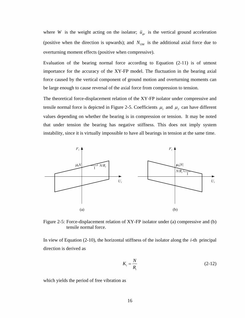
The theoretical force-displacement relation of the XY-FP isolator under compressive and
tensile normal force is depicted in Figure 2-5. Coefficients 1µ and 2µ can have different
values depending on whether the bearing is in compression or tension. It may be noted
that under tension the bearing has negative stiffness. This does not imply system
instability, since it is virtually impossible to have all bearings in tension at the same time.
Figure 2-5: Force-displacement relation of XY-FP isolator under (a) compressive and (b) tensile normal force.
In view of Equation (2-10), the horizontal stiffness of the isolator along the principal
direction is derived as
-thi
ii
NKR
= (2-12)
which yields the period of free vibration as
16
2( / )
ii
i
2 RWTW R g g
π= = π (2-13)
where denotes the two principal isolator directions and W is the weight acting on
the isolator. As in the conventional FP isolator, the period is independent of the supported
mass and dependent only on the geometry of the bearing.
1, 2i =
Having defined the constitutive relation of the bearing with respect to the local co-
ordinate system (Equation (2-10)), the corresponding force-displacement relationship in
the global co-ordinate system can be readily derived as
1
2
cos sinsin cos
Tx
y
F FF F
θ θθ θ
⎧ ⎫ ⎧ ⎫⎡ ⎤=⎨ ⎬ ⎢ ⎥−⎣ ⎦ ⎩ ⎭⎩ ⎭
⎨ ⎬ (2-14)
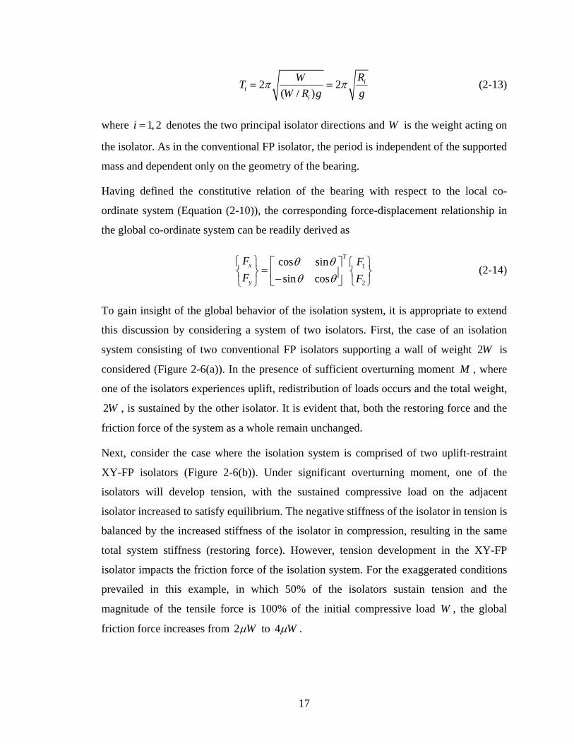
To gain insight of the global behavior of the isolation system, it is appropriate to extend
this discussion by considering a system of two isolators. First, the case of an isolation
system consisting of two conventional FP isolators supporting a wall of weight is
considered (Figure 2-6(a)). In the presence of sufficient overturning moment
2W
M , where
one of the isolators experiences uplift, redistribution of loads occurs and the total weight,
, is sustained by the other isolator. It is evident that, both the restoring force and the
friction force of the system as a whole remain unchanged.
2W
Next, consider the case where the isolation system is comprised of two uplift-restraint
XY-FP isolators (Figure 2-6(b)). Under significant overturning moment, one of the
isolators will develop tension, with the sustained compressive load on the adjacent
isolator increased to satisfy equilibrium. The negative stiffness of the isolator in tension is
balanced by the increased stiffness of the isolator in compression, resulting in the same
total system stiffness (restoring force). However, tension development in the XY-FP
isolator impacts the friction force of the isolation system. For the exaggerated conditions
prevailed in this example, in which 50% of the isolators sustain tension and the
magnitude of the tensile force is 100% of the initial compressive load W , the global
friction force increases from 2µW to 4µW .
17
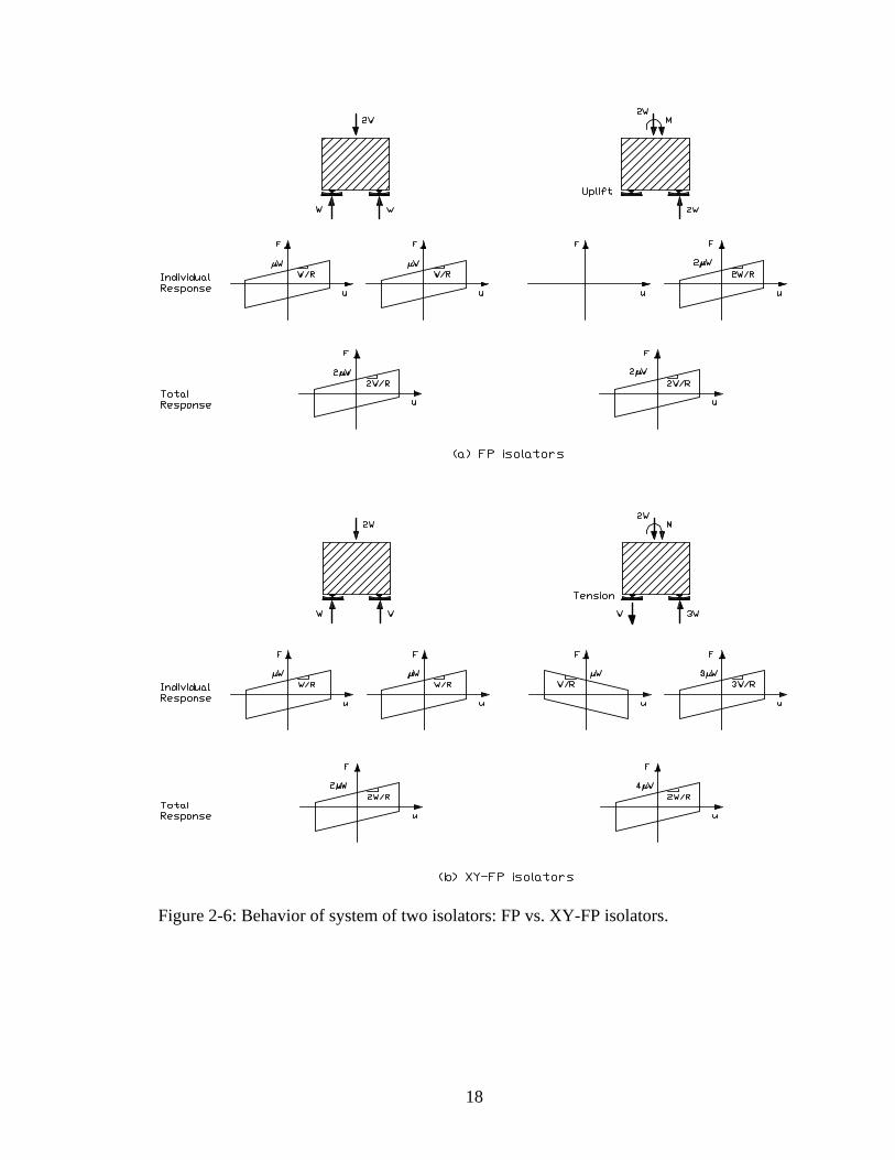
Figure 2-6: Behavior of system of two isolators: FP vs. XY-FP isolators.
18

SECTION 3
TESTING OF XY-FP ISOLATOR
3.1 Introduction
To gain a better understanding of the behavior and mechanical properties of the XY-FP
isolators, tests of a single isolator were conducted using the isolator testing machine in
the Structural Engineering and Earthquake Simulation Laboratory of the University at
Buffalo (Kasalanati and Constantinou, 1999).
3.2 Theoretical Background
Presented briefly herein, is the theoretical basis of certain aspects of frictional behavior
that are relevant to the interpretation of experimental results at the macroscopic level. A
detailed presentation of frictional aspects pertaining to sliding isolators can be found in
Constantinou et al. (1999).
The coefficient of sliding friction mobilized on a typical sliding bearing interface is
modeled by the following equation:
max max min( ) a us f f f eµ −= − − (3-1)
where minf and maxf are the minimum and maximum values of the coefficient of friction,
respectively, and is a parameter which controls the variation of the coefficient of
friction with velocity (Constantinou et al., 1990). The dependency of the coefficient of
friction on velocity is illustrated in Figure 3-1.
a
In general, parameters maxf , minf , and are functions of bearing pressure and
temperature. However, the dependency of
a
minf and on pressure is insignificant
(compared with that of
a
maxf ) and can be neglected (Tsopelas et al., 1994). A
representative expression describing the variation of parameter maxf with pressure is
given by
max max 0 max 0 max p( ) tanh( )f f f f pε= − − (3-2)
19
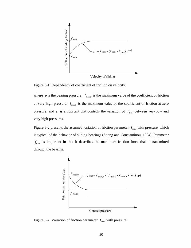
Figure 3-1: Dependency of coefficient of friction on velocity.
where p is the bearing pressure; max pf is the maximum value of the coefficient of friction
at very high pressure; max 0f is the maximum value of the coefficient of friction at zero
pressure; and ε is a constant that controls the variation of maxf between very low and
very high pressures.
Figure 3-2 presents the assumed variation of friction parameter maxf with pressure, which
is typical of the behavior of sliding bearings (Soong and Constantinou, 1994). Parameter
maxf is important in that it describes the maximum friction force that is transmitted
through the bearing.
Figure 3-2: Variation of friction parameter maxf with pressure.
20
3.3 Testing Machine Description
The apparatus shown in Figure 3-3 is comprised of the following components: (a) two
horizontal beams – a lower support beam fixed to the rigid floor and an upper loading
beam driven by a horizontal actuator; (b) three actuators – one horizontal actuator to
impose the lateral displacement and two vertical actuators to both support the loading
beam and maintain the axial load on the bearing; and (c) three load cells monitoring the
load on the bearing – one reaction load cell (placed directly under the bearing) that
measures directly both the axial and shear forces experienced by the bearing, and a load
cell connected to each of the vertical actuators to control the vertical load.
The control strategy for these bearing tests consisted of maintaining the prescribed axial
load on the bearing while imposing the desired lateral displacement. A detailed
description and principles of operation of the testing machine can be found in Kasalanati
and Constantinou (1999).
Figure 3-3: Schematic of isolator testing apparatus.
3.4 Testing Program
The isolator testing program involved a series of laboratory tests conducted on a single
XY-FP isolator on the aforementioned apparatus (Figure 3-4). The isolator used in these
tests was manufactured by Earthquake Protection Systems in Vallejo, California, with the
dimensions shown in Figure 3-5. It was constructed of stainless steel and was designed to
21

have a displacement capacity of 203 mm (8 in). The radius of curvature of each concave
beam is 990 mm (39 in.). Views of XY-FP isolator during testing in 0°, 45°, and 90°
orientation are presented in Figure 3-6.
Figure 3-4: Photograph of isolator testing apparatus.
Figure 3-5: Two-dimensional view of the uplift-restraint XY-FP isolator used in this study.
The conditions pertaining to the displacement-controlled testing included a range of
isolator orientation angles, normal loads (compressive and tensile), and peak sliding
velocities. Table 3-1 presents the values of the variables used in the isolator testing
program.
22

Figure 3-6: Views of XY-FP isolator during testing in 0°, 45°, and 90° orientation.
Table 3-1: Values of parameters used in isolator testing program.
Isolator Orientation 0°, 45°, 90°
Normal Load (kN) 27, 54, 108 : compression 27 : tension
Displacement Amplitude, (mm) 0u 100
Frequency, f (Hz) 0.01, 0.1, 0.3, 0.6, 0.8
Velocity Amplitude, 0 2v 0fuπ= (mm/s) 6.3, 63, 188, 377, 503
The imposed displacement history is illustrated in Figure 3-7. The test started with an idle
time of 10 sec fronted by a built-up segment of 60 sec in which a displacement amplitude
is reached under very low sliding velocity. During this build-up time, truly quasi-static
conditions are present permitting measurements of the breakaway (or static) coefficient
0u
Time
Dis
plac
emen
t
Idletimetb = 10 s
Idletime
Build-up timeta = 60 s
0 cos[2 ( )]a bu u f t t tπ= − −
20 ( / )au u t t=
Figure 3-7: Imposed displacement history for XY-FP isolator testing.
23
of friction at initiation of motion and of the sliding coefficient of friction at very low
velocity (parameter minf ). Subsequently, it is followed by an idle time of 10 sec and
three-and-a-quarter cycles of harmonic displacement history as indicated in Figure 3-7.
3.5 Test Results
To expand our understanding of the behavior of the new XY-FP isolator, frictional force-
displacement loops are plotted for different values of bearing pressure, peak sliding
velocity, and bearing orientations. The recorded shear force was used to extract various
frictional characteristics of interest. The frictional force during sliding in the “build-up
time” interval upon division by the normal force results in the sliding friction coefficient
at very low velocity, minf . The value of the coefficient of friction at peak velocity (zero
displacement), occurring at the first cycle, is practically the maximum sliding coefficient
of friction, maxf . Information on the breakaway (or static) friction was not extracted since
special specimen preparation was needed (see Constantinou et al., 1999 for details). In
general, the breakaway coefficient of friction value is less than maxf for the tested
conditions of normal temperature.
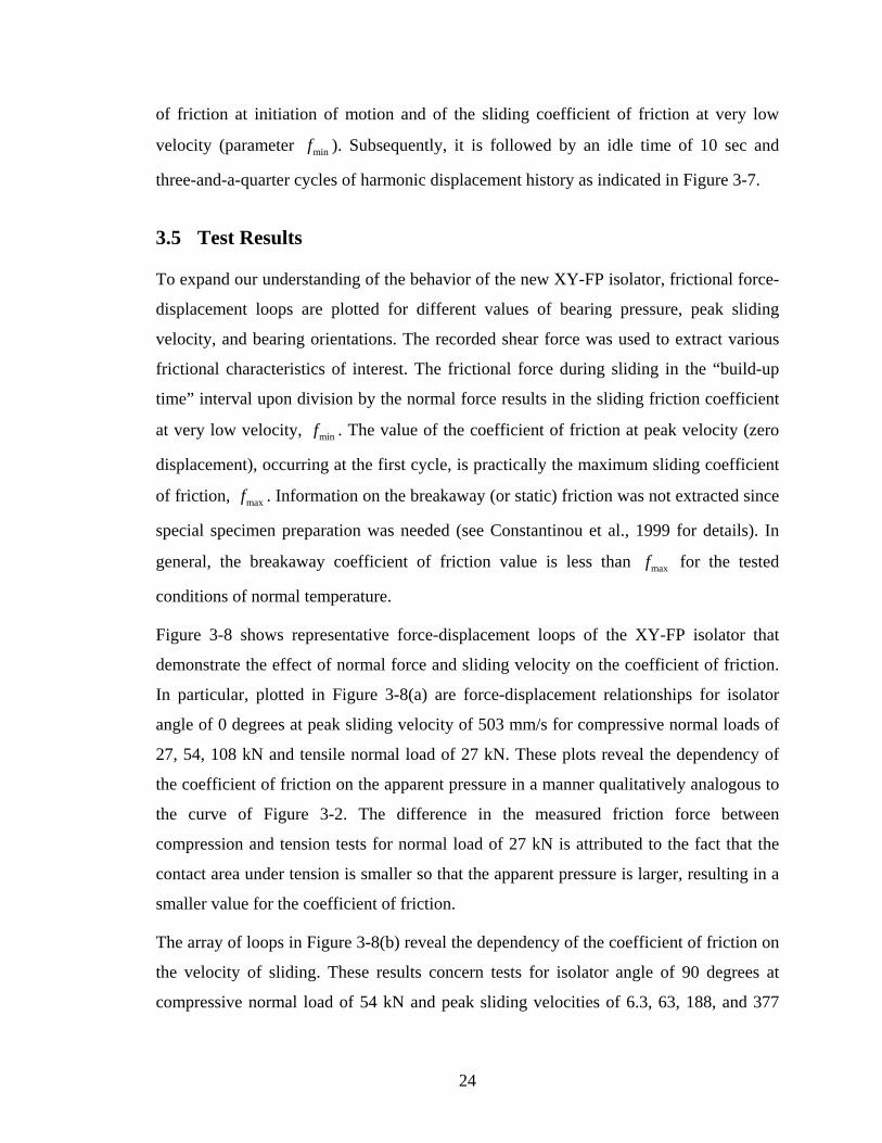
Figure 3-8 shows representative force-displacement loops of the XY-FP isolator that
demonstrate the effect of normal force and sliding velocity on the coefficient of friction.
In particular, plotted in Figure 3-8(a) are force-displacement relationships for isolator
angle of 0 degrees at peak sliding velocity of 503 mm/s for compressive normal loads of
27, 54, 108 kN and tensile normal load of 27 kN. These plots reveal the dependency of
the coefficient of friction on the apparent pressure in a manner qualitatively analogous to
the curve of Figure 3-2. The difference in the measured friction force between
compression and tension tests for normal load of 27 kN is attributed to the fact that the
contact area under tension is smaller so that the apparent pressure is larger, resulting in a
smaller value for the coefficient of friction.
The array of loops in Figure 3-8(b) reveal the dependency of the coefficient of friction on
the velocity of sliding. These results concern tests for isolator angle of 90 degrees at
compressive normal load of 54 kN and peak sliding velocities of 6.3, 63, 188, and 377
24
-100 -50 50 100-150 0 150
Shea
r For
ce /
Nor
mal
For
ce
-0.3-0.2-0.1
0.10.20.3
-0.4
0.0
0.4
Compressive Normal Load = 27 kN
-100 -50 50 100-150 0 150
Shea
r For
ce /
Nor
mal
For
ce
-0.3-0.2-0.1
0.10.20.3
-0.4
0.0
0.4
Displacement (mm)
-100 -50 50 100-150 0 150
Shea
r For
ce /
Nor
mal
For
ce
-0.3-0.2-0.1
0.10.20.3
-0.4
0.0
0.4
Tensile Normal Load = 27 kN
-100 -50 50 100-150 0 150
Shea
r For
ce /
Nor
mal
For
ce
-0.3-0.2-0.1
0.10.20.3
-0.4
0.0
0.4
Peak Velocity = 503 mm/sIsolator Angle = 0º
Compressive Normal Load = 54 kN
Compressive Normal Load = 108 kN
-100 -50 50 100-150 0 150
-0.3-0.2-0.1
0.10.20.3
-0.4
0.0
0.4
-100 -50 50 100-150 0 150
-0.3-0.2-0.1
0.10.20.3
-0.4
0.0
0.4
Displacement (mm)
-100 -50 50 100-150 0 150
-0.3-0.2-0.1
0.10.20.3
-0.4
0.0
0.4
-100 -50 50 100-150 0 150
-0.3-0.2-0.1
0.10.20.3
-0.4
0.0
0.4
Peak Velocity = 6.3 mm/s
Peak Velocity = 63 mm/s
Peak Velocity = 188 mm/s
Peak Velocity = 377 mm/s
Compressive Normal Load = 54 kNIsolator Angle = 90º
(a) (b)
Figure 3-8: Recorded normalized force-displacement loops of XY-FP isolator demonstrating the effect of (a) normal force, and (b) sliding velocity.
25

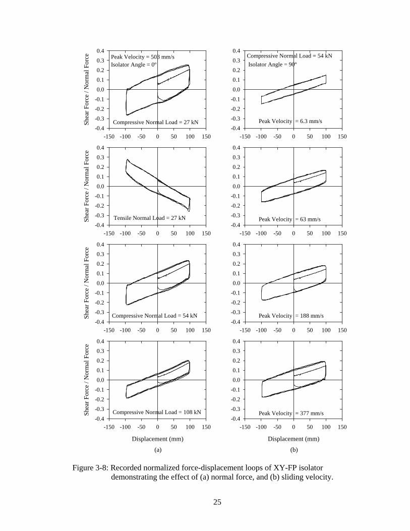
mm/s. Collectively, the dependency of the coefficient of friction on the sliding velocity
for each of the two component bearing beams is depicted in Figure 3-9. Superposed to the
experimental results, are theoretical predictions of Equation (3-1) upon calibration with
appropriate selection of parameters. Values of the parameters are presented in Table 3-2.
Evidently, Equation (3-1) describes well the observed dependency of the sliding
coefficient of friction on velocity.
Table 3-2: Parameters used in calibration of the equation describing the dependency of coefficient of friction on velocity (Equation (3-1)).
Lower Bearing Beam Upper Bearing Beam
Normal Load (kN) Normal Load (kN) Compressive Tensile Compressive Tensile
Parameters in Equation (3-1)
27 54 108 27 27 54 108 27
minf 0.061 0.044 0.032 0.058 0.046 0.045 0.026 0.070
maxf 0.142 0.110 0.070 0.079 0.137 0.106 0.066 0.083
α (s/m) 112 61.9 67.2 48.9 11.3 14.7 14.8 62.0
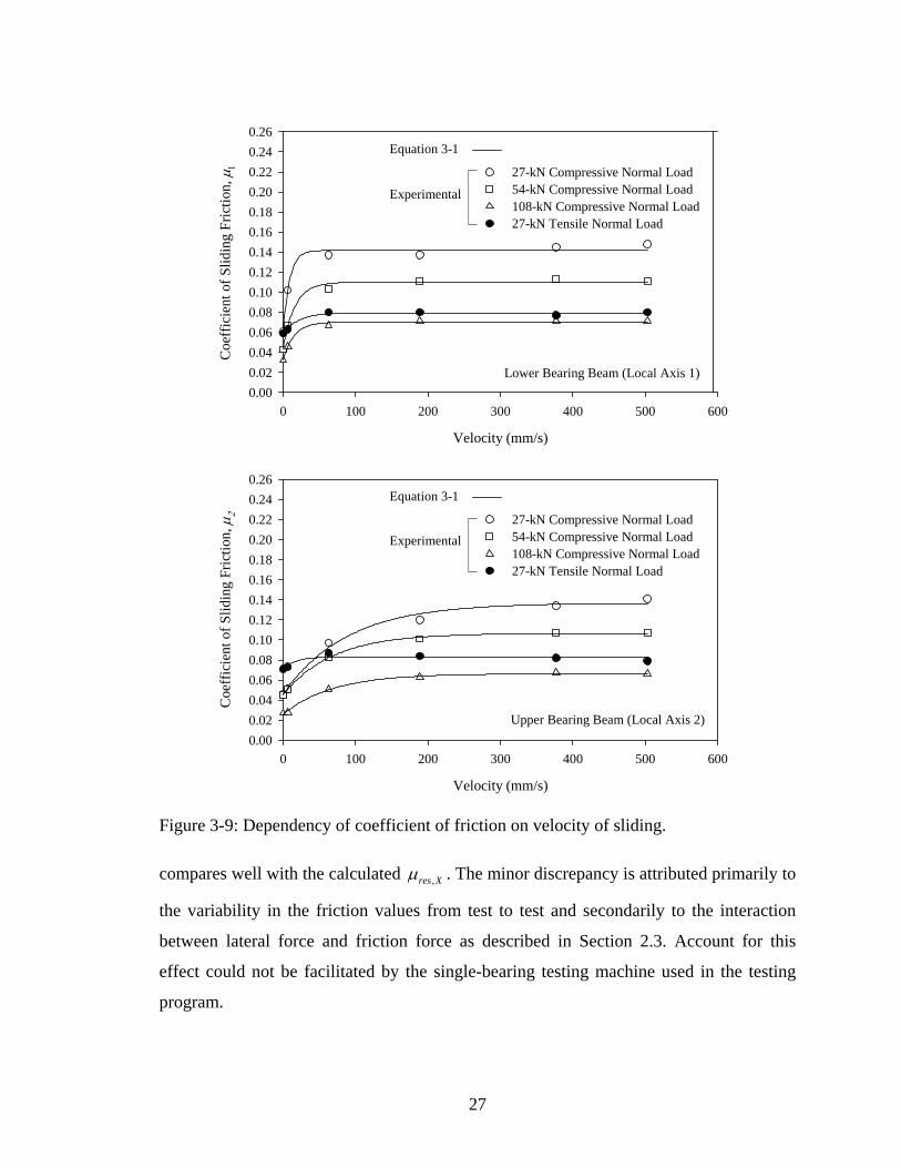
Figure 3-10 presents recorded normalized force-displacement loops for compressive and
tensile normal loads and for isolator orientations of 0, 90, and 45 degrees. Results are
plotted for the highest values of normal load and sliding velocity of Table 3-1, since more
uncertainties in the frictional characteristics of the isolators and in the measurement
system are to be expected under low velocity and pressure. These plots serve to verify
that the equivalent friction force in any given direction can be approximated by the
friction forces acting along the isolator principal axes 1 and 2 as the projection of their
vectorial sum onto the direction of interest. With reference to Figure 3-10(a), the
normalized friction force along the testing (global X) direction, from the 45-degree test
for compressive normal load of 108 kN and sliding velocity of 503 mm/s is 0.087Xµ = .
Under the same values of testing parameters, the normalized friction forces from testing
in 0- and 90-degree orientations are 1 0.063µ = and 2 0.056µ = , respectively. The
vectorial sum of and 1µ 2µ gives a resultant of 0.084resµ = with practically the same
projection onto the X direction, , 0.084res Xµ = . Evidently, the recorded value of Xµ
26
Lower Bearing Beam (Local Axis 1)
Velocity (mm/s)
0 100 200 300 400 500 600
Coe
ffic
ient
of S
lidin
g Fr
ictio
n, µ
1
0.000.020.040.060.080.100.120.140.160.180.200.220.240.26
Upper Bearing Beam (Local Axis 2)
Velocity (mm/s)
0 100 200 300 400 500 600
Coe
ffic
ient
of S
lidin
g Fr
ictio
n, µ
2
0.000.020.040.060.080.100.120.140.160.180.200.220.240.26
27-kN Compressive Normal Load 54-kN Compressive Normal Load 108-kN Compressive Normal Load 27-kN Tensile Normal Load
Experimental
Equation 3-1
27-kN Compressive Normal Load 54-kN Compressive Normal Load 108-kN Compressive Normal Load 27-kN Tensile Normal Load
Experimental
Equation 3-1
Figure 3-9: Dependency of coefficient of friction on velocity of sliding.
compares well with the calculated ,res Xµ . The minor discrepancy is attributed primarily to
the variability in the friction values from test to test and secondarily to the interaction
between lateral force and friction force as described in Section 2.3. Account for this
effect could not be facilitated by the single-bearing testing machine used in the testing
program.
27

-100 -50 50 100-150 0 150
Shea
r For
ce /
Nor
mal
For
ce
-0.3
-0.2
-0.1
0.1
0.2
0.3
-0.4
0.0
0.4
Compressive Normal Load
Isolator Angle =0º
Tensile Normal Load
Peak Velocity = 503 mm/sNormal Load = 108 kN
-100 -50 50 100-150 0 150
Shea
r For
ce /
Nor
mal
For
ce
-0.3
-0.2
-0.1
0.1
0.2
0.3
-0.4
0.0
0.4
Isolator Angle =90º
-100 -50 50 100-150 0 150
-0.3
-0.2
-0.1
0.1
0.2
0.3
-0.4
0.0
0.4
Isolator Angle =0º
Peak Velocity = 503 mm/sNormal Load = 27 kN
-100 -50 50 100-150 0 150
-0.3
-0.2
-0.1
0.1
0.2
0.3
-0.4
0.0
0.4
Isolator Angle =90º
Displacement (mm)
-100 -50 50 100-150 0 150
Shea
r For
ce /
Nor
mal
For
ce
-0.3
-0.2
-0.1
0.1
0.2
0.3
-0.4
0.0
0.4
Isolator Angle =45º
Displacement (mm)
-100 -50 50 100-150 0 150
-0.3
-0.2
-0.1
0.1
0.2
0.3
-0.4
0.0
0.4
Isolator Angle =45º
(a) (b)
Figure 3-10: Recorded normalized force-displacement loops of XY-FP isolator for different isolator orientations for (a) compressive and (b) tensile normal load.
28
It can be argued that the comparison above involved friction forces based on
incompatible velocities. Namely, all tests of Figure 3-10(a) were contacted under the
same peak sliding velocity (503 mm/s) disregarding the fact that during the 45-degree test
the velocity components along the isolator principal axes were smaller. This, clearly, is
crossed out by considering high sliding velocity wherein friction becomes practically
constant, as dictated by Equation (3-1).
One may observe in Figure 3-10 that the slopes of the normalized force-displacement
loops, say in the portion corresponding to the built-up of displacement amplitude wherein
velocity effects are not present to cause any distortion, are slightly different for isolator
orientations of 0 and 90 degrees. The slopes (stiffnesses), theoretically given by 1/ iR ,
were expected to be equal in view of identical radii of curvature of the two concave
bearing beams confirmed through measurement and verified via analogous loops from
shake-table testing (see Section 5). The discrepancy may be attributed to the fact that in
the 0-degree configuration (see Figure 3-6) the P − ∆ moment is transferred directly on
the load cell, while in the 90-degree configuration the moment is transferred above. This
resulted in a difference in the state of stress in the load cell between the two
configurations, which was reflected in the measurements due to channel cross-talk. The
error in the measurements could not be corrected because of the nonlinear nature of the
interaction between the electronic circuits in the load cells measuring axial force, shear
force, and bending moment.
29


SECTION 4
MODEL FOR EARTHQUAKE SIMULATOR TESTING
4.1 Introduction
The testing program on the earthquake simulator at the University at Buffalo involved a
five-story base-isolated model structure. The superstructure consisted of a steel frame
used in previous testing of energy dissipation systems at the University at Buffalo (e.g.,
Chang et al., 1993). The properties and dynamic characteristics of the model excluding
the isolation system and fixed at the base were identified and are presented in Section 4.6.
The isolation system, comprised of four XY-FP isolators, was installed beneath a base
and rotated for testing in different directions. Specifically, tests were done at 0-degree,
45-degree, and 90-degree angle of lower bearing beam with respect to the direction of
horizontal excitation. The testing program utilized a number of recorded ground motions
with a wide range of both frequency content and amplitude.
4.2 Model Description
Figures 4-1 and 4-2 show a photograph and a schematic of the model, respectively. At a
quarter length scale, the single-bay moment-resisting steel frame is square in plan with a
dimension of 1.321 m. The story heights are 1.092 m for the first story and 1.194 m for
the other stories, for a total height of 5.868 m. The member layout is identical for all
stories. The floors are comprised of MC6x12 channel sections. The cross sections of
columns, beams, channels, and bracing are shown in Figure 4-3.
The model scale was chosen to be 4. In conforming to the similitude law, artificial mass,
in the form of steel plates and lead blocks, was added to the structure at all floor levels.
Table 4-1 presents the relevant scale factors associated with testing. The structure was
attached to a rigid base under which the isolation system was installed. The distribution
of mass is effectively 13.75 kN (3.1 kip) per floor and 37.8 kN (8.5 kip) for the base, for
a total weight of 106.5 kN (24 kip). Installed beneath the rigid base, the isolation system
consisted of four identical uplift-prevention XY-FP isolators. The isolator dimensions are
shown in Figure 3-5.
31
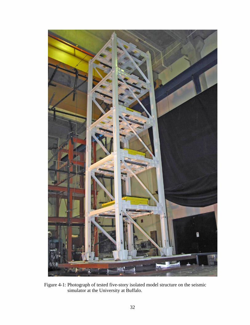
Figure 4-1: Photograph of tested five-story isolated model structure on the seismic simulator at the University at Buffalo.
32
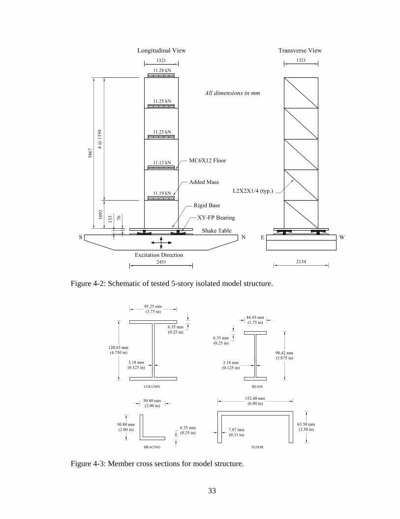
Figure 4-2: Schematic of tested 5-story isolated model structure.
Figure 4-3: Member cross sections for model structure.
33

Table 4-1: Scale factors for model structure.
Quantity Dimension Scale Factor
Linear Dimension L 4 Displacement L 4
Time T 2
Velocity LT-1 2
Acceleration LT-2 1
Frequency T-1 1/2
Stress / Pressure ML-1T-2 1
Force MLT-2 16
Strain - 1
4.3 Pushover Analysis
A pushover analysis of the model structure fixed at the base and exclusive of the isolation
system was performed for the strong (N-S) direction of the model to identify its collapse
mechanism and calculate the base shear strength. The base shear strength of the frame
was also established using the method presented in Ramirez et al., 2001 (see Appendix
A). These results are confirmed by pushover analysis using the program SAP2000
(Computers and Structures, 1998). The analysis determined that the model exhibits
proper behavior with plastic hinges developing in the beams and that the base shear
strength of the model is approximately equal to its weight.
4.4 Instrumentation
The instrumentation of the five-story model structure consisted of accelerometers and
displacement transducers which recorded the horizontal accelerations and displacements
of the frame at floor levels, the rigid base, and the shake table. In addition, the first-story
columns were instrumented with strain gauged load cells to measure the first-story shear
force. Figure 4-4 depicts the instrumentation scheme employed in the testing program. A
list of monitored channels and their corresponding descriptions are given in Table 4-2.
As depicted in Figure 4-4 accelerations were recorded on the east and west side at each
34
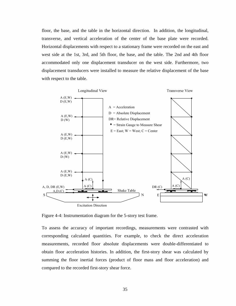
floor, the base, and the table in the horizontal direction. In addition, the longitudinal,
transverse, and vertical acceleration of the center of the base plate were recorded.
Horizontal displacements with respect to a stationary frame were recorded on the east and
west side at the 1st, 3rd, and 5th floor, the base, and the table. The 2nd and 4th floor
accommodated only one displacement transducer on the west side. Furthermore, two
displacement transducers were installed to measure the relative displacement of the base
with respect to the table.
Figure 4-4: Instrumentation diagram for the 5-story test frame.
To assess the accuracy of important recordings, measurements were contrasted with
corresponding calculated quantities. For example, to check the direct acceleration
measurements, recorded floor absolute displacements were double-differentiated to
obtain floor acceleration histories. In addition, the first-story shear was calculated by
summing the floor inertial forces (product of floor mass and floor acceleration) and
compared to the recorded first-story shear force.
35
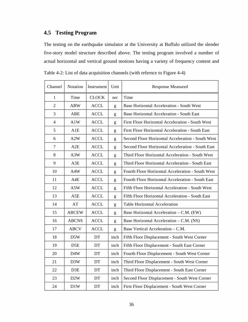
4.5 Testing Program
The testing on the earthquake simulator at the University at Buffalo utilized the slender
five-story model structure described above. The testing program involved a number of
actual horizontal and vertical ground motions having a variety of frequency content and
Table 4-2: List of data acquisition channels (with refernce to Figure 4-4)
Channel Notation Instrument Unit Response Measured
1 Time CLOCK sec Time
2 ABW ACCL g Base Horizontal Acceleration - South West
3 ABE ACCL g Base Horizontal Acceleration - South East
4 A1W ACCL g First Floor Horizontal Acceleration - South West
5 A1E ACCL g First Floor Horizontal Acceleration - South East
6 A2W ACCL g Second Floor Horizontal Acceleration - South West
7 A2E ACCL g Second Floor Horizontal Acceleration - South East
8 A3W ACCL g Third Floor Horizontal Acceleration - South West
9 A3E ACCL g Third Floor Horizontal Acceleration - South East
10 A4W ACCL g Fourth Floor Horizontal Acceleration - South West
11 A4E ACCL g Fourth Floor Horizontal Acceleration - South East
12 A5W ACCL g Fifth Floor Horizontal Acceleration - South West
13 A5E ACCL g Fifth Floor Horizontal Acceleration - South East
14 AT ACCL g Table Horizontal Acceleration
15 ABCEW ACCL g Base Horizontal Acceleration – C.M. (EW)
16 ABCNS ACCL g Base Horizontal Acceleration – C.M. (NS)
17 ABCV ACCL g Base Vertical Acceleration – C.M.
18 D5W DT inch Fifth Floor Displacement - South West Corner
19 D5E DT inch Fifth Floor Displacement - South East Corner
20 D4W DT inch Fourth Floor Displacement - South West Corner
21 D3W DT inch Third Floor Displacement - South West Corner
22 D3E DT inch Third Floor Displacement - South East Corner
23 D2W DT inch Second Floor Displacement - South West Corner
24 D1W DT inch First Floor Displacement - South West Corner
36

Table 4-2: List of data acquisition channels (cont.)
Channel Notation Instrument Unit Response Measured
25 D1E DT inch First Floor Displacement - South East Corner
26 DRBW DT inch Base Relative Displacement - South West
27 DRBE DT inch Base Relative Displacement - South East
28 DBW DT inch Base Displacement - South West
29 DBE DT inch Base Displacement - South East
30 DBEW DT inch Transverse Base Displacement - East
31 ALAT ACCL g Table Horizontal Acceleration
32 SHEAR LOAD CELL kips First Story Shear Force
34 DTH DT inch Table Horizontal Displacement – South Center
amplitude. Table 4-3 lists the earthquake motions used for the simulator testing together
with their peak ground motion characteristics at the prototype (full) scale. Each record
was compressed in time by a factor of two to conform to the similitude requirements of
Table 4-1.
Figures 4-5 through 4-13 present the recorded histories of the table motion in nine tests
with these earthquake inputs. The acceleration and displacement records were measured
directly, whereas the velocity record was calculated by differentiating the displacement
record. Each of these figures presents the 5-percent damped response spectrum (in
prototype scale) of the table motion, and the spectrum of the target history. It can be
observed that the shake table reproduced motions that are in acceptable agreement with
the target motions in the period range of the isolated model structure.
The isolation system was rotated below the base plate for testing in different directions.
Specifically, tests were undertaken at 0-degree, 45-degree, and 90-degree angle of the
lower bearing beam with respect to the direction of horizontal excitation. A complete list
of tests conducted is presented in Table 4-4. In this table, V denotes the vertical
earthquake component.
37

Table 4-3: List of earthquake motions and their characteristics in prototype scale.
Peak Ground Motion Notation Excitation Component
Disp. (mm)
Vel. (mm/s)
Accel.(g)
El Centro S00E Imperial Valley, 1940 S00E 109 335 0.34
El Centro V Imperial Valley, 1940 Vertical 92 107 0.21
Taft N21E Kern County, 1952 N21E 67 157 0.16
Taft V Kern County, 1952 Vertical 45 66 0.11
Newhall 90º Northridge-Newhall, LA County Fire Station, 1994 90º 176 748 0.58
Newhall 360º Northridge-Newhall, LA County Fire Station, 1994 360º 305 947 0.59
Newhall V Northridge-Newhall, LA County Fire Station, 1994 Vertical 163 315 0.55
Sylmar 90º Northridge-Sylmar, Parking Lot, 1994 90º 152 769 0.60
Sylmar V Northridge-Sylmar, Parking Lot, 1994 Vertical 85 191 0.54
Kobe N-S Kobe Station, Japan, 1995 N-S 207 914 0.83
Kobe V Kobe Station, Japan, 1995 Vertical 103 383 0.34
Pacoima S74W San Fernando, Pacoima Dam, 1971 S74W 108 568 1.08
Pacoima S16E San Fernando, Pacoima Dam, 1971 S16E 365 1132 1.17
Pacoima V San Fernando, Pacoima Dam, 1971 Vertical 182 565 0.71
Hachinohe N-S Tokachi, Hachinohe, Japan, 1968 N-S 119 357 0.23
38
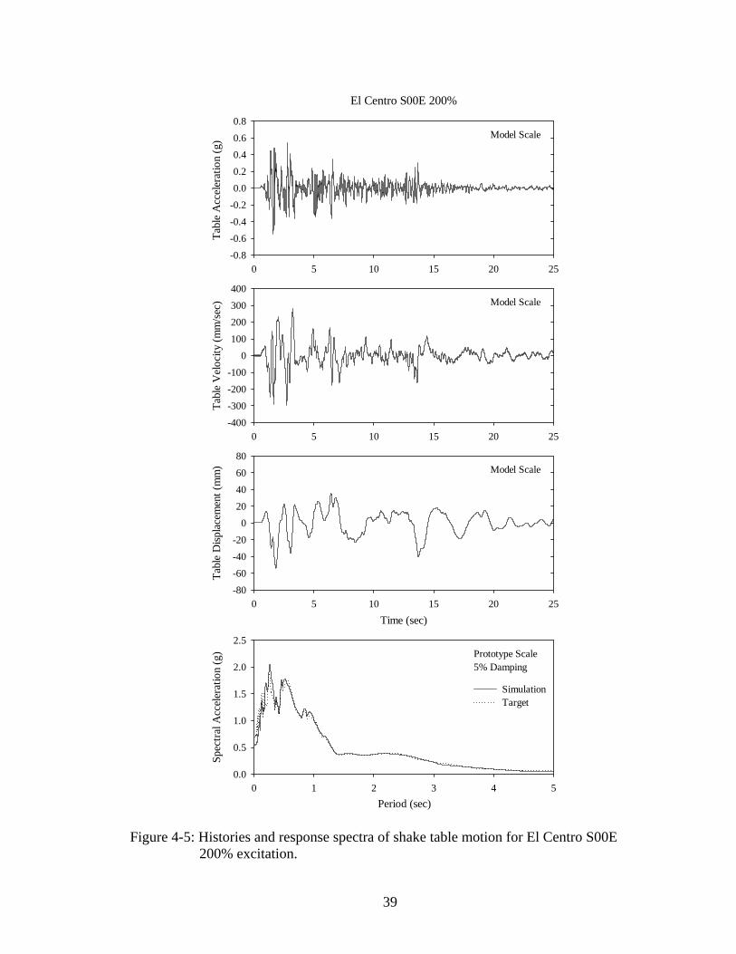
0 5 10 15 20 25
Tabl
e V
eloc
ity (m
m/s
ec)
-400-300-200-100
0100200300400
0 5 10 15 20 25
Tabl
e A
ccel
erat
ion
(g)
-0.8-0.6-0.4-0.20.00.20.40.60.8
Time (sec)0 5 10 15 20 25
Tabl
e D
ispla
cem
ent (
mm
)
-80-60-40-20
020406080
Period (sec)0 1 2 3 4 5
Spec
tral A
ccel
erat
ion
(g)
0.0
0.5
1.0
1.5
2.0
2.5
SimulationTarget
El Centro S00E 200%
Prototype Scale5% Damping
Model Scale
Model Scale
Model Scale
Figure 4-5: Histories and response spectra of shake table motion for El Centro S00E 200% excitation.
39
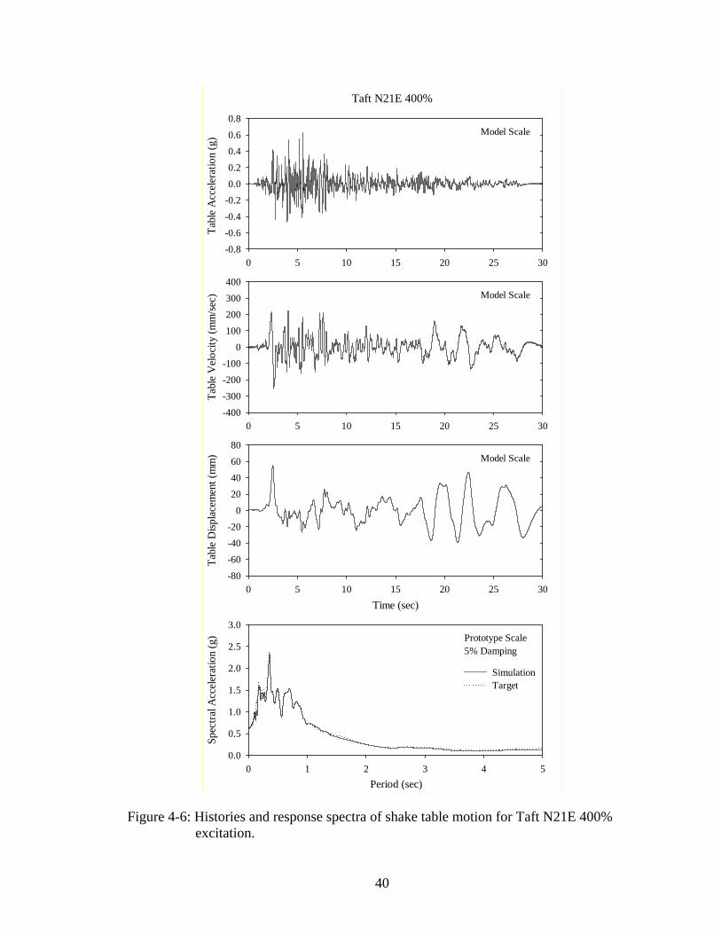
0 5 10 15 20 25 30
Tabl
e V
eloc
ity (m
m/s
ec)
-400-300-200-100
0100200300400
0 5 10 15 20 25 30
Tabl
e A
ccel
erat
ion
(g)
-0.8-0.6-0.4-0.20.00.20.40.60.8
Time (sec)0 5 10 15 20 25 30
Tabl
e D
ispla
cem
ent (
mm
)
-80-60-40-20
020406080
Period (sec)0 1 2 3 4 5
Spec
tral A
ccel
erat
ion
(g)
0.0
0.5
1.0
1.5
2.0
2.5
3.0
SimulationTarget
Taft N21E 400%
Prototype Scale5% Damping
Model Scale
Model Scale
Model Scale
Figure 4-6: Histories and response spectra of shake table motion for Taft N21E 400% excitation.
40

0 5 10 15
Tabl
e V
eloc
ity (m
m/s
ec)
-400-300-200-100
0100200300400
0 5 10 15
Tabl
e A
ccel
erat
ion
(g)
-0.8-0.6-0.4-0.20.00.20.40.60.8
Time (sec)0 5 10 15
Tabl
e D
ispla
cem
ent (
mm
)
-60
-40
-20
0
20
40
60
Period (sec)0 1 2 3 4 5
Spec
tral A
ccel
erat
ion
(g)
0.0
0.5
1.0
1.5
2.0
2.5
3.0
SimulationTarget
Newhall 90 100%
Prototype Scale5% Damping
Model Scale
Model Scale
Model Scale
Figure 4-7: Histories and response spectra of shake table motion for Newhall 90 100% excitation.
41
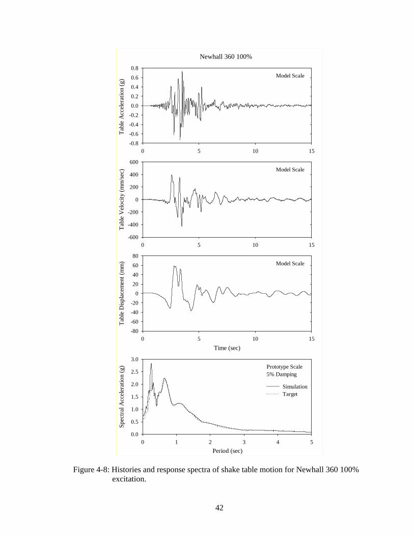
0 5 10 15
Tabl
e V
eloc
ity (m
m/s
ec)
-600
-400
-200
0
200
400
600
0 5 10 15
Tabl
e A
ccel
erat
ion
(g)
-0.8-0.6-0.4-0.20.00.20.40.60.8
Time (sec)0 5 10 15
Tabl
e D
ispla
cem
ent (
mm
)
-80-60-40-20
020406080
Period (sec)0 1 2 3 4 5
Spec
tral A
ccel
erat
ion
(g)
0.0
0.5
1.0
1.5
2.0
2.5
3.0
SimulationTarget
Newhall 360 100%
Prototype Scale5% Damping
Model Scale
Model Scale
Model Scale
Figure 4-8: Histories and response spectra of shake table motion for Newhall 360 100% excitation.
42

0 5 10 15
Tabl
e V
eloc
ity (m
m/s
ec)
-400-300-200-100
0100200300400
0 5 10 15
Tabl
e A
ccel
erat
ion
(g)
-0.8-0.6-0.4-0.20.00.20.40.60.8
Time (sec)0 5 10 15
Tabl
e D
ispla
cem
ent (
mm
)
-60
-40
-20
0
20
40
60
Period (sec)0 1 2 3 4 5
Spec
tral A
ccel
erat
ion
(g)
0.0
0.5
1.0
1.5
SimulationTarget
Sylmar 90 100%
Prototype Scale5% Damping
Model Scale
Model Scale
Model Scale
Figure 4-9: Histories and response spectra of shake table motion for Sylmar 90 100% excitation.
43

0 5 10 15
Tabl
e V
eloc
ity (m
m/s
ec)
-600
-400
-200
0
200
400
600
0 5 10 15
Tabl
e A
ccel
erat
ion
(g)
-0.8-0.6-0.4-0.20.00.20.40.60.8
Time (sec)0 5 10 15
Tabl
e D
ispla
cem
ent (
mm
)
-60
-40
-20
0
20
40
60
Period (sec)0 1 2 3 4 5
Spec
tral A
ccel
erat
ion
(g)
0.0
0.5
1.0
1.5
2.0
2.5
3.0
SimulationTarget
Kobe N-S 100%
Prototype Scale5% Damping
Model Scale
Model Scale
Model Scale
Figure 4-10: Histories and response spectra of shake table motion for Kobe N-S 100% excitation.
44

0 2 4 6 8 10
Tabl
e V
eloc
ity (m
m/s
ec)
-400-300-200-100
0100200300400
0 2 4 6 8 10
Tabl
e A
ccel
erat
ion
(g)
-0.8-0.6-0.4-0.20.00.20.40.60.8
Time (sec)0 2 4 6 8 10
Tabl
e D
ispla
cem
ent (
mm
)
-40
-20
0
20
40
Period (sec)0 1 2 3 4 5
Spec
tral A
ccel
erat
ion
(g)
0.0
0.5
1.0
1.5
2.0
2.5
3.0
SimulationTarget
Pacoima S74W 100%
Prototype Scale5% Damping
Model Scale
Model Scale
Model Scale
Figure 4-11: Histories and response spectra of shake table motion for Pacoima S74W 100% excitation.
45

0 2 4 6 8 10
Tabl
e V
eloc
ity (m
m/s
ec)
-600
-400
-200
0
200
400
600
0 2 4 6 8 10
Tabl
e A
ccel
erat
ion
(g)
-1.2
-0.8
-0.4
0.0
0.4
0.8
1.2
Time (sec)0 2 4 6 8 10
Tabl
e D
ispla
cem
ent (
mm
)
-120
-80
-40
0
40
80
120
Period (sec)0 1 2 3 4 5
Spec
tral A
ccel
erat
ion
(g)
0.0
0.5
1.0
1.5
2.0
2.5
3.0
3.5
SimulationTarget
Pacoima S16E 100%
Prototype Scale5% Damping
Model Scale
Model Scale
Model Scale
Figure 4-12: Histories and response spectra of shake table motion for Pacoima S16E 100% excitation.
46
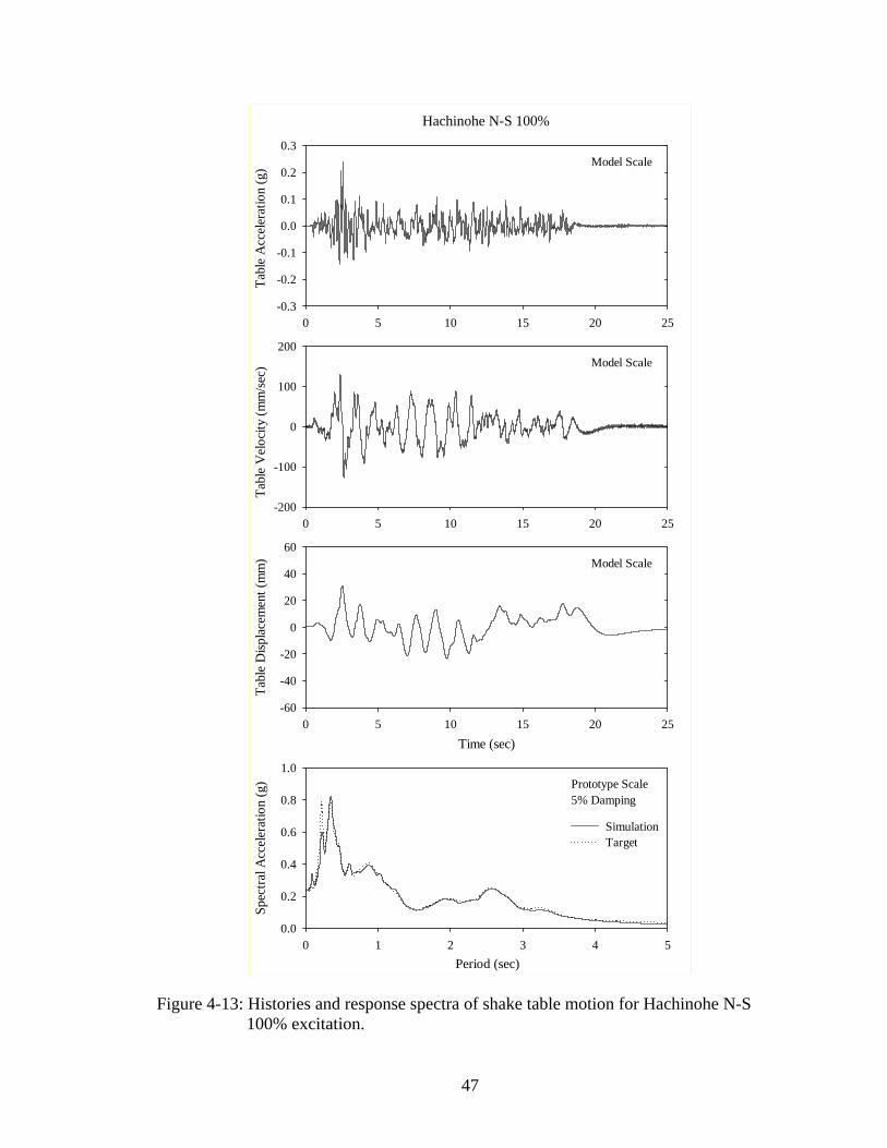
0 5 10 15 20 25
Tabl
e V
eloc
ity (m
m/s
ec)
-200
-100
0
100
200
0 5 10 15 20 25
Tabl
e A
ccel
erat
ion
(g)
-0.3
-0.2
-0.1
0.0
0.1
0.2
0.3
Time (sec)0 5 10 15 20 25
Tabl
e D
ispla
cem
ent (
mm
)
-60
-40
-20
0
20
40
60
Period (sec)0 1 2 3 4 5
Spec
tral A
ccel
erat
ion
(g)
0.0
0.2
0.4
0.6
0.8
1.0
SimulationTarget
Hachinohe N-S 100%
Prototype Scale5% Damping
Model Scale
Model Scale
Model Scale
Figure 4-13: Histories and response spectra of shake table motion for Hachinohe N-S 100% excitation.
47
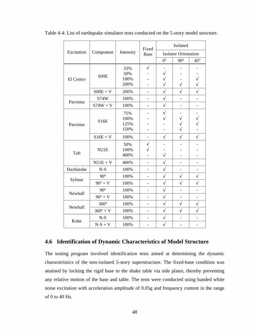
Table 4-4: List of earthquake simulator tests conducted on the 5-story model structure.
Isolated
Isolator Orientation Excitation Component Intensity
Fixed Base
0º 90º 45º
S00E
33% 50%
100% 200%
√ - - -
- √ √ √
- - - √
- - √ √
El Centro
S00E + V 200% - √ √ √ S74W 100% - √ - -
Pacoima S74W + V 100% - √ - -
S16E
75% 100% 125% 150%
- - - -
√ √ - -
- √ √ √
- √ √ -
Pacoima
S16E + V 100% - √ √ √
N21E 50%
100% 400%
√ √ -
- - √
- - -
- - - Taft
N21E + V 400% - √ - - Hachinohe N-S 100% - √ - -
90º 100% - √ √ √ Sylmar
90º + V 100% - √ √ √ 90º 100% - √ - -
Newhall 90º + V 100% - √ - -
360º 100% - √ √ √ Newhall
360º + V 100% - √ √ √ N-S 100% - √ - -
Kobe N-S + V 100% - √ - -
4.6 Identification of Dynamic Characteristics of Model Structure
The testing program involved identification tests aimed at determining the dynamic
characteristics of the non-isolated 5-story superstructure. The fixed-base condition was
attained by locking the rigid base to the shake table via side plates, thereby preventing
any relative motion of the base and table. The tests were conducted using banded white
noise excitation with acceleration amplitude of 0.05g and frequency content in the range
of 0 to 40 Hz.
48

The shapes, frequencies, and damping ratios of modes within the tested frequency range
were determined using modal identification techniques. The method is based on the
experimentally-recorded floor acceleration histories and frequency response of the floor
transfer functions (Bracci et al., 1992). The transfer function is defined as an output
structural response normalized by a superimposed input base motion in the frequency
domain. In particular, the transfer function for the j -th floor was obtained as the ratio of
the Fourier transform of recorded horizontal acceleration of the j -th floor to the Fourier
transform of the recorded base acceleration.
Equation (4-1) shows the general equation of motion of a base excited multi-degree-of-
freedom lumped mass structure.
[ ]{ } [ ]{ } [ ]{ } [ ]{ } ( )gM u C u K u M R u t+ + = − (4-1)
where [ ]M is the mass matrix, [ is the damping matrix, [ is the stiffness matrix;
, { , and { are the vectors of relative acceleration, velocity, and displacement of
the degrees of freedom, respectively; {
]C ]K
{ }u }u }u
}R is a unit vector; and is the ground (base)
acceleration history.
( )gu t
Expressing the displacement vector in terms of modal coordinates, : ky
(4-2) 1
{ } { }N
k kk
u φ=
= ∑ y
where { }kφ is the k -th mode shape and is the number of degrees of freedom. N
The amplitude of the acceleration transfer function of degree of freedom j may be
obtained as the amplitude of the ratio of the Fourier Transforms of the acceleration of
degree-of-freedom j to the acceleration of the ground:
2
2 21
(2 )( )2
Nk k k k
jk k k
iHi
ωξ ω ωjk
k
ω φω ω ωξ ω=
−Γ +=
− +∑ (4-3)
where kω and kξ are the -th mode frequency and damping ratio, k jkφ is the component
49

of mode shape kφ corresponding to the degree of freedom j , ω is frequency, and kΓ is
the -th modal participation factor given by k
{ } [ ]{ }{ } [ ]{ }
Tk
k Tk k
M RM
φφ φ
Γ = (4-4)
For a lightly damped structure, the -th peak of the amplitude of the transfer function
occurs at frequency
k
kω . Furthermore, if we assume well separated modes, the term in
front of jkφ in Equation (4-3) can be neglected for all frequencies kω ω≠ . Accordingly,
Equation (4-3) simplifies to
2(1 4 )( )
2k k
j k jkk
H ξω φξ
Γ += (4-5)
It should be noted that the peak of the j -th transfer function at the -th natural
frequency is proportional to the magnitude of the -th mode shape corresponding to the
k
k
j -th degree of freedom. The constant of proportionality is a function of the damping
ratio and modal participation factor for the -th mode. Since the constant of
proportionality is the same for all degrees of freedom for the -th mode, the ratio of the
peaks in the transfer functions for the different degrees of freedom at the -th natural
frequency are equal to the ratio of the mode shapes for the -th mode.
k
k
k
k
Thus the position and magnitude of the peaks of experimental transfer functions of all
degrees of freedom directly yield the frequencies and mode shapes. The phase angles for
the mode shapes can also be determined experimentally from the Fourier Transform of
the story accelerations as a function of the natural frequencies as
1 ( )( ) tan( )
ii
i
IR
ωθ ωω
− ⎛ ⎞= ⎜
⎝ ⎠⎟ (4-6)
where ( )iI ω and ( )iR ω are the imaginary and the real parts of the Fourier Amplitude of
the j -th story acceleration at the i -th frequency iω , respectively. Therefore, by
comparing the phase angles for each story at the natural frequencies, the mode shape
50
phases can be determined.
In addition, the corresponding damping ratios for the -th mode, k kξ , can be estimated
from the experimentally determined j -th story transfer function magnitude, -th mass
normalized mode shape at the
k
j -th degree of freedom, and the -th modal participation
factor as
k
122 ( )
4j kk
jk k
H ωξ
φ
−⎡ ⎤⎛ ⎞⎢ ⎥⎜ ⎟=⎜ ⎟
−⎢ ⎥Γ⎝ ⎠⎣ ⎦
(4-7)
Figure 4-14 presents the experimentally obtained acceleration transfer function
amplitudes for banded (0-40 Hz) white noise base excitation. These transfer functions
were used to extract the dynamic characteristics reported in Table 4-5.
The dynamic characteristics of the fixed-base structure were also analytically determined
using the program SAP2000 (Computers and Structures, 1998). The first three mode
shapes are graphically portrayed in Figure 4-15 and all extracted data pertinent to the
superstructure identification (natural frequencies, damping ratios, and mode shapes) are
listed in Table 4-5. The agreement between experimentally derived and analytically
calculated modal characteristics is excellent.
51
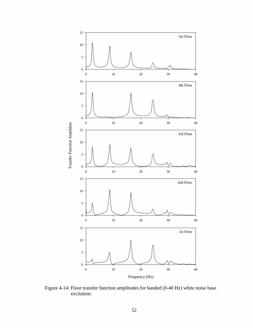
0 10 20 30 400
5
10
155th Floor
0 10 20 30 400
5
10
15
0 10 20 30 40
Tran
sfer
Fun
ctio
n A
mpl
idut
e
0
5
10
15
0 10 20 30 400
5
10
15
Frequency (Hz)
0 10 20 30 400
5
10
15
4th Floor
3rd Floor
2nd Floor
1st Floor
Figure 4-14: Floor transfer function amplitudes for banded (0-40 Hz) white noise base excitation.
52
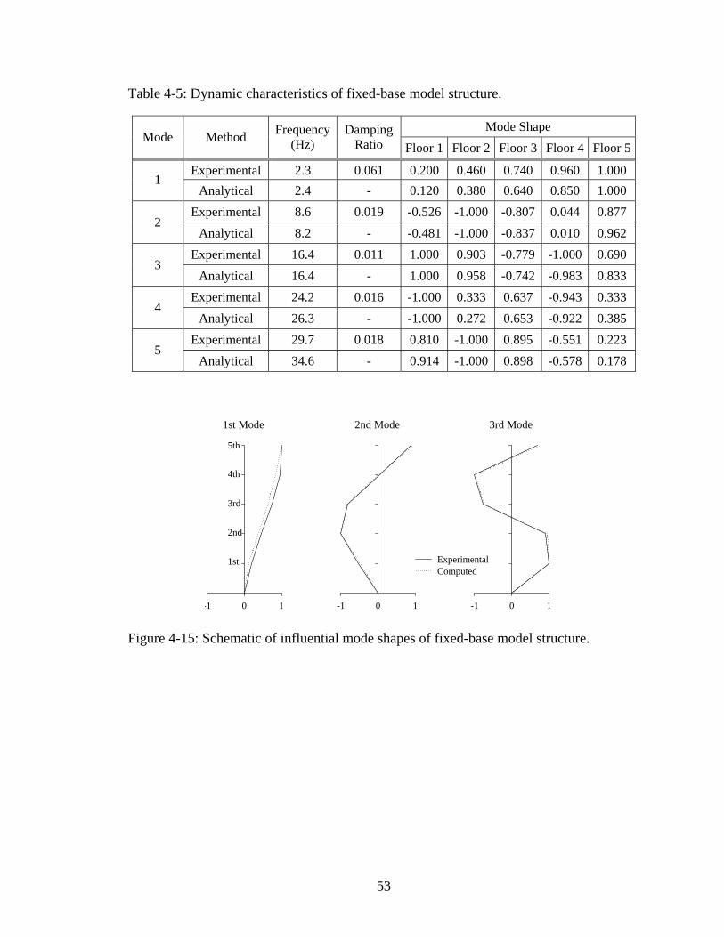
Table 4-5: Dynamic characteristics of fixed-base model structure.
Mode Shape Mode Method Frequency
(Hz) Damping
Ratio Floor 1 Floor 2 Floor 3 Floor 4 Floor 5
Experimental 2.3 0.061 0.200 0.460 0.740 0.960 1.000 1
Analytical 2.4 - 0.120 0.380 0.640 0.850 1.000 Experimental 8.6 0.019 -0.526 -1.000 -0.807 0.044 0.877
2 Analytical 8.2 - -0.481 -1.000 -0.837 0.010 0.962
Experimental 16.4 0.011 1.000 0.903 -0.779 -1.000 0.690 3
Analytical 16.4 - 1.000 0.958 -0.742 -0.983 0.833 Experimental 24.2 0.016 -1.000 0.333 0.637 -0.943 0.333
4 Analytical 26.3 - -1.000 0.272 0.653 -0.922 0.385
Experimental 29.7 0.018 0.810 -1.000 0.895 -0.551 0.223 5
Analytical 34.6 - 0.914 -1.000 0.898 -0.578 0.178
-1 0 1-1 0 1
ExperimentalComputed
-1 0 1
1st Mode 2nd Mode 3rd Mode
5th
4th
3rd
2nd
1st
Figure 4-15: Schematic of influential mode shapes of fixed-base model structure.
53


SECTION 5
EARTHQUAKE SIMULATOR TESTING RESULTS
5.1 Introduction
The results of the earthquake simulator testing program described in Section 4 are
presented in this section. The range of tests performed on the model structure provides
evidence for the effectiveness of the newly introduced isolator in uplift prevention. In
addition, the experimental response data form the basis for comparison with and
validation of the analytical predictions presented in Section 7.
5.2 Test Results
The experimental results for the five-story isolated model structure are summarized in
Tables 5-1 through 5-3. These tables present the experimentally recorded peak structure
response in three different bearing orientations, namely at 0-, 45-, and 90-degree angle of
lower bearing beam with respect to the direction of excitation. The excitation is identified
with a percentage figure which denotes a scaling factor on the actual acceleration record.
The parameters reported in Tables 5-1 to 5-3 refer to peak shake table motion, peak
isolation system response, and peak superstructure response. In particular, the quantities
reported concern:
1. Peak values of horizontal shake table motion in terms of acceleration, velocity, and
displacement. The accelerations and displacements are products of direct instrument
recordings, as opposed to the velocities which were derived from the displacement
records by numerical differentiation.
2. Peak isolation system response in terms of:
• Isolation system displacement: the initial, maximum, minimum, travel, and
permanent values of the average of east and west base displacement with respect
to the shake table. The displacement transducers monitoring the base
displacement were not initialized prior to each test, thus yielding correct
information on the initial and permanent displacement of the isolation system.
55

Apparently, the initial displacement in any test is identical to the permanent
displacement from the immediate previous test. Figure 5-1 exemplifies a typical
isolation system displacement history. The maximum travel displacement of the
isolation system is readily calculated as
{ }, max , travel max max in min inU U U U= − − U (5-1)
Time
Isol
atio
n Sy
stem
Dis
plac
emen
t
Permanent Disp.
Initial Disp.
Maximum Travel Disp.
Maximum Disp.
Minimum Disp.
Figure 5-1: Typical isolation system displacement history.
• Base shear: the force at the isolation system level calculated as the peak value of
the sum of recorded 1st-story shear and base inertial force. The inertial force at
base level was calculated as the product of the base reactive mass and the average
of the ABE and ABW recordings of base acceleration.
• Bearing axial load: the maximum and minimum values of total axial load in
bearing due to both static load and dynamic load from overturning moment effects
and vertical input motion. The axial load in the isolator was calculated based on
Equation (2-11). The additional axial force due to overturning moment effects,
, was obtained by using the overturning moment, OMN OM , calculated from
records of floor acceleration as follows:
5
1
Ij j
jOOM
F hMNL L
== ± = ±∑
(5-2)
where is the inertia force of floor , with and being the floor Ij jF m a= j j jm ja
56

mass and recorded floor acceleration, respectively; is the height of floor
with respect to the base; and is the frame span. Negative values indicate
compression and positive values indicate tension.
jh j
L
3. Peak superstructure response in terms of:
• 1st-story shear: the peak value of the recorded 1st-story shear from strain gauge
load cells.
• Story drift: the peak value of the difference between the average displacement
time histories of two adjacent floors, normalized by the story height.
To assess the accuracy of important recordings, measurements were contrasted with
corresponding calculated quantities. For example, to check the direct acceleration
measurements, recorded floor absolute displacements were double-differentiated to
obtain floor acceleration histories. In addition, the first-story shear was calculated by
summing up floor inertia forces (product of floor mass and floor acceleration above and
inclusive of the first story) and compared to the recorded first-story shear from strain
gauge load cells. Along the same lines, the isolation system shear (base shear) was
calculated based solely on floor/base acceleration recordings and compared to the value
obtained by adding the recorded 1st-story shear and base inertia force. The
aforementioned comparisons provide satisfactory evidence of the fidelity of the
experimental results.
5.3 Interpretation of Results
During the initial phase of testing of the five-story model in its isolated condition it was
observed that the system had undergone rocking. This was attributed to small
imperfections inflicted upon the isolation system during installation. That is, the four
isolators were not evenly aligned vertically below the rigid base. The problem was
promptly resolved by inserting metallic shims between the isolators and the base plate.
Due to the light weight of the model structure, the bearing pressures were very small, and
modest changes in axial load produced a large variation in the frictional properties of the
isolation system. Indeed, in view of Equation (3-2) and supportive evidence from testing
57

Tabl
e 5-
1: E
xper
imen
tally
reco
rded
pea
k st
ruct
ure
resp
onse
for i
sola
tor a
ngle
of 0
º.
Hor
izon
tal T
able
Mot
ion
Isol
atio
n Sy
stem
Res
pons
e Su
pers
truct
ure
Res
pons
e
Dis
plac
emen
t B
earin
g A
xial
Loa
dTe
st
Ex
cita
tion
Acc
el.
(g)
Vel
. (m
m/s
)D
isp.
(m
m)
Initi
al(m
m)
Max
. (m
m)
Min
. (m
m)
Trav
el
(mm
) Pe
rm.
(mm
)
Bas
e Sh
ear/
Wei
ght
(-)
Max
. (k
N)
Min
. (k
N)
1st-s
tory
Shea
r/ W
eigh
t (-
)
Stor
y1 D
rift/
Hei
ght
(%)
IELH
50A
El
Cen
tro S
00E
50%
0.
21
82
13
-14.
5 -2
.7
-21.
2 11
.8
-7.5
0.
07
42.8
310
.41
0.10
0.
25 (2
)IE
LH10
0A
El C
entro
S00
E 10
0%
0.35
15
8 27
0.
1 9.
2 -2
3.7
23.8
-0
.4
0.08
45
.51
7.73
0.
12
0.33
(2)
IELH
200A
El
Cen
tro S
00E
200%
0.
56
301
55
-0.4
31
.2
-55.
1 54
.7
-7.5
0.
11
51.3
51.
88
0.16
0.
40 (2
)IE
LB20
0A
El C
entro
S00
E+V
200
%
0.55
29
9 54
1.
0 23
.0
-51.
8 52
.8
0.2
0.13
58
.02
0.49
0.
17
0.45
(2)
ITFH
400A
Ta
ft N
21E
400%
0.
64
257
56
3.5
41.5
-1
7.3
38
.0-1
.80.
1253
.64
-0.4
00.
160.
64 (2
)IT
FB40
0A
Taft
N21
E+V
400
%
0.63
25
9 56
-1
.7
40.7
-1
9.4
42.5
-2
.2
0.15
61
.48
-10.
820.
21
0.77
(2)
IN9H
100A
N
ewha
ll 90
º 100
%
0.79
28
7 43
4.
9 22
.1
-27.
8
32.7
-2.8
0.13
49.2
04.
040.
150.
43 (2
)IN
9B10
0A
New
hall
90º+
V 1
00%
0.
78
289
43
-2.8
20
.2
-27.
4 24
.6
-0.3
0.
14
58.3
9-2
.82
0.16
0.
48 (4
)IN
3H10
0A
New
hall
360º
100
%
0.76
42
8 58
-0
.3
49.0
-4
1.3
49
.4-2
.10.
1658
.63
-5.3
90.
210.
59 (4
)IN
3B10
0A
New
hall
360º
+V 1
00%
0.
74
428
58
-2.1
46
.8
-44.
5 48
.9
-1.1
0.
16
66.3
8-1
6.29
0.22
0.
64 (4
)IS
YH
100A
Sy
lmar
90º
100
%
0.64
33
2 49
1.
3 57
.7
-22.
8 56
.4
3.9
0.16
57
.81
-4.5
7 0.
17
0.51
(4)
ISY
B10
0A
Sylm
ar 9
0º+V
100
%
0.65
33
2 49
3.
9 56
.4
-23.
9 52
.6
4.9
0.16
71
.47
-9.5
2 0.
22
0.46
(3)
IKB
H10
0A
Kob
e N
-S 1
00%
0.
75
434
42
-1.1
26
.4
-37.
8 36
.7
-0.3
0.
14
59.1
7-5
.93
0.18
0.
81 (2
)IK
BB
100A
K
obe
N-S
+V 1
00%
0.
76
432
42
-0.3
31
.8
-32.
2 32
.0
0.7
0.17
72
.79
-5.9
6 0.
22
0.67
(2)
IP7H
100A
Pa
coim
a S7
4W 1
00%
0.
77
268
28
0.2
26.0
-3
0.7
30.9
-1
.0
0.12
51
.87
1.36
0.
15
0.36
(2)
IP7B
100A
Pa
coim
a S7
4W+V
100
%
0.75
27
0 28
-0
.9
27.2
-2
9.0
28.1
-5
.7
0.15
69
.26
-24.
330.
16
0.50
(3)
IP1H
75A
Pa
coim
a S1
6E 7
5%
0.64
34
8 59
-4
.3
43.9
-4
9.7
48.2
1.
0 0.
13
48.0
65.
17
0.15
0.
35 (2
)IP
1H10
0A
Paco
ima
S16E
100
%
0.80
46
1 79
1.
0 56
.5
-72.
5 73
.5
3.9
0.14
50
.56
2.67
0.
16
0.37
(2)
IP1B
100A
Pa
coim
a S1
6E+V
100
%
0.80
46
0 78
3.
9 61
.2
-68.
1 72
.0
3.6
0.21
66
.71
-1.9
0 0.
17
0.51
(3)
IHA
H10
0A
Hac
hino
he N
-S 1
00%
0.
24
131
31
-2.2
15
.3
-5.6
17.6
1.3
0.11
46.5
56.
680.
140.
35 (4
)
58
1
Val
ue in
par
enth
esis
is st
ory
at w
hich
pea
k va
lue
was
reco
rded
.

Tabl
e 5-
2: E
xper
imen
tally
reco
rded
pea
k st
ruct
ure
resp
onse
for i
sola
tor a
ngle
of 9
0º.
Hor
izon
tal T
able
Mot
ion
Isol
atio
n Sy
stem
Res
pons
e Su
pers
truct
ure
Res
pons
e
Dis
plac
emen
t B
earin
g A
xial
Loa
dTe
st
Ex
cita
tion
Acc
el.
(g)
Vel
. (m
m/s
)D
isp.
(m
m)
Initi
al(m
m)
Max
. (m
m)
Min
. (m
m)
Trav
el
(mm
) Pe
rm.
(mm
)
Bas
e Sh
ear/
Wei
ght
(-)
Max
. (k
N)
Min
. (k
N)
1st-s
tory
Shea
r/ W
eigh
t (-
)
Stor
y1 D
rift/
Hei
ght
(%)
IELH
100B
El
Cen
tro S
00E
100%
0.
33
149
26
0.0
8.8
-16.
1 16
.1
1.8
0.18
52
.86
0.38
0.
19
0.45
(2)
IELH
200C
El
Cen
tro S
00E
200%
0.
56
288
53
9.9
20.0
-5
2.2
62.1
-4
.7
0.11
53
.61
-0.3
7 0.
17
0.52
(2)
IELB
200C
El
Cen
tro S
00E+
V 2
00%
0.
54
291
53
-4.7
18
.6
-45.
9 41
.1
-4.1
0.
14
63.5
0-5
.01
0.22
0.
45 (2
)IN
3H10
0C
New
hall
360º
100
%
0.75
41
9 57
10
.1
43.8
-3
2.0
42.0
-1.7
0.14
63.4
5-1
0.21
0.24
0.69
(2)
IN3B
100C
N
ewha
ll 36
0º+V
100
%
0.72
41
7 57
-1
.7
43.5
-4
1.4
45.1
-2
.9
0.16
63
.11
-19.
300.
22
0.66
(2)
ISY
H10
0C
Sylm
ar 9
0º 1
00%
0.
62
327
48
4.6
54.5
-2
1.9
49.9
8.
1 0.
15
60.0
1-6
.77
0.18
0.
51 (2
)IS
YB
100C
Sy
lmar
90º
+V 1
00%
0.
64
325
48
8.1
54.6
-2
0.1
46.5
10
.1
0.19
79
.66
-24.
070.
24
0.46
(3)
IP1H
100C
Pa
coim
a S1
6E 1
00%
0.
79
457
77
5.7
49.2
-6
7.5
73.3
3.
9 0.
16
51.3
31.
91
0.18
0.
40 (2
) IP
1H12
5C
Paco
ima
S16E
125
%
1.01
56
5 97
-2
.9
66.0
-9
4.5
91.6
7.
9 0.
19
58.1
9-4
.95
0.17
0.
50 (2
)IP
1B10
0C
Paco
ima
S16E
+V 1
00%
0.
79
451
77
3.9
54.8
-6
4.6
68.6
4.
6 0.
23
80.1
4-9
.05
0.20
0.
55 (3
)
59
1 V
alue
in p
aren
thes
is is
stor
y at
whi
ch p
eak
valu
e w
as re
cord
ed.
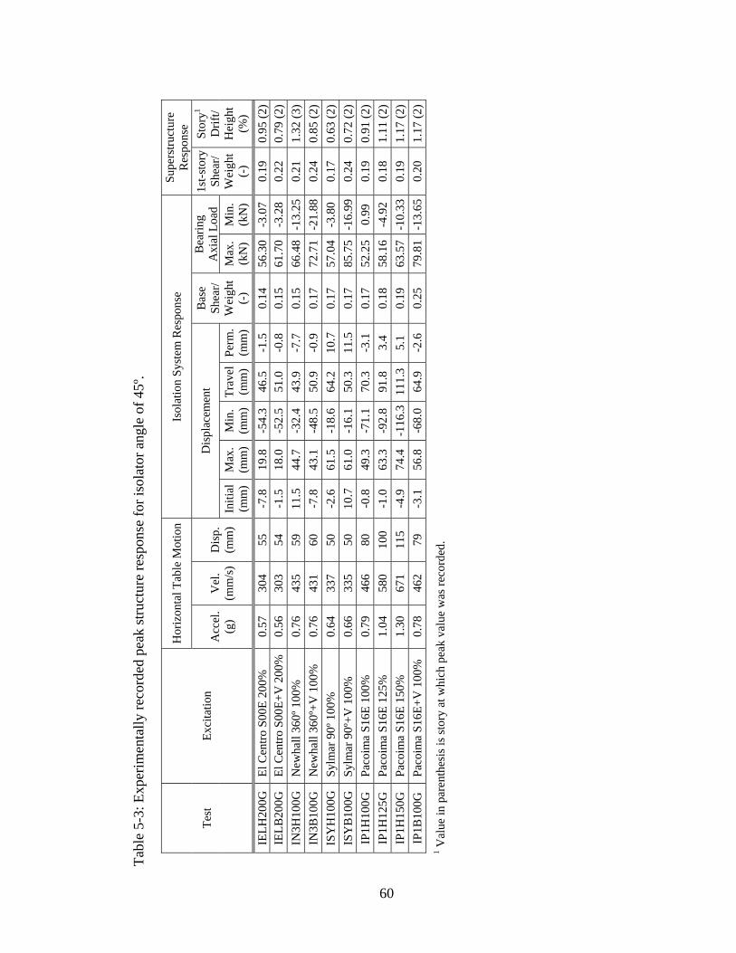
Tabl
e 5-
3: E
xper
imen
tally
reco
rded
pea
k st
ruct
ure
resp
onse
for i
sola
tor a
ngle
of 4
5º.
Hor
izon
tal T
able
Mot
ion
Isol
atio
n Sy
stem
Res
pons
e Su
pers
truct
ure
Res
pons
e
Dis
plac
emen
t B
earin
g A
xial
Loa
dTe
st
Ex
cita
tion
Acc
el.
(g)
Vel
. (m
m/s
)D
isp.
(m
m)
Initi
al(m
m)
Max
. (m
m)
Min
. (m
m)
Trav
el
(mm
) Pe
rm.
(mm
)
Bas
e Sh
ear/
Wei
ght
(-)
Max
. (k
N)
Min
. (k
N)
1st-s
tory
Shea
r/ W
eigh
t (-
)
Stor
y1 D
rift/
Hei
ght
(%)
IELH
200G
El
Cen
tro S
00E
200%
0.
57
304
55
-7.8
19
.8
-54.
3 46
.5
-1.5
0.
14
56.3
0-3
.07
0.19
0.
95 (2
)IE
LB20
0G
El C
entro
S00
E+V
200
%
0.56
30
3 54
-1
.5
18.0
-5
2.5
51.0
-0
.8
0.15
61
.70
-3.2
8 0.
22
0.79
(2)
IN3H
100G
N
ewha
ll 36
0º 1
00%
0.
76
435
59
11.5
44
.7
-32.
4
43
.9-7
.70.
1566
.48
-13.
250.
211.
32 (3
)IN
3B10
0G
New
hall
360º
+V 1
00%
0.
76
431
60
-7.8
43
.1
-48.
5 50
.9
-0.9
0.
17
72.7
1-2
1.88
0.24
0.
85 (2
)IS
YH
100G
Sy
lmar
90º
100
%
0.64
33
7 50
-2
.6
61.5
-1
8.6
64.2
10
.7
0.17
57
.04
-3.8
0 0.
17
0.63
(2)
ISY
B10
0G
Sylm
ar 9
0º+V
100
%
0.66
33
5 50
10
.7
61.0
-1
6.1
50.3
11
.5
0.17
85
.75
-16.
990.
24
0.72
(2)
IP1H
100G
Pa
coim
a S1
6E 1
00%
0.
79
466
80
-0.8
49
.3
-71.
1 70
.3
-3.1
0.
17
52.2
50.
99
0.19
0.
91 (2
)IP
1H12
5G
Paco
ima
S16E
125
%
1.04
58
0 10
0 -1
.0
63.3
-9
2.8
91.8
3.
4 0.
18
58.1
6-4
.92
0.18
1.
11 (2
)IP
1H15
0G
Paco
ima
S16E
150
%
1.30
67
1 11
5 -4
.9
74.4
-1
16.3
111.
3 5.
1 0.
19
63.5
7-1
0.33
0.19
1.
17 (2
)IP
1B10
0G
Paco
ima
S16E
+V 1
00%
0.
78
462
79
-3.1
56
.8
-68.
0 64
.9
-2.6
0.
25
79.8
1-1
3.65
0.20
1.
17 (2
)
60
1 V
alue
in p
aren
thes
is is
stor
y at
whi
ch p
eak
valu
e w
as re
cord
ed.
of individual isolator presented in Section 3, the lower the bearing pressure, the less
stable the frictional properties. This peculiarity of noticeable uncertainty in frictional
properties refers only to the laboratory model at hand and does not apply for real-life
applications, where the design is carried out for high loads.
Because of the low contact pressure, the XY-FP isolators exhibited initially high sliding
coefficient of friction, in the range of 0.12-0.15, limiting the isolation system
performance. Accordingly, in order to render the isolation system more effective to
facilitate larger displacements, successive lubrication of the bearing sliding interface was
attempted during the testing program. The lubrication process resulted in a coefficient of
friction in the range of 0.06 to 0.10. However, by virtue of the superficial application of
the lubricant, the reduction in friction was not permanent and the coefficient of friction
gradually increased with repeated testing as lubricant was lost, thus necessitating
repetitive lubrication.
In general, the shake table produced motions that are in acceptable agreement with the
target motions in the period range of the isolated model structure. However, it is worth
noting that the recorded histories of the table motion were not accurately reproduced
among tests with inputs that were specified to be identical. This can be seen from the
peak values of the generated table motion presented in Tables 5-1 through 5-3. This
ambiguity can be explained along the lines of shake table-structure interaction.
Furthermore, the shake table underwent perceptible vertical motion even when only
horizontal table motion was imposed. Again, this can be interpreted as evidence of shake
table-structure interaction during testing. The implications of this phenomenon were, in
effect, to increase the severity of the testing by aggravating the earthquake induced axial
load (compression and tension) on the bearings.
One can observe from Tables 5-1 through 5-3 that the permanent displacement of the
isolation system along the excitation direction was small and not cumulative in
successive tests. Figure 5-2 depicts graphically the history of the permanent
displacements from testing in different isolator orientations. Evidently, the tested XY-FP
isolator provided sufficient restoring force and prevented permanent displacements to
accumulate to unacceptable levels.
61
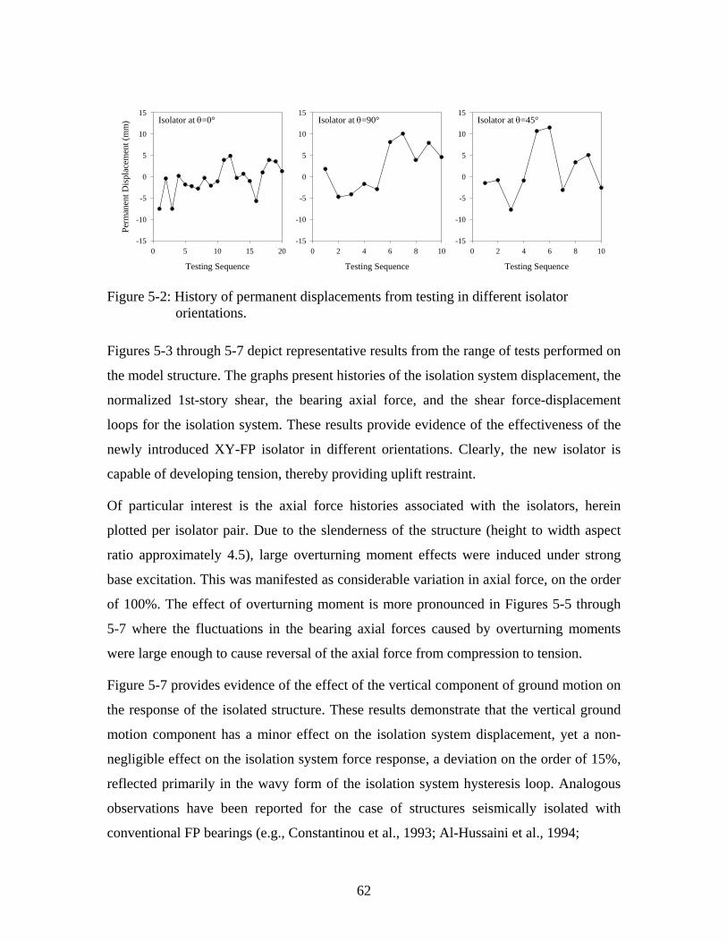
Testing Sequence
0 2 4 6 8 10-15
-10
-5
0
5
10
15Isolator at θ=90°
Testing Sequence
0 5 10 15 20
Perm
anen
t Dis
plac
emen
t (m
m)
-15
-10
-5
0
5
10
15
Testing Sequence
0 2 4 6 8 10-15
-10
-5
0
5
10
15Isolator at θ=0° Isolator at θ=45°
Figure 5-2: History of permanent displacements from testing in different isolator orientations.
Figures 5-3 through 5-7 depict representative results from the range of tests performed on
the model structure. The graphs present histories of the isolation system displacement, the
normalized 1st-story shear, the bearing axial force, and the shear force-displacement
loops for the isolation system. These results provide evidence of the effectiveness of the
newly introduced XY-FP isolator in different orientations. Clearly, the new isolator is
capable of developing tension, thereby providing uplift restraint.
Of particular interest is the axial force histories associated with the isolators, herein
plotted per isolator pair. Due to the slenderness of the structure (height to width aspect
ratio approximately 4.5), large overturning moment effects were induced under strong
base excitation. This was manifested as considerable variation in axial force, on the order
of 100%. The effect of overturning moment is more pronounced in Figures 5-5 through
5-7 where the fluctuations in the bearing axial forces caused by overturning moments
were large enough to cause reversal of the axial force from compression to tension.
Figure 5-7 provides evidence of the effect of the vertical component of ground motion on
the response of the isolated structure. These results demonstrate that the vertical ground
motion component has a minor effect on the isolation system displacement, yet a non-
negligible effect on the isolation system force response, a deviation on the order of 15%,
reflected primarily in the wavy form of the isolation system hysteresis loop. Analogous
observations have been reported for the case of structures seismically isolated with
conventional FP bearings (e.g., Constantinou et al., 1993; Al-Hussaini et al., 1994;
62

0 5 10 15 20 25
Axi
al F
orce
(kN
)
-50
0
50
100
150
0 5 10 15 20 25
1st-S
tory
She
ar /
Wei
ght
-0.2
-0.1
0.0
0.1
0.2
0 5 10 15 20 25
Isol
atio
n Sy
stem
D
ispl
acem
ent (
mm
)
-60-40-20
0204060
Test IELH200A: El Centro S00E 200%, Isolators at θ=0o
Isolation System Displacement (mm)-60 -40 -20 0 20 40 60
Bas
e Sh
ear /
Wei
ght
-0.2
-0.1
0.0
0.1
0.2
Time (sec)0 5 10 15 20 25
Axi
al F
orce
(kN
)
-50
0
50
100
150
South Isolator Pair
North Isolator Pair
Weight = 106.5 kN
TENSION
TENSION
Figure 5-3: Experimental results in El Centro S00E 200% for bearing orientation of 0°.
63

0 5 10 15
Axi
al F
orce
(kN
)
-50
0
50
100
150
0 5 10 15
1st-S
tory
She
ar /
Wei
ght
-0.3-0.2-0.10.00.10.20.3
0 5 10 15
Isol
atio
n Sy
stem
D
ispl
acem
ent (
mm
)
-60-40-20
0204060
Test IN3H100A: Newhall 360 100%, Isolators at θ=0 o
Isolation System Displacement (mm)-60 -40 -20 0 20 40 60
Bas
e Sh
ear /
Wei
ght
-0.3-0.2-0.10.00.10.20.3
Time (sec)0 5 10 15
Axi
al F
orce
(kN
)
-50
0
50
100
150
South Isolator Pair
North Isolator Pair
Weight = 106.5 kN
TENSION
TENSION
Figure 5-4: Experimental results in Newhall 360 100% for bearing orientation of 0°.
64
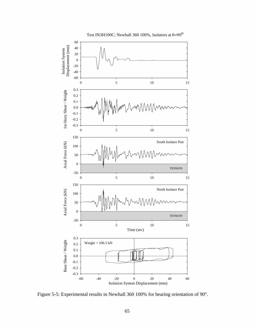
0 5 10 15
Axi
al F
orce
(kN
)
-50
0
50
100
150
0 5 10 15
1st-S
tory
She
ar /
Wei
ght
-0.3-0.2-0.10.00.10.20.3
0 5 10 15
Isol
atio
n Sy
stem
D
ispl
acem
ent (
mm
)
-60-40-20
0204060
Test IN3H100C: Newhall 360 100%, Isolators at θ=90 o
Isolation System Displacement (mm)-60 -40 -20 0 20 40 60
Base
She
ar /
Wei
ght
-0.3-0.2-0.10.00.10.20.3
Time (sec)0 5 10 15
Axi
al F
orce
(kN
)
-50
0
50
100
150
South Isolator Pair
North Isolator Pair
Weight = 106.5 kN
TENSION
TENSION
Figure 5-5: Experimental results in Newhall 360 100% for bearing orientation of 90°.
65

0 5 10 15
Axi
al F
orce
(kN
)
-50
0
50
100
150
0 5 10 15
1st-S
tory
She
ar /
Wei
ght
-0.3-0.2-0.10.00.10.20.3
0 5 10 15
Isol
atio
n Sy
stem
D
ispl
acem
ent (
mm
)
-60-40-20
0204060
Test IN3H100G: Newhall 360 100%, Isolators at θ=45 o
Isolation System Displacement (mm)-60 -40 -20 0 20 40 60
Base
She
ar /
Wei
ght
-0.3-0.2-0.10.00.10.20.3
Time (sec)0 5 10 15
Axi
al F
orce
(kN
)
-50
0
50
100
150
South Isolator Pair
North Isolator Pair
Weight = 106.5 kN
TENSION
TENSION
Figure 5-6: Experimental results in Newhall 360 100% for bearing orientation of 45°.
66
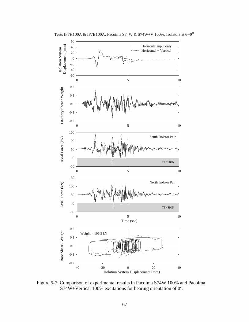
0 5 10
Axi
al F
orce
(kN
)
-50
0
50
100
150
0 5 10
1st-S
tory
She
ar /
Wei
ght
-0.2
-0.1
0.0
0.1
0.2
0 5 10
Isol
atio
n Sy
stem
D
ispl
acem
ent (
mm
)
-60-40-20
0204060
Horizontal input onlyHorizontal + Vertical
Tests IP7H100A & IP7B100A: Pacoima S74W & S74W+V 100%, Isolators at θ=0o
Isolation System Displacement (mm)-40 -20 0 20 40
Bas
e Sh
ear /
Wei
ght
-0.2
-0.1
0.0
0.1
0.2
Time (sec)0 5 10
Axi
al F
orce
(kN
)
-50
0
50
100
150
South Isolator Pair
North Isolator Pair
Weight = 106.5 kN
TENSION
TENSION
Figure 5-7: Comparison of experimental results in Pacoima S74W 100% and Pacoima S74W+Vertical 100% excitations for bearing orientation of 0°.
67

Kasalanati et al., 1999; Mosqueda et al., 2004). The effect of the vertical component of
ground motion is pronounced in the local response of the isolators. In effect, the vertical
ground acceleration modifies the axial load on the bearing (Equation (2-11)), and
therefore impacts both the restoring force and the friction force in the bearing constitutive
relationship (Equation (2-7)). A parallel implication of the variation of the bearing
pressure at the sliding interface is the modification of the coefficient of friction (see
section 3.2). Figure 5-7 demonstrates that the amplification of the bearing axial force due
to the vertical input may prove large enough to cause tension to develop in the bearing.
It is worth observing that the peak axial load on the bearing occurs at a large lateral
displacement but not exactly at the instant of peak isolation displacement. Upon noting
that the bearing axial load is directly related to overturning moment, and hence to floor
accelerations, the aforementioned discrepancy can be attributed to the fact that floor
acceleration response was out of phase (higher mode response). Similar observations on
floor acceleration profiles and their impact on the response of FP-isolated structures were
also reported by Mokha et al. (1990) and Al-Hussaini et al. (1994).
68
SECTION 6
MODIFICATION OF PROGRAM 3D-BASIS-ME
6.1 Introduction
Section 6 outlines the modifications made to computer program 3D-BASIS-ME
(Tsopelas et al., 1994). While maintaining the key features of the program, the following
enhancements are incorporated: (i) a new hysteretic element capable of modeling the
behavior of the XY-FP isolator; (ii) a capability of accounting for initial non-zero
displacement of the isolators; and (iii) a more accurate description of the additional
bearing axial forces due to global overturning moment effects.
6.2 Overview of Program 3D-BASIS
The 3D-BASIS suite of computer programs was developed for the nonlinear dynamic
analysis of three-dimensional seismically isolated structures. Capable of modeling
various types of isolation devices with strong nonlinearities, 3D-BASIS provides a
versatile tool for analysis and design of complex structures with modern isolation
systems. As such, the program contributed in the verification and development of new
standards for design of base isolated structures and facilitated the advancement of
practical application of base isolation.
Rooted in the core philosophy of its predecessors, 3D-BASIS-ME represents an enhanced
version of program 3D-BASIS-M (Tsopelas et al. 1991), which is a further extension of
the original program 3D-BASIS (Nagarajaiah et al. 1989, 1991b and 1993).
Program 3D-BASIS-M is an improvement on the original version by offering the
capability to analyze multiple superstructures on a single isolation basemat. This could be
exploited, for example, in dynamic analysis of isolated structures consisting of several
parts separated by thermal expansion joints, or isolated liquid storage tanks in which the
liquid-tank system is modeled by two multi-degree-of freedom systems representing the
impulsive and convective effects, respectively.
Program 3D-BASIS-ME augments the potential of its predecessor by introducing new
69

elements for modeling Friction Pendulum (FP) bearings, high damping rubber bearings
with stiffening behavior, and nonlinear viscous dampers. Furthermore, it accounts for the
effects of vertical ground motion and overturning moment on the behavior of sliding
bearings.
Assumed to remain elastic at all times, the superstructure in 3D-BASIS-ME can be
modeled via (i) a shear-type representation, or (ii) a full three-dimensional representation.
In the shear-type representation, the stiffness matrix of the superstructure is internally
constructed by the program, based on input story translational stiffnesses, rotational
stiffness, and eccentricities of center of resistance with respect to the center of mass for
each floor. It is assumed that the centers of mass of all floors lie on a common vertical
axis, floors are rigid, and walls and columns are inextensible. In the full three-
dimensional representation, the dynamic characteristics of the superstructure in terms of
frequencies and mode shapes are determined externally by other computer programs and
imported to program 3D-BASIS-ME. In this way, the extensibility of the vertical
elements, arbitrary location of centers of mass, and floor flexibility may be implicitly
accounted for. In both options, each floor mass is lumped into a single point mass having
three degrees of freedom (two lateral and one torsional) in the horizontal plane.
The isolation system is modeled with spatial distribution and explicit nonlinear force-
displacement characteristics of the individual isolators. The isolation devices are
considered rigid in the vertical direction and are assumed to have negligible resistance to
torsion. 3D-BASIS-ME has the following elements for modeling the behavior of an
isolator: (i) linear elastic element; (ii) linear and nonlinear viscous element for fluid
viscous dampers or other devices displaying viscous behavior; (iii) hysteretic element for
elastomeric bearings and steel dampers; (iv) stiffening (biaxial) hysteretic element for
high damping rubber bearings; (v) hysteretic element for flat sliding bearings; and (vi)
hysteretic element for spherical sliding (FP) bearings.
The algorithm selected for the 3D-BASIS series is based on the solution of the equations
of motion using a combination of Newmark’s integration method and a fourth-order
Runge-Kutta scheme, complemented by a pseudo-load formulation and time marching
procedure for accuracy and efficiency. The algorithm has been proven to be suitable for
70

analyzing highly nonlinear sliding isolation systems (Nagarajaiah et al., 1989, 1990,
1991a, 1991b).
6.3 Enhancements Introduced in Program 3D-BASIS-ME
While maintaining the key features of the program, the following enhancements were
incorporated into 3D-BASIS-ME: (i) a new hysteretic element capable of modeling the
behavior of the XY-FP isolator; (ii) a capability of accounting for initial non-zero
displacement of the isolators; and (iii) a more accurate description of the additional
bearing axial forces due to overturning moment effects.
6.3.1 New Hysteretic Element for XY-FP Isolator
The mathematical model of the new XY-FP isolator has been established in Section 2.3.
The force-displacement constitutive relationship, neglecting the interaction between
lateral force and friction force, is given by Equation (2-10). To accommodate the
mechanical behavior of the new XY-FP isolator, a new hysteretic element was
incorporated into 3D-BASIS-ME. The new element is synthesized by two independent
uniaxial hysteretic elements allowing different frictional interface properties along the
principal isolator directions. It should be emphasized that, contrary to the element
representing the conventional FP isolator, the new element is capable of developing
tension. Moreover, different frictional interface properties can be assumed under
compressive and tensile isolator normal force.
In general, under harmonic or transient dynamic loading each sliding bearing undergoes
different motion requiring multiple stick-slip conditions. Accordingly, the use of
Coulomb model (Su et al., 1987; Mostaghel and Khodaverdian, 1987; Younis et al.,
1983; Goodman, 1963) under these conditions is complicated. Hence the Bouc-Wen
plasticity model (Park et al., 1986; Wen, 1976) was adopted in modeling the XY-FP
isolator because of its computational efficiency, which stems from the fact that tracing of
the hysteresis loops in this model is not necessary.
The horizontal forces in the XY-FP element in 3D-BASIS-ME are given by
71

1 1 11
222 2
0000
F U NN RNN RF U
µµ
⎡ ⎤⎧ ⎫ ⎧ ⎫ ⎧ ⎫⎡ ⎤= +⎨ ⎬ ⎨ ⎬ ⎨ ⎬⎢ ⎥⎢ ⎥
⎣ ⎦⎩ ⎭ ⎩ ⎭ ⎩ ⎭⎣ ⎦
1
2
ZZ
(6-1)
where 1R and 2R are the radii of curvature of the lower and upper concave beams,
respectively; 1µ and 2µ are the associated sliding friction coefficients; and are
the displacements in local axis 1 and 2, respectively; is the normal force on the
bearing, positive when compressive; and
1U 2U
N
1Z and 2Z are hysteretic dimensionless
quantities governed by the following differential equations:
1 1 11 1 1 1
2 2 2 22 2 2
( sgn( ) ) 01 00 1 0 ( sgn( ) )
Z U ZZ Y UA
U
Z Y U Z U Z
η
η
γ β
γ β
⎡ ⎤⎧ ⎫ ⎧ ⎫ ⎧ ⎫+⎡ ⎤⎪ ⎪ ⎪ ⎪ ⎪ ⎪⎢ ⎥= −⎨ ⎬ ⎨ ⎬ ⎨ ⎬⎢ ⎥⎢ ⎥+⎪ ⎪ ⎣ ⎦ ⎪ ⎪ ⎪ ⎪⎩ ⎭ ⎩ ⎭ ⎩ ⎭⎣ ⎦ U
(6-2)
where and are the velocities in local axis 1 and 2, respectively; , 1U 2U A β , γ , and η
are dimensionless quantities that control the shape of the hysteresis loop; and and
represent displacement quantities.
1Y 2Y
Constantinou et al. (1990) have shown that when 1A = and 1β γ+ = , the model of
Equation (6-2) reduces to a model of viscoplasticity that was proposed by Ozdemir
(1976). In this case, and represent the yield displacements, while parameter 1Y 2Y η
controls the mode of transition into the inelastic range. The model exhibits rate
dependency, which reduces with increasing values of the exponent, η , and/or increasing
values of the ductility ratio (maximum value of ). /U Y
The conditions of separation and reattachment (stick-slip) are accounted for by variables
1Z and 2Z in Equation (6-2). In this respect, quantity iZ may be regarded as a
continuous approximation to the unit step function, in Equation (2-10). It should
be noted that during the sliding phase, whereas
sgn( )iU
= 1iZ ± 1iZ < during the sticking phase
(elastic behavior with very high stiffness).
A limitation of the employed plasticity model is its inability to reproduce truly rigid-
plastic behavior. However, since Teflon-steel interfaces undergo very small elastic
displacement before sliding, small value of yield displacement Y , in the range of 0.13-
72

0.50 mm (0.005-0.02 in.) can be reasonably assumed and, hence, the viscoplasticity
model can be used (Constantinou et al., 1990). The model exhibits insignificant rate
dependency for such low yield displacement and resulting ductility ratio, and for
parameter values of 2η = , 0.1β = , and 0.9γ = suggested by Constantinou et al. (1990).
It should be emphasized that Equation (6-2) is uncoupled, representing two independent
uniaxial hysteretic elements along the principal directions of the isolator. Accordingly,
the biaxial interaction between forces in the two orthogonal directions is nonexistent,
rendering the interaction surface to be square, as opposed to the circular interaction
surface for the biaxial behavior of the spherical FP isolator (Figure 6-1).
Figure 6-1: Force interaction curves for XY-FP and FP isolators.
Recall that in the case of the conventional FP isolator, an arbitrary uni-directional motion
entails a collinear resisting force. On the contrary, in the case of the XY-FP isolator,
application of a horizontal force in an arbitrary direction results in a bi-directional motion
realized along the two isolator beams. This is true even for orthotropic interface
conditions, namely for identical frictional and geometric properties along the two
component beams. An exception to this is when the applied force is either along a local
axis or at 45 degrees with respect to a local axis, wherein uni-directional motion results
along the corresponding force direction.
In Equation (6-1), the normal force, , on an isolation bearing is, in general, a varying
function of time due to the vertical component of ground motion and the overturning
moment effects. For vertically rigid structures, the normal force on the XY-FP bearing at
N
73

any given time is given by
1 gv OMu NN Wg W
⎛ ⎞= + +⎜
⎝ ⎠⎟ (6-3)
where is the weight acting on the isolator; W gvu is the vertical ground acceleration,
positive when directed upward; and is the additional axial force due to overturning
moment effects, positive when compressive.
OMN
The new element for the XY-FP isolator in 3D-BASIS-ME requires a user-supplied
subroutine, function FOVM, to calculate the additional axial force due to overturning
moment effects. The function – called by the main program at each time step – returns to
the main program the additional axial load FOVM on each bearing due to overturning
moment effects. The definition of the additional force FOVM due to the overturning
moments OVMX and OVMY is illustrated in Figure 6-2, in which FOVM is the normal
force due to overturning moment, positive when compressive; OVMX and OVMY are
the overturning moments about X- and Y-axis, respectively, positive in the direction
shown in the figure (Tsopelas et al., 1994).
Figure 6-2: Definition of overturning moments OVMX and OVMY, and additional force FOVM.
Contrary to the element representing the conventional FP isolator, the new element is
capable of capturing the uplift-restraint property of the XY-FP isolator allowing potential
reversal of the bearing axial force from compression to tension.
74
Moreover, the dependency of the coefficient of friction on sliding velocity and bearing
pressure is explicitly modeled in 3D-BASIS-ME according to Equations (3-1) and(3-2),
respectively.
Output data pertaining to the new element representing the XY-FP isolator are given in
file ISOL8. The output file contains response histories of individual XY-FP isolators, in
terms of (a) isolator shear forces in both local and global axes; (b) isolator axial forces;
and (c) isolator displacements in both local and global axes.
6.3.2 Account for initial non-zero displacement of the isolators
The potentiality of permanent displacements in sliding isolation systems with reduced
restoring force capability, or lack thereof, is often of concern, as the permanent
displacements may accumulate to unacceptable levels in successive earthquakes (Roussis
et al., 2002, 2003; Constantinou et al., 1991). Building codes and guide specifications for
seismic isolation design, attempt to account for this possibility by either specifying
minimum stiffness requirements or by penalizing systems with insufficient stiffness.
To accommodate monitoring of the history of residual displacements in successive
analyses, 3D-BASIS-ME was modified to account for initial non-zero displacements of
the isolation system resulting from the permanent displacements in the immediate
previous analysis. This option, available for the new XY-FP element, allows for input of
the initial state of the isolation system in terms of the initial displacements along the X
and Y directions and initial rotation of the center of mass of the base.
6.3.3 A more accurate description of the additional bearing axial forces due to overturning moment effects
A user-supplied subroutine, FOVM, is available in program 3D-BASIS-ME which
accounts for the variability of axial forces in the isolation bearings due to overturning
moment effects (Tsopelas et al., 1994). The function, which shall be modified by the user
before each run, updates and returns to the main program the additional axial load FOVM
on bearing i at every time step. The function assumes a unique relation between
overturning moments and additional axial load on bearings. It should be noted that this is
a simplification of a complex phenomenon, yet it is a commonly used engineering
75

approximation.
In order to provide a more accurate representation of bearing axial forces, 3D-BASIS-ME
was modified to include a direct relationship between floor inertia forces and additional
axial load on bearings. At each time step of integration, the horizontal inertia forces,
{ }IF , are calculated from the floor accelerations and multiplied by a coefficient matrix,
[ ]T , to obtain the corresponding variation of vertical loads on the bearings due to
overturning moment effects, { }OMN . The additional vertical load may be expressed as
{ } [ ]{ }OM IN T F= (6-4)
where { } is the vector of bearing axial forces; ,1 ,2 ,1
T
OM OM OM OM nnN N N N
×⎡= ⎣ … ⎤⎦
[ ] 2n iT
× is a coefficient matrix relating additional bearing axial forces to floor inertia
forces; { } is the vector of floor inertia forces; n
is the number of bearings; and is the number of floors.
, , ,1 ,12 1
T
I I ix I iy I x IiF F F F F
×⎡= ⎣ … y ⎤⎦
i
The coefficient matrix, [ ]T , is evaluated externally by other computer programs and
imported into program 3D-BASIS-ME through the file tmatrix.dat. It shall be calculated
from linear static analyses of the structure supported on hinge supports and subjected to
horizontally acting unit loads at the different floor levels. For example, the column
of matrix [-thi
]T is calculated as the local frame column loads upon application of a unit
lateral force at the center of mass of the floor, with the lateral forces of the
remaining floors being zero. It should be noted that matrix
-thi
[ ]T in Equation (6-4) is
single-valued in the case of the XY-FP isolator, regardless of whether the isolator is in
tension or compression.
The same equation is used in the program for establishing the relationship between the
axial forces on isolators and floor inertial forces for conventional FP isolators. It should
be noted that matrix [ ]T is not single-valued in the case of FP isolators when uplift can
occur, since different load distributions exist depending on what combination of isolators
undergo uplift. Nevertheless, the single-valued matrix (which assumes that bearings can
76

sustain tension) is used in the program, and when a tensile value is detected, it is replaced
by zero. This is an approximation because it does not account for redistribution of loads.
However, the error involved is not significant, since typically the force that needs to be
redistributed is small by comparison to the total weight, and only a small number of
isolators undergo uplift at any instant of time.
77

SECTION 7
ANALYTICAL PREDICTION OF RESPONSE
7.1 Introduction
The dynamic response of the five-story seismically isolated model structure was
predicted analytically using 3D-BASIS-ME. The validity of the analytical model, with
reference to the newly introduced element representing the XY-FP isolator, is
investigated by comparison of analytical predictions with experimental results and
conclusions on the accuracy of the analysis methods are derived.
7.2 Analytical Model
The dynamic response of the five-story structure was analytically predicted using the 3D-
BASIS-ME computer program. Assumed to remain elastic at all times, the 5-story
superstructure model in 3D-BASIS utilized a three-dimensional representation. Each
floor mass was lumped into a single point mass having three degrees of freedom (two
lateral and one torsional) in the horizontal plane. The weight distribution, including the
tributary weight from beams and columns, was estimated to be 37.8 kN (8.5 kip) at the
base, 13.7 kN (3.08 kip) at the first and second floors, 13.8 kN (3.11 kip) at the third and
forth floors, and 13.6 kN (3.05 kip) at the top floor, for a total weight of the model of
106.5 kN (24 kip). The dynamic characteristics required as input to 3D-BASIS-ME for
the superstructure modeling were obtained from identification tests of the non-isolated
frame (Table 4-5). A total of three modes were used, with assumed damping ratios of
0.06 in the first mode and 0.02 in the other two modes.
The isolation system was modeled with spatial distribution and explicit nonlinear force-
displacement characteristics of the individual isolation devices. To accommodate the
mechanical behavior of the XY-FP isolator, a new hysteretic element was incorporated
into the program. Acknowledging that the bi-directional motion admits decoupling along
the principal axes of the bearing, the new element is developed as two independent
uniaxial hysteretic elements in the orthogonal directions. The element accounts for the
conditions of separation and reattachment (stick-slip) along the sliding interface. It should
79

be emphasized that, contrary to the element representing the conventional FP isolator, the
new element is capable of developing tension. Moreover, different frictional interface
properties can be assumed along the principal isolator directions under compressive and
tensile isolator normal force. A detailed description of the analytical model of the new
isolator incorporated in 3D-BASIS-ME is given in Section 6.3.1.
In modeling the isolation system in 3D-BASIS-ME, the frictional properties along the
principal isolator directions under compressive and tensile isolator normal force were
assumed to be identical. Owing to successive lubrication of the bearing sliding interface,
and by virtue of the superficial application of the lubricant, the coefficient of friction
varied during the earthquake simulator testing program. Accordingly, the isolators were
modeled using values of coefficient of friction parameter maxf in the range of 0.06 to
0.10, based on the experimental results. In addition, the isolators were assigned the
following properties: radius of curvature 990.6 mmR = (39 in.), (0.8
s/in), , and a gravity load of 26.62 kN (5.98 kip). Moreover, a value for the
yield displacement equal to 0.28 mm (0.011 in.) was assumed based on the mechanical
properties of the sliding interface (Constantinou et al., 1990).
0.031 s/mma =
min 0.03f =
The analysis accounted for (i) the variability of axial load in the isolators due to the
vertical component of ground motion and the overturning moment effects; (ii) the
dependency of friction on velocity; (iii) different orientations of the isolator with respect
to the excitation (global-X) direction; and (iv) the initial non-zero displacement of the
isolators (the permanent displacement from the previous test).
7.3 Comparison of Experimental and Analytical Results
The validity of 3D-BASIS model, especially with reference to the newly introduced
element representing the XY-FP isolator, was investigated by comparison of analytical
predictions with experimental results. Appendix C presents comparisons of experimental
and analytical results produced by program 3D-BASIS-ME. A representative sample of
results from Appendix C is presented in Figures 7-1 through 7-5.
These figures depict results for horizontal and vertical input ground motions and for
bearing orientation of 0, 90, and 45 degrees with respect to the horizontal excitation
80
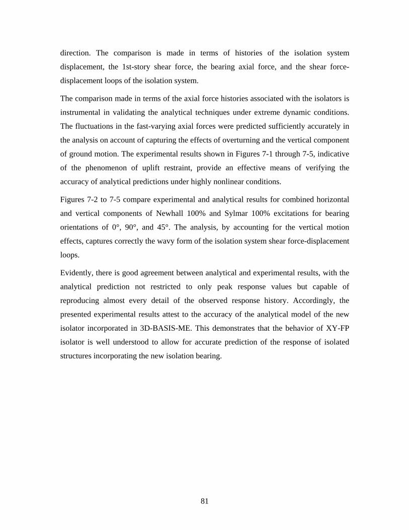
direction. The comparison is made in terms of histories of the isolation system
displacement, the 1st-story shear force, the bearing axial force, and the shear force-
displacement loops of the isolation system.
The comparison made in terms of the axial force histories associated with the isolators is
instrumental in validating the analytical techniques under extreme dynamic conditions.
The fluctuations in the fast-varying axial forces were predicted sufficiently accurately in
the analysis on account of capturing the effects of overturning and the vertical component
of ground motion. The experimental results shown in Figures 7-1 through 7-5, indicative
of the phenomenon of uplift restraint, provide an effective means of verifying the
accuracy of analytical predictions under highly nonlinear conditions.
Figures 7-2 to 7-5 compare experimental and analytical results for combined horizontal
and vertical components of Newhall 100% and Sylmar 100% excitations for bearing
orientations of 0°, 90°, and 45°. The analysis, by accounting for the vertical motion
effects, captures correctly the wavy form of the isolation system shear force-displacement
loops.
Evidently, there is good agreement between analytical and experimental results, with the
analytical prediction not restricted to only peak response values but capable of
reproducing almost every detail of the observed response history. Accordingly, the
presented experimental results attest to the accuracy of the analytical model of the new
isolator incorporated in 3D-BASIS-ME. This demonstrates that the behavior of XY-FP
isolator is well understood to allow for accurate prediction of the response of isolated
structures incorporating the new isolation bearing.
81

0 5 10 15
Axi
al F
orce
(kN
)
-50
0
50
100
150
0 5 10 15
1st-S
tory
She
ar /
Wei
ght
-0.3-0.2-0.10.00.10.20.3
0 5 10 15
Isol
atio
n Sy
stem
D
ispl
acem
ent (
mm
)
-40
-20
0
20
40ExperimentalAnalytical (fmax=0.10)
Test IKBH100A: Kobe N-S 100%, Isolators at θ=0o
Isolation System Displacement (mm)-40 -20 0 20 40
Bas
e Sh
ear /
Wei
ght
-0.3-0.2-0.10.00.10.20.3
Time (sec)0 5 10 15
Axi
al F
orce
(kN
)
-50
0
50
100
150
South Isolator Pair
North Isolator Pair
Weight = 106.5 kN
TENSION
TENSION
Figure 7-1: Comparison of experimental and analytical results for bearing orientation of 0° for 100% Kobe N-S excitation.
82

0 5 10 15
Axi
al F
orce
(kN
)
-50
0
50
100
150
0 5 10 15
1st-S
tory
She
ar /
Wei
ght
-0.3-0.2-0.10.00.10.20.3
0 5 10 15
Isol
atio
n Sy
stem
D
ispl
acem
ent (
mm
)
-60-40-20
0204060
ExperimentalAnalytical (fmax=0.10)
Test IN3B100A: Newhall 360+V 100%, Isolators at θ=0o
Isolation System Displacement (mm)-60 -40 -20 0 20 40 60
Bas
e Sh
ear /
Wei
ght
-0.3-0.2-0.10.00.10.20.3
Time (sec)0 5 10 15
Axi
al F
orce
(kN
)
-50
0
50
100
150
South Isolator Pair
North Isolator Pair
Weight = 106.5 kN
TENSION
TENSION
Figure 7-2: Comparison of experimental and analytical results for bearing orientation of 0° for 100% Newhall 360+vertical excitation.
83

0 5 10 15
Axi
al F
orce
(kN
)
-50
0
50
100
150
0 5 10 15
1st-S
tory
She
ar /
Wei
ght
-0.3-0.2-0.10.00.10.20.3
0 5 10 15
Isol
atio
n Sy
stem
D
ispl
acem
ent (
mm
)
-60-40-20
0204060
ExperimentalAnalytical (fmax=0.10)
Test IN3B100C: Newhall 360+V 100%, Isolators at θ=90o
Isolation System Displacement (mm)-60 -40 -20 0 20 40 60
Bas
e Sh
ear /
Wei
ght
-0.3-0.2-0.10.00.10.20.3
Time (sec)0 5 10 15
Axi
al F
orce
(kN
)
-50
0
50
100
150
South Isolator Pair
North Isolator Pair
Weight = 106.5 kN
TENSION
TENSION
Figure 7-3: Comparison of experimental and analytical results for bearing orientation of 90° for 100% Newhall 360+vertical excitation.
84
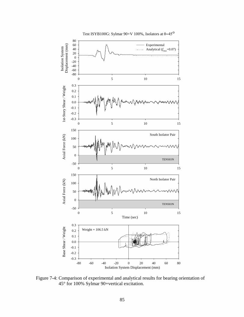
0 5 10 15
Axi
al F
orce
(kN
)
-50
0
50
100
150
0 5 10 15
1st-S
tory
She
ar /
Wei
ght
-0.3-0.2-0.10.00.10.20.3
0 5 10 15
Isol
atio
n Sy
stem
D
ispl
acem
ent (
mm
)
-80-60-40-20
020406080
ExperimentalAnalytical (fmax=0.07)
Test ISYB100G: Sylmar 90+V 100%, Isolators at θ=45o
Isolation System Displacement (mm)-80 -60 -40 -20 0 20 40 60 80
Bas
e Sh
ear /
Wei
ght
-0.3-0.2-0.10.00.10.20.3
Time (sec)0 5 10 15
Axi
al F
orce
(kN
)
-50
0
50
100
150
South Isolator Pair
North Isolator Pair
Weight = 106.5 kN
TENSION
TENSION
Figure 7-4: Comparison of experimental and analytical results for bearing orientation of 45° for 100% Sylmar 90+vertical excitation.
85
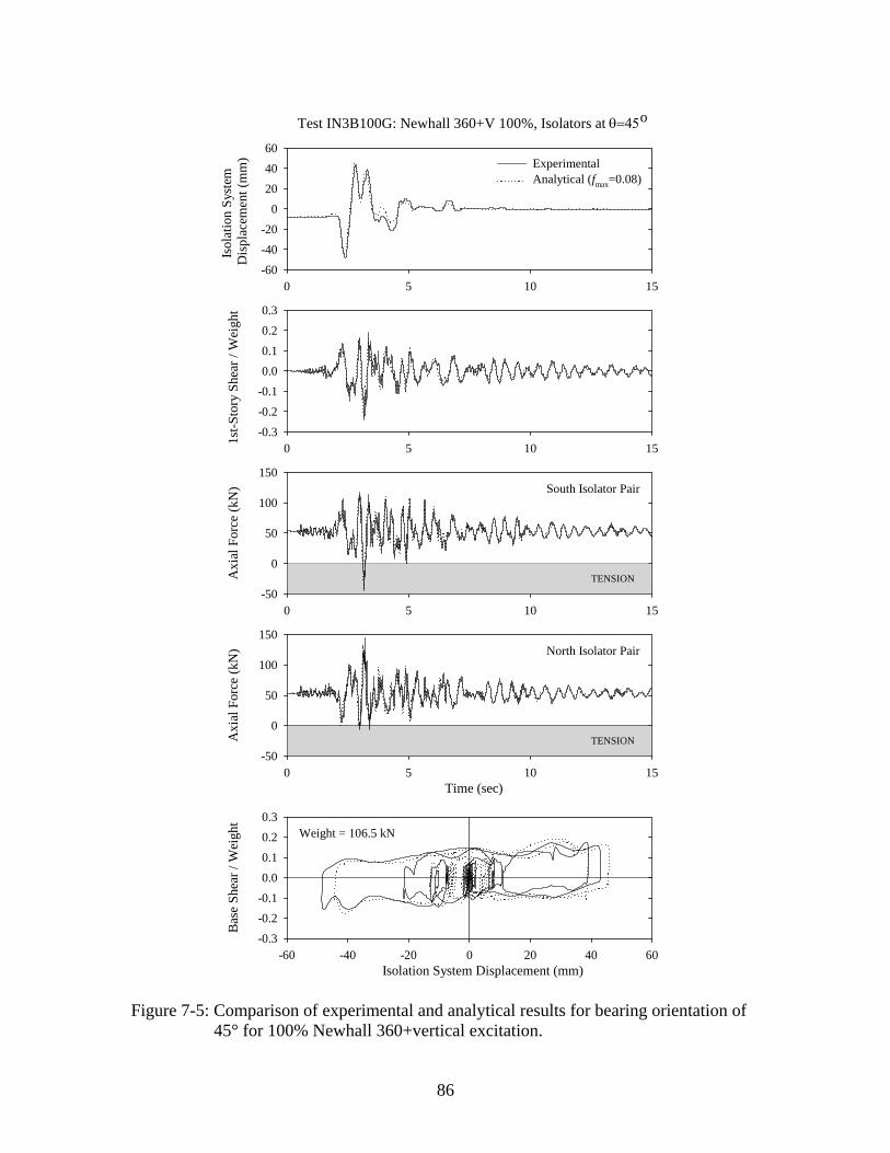
0 5 10 15
Axi
al F
orce
(kN
)
-50
0
50
100
150
0 5 10 15
1st-S
tory
She
ar /
Wei
ght
-0.3-0.2-0.10.00.10.20.3
0 5 10 15
Isol
atio
n Sy
stem
D
ispl
acem
ent (
mm
)
-60-40-20
0204060
ExperimentalAnalytical (fmax=0.08)
Test IN3B100G: Newhall 360+V 100%, Isolators at θ=45o
Isolation System Displacement (mm)-60 -40 -20 0 20 40 60
Bas
e Sh
ear /
Wei
ght
-0.3-0.2-0.10.00.10.20.3
Time (sec)0 5 10 15
Axi
al F
orce
(kN
)
-50
0
50
100
150
South Isolator Pair
North Isolator Pair
Weight = 106.5 kN
TENSION
TENSION
Figure 7-5: Comparison of experimental and analytical results for bearing orientation of 45° for 100% Newhall 360+vertical excitation.
86

SECTION 8
A CASE STUDY
8.1 Introduction
Section 8 presents a case study which involves analysis of a seismically isolated structure
and assessment of the impact of XY-FP bearing on its response. The structure utilized in
the analysis is the new Acropolis Museum in Athens, Greece, currently under
construction, directly at the foot of the Acropolis facing the Parthenon.
In this section, nonlinear response-history analysis of the seismically isolated structure
subjected to bi-directional horizontal seismic excitation was performed using programs
SAP2000 and 3D-BASIS-ME. First, a comparison is made between results from
SAP2000 and 3DBASIS-ME analysis based on an isolation system model consisting
solely of Friction Pendulum (FP) isolators. Then, results from 3D-BASIS-ME analysis of
the model with only FP isolators are compared to results from analysis of the model with
isolators prone to uplift being replaced with XY-FP isolators. The input motions used in
the analysis were arbitrarily scaled so that they cause significant uplift in the FP isolators
or significant tension in the XY-FP isolators, in order to ascertain the impact of use of the
XY-FP isolators in a real structure.
8.2 Description of Seismically Isolated Structure
The new museum of the Acropolis was designed as a four-story building above ground
with up to four underground levels, of which one is for parking and one is for mechanical
equipment (Figure 8-1). In plan the building is quadrilateral with sides measuring about
60 m, 75 m, 40 m, and 100 m (Figure 8-2). The structural system is reinforced concrete
frame mixed with shear walls. The distribution of gravity-carrying elements of the
structure is highly asymmetric due to the existence of archaeological findings that cannot
be moved or disturbed. The total seismic weight of the superstructure is 407 MN. totW =
Figure 8-2 presents a plan view of the isolated structure with the basic dimensions and
bearing locations shown. The most heavily and the least loaded bearings (gravity load
87

Figure 8-1: View of the new Acropolis Museum in Athens, Greece directly at the foot of the Acropolis. (http://www.archpedia.com/Projects-Bernard-Tschumi_01.html)
Figure 8-2: Plan view of isolated structure.
88

consisting of dead load plus half of live load) are identified and the values of the load are
shown on the plan. It may be noted that there is a substantial range of gravity loads on the
bearings.
The structure will be seismically isolated using 94 conventional FP bearings. The
isolators were designed to have a displacement capacity of 250 mm, with radius of
curvature mm, and nominal value of the coefficient of friction under dynamic
conditions equal to 0.04. Upper and lower bound values of the coefficient of friction
when considering uncertainty in properties, aging, temperature, and contamination effects
were determined to be 0.055 and 0.035, respectively.
2235R =
8.3 Analytical Model in SAP2000 and 3D-BASIS-ME
The seismically isolated structure with conventional FP isolators was analyzed in
programs SAP2000 and 3DBASIS-ME. Furthermore, exploiting the newly developed
capability of 3DBASIS-ME to model the behavior of the uplift-restraint XY-FP isolator
(Section 6.3.1), analyses were performed on the seismically isolated structure with
isolators prone to uplift being replaced with XY-FP isolators.
Nonlinear response-history analysis, based on the Fast Nonlinear Analysis (FNA)
method, was performed in SAP2000 (Computers and Structures, 1998), utilizing a three-
dimensional model (Figure 8-3). The model mass, represented as lumped masses at
joints, was distributed at six levels along the height of the model. The properties of the
structure are given in Table 8-1.
Figure 8-4 illustrates the spatial distribution of the 94 seismic isolation bearings. The FP
bearings were modeled in SAP2000 using the NLLINK element Isolator2 property. Each
of these elements was assigned the following properties: radius of sliding surface
m; friction coefficient (fast) 2.235R = max 0.055f = ; friction coefficient (slow)
; rate min 0.03f = 50α = s/m; and an initial stiffness 67007k = kN/m. A damping ratio
of 0.04 was specified for the 18 modes used in the analysis.
The gravity load on the bearings is typically generated in SAP2000 from loads applied to
the superstructure. In this case the gravity load was specified as span force load along the
89
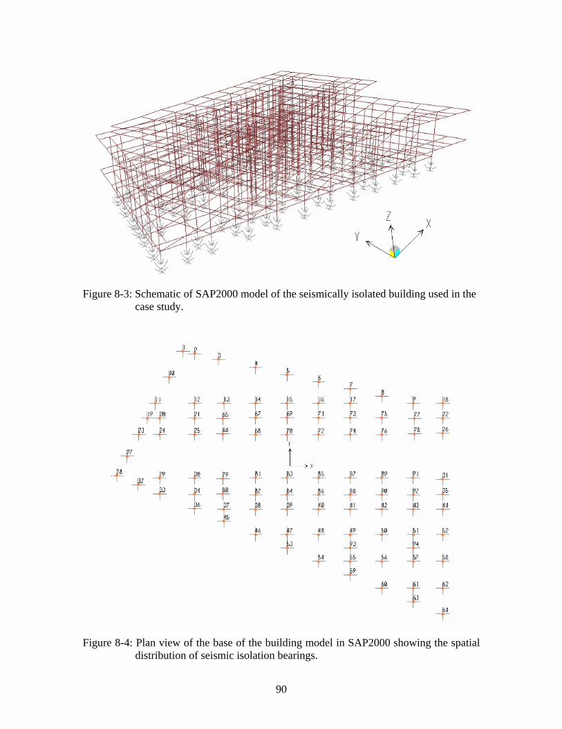
Figure 8-3: Schematic of SAP2000 model of the seismically isolated building used in the case study.
Figure 8-4: Plan view of the base of the building model in SAP2000 showing the spatial distribution of seismic isolation bearings.
90

Table 8-1: Properties of analyzed structure.
Mass Eccentricities Level Height
(m) MX (kN-s2/m)
MY (kN-s2/m)
IZ (kN-s2/m)
X (m)
Y (m)
6 21.4 3512 3512 3125987 2.3 2.4
5 19.4 2208 2208 1063811 2.6 2.8
4 15.3 11049 11049 10627050 2.1 -1.2
3 10.5 6207 6207 4201263 -8.4 6.9
2 5.2 9504 9504 9501796 0.7 -1.7
1 (Base) 0.0 9054 9054 8039340 0.0 0.0
frame members. These forces were applied quasistatically, that is, dynamically over a
long time duration, utilizing a ramp function with a duration of 10 sec (5 sec build-up
time and 5 sec constant unit load) and a large modal damping ratio (= 0.99) to prevent
oscillations.
The dynamic response of the isolated structure was also predicted analytically using
program 3D-BASIS-ME. The superstructure model in 3D-BASIS utilized a three-
dimensional representation. Each floor mass was lumped into a single point mass having
three degrees of freedom (two lateral and one torsional) in the horizontal plane. The
assumed mass distribution is given in Table 8-1. The dynamic characteristics required as
input to 3D-BASIS-ME for the superstructure modeling were obtained using program
SAP2000. A total of 15 modes were used with assumed damping ratio of 0.04. The
periods of free vibration for the first five modes are presented in Table 8-2.
Table 8-2: Periods of free vibration of the fixed-base structure.
Mode Period (sec)
1 0.401
2 0.295
3 0.208
4 0.123
5 0.080
91
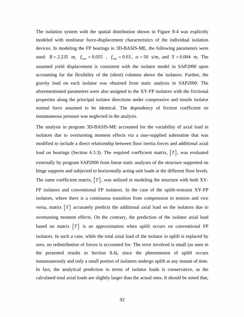
The isolation system with the spatial distribution shown in Figure 8-4 was explicitly
modeled with nonlinear force-displacement characteristics of the individual isolation
devices. In modeling the FP bearings in 3D-BASIS-ME, the following parameters were
used: m, , 2.235R = max 0.055f = min 0.03f = , 50α = s/m, and m. The
assumed yield displacement is consistent with the isolator model in SAP2000 upon
accounting for the flexibility of the (short) columns above the isolators. Further, the
gravity load on each isolator was obtained from static analysis in SAP2000. The
aforementioned parameters were also assigned to the XY-FP isolators with the frictional
properties along the principal isolator directions under compressive and tensile isolator
normal force assumed to be identical. The dependency of friction coefficient on
instantaneous pressure was neglected in the analysis.
0.004=Y
The analysis in program 3D-BASIS-ME accounted for the variability of axial load in
isolators due to overturning moment effects via a user-supplied subroutine that was
modified to include a direct relationship between floor inertia forces and additional axial
load on bearings (Section 6.3.3). The required coefficient matrix, [ ]T , was evaluated
externally by program SAP2000 from linear static analyses of the structure supported on
hinge supports and subjected to horizontally acting unit loads at the different floor levels.
The same coefficient matrix, [ ]T , was utilized in modeling the structure with both XY-
FP isolators and conventional FP isolators. In the case of the uplift-restraint XY-FP
isolators, where there is a continuous transition from compression to tension and vice
versa, matrix [ ]T accurately predicts the additional axial load on the isolators due to
overturning moment effects. On the contrary, the prediction of the isolator axial load
based on matrix [ ]T is an approximation when uplift occurs on conventional FP
isolators. In such a case, while the total axial load of the isolator in uplift is replaced by
zero, no redistribution of forces is accounted for. The error involved is small (as seen in
the presented results in Section 8.4), since the phenomenon of uplift occurs
instantaneously and only a small portion of isolators undergo uplift at any instant of time.
In fact, the analytical prediction in terms of isolator loads is conservative, as the
calculated total axial loads are slightly larger than the actual ones. It should be noted that,
92
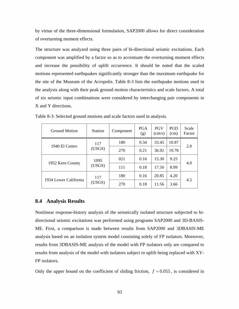
by virtue of the three-dimensional formulation, SAP2000 allows for direct consideration
of overturning moment effects.
The structure was analyzed using three pairs of bi-directional seismic excitations. Each
component was amplified by a factor so as to accentuate the overturning moment effects
and increase the possibility of uplift occurrence. It should be noted that the scaled
motions represented earthquakes significantly stronger than the maximum earthquake for
the site of the Museum of the Acropolis. Table 8-3 lists the earthquake motions used in
the analysis along with their peak ground motion characteristics and scale factors. A total
of six seismic input combinations were considered by interchanging pair components in
X and Y directions.
Table 8-3: Selected ground motions and scale factors used in analysis.
Ground Motion Station Component PGA (g)
PGV (cm/s)
PGD (cm)
Scale Factor
180 0.34 33.45 10.87 1940 El Centro 117
(USGS) 270 0.21 36.92 19.78 2.0
021 0.16 15.30 9.25 1952 Kern County 1095
(USGS) 111 0.18 17.50 8.99 4.0
180 0.16 20.85 4.20 1934 Lower California 117
(USGS) 270 0.18 11.56 3.66 4.5
8.4 Analysis Results
Nonlinear response-history analysis of the seismically isolated structure subjected to bi-
directional seismic excitations was performed using programs SAP2000 and 3D-BASIS-
ME. First, a comparison is made between results from SAP2000 and 3DBASIS-ME
analysis based on an isolation system model consisting solely of FP isolators. Moreover,
results from 3DBASIS-ME analysis of the model with FP isolators only are compared to
results from analysis of the model with isolators subject to uplift being replaced with XY-
FP isolators.
Only the upper bound on the coefficient of sliding friction, 0.055f = , is considered in
93

the analysis, as it yields the maximum forces on the superstructure and hence the most
unfavorable overturning moment effects.
Presented in Appendix D are results generated by programs SAP2000 and 3DBASIS-ME
from analyses of the model with only FP isolators. A representative sample of these
results is depicted in Figures 8-5 through 8-10 in terms of isolation system response,
superstructure response, and individual bearing response in X and Y directions in Lower
California 270-180 450% excitation. The generated results serve the purpose of
demonstrating that programs SAP2000 and 3D-BASIS-ME produce comparable output.
The local frame action and the large overturning forces generated by the strong input
excitations resulted in large variations in the vertical loads on the bearings. These
variations were large enough (compared to the static dead load on the bearings) to reduce
the bearing load to zero and cause local uplift in the bearings (Figures 8-9 and 8-10).
Table 8-4 presents information on the isolators that undergo uplift (with reference to
Figure 8-4) in the six seismic input combinations used in the analysis. Graphical
representation of the number of isolators experienced uplift at each time instant is given
in Figure 8-11. It can be observed that even under such extreme loading conditions only a
small fraction (about 15%) of the isolators undergo uplift at each time instant.
In assessing the impact of the XY-FP bearing on the response of the seismically isolated
structure, results from a 3DBASIS-ME analysis of the model with FP isolators only are
compared to results from analysis of the model with isolators prone to uplift (per Table
8-4) being replaced with XY-FP isolators. Appendix E contains comparison of 3D-
BASIS-ME analysis results of the two models in terms of superstructure response,
isolation system response, and individual bearing response in X and Y directions for the
selected ground motions listed in Table 8-3.
Figures 8-12 through 8-17 depict representative results from the range of analyses
performed for the El Centro 180-270 200% excitation. In particular, Figures 8-12 and 8-
13 provide information on the superstructure response in X and Y directions,
respectively, in terms of histories of total floor acceleration, total floor velocity, and story
drift for the floor/story at which the maximum response occurs, as well as histories of the
normalized first-story shear force. Figures 8-14 and 8-15 present histories of the isolation
94

Tota
l Vel
ocity
(mm
/sec
)
-750
-500
-250
0
250
500
750
Tota
l Acc
eler
atio
n (g
)
-0.3
-0.2
-0.1
0.0
0.1
0.2
0.3
3D-BASISSAP2000
Drif
t (m
m)
-2
-1
0
1
2
X-Direction
Time (sec)
0 5 10 15 20 25 30
Shea
r For
ce /
Wei
ght
-0.2
-0.1
0.0
0.1
0.2
5th Story
3rd Story
3rd Story
1st StoryWeight = 407 MN
Figure 8-5: Comparison of SAP2000 and 3D-BASIS-ME generated results in terms of superstructure response in X direction for the model with 94 FP isolators in scaled (factor 4.5) Lower California 270-180 excitation.
95

Tota
l Vel
ocity
(mm
/sec
)
-750
-500
-250
0
250
500
750
Tota
l Acc
eler
atio
n (g
)
-0.3
-0.2
-0.1
0.0
0.1
0.2
0.3
3D-BASISSAP2000
Drif
t (m
m)
-3
-2
-1
0
1
2
3
Y-Direction
Time (sec)
0 5 10 15 20 25 30
Shea
r For
ce /
Wei
ght
-0.2
-0.1
0.0
0.1
0.2
5th Story
5th Story
2nd Story
1st StoryWeight = 407 MN
Figure 8-6: Comparison of SAP2000 and 3D-BASIS-ME generated results in terms of superstructure response in Y direction for the model with 94 FP isolators in scaled (factor 4.5) Lower California 270-180 excitation.
96

Isol
atio
n Sy
stem
Dis
plac
emen
t (m
m)
-200
-100
0
100
200
3D-BASISSAP2000
Isolation System Displacement (mm)
-200 -100 100 2000
Bas
e Sh
ear (
kN)
-40000
40000
-80000
0
80000
Time (sec)
0 5 10 15 20 25 30
Bas
e Sh
ear (
kN)
-80000
-40000
0
40000
80000
X-Direction
Figure 8-7: Comparison of SAP2000 and 3D-BASIS-ME generated results in terms of isolation system response in X direction for the model with 94 FP isolators in scaled (factor 4.5) Lower California 270-180 excitation.
97

Isol
atio
n Sy
stem
Dis
plac
emen
t (m
m)
-300
-200
-100
0
100
200
300
3D-BASISSAP2000
Isolation System Displacement (mm)
-300 -200 -100 100 200 3000
Bas
e Sh
ear (
kN)
-80000
-40000
40000
80000
0
Time (sec)
0 5 10 15 20 25 30
Bas
e Sh
ear (
kN)
-80000
-40000
0
40000
80000
Y-Direction
Figure 8-8: Comparison of SAP2000 and 3D-BASIS-ME generated results in terms of isolation system response in Y direction for the model with 94 FP isolators in scaled (factor 4.5) Lower California 270-180 excitation.
98

Shea
r For
ce (k
N)
-500
-250
0
250
500
Dis
plac
emen
t (m
m)
-200
-100
0
100
200
3D-BASISSAP2000
Time (sec)0 5 10 15 20 25 30
Axi
al F
orce
(kN
)
-4000
0
4000
8000
X-Direction
Displacement (mm)
-200 -100 100 2000
Shea
r For
ce (k
N)
-250
250
-500
0
500
Bearing 55
Figure 8-9: Comparison of SAP2000 and 3D-BASIS-ME generated results in terms of response of bearing No. 55 in X direction for the model with 94 FP isolators in scaled (factor 4.5) Lower California 270-180 excitation.
99

Shea
r For
ce (k
N)
-750
-500
-250
0
250
500
750
Dis
plac
emen
t (m
m)
-300
-200
-100
0
100
200
300
3D-BASISSAP2000
Time (sec)0 5 10 15 20 25 30
Axi
al F
orce
(kN
)
-4000
0
4000
8000
Y-Direction
Displacement (mm)
-300 -200 -100 100 200 3000
Shea
r For
ce (k
N)
-500
-250
250
500
-750
0
750
Bearing 55
Figure 8-10: Comparison of SAP2000 and 3D-BASIS-ME generated results in terms of response of bearing No. 55 in Y direction for the model with 94 FP isolators in scaled (factor 4.5) Lower California 270-180 excitation.
100
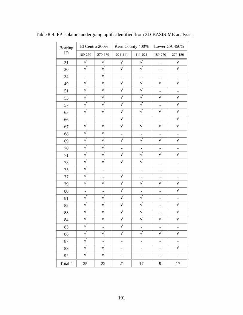
Table 8-4: FP isolators undergoing uplift identified from 3D-BASIS-ME analysis.
El Centro 200% Kern County 400% Lower CA 450% Bearing ID 180-270 270-180 021-111 111-021 180-270 270-180
21 √ √ √ √ - √
30 √ √ √ √ - √
34 - √ - - - - 49 √ √ √ √ √ √
51 √ √ √ √ - - 55 √ √ √ √ √ √
57 √ √ √ √ - √
65 √ √ √ √ √ √
66 - - √ - - √
67 √ √ √ √ √ √
68 √ √ - - - - 69 √ √ √ √ √ √
70 √ √ - - - - 71 √ √ √ √ √ √
73 √ √ √ √ - - 75 √ - - - - - 77 √ - √ - - - 79 √ √ √ √ √ √
80 - - √ - - √
81 √ √ √ √ - - 82 √ √ √ √ - √
83 √ √ √ √ - √
84 √ √ √ √ √ √
85 √ - √ - - - 86 √ √ √ √ √ √
87 √ - - - - - 88 √ √ - - - √
92 √ √ - - - -
Total # 25 22 21 17 9 17
101

system displacement, isolation system shear force, and the associated shear force-
displacement loops in X and Y directions, respectively. Individual bearing results for a
typical bearing that experienced considerable and successive uplift/tension (bearing No.
67) are shown in Figures 8-16 and 8-17 in terms of histories of bearing displacement,
shear force, axial force, and shear force-displacement loops in X and Y directions,
Time (sec)
0 5 10 15 20 25 30N
umbe
r of B
earin
gs in
Upl
ift02468
1012141618
Time (sec)
0 5 10 15 20 25 30
Num
ber o
f Bea
rings
in U
plift
02468
1012141618
El Centro 180-270, 200% El Centro 270-180, 200%
Time (sec)
0 5 10 15 20 25 30
Num
ber o
f Bea
rings
in U
plift
02468
1012141618
Time (sec)
0 5 10 15 20 25 30
Num
ber o
f Bea
rings
in U
plift
02468
1012141618
Kern County 021-111, 400% Kern County 111-021, 400%
Time (sec)
0 5 10 15 20 25 30
Num
ber o
f Bea
rings
in U
plift
02468
1012141618
Time (sec)
0 5 10 15 20 25 30
Num
ber o
f Bea
rings
in U
plift
02468
1012141618
Lower California 180-270, 450% Lower California 270-180, 450%
Figure 8-11: Number of bearings in uplift per time instant.
102

Tota
l Vel
ocity
(mm
/sec
)
-1000
-500
0
500
1000
Tota
l Acc
eler
atio
n (g
)
-0.3
-0.2
-0.1
0.0
0.1
0.2
0.3
94 FP Bearings25 XY-FP and 69 FP Bearings
Drif
t (m
m)
-2
-1
0
1
2
X-Direction
Time (sec)
0 5 10 15 20 25 30
Shea
r For
ce /
Wei
ght
-0.2
-0.1
0.0
0.1
0.2
5th Story
2nd Story
3rd Story
1st StoryWeight = 407 MN
Figure 8-12: Comparison of 3D-BASIS-ME generated results in terms of superstructure response in X direction between the model with 94 FP isolators and the model with 25 XY-FP + 69 FP isolators in scaled (factor 2.0) El Centro 180-270 excitation.
103

Tota
l Vel
ocity
(mm
/sec
)
-1500
-1000
-500
0
500
1000
1500
Tota
l Acc
eler
atio
n (g
)
-0.4-0.3-0.2-0.10.00.10.20.30.4
94 FP Bearings25 XY-FP and 69 FP Bearings
Drif
t (m
m)
-4-3-2-101234
Y-Direction
Time (sec)
0 5 10 15 20 25 30
Shea
r For
ce /
Wei
ght
-0.3
-0.2
-0.1
0.0
0.1
0.2
0.3
5th Story
2nd Story
2nd Story
1st StoryWeight = 407 MN
Figure 8-13: Comparison of 3D-BASIS-ME generated results in terms of superstructure response in Y direction between the model with 94 FP isolators and the model with 25 XY-FP + 69 FP isolators in scaled (factor 2.0) El Centro 180-270 excitation.
104

Isol
atio
n Sy
stem
Dis
plac
emen
t (m
m)
-400
-300
-200
-100
0
100
200
300
400
94 FP Bearings25 XY-FP and 69 FP Bearings
Isolation System Displacement (mm)
-300 -200 -100 100 200 300-400 0 400
Bas
e Sh
ear (
kN)
-50000
50000
-100000
0
100000
Time (sec)
0 5 10 15 20 25 30
Bas
e Sh
ear (
kN)
-100000
-50000
0
50000
100000
X-Direction
Figure 8-14: Comparison of 3D-BASIS-ME generated results in terms of isolation system response in X direction between the model with 94 FP isolators and the model with 25 XY-FP + 69 FP isolators in scaled (factor 2.0) El Centro 180-270 excitation.
105
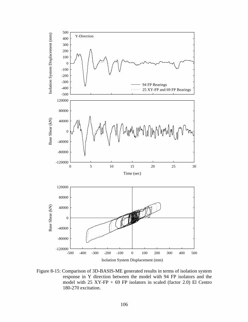
Isol
atio
n Sy
stem
Dis
plac
emen
t (m
m)
-500-400-300-200-100
0100200300400500
94 FP Bearings25 XY-FP and 69 FP Bearings
Isolation System Displacement (mm)
-400 -300 -200 -100 100 200 300 400-500 0 500
Bas
e Sh
ear (
kN)
-80000
-40000
40000
80000
-120000
0
120000
Time (sec)
0 5 10 15 20 25 30
Bas
e Sh
ear (
kN)
-120000
-80000
-40000
0
40000
80000
120000
Y-Direction
Figure 8-15: Comparison of 3D-BASIS-ME generated results in terms of isolation system response in Y direction between the model with 94 FP isolators and the model with 25 XY-FP + 69 FP isolators in scaled (factor 2.0) El Centro 180-270 excitation.
106

Shea
r For
ce (k
N)
-2400
-1600
-800
0
800
1600
2400
Dis
plac
emen
t (m
m)
-400-300-200-100
0100200300400
FP BearingXY-FP Bearing
Time (sec)0 5 10 15 20 25 30
Axi
al F
orce
(kN
)
-10000
-5000
0
5000
10000
15000
X-Direction
Displacement (mm)
-300 -200 -100 100 200 300-400 0 400
Shea
r For
ce (k
N)
-1600
-800
800
1600
-2400
0
2400
Bearing 67
Figure 8-16: Comparison of 3D-BASIS-ME generated results in terms of response of bearing No. 67 in X direction between the model with 94 FP isolators and the model with 25 XY-FP + 69 FP isolators in scaled (factor 2.0) El Centro 180-270 excitation.
107

Shea
r For
ce (k
N)
-2400
-1600
-800
0
800
1600
2400
Dis
plac
emen
t (m
m)
-400-300-200-100
0100200300400
FP Bearing XY-FP Bearing
Time (sec)0 5 10 15 20 25 30
Axi
al F
orce
(kN
)
-10000
-5000
0
5000
10000
15000
Y-Direction
Displacement (mm)
-300 -200 -100 100 200 300-400 0 400
Shea
r For
ce (k
N)
-1600
-800
800
1600
-2400
0
2400
Bearing 67
Figure 8-17: Comparison of 3D-BASIS-ME generated results in terms of response of bearing No. 67 in Y direction between the model with 94 FP isolators and the model with 25 XY-FP + 69 FP isolators in scaled (factor 2.0) El Centro 180-270 excitation.
108

respectively. Of particular interest is the axial force histories associated with the isolator.
Due to strong seismic excitation large overturning moment effects were induced on a
number of bearings, manifested as considerable variation in the axial force histories. For
the isolator in question, the fluctuation in the bearing axial force was large enough, on the
order of 200%, to cause reversal of the bearing axial force from compression to tension.
Nevertheless, the development of tension in individual isolators, and by extension the
increase of isolation system friction force (as discussed in Section 2.3), does not have any
measurable effect on either the isolation system response (Figures 8-14 and 8-15) or the
superstructure response (Figures 8-12 and 8-13). This is attributed to the fact that,
typically, only a small number of the bearings (no more than 15%) are subjected to
tension at any instant of time.
The increase in global friction force due to tension development in XY-FP isolators may
prove significant in rare cases in which adverse conditions prevail in terms of the number
of bearings sustaining tension at any instant of time and the magnitude of the developed
tensile force. A narrow building seismically isolated with only two rows of bearings (e.g.,
the Excel Minami-Koshigaya building in Japan (Sumitomo Construction, 1990)) under
horizontal base excitation in the transverse direction, exemplifies these conditions.
Indeed, by allowing 50% of the uplift-restraint bearings to sustain tension and provided
that the bearing tensile force is significantly larger than the acting weight, the increase in
global friction force can potentially impact the response of structural and non-structural
systems. Nevertheless, even under such adverse conditions, the capability to predict the
response is made available through the newly-developed and verified analytical model of
XY-FP isolator.
109


SECTION 9
SUMMARY AND CONCLUSIONS
This report aimed at extending the scope of seismic isolation by studying a novel sliding
isolation bearing capable of sustaining tension. With its appealing conceptual simplicity
and its proven effectiveness, the new uplift-restraint isolator, termed the XY-FP isolator,
has the potential to facilitate the application of seismic isolation even under the most
extreme of conditions, including but not limited to near-fault strong ground motions and
uplift-prone structural systems.
This study primarily focused on: (i) introducing the concept and establishing the
principles of operation and mathematical model of the new XY-FP isolator; (ii)
developing an understanding of the mechanical behavior of the XY-FP isolator through
testing of a single isolator; (iii) generating experimental results through testing of a
quarter-scale steel-frame model structure on the earthquake simulator at the University at
Buffalo to validate the effectiveness of these isolators in preventing uplift; (iv) modifying
the computer program 3D-BASIS-ME to include an element representative of the
mechanical behavior of the new XY-FP isolator; and (v) assessing the validity and
accuracy of analytical methods to predict the behavior of such systems.
Even though a number of uplift prevention systems in seismic isolation have been
proposed (and some have been implemented), their potential has been hindered by
limitations stemmed from their intrinsic complexity, unpredictability, and/or deficiency
to provide effective uplift prevention. Moreover, a number of such systems have not been
tested and their impact on the behavior of the isolation system has not been assessed.
Accordingly, a need evolved to develop acceptable isolators with tension (or uplift
restraint) capability and to better understand the phenomena of uplift or tension of
isolators and their impact on the performance of structural and non-structural systems.
Studied in this report is an effective uplift-restraint isolation bearing synthesized by two
opposing concave stainless steel-faced beams to form a bi-directional (XY) motion
mechanism. The salient features that distinguish the XY-FP isolator from the
conventional Friction Pendulum (FP) isolator include: (i) effective uplift prevention
111

regardless of the state of displacement in the bearing; (ii) decoupling of the bi-directional
horizontal motion along two orthogonal directions; and (iii) capability of providing
distinct stiffness and energy dissipation along the principal directions of the bearing.
Additional benefits can be derived from the unique morphology of the new bearing. In
particular, by encompassing much less structural material, the isolator offers a lighter and
more economical alternative to the standard FP bearing, and by extension a higher
manufacturing quality. Moreover, it provides an architecturally flexible solution in terms
of integration into a structural system for cases where space considerations are important.
A displacement-control testing program on a single XY-FP isolator was conducted to
expand our understanding of its mechanical behavior and to extract various frictional
characteristics of interest, under compressive and tensile normal load. The testing
included a range of isolator orientation angles, normal loads (compressive and tensile),
and peak sliding velocities. The generated results reveal the dependency of the coefficient
of friction both on the apparent pressure and on the velocity of sliding. The studies also
verified that, given the frictional properties of the two isolator component beams, the
equivalent coefficient of friction can be calculated in any direction.
The testing program on the earthquake simulator at the University at Buffalo involved a
five-story base-isolated model structure and a number of recorded horizontal and vertical
ground motions with a wide range of both frequency content and amplitude. The isolation
system, comprised of four uplift-prevention XY-FP isolators, was installed beneath a
base and rotated for testing in different directions (0-, 45-, and 90-degree angle). This
series of tests represent the only available experimental data on XY-FP isolators.
In this testing configuration, the bearing pressure was very small, and modest changes in
axial load produced a large variation in the frictional properties of the isolation system.
The small weight of the model structure and the four-bearing condition are “extreme” for
building structures; much smaller variations in frictional response are to be expected in
real-life applications.
Of particular interest are the results pertaining to the axial force histories associated with
the isolators. Due to the slenderness of the structure (height to width aspect ratio
approximately 4.5), large overturning moment effects were induced on the bearings under
112

strong base excitation. This was manifested as considerable variation in axial force, on
the order of 100%, which in some cases proved large enough to cause reversal of the
bearing axial force from compression to tension.
Results from a number of tests conducted with combined horizontal and vertical
excitations provided evidence of the effect of the vertical component of ground motion
on the response of the isolated structure. The results demonstrated that the vertical ground
motion component had a minor effect on the isolation system displacement, yet a non-
negligible effect on the isolation system force response, a deviation on the order of 15%,
reflected primarily in the wavy form of the isolation system hysteresis loop. The effect of
the vertical component of ground motion was pronounced in the local response of the
isolators. In effect, the vertical ground acceleration modified significantly the axial load
on the bearings, causing, in some cases, tension to develop in the bearing.
The range of tests performed on the model structure demonstrated the validity of the
concept and provided evidence for the effectiveness of the XY-FP isolator in uplift
prevention. Clearly, the new isolator is capable of developing tension, thereby providing
uplift restraint. In addition, the experimental response formed the basis for comparison
with and validation of the analytical predictions.
A comprehensive mathematical model capable of accommodating the mechanical
behavior of the XY-FP isolator was developed and implemented in program 3D-BASIS-
ME. In doing so, a new hysteretic element representing the XY-FP isolator was
incorporated in 3D-BASIS-ME. The element is synthesized by two independent uniaxial
hysteretic elements allowing different frictional interface properties along the principal
isolator directions. It should be emphasized that, contrary to the element representing the
conventional FP isolator, the new element is capable of developing tension and therefore
providing uplift restraint. Moreover, different frictional interface properties can be
assumed under compressive and tensile isolator normal force. This enhancement
augments the potential of 3D-BASIS-ME by providing a versatile tool for analysis of
seismically isolated structures with XY-FP isolators.
The dynamic response of the five-story seismically isolated model was predicted
analytically using 3D-BASIS-ME. The analysis accounted for the variability of the
113

isolator axial load due to the vertical component of ground motion and the overturning
moment effects, the dependency of friction coefficient on velocity, different isolator
orientations, and the initial non-zero displacement of the isolators.
The validity of the 3D-BASIS-ME analytical model with reference to the newly
introduced element representing the XY-FP isolator was investigated by comparison of
analytical predictions with experimental results. The maximum deviation between peak
experimental and analytical response quantities was on the order of 15% or less. The
good agreement attests to the accuracy of the analytical model, evident even under
extreme dynamic conditions entailing tension in the isolators. This demonstrates that the
behavior of the XY-FP isolator is sufficiently well understood to allow for accurate
prediction of the response of isolated structures incorporating the proposed isolation
devices.
A case study involved analysis of the new Acropolis Museum in Athens, Greece and
assessment of the impact of XY-FP isolator on its response. Nonlinear response-history
analysis of the seismically isolated structure subjected to bi-directional horizontal seismic
excitation was performed using programs SAP2000 and 3D-BASIS-ME. The seismically
isolated structure with solely conventional FP isolators was analyzed in program
3DBASIS-ME to identify the isolators that undergo uplift. Additional analysis of the
structure with an analogous isolation system model was performed in program SAP2000
as a means for comparison. The generated results demonstrate that programs SAP2000
and 3D-BASIS-ME produce comparable output.
In addition, 3D-BASIS-ME analysis was performed on the seismically isolated structure
with isolators prone to uplift being replaced with XY-FP isolators. These results
demonstrate that tension in individual XY-FP isolators, and by extension the increase of
isolation system friction force, did not have any appreciable effect on either the total
isolation system response or the superstructure response. This is attributed to the fact that,
typically, only a small number of the bearings (no more than 15%) are subjected to
tension at any instant of time.
The increase in global friction force due to tension development in XY-FP isolators may
prove significant in rare cases in which adverse conditions prevail in terms of the number
114

of bearings sustaining tension at any instant of time and the magnitude of the developed
tensile force. A narrow building seismically isolated with only two rows of bearings
under horizontal base excitation in the transverse direction, exemplifies these conditions.
Indeed, by allowing 50% of the uplift-restraint bearings to sustain tension, and provided
that the bearing tensile force is significantly larger than the acting weight, the increase in
global friction force can potentially impact the response of structural and non-structural
systems. Nevertheless, even under such adverse conditions, the capability to predict the
response is made available through the newly developed and verified analytical model of
XY-FP isolator.
115

SECTION 10
REFERENCES
Al-Hussaini, T.M., Zayas, V.A., and Constantinou, M.C. (1994), “Seismic Isolation of
Multi-Story Frame Structures Using Spherical Sliding Isolation System,” Report No.
NCEER-94-0007, National Center for Earthquake Engineering Research, State University
of New York, Buffalo, NY.
Bracci, J.M., Reinhorn, A.M., and Mander, J.B. (1992), “Seismic Resistance of
Reinforced Concrete Frame Structures Designed Only for Gravity Loads: Part I - Design
and Properties of a One-Third Scale Model Structure,” Report No. NCEER-92-0027,
National Center for Earthquake Engineering Research, State University of New York,
Buffalo, NY.
Chang, K.C., Lai, M.L., Soong, T.T., Hao, D.S., and Yeh, Y.C. (1993), “Seismic
Behavior and Design Guidelines for Steel Frame Structures with Added Viscoelastic
Dampers,” Report No. NCEER-93-0009, National Center for Earthquake Engineering
Research, State University of New York, Buffalo, NY.
Computers and Structures Inc. (1998), “SAP2000: Integrated Finite Element Analysis
and Design of Structures,” Version 7.5, Berkeley, CA.
Constantinou, M.C. (1998), “Application of Seismic Isolation Systems in Greece,”
Proceedings of ’98 Structural Engineers World Congress, Paper T175-3, San Francisco,
CA.
Constantinou, M.C., Mokha, A., and Reinhorn, A.M. (1990), “Teflon Bearings in Base
Isolation II: Modeling,” Journal of Structural Engineering, ASCE, 116(2), 455-474.
Constantinou, M.C., Tsopelas, P.C., Kasalanati, A., and Wolff, E. (1999), “Property
Modification Factors for Seismic Isolation Bearings,” Report No. MCEER-990012,
Multidisciplinary Center for Earthquake Engineering Research, State University of New
York, Buffalo, NY.
117

Constantinou, M.C., Tsopelas, P., Kim, Y-S., and Okamoto, S. (1993), “NCEER-TAISEI
Corporation Research Program on Sliding Seismic Isolation Systems for Bridges-
Experimental and Analytical Study of Friction Pendulum System (FPS),” Report No.
NCEER 93-0020, National Center for Earthquake Engineering Research, State University
of New York, Buffalo, NY.
Goodman, T.P. (1963), “Analysis of Two Dimensional Motion Resisted by Coulomb
Friction,” Journal of Engineering for Industry, 85, 17-26.
Griffith, M.C., Kelly, J.M., Coveney, V.A., and Koh, C.G. (1988a), “Experimental
Evaluation of Seismic Isolation of Medium-Rise Structures Subject to Uplift,” Report No.
UCB/EERC-88/02, Earthquake Engineering Research Center, University of California,
Berkeley, CA.
Griffith, M.C., Aiken, I.D., and Kelly, J.M. (1988b), “Experimental Evaluation of
Seismic Isolation of a 9-Story Braced Steel Frame Subject to Uplift,” Report No.
UCB/EERC-88/05, Earthquake Engineering Research Center, University of California,
Berkeley, CA.
Griffith, M.C., Aiken, I.D., and Kelly, J.M. (1990), “Displacement Control and Uplift
Restraint for Base-Isolated Structures,” Journal of Structural Engineering, ASCE 116(4),
1135-1148.
Honeck, W., Walters, M., Sattary, V., and Rodler, P. (1993), “Seismic Isolation of the
Oakland City Hall,” Proceedings of ATC-17-1 Seminar on Seismic Isolation, Passive
Energy Dissipation, and Active Control, San Francisco, CA, March 11-12, 1993, Vol. I,
221-232.
Kasalanati, A. and Constantinou, M.C. (1999), “Experimental Study of Bridge
Elastomeric and Other Isolation and Energy Dissipation Systems with Emphasis on
Uplift Prevention and High Velocity Near-Source Seismic Excitation,” Report No.
MCEER-99-0004, Multidisciplinary Center for Earthquake Engineering Research, State
University of New York, Buffalo, NY.
118

Kelly, J.M., Griffith, M.C., and Aiken, I.D. (1987), “A Displacement Control and Uplift
Restraint Device for Base Isolated Structures,” Report No. UCB/EERC-87/03,
Earthquake Engineering Research Center, University of California, Berkeley, CA.
Logiadis, I.S.E. (1996), “Application of Vertical Unbonded Tensioned Prestressed
Tendons in the Seismic Isolation of Structures,” Dissertation, Technische Universitat
Munchen (in German).
Mokha, A., Constantinou, M.C., and Reinhorn, A.M. (1988), “Teflon Bearings in
Aseismic Base Isolation: Experimental Studies and Mathematical Modeling,” Report
NCEER-88-0038, National Center for Earthquake Engineering Research, State University
of New York, Buffalo, NY.
Mokha, A.S., Constantinou, M.C., and Reinhorn, A.M. (1990), “Experimental Study and
Analytical Prediction of Earthquake Response of a Sliding Isolation System with
Spherical Surface,” Report NCEER-90-0020, National Center for Earthquake
Engineering Research, State University of New York, Buffalo, NY.
Mosqueda, G., Whittaker, A.S., and Fenves, G.L. (2004), “Characterization and
Modeling of Friction Pendulum Bearings Subjected to Multiple Components of
Excitation,” Journal of Structural Engineering, ASCE, 130(3), 433-442.
Mostaghel, N. and Khodaverdian, M. (1987), “Dynamics of Resilient-Friction Base
Isolator (R-FBI),” Earthquake Engineering and Structural Dynamics, 15(3), 379-390.
Naeim, F. and Kelly, J.M. (1999), Design of Seismic Isolated Structures – From Theory
to Practice, John Wiley & Sons Inc., NY.
Nagarajaiah, S., Reinhorn, A.M., and Constantinou, M.C. (1989), “Nonlinear Dynamic
Analysis of Three Dimensional Base Isolated Structures (3D-BASIS),” Report No.
NCEER-89-0019, National Center for Earthquake Engineering Research, State University
of New York, Buffalo, NY.
Nagarajaiah, S., Reinhorn, A.M., and Constantinou, M.C. (1992), “Experimental Study of
Sliding Isolated Structures with Uplift Restraint,” Journal of Structural Engineering,
119

ASCE, 118(6), 1666–1682.
Nagarajaiah, S., Reinhorn, A.M., and Constantinou, M.C. (1991a), “Nonlinear Dynamic
Analysis of Three Dimensional Base Isolated Structures,” Journal of Structural
Engineering, ASCE, 117(7), 2035-2054.
Nagarajaiah, S., Reinhorn, A.M., and Constantinou, M.C. (1991b), “Nonlinear Dynamic
Analysis of Three Dimensional Base Isolated Structures, Part II,” Report No. NCEER-91-
0005, National Center for Earthquake Engineering Research, State University of New
York, Buffalo, NY.
Nagarajaiah, S., Li, C., Reinhorn, A.M., and Constantinou, M.C. (1993), “3D-BASIS-
TABS: Computer Program for Nonlinear Dynamic Analysis of SD-Base-Isolated
Structures,” Report No. NCEER-93-0011, National Center for Earthquake Engineering
Research, State University of New York, Buffalo, NY.
Ozdemir, H. (1976), “Nonlinear Transient Dynamic Analysis of Yielding Structures,”
Ph.D. Thesis, Department of Civil Engineering, University of California, at Berkeley,
CA.
Park, Y.J., Wen, Y.K., and Ang, A.H.S. (1986), “Random Vibration of Hysteretic
Systems under Bidirectional Ground Motions,” Earthquake Engineering and Structural
Dynamics, 14(4), 543-557.
Ramirez, O.M., Constantinou, M.C., Kircher, C.A., Whittaker, A.S., Johnson, M.W., and
Gomez, J.D. (2001), “Development and Evaluation of Simplified Procedures for Analysis
and Design of Buildings with Passive Energy Dissipation Systems,” Report No. MCEER-
00-0010, Multidisciplinary Center for Earthquake Engineering Research, State University
of New York, Buffalo, NY.
Roussis, P.C. (2004), “Experimental and Analytical Studies of Structures Seismically
Isolated with an Uplift-Restraint Isolation System,” Ph.D. Dissertation, Department of
Civil, Structural and Environmental Engineering, University at Buffalo, State University
of New York, Buffalo, NY.
120

Roussis, P.C., Constantinou, M.C., Erdik, M., Durukal, E., and Dicleli, M. (2003),
“Assessment of Performance of Seismic Isolation System of Bolu Viaduct,” Journal of
Bridge Engineering, ASCE, 8(4), 182-190.
Roussis, P.C., Constantinou, M.C., Erdik, M., Durukal, E., and Dicleli, M. (2002),
“Assessment of Performance of Bolu Viaduct in the 1999 Duzce Earthquake in Turkey,”
Report No. MCEER-02-0001, Multidisciplinary Center for Earthquake Engineering
Research, Buffalo, NY.
Skinner, R.I., Robinson, W.H., and McVerry, G.H. (1993), An Introduction to Seismic
Isolation, John Wiley & Sons Inc., NY.
Soong, T.T. and Constantinou, M.C. (1994), Passive and Active Structural Vibration
Control in Civil Engineering, Springer-Verlag, Wien.
Su, L., Ahmadi, G., and Tadjbakhsh, I.G. (1987), “A Comparative Study of Base
Isolation Systems,” Report No. MIE-150, Clarkson University, Potsdam, NY.
Sumitomo Construction (1990), “Base-Isolated Buildings by Sumitomo Construction,”
Report by Sumitomo Construction Co.Ltd., Tokyo, Japan.
Tsopelas, P.C., Nagarajaiah, S., Constantinou, M.C., and Reinhorn, A.M. (1991), “3D-
BASIS-M: Nonlinear Dynamic Analysis of Multiple Building Base Isolated Structures,”
Report No. NCEER91-0014, National Center for Earthquake Engineering Research, State
University of New York, Buffalo, NY.
Tsopelas, P.C., Constantinou, M.C., and Reinhorn, A.M. (1994), “3D-BASIS-ME:
Computer Program for Nonlinear Dynamic Analysis of Seismically Isolated Single and
Multiple Structures and Liquid Storage Tanks,” Report No. MCEER-94-0010,
Multidisciplinary Center for Earthquake Engineering Research, State University of New
York, Buffalo, NY.
Wen, Y.K. (1976), “Method of Random Vibration of Hysteretic Systems,” Journal of
Engineering Mechanics Division, ASCE, 102(2), 249-263.
121

Younis, C., Tadjbakhsh, I.G., and Saibel, E.A. (1983), “Analysis of General Plane
Motion with Coulomb Friction,” Wear, 91, 319-331.
Zayas, V., Low, S.S., and Mahin, S.A. (1987), “The FPS Earthquake Resisting System,
Experimental Report,” Report No. UBC/EERC-87/01, Earthquake Engineering Research
Center, University of California, Berkeley, CA.
122
Formerly the National Center for Earthquake Engineering Research
123
Multidisciplinary Center for Earthquake Engineering Research List of Technical Reports
The Multidisciplinary Center for Earthquake Engineering Research (MCEER) publishes technical reports on a variety of subjects related to earthquake engineering written by authors funded through MCEER. These reports are available from both MCEER Publications and the National Technical Information Service (NTIS). Requests for reports should be directed to MCEER Publications, Multidisciplinary Center for Earthquake Engineering Research, State University of New York at Buffalo, Red Jacket Quadrangle, Buffalo, New York 14261. Reports can also be requested through NTIS, 5285 Port Royal Road, Springfield, Virginia 22161. NTIS accession numbers are shown in parenthesis, if available. NCEER-87-0001 "First-Year Program in Research, Education and Technology Transfer," 3/5/87, (PB88-134275, A04, MF-
A01). NCEER-87-0002 "Experimental Evaluation of Instantaneous Optimal Algorithms for Structural Control," by R.C. Lin, T.T.
Soong and A.M. Reinhorn, 4/20/87, (PB88-134341, A04, MF-A01). NCEER-87-0003 "Experimentation Using the Earthquake Simulation Facilities at University at Buffalo," by A.M. Reinhorn
and R.L. Ketter, to be published. NCEER-87-0004 "The System Characteristics and Performance of a Shaking Table," by J.S. Hwang, K.C. Chang and G.C.
Lee, 6/1/87, (PB88-134259, A03, MF-A01). This report is available only through NTIS (see address given above).
NCEER-87-0005 "A Finite Element Formulation for Nonlinear Viscoplastic Material Using a Q Model," by O. Gyebi and G.
Dasgupta, 11/2/87, (PB88-213764, A08, MF-A01). NCEER-87-0006 "Symbolic Manipulation Program (SMP) - Algebraic Codes for Two and Three Dimensional Finite Element
Formulations," by X. Lee and G. Dasgupta, 11/9/87, (PB88-218522, A05, MF-A01). NCEER-87-0007 "Instantaneous Optimal Control Laws for Tall Buildings Under Seismic Excitations," by J.N. Yang, A.
Akbarpour and P. Ghaemmaghami, 6/10/87, (PB88-134333, A06, MF-A01). This report is only available through NTIS (see address given above).
NCEER-87-0008 "IDARC: Inelastic Damage Analysis of Reinforced Concrete Frame - Shear-Wall Structures," by Y.J. Park,
A.M. Reinhorn and S.K. Kunnath, 7/20/87, (PB88-134325, A09, MF-A01). This report is only available through NTIS (see address given above).
NCEER-87-0009 "Liquefaction Potential for New York State: A Preliminary Report on Sites in Manhattan and Buffalo," by
M. Budhu, V. Vijayakumar, R.F. Giese and L. Baumgras, 8/31/87, (PB88-163704, A03, MF-A01). This report is available only through NTIS (see address given above).
NCEER-87-0010 "Vertical and Torsional Vibration of Foundations in Inhomogeneous Media," by A.S. Veletsos and K.W.
Dotson, 6/1/87, (PB88-134291, A03, MF-A01). This report is only available through NTIS (see address given above).
NCEER-87-0011 "Seismic Probabilistic Risk Assessment and Seismic Margins Studies for Nuclear Power Plants," by Howard
H.M. Hwang, 6/15/87, (PB88-134267, A03, MF-A01). This report is only available through NTIS (see address given above).
NCEER-87-0012 "Parametric Studies of Frequency Response of Secondary Systems Under Ground-Acceleration Excitations,"
by Y. Yong and Y.K. Lin, 6/10/87, (PB88-134309, A03, MF-A01). This report is only available through NTIS (see address given above).
NCEER-87-0013 "Frequency Response of Secondary Systems Under Seismic Excitation," by J.A. HoLung, J. Cai and Y.K.
Lin, 7/31/87, (PB88-134317, A05, MF-A01). This report is only available through NTIS (see address given above).
NCEER-87-0014 "Modelling Earthquake Ground Motions in Seismically Active Regions Using Parametric Time Series
Methods," by G.W. Ellis and A.S. Cakmak, 8/25/87, (PB88-134283, A08, MF-A01). This report is only available through NTIS (see address given above).
Formerly the National Center for Earthquake Engineering Research
124
NCEER-87-0015 "Detection and Assessment of Seismic Structural Damage," by E. DiPasquale and A.S. Cakmak, 8/25/87,
(PB88-163712, A05, MF-A01). This report is only available through NTIS (see address given above). NCEER-87-0016 "Pipeline Experiment at Parkfield, California," by J. Isenberg and E. Richardson, 9/15/87, (PB88-163720,
A03, MF-A01). This report is available only through NTIS (see address given above). NCEER-87-0017 "Digital Simulation of Seismic Ground Motion," by M. Shinozuka, G. Deodatis and T. Harada, 8/31/87,
(PB88-155197, A04, MF-A01). This report is available only through NTIS (see address given above). NCEER-87-0018 "Practical Considerations for Structural Control: System Uncertainty, System Time Delay and Truncation of
Small Control Forces," J.N. Yang and A. Akbarpour, 8/10/87, (PB88-163738, A08, MF-A01). This report is only available through NTIS (see address given above).
NCEER-87-0019 "Modal Analysis of Nonclassically Damped Structural Systems Using Canonical Transformation," by J.N.
Yang, S. Sarkani and F.X. Long, 9/27/87, (PB88-187851, A04, MF-A01). NCEER-87-0020 "A Nonstationary Solution in Random Vibration Theory," by J.R. Red-Horse and P.D. Spanos, 11/3/87,
(PB88-163746, A03, MF-A01). NCEER-87-0021 "Horizontal Impedances for Radially Inhomogeneous Viscoelastic Soil Layers," by A.S. Veletsos and K.W.
Dotson, 10/15/87, (PB88-150859, A04, MF-A01). NCEER-87-0022 "Seismic Damage Assessment of Reinforced Concrete Members," by Y.S. Chung, C. Meyer and M.
Shinozuka, 10/9/87, (PB88-150867, A05, MF-A01). This report is available only through NTIS (see address given above).
NCEER-87-0023 "Active Structural Control in Civil Engineering," by T.T. Soong, 11/11/87, (PB88-187778, A03, MF-A01). NCEER-87-0024 "Vertical and Torsional Impedances for Radially Inhomogeneous Viscoelastic Soil Layers," by K.W. Dotson
and A.S. Veletsos, 12/87, (PB88-187786, A03, MF-A01). NCEER-87-0025 "Proceedings from the Symposium on Seismic Hazards, Ground Motions, Soil-Liquefaction and Engineering
Practice in Eastern North America," October 20-22, 1987, edited by K.H. Jacob, 12/87, (PB88-188115, A23, MF-A01). This report is available only through NTIS (see address given above).
NCEER-87-0026 "Report on the Whittier-Narrows, California, Earthquake of October 1, 1987," by J. Pantelic and A.
Reinhorn, 11/87, (PB88-187752, A03, MF-A01). This report is available only through NTIS (see address given above).
NCEER-87-0027 "Design of a Modular Program for Transient Nonlinear Analysis of Large 3-D Building Structures," by S.
Srivastav and J.F. Abel, 12/30/87, (PB88-187950, A05, MF-A01). This report is only available through NTIS (see address given above).
NCEER-87-0028 "Second-Year Program in Research, Education and Technology Transfer," 3/8/88, (PB88-219480, A04, MF-
A01). NCEER-88-0001 "Workshop on Seismic Computer Analysis and Design of Buildings With Interactive Graphics," by W.
McGuire, J.F. Abel and C.H. Conley, 1/18/88, (PB88-187760, A03, MF-A01). This report is only available through NTIS (see address given above).
NCEER-88-0002 "Optimal Control of Nonlinear Flexible Structures," by J.N. Yang, F.X. Long and D. Wong, 1/22/88, (PB88-
213772, A06, MF-A01). NCEER-88-0003 "Substructuring Techniques in the Time Domain for Primary-Secondary Structural Systems," by G.D.
Manolis and G. Juhn, 2/10/88, (PB88-213780, A04, MF-A01). NCEER-88-0004 "Iterative Seismic Analysis of Primary-Secondary Systems," by A. Singhal, L.D. Lutes and P.D. Spanos,
2/23/88, (PB88-213798, A04, MF-A01).
Formerly the National Center for Earthquake Engineering Research
125
NCEER-88-0005 "Stochastic Finite Element Expansion for Random Media," by P.D. Spanos and R. Ghanem, 3/14/88, (PB88-213806, A03, MF-A01).
NCEER-88-0006 "Combining Structural Optimization and Structural Control," by F.Y. Cheng and C.P. Pantelides, 1/10/88,
(PB88-213814, A05, MF-A01). NCEER-88-0007 "Seismic Performance Assessment of Code-Designed Structures," by H.H-M. Hwang, J-W. Jaw and H-J.
Shau, 3/20/88, (PB88-219423, A04, MF-A01). This report is only available through NTIS (see address given above).
NCEER-88-0008 "Reliability Analysis of Code-Designed Structures Under Natural Hazards," by H.H-M. Hwang, H. Ushiba
and M. Shinozuka, 2/29/88, (PB88-229471, A07, MF-A01). This report is only available through NTIS (see address given above).
NCEER-88-0009 "Seismic Fragility Analysis of Shear Wall Structures," by J-W Jaw and H.H-M. Hwang, 4/30/88, (PB89-
102867, A04, MF-A01). NCEER-88-0010 "Base Isolation of a Multi-Story Building Under a Harmonic Ground Motion - A Comparison of
Performances of Various Systems," by F-G Fan, G. Ahmadi and I.G. Tadjbakhsh, 5/18/88, (PB89-122238, A06, MF-A01). This report is only available through NTIS (see address given above).
NCEER-88-0011 "Seismic Floor Response Spectra for a Combined System by Green's Functions," by F.M. Lavelle, L.A.
Bergman and P.D. Spanos, 5/1/88, (PB89-102875, A03, MF-A01). NCEER-88-0012 "A New Solution Technique for Randomly Excited Hysteretic Structures," by G.Q. Cai and Y.K. Lin,
5/16/88, (PB89-102883, A03, MF-A01). NCEER-88-0013 "A Study of Radiation Damping and Soil-Structure Interaction Effects in the Centrifuge," by K. Weissman,
supervised by J.H. Prevost, 5/24/88, (PB89-144703, A06, MF-A01). NCEER-88-0014 "Parameter Identification and Implementation of a Kinematic Plasticity Model for Frictional Soils," by J.H.
Prevost and D.V. Griffiths, to be published. NCEER-88-0015 "Two- and Three- Dimensional Dynamic Finite Element Analyses of the Long Valley Dam," by D.V.
Griffiths and J.H. Prevost, 6/17/88, (PB89-144711, A04, MF-A01). NCEER-88-0016 "Damage Assessment of Reinforced Concrete Structures in Eastern United States," by A.M. Reinhorn, M.J.
Seidel, S.K. Kunnath and Y.J. Park, 6/15/88, (PB89-122220, A04, MF-A01). This report is only available through NTIS (see address given above).
NCEER-88-0017 "Dynamic Compliance of Vertically Loaded Strip Foundations in Multilayered Viscoelastic Soils," by S.
Ahmad and A.S.M. Israil, 6/17/88, (PB89-102891, A04, MF-A01). NCEER-88-0018 "An Experimental Study of Seismic Structural Response With Added Viscoelastic Dampers," by R.C. Lin, Z.
Liang, T.T. Soong and R.H. Zhang, 6/30/88, (PB89-122212, A05, MF-A01). This report is available only through NTIS (see address given above).
NCEER-88-0019 "Experimental Investigation of Primary - Secondary System Interaction," by G.D. Manolis, G. Juhn and
A.M. Reinhorn, 5/27/88, (PB89-122204, A04, MF-A01). NCEER-88-0020 "A Response Spectrum Approach For Analysis of Nonclassically Damped Structures," by J.N. Yang, S.
Sarkani and F.X. Long, 4/22/88, (PB89-102909, A04, MF-A01). NCEER-88-0021 "Seismic Interaction of Structures and Soils: Stochastic Approach," by A.S. Veletsos and A.M. Prasad,
7/21/88, (PB89-122196, A04, MF-A01). This report is only available through NTIS (see address given above).
NCEER-88-0022 "Identification of the Serviceability Limit State and Detection of Seismic Structural Damage," by E.
DiPasquale and A.S. Cakmak, 6/15/88, (PB89-122188, A05, MF-A01). This report is available only through NTIS (see address given above).

Formerly the National Center for Earthquake Engineering Research
126
NCEER-88-0023 "Multi-Hazard Risk Analysis: Case of a Simple Offshore Structure," by B.K. Bhartia and E.H. Vanmarcke, 7/21/88, (PB89-145213, A05, MF-A01).
NCEER-88-0024 "Automated Seismic Design of Reinforced Concrete Buildings," by Y.S. Chung, C. Meyer and M.
Shinozuka, 7/5/88, (PB89-122170, A06, MF-A01). This report is available only through NTIS (see address given above).
NCEER-88-0025 "Experimental Study of Active Control of MDOF Structures Under Seismic Excitations," by L.L. Chung,
R.C. Lin, T.T. Soong and A.M. Reinhorn, 7/10/88, (PB89-122600, A04, MF-A01). NCEER-88-0026 "Earthquake Simulation Tests of a Low-Rise Metal Structure," by J.S. Hwang, K.C. Chang, G.C. Lee and
R.L. Ketter, 8/1/88, (PB89-102917, A04, MF-A01). NCEER-88-0027 "Systems Study of Urban Response and Reconstruction Due to Catastrophic Earthquakes," by F. Kozin and
H.K. Zhou, 9/22/88, (PB90-162348, A04, MF-A01). NCEER-88-0028 "Seismic Fragility Analysis of Plane Frame Structures," by H.H-M. Hwang and Y.K. Low, 7/31/88, (PB89-
131445, A06, MF-A01). NCEER-88-0029 "Response Analysis of Stochastic Structures," by A. Kardara, C. Bucher and M. Shinozuka, 9/22/88, (PB89-
174429, A04, MF-A01). NCEER-88-0030 "Nonnormal Accelerations Due to Yielding in a Primary Structure," by D.C.K. Chen and L.D. Lutes,
9/19/88, (PB89-131437, A04, MF-A01). NCEER-88-0031 "Design Approaches for Soil-Structure Interaction," by A.S. Veletsos, A.M. Prasad and Y. Tang, 12/30/88,
(PB89-174437, A03, MF-A01). This report is available only through NTIS (see address given above). NCEER-88-0032 "A Re-evaluation of Design Spectra for Seismic Damage Control," by C.J. Turkstra and A.G. Tallin, 11/7/88,
(PB89-145221, A05, MF-A01). NCEER-88-0033 "The Behavior and Design of Noncontact Lap Splices Subjected to Repeated Inelastic Tensile Loading," by
V.E. Sagan, P. Gergely and R.N. White, 12/8/88, (PB89-163737, A08, MF-A01). NCEER-88-0034 "Seismic Response of Pile Foundations," by S.M. Mamoon, P.K. Banerjee and S. Ahmad, 11/1/88, (PB89-
145239, A04, MF-A01). NCEER-88-0035 "Modeling of R/C Building Structures With Flexible Floor Diaphragms (IDARC2)," by A.M. Reinhorn, S.K.
Kunnath and N. Panahshahi, 9/7/88, (PB89-207153, A07, MF-A01). NCEER-88-0036 "Solution of the Dam-Reservoir Interaction Problem Using a Combination of FEM, BEM with Particular
Integrals, Modal Analysis, and Substructuring," by C-S. Tsai, G.C. Lee and R.L. Ketter, 12/31/88, (PB89-207146, A04, MF-A01).
NCEER-88-0037 "Optimal Placement of Actuators for Structural Control," by F.Y. Cheng and C.P. Pantelides, 8/15/88,
(PB89-162846, A05, MF-A01). NCEER-88-0038 "Teflon Bearings in Aseismic Base Isolation: Experimental Studies and Mathematical Modeling," by A.
Mokha, M.C. Constantinou and A.M. Reinhorn, 12/5/88, (PB89-218457, A10, MF-A01). This report is available only through NTIS (see address given above).
NCEER-88-0039 "Seismic Behavior of Flat Slab High-Rise Buildings in the New York City Area," by P. Weidlinger and M.
Ettouney, 10/15/88, (PB90-145681, A04, MF-A01). NCEER-88-0040 "Evaluation of the Earthquake Resistance of Existing Buildings in New York City," by P. Weidlinger and M.
Ettouney, 10/15/88, to be published. NCEER-88-0041 "Small-Scale Modeling Techniques for Reinforced Concrete Structures Subjected to Seismic Loads," by W.
Kim, A. El-Attar and R.N. White, 11/22/88, (PB89-189625, A05, MF-A01).

Formerly the National Center for Earthquake Engineering Research
127
NCEER-88-0042 "Modeling Strong Ground Motion from Multiple Event Earthquakes," by G.W. Ellis and A.S. Cakmak, 10/15/88, (PB89-174445, A03, MF-A01).
NCEER-88-0043 "Nonstationary Models of Seismic Ground Acceleration," by M. Grigoriu, S.E. Ruiz and E. Rosenblueth,
7/15/88, (PB89-189617, A04, MF-A01). NCEER-88-0044 "SARCF User's Guide: Seismic Analysis of Reinforced Concrete Frames," by Y.S. Chung, C. Meyer and M.
Shinozuka, 11/9/88, (PB89-174452, A08, MF-A01). NCEER-88-0045 "First Expert Panel Meeting on Disaster Research and Planning," edited by J. Pantelic and J. Stoyle, 9/15/88,
(PB89-174460, A05, MF-A01). NCEER-88-0046 "Preliminary Studies of the Effect of Degrading Infill Walls on the Nonlinear Seismic Response of Steel
Frames," by C.Z. Chrysostomou, P. Gergely and J.F. Abel, 12/19/88, (PB89-208383, A05, MF-A01). NCEER-88-0047 "Reinforced Concrete Frame Component Testing Facility - Design, Construction, Instrumentation and
Operation," by S.P. Pessiki, C. Conley, T. Bond, P. Gergely and R.N. White, 12/16/88, (PB89-174478, A04, MF-A01).
NCEER-89-0001 "Effects of Protective Cushion and Soil Compliancy on the Response of Equipment Within a Seismically
Excited Building," by J.A. HoLung, 2/16/89, (PB89-207179, A04, MF-A01). NCEER-89-0002 "Statistical Evaluation of Response Modification Factors for Reinforced Concrete Structures," by H.H-M.
Hwang and J-W. Jaw, 2/17/89, (PB89-207187, A05, MF-A01). NCEER-89-0003 "Hysteretic Columns Under Random Excitation," by G-Q. Cai and Y.K. Lin, 1/9/89, (PB89-196513, A03,
MF-A01). NCEER-89-0004 "Experimental Study of `Elephant Foot Bulge' Instability of Thin-Walled Metal Tanks," by Z-H. Jia and R.L.
Ketter, 2/22/89, (PB89-207195, A03, MF-A01). NCEER-89-0005 "Experiment on Performance of Buried Pipelines Across San Andreas Fault," by J. Isenberg, E. Richardson
and T.D. O'Rourke, 3/10/89, (PB89-218440, A04, MF-A01). This report is available only through NTIS (see address given above).
NCEER-89-0006 "A Knowledge-Based Approach to Structural Design of Earthquake-Resistant Buildings," by M. Subramani,
P. Gergely, C.H. Conley, J.F. Abel and A.H. Zaghw, 1/15/89, (PB89-218465, A06, MF-A01). NCEER-89-0007 "Liquefaction Hazards and Their Effects on Buried Pipelines," by T.D. O'Rourke and P.A. Lane, 2/1/89,
(PB89-218481, A09, MF-A01). NCEER-89-0008 "Fundamentals of System Identification in Structural Dynamics," by H. Imai, C-B. Yun, O. Maruyama and
M. Shinozuka, 1/26/89, (PB89-207211, A04, MF-A01). NCEER-89-0009 "Effects of the 1985 Michoacan Earthquake on Water Systems and Other Buried Lifelines in Mexico," by
A.G. Ayala and M.J. O'Rourke, 3/8/89, (PB89-207229, A06, MF-A01). NCEER-89-R010 "NCEER Bibliography of Earthquake Education Materials," by K.E.K. Ross, Second Revision, 9/1/89,
(PB90-125352, A05, MF-A01). This report is replaced by NCEER-92-0018. NCEER-89-0011 "Inelastic Three-Dimensional Response Analysis of Reinforced Concrete Building Structures (IDARC-3D),
Part I - Modeling," by S.K. Kunnath and A.M. Reinhorn, 4/17/89, (PB90-114612, A07, MF-A01). This report is available only through NTIS (see address given above).
NCEER-89-0012 "Recommended Modifications to ATC-14," by C.D. Poland and J.O. Malley, 4/12/89, (PB90-108648, A15,
MF-A01). NCEER-89-0013 "Repair and Strengthening of Beam-to-Column Connections Subjected to Earthquake Loading," by M.
Corazao and A.J. Durrani, 2/28/89, (PB90-109885, A06, MF-A01).

Formerly the National Center for Earthquake Engineering Research
128
NCEER-89-0014 "Program EXKAL2 for Identification of Structural Dynamic Systems," by O. Maruyama, C-B. Yun, M. Hoshiya and M. Shinozuka, 5/19/89, (PB90-109877, A09, MF-A01).
NCEER-89-0015 "Response of Frames With Bolted Semi-Rigid Connections, Part I - Experimental Study and Analytical
Predictions," by P.J. DiCorso, A.M. Reinhorn, J.R. Dickerson, J.B. Radziminski and W.L. Harper, 6/1/89, to be published.
NCEER-89-0016 "ARMA Monte Carlo Simulation in Probabilistic Structural Analysis," by P.D. Spanos and M.P. Mignolet,
7/10/89, (PB90-109893, A03, MF-A01). NCEER-89-P017 "Preliminary Proceedings from the Conference on Disaster Preparedness - The Place of Earthquake
Education in Our Schools," Edited by K.E.K. Ross, 6/23/89, (PB90-108606, A03, MF-A01). NCEER-89-0017 "Proceedings from the Conference on Disaster Preparedness - The Place of Earthquake Education in Our
Schools," Edited by K.E.K. Ross, 12/31/89, (PB90-207895, A012, MF-A02). This report is available only through NTIS (see address given above).
NCEER-89-0018 "Multidimensional Models of Hysteretic Material Behavior for Vibration Analysis of Shape Memory Energy
Absorbing Devices, by E.J. Graesser and F.A. Cozzarelli, 6/7/89, (PB90-164146, A04, MF-A01). NCEER-89-0019 "Nonlinear Dynamic Analysis of Three-Dimensional Base Isolated Structures (3D-BASIS)," by S.
Nagarajaiah, A.M. Reinhorn and M.C. Constantinou, 8/3/89, (PB90-161936, A06, MF-A01). This report has been replaced by NCEER-93-0011.
NCEER-89-0020 "Structural Control Considering Time-Rate of Control Forces and Control Rate Constraints," by F.Y. Cheng
and C.P. Pantelides, 8/3/89, (PB90-120445, A04, MF-A01). NCEER-89-0021 "Subsurface Conditions of Memphis and Shelby County," by K.W. Ng, T-S. Chang and H-H.M. Hwang,
7/26/89, (PB90-120437, A03, MF-A01). NCEER-89-0022 "Seismic Wave Propagation Effects on Straight Jointed Buried Pipelines," by K. Elhmadi and M.J. O'Rourke,
8/24/89, (PB90-162322, A10, MF-A02). NCEER-89-0023 "Workshop on Serviceability Analysis of Water Delivery Systems," edited by M. Grigoriu, 3/6/89, (PB90-
127424, A03, MF-A01). NCEER-89-0024 "Shaking Table Study of a 1/5 Scale Steel Frame Composed of Tapered Members," by K.C. Chang, J.S.
Hwang and G.C. Lee, 9/18/89, (PB90-160169, A04, MF-A01). NCEER-89-0025 "DYNA1D: A Computer Program for Nonlinear Seismic Site Response Analysis - Technical
Documentation," by Jean H. Prevost, 9/14/89, (PB90-161944, A07, MF-A01). This report is available only through NTIS (see address given above).
NCEER-89-0026 "1:4 Scale Model Studies of Active Tendon Systems and Active Mass Dampers for Aseismic Protection," by
A.M. Reinhorn, T.T. Soong, R.C. Lin, Y.P. Yang, Y. Fukao, H. Abe and M. Nakai, 9/15/89, (PB90-173246, A10, MF-A02). This report is available only through NTIS (see address given above).
NCEER-89-0027 "Scattering of Waves by Inclusions in a Nonhomogeneous Elastic Half Space Solved by Boundary Element
Methods," by P.K. Hadley, A. Askar and A.S. Cakmak, 6/15/89, (PB90-145699, A07, MF-A01). NCEER-89-0028 "Statistical Evaluation of Deflection Amplification Factors for Reinforced Concrete Structures," by H.H.M.
Hwang, J-W. Jaw and A.L. Ch'ng, 8/31/89, (PB90-164633, A05, MF-A01). NCEER-89-0029 "Bedrock Accelerations in Memphis Area Due to Large New Madrid Earthquakes," by H.H.M. Hwang,
C.H.S. Chen and G. Yu, 11/7/89, (PB90-162330, A04, MF-A01). NCEER-89-0030 "Seismic Behavior and Response Sensitivity of Secondary Structural Systems," by Y.Q. Chen and T.T.
Soong, 10/23/89, (PB90-164658, A08, MF-A01). NCEER-89-0031 "Random Vibration and Reliability Analysis of Primary-Secondary Structural Systems," by Y. Ibrahim, M.
Grigoriu and T.T. Soong, 11/10/89, (PB90-161951, A04, MF-A01).

Formerly the National Center for Earthquake Engineering Research
129
NCEER-89-0032 "Proceedings from the Second U.S. - Japan Workshop on Liquefaction, Large Ground Deformation and
Their Effects on Lifelines, September 26-29, 1989," Edited by T.D. O'Rourke and M. Hamada, 12/1/89, (PB90-209388, A22, MF-A03).
NCEER-89-0033 "Deterministic Model for Seismic Damage Evaluation of Reinforced Concrete Structures," by J.M. Bracci,
A.M. Reinhorn, J.B. Mander and S.K. Kunnath, 9/27/89, (PB91-108803, A06, MF-A01). NCEER-89-0034 "On the Relation Between Local and Global Damage Indices," by E. DiPasquale and A.S. Cakmak, 8/15/89,
(PB90-173865, A05, MF-A01). NCEER-89-0035 "Cyclic Undrained Behavior of Nonplastic and Low Plasticity Silts," by A.J. Walker and H.E. Stewart,
7/26/89, (PB90-183518, A10, MF-A01). NCEER-89-0036 "Liquefaction Potential of Surficial Deposits in the City of Buffalo, New York," by M. Budhu, R. Giese and
L. Baumgrass, 1/17/89, (PB90-208455, A04, MF-A01). NCEER-89-0037 "A Deterministic Assessment of Effects of Ground Motion Incoherence," by A.S. Veletsos and Y. Tang,
7/15/89, (PB90-164294, A03, MF-A01). NCEER-89-0038 "Workshop on Ground Motion Parameters for Seismic Hazard Mapping," July 17-18, 1989, edited by R.V.
Whitman, 12/1/89, (PB90-173923, A04, MF-A01). NCEER-89-0039 "Seismic Effects on Elevated Transit Lines of the New York City Transit Authority," by C.J. Costantino,
C.A. Miller and E. Heymsfield, 12/26/89, (PB90-207887, A06, MF-A01). NCEER-89-0040 "Centrifugal Modeling of Dynamic Soil-Structure Interaction," by K. Weissman, Supervised by J.H. Prevost,
5/10/89, (PB90-207879, A07, MF-A01). NCEER-89-0041 "Linearized Identification of Buildings With Cores for Seismic Vulnerability Assessment," by I-K. Ho and
A.E. Aktan, 11/1/89, (PB90-251943, A07, MF-A01). NCEER-90-0001 "Geotechnical and Lifeline Aspects of the October 17, 1989 Loma Prieta Earthquake in San Francisco," by
T.D. O'Rourke, H.E. Stewart, F.T. Blackburn and T.S. Dickerman, 1/90, (PB90-208596, A05, MF-A01). NCEER-90-0002 "Nonnormal Secondary Response Due to Yielding in a Primary Structure," by D.C.K. Chen and L.D. Lutes,
2/28/90, (PB90-251976, A07, MF-A01). NCEER-90-0003 "Earthquake Education Materials for Grades K-12," by K.E.K. Ross, 4/16/90, (PB91-251984, A05, MF-
A05). This report has been replaced by NCEER-92-0018. NCEER-90-0004 "Catalog of Strong Motion Stations in Eastern North America," by R.W. Busby, 4/3/90, (PB90-251984, A05,
MF-A01). NCEER-90-0005 "NCEER Strong-Motion Data Base: A User Manual for the GeoBase Release (Version 1.0 for the Sun3)," by
P. Friberg and K. Jacob, 3/31/90 (PB90-258062, A04, MF-A01). NCEER-90-0006 "Seismic Hazard Along a Crude Oil Pipeline in the Event of an 1811-1812 Type New Madrid Earthquake,"
by H.H.M. Hwang and C-H.S. Chen, 4/16/90, (PB90-258054, A04, MF-A01). NCEER-90-0007 "Site-Specific Response Spectra for Memphis Sheahan Pumping Station," by H.H.M. Hwang and C.S. Lee,
5/15/90, (PB91-108811, A05, MF-A01). NCEER-90-0008 "Pilot Study on Seismic Vulnerability of Crude Oil Transmission Systems," by T. Ariman, R. Dobry, M.
Grigoriu, F. Kozin, M. O'Rourke, T. O'Rourke and M. Shinozuka, 5/25/90, (PB91-108837, A06, MF-A01). NCEER-90-0009 "A Program to Generate Site Dependent Time Histories: EQGEN," by G.W. Ellis, M. Srinivasan and A.S.
Cakmak, 1/30/90, (PB91-108829, A04, MF-A01). NCEER-90-0010 "Active Isolation for Seismic Protection of Operating Rooms," by M.E. Talbott, Supervised by M.
Shinozuka, 6/8/9, (PB91-110205, A05, MF-A01).

Formerly the National Center for Earthquake Engineering Research
130
NCEER-90-0011 "Program LINEARID for Identification of Linear Structural Dynamic Systems," by C-B. Yun and M.
Shinozuka, 6/25/90, (PB91-110312, A08, MF-A01). NCEER-90-0012 "Two-Dimensional Two-Phase Elasto-Plastic Seismic Response of Earth Dams," by A.N. Yiagos, Supervised
by J.H. Prevost, 6/20/90, (PB91-110197, A13, MF-A02). NCEER-90-0013 "Secondary Systems in Base-Isolated Structures: Experimental Investigation, Stochastic Response and
Stochastic Sensitivity," by G.D. Manolis, G. Juhn, M.C. Constantinou and A.M. Reinhorn, 7/1/90, (PB91-110320, A08, MF-A01).
NCEER-90-0014 "Seismic Behavior of Lightly-Reinforced Concrete Column and Beam-Column Joint Details," by S.P.
Pessiki, C.H. Conley, P. Gergely and R.N. White, 8/22/90, (PB91-108795, A11, MF-A02). NCEER-90-0015 "Two Hybrid Control Systems for Building Structures Under Strong Earthquakes," by J.N. Yang and A.
Danielians, 6/29/90, (PB91-125393, A04, MF-A01). NCEER-90-0016 "Instantaneous Optimal Control with Acceleration and Velocity Feedback," by J.N. Yang and Z. Li, 6/29/90,
(PB91-125401, A03, MF-A01). NCEER-90-0017 "Reconnaissance Report on the Northern Iran Earthquake of June 21, 1990," by M. Mehrain, 10/4/90, (PB91-
125377, A03, MF-A01). NCEER-90-0018 "Evaluation of Liquefaction Potential in Memphis and Shelby County," by T.S. Chang, P.S. Tang, C.S. Lee
and H. Hwang, 8/10/90, (PB91-125427, A09, MF-A01). NCEER-90-0019 "Experimental and Analytical Study of a Combined Sliding Disc Bearing and Helical Steel Spring Isolation
System," by M.C. Constantinou, A.S. Mokha and A.M. Reinhorn, 10/4/90, (PB91-125385, A06, MF-A01). This report is available only through NTIS (see address given above).
NCEER-90-0020 "Experimental Study and Analytical Prediction of Earthquake Response of a Sliding Isolation System with a
Spherical Surface," by A.S. Mokha, M.C. Constantinou and A.M. Reinhorn, 10/11/90, (PB91-125419, A05, MF-A01).
NCEER-90-0021 "Dynamic Interaction Factors for Floating Pile Groups," by G. Gazetas, K. Fan, A. Kaynia and E. Kausel,
9/10/90, (PB91-170381, A05, MF-A01). NCEER-90-0022 "Evaluation of Seismic Damage Indices for Reinforced Concrete Structures," by S. Rodriguez-Gomez and
A.S. Cakmak, 9/30/90, PB91-171322, A06, MF-A01). NCEER-90-0023 "Study of Site Response at a Selected Memphis Site," by H. Desai, S. Ahmad, E.S. Gazetas and M.R. Oh,
10/11/90, (PB91-196857, A03, MF-A01). NCEER-90-0024 "A User's Guide to Strongmo: Version 1.0 of NCEER's Strong-Motion Data Access Tool for PCs and
Terminals," by P.A. Friberg and C.A.T. Susch, 11/15/90, (PB91-171272, A03, MF-A01). NCEER-90-0025 "A Three-Dimensional Analytical Study of Spatial Variability of Seismic Ground Motions," by L-L. Hong
and A.H.-S. Ang, 10/30/90, (PB91-170399, A09, MF-A01). NCEER-90-0026 "MUMOID User's Guide - A Program for the Identification of Modal Parameters," by S. Rodriguez-Gomez
and E. DiPasquale, 9/30/90, (PB91-171298, A04, MF-A01). NCEER-90-0027 "SARCF-II User's Guide - Seismic Analysis of Reinforced Concrete Frames," by S. Rodriguez-Gomez, Y.S.
Chung and C. Meyer, 9/30/90, (PB91-171280, A05, MF-A01). NCEER-90-0028 "Viscous Dampers: Testing, Modeling and Application in Vibration and Seismic Isolation," by N. Makris
and M.C. Constantinou, 12/20/90 (PB91-190561, A06, MF-A01). NCEER-90-0029 "Soil Effects on Earthquake Ground Motions in the Memphis Area," by H. Hwang, C.S. Lee, K.W. Ng and
T.S. Chang, 8/2/90, (PB91-190751, A05, MF-A01).
Formerly the National Center for Earthquake Engineering Research
131
NCEER-91-0001 "Proceedings from the Third Japan-U.S. Workshop on Earthquake Resistant Design of Lifeline Facilities and Countermeasures for Soil Liquefaction, December 17-19, 1990," edited by T.D. O'Rourke and M. Hamada, 2/1/91, (PB91-179259, A99, MF-A04).
NCEER-91-0002 "Physical Space Solutions of Non-Proportionally Damped Systems," by M. Tong, Z. Liang and G.C. Lee,
1/15/91, (PB91-179242, A04, MF-A01). NCEER-91-0003 "Seismic Response of Single Piles and Pile Groups," by K. Fan and G. Gazetas, 1/10/91, (PB92-174994,
A04, MF-A01). NCEER-91-0004 "Damping of Structures: Part 1 - Theory of Complex Damping," by Z. Liang and G. Lee, 10/10/91, (PB92-
197235, A12, MF-A03). NCEER-91-0005 "3D-BASIS - Nonlinear Dynamic Analysis of Three Dimensional Base Isolated Structures: Part II," by S.
Nagarajaiah, A.M. Reinhorn and M.C. Constantinou, 2/28/91, (PB91-190553, A07, MF-A01). This report has been replaced by NCEER-93-0011.
NCEER-91-0006 "A Multidimensional Hysteretic Model for Plasticity Deforming Metals in Energy Absorbing Devices," by
E.J. Graesser and F.A. Cozzarelli, 4/9/91, (PB92-108364, A04, MF-A01). NCEER-91-0007 "A Framework for Customizable Knowledge-Based Expert Systems with an Application to a KBES for
Evaluating the Seismic Resistance of Existing Buildings," by E.G. Ibarra-Anaya and S.J. Fenves, 4/9/91, (PB91-210930, A08, MF-A01).
NCEER-91-0008 "Nonlinear Analysis of Steel Frames with Semi-Rigid Connections Using the Capacity Spectrum Method,"
by G.G. Deierlein, S-H. Hsieh, Y-J. Shen and J.F. Abel, 7/2/91, (PB92-113828, A05, MF-A01). NCEER-91-0009 "Earthquake Education Materials for Grades K-12," by K.E.K. Ross, 4/30/91, (PB91-212142, A06, MF-
A01). This report has been replaced by NCEER-92-0018. NCEER-91-0010 "Phase Wave Velocities and Displacement Phase Differences in a Harmonically Oscillating Pile," by N.
Makris and G. Gazetas, 7/8/91, (PB92-108356, A04, MF-A01). NCEER-91-0011 "Dynamic Characteristics of a Full-Size Five-Story Steel Structure and a 2/5 Scale Model," by K.C. Chang,
G.C. Yao, G.C. Lee, D.S. Hao and Y.C. Yeh," 7/2/91, (PB93-116648, A06, MF-A02). NCEER-91-0012 "Seismic Response of a 2/5 Scale Steel Structure with Added Viscoelastic Dampers," by K.C. Chang, T.T.
Soong, S-T. Oh and M.L. Lai, 5/17/91, (PB92-110816, A05, MF-A01). NCEER-91-0013 "Earthquake Response of Retaining Walls; Full-Scale Testing and Computational Modeling," by S.
Alampalli and A-W.M. Elgamal, 6/20/91, to be published. NCEER-91-0014 "3D-BASIS-M: Nonlinear Dynamic Analysis of Multiple Building Base Isolated Structures," by P.C.
Tsopelas, S. Nagarajaiah, M.C. Constantinou and A.M. Reinhorn, 5/28/91, (PB92-113885, A09, MF-A02). NCEER-91-0015 "Evaluation of SEAOC Design Requirements for Sliding Isolated Structures," by D. Theodossiou and M.C.
Constantinou, 6/10/91, (PB92-114602, A11, MF-A03). NCEER-91-0016 "Closed-Loop Modal Testing of a 27-Story Reinforced Concrete Flat Plate-Core Building," by H.R.
Somaprasad, T. Toksoy, H. Yoshiyuki and A.E. Aktan, 7/15/91, (PB92-129980, A07, MF-A02). NCEER-91-0017 "Shake Table Test of a 1/6 Scale Two-Story Lightly Reinforced Concrete Building," by A.G. El-Attar, R.N.
White and P. Gergely, 2/28/91, (PB92-222447, A06, MF-A02). NCEER-91-0018 "Shake Table Test of a 1/8 Scale Three-Story Lightly Reinforced Concrete Building," by A.G. El-Attar, R.N.
White and P. Gergely, 2/28/91, (PB93-116630, A08, MF-A02). NCEER-91-0019 "Transfer Functions for Rigid Rectangular Foundations," by A.S. Veletsos, A.M. Prasad and W.H. Wu,
7/31/91, to be published.

Formerly the National Center for Earthquake Engineering Research
132
NCEER-91-0020 "Hybrid Control of Seismic-Excited Nonlinear and Inelastic Structural Systems," by J.N. Yang, Z. Li and A. Danielians, 8/1/91, (PB92-143171, A06, MF-A02).
NCEER-91-0021 "The NCEER-91 Earthquake Catalog: Improved Intensity-Based Magnitudes and Recurrence Relations for
U.S. Earthquakes East of New Madrid," by L. Seeber and J.G. Armbruster, 8/28/91, (PB92-176742, A06, MF-A02).
NCEER-91-0022 "Proceedings from the Implementation of Earthquake Planning and Education in Schools: The Need for
Change - The Roles of the Changemakers," by K.E.K. Ross and F. Winslow, 7/23/91, (PB92-129998, A12, MF-A03).
NCEER-91-0023 "A Study of Reliability-Based Criteria for Seismic Design of Reinforced Concrete Frame Buildings," by
H.H.M. Hwang and H-M. Hsu, 8/10/91, (PB92-140235, A09, MF-A02). NCEER-91-0024 "Experimental Verification of a Number of Structural System Identification Algorithms," by R.G. Ghanem,
H. Gavin and M. Shinozuka, 9/18/91, (PB92-176577, A18, MF-A04). NCEER-91-0025 "Probabilistic Evaluation of Liquefaction Potential," by H.H.M. Hwang and C.S. Lee," 11/25/91, (PB92-
143429, A05, MF-A01). NCEER-91-0026 "Instantaneous Optimal Control for Linear, Nonlinear and Hysteretic Structures - Stable Controllers," by J.N.
Yang and Z. Li, 11/15/91, (PB92-163807, A04, MF-A01). NCEER-91-0027 "Experimental and Theoretical Study of a Sliding Isolation System for Bridges," by M.C. Constantinou, A.
Kartoum, A.M. Reinhorn and P. Bradford, 11/15/91, (PB92-176973, A10, MF-A03). NCEER-92-0001 "Case Studies of Liquefaction and Lifeline Performance During Past Earthquakes, Volume 1: Japanese Case
Studies," Edited by M. Hamada and T. O'Rourke, 2/17/92, (PB92-197243, A18, MF-A04). NCEER-92-0002 "Case Studies of Liquefaction and Lifeline Performance During Past Earthquakes, Volume 2: United States
Case Studies," Edited by T. O'Rourke and M. Hamada, 2/17/92, (PB92-197250, A20, MF-A04). NCEER-92-0003 "Issues in Earthquake Education," Edited by K. Ross, 2/3/92, (PB92-222389, A07, MF-A02). NCEER-92-0004 "Proceedings from the First U.S. - Japan Workshop on Earthquake Protective Systems for Bridges," Edited
by I.G. Buckle, 2/4/92, (PB94-142239, A99, MF-A06). NCEER-92-0005 "Seismic Ground Motion from a Haskell-Type Source in a Multiple-Layered Half-Space," A.P. Theoharis, G.
Deodatis and M. Shinozuka, 1/2/92, to be published. NCEER-92-0006 "Proceedings from the Site Effects Workshop," Edited by R. Whitman, 2/29/92, (PB92-197201, A04, MF-
A01). NCEER-92-0007 "Engineering Evaluation of Permanent Ground Deformations Due to Seismically-Induced Liquefaction," by
M.H. Baziar, R. Dobry and A-W.M. Elgamal, 3/24/92, (PB92-222421, A13, MF-A03). NCEER-92-0008 "A Procedure for the Seismic Evaluation of Buildings in the Central and Eastern United States," by C.D.
Poland and J.O. Malley, 4/2/92, (PB92-222439, A20, MF-A04). NCEER-92-0009 "Experimental and Analytical Study of a Hybrid Isolation System Using Friction Controllable Sliding
Bearings," by M.Q. Feng, S. Fujii and M. Shinozuka, 5/15/92, (PB93-150282, A06, MF-A02). NCEER-92-0010 "Seismic Resistance of Slab-Column Connections in Existing Non-Ductile Flat-Plate Buildings," by A.J.
Durrani and Y. Du, 5/18/92, (PB93-116812, A06, MF-A02). NCEER-92-0011 "The Hysteretic and Dynamic Behavior of Brick Masonry Walls Upgraded by Ferrocement Coatings Under
Cyclic Loading and Strong Simulated Ground Motion," by H. Lee and S.P. Prawel, 5/11/92, to be published. NCEER-92-0012 "Study of Wire Rope Systems for Seismic Protection of Equipment in Buildings," by G.F. Demetriades,
M.C. Constantinou and A.M. Reinhorn, 5/20/92, (PB93-116655, A08, MF-A02).

Formerly the National Center for Earthquake Engineering Research
133
NCEER-92-0013 "Shape Memory Structural Dampers: Material Properties, Design and Seismic Testing," by P.R. Witting and F.A. Cozzarelli, 5/26/92, (PB93-116663, A05, MF-A01).
NCEER-92-0014 "Longitudinal Permanent Ground Deformation Effects on Buried Continuous Pipelines," by M.J. O'Rourke,
and C. Nordberg, 6/15/92, (PB93-116671, A08, MF-A02). NCEER-92-0015 "A Simulation Method for Stationary Gaussian Random Functions Based on the Sampling Theorem," by M.
Grigoriu and S. Balopoulou, 6/11/92, (PB93-127496, A05, MF-A01). NCEER-92-0016 "Gravity-Load-Designed Reinforced Concrete Buildings: Seismic Evaluation of Existing Construction and
Detailing Strategies for Improved Seismic Resistance," by G.W. Hoffmann, S.K. Kunnath, A.M. Reinhorn and J.B. Mander, 7/15/92, (PB94-142007, A08, MF-A02).
NCEER-92-0017 "Observations on Water System and Pipeline Performance in the Limón Area of Costa Rica Due to the April
22, 1991 Earthquake," by M. O'Rourke and D. Ballantyne, 6/30/92, (PB93-126811, A06, MF-A02). NCEER-92-0018 "Fourth Edition of Earthquake Education Materials for Grades K-12," Edited by K.E.K. Ross, 8/10/92,
(PB93-114023, A07, MF-A02). NCEER-92-0019 "Proceedings from the Fourth Japan-U.S. Workshop on Earthquake Resistant Design of Lifeline Facilities
and Countermeasures for Soil Liquefaction," Edited by M. Hamada and T.D. O'Rourke, 8/12/92, (PB93-163939, A99, MF-E11).
NCEER-92-0020 "Active Bracing System: A Full Scale Implementation of Active Control," by A.M. Reinhorn, T.T. Soong,
R.C. Lin, M.A. Riley, Y.P. Wang, S. Aizawa and M. Higashino, 8/14/92, (PB93-127512, A06, MF-A02). NCEER-92-0021 "Empirical Analysis of Horizontal Ground Displacement Generated by Liquefaction-Induced Lateral
Spreads," by S.F. Bartlett and T.L. Youd, 8/17/92, (PB93-188241, A06, MF-A02). NCEER-92-0022 "IDARC Version 3.0: Inelastic Damage Analysis of Reinforced Concrete Structures," by S.K. Kunnath, A.M.
Reinhorn and R.F. Lobo, 8/31/92, (PB93-227502, A07, MF-A02). NCEER-92-0023 "A Semi-Empirical Analysis of Strong-Motion Peaks in Terms of Seismic Source, Propagation Path and
Local Site Conditions, by M. Kamiyama, M.J. O'Rourke and R. Flores-Berrones, 9/9/92, (PB93-150266, A08, MF-A02).
NCEER-92-0024 "Seismic Behavior of Reinforced Concrete Frame Structures with Nonductile Details, Part I: Summary of
Experimental Findings of Full Scale Beam-Column Joint Tests," by A. Beres, R.N. White and P. Gergely, 9/30/92, (PB93-227783, A05, MF-A01).
NCEER-92-0025 "Experimental Results of Repaired and Retrofitted Beam-Column Joint Tests in Lightly Reinforced Concrete
Frame Buildings," by A. Beres, S. El-Borgi, R.N. White and P. Gergely, 10/29/92, (PB93-227791, A05, MF-A01).
NCEER-92-0026 "A Generalization of Optimal Control Theory: Linear and Nonlinear Structures," by J.N. Yang, Z. Li and S.
Vongchavalitkul, 11/2/92, (PB93-188621, A05, MF-A01). NCEER-92-0027 "Seismic Resistance of Reinforced Concrete Frame Structures Designed Only for Gravity Loads: Part I -
Design and Properties of a One-Third Scale Model Structure," by J.M. Bracci, A.M. Reinhorn and J.B. Mander, 12/1/92, (PB94-104502, A08, MF-A02).
NCEER-92-0028 "Seismic Resistance of Reinforced Concrete Frame Structures Designed Only for Gravity Loads: Part II -
Experimental Performance of Subassemblages," by L.E. Aycardi, J.B. Mander and A.M. Reinhorn, 12/1/92, (PB94-104510, A08, MF-A02).
NCEER-92-0029 "Seismic Resistance of Reinforced Concrete Frame Structures Designed Only for Gravity Loads: Part III -
Experimental Performance and Analytical Study of a Structural Model," by J.M. Bracci, A.M. Reinhorn and J.B. Mander, 12/1/92, (PB93-227528, A09, MF-A01).
Formerly the National Center for Earthquake Engineering Research
134
NCEER-92-0030 "Evaluation of Seismic Retrofit of Reinforced Concrete Frame Structures: Part I - Experimental Performance of Retrofitted Subassemblages," by D. Choudhuri, J.B. Mander and A.M. Reinhorn, 12/8/92, (PB93-198307, A07, MF-A02).
NCEER-92-0031 "Evaluation of Seismic Retrofit of Reinforced Concrete Frame Structures: Part II - Experimental
Performance and Analytical Study of a Retrofitted Structural Model," by J.M. Bracci, A.M. Reinhorn and J.B. Mander, 12/8/92, (PB93-198315, A09, MF-A03).
NCEER-92-0032 "Experimental and Analytical Investigation of Seismic Response of Structures with Supplemental Fluid
Viscous Dampers," by M.C. Constantinou and M.D. Symans, 12/21/92, (PB93-191435, A10, MF-A03). This report is available only through NTIS (see address given above).
NCEER-92-0033 "Reconnaissance Report on the Cairo, Egypt Earthquake of October 12, 1992," by M. Khater, 12/23/92,
(PB93-188621, A03, MF-A01). NCEER-92-0034 "Low-Level Dynamic Characteristics of Four Tall Flat-Plate Buildings in New York City," by H. Gavin, S.
Yuan, J. Grossman, E. Pekelis and K. Jacob, 12/28/92, (PB93-188217, A07, MF-A02). NCEER-93-0001 "An Experimental Study on the Seismic Performance of Brick-Infilled Steel Frames With and Without
Retrofit," by J.B. Mander, B. Nair, K. Wojtkowski and J. Ma, 1/29/93, (PB93-227510, A07, MF-A02). NCEER-93-0002 "Social Accounting for Disaster Preparedness and Recovery Planning," by S. Cole, E. Pantoja and V. Razak,
2/22/93, (PB94-142114, A12, MF-A03). NCEER-93-0003 "Assessment of 1991 NEHRP Provisions for Nonstructural Components and Recommended Revisions," by
T.T. Soong, G. Chen, Z. Wu, R-H. Zhang and M. Grigoriu, 3/1/93, (PB93-188639, A06, MF-A02). NCEER-93-0004 "Evaluation of Static and Response Spectrum Analysis Procedures of SEAOC/UBC for Seismic Isolated
Structures," by C.W. Winters and M.C. Constantinou, 3/23/93, (PB93-198299, A10, MF-A03). NCEER-93-0005 "Earthquakes in the Northeast - Are We Ignoring the Hazard? A Workshop on Earthquake Science and
Safety for Educators," edited by K.E.K. Ross, 4/2/93, (PB94-103066, A09, MF-A02). NCEER-93-0006 "Inelastic Response of Reinforced Concrete Structures with Viscoelastic Braces," by R.F. Lobo, J.M. Bracci,
K.L. Shen, A.M. Reinhorn and T.T. Soong, 4/5/93, (PB93-227486, A05, MF-A02). NCEER-93-0007 "Seismic Testing of Installation Methods for Computers and Data Processing Equipment," by K. Kosar, T.T.
Soong, K.L. Shen, J.A. HoLung and Y.K. Lin, 4/12/93, (PB93-198299, A07, MF-A02). NCEER-93-0008 "Retrofit of Reinforced Concrete Frames Using Added Dampers," by A. Reinhorn, M. Constantinou and C.
Li, to be published. NCEER-93-0009 "Seismic Behavior and Design Guidelines for Steel Frame Structures with Added Viscoelastic Dampers," by
K.C. Chang, M.L. Lai, T.T. Soong, D.S. Hao and Y.C. Yeh, 5/1/93, (PB94-141959, A07, MF-A02). NCEER-93-0010 "Seismic Performance of Shear-Critical Reinforced Concrete Bridge Piers," by J.B. Mander, S.M. Waheed,
M.T.A. Chaudhary and S.S. Chen, 5/12/93, (PB93-227494, A08, MF-A02). NCEER-93-0011 "3D-BASIS-TABS: Computer Program for Nonlinear Dynamic Analysis of Three Dimensional Base Isolated
Structures," by S. Nagarajaiah, C. Li, A.M. Reinhorn and M.C. Constantinou, 8/2/93, (PB94-141819, A09, MF-A02).
NCEER-93-0012 "Effects of Hydrocarbon Spills from an Oil Pipeline Break on Ground Water," by O.J. Helweg and H.H.M.
Hwang, 8/3/93, (PB94-141942, A06, MF-A02). NCEER-93-0013 "Simplified Procedures for Seismic Design of Nonstructural Components and Assessment of Current Code
Provisions," by M.P. Singh, L.E. Suarez, E.E. Matheu and G.O. Maldonado, 8/4/93, (PB94-141827, A09, MF-A02).
NCEER-93-0014 "An Energy Approach to Seismic Analysis and Design of Secondary Systems," by G. Chen and T.T. Soong,
8/6/93, (PB94-142767, A11, MF-A03).
Formerly the National Center for Earthquake Engineering Research
135
NCEER-93-0015 "Proceedings from School Sites: Becoming Prepared for Earthquakes - Commemorating the Third
Anniversary of the Loma Prieta Earthquake," Edited by F.E. Winslow and K.E.K. Ross, 8/16/93, (PB94-154275, A16, MF-A02).
NCEER-93-0016 "Reconnaissance Report of Damage to Historic Monuments in Cairo, Egypt Following the October 12, 1992
Dahshur Earthquake," by D. Sykora, D. Look, G. Croci, E. Karaesmen and E. Karaesmen, 8/19/93, (PB94-142221, A08, MF-A02).
NCEER-93-0017 "The Island of Guam Earthquake of August 8, 1993," by S.W. Swan and S.K. Harris, 9/30/93, (PB94-
141843, A04, MF-A01). NCEER-93-0018 "Engineering Aspects of the October 12, 1992 Egyptian Earthquake," by A.W. Elgamal, M. Amer, K.
Adalier and A. Abul-Fadl, 10/7/93, (PB94-141983, A05, MF-A01). NCEER-93-0019 "Development of an Earthquake Motion Simulator and its Application in Dynamic Centrifuge Testing," by I.
Krstelj, Supervised by J.H. Prevost, 10/23/93, (PB94-181773, A-10, MF-A03). NCEER-93-0020 "NCEER-Taisei Corporation Research Program on Sliding Seismic Isolation Systems for Bridges:
Experimental and Analytical Study of a Friction Pendulum System (FPS)," by M.C. Constantinou, P. Tsopelas, Y-S. Kim and S. Okamoto, 11/1/93, (PB94-142775, A08, MF-A02).
NCEER-93-0021 "Finite Element Modeling of Elastomeric Seismic Isolation Bearings," by L.J. Billings, Supervised by R.
Shepherd, 11/8/93, to be published. NCEER-93-0022 "Seismic Vulnerability of Equipment in Critical Facilities: Life-Safety and Operational Consequences," by
K. Porter, G.S. Johnson, M.M. Zadeh, C. Scawthorn and S. Eder, 11/24/93, (PB94-181765, A16, MF-A03). NCEER-93-0023 "Hokkaido Nansei-oki, Japan Earthquake of July 12, 1993, by P.I. Yanev and C.R. Scawthorn, 12/23/93,
(PB94-181500, A07, MF-A01). NCEER-94-0001 "An Evaluation of Seismic Serviceability of Water Supply Networks with Application to the San Francisco
Auxiliary Water Supply System," by I. Markov, Supervised by M. Grigoriu and T. O'Rourke, 1/21/94, (PB94-204013, A07, MF-A02).
NCEER-94-0002 "NCEER-Taisei Corporation Research Program on Sliding Seismic Isolation Systems for Bridges:
Experimental and Analytical Study of Systems Consisting of Sliding Bearings, Rubber Restoring Force Devices and Fluid Dampers," Volumes I and II, by P. Tsopelas, S. Okamoto, M.C. Constantinou, D. Ozaki and S. Fujii, 2/4/94, (PB94-181740, A09, MF-A02 and PB94-181757, A12, MF-A03).
NCEER-94-0003 "A Markov Model for Local and Global Damage Indices in Seismic Analysis," by S. Rahman and M.
Grigoriu, 2/18/94, (PB94-206000, A12, MF-A03). NCEER-94-0004 "Proceedings from the NCEER Workshop on Seismic Response of Masonry Infills," edited by D.P. Abrams,
3/1/94, (PB94-180783, A07, MF-A02). NCEER-94-0005 "The Northridge, California Earthquake of January 17, 1994: General Reconnaissance Report," edited by
J.D. Goltz, 3/11/94, (PB94-193943, A10, MF-A03). NCEER-94-0006 "Seismic Energy Based Fatigue Damage Analysis of Bridge Columns: Part I - Evaluation of Seismic
Capacity," by G.A. Chang and J.B. Mander, 3/14/94, (PB94-219185, A11, MF-A03). NCEER-94-0007 "Seismic Isolation of Multi-Story Frame Structures Using Spherical Sliding Isolation Systems," by T.M. Al-
Hussaini, V.A. Zayas and M.C. Constantinou, 3/17/94, (PB94-193745, A09, MF-A02). NCEER-94-0008 "The Northridge, California Earthquake of January 17, 1994: Performance of Highway Bridges," edited by
I.G. Buckle, 3/24/94, (PB94-193851, A06, MF-A02). NCEER-94-0009 "Proceedings of the Third U.S.-Japan Workshop on Earthquake Protective Systems for Bridges," edited by
I.G. Buckle and I. Friedland, 3/31/94, (PB94-195815, A99, MF-A06).

Formerly the National Center for Earthquake Engineering Research
136
NCEER-94-0010 "3D-BASIS-ME: Computer Program for Nonlinear Dynamic Analysis of Seismically Isolated Single and Multiple Structures and Liquid Storage Tanks," by P.C. Tsopelas, M.C. Constantinou and A.M. Reinhorn, 4/12/94, (PB94-204922, A09, MF-A02).
NCEER-94-0011 "The Northridge, California Earthquake of January 17, 1994: Performance of Gas Transmission Pipelines,"
by T.D. O'Rourke and M.C. Palmer, 5/16/94, (PB94-204989, A05, MF-A01). NCEER-94-0012 "Feasibility Study of Replacement Procedures and Earthquake Performance Related to Gas Transmission
Pipelines," by T.D. O'Rourke and M.C. Palmer, 5/25/94, (PB94-206638, A09, MF-A02). NCEER-94-0013 "Seismic Energy Based Fatigue Damage Analysis of Bridge Columns: Part II - Evaluation of Seismic
Demand," by G.A. Chang and J.B. Mander, 6/1/94, (PB95-18106, A08, MF-A02). NCEER-94-0014 "NCEER-Taisei Corporation Research Program on Sliding Seismic Isolation Systems for Bridges:
Experimental and Analytical Study of a System Consisting of Sliding Bearings and Fluid Restoring Force/Damping Devices," by P. Tsopelas and M.C. Constantinou, 6/13/94, (PB94-219144, A10, MF-A03).
NCEER-94-0015 "Generation of Hazard-Consistent Fragility Curves for Seismic Loss Estimation Studies," by H. Hwang and
J-R. Huo, 6/14/94, (PB95-181996, A09, MF-A02). NCEER-94-0016 "Seismic Study of Building Frames with Added Energy-Absorbing Devices," by W.S. Pong, C.S. Tsai and
G.C. Lee, 6/20/94, (PB94-219136, A10, A03). NCEER-94-0017 "Sliding Mode Control for Seismic-Excited Linear and Nonlinear Civil Engineering Structures," by J. Yang,
J. Wu, A. Agrawal and Z. Li, 6/21/94, (PB95-138483, A06, MF-A02). NCEER-94-0018 "3D-BASIS-TABS Version 2.0: Computer Program for Nonlinear Dynamic Analysis of Three Dimensional
Base Isolated Structures," by A.M. Reinhorn, S. Nagarajaiah, M.C. Constantinou, P. Tsopelas and R. Li, 6/22/94, (PB95-182176, A08, MF-A02).
NCEER-94-0019 "Proceedings of the International Workshop on Civil Infrastructure Systems: Application of Intelligent
Systems and Advanced Materials on Bridge Systems," Edited by G.C. Lee and K.C. Chang, 7/18/94, (PB95-252474, A20, MF-A04).
NCEER-94-0020 "Study of Seismic Isolation Systems for Computer Floors," by V. Lambrou and M.C. Constantinou, 7/19/94,
(PB95-138533, A10, MF-A03). NCEER-94-0021 "Proceedings of the U.S.-Italian Workshop on Guidelines for Seismic Evaluation and Rehabilitation of
Unreinforced Masonry Buildings," Edited by D.P. Abrams and G.M. Calvi, 7/20/94, (PB95-138749, A13, MF-A03).
NCEER-94-0022 "NCEER-Taisei Corporation Research Program on Sliding Seismic Isolation Systems for Bridges:
Experimental and Analytical Study of a System Consisting of Lubricated PTFE Sliding Bearings and Mild Steel Dampers," by P. Tsopelas and M.C. Constantinou, 7/22/94, (PB95-182184, A08, MF-A02).
NCEER-94-0023 “Development of Reliability-Based Design Criteria for Buildings Under Seismic Load,” by Y.K. Wen, H.
Hwang and M. Shinozuka, 8/1/94, (PB95-211934, A08, MF-A02). NCEER-94-0024 “Experimental Verification of Acceleration Feedback Control Strategies for an Active Tendon System,” by
S.J. Dyke, B.F. Spencer, Jr., P. Quast, M.K. Sain, D.C. Kaspari, Jr. and T.T. Soong, 8/29/94, (PB95-212320, A05, MF-A01).
NCEER-94-0025 “Seismic Retrofitting Manual for Highway Bridges,” Edited by I.G. Buckle and I.F. Friedland, published by
the Federal Highway Administration (PB95-212676, A15, MF-A03). NCEER-94-0026 “Proceedings from the Fifth U.S.-Japan Workshop on Earthquake Resistant Design of Lifeline Facilities and
Countermeasures Against Soil Liquefaction,” Edited by T.D. O’Rourke and M. Hamada, 11/7/94, (PB95-220802, A99, MF-E08).
Formerly the National Center for Earthquake Engineering Research
137
NCEER-95-0001 “Experimental and Analytical Investigation of Seismic Retrofit of Structures with Supplemental Damping: Part 1 - Fluid Viscous Damping Devices,” by A.M. Reinhorn, C. Li and M.C. Constantinou, 1/3/95, (PB95-266599, A09, MF-A02).
NCEER-95-0002 “Experimental and Analytical Study of Low-Cycle Fatigue Behavior of Semi-Rigid Top-And-Seat Angle
Connections,” by G. Pekcan, J.B. Mander and S.S. Chen, 1/5/95, (PB95-220042, A07, MF-A02). NCEER-95-0003 “NCEER-ATC Joint Study on Fragility of Buildings,” by T. Anagnos, C. Rojahn and A.S. Kiremidjian,
1/20/95, (PB95-220026, A06, MF-A02). NCEER-95-0004 “Nonlinear Control Algorithms for Peak Response Reduction,” by Z. Wu, T.T. Soong, V. Gattulli and R.C.
Lin, 2/16/95, (PB95-220349, A05, MF-A01). NCEER-95-0005 “Pipeline Replacement Feasibility Study: A Methodology for Minimizing Seismic and Corrosion Risks to
Underground Natural Gas Pipelines,” by R.T. Eguchi, H.A. Seligson and D.G. Honegger, 3/2/95, (PB95-252326, A06, MF-A02).
NCEER-95-0006 “Evaluation of Seismic Performance of an 11-Story Frame Building During the 1994 Northridge
Earthquake,” by F. Naeim, R. DiSulio, K. Benuska, A. Reinhorn and C. Li, to be published. NCEER-95-0007 “Prioritization of Bridges for Seismic Retrofitting,” by N. Basöz and A.S. Kiremidjian, 4/24/95, (PB95-
252300, A08, MF-A02). NCEER-95-0008 “Method for Developing Motion Damage Relationships for Reinforced Concrete Frames,” by A. Singhal and
A.S. Kiremidjian, 5/11/95, (PB95-266607, A06, MF-A02). NCEER-95-0009 “Experimental and Analytical Investigation of Seismic Retrofit of Structures with Supplemental Damping:
Part II - Friction Devices,” by C. Li and A.M. Reinhorn, 7/6/95, (PB96-128087, A11, MF-A03). NCEER-95-0010 “Experimental Performance and Analytical Study of a Non-Ductile Reinforced Concrete Frame Structure
Retrofitted with Elastomeric Spring Dampers,” by G. Pekcan, J.B. Mander and S.S. Chen, 7/14/95, (PB96-137161, A08, MF-A02).
NCEER-95-0011 “Development and Experimental Study of Semi-Active Fluid Damping Devices for Seismic Protection of
Structures,” by M.D. Symans and M.C. Constantinou, 8/3/95, (PB96-136940, A23, MF-A04). NCEER-95-0012 “Real-Time Structural Parameter Modification (RSPM): Development of Innervated Structures,” by Z.
Liang, M. Tong and G.C. Lee, 4/11/95, (PB96-137153, A06, MF-A01). NCEER-95-0013 “Experimental and Analytical Investigation of Seismic Retrofit of Structures with Supplemental Damping:
Part III - Viscous Damping Walls,” by A.M. Reinhorn and C. Li, 10/1/95, (PB96-176409, A11, MF-A03). NCEER-95-0014 “Seismic Fragility Analysis of Equipment and Structures in a Memphis Electric Substation,” by J-R. Huo and
H.H.M. Hwang, 8/10/95, (PB96-128087, A09, MF-A02). NCEER-95-0015 “The Hanshin-Awaji Earthquake of January 17, 1995: Performance of Lifelines,” Edited by M. Shinozuka,
11/3/95, (PB96-176383, A15, MF-A03). NCEER-95-0016 “Highway Culvert Performance During Earthquakes,” by T.L. Youd and C.J. Beckman, available as
NCEER-96-0015. NCEER-95-0017 “The Hanshin-Awaji Earthquake of January 17, 1995: Performance of Highway Bridges,” Edited by I.G.
Buckle, 12/1/95, to be published. NCEER-95-0018 “Modeling of Masonry Infill Panels for Structural Analysis,” by A.M. Reinhorn, A. Madan, R.E. Valles, Y.
Reichmann and J.B. Mander, 12/8/95, (PB97-110886, MF-A01, A06). NCEER-95-0019 “Optimal Polynomial Control for Linear and Nonlinear Structures,” by A.K. Agrawal and J.N. Yang,
12/11/95, (PB96-168737, A07, MF-A02).

Formerly the National Center for Earthquake Engineering Research
138
NCEER-95-0020 “Retrofit of Non-Ductile Reinforced Concrete Frames Using Friction Dampers,” by R.S. Rao, P. Gergely and R.N. White, 12/22/95, (PB97-133508, A10, MF-A02).
NCEER-95-0021 “Parametric Results for Seismic Response of Pile-Supported Bridge Bents,” by G. Mylonakis, A. Nikolaou
and G. Gazetas, 12/22/95, (PB97-100242, A12, MF-A03). NCEER-95-0022 “Kinematic Bending Moments in Seismically Stressed Piles,” by A. Nikolaou, G. Mylonakis and G. Gazetas,
12/23/95, (PB97-113914, MF-A03, A13). NCEER-96-0001 “Dynamic Response of Unreinforced Masonry Buildings with Flexible Diaphragms,” by A.C. Costley and
D.P. Abrams,” 10/10/96, (PB97-133573, MF-A03, A15). NCEER-96-0002 “State of the Art Review: Foundations and Retaining Structures,” by I. Po Lam, to be published. NCEER-96-0003 “Ductility of Rectangular Reinforced Concrete Bridge Columns with Moderate Confinement,” by N. Wehbe,
M. Saiidi, D. Sanders and B. Douglas, 11/7/96, (PB97-133557, A06, MF-A02). NCEER-96-0004 “Proceedings of the Long-Span Bridge Seismic Research Workshop,” edited by I.G. Buckle and I.M.
Friedland, to be published. NCEER-96-0005 “Establish Representative Pier Types for Comprehensive Study: Eastern United States,” by J. Kulicki and Z.
Prucz, 5/28/96, (PB98-119217, A07, MF-A02). NCEER-96-0006 “Establish Representative Pier Types for Comprehensive Study: Western United States,” by R. Imbsen, R.A.
Schamber and T.A. Osterkamp, 5/28/96, (PB98-118607, A07, MF-A02). NCEER-96-0007 “Nonlinear Control Techniques for Dynamical Systems with Uncertain Parameters,” by R.G. Ghanem and
M.I. Bujakov, 5/27/96, (PB97-100259, A17, MF-A03). NCEER-96-0008 “Seismic Evaluation of a 30-Year Old Non-Ductile Highway Bridge Pier and Its Retrofit,” by J.B. Mander,
B. Mahmoodzadegan, S. Bhadra and S.S. Chen, 5/31/96, (PB97-110902, MF-A03, A10). NCEER-96-0009 “Seismic Performance of a Model Reinforced Concrete Bridge Pier Before and After Retrofit,” by J.B.
Mander, J.H. Kim and C.A. Ligozio, 5/31/96, (PB97-110910, MF-A02, A10). NCEER-96-0010 “IDARC2D Version 4.0: A Computer Program for the Inelastic Damage Analysis of Buildings,” by R.E.
Valles, A.M. Reinhorn, S.K. Kunnath, C. Li and A. Madan, 6/3/96, (PB97-100234, A17, MF-A03). NCEER-96-0011 “Estimation of the Economic Impact of Multiple Lifeline Disruption: Memphis Light, Gas and Water
Division Case Study,” by S.E. Chang, H.A. Seligson and R.T. Eguchi, 8/16/96, (PB97-133490, A11, MF-A03).
NCEER-96-0012 “Proceedings from the Sixth Japan-U.S. Workshop on Earthquake Resistant Design of Lifeline Facilities and
Countermeasures Against Soil Liquefaction, Edited by M. Hamada and T. O’Rourke, 9/11/96, (PB97-133581, A99, MF-A06).
NCEER-96-0013 “Chemical Hazards, Mitigation and Preparedness in Areas of High Seismic Risk: A Methodology for
Estimating the Risk of Post-Earthquake Hazardous Materials Release,” by H.A. Seligson, R.T. Eguchi, K.J. Tierney and K. Richmond, 11/7/96, (PB97-133565, MF-A02, A08).
NCEER-96-0014 “Response of Steel Bridge Bearings to Reversed Cyclic Loading,” by J.B. Mander, D-K. Kim, S.S. Chen and
G.J. Premus, 11/13/96, (PB97-140735, A12, MF-A03). NCEER-96-0015 “Highway Culvert Performance During Past Earthquakes,” by T.L. Youd and C.J. Beckman, 11/25/96,
(PB97-133532, A06, MF-A01). NCEER-97-0001 “Evaluation, Prevention and Mitigation of Pounding Effects in Building Structures,” by R.E. Valles and
A.M. Reinhorn, 2/20/97, (PB97-159552, A14, MF-A03). NCEER-97-0002 “Seismic Design Criteria for Bridges and Other Highway Structures,” by C. Rojahn, R. Mayes, D.G.
Anderson, J. Clark, J.H. Hom, R.V. Nutt and M.J. O’Rourke, 4/30/97, (PB97-194658, A06, MF-A03).

Formerly the National Center for Earthquake Engineering Research
139
NCEER-97-0003 “Proceedings of the U.S.-Italian Workshop on Seismic Evaluation and Retrofit,” Edited by D.P. Abrams and
G.M. Calvi, 3/19/97, (PB97-194666, A13, MF-A03). NCEER-97-0004 "Investigation of Seismic Response of Buildings with Linear and Nonlinear Fluid Viscous Dampers," by
A.A. Seleemah and M.C. Constantinou, 5/21/97, (PB98-109002, A15, MF-A03). NCEER-97-0005 "Proceedings of the Workshop on Earthquake Engineering Frontiers in Transportation Facilities," edited by
G.C. Lee and I.M. Friedland, 8/29/97, (PB98-128911, A25, MR-A04). NCEER-97-0006 "Cumulative Seismic Damage of Reinforced Concrete Bridge Piers," by S.K. Kunnath, A. El-Bahy, A.
Taylor and W. Stone, 9/2/97, (PB98-108814, A11, MF-A03). NCEER-97-0007 "Structural Details to Accommodate Seismic Movements of Highway Bridges and Retaining Walls," by R.A.
Imbsen, R.A. Schamber, E. Thorkildsen, A. Kartoum, B.T. Martin, T.N. Rosser and J.M. Kulicki, 9/3/97, (PB98-108996, A09, MF-A02).
NCEER-97-0008 "A Method for Earthquake Motion-Damage Relationships with Application to Reinforced Concrete Frames,"
by A. Singhal and A.S. Kiremidjian, 9/10/97, (PB98-108988, A13, MF-A03). NCEER-97-0009 "Seismic Analysis and Design of Bridge Abutments Considering Sliding and Rotation," by K. Fishman and
R. Richards, Jr., 9/15/97, (PB98-108897, A06, MF-A02). NCEER-97-0010 "Proceedings of the FHWA/NCEER Workshop on the National Representation of Seismic Ground Motion
for New and Existing Highway Facilities," edited by I.M. Friedland, M.S. Power and R.L. Mayes, 9/22/97, (PB98-128903, A21, MF-A04).
NCEER-97-0011 "Seismic Analysis for Design or Retrofit of Gravity Bridge Abutments," by K.L. Fishman, R. Richards, Jr.
and R.C. Divito, 10/2/97, (PB98-128937, A08, MF-A02). NCEER-97-0012 "Evaluation of Simplified Methods of Analysis for Yielding Structures," by P. Tsopelas, M.C. Constantinou,
C.A. Kircher and A.S. Whittaker, 10/31/97, (PB98-128929, A10, MF-A03). NCEER-97-0013 "Seismic Design of Bridge Columns Based on Control and Repairability of Damage," by C-T. Cheng and
J.B. Mander, 12/8/97, (PB98-144249, A11, MF-A03). NCEER-97-0014 "Seismic Resistance of Bridge Piers Based on Damage Avoidance Design," by J.B. Mander and C-T. Cheng,
12/10/97, (PB98-144223, A09, MF-A02). NCEER-97-0015 “Seismic Response of Nominally Symmetric Systems with Strength Uncertainty,” by S. Balopoulou and M.
Grigoriu, 12/23/97, (PB98-153422, A11, MF-A03). NCEER-97-0016 “Evaluation of Seismic Retrofit Methods for Reinforced Concrete Bridge Columns,” by T.J. Wipf, F.W.
Klaiber and F.M. Russo, 12/28/97, (PB98-144215, A12, MF-A03). NCEER-97-0017 “Seismic Fragility of Existing Conventional Reinforced Concrete Highway Bridges,” by C.L. Mullen and
A.S. Cakmak, 12/30/97, (PB98-153406, A08, MF-A02). NCEER-97-0018 “Loss Asssessment of Memphis Buildings,” edited by D.P. Abrams and M. Shinozuka, 12/31/97, (PB98-
144231, A13, MF-A03). NCEER-97-0019 “Seismic Evaluation of Frames with Infill Walls Using Quasi-static Experiments,” by K.M. Mosalam, R.N.
White and P. Gergely, 12/31/97, (PB98-153455, A07, MF-A02). NCEER-97-0020 “Seismic Evaluation of Frames with Infill Walls Using Pseudo-dynamic Experiments,” by K.M. Mosalam,
R.N. White and P. Gergely, 12/31/97, (PB98-153430, A07, MF-A02). NCEER-97-0021 “Computational Strategies for Frames with Infill Walls: Discrete and Smeared Crack Analyses and Seismic
Fragility,” by K.M. Mosalam, R.N. White and P. Gergely, 12/31/97, (PB98-153414, A10, MF-A02).
Formerly the National Center for Earthquake Engineering Research
140
NCEER-97-0022 “Proceedings of the NCEER Workshop on Evaluation of Liquefaction Resistance of Soils,” edited by T.L. Youd and I.M. Idriss, 12/31/97, (PB98-155617, A15, MF-A03).
MCEER-98-0001 “Extraction of Nonlinear Hysteretic Properties of Seismically Isolated Bridges from Quick-Release Field
Tests,” by Q. Chen, B.M. Douglas, E.M. Maragakis and I.G. Buckle, 5/26/98, (PB99-118838, A06, MF- A01).
MCEER-98-0002 “Methodologies for Evaluating the Importance of Highway Bridges,” by A. Thomas, S. Eshenaur and J.
Kulicki, 5/29/98, (PB99-118846, A10, MF-A02). MCEER-98-0003 “Capacity Design of Bridge Piers and the Analysis of Overstrength,” by J.B. Mander, A. Dutta and P. Goel,
6/1/98, (PB99-118853, A09, MF-A02). MCEER-98-0004 “Evaluation of Bridge Damage Data from the Loma Prieta and Northridge, California Earthquakes,” by N.
Basoz and A. Kiremidjian, 6/2/98, (PB99-118861, A15, MF-A03). MCEER-98-0005 “Screening Guide for Rapid Assessment of Liquefaction Hazard at Highway Bridge Sites,” by T. L. Youd,
6/16/98, (PB99-118879, A06, not available on microfiche). MCEER-98-0006 “Structural Steel and Steel/Concrete Interface Details for Bridges,” by P. Ritchie, N. Kauhl and J. Kulicki,
7/13/98, (PB99-118945, A06, MF-A01). MCEER-98-0007 “Capacity Design and Fatigue Analysis of Confined Concrete Columns,” by A. Dutta and J.B. Mander,
7/14/98, (PB99-118960, A14, MF-A03). MCEER-98-0008 “Proceedings of the Workshop on Performance Criteria for Telecommunication Services Under Earthquake
Conditions,” edited by A.J. Schiff, 7/15/98, (PB99-118952, A08, MF-A02). MCEER-98-0009 “Fatigue Analysis of Unconfined Concrete Columns,” by J.B. Mander, A. Dutta and J.H. Kim, 9/12/98,
(PB99-123655, A10, MF-A02). MCEER-98-0010 “Centrifuge Modeling of Cyclic Lateral Response of Pile-Cap Systems and Seat-Type Abutments in Dry
Sands,” by A.D. Gadre and R. Dobry, 10/2/98, (PB99-123606, A13, MF-A03). MCEER-98-0011 “IDARC-BRIDGE: A Computational Platform for Seismic Damage Assessment of Bridge Structures,” by
A.M. Reinhorn, V. Simeonov, G. Mylonakis and Y. Reichman, 10/2/98, (PB99-162919, A15, MF-A03). MCEER-98-0012 “Experimental Investigation of the Dynamic Response of Two Bridges Before and After Retrofitting with
Elastomeric Bearings,” by D.A. Wendichansky, S.S. Chen and J.B. Mander, 10/2/98, (PB99-162927, A15, MF-A03).
MCEER-98-0013 “Design Procedures for Hinge Restrainers and Hinge Sear Width for Multiple-Frame Bridges,” by R. Des
Roches and G.L. Fenves, 11/3/98, (PB99-140477, A13, MF-A03). MCEER-98-0014 “Response Modification Factors for Seismically Isolated Bridges,” by M.C. Constantinou and J.K. Quarshie,
11/3/98, (PB99-140485, A14, MF-A03). MCEER-98-0015 “Proceedings of the U.S.-Italy Workshop on Seismic Protective Systems for Bridges,” edited by I.M. Friedland
and M.C. Constantinou, 11/3/98, (PB2000-101711, A22, MF-A04). MCEER-98-0016 “Appropriate Seismic Reliability for Critical Equipment Systems: Recommendations Based on Regional
Analysis of Financial and Life Loss,” by K. Porter, C. Scawthorn, C. Taylor and N. Blais, 11/10/98, (PB99-157265, A08, MF-A02).
MCEER-98-0017 “Proceedings of the U.S. Japan Joint Seminar on Civil Infrastructure Systems Research,” edited by M.
Shinozuka and A. Rose, 11/12/98, (PB99-156713, A16, MF-A03). MCEER-98-0018 “Modeling of Pile Footings and Drilled Shafts for Seismic Design,” by I. PoLam, M. Kapuskar and D.
Chaudhuri, 12/21/98, (PB99-157257, A09, MF-A02).

Formerly the National Center for Earthquake Engineering Research
141
MCEER-99-0001 "Seismic Evaluation of a Masonry Infilled Reinforced Concrete Frame by Pseudodynamic Testing," by S.G. Buonopane and R.N. White, 2/16/99, (PB99-162851, A09, MF-A02).
MCEER-99-0002 "Response History Analysis of Structures with Seismic Isolation and Energy Dissipation Systems:
Verification Examples for Program SAP2000," by J. Scheller and M.C. Constantinou, 2/22/99, (PB99-162869, A08, MF-A02).
MCEER-99-0003 "Experimental Study on the Seismic Design and Retrofit of Bridge Columns Including Axial Load Effects,"
by A. Dutta, T. Kokorina and J.B. Mander, 2/22/99, (PB99-162877, A09, MF-A02). MCEER-99-0004 "Experimental Study of Bridge Elastomeric and Other Isolation and Energy Dissipation Systems with
Emphasis on Uplift Prevention and High Velocity Near-source Seismic Excitation," by A. Kasalanati and M. C. Constantinou, 2/26/99, (PB99-162885, A12, MF-A03).
MCEER-99-0005 "Truss Modeling of Reinforced Concrete Shear-flexure Behavior," by J.H. Kim and J.B. Mander, 3/8/99,
(PB99-163693, A12, MF-A03). MCEER-99-0006 "Experimental Investigation and Computational Modeling of Seismic Response of a 1:4 Scale Model Steel
Structure with a Load Balancing Supplemental Damping System," by G. Pekcan, J.B. Mander and S.S. Chen, 4/2/99, (PB99-162893, A11, MF-A03).
MCEER-99-0007 "Effect of Vertical Ground Motions on the Structural Response of Highway Bridges," by M.R. Button, C.J.
Cronin and R.L. Mayes, 4/10/99, (PB2000-101411, A10, MF-A03). MCEER-99-0008 "Seismic Reliability Assessment of Critical Facilities: A Handbook, Supporting Documentation, and Model
Code Provisions," by G.S. Johnson, R.E. Sheppard, M.D. Quilici, S.J. Eder and C.R. Scawthorn, 4/12/99, (PB2000-101701, A18, MF-A04).
MCEER-99-0009 "Impact Assessment of Selected MCEER Highway Project Research on the Seismic Design of Highway
Structures," by C. Rojahn, R. Mayes, D.G. Anderson, J.H. Clark, D'Appolonia Engineering, S. Gloyd and R.V. Nutt, 4/14/99, (PB99-162901, A10, MF-A02).
MCEER-99-0010 "Site Factors and Site Categories in Seismic Codes," by R. Dobry, R. Ramos and M.S. Power, 7/19/99,
(PB2000-101705, A08, MF-A02). MCEER-99-0011 "Restrainer Design Procedures for Multi-Span Simply-Supported Bridges," by M.J. Randall, M. Saiidi, E.
Maragakis and T. Isakovic, 7/20/99, (PB2000-101702, A10, MF-A02). MCEER-99-0012 "Property Modification Factors for Seismic Isolation Bearings," by M.C. Constantinou, P. Tsopelas, A.
Kasalanati and E. Wolff, 7/20/99, (PB2000-103387, A11, MF-A03). MCEER-99-0013 "Critical Seismic Issues for Existing Steel Bridges," by P. Ritchie, N. Kauhl and J. Kulicki, 7/20/99,
(PB2000-101697, A09, MF-A02). MCEER-99-0014 "Nonstructural Damage Database," by A. Kao, T.T. Soong and A. Vender, 7/24/99, (PB2000-101407, A06,
MF-A01). MCEER-99-0015 "Guide to Remedial Measures for Liquefaction Mitigation at Existing Highway Bridge Sites," by H.G.
Cooke and J. K. Mitchell, 7/26/99, (PB2000-101703, A11, MF-A03). MCEER-99-0016 "Proceedings of the MCEER Workshop on Ground Motion Methodologies for the Eastern United States,"
edited by N. Abrahamson and A. Becker, 8/11/99, (PB2000-103385, A07, MF-A02). MCEER-99-0017 "Quindío, Colombia Earthquake of January 25, 1999: Reconnaissance Report," by A.P. Asfura and P.J.
Flores, 10/4/99, (PB2000-106893, A06, MF-A01). MCEER-99-0018 "Hysteretic Models for Cyclic Behavior of Deteriorating Inelastic Structures," by M.V. Sivaselvan and A.M.
Reinhorn, 11/5/99, (PB2000-103386, A08, MF-A02).

Formerly the National Center for Earthquake Engineering Research
142
MCEER-99-0019 "Proceedings of the 7th U.S.- Japan Workshop on Earthquake Resistant Design of Lifeline Facilities and Countermeasures Against Soil Liquefaction," edited by T.D. O'Rourke, J.P. Bardet and M. Hamada, 11/19/99, (PB2000-103354, A99, MF-A06).
MCEER-99-0020 "Development of Measurement Capability for Micro-Vibration Evaluations with Application to Chip
Fabrication Facilities," by G.C. Lee, Z. Liang, J.W. Song, J.D. Shen and W.C. Liu, 12/1/99, (PB2000-105993, A08, MF-A02).
MCEER-99-0021 "Design and Retrofit Methodology for Building Structures with Supplemental Energy Dissipating Systems,"
by G. Pekcan, J.B. Mander and S.S. Chen, 12/31/99, (PB2000-105994, A11, MF-A03). MCEER-00-0001 "The Marmara, Turkey Earthquake of August 17, 1999: Reconnaissance Report," edited by C. Scawthorn;
with major contributions by M. Bruneau, R. Eguchi, T. Holzer, G. Johnson, J. Mander, J. Mitchell, W. Mitchell, A. Papageorgiou, C. Scaethorn, and G. Webb, 3/23/00, (PB2000-106200, A11, MF-A03).
MCEER-00-0002 "Proceedings of the MCEER Workshop for Seismic Hazard Mitigation of Health Care Facilities," edited by
G.C. Lee, M. Ettouney, M. Grigoriu, J. Hauer and J. Nigg, 3/29/00, (PB2000-106892, A08, MF-A02). MCEER-00-0003 "The Chi-Chi, Taiwan Earthquake of September 21, 1999: Reconnaissance Report," edited by G.C. Lee and
C.H. Loh, with major contributions by G.C. Lee, M. Bruneau, I.G. Buckle, S.E. Chang, P.J. Flores, T.D. O'Rourke, M. Shinozuka, T.T. Soong, C-H. Loh, K-C. Chang, Z-J. Chen, J-S. Hwang, M-L. Lin, G-Y. Liu, K-C. Tsai, G.C. Yao and C-L. Yen, 4/30/00, (PB2001-100980, A10, MF-A02).
MCEER-00-0004 "Seismic Retrofit of End-Sway Frames of Steel Deck-Truss Bridges with a Supplemental Tendon System:
Experimental and Analytical Investigation," by G. Pekcan, J.B. Mander and S.S. Chen, 7/1/00, (PB2001-100982, A10, MF-A02).
MCEER-00-0005 "Sliding Fragility of Unrestrained Equipment in Critical Facilities," by W.H. Chong and T.T. Soong, 7/5/00,
(PB2001-100983, A08, MF-A02). MCEER-00-0006 "Seismic Response of Reinforced Concrete Bridge Pier Walls in the Weak Direction," by N. Abo-Shadi, M.
Saiidi and D. Sanders, 7/17/00, (PB2001-100981, A17, MF-A03). MCEER-00-0007 "Low-Cycle Fatigue Behavior of Longitudinal Reinforcement in Reinforced Concrete Bridge Columns," by
J. Brown and S.K. Kunnath, 7/23/00, (PB2001-104392, A08, MF-A02). MCEER-00-0008 "Soil Structure Interaction of Bridges for Seismic Analysis," I. PoLam and H. Law, 9/25/00, (PB2001-
105397, A08, MF-A02). MCEER-00-0009 "Proceedings of the First MCEER Workshop on Mitigation of Earthquake Disaster by Advanced
Technologies (MEDAT-1), edited by M. Shinozuka, D.J. Inman and T.D. O'Rourke, 11/10/00, (PB2001-105399, A14, MF-A03).
MCEER-00-0010 "Development and Evaluation of Simplified Procedures for Analysis and Design of Buildings with Passive
Energy Dissipation Systems," by O.M. Ramirez, M.C. Constantinou, C.A. Kircher, A.S. Whittaker, M.W. Johnson, J.D. Gomez and C. Chrysostomou, 11/16/01, (PB2001-105523, A23, MF-A04).
MCEER-00-0011 "Dynamic Soil-Foundation-Structure Interaction Analyses of Large Caissons," by C-Y. Chang, C-M. Mok,
Z-L. Wang, R. Settgast, F. Waggoner, M.A. Ketchum, H.M. Gonnermann and C-C. Chin, 12/30/00, (PB2001-104373, A07, MF-A02).
MCEER-00-0012 "Experimental Evaluation of Seismic Performance of Bridge Restrainers," by A.G. Vlassis, E.M. Maragakis
and M. Saiid Saiidi, 12/30/00, (PB2001-104354, A09, MF-A02). MCEER-00-0013 "Effect of Spatial Variation of Ground Motion on Highway Structures," by M. Shinozuka, V. Saxena and G.
Deodatis, 12/31/00, (PB2001-108755, A13, MF-A03). MCEER-00-0014 "A Risk-Based Methodology for Assessing the Seismic Performance of Highway Systems," by S.D. Werner,
C.E. Taylor, J.E. Moore, II, J.S. Walton and S. Cho, 12/31/00, (PB2001-108756, A14, MF-A03).
Formerly the National Center for Earthquake Engineering Research
143
MCEER-01-0001 “Experimental Investigation of P-Delta Effects to Collapse During Earthquakes,” by D. Vian and M. Bruneau, 6/25/01, (PB2002-100534, A17, MF-A03).
MCEER-01-0002 “Proceedings of the Second MCEER Workshop on Mitigation of Earthquake Disaster by Advanced
Technologies (MEDAT-2),” edited by M. Bruneau and D.J. Inman, 7/23/01, (PB2002-100434, A16, MF-A03).
MCEER-01-0003 “Sensitivity Analysis of Dynamic Systems Subjected to Seismic Loads,” by C. Roth and M. Grigoriu,
9/18/01, (PB2003-100884, A12, MF-A03). MCEER-01-0004 “Overcoming Obstacles to Implementing Earthquake Hazard Mitigation Policies: Stage 1 Report,” by D.J.
Alesch and W.J. Petak, 12/17/01, (PB2002-107949, A07, MF-A02). MCEER-01-0005 “Updating Real-Time Earthquake Loss Estimates: Methods, Problems and Insights,” by C.E. Taylor, S.E.
Chang and R.T. Eguchi, 12/17/01, (PB2002-107948, A05, MF-A01). MCEER-01-0006 “Experimental Investigation and Retrofit of Steel Pile Foundations and Pile Bents Under Cyclic Lateral
Loadings,” by A. Shama, J. Mander, B. Blabac and S. Chen, 12/31/01, (PB2002-107950, A13, MF-A03). MCEER-02-0001 “Assessment of Performance of Bolu Viaduct in the 1999 Duzce Earthquake in Turkey” by P.C. Roussis,
M.C. Constantinou, M. Erdik, E. Durukal and M. Dicleli, 5/8/02, (PB2003-100883, A08, MF-A02). MCEER-02-0002 “Seismic Behavior of Rail Counterweight Systems of Elevators in Buildings,” by M.P. Singh, Rildova and
L.E. Suarez, 5/27/02. (PB2003-100882, A11, MF-A03). MCEER-02-0003 “Development of Analysis and Design Procedures for Spread Footings,” by G. Mylonakis, G. Gazetas, S.
Nikolaou and A. Chauncey, 10/02/02, (PB2004-101636, A13, MF-A03, CD-A13). MCEER-02-0004 “Bare-Earth Algorithms for Use with SAR and LIDAR Digital Elevation Models,” by C.K. Huyck, R.T.
Eguchi and B. Houshmand, 10/16/02, (PB2004-101637, A07, CD-A07). MCEER-02-0005 “Review of Energy Dissipation of Compression Members in Concentrically Braced Frames,” by K.Lee and
M. Bruneau, 10/18/02, (PB2004-101638, A10, CD-A10). MCEER-03-0001 “Experimental Investigation of Light-Gauge Steel Plate Shear Walls for the Seismic Retrofit of Buildings”
by J. Berman and M. Bruneau, 5/2/03, (PB2004-101622, A10, MF-A03, CD-A10).
MCEER-03-0002 “Statistical Analysis of Fragility Curves,” by M. Shinozuka, M.Q. Feng, H. Kim, T. Uzawa and T. Ueda, 6/16/03, (PB2004-101849, A09, CD-A09).
MCEER-03-0003 “Proceedings of the Eighth U.S.-Japan Workshop on Earthquake Resistant Design f Lifeline Facilities and
Countermeasures Against Liquefaction,” edited by M. Hamada, J.P. Bardet and T.D. O’Rourke, 6/30/03, (PB2004-104386, A99, CD-A99).
MCEER-03-0004 “Proceedings of the PRC-US Workshop on Seismic Analysis and Design of Special Bridges,” edited by L.C.
Fan and G.C. Lee, 7/15/03, (PB2004-104387, A14, CD-A14). MCEER-03-0005 “Urban Disaster Recovery: A Framework and Simulation Model,” by S.B. Miles and S.E. Chang, 7/25/03,
(PB2004-104388, A07, CD-A07). MCEER-03-0006 “Behavior of Underground Piping Joints Due to Static and Dynamic Loading,” by R.D. Meis, M. Maragakis
and R. Siddharthan, 11/17/03. MCEER-03-0007 “Seismic Vulnerability of Timber Bridges and Timber Substructures,” by A.A. Shama, J.B. Mander, I.M.
Friedland and D.R. Allicock, 12/15/03. MCEER-04-0001 “Experimental Study of Seismic Isolation Systems with Emphasis on Secondary System Response and
Verification of Accuracy of Dynamic Response History Analysis Methods,” by E. Wolff and M. Constantinou, 1/16/04.
Formerly the National Center for Earthquake Engineering Research
144
MCEER-04-0002 “Tension, Compression and Cyclic Testing of Engineered Cementitious Composite Materials,” by K. Kesner and S.L. Billington, 3/1/04.
MCEER-04-0003 “Cyclic Testing of Braces Laterally Restrained by Steel Studs to Enhance Performance During Earthquakes,”
by O.C. Celik, J.W. Berman and M. Bruneau, 3/16/04. MCEER-04-0004 “Methodologies for Post Earthquake Building Damage Detection Using SAR and Optical Remote Sensing:
Application to the August 17, 1999 Marmara, Turkey Earthquake,” by C.K. Huyck, B.J. Adams, S. Cho, R.T. Eguchi, B. Mansouri and B. Houshmand, 6/15/04.
MCEER-04-0005 “Nonlinear Structural Analysis Towards Collapse Simulation: A Dynamical Systems Approach,” by M.V.
Sivaselvan and A.M. Reinhorn, 6/16/04. MCEER-04-0006 “Proceedings of the Second PRC-US Workshop on Seismic Analysis and Design of Special Bridges,” edited
by G.C. Lee and L.C. Fan, 6/25/04. MCEER-04-0007 “Seismic Vulnerability Evaluation of Axially Loaded Steel Built-up Laced Members,” by K. Lee and M.
Bruneau, 6/30/04. MCEER-04-0008 “Evaluation of Accuracy of Simplified Methods of Analysis and Design of Buildings with Damping Systems
for Near-Fault and for Soft-Soil Seismic Motions,” by E.A. Pavlou and M.C. Constantinou, 8/16/04. MCEER-04-0009 “Assessment of Geotechnical Issues in Acute Care Facilities in California,” by M. Lew, T.D. O’Rourke, R.
Dobry and M. Koch, 9/15/04. MCEER-04-0010 “Scissor-Jack-Damper Energy Dissipation System,” by A.N. Sigaher-Boyle and M.C. Constantinou, 12/1/04. MCEER-04-0011 “Seismic Retrofit of Bridge Steel Truss Piers Using a Controlled Rocking Approach,” by M. Pollino and M.
Bruneau, 12/20/04. MCEER-05-0001 “Experimental and Analytical Studies of Structures Seismically Isolated with an Uplift-Restraint Isolation
System,” by P.C. Roussis and M.C. Constantinou, 1/10/05.

University at Buffalo The State University of New York
University at Buffalo, State University of New York
Red Jacket Quadrangle ■ Buffalo, New York 14261
Phone: (716) 645-3391 ■ Fax: (716) 645-3399
E-mail: [email protected] ■ WWW Site http://mceer.buffalo.edu
ISSN 1520-295X