Embed Size (px)
Citation preview
Experiences in Architecture Reconstruction at Nokia Liam O�Brien March 2002 Architecture Tradeoff Analysis Unlimited distribution subject to the copyright.
Technical NoteCMU/SEI-2002-TN-004

The Software Engineering Institute is a federally funded research and development center sponsored by the U.S. Department of Defense.
Copyright 2002 by Carnegie Mellon University.
NO WARRANTY
THIS CARNEGIE MELLON UNIVERSITY AND SOFTWARE ENGINEERING INSTITUTE MATERIAL IS FURNISHED ON AN "AS-IS" BASIS. CARNEGIE MELLON UNIVERSITY MAKES NO WARRANTIES OF ANY KIND, EITHER EXPRESSED OR IMPLIED, AS TO ANY MATTER INCLUDING, BUT NOT LIMITED TO, WARRANTY OF FITNESS FOR PURPOSE OR MERCHANTABILITY, EXCLUSIVITY, OR RESULTS OBTAINED FROM USE OF THE MATERIAL. CARNEGIE MELLON UNIVERSITY DOES NOT MAKE ANY WARRANTY OF ANY KIND WITH RESPECT TO FREEDOM FROM PATENT, TRADEMARK, OR COPYRIGHT INFRINGEMENT.
Use of any trademarks in this report is not intended in any way to infringe on the rights of the trademark holder.
Internal use. Permission to reproduce this document and to prepare derivative works from this document for internal use is granted, provided the copyright and �No Warranty� statements are included with all reproductions and derivative works.
External use. Requests for permission to reproduce this document or prepare derivative works of this document for external and commercial use should be addressed to the SEI Licensing Agent.
This work was created in the performance of Federal Government Contract Number F19628-00-C-0003 with Carnegie Mellon University for the operation of the Software Engineering Institute, a federally funded research and development center. The Government of the United States has a royalty-free government-purpose license to use, duplicate, or disclose the work, in whole or in part and in any manner, and to have or permit others to do so, for government purposes pursuant to the copyright license under the clause at 252.227-7013.
For information about purchasing paper copies of SEI reports, please visit the publications portion of our Web site (http://www.sei.cmu.edu/publications/pubweb.html).
Contents
Acknowledgments ................................................................................................v
Executive Summary ............................................................................................vii
Abstract................................................................................................................. ix
1 Introduction....................................................................................................1 1.1 Reconstruction Efforts Performed...........................................................1 1.2 Architecture Reconstruction Process......................................................2
2 Case Studies 1, 2, and 3 ................................................................................4 2.1 C System ................................................................................................4
2.1.1 Extraction of the Source-Code Model ...........................................5 2.1.2 Generation of the Architecture Model............................................6
2.2 Java System ...........................................................................................7 2.3 C++ System............................................................................................8
2.3.1 Examining the Integration..............................................................9 2.3.2 Analyzing the User Interface (UI) Component...............................9
2.4 Observations for Case Studies 1, 2, and 3 ...........................................10
3 Case Study 4 - Dynamic Analysis ..............................................................12 3.1 Generation of the Architecture Model ...................................................13 3.2 Observations for Case Study 4 .............................................................16
4 Case Study 5 - Manual Reconstruction Effort...........................................17 4.1 Outline of the Manual Reconstruction...................................................17 4.2 Observations for Case Study 5 .............................................................18
5 Overall Observations and Lessons Learned.............................................20
6 Conclusions .................................................................................................21
References ..........................................................................................................23
CMU/SEI-2002-TN-004 i

ii CMU/SEI-2002-TN-004
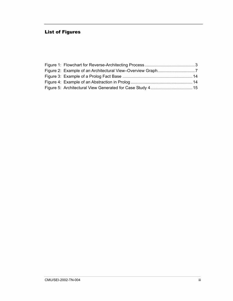
List of Figures
Figure 1: Flowchart for Reverse-Architecting Process...........................................3 Figure 2: Example of an Architectural View�Overview Graph................................7 Figure 3: Example of a Prolog Fact Base ............................................................14 Figure 4: Example of an Abstraction in Prolog .....................................................14 Figure 5: Architectural View Generated for Case Study 4....................................15
CMU/SEI-2002-TN-004 iii

iv CMU/SEI-2002-TN-004
Acknowledgments
The author would like to acknowledge the cooperation of Nokia in the generation of this report: in particular, Claudio Riva, Stefano Campadello, and Petri K. Laine, whose architecture reconstruction efforts form the basis for this experience report.
CMU/SEI-2002-TN-004 v

vi CMU/SEI-2002-TN-004
Executive Summary
This report outlines experiences from several architecture reconstruction efforts undertaken at Nokia. These efforts were performed on various systems including network management and mobile phone systems. The efforts involved the use of various tools and techniques, and in one of the efforts, the architecture reconstruction work was performed manually. This report describes these reconstruction efforts and outlines observations noted while performing them. It also identifies the overall lessons learned.
One of the main lessons learned was to obtain a high-level overview of the system before the reconstruction process begins, as this helps to identify the information that needs to be extracted and guides the generation of the architectural views. Reconstructing a system is easier if it uses good naming conventions and has been decomposed into a hierarchical directory structure.
It is important to have tools to support the reconstruction effort because they reduce the amount of time required, compared to a manual reconstruction effort. Tools cannot carry out an entire reconstruction automatically, and the tools used must be combined and integrated, since no one tool can support all of the tasks involved in reconstruction.
CMU/SEI-2002-TN-004 vii

viii CMU/SEI-2002-TN-004
Abstract
This experience report outlines details of past and current architecture reconstruction work on several systems at Nokia. The Dali architecture reconstruction workbench developed by the Software Engineering Institute supported some of these efforts. Other efforts involved various tools and techniques, and in one case, the architecture reconstruction was performed manually.
This report describes five such reconstruction efforts and outlines the observations noted and lessons learned while performing them. This report also offers some guidelines for those undertaking a reconstruction effort.
CMU/SEI-2002-TN-004 ix

x CMU/SEI-2002-TN-004
1 Introduction
Several architecture reconstruction projects have been undertaken at Nokia on systems in the network management and mobile phone domains. Nokia is the world leader in mobile communications. Worldwide, Nokia employs about 60,000 people and is separated into four main business groups:
1. Nokia Networks (NET) supplies mobile broadband, Internet Protocol (IP) network infrastructure, and related services. NET also develops mobile Internet applications and solutions for operators and Internet service providers.
2. Nokia Mobile Phones (NMP) is the world�s largest mobile phone manufacturer.
3. Nokia Research Center (NRC) drives Nokia�s technological competitiveness and renewal, through cooperation with Nokia�s other business groups, universities, research institutes, and other corporations.
4. Nokia Ventures Organization develops innovative ideas for the home, the environment, and the corporate world, expanding Nokia�s business scope.
Within the NRC, the Software Architecture group provides architecture-related services throughout Nokia. The case studies outlined in this report were performed mainly by personnel in the Software Architecture group working with project members from other parts of Nokia.
1.1 Reconstruction Efforts Performed Nokia personnel have performed several projects in architecture reconstruction on various systems within Nokia. The following architecture reconstruction case studies were examined as part of this report:
• NET on a system implemented in C
• NET on a system implemented in C++ and Java. (Only the part of the system implemented in Java was considered for architecture reconstruction.)
• two cases with NMP on a system implemented in C++
• NMP on a system implemented in C on which the Dali architecture reconstruction workbench1 was not used. The main concern here was that dynamic analysis was needed.
Java and all Java-based marks are trademarks of Sun Microsystems, Inc. in the U.S. and other
countries. 1 The Dali architecture reconstruction workbench was developed by the Software Engineering
Institute (SEI) [SEI 01].
CMU/SEI-2002-TN-004 1
• a manual architecture reconstruction effort on an embedded system within NET implemented in C++
The first three cases were performed with the support of Dali. The fourth case study was performed with the support of other technology, and in the last case, no reengineering tools were used to support the effort except generic UNIX utilities such as Emacs (a text editor) and Grep (a utility that searches files for particular string patterns).
The details of these case studies will be outlined in the following sections. Section 2 contains details of the first three case studies. These studies have been grouped because a similar approach was used in each, and the same technology (i.e., Dali) was used to support them. Section 3 contains details of the fourth case study, and Section 4 outlines details of the manual reconstruction effort. Each of these sections contains a list of observations highlighted during the reconstruction projects. Section 5 outlines an overall set of observations and lessons learned, which can guide other organizations that are thinking of undertaking similar architecture reconstruction work. Section 6 concludes this report by summarizing the main observations and lessons learned.
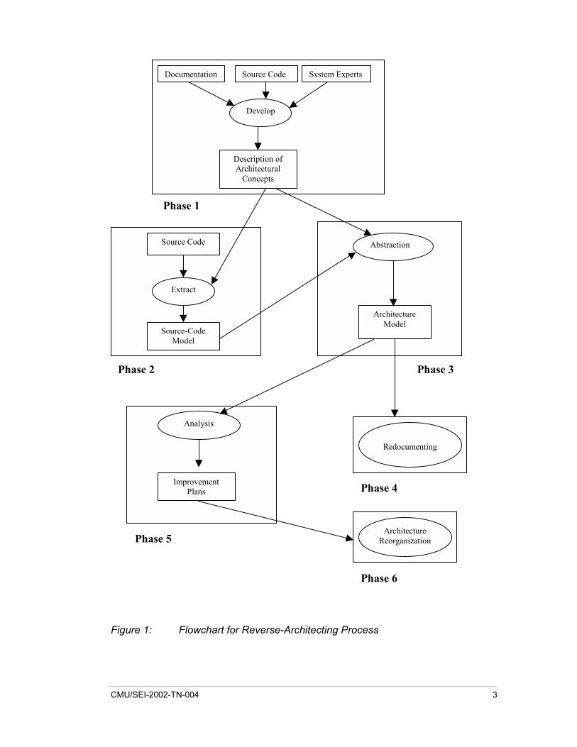
1.2 Architecture Reconstruction Process In each case where tools were used to support the architecture reconstruction, most of the process depicted in Figure 1 was followed. Not all of the phases in the process were performed in each of the projects, and in most cases there were different goals, objectives, and questions that the architecture reconstruction effort attempted to answer. In most cases, the work on the reconstruction project was complete once the architectural views of the system were documented, the questions were answered, and the objectives were achieved. In other cases, the goal of the architecture reconstruction work was to support decision making and not to improve or reorganize the structure of the system.
2 CMU/SEI-2002-TN-004
Documentation Source Code System Experts
Develop
Description of Architectural
Concepts
Source Code
Extract
Source-Code Model
Abstraction
Architecture Model
Redocumenting
Analysis
Improvement Plans
Architecture Reorganization
Phase 1
Phase 2 Phase 3
Phase 4
Phase 5
Phase 6
Figure 1: Flowchart for Reverse-Architecting Process
CMU/SEI-2002-TN-004 3
2 Case Studies 1, 2, and 3
Several reconstruction efforts have been supported by Dali [SEI 01]. Some of these efforts have already been completed, while others are ongoing.
The three architecture reconstruction efforts supported by Dali and covered in these case studies include
1. a network management system with NET implemented in C
2. a second network management system with NET implemented in C++ and Java. (Only the part of the system implemented in Java was considered for architecture reconstruction.)
3. a mobile phone system with NMP implemented in C++
2.1 C System An architecture reconstruction effort was started to fully understand a network system that Nokia acquired. The goal was to understand how to improve the system.
The project began with the use of a manual architecture reconstruction effort before tools were used. The system consisted of embedded distributed software on a VxWorks platform with several applications running on it. The main focus of the reconstruction effort involved understanding the communication mechanisms between various components, which were mainly based on sockets; however, it was also possible for components to communicate using remote procedure calls (RPCs).
The system also consisted of management software and hardware control software (device drivers). The main communication mechanisms used in this part of the software consisted mostly of sockets, pipes, signals, and queues.
The system was approximately 500 KLOC (thousand lines of code) of C plus a user interface (UI) subsystem for network management. This UI subsystem was not part of the reconstruction project.
Different views of the software existed from different sources. The main sources were customers, documentation, and makefiles. (The makefiles were not analyzed in this example.)
The documentation for the system, where available, was not well organized. Documents existed for different scenarios based upon several tasks that the system could undertake. Thus the documentation was feature oriented and omitted detailed information about the software
4 CMU/SEI-2002-TN-004
components and their interrelationships. System users needed to have detailed knowledge about the system before they could use the documentation.
2.1.1 Extraction of the Source-Code Model Initially SNiFF+ (a source-code analysis environment) was used to analyze the software and extract information [Wind River 02]. Several problems were encountered; for example, the tool could not handle the amount of code, and multiple instances of the same symbol in the SNiFF+ symbol table were not handled well. The main problem with using SNiFF+ was that external function call references were not highlighted as function calls. (This was a known problem in an earlier version of SNiFF+ that was used.) It was impossible to do useful analysis of the software using SNiFF+.
To extract information from the software so that it could be analyzed, several scripts were written using the Perl Web-programming language. The types of information extracted using Perl scripts included
• the directory structure of how the software is organized
• function calls
• information about the communication between the various components. This information included socket use, task queues, pipe use, and so forth, and was available through static analysis of the software.
The main software entities of most relevance to this study included functions (declared in .h files and defined in .c files), files, directories, and subsystems. (There was no direct mapping between subsystems and directories.)
Tasks are executed by function invocations within certain components. A function call to the task_spawn() function (passing the name of the task to be invoked) was used to initiate a task. Tasks can communicate using pipes, queues, and signals. A set of custom functions wrapped the lower-level pipes, queues, and signal calls.
Perl scripts were used to print out all function calls and architecturally significant function calls (socket write, task spawn, signal send, etc.) in Rigi Standard Format (RSF).2
During the project, there was a move away from using Perl scripts, and a decision was made to use Source-Navigator [Red Hat 01]. Using it overcame a problem with external function calls not being properly identified. Using pattern detection within Source-Navigator, it was possible to select particular functions and identify all the parameters in the function call. This was the same information that the Perl scripts extracted.
SNiFF+ is a trademark of Wind River Systems, Inc. 2 RSF is a tuple-based data format in the form of relationship entity_1 entity_2 [Müller 93]. Source-Navigator is a trademark of Red Hat, Inc.
CMU/SEI-2002-TN-004 5
Using Source-Navigator overcame some of the problems in using Perl scripts; however the following were still issues:
• Patterns may change between different releases of the same software; therefore, there is a potential for a large amount of work in the management of these patterns. No other tools were identified that could extract the required information without a similar detailed pattern definition (as was required in this work).
• Multiple symbols with the same name were not uniquely identifiable when extracted. A significant amount of work is required to uniquely identify these symbols that have the same name and to properly sort out all of the references to these symbols within the system code. Some work on overcoming this problem is being done by other research groups, such as Beszédes� work on the Columbus reverse-engineering tool [Beszédes 02].
2.1.2 Generation of the Architecture Model Once the information was extracted, it was loaded into Dali�s PostgreSQL database, and a set of about 20 queries was developed to generate various views of the architecture. Creating various component groupings and then building other layers of architectural abstraction on top of that allowed for the generation of various architectural views [Kazman 01]. In all, there were three levels of architectural views.
Overview graphs in Rigi were built using this information. An example of the types of graphs generated is shown in Figure 2. This shows a set of components�User Interface 1, User Interface 2, Servers, and Testing Support�and a set of relations between them. In this case, the relations between the nodes are an aggregate of the lower-level relations between the elements that make up these components.
6 CMU/SEI-2002-TN-004
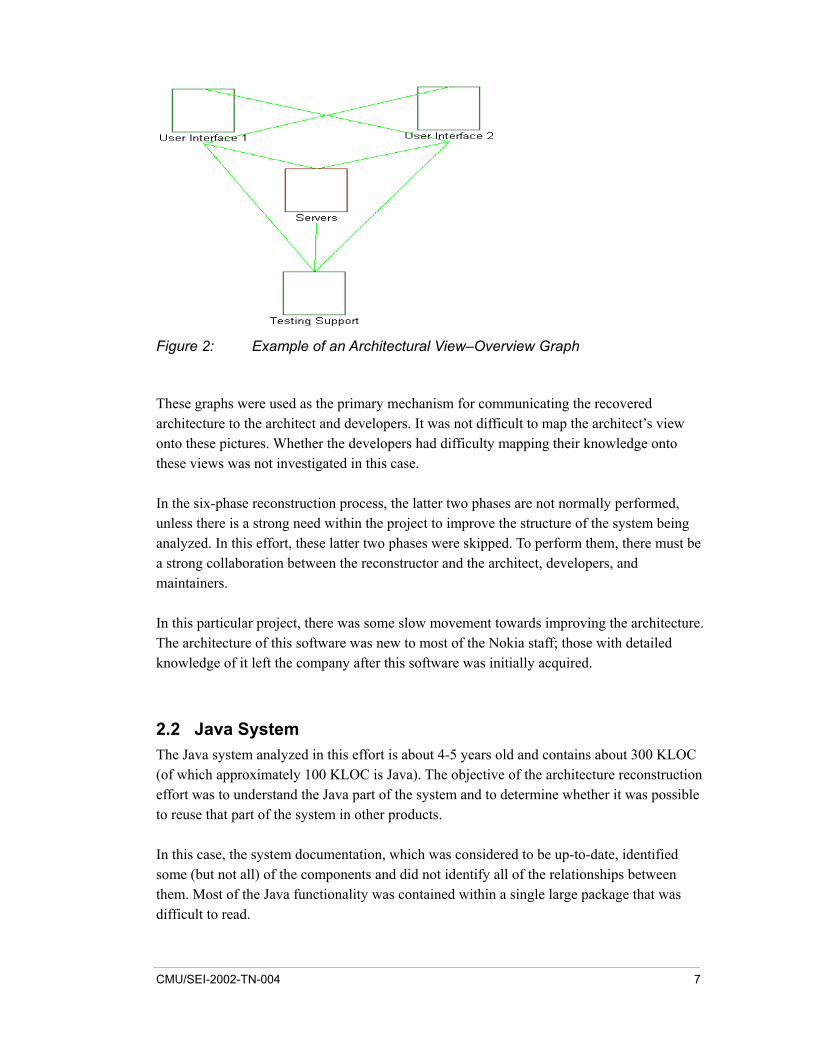
Figure 2: Example of an Architectural View�Overview Graph
These graphs were used as the primary mechanism for communicating the recovered architecture to the architect and developers. It was not difficult to map the architect�s view onto these pictures. Whether the developers had difficulty mapping their knowledge onto these views was not investigated in this case.
In the six-phase reconstruction process, the latter two phases are not normally performed, unless there is a strong need within the project to improve the structure of the system being analyzed. In this effort, these latter two phases were skipped. To perform them, there must be a strong collaboration between the reconstructor and the architect, developers, and maintainers.
In this particular project, there was some slow movement towards improving the architecture. The architecture of this software was new to most of the Nokia staff; those with detailed knowledge of it left the company after this software was initially acquired.
2.2 Java System The Java system analyzed in this effort is about 4-5 years old and contains about 300 KLOC (of which approximately 100 KLOC is Java). The objective of the architecture reconstruction effort was to understand the Java part of the system and to determine whether it was possible to reuse that part of the system in other products.
In this case, the system documentation, which was considered to be up-to-date, identified some (but not all) of the components and did not identify all of the relationships between them. Most of the Java functionality was contained within a single large package that was difficult to read.
CMU/SEI-2002-TN-004 7
Source-Navigator was used to extract the entities and relationships from the source code. Then this information was loaded into Dali, where components were identified and architectural views were generated. One of the problems using Source-Navigator was that many symbols were extracted (including types, constants, system functions, and variables), but could not be assigned actual types within Dali. However, this did not affect the ability to generate architectural views.
As this project progressed, it became apparent that some of the dependencies identified using the tools had not been identified in the documentation and that some of the dependencies contained in the documentation were incorrect. This was partly due to the implementation in which some connections between components and certain implementation decisions were not documented properly.
Using the directory structure of how the software was decomposed and the available documentation, components within the system were identified. The system was decomposed into a logical structure, thus making it easy to use queries to group elements into components and to produce abstractions of that information.
Several areas of the code were examined to determine if they could be reused. In particular, the interactions between classes were examined through the generation of class-interaction graphs. Cycles within these graphs mean that the classes are highly coupled and that there is the potential for classes within a cycle to have an effect on other classes. For example, an object from one class may change something in the environment that will, in turn, change the behavior of objects from another class. This makes reusing the classes difficult.
Another area that was examined in this study was the structure of the exceptions, which affects performance. From the views generated, it was clear that some exceptions were being inherited from more than one class and that most classes had exceptions. All of these factors may adversely affect the decision to reuse the component.
2.3 C++ System This system is a mobile device prototype of approximately one MLOC (million lines of code) implemented in C++. It is integrated with the Symbian operating system for mobile devices, which has libraries that can be used for building applications. There were two main objectives for this study:
1. Examine the integration of the operating system with Nokia�s application and identify specifically how messages were exchanged between the applications and Symbian.
2. Analyze a particular component (developed by Nokia) and determine if it could be extracted and then reused in other products.
8 CMU/SEI-2002-TN-004
2.3.1 Examining the Integration To begin the analysis, high-level message sequence charts were generated with the developers� help so that the reconstructor could obtain a high-level understanding of the system. The overall structure of the basic Symbian engine consists of clients and an internal server. The clients connect to the server with a static connect by statically calling a server function. The server has several classes, representing the messages that can be passed between the clients and server.
The method applied to extract source information involved
• extracting object-oriented (OO) entities and references among them
• using Grep for detecting code patterns (for example, identifying calls to particular functions)
• performing direct analysis of source files using regular expressions
The output of the extraction was a file in RSF, which contained the set of entities and relationships. This file was loaded into Dali, where abstractions were created using several aggregation and grouping techniques.
The types of aggregations and groupings employed included
• aggregating methods and attributes within classes
• aggregating classes and files within directories
• grouping directories to form components
From these aggregations and groupings, it was possible to generate several architectural views of the system. From these views, it was possible to identify the connections between the operating system components and the applications running on top of the operating system.
Work is ongoing with the developers to reconstruct the architecture with a view to improving it.
2.3.2 Analyzing the User Interface (UI) Component The second effort involved analyzing a particular component developed by Nokia. The goal of the reconstruction work was to examine this component to determine if it could be extracted and reused in other products.
The same process for extracting information that was outlined earlier was followed in this case. It is important to note that even though this project focused on a particular part of the system, all of the system code had to be analyzed so that all dependencies were highlighted.
CMU/SEI-2002-TN-004 9
As the information was being extracted from the source code, a problem was identified: when analyzing large systems, more than one symbol (such as a variable or function) may have the same name. These name clashes must be identified and sorted out (i.e., symbols must be given unique names); otherwise, the views generated may include misleading connections between components. It may be impossible to identify the function or class that one of these symbols references without compiling/linking the source code. The linker in the compilation process sorts out any name clashes.
By preprocessing and linking, most of the problems with duplicate names are eliminated because the symbol names must be unique. However nonunique names still occur in most of the information that is extracted statically from source code.
In this effort, the report facility from Rigi was used to generate information, which was then copied into the report. This effort identified many dependencies between the component and the rest of the system. This work is ongoing and has continued into 2002, as a much larger task is being planned. This larger task involves extracting the architecture of the entire system to identify what is already there and to determine whether it would be possible to generalize and reuse other parts of the system.
The architects found that the architectural views generated by the tools had sufficient information to answer their questions and presented the information clearly.
2.4 Observations for Case Studies 1, 2, and 3 The following observations were noted while undertaking these reconstruction efforts:
• Obtain a high-level (logical) view of the architecture before starting the extraction. This enables you to get an understanding of what to look for when extracting information from the system and undertaking the reconstruction. Otherwise, you may not extract the right information from the software and may spend time trying to build abstractions of less useful information.
• If possible, write patterns for extracting information from the source code that are easily applicable in other situations. This can save time during other reconstruction efforts.
• Dynamic analysis and views of the system are important for certain types of systems, such as those with late binding and those that may be configured dynamically. Understanding how a particular feature is implemented in the system may require dynamic analysis. Dynamic views of the system such as the sequence of the calls (the order in which the calls are executed) would be useful because they can show which parts of a system are involved in the implementation of a particular feature.
• There should be someone working full-time on the architecture reconstruction project. Architecture reconstruction involves an extensive, detailed analysis of a system and requires a significant effort.
10 CMU/SEI-2002-TN-004
• Have a list of architecturally relevant information to look for in the code. Is there a list of code constructs/patterns to look for? Once a pattern is selected, highlight the code, or instances in the code, where this pattern occurs.
• Sometimes information within data structures in the code (such as a struct in C) may be architecturally relevant. For example, a data structure may list a set of functions that can potentially be called at runtime. If a function pointer that points to this data structure is used, identifying the structure�s function names can provide useful information to the reconstruction effort. It is necessary to parse this information and possibly load it into the database so that it is available for later analysis.
• To gain people�s confidence in architecture reconstruction methods and tools, it may help to undertake a pilot project to show the benefits of using them.
• Architecture reconstruction tools could also be used when a system is being developed to check the conformance of the software architecture to some reference architecture.
• Architecture reconstruction tools should not be complicated to use. The time spent learning how to use a particular tool could consume a large portion of the effort required to do the architecture reconstruction work itself.
• The ability to have better integration/connection across tools would be very useful for navigating the information generated from the reconstruction effort. For example, when a graphical view is generated, it should be possible to click on a node or connection to go directly to the source code to identify what that connection means.
CMU/SEI-2002-TN-004 11
3 Case Study 4 - Dynamic Analysis
The fourth reconstruction effort was on a software product family.3 The software system consisted of about 1.5 MLOC written in C and was more object based than object oriented. In the product family, there are about 10 products per year (this number is increasing), and there are variances across these products in terms of the device category, telecommunications protocol, UI, operating system services, and customer/country customization.
Products are organized in families to achieve reusability, thus driving the need to have a robust architecture that is shared by all family members. Organizing products as families also generates dependencies across platforms and products. The development process for these products is geographically distributed and concurrent. Reducing dependencies and reusing components across several products should reduce costs. Maintaining the vast portfolio of products is a huge challenge.
The goal of this case study was to develop techniques and tools to understand how the features within each product relate to the set of components and to identify the components� dependencies. The components that implement a feature are potentially the same ones that can be shared across products. The architecture reconstruction techniques and tools were applied on various example products. If the applications were successful, these techniques and tools would be incorporated into the development team�s work so that the developers could examine the dependencies when adding new features or modifying code. An early report on this work appears in the Proceedings of the Seventh Working Conference on Reverse Engineering [Riva 00]. A further report on this work will appear in the Proceedings of the Sixth European Conference on Software Maintenance and Reengineering.4 This work started before Nokia acquired Dali.
Using architecture reconstruction/reverse-engineering approaches, the following levels of abstraction were identified:
• code
• design
• architecture 3 A software product family in the Nokia context is the same thing as a software product line in SEI
terminology: a set of software-intensive systems sharing a common, managed set of features that satisfy the specific needs of a particular market segment or mission and that are developed from a common set of core assets in a prescribed way [Clements 01].
4 Riva, C. & Rodriguez, V. J. �Combining Static and Dynamic Views for Architecture Reconstruction.� Proceedings of the Sixth European Conference on Software Maintenance and Reengineering (CSMR 2002). Los Alamitos, CA: IEEE Computer Society Press, to be published.
12 CMU/SEI-2002-TN-004
• feature (This is not a direct mapping between features and components in the architecture.)
• requirements
The approach was to identify these static views of the architecture and to use dynamic analysis to slice through them to identify the components that are involved in the implementation of a particular feature. In generating these views, a class-inheritance diagram was generated and found to be very flat, indicating that there were just a few generic classes from which most specialized classes were inherited. The following problems were identified in trying to reconstruct the architecture:
• The source files were generated by a computer-aided software engineering (CASE) tool, thus making it difficult to parse the code.
• Existing source-code analyzers were not sufficient to achieve the goal of the project.
• Poor naming conventions were used.
• Because the implementation language was nonstandard, it was difficult to get tools to analyze it.
3.1 Generation of the Architecture Model In this case, a high-level overview of the system was obtained. This overview guided the extraction of information from the source so that useful architectural views of the system could be built. The relevant architecture components consisted of servers, clients, applications, and delegate applications with message passing between these various components along a software bus. The code entities that were extracted included directories, files, and applications; the relationships that were extracted included send_message, subscribe_event, and calls.
From the static analysis, it was possible to identify the server to which messages were sent. There was a SEND function whose first parameter was the name of the server to which the message was routed. Knowing this made the work much easier and eliminated the need for a more detailed analysis (including dynamic analysis) to identify the destination of messages. Several architectural views consisting of the applications (directories) and servers were generated from the information.
One of the difficulties in this project was the lack of support for automating the architecture reconstruction process. This project was undertaken before Nokia acquired Dali. (Using Dali has overcome some of these difficulties for other Nokia projects.)
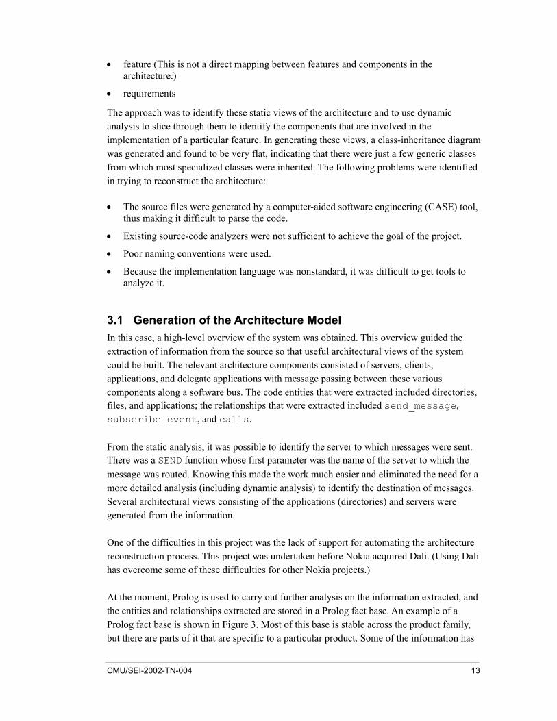
At the moment, Prolog is used to carry out further analysis on the information extracted, and the entities and relationships extracted are stored in a Prolog fact base. An example of a Prolog fact base is shown in Figure 3. Most of this base is stable across the product family, but there are parts of it that are specific to a particular product. Some of the information has
CMU/SEI-2002-TN-004 13
to be entered into the Prolog system manually by the architect, who, as a result, must become familiar with Prolog and the developed system to do further abstraction.
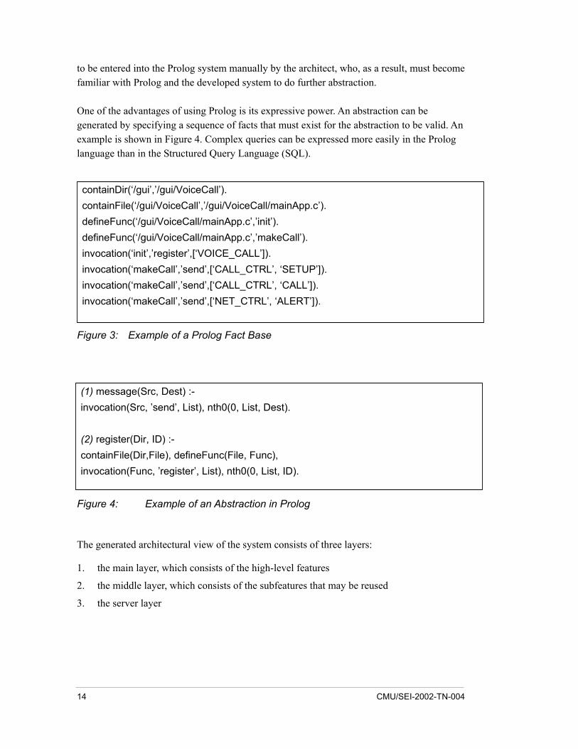
One of the advantages of using Prolog is its expressive power. An abstraction can be generated by specifying a sequence of facts that must exist for the abstraction to be valid. An example is shown in Figure 4. Complex queries can be expressed more easily in the Prolog language than in the Structured Query Language (SQL).
containDir(�/gui�,�/gui/VoiceCall�).containFile(�/gui/VoiceCall�,�/gui/VoiceCall/mainApp.c�).defineFunc(�/gui/VoiceCall/mainApp.c�,�init�).defineFunc(�/gui/VoiceCall/mainApp.c�,�makeCall�).invocation(�init�,�register�,[�VOICE_CALL�]).invocation(�makeCall�,�send�,[�CALL_CTRL�, �SETUP�]).invocation(�makeCall�,�send�,[�CALL_CTRL�, �CALL�]).invocation(�makeCall�,�send�,[�NET_CTRL�, �ALERT�]).
Figure 3: Example of a Prolog Fact Base
(1) message(Src, Dest) :-invocation(Src, �send�, List), nth0(0, List, Dest).
(2) register(Dir, ID) :-containFile(Dir,File), defineFunc(File, Func),invocation(Func, �register�, List), nth0(0, List, ID).
Figure 4: Example of an Abstraction in Prolog
The generated architectural view of the system consists of three layers:
1. the main layer, which consists of the high-level features
2. the middle layer, which consists of the subfeatures that may be reused
3. the server layer
14 CMU/SEI-2002-TN-004
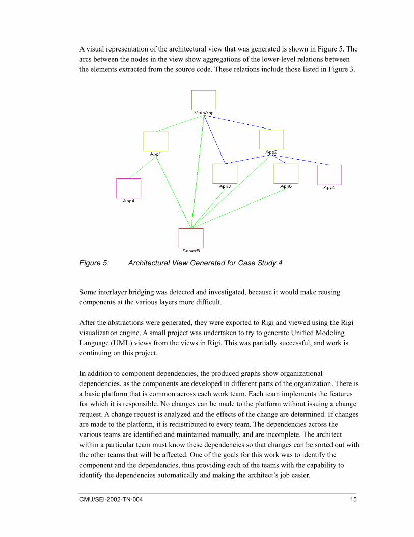
A visual representation of the architectural view that was generated is shown in Figure 5. The arcs between the nodes in the view show aggregations of the lower-level relations between the elements extracted from the source code. These relations include those listed in Figure 3.
Figure 5: Architectural View Generated for Case Study 4
Some interlayer bridging was detected and investigated, because it would make reusing components at the various layers more difficult.
After the abstractions were generated, they were exported to Rigi and viewed using the Rigi visualization engine. A small project was undertaken to try to generate Unified Modeling Language (UML) views from the views in Rigi. This was partially successful, and work is continuing on this project.
In addition to component dependencies, the produced graphs show organizational dependencies, as the components are developed in different parts of the organization. There is a basic platform that is common across each work team. Each team implements the features for which it is responsible. No changes can be made to the platform without issuing a change request. A change request is analyzed and the effects of the change are determined. If changes are made to the platform, it is redistributed to every team. The dependencies across the various teams are identified and maintained manually, and are incomplete. The architect within a particular team must know these dependencies so that changes can be sorted out with the other teams that will be affected. One of the goals for this work was to identify the component and the dependencies, thus providing each of the teams with the capability to identify the dependencies automatically and making the architect�s job easier.
CMU/SEI-2002-TN-004 15
As a result of this work, the architects have the first model that reflects the current architecture of their system. This model is navigable using Rigi, which the architects found to be very useful. One of the tasks that is currently being performed is the analysis of the INCLUDE file dependencies. This is a difficult task because of the different means of including files, multiple files with the same names, and the sequence of how the files are included.
Additional dynamic analysis of the system is being undertaken. Also, the sequence charts are being analyzed with static analysis to identify groupings in them in terms of the packages and components that constitute the system. This analysis would give views of the interactions between the high-level entities in the system.
3.2 Observations for Case Study 4 The following observations were noted while undertaking this reconstruction effort. Some of them can also be viewed as recommendations for developers and reconstructors.
• When developing a system, use design conventions that make it easier to recover the software architecture. For example, putting the name of the server in a function call that sends a message to the server is better than using some variable name as the server name and not being able to determine the value in the variable statically. If a variable name were used, dynamic analysis would be required to uncover the server name, thus making the reconstruction effort more difficult.
• Having unique names in a system helps in recovering the code�s architecture. Nonunique names must be reconciled before generating architectural views; otherwise nonexistent relationships between entities may be identified. Therefore, make sure that the information being used to build the high-level abstraction and architectural view is correct.
• Lightweight parsing of the code fully satisfied the needs on this project. Therefore, it is useful to determine what type of information you want to get from the system and whether lightweight parsing (using Perl and lexical analysis) or more heavyweight (full-blown) parsing is required.
• Mapping back from the architectural views that were generated to UML-type views would help the architecture reconstruction work. The UML seems to be the standard for architecture documentation, and other types of graphical views that are generated by tools add to the cognitive load of those trying to understand the system�s architecture.
• Talk with the architects in the language and graphical representations with which they are familiar. There is a need to generate not just box-and-arrow diagrams, but other semantic information as well. Interactive visualizations help to fill this need, as they provide not only the graphs, but also the ability to navigate through the information easily.
16 CMU/SEI-2002-TN-004
4 Case Study 5 - Manual Reconstruction Effort
This case study was on a mobile device system of about one MLOC of C++ code. The goal of this project was to determine what is required to understand the architecture of an OO system and to develop ideas that can be applied in its development. The specific objective of this work was to explore the role of software architecture in building OO systems. Laine discusses the findings of this study [Laine 01]. The outline given here looks at this work from the viewpoint of the architecture reconstruction effort undertaken in this work and highlights some of the issues involved in manual architecture reconstruction efforts.
4.1 Outline of the Manual Reconstruction A high-level overview of the system was generated. Then, starting at the code level, the reconstructor mapped back to the high-level overview to reason about the system, to determine how mapping is done, and to investigate the role that architecture plays.
The approach to the manual reconstruction effort was to generate a high-level view of the system and to assign code to various parts of that view. Certain components were identified directly by examining the code. Clustering and abstraction were used to build component views. No tools, such as Rational Rose, were used in generating the high-level views; rather just pen and paper were used to draw high-level diagrams. Doing so allowed for the free-form expression of ideas and links to code and other documentation.
This manual effort took three to four months of intensive study of the code. The reconstructor knew the architecture of the system quite well before starting this project. The only utilities that were used to support the manual effort were Emacs and Grep. The system was already decomposed into a directory structure, so it was relatively easy to know where to look for certain components. However, some inconsistencies in the placement of code within the directory structure were identified and highlighted. Also identified were some indirect and complex dependencies that were previously unknown and undocumented.
Information that was generated manually included call dependencies, class and package dependencies, and inheritance trees. Although no tools were used, much of this type of information can be generated more easily using tools. Since the information generated was captured mostly in free-hand drawings, it was not presented easily to others. Mapping the generated views to a tool such as the UML was not a straightforward task, so it was not done.
The task was to develop conclusions about the role of software architecture and to generate sufficient knowledge to back up those conclusions. For example, one question that was asked
CMU/SEI-2002-TN-004 17
about the system was, �Why does the system have particular properties?� To answer this question, the architecture of the entire system was reconstructed. As the project progressed, it was obvious that the existing documentation did not accurately reflect the existing system. Through the reconstruction and generation of the various views, the reconstructor was able to answer this and other questions.
One of the objectives of this work was to determine what is involved in ensuring that the architecture of the implemented system conforms to the architecture as it was envisioned and that nothing has been added to the system that is not in the architecture description. Having this type of conformance checking (i.e., �round-trip engineering�) could be part of the development process, as it provides a regular reality check. However, there are probably few development projects in which this is done.
Overall, tools could have supported this work by automating the extraction and abstraction of the information from the code to generate architectural views as shown in the earlier projects, but, as mentioned before, none were used. As the information being generated became more concrete, the use of free-form diagrams changed. In the early stages of the effort, the high-level information was captured in free-hand, box-and-arrow diagrams; but as the system became more familiar, the diagrams changed to be similar to those produced in the UML. Free-form diagrams were used because it is not easy to capture high-level views in a rigorous tool or methodology.
Although dynamic analysis was not performed in this reconstruction, it may have been useful.
4.2 Observations for Case Study 5 The following observations were noted while undertaking this reconstruction effort:
• It may be impossible to formalize all of the dependencies that exist in the software (e.g., if there are dependencies that occur at runtime and it is impossible to run the system to get the dynamic information). Therefore it is necessary to identify those dependencies that are important to the reconstruction effort, to make sure that they can be formalized, and to work around those that cannot.
• To undertake a manual reconstruction effort, you should know a great deal about the software; otherwise, it would very difficult to carry out the reconstruction work. In a large system, there can be a large amount of information, and it is necessary to determine which information is relevant and which is irrelevant to the task at hand.
• Recognizing the importance of certain concepts within the software is a manual effort. However, extracting these concepts from the software can be supported using tools.
• In many cases, the existing documentation for a system may not accurately reflect the system as it is implemented. Therefore it may be necessary to disregard the existing documentation and use it only to generate the high-level views of the system, since it should give an indication of the high-level concepts.
18 CMU/SEI-2002-TN-004
• Using tools to automatically perform many of the tasks that were performed manually could have significantly reduced the amount of time required to carry out the reconstruction project. Using utilities such as Emacs and Grep, it is possible to generate the call graph of a system, but it may take several hours or days to do so. Tools can build a system�s call graph in a matter of minutes, reducing the risk of human errors being introduced into the process. The ability to combine various tools is also important. (For example, linking source-code browsers to graphical tools makes navigation through the system much easier than having to switch between various tools.)
• Using the manual approach, the person undertaking the reconstruction got to know the system very well.
• When reconstructing the architecture of a system, a specific goal and set of objectives must exist to focus the effort.
CMU/SEI-2002-TN-004 19
5 Overall Observations and Lessons Learned
The following observations and lessons learned were gleaned from the projects and can be used as a set of guidelines for anyone undertaking or considering an architecture reconstruction effort:
• It is important to have a goal and set of objectives/questions in mind before undertaking the architecture reconstruction effort. Because a large amount of information can be extracted from the system�s source code, it is important to make sure that the extracted information and the analysis that is applied to it help satisfy the goal of the reconstruction effort. Without specific goals, your analysis may be useful, but may not satisfy the original goal or answer the questions you have about the system.
• Obtaining a high-level view of the system before beginning the detailed analysis is important because you need to know what to look for and what information to extract.
• Decomposing the system code into a hierarchical directory structure would aid the reconstruction effort, as this hierarchy should reflect the architecture of the software. Having only a few directories where code is lumped together adds to the confusion about the system�s structure and makes the reconstruction effort difficult. Good configuration-management tools can provide this information.
• Good naming conventions would assist in the reconstruction process. Therefore using them should be part of the software development standards. Reconstructing a system that has a good architecture and that has been worked on by disciplined programmers is easier than reconstructing a system that has a bad architecture and that has been worked on by ill-disciplined programmers.
• It is important to involve the maintainers or developers at an early stage of the reconstruction effort, as this helps you to understand the system being analyzed and to identify what to look for in the system to satisfy the effort�s goals and objectives and to answer your questions.
• Tools can support the reconstruction effort and shorten the reconstruction process, but they cannot do an entire reconstruction effort automatically. The work requires the involvement of people who are familiar with the system. (This point was key in the decision to develop Dali to be open and interactive.)
• The ability to combine various tools to support the reconstruction effort is very important. No single tool can provide the necessary functionality, so the ability to integrate tools easily is required. (This point was also key in the decision to develop Dali to be open and interactive.)
20 CMU/SEI-2002-TN-004
6 Conclusions
Nokia used Dali to great effect within its own organization. Overall, its architecture reconstruction efforts have been very successful in providing information that enables the system architects and developers to better understand their systems and to make strategic decisions about them. Some improvements have been made in documenting systems, specifically using tools to support the documentation and the processes used to understand the software.
Architecture reconstruction was very useful in a variety of contexts and with differing goals and objectives. As outlined in this report, reconstruction was performed on software for mobile devices and network management systems, with objectives ranging from gaining an understanding of various systems to determining if system parts can be generalized and reused in other products. Reconstruction was used on product families as well as individual systems and on a variety of different implementation languages.
Tool support is required for architecture reconstruction, and there are tools that can support the process. However, research and development on improving the reconstruction process and on tools that can better support the process needs to continue.
CMU/SEI-2002-TN-004 21

22 CMU/SEI-2002-TN-004
References
[Beszédes 02] Beszédes, Á. �List of Publications of Árpád Beszédes� [online]. <http://www.inf.u-szeged.hu/~beszedes/research/eng/> (2002).
[Clements 01] Clements, P. & Northrop, L. Software Product Lines: Practices and Patterns. Boston, MA: Addison-Wesley, 2001.
[Kazman 01] Kazman, R.; O�Brien, L.; & Verhoef, C. Architecture Reconstruction Guidelines (CMU/SEI-2001-TR-026, ADA395198). Pittsburgh, PA: Software Engineering Institute, Carnegie Mellon University, 2001. <http://www.sei.cmu.edu/publications/documents/01.reports/ 01tr026.html>.
[Laine 01] Laine, P. K. �The Role of Software Architecture in Solving Fundamental Problems in Object-Oriented Development of Large Embedded Systems,� 14-23. Proceedings of the Working IEEE/IFIP Conference on Software Architecture. Amsterdam, The Netherlands, August 28-31, 2001. Los Alamitos, CA: IEEE Computer Society, 2002.
[Müller 93] Müller, H. A.; Mehmet, O. A.; Tilley, S. R.; & Uhl, J. S. �A Reverse Engineering Approach to System Identification.� Journal of Software Maintenance: Research and Practice 5, 4 (December 1993): 181-204.
[Red Hat 01] Red Hat, Inc. �The Source-Navigator IDE� [online]. <http://sources.redhat.com/sourcenav/> (2001).
[Riva 00] Riva, C. �Reverse Architecting: An Industrial Experience Report,� 42-50. Proceedings of the Seventh Working Conference on Reverse Engineering. Brisbane, Australia, November 23-25, 2000. Los Alamitos, CA: IEEE Computer Society, 2000.
[SEI 01] Software Engineering Institute. �Architecture Reconstruction� [online]. <http://www.sei.cmu.edu/ata/ata_extraction.html> (2001).
[Wind River 02] Wind River Systems, Inc. �SNiFF+� [online]. <http://www.windriver.com/products/html/sniff.html> (2002).
CMU/SEI-2002-TN-004 23

24 CMU/SEI-2002-TN-004
REPORT DOCUMENTATION PAGE Form Approved OMB No. 0704-0188
Public reporting burden for this collection of information is estimated to average 1 hour per response, including the time for reviewing instructions, searching existing data sources, gathering and maintaining the data needed, and completing and reviewing the collection of information. Send comments regarding this burden estimate or any other aspect of this collection of information, including suggestions for reducing this burden, to Washington Headquarters Services, Directorate for information Operations and Reports, 1215 Jefferson Davis Highway, Suite 1204, Arlington, VA 22202-4302, and to the Office of Management and Budget, Paperwork Reduction Project (0704-0188), Washington, DC 20503. 1. AGENCY USE ONLY
(Leave Blank) 2. REPORT DATE
March 2002 3. REPORT TYPE AND DATES COVERED
Final 4. TITLE AND SUBTITLE
Experiences in Architecture Reconstruction at Nokia 5. FUNDING NUMBERS
F19628-00-C-0003 6. AUTHOR(S)
Liam O�Brien 7. PERFORMING ORGANIZATION NAME(S) AND ADDRESS(ES)
Software Engineering Institute Carnegie Mellon University Pittsburgh, PA 15213
8. PERFORMING ORGANIZATION REPORT NUMBER
CMU/SEI-2002-TN-004
9. SPONSORING/MONITORING AGENCY NAME(S) AND ADDRESS(ES) HQ ESC/XPK 5 Eglin Street Hanscom AFB, MA 01731-2116
10. SPONSORING/MONITORING AGENCY REPORT NUMBER
11. SUPPLEMENTARY NOTES
12A DISTRIBUTION/AVAILABILITY STATEMENT
Unclassified/Unlimited, DTIC, NTIS 12B DISTRIBUTION CODE
13. ABSTRACT (MAXIMUM 200 WORDS)
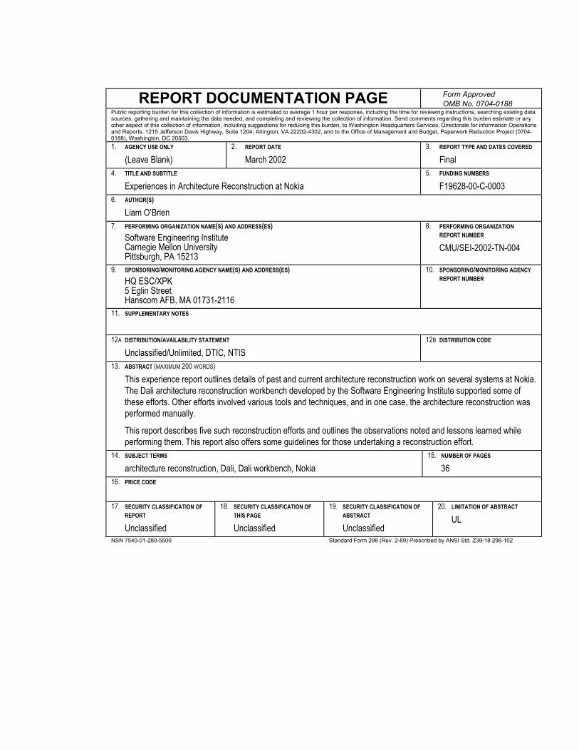
This experience report outlines details of past and current architecture reconstruction work on several systems at Nokia. The Dali architecture reconstruction workbench developed by the Software Engineering Institute supported some of these efforts. Other efforts involved various tools and techniques, and in one case, the architecture reconstruction was performed manually.
This report describes five such reconstruction efforts and outlines the observations noted and lessons learned while performing them. This report also offers some guidelines for those undertaking a reconstruction effort.
14. SUBJECT TERMS
architecture reconstruction, Dali, Dali workbench, Nokia 15. NUMBER OF PAGES
36 16. PRICE CODE
17. SECURITY CLASSIFICATION OF
REPORT
Unclassified
18. SECURITY CLASSIFICATION OF THIS PAGE
Unclassified
19. SECURITY CLASSIFICATION OF ABSTRACT
Unclassified
20. LIMITATION OF ABSTRACT
UL
NSN 7540-01-280-5500 Standard Form 298 (Rev. 2-89) Prescribed by ANSI Std. Z39-18 298-102