Embed Size (px)
Citation preview
Exergy Int. J. 1(1) (2001) 31–40www.exergyonline.com
Exergoeconomic analysis of gas turbine cogenerationsystems
Yong-Ho Kwon a, Ho-Young Kwak a∗, Si-Doek Ohb
a Mechanical Engineering Department, Chung-Ang University, Seoul 156-756, South Koreab Energy Team, Research & Development Institute, Hyosung Industries Co. Ltd., Seoul 121-020, South Korea
(Received 8 December 1999, accepted 3 January 2000)
Abstract—A thermodynamic for the effect of the annualized cost of a component on the production cost in 1000 kW gas-turbinecogeneration system was studied by utilizing the generalized exergy balance and cost-balance equations developed previously.Comparison between typical exergy-costing methodologies were also made by solving a predefined cogeneration system, CGAMproblem. It was successful to identity the component which affects the unit cost of system’s products decisively. It has been foundthat the cost of products are crucially dependent on the change in the annualized cost of the component whose primary product isthe same as the system’s product. On the other hand, the change in the weighted average cost of the product is proportional to thechange in the annualized cost of the total system. 2001 Éditions scientifiques et médicales Elsevier SAS
Nomenclature
C unit cost of production . . . . . . . . $·kJ−1
C0 unit cost of exergy of fuel . . . . . . $·kJ−1
Ci initial investment cost . . . . . . . . . $CRF(i, n) capital recovery factorC monetary flow rate . . . . . . . . . . $·year
CP specific heat . . . . . . . . . . . . . . kJ·kg·K−1
d cost per unit mass . . . . . . . . . . . $·kg−1
e specific exergy . . . . . . . . . . . . . MJ·kg−1
Ex rate of exergy flow . . . . . . . . . . kW
h enthalpy per unit mass . . . . . . . . kJ·kg−1
i interest ratem mass flow rate . . . . . . . . . . . . . kg·s−1
P pressurePW present worthPWF(i, n) present worth factor
Si entropy flow rate . . . . . . . . . . . kJ·K−1
Sn salvage value . . . . . . . . . . . . . $T temperature . . . . . . . . . . . . . . KT0 ambient temperature
Zk capital cost rate of unit k . . . . . . . $·s−1
∗ Correspondence and reprints.E-mail address: [email protected] (H.-Y. Kwak).
Greek symbols
φk maintenance factorηe exergy efficiency
Subscripts
a airBQ steamf fuelk kth component0 standard stateP mechanical exergyS negentropyT thermal exergyW work or electricity
Superscripts
BQ steamCHE chemicalm materialP mechanicalT thermalW work or electricity
2001 Éditions scientifiques et médicales Elsevier SAS. All rights reserved 31S1164-0235(01)00007-3/FLA
Y.-H. Kwon et al. / Exergy Int. J. 1(1) (2001) 31–40
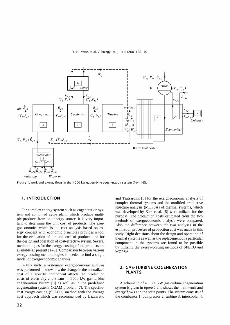
Figure 1. Work and exergy flows in the 1000 kW gas-turbine cogeneration system (from [6]).
1. INTRODUCTION
For complex energy system such as cogeneration sys-tem and combined cycle plant, which produce multi-ple products from one energy source, it is very impor-tant to determine the unit cost of products. The exer-goeconomics which is the cost analysis based on ex-ergy concept with economic principles provides a toolfor the evaluation of the unit cost of products and forthe design and operation of cost-effective system. Severalmethodologies for the exergy-costing of the products areavailable at present [1–5]. Comparison between variousexergy-costing methodologies is needed to find a singlemodel of exergoeconomic analysis.
In this study, a systematic exergoeconomic analysiswas performed to know how the change in the annualizedcost of a specific component affects the productioncosts of electricity and steam in 1 000 kW gas-turbinecogeneration system [6] as well as in the predefinedcogeneration system, CGAM problem [7]. The specific-cost exergy costing (SPECO) method with the averagecost approach which was recommended by Lazzaretto
and Tsatsaronis [8] for the exergoeconomic analysis ofcomplex thermal systems and the modified productivestructure analysis (MOPSA) of thermal systems, whichwas developed by Kim et al. [5] were utilized for thepurpose. The production costs estimated from the twomethods of exergoeconomic analysis were compared.Also the difference between the two analyses in theestimation processes of production cost was made in thisstudy. Right decisions about the design and operation ofthermal systems as well as the replacement of a particularcomponent in the systems are found to be possibleby utilizing the exergy-costing methods of SPECO andMOPSA.
2. GAS-TURBINE COGENERATIONPLANTS
A schematic of a 1 000 kW gas-turbine cogenerationsystem is given in figure 1 and shows the main work andexergy flows and the state points. The system consists ofthe combustor 1, compressor 2, turbine 3, intercooler 4,
32
Y.-H. Kwon et al. / Exergy Int. J. 1(1) (2001) 31–40
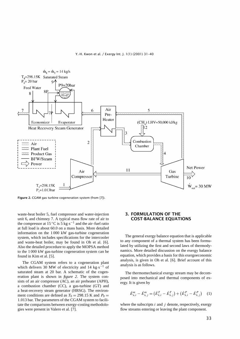
Figure 2. CGAM gas turbine cogeneration system (from [7]).
waste-heat boiler 5, fuel compressor and water-injectionunit 6, and chimney 7. A typical mass flow rate of air tothe compressor at 15 ◦C is 5 kg·s−1 and the air–fuel ratioat full load is about 60.0 on a mass basis. More detailedinformation on the 1 000 kW gas-turbine cogenerationsystem, which includes specifications for the intercoolerand waste-heat boiler, may be found in Oh et al. [6].Also the detailed procedure to apply the MOPSA methodto the 1 000 kW gas-turbine cogeneration system can befound in Kim et al. [5].
The CGAM system refers to a cogeneration plantwhich delivers 30 MW of electricity and 14 kg·s−1 ofsaturated steam at 20 bar. A schematic of the cogen-eration plant is shown in figure 2. The system con-sists of an air compressor (AC), an air preheater (APH),a combustion chamber (CC), a gas-turbine (GT) anda heat-recovery steam generator (HRSG). The environ-ment conditions are defined as T0 = 298.15 K and P0 =1.013 bar. The parameters of the CGAM system to facili-tate the comparisons between exergy-costing methodolo-gies were present in Valero et al. [7].
3. FORMULATION OF THECOST-BALANCE EQUATIONS
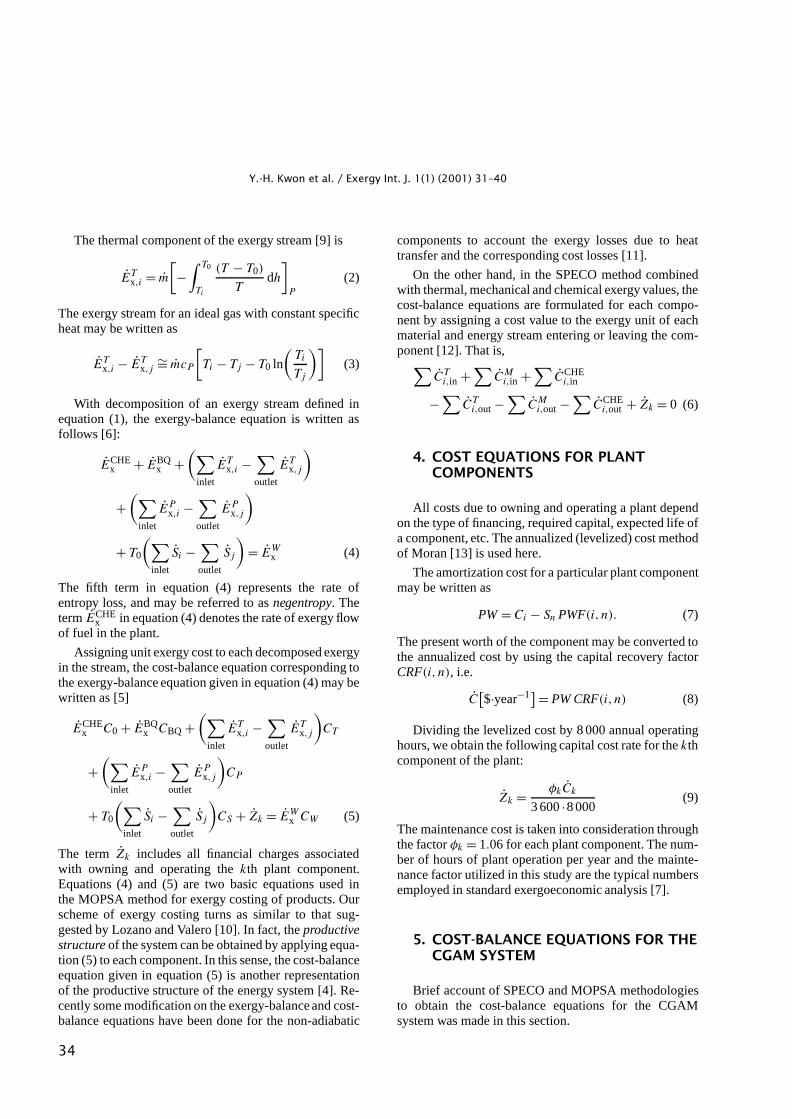
The general exergy balance equation that is applicableto any component of a thermal system has been formu-lated by utilizing the first and second laws of thermody-namics. More detailed discussion on the exergy balanceequation, which provides a basis for this exergoeconomicanalysis, is given in Oh et al. [6]. Brief account of thisanalysis is as follows.
The thermomechanical exergy stream may be decom-posed into mechanical and thermal components of ex-ergy. It is given by
Emx,i − Em
x,j = (ET
x,i − ETx,j
) + (EP
x,i − EPx,j
)(1)
where the subscripts i and j denote, respectively, exergyflow streams entering or leaving the plant component.
33
Y.-H. Kwon et al. / Exergy Int. J. 1(1) (2001) 31–40
The thermal component of the exergy stream [9] is
ETx,i = m
[−
∫ T0
Ti
(T − T0)
Tdh
]P
(2)
The exergy stream for an ideal gas with constant specificheat may be written as
ETx,i − ET
x,j∼= mcP
[Ti − Tj − T0 ln
(Ti
Tj
)](3)
With decomposition of an exergy stream defined inequation (1), the exergy-balance equation is written asfollows [6]:
ECHEx + EBQ
x +(∑
inlet
ETx,i −
∑outlet
ETx,j
)
+(∑
inlet
EPx,i −
∑outlet
EPx,j
)
+ T0
(∑inlet
Si −∑outlet
Sj
)= EW
x (4)
The fifth term in equation (4) represents the rate ofentropy loss, and may be referred to as negentropy. Theterm ECHE
x in equation (4) denotes the rate of exergy flowof fuel in the plant.
Assigning unit exergy cost to each decomposed exergyin the stream, the cost-balance equation corresponding tothe exergy-balance equation given in equation (4) may bewritten as [5]
ECHEx C0 + EBQ
x CBQ +(∑
inlet
ETx,i −
∑outlet
ETx,j
)CT
+(∑
inlet
EPx,i −
∑outlet
EPx,j
)CP
+ T0
(∑inlet
Si −∑outlet
Sj
)CS + Zk = EW
x CW (5)
The term Zk includes all financial charges associatedwith owning and operating the kth plant component.Equations (4) and (5) are two basic equations used inthe MOPSA method for exergy costing of products. Ourscheme of exergy costing turns as similar to that sug-gested by Lozano and Valero [10]. In fact, the productivestructure of the system can be obtained by applying equa-tion (5) to each component. In this sense, the cost-balanceequation given in equation (5) is another representationof the productive structure of the energy system [4]. Re-cently some modification on the exergy-balance and cost-balance equations have been done for the non-adiabatic
components to account the exergy losses due to heattransfer and the corresponding cost losses [11].
On the other hand, in the SPECO method combinedwith thermal, mechanical and chemical exergy values, thecost-balance equations are formulated for each compo-nent by assigning a cost value to the exergy unit of eachmaterial and energy stream entering or leaving the com-ponent [12]. That is,∑
CTi,in +
∑CM
i,in +∑
CCHEi,in
−∑
CTi,out −
∑CM
i,out −∑
CCHEi,out + Zk = 0 (6)
4. COST EQUATIONS FOR PLANTCOMPONENTS
All costs due to owning and operating a plant dependon the type of financing, required capital, expected life ofa component, etc. The annualized (levelized) cost methodof Moran [13] is used here.
The amortization cost for a particular plant componentmay be written as
PW = Ci − Sn PWF(i, n). (7)
The present worth of the component may be converted tothe annualized cost by using the capital recovery factorCRF(i, n), i.e.
C[$·year−1] = PW CRF(i, n) (8)
Dividing the levelized cost by 8 000 annual operatinghours, we obtain the following capital cost rate for the kthcomponent of the plant:
Zk = φkCk
3 600 ·8 000(9)
The maintenance cost is taken into consideration throughthe factor φk = 1.06 for each plant component. The num-ber of hours of plant operation per year and the mainte-nance factor utilized in this study are the typical numbersemployed in standard exergoeconomic analysis [7].
5. COST-BALANCE EQUATIONS FOR THECGAM SYSTEM
Brief account of SPECO and MOPSA methodologiesto obtain the cost-balance equations for the CGAMsystem was made in this section.
34
Y.-H. Kwon et al. / Exergy Int. J. 1(1) (2001) 31–40
5.1. SPECO method
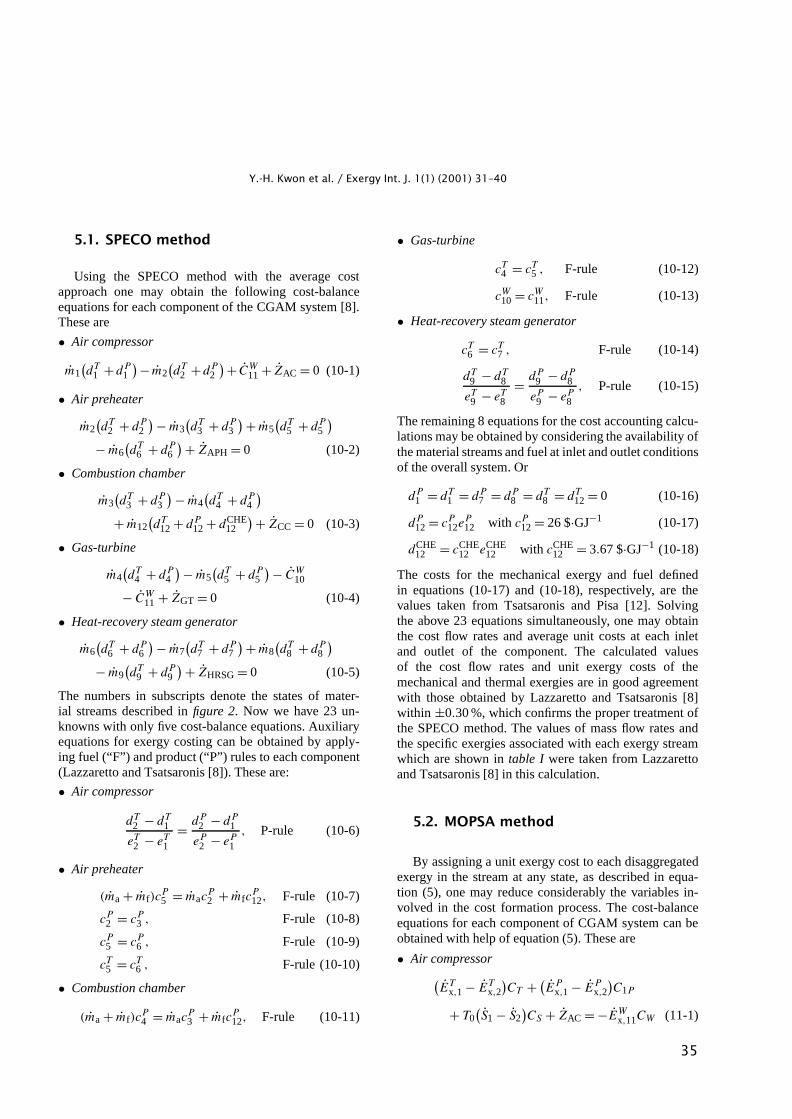
Using the SPECO method with the average costapproach one may obtain the following cost-balanceequations for each component of the CGAM system [8].These are
• Air compressor
m1(dT
1 +dP1
)− m2(dT
2 +dP2
)+ CW11 + ZAC = 0 (10-1)
• Air preheater
m2(dT
2 + dP2
) − m3(dT
3 + dP3
) + m5(dT
5 + dP5
)− m6
(dT
6 + dP6
) + ZAPH = 0 (10-2)
• Combustion chamber
m3(dT
3 + dP3
) − m4(dT
4 + dP4
)+ m12
(dT
12 + dP12 + dCHE
12
) + ZCC = 0 (10-3)
• Gas-turbine
m4(dT
4 + dP4
) − m5(dT
5 + dP5
) − CW10
− CW11 + ZGT = 0 (10-4)
• Heat-recovery steam generator
m6(dT
6 + dP6
) − m7(dT
7 + dP7
) + m8(dT
8 + dP8
)− m9
(dT
9 + dP9
) + ZHRSG = 0 (10-5)
The numbers in subscripts denote the states of mater-ial streams described in figure 2. Now we have 23 un-knowns with only five cost-balance equations. Auxiliaryequations for exergy costing can be obtained by apply-ing fuel (“F”) and product (“P”) rules to each component(Lazzaretto and Tsatsaronis [8]). These are:
• Air compressor
dT2 − dT
1
eT2 − eT
1
= dP2 − dP
1
eP2 − eP
1
, P-rule (10-6)
• Air preheater
(ma + mf)cP5 = mac
P2 + mfc
P12, F-rule (10-7)
cP2 = cP
3 , F-rule (10-8)
cP5 = cP
6 , F-rule (10-9)
cT5 = cT
6 , F-rule (10-10)
• Combustion chamber
(ma + mf)cP4 = mac
P3 + mfc
P12, F-rule (10-11)
• Gas-turbine
cT4 = cT
5 , F-rule (10-12)
cW10 = cW
11, F-rule (10-13)
• Heat-recovery steam generator
cT6 = cT
7 , F-rule (10-14)
dT9 − dT
8
eT9 − eT
8
= dP9 − dP
8
eP9 − eP
8
, P-rule (10-15)
The remaining 8 equations for the cost accounting calcu-lations may be obtained by considering the availability ofthe material streams and fuel at inlet and outlet conditionsof the overall system. Or
dP1 = dT
1 = dP7 = dP
8 = dT8 = dT
12 = 0 (10-16)
dP12 = cP
12eP12 with cP
12 = 26 $·GJ−1 (10-17)
dCHE12 = cCHE
12 eCHE12 with cCHE
12 = 3.67 $·GJ−1 (10-18)
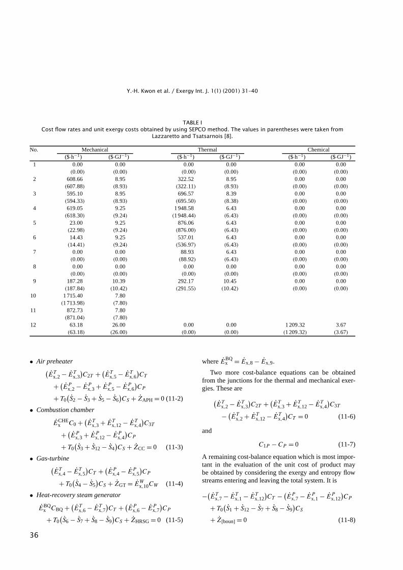
The costs for the mechanical exergy and fuel definedin equations (10-17) and (10-18), respectively, are thevalues taken from Tsatsaronis and Pisa [12]. Solvingthe above 23 equations simultaneously, one may obtainthe cost flow rates and average unit costs at each inletand outlet of the component. The calculated valuesof the cost flow rates and unit exergy costs of themechanical and thermal exergies are in good agreementwith those obtained by Lazzaretto and Tsatsaronis [8]within ±0.30 %, which confirms the proper treatment ofthe SPECO method. The values of mass flow rates andthe specific exergies associated with each exergy streamwhich are shown in table I were taken from Lazzarettoand Tsatsaronis [8] in this calculation.
5.2. MOPSA method
By assigning a unit exergy cost to each disaggregatedexergy in the stream at any state, as described in equa-tion (5), one may reduce considerably the variables in-volved in the cost formation process. The cost-balanceequations for each component of CGAM system can beobtained with help of equation (5). These are
• Air compressor(ET
x,1 − ETx,2
)CT + (
EPx,1 − EP
x,2
)C1P
+ T0(S1 − S2
)CS + ZAC = −EW
x,11CW (11-1)
35
Y.-H. Kwon et al. / Exergy Int. J. 1(1) (2001) 31–40
TABLE ICost flow rates and unit exergy costs obtained by using SEPCO method. The values in parentheses were taken from
Lazzaretto and Tsatsarnois [8].
No. Mechanical Thermal Chemical($·h−1) ($·GJ−1) ($·h−1) ($·GJ−1) ($·h−1) ($·GJ−1)
1 0.00 0.00 0.00 0.00 0.00 0.00(0.00) (0.00) (0.00) (0.00) (0.00) (0.00)
2 608.66 8.95 322.52 8.95 0.00 0.00(607.88) (8.93) (322.11) (8.93) (0.00) (0.00)
3 595.10 8.95 696.57 8.39 0.00 0.00(594.33) (8.93) (695.50) (8.38) (0.00) (0.00)
4 619.05 9.25 1 948.58 6.43 0.00 0.00(618.30) (9.24) (1 948.44) (6.43) (0.00) (0.00)
5 23.00 9.25 876.06 6.43 0.00 0.00(22.98) (9.24) (876.00) (6.43) (0.00) (0.00)
6 14.43 9.25 537.01 6.43 0.00 0.00(14.41) (9.24) (536.97) (6.43) (0.00) (0.00)
7 0.00 0.00 88.93 6.43 0.00 0.00(0.00) (0.00) (88.92) (6.43) (0.00) (0.00)
8 0.00 0.00 0.00 0.00 0.00 0.00(0.00) (0.00) (0.00) (0.00) (0.00) (0.00)
9 187.28 10.39 292.17 10.45 0.00 0.00(187.84) (10.42) (291.55) (10.42) (0.00) (0.00)
10 1 715.40 7.80(1 713.98) (7.80)
11 872.73 7.80(871.04) (7.80)
12 63.18 26.00 0.00 0.00 1 209.32 3.67(63.18) (26.00) (0.00) (0.00) (1 209.32) (3.67)
• Air preheater(ET
x,2 − ETx,3
)C2T + (
ETx,5 − ET
x,6
)CT
+ (EP
x,2 − EPx,3 + EP
x,5 − EPx,6
)CP
+ T0(S2 − S3 + S5 − S6
)CS + ZAPH = 0 (11-2)
• Combustion chamber
ECHEx C0 + (
ETx,3 + ET
x,12 − ETx,4
)C3T
+ (EP
x,3 + EPx,12 − EP
x,4
)CP
+ T0(S3 + S12 − S4
)CS + ZCC = 0 (11-3)
• Gas-turbine(ET
x,4 − ETx,5
)CT + (
EPx,4 − EP
x,5
)CP
+ T0(S4 − S5
)CS + ZGT = EW
x,10CW (11-4)
• Heat-recovery steam generator
EBQx CBQ + (
ETx,6 − ET
x,7
)CT + (
EPx,6 − EP
x,7
)CP
+ T0(S6 − S7 + S8 − S9
)CS + ZHRSG = 0 (11-5)
where EBQx = Ex,8 − Ex,9.
Two more cost-balance equations can be obtainedfrom the junctions for the thermal and mechanical exer-gies. These are
(ET
x,2 − ETx,3
)C2T + (
ETx,3 + ET
x,12 − ETx,4
)C3T
− (ET
x,2 + ETx,12 − ET
x,4
)CT = 0 (11-6)
and
C1P − CP = 0 (11-7)
A remaining cost-balance equation which is most impor-tant in the evaluation of the unit cost of product maybe obtained by considering the exergy and entropy flowstreams entering and leaving the total system. It is
−(ET
x,7 − ETx,1 − ET
x,12
)CT − (
EPx,7 − EP
x,1 − EPx,12
)CP
+ T0(S1 + S12 − S7 + S8 − S9
)CS
+ Z[boun] = 0 (11-8)
36
Y.-H. Kwon et al. / Exergy Int. J. 1(1) (2001) 31–40
TABLE IIThe unit cost of electricity and steam obtained fromSPECO and MOPSA methods for the CGAM system with
HRSG and without HRSG.
Calculation methods SPECO MOPSA equation (12)of unit costUnit cost of without HRSG 7.80 12.91 12.90electricity($·GJ−1)
with HRSG 7.80 8.48
Unit cost ofsteam ($·GJ−1)
10.45 10.79
The term (ETx,7 − ET
x,1 − ETx,12) in equation (11-8) is just
escaping thermal exergy from the system and −T0(S1 +S12 − S7 + S8 − S9) is the entropy generation inside thesystem. Now one may obtain the unit cost of productsCW and CBQ by solving the foregoing 8 equationssimultaneously given fuel cost of C0.
The production costs obtained from both SPECO andMOPSA methods for the CGAM system are shown intable II. The unit cost of electricity for the gas-turbinesystem without HRSG may be obtained by using thefollowing equation [13], which is also listed in thetable II:
CW = C0
ηe
[1 +
∑Zk
C0ECHEx
](12)
The relative deviations in the production costs evalu-ated from SPECO and MOPSA methods lie between 6and 11 %. The unit costs of electricity and steam for theCGAM system are lower when SPECO method is used.The electricity cost obtained from equation (12) is closeto the value by MOPSA method for the CGAM system.In the SPECO methodology, the cost formation processof electricity is not changed even though HRSG is ab-sent. However, the unit cost of electricity from MOPSAmethod increases very much since the escaping thermalexergy from the system drastically increases when HRSGis absent.
6. RESULTS AND DISCUSSION
In table III, the initial investments, the monetary flowrate which includes all investment, operating and main-tenance costs and the percentage of the annuity cost foreach component to the total annuity of the 1 000 kW gas-turbine cogeneration system are given. The unit exergycost of products and the corresponding monetary flowrates given fuel exergy costs, C0 = 5.82·10−6 $·kJ−1
have been obtained. The salvage value after 15 years was
TABLE IIIInitial investment for each component in the 1000 kW
gas-turbine cogeneration system.
Component Initial Monetary Relativeinvestment flow rate annuity
($) ($·year−1) (%)Combustor 80 000 10 266 9.25Compressor 150 000 19 249 17.34Turbine 350 000 44 914 40.46Inter-cooler 20 000 2 567 2.31Waste heat boiler 150 000 19 249 17.34Fuel gas compressor 95 000 12 191 10.99Chimney 20 000 2 567 2.31
Total 865 000 111 003 100.00
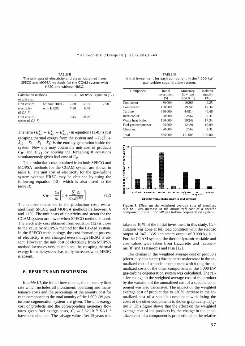
Figure 3. Effect on the weighted average cost of productsdue to 130% increase in the annualized cost of a specificcomponent in the 1000 kW gas turbine cogeneration system.
taken as 10 % of the initial investment in this study. Cal-culation was done at full load condition with the electricoutput of 947.1 kW and steam output of 3 000 kg·h−1.For the CGAM system, the thermodynamic variable andcost values were taken from Lazzaretto and Tsatsaro-nis [8] and Tsatsaronis and Pisa [12].
The change in the weighted average cost of products(electricity plus steam) due to increase/decrease in the an-nualized cost of a specific component with fixing the an-nualized costs of the other components in the 1 000 kWgas-turbine cogeneration system was calculated. The rel-ative change in the weighted average cost of the productby the variation of the annualized cost of a specific com-ponent was also calculated. The impact on the weightedaverage cost of product due to 130 % increase in the an-nualized cost of a specific component with fixing thecosts of the other components is shown graphically in fig-ure 3. This figure shows that the effect on the weightedaverage cost of the products by the change in the annu-alized cost of a component is proportional to the relative
37
Y.-H. Kwon et al. / Exergy Int. J. 1(1) (2001) 31–40
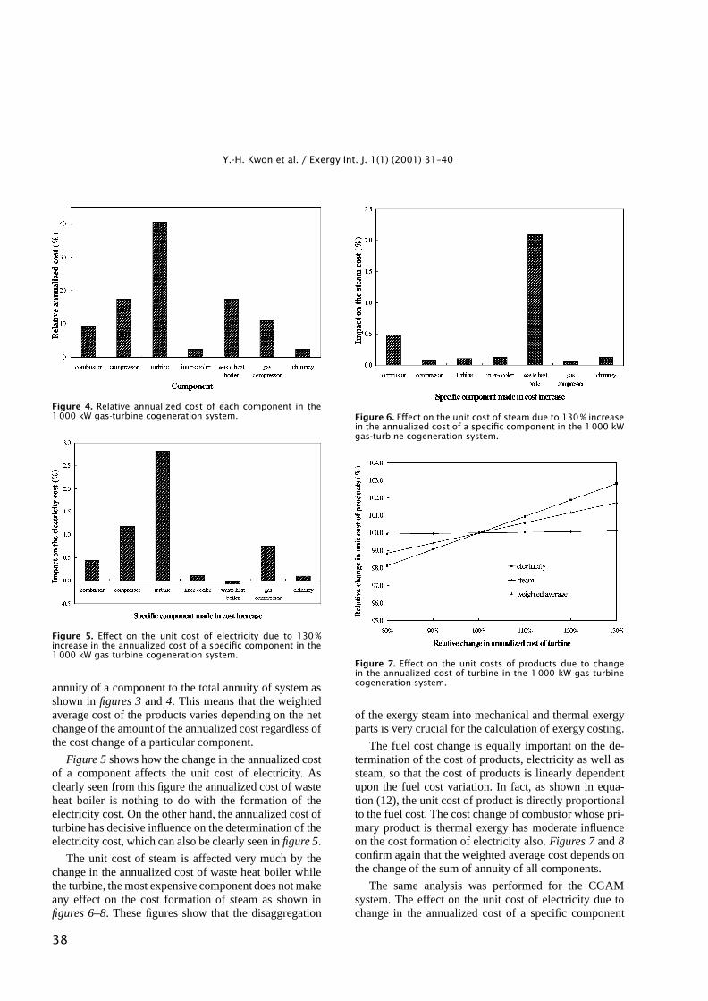
Figure 4. Relative annualized cost of each component in the1000 kW gas-turbine cogeneration system.
Figure 5. Effect on the unit cost of electricity due to 130%increase in the annualized cost of a specific component in the1000 kW gas turbine cogeneration system.
annuity of a component to the total annuity of system asshown in figures 3 and 4. This means that the weightedaverage cost of the products varies depending on the netchange of the amount of the annualized cost regardless ofthe cost change of a particular component.
Figure 5 shows how the change in the annualized costof a component affects the unit cost of electricity. Asclearly seen from this figure the annualized cost of wasteheat boiler is nothing to do with the formation of theelectricity cost. On the other hand, the annualized cost ofturbine has decisive influence on the determination of theelectricity cost, which can also be clearly seen in figure 5.
The unit cost of steam is affected very much by thechange in the annualized cost of waste heat boiler whilethe turbine, the most expensive component does not makeany effect on the cost formation of steam as shown infigures 6–8. These figures show that the disaggregation
Figure 6. Effect on the unit cost of steam due to 130% increasein the annualized cost of a specific component in the 1000 kWgas-turbine cogeneration system.
Figure 7. Effect on the unit costs of products due to changein the annualized cost of turbine in the 1000 kW gas turbinecogeneration system.
of the exergy steam into mechanical and thermal exergyparts is very crucial for the calculation of exergy costing.
The fuel cost change is equally important on the de-termination of the cost of products, electricity as well assteam, so that the cost of products is linearly dependentupon the fuel cost variation. In fact, as shown in equa-tion (12), the unit cost of product is directly proportionalto the fuel cost. The cost change of combustor whose pri-mary product is thermal exergy has moderate influenceon the cost formation of electricity also. Figures 7 and 8confirm again that the weighted average cost depends onthe change of the sum of annuity of all components.
The same analysis was performed for the CGAMsystem. The effect on the unit cost of electricity due tochange in the annualized cost of a specific component
38
Y.-H. Kwon et al. / Exergy Int. J. 1(1) (2001) 31–40
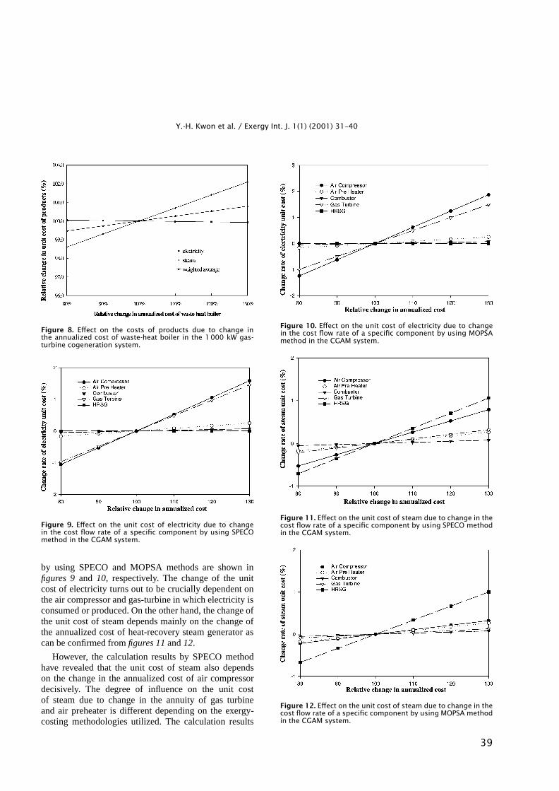
Figure 8. Effect on the costs of products due to change inthe annualized cost of waste-heat boiler in the 1000 kW gas-turbine cogeneration system.
Figure 9. Effect on the unit cost of electricity due to changein the cost flow rate of a specific component by using SPECOmethod in the CGAM system.
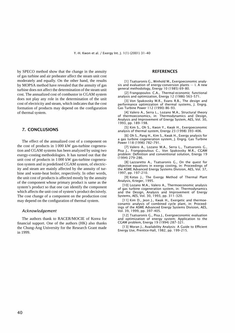
by using SPECO and MOPSA methods are shown infigures 9 and 10, respectively. The change of the unitcost of electricity turns out to be crucially dependent onthe air compressor and gas-turbine in which electricity isconsumed or produced. On the other hand, the change ofthe unit cost of steam depends mainly on the change ofthe annualized cost of heat-recovery steam generator ascan be confirmed from figures 11 and 12.
However, the calculation results by SPECO methodhave revealed that the unit cost of steam also dependson the change in the annualized cost of air compressordecisively. The degree of influence on the unit costof steam due to change in the annuity of gas turbineand air preheater is different depending on the exergy-costing methodologies utilized. The calculation results
Figure 10. Effect on the unit cost of electricity due to changein the cost flow rate of a specific component by using MOPSAmethod in the CGAM system.
Figure 11. Effect on the unit cost of steam due to change in thecost flow rate of a specific component by using SPECO methodin the CGAM system.
Figure 12. Effect on the unit cost of steam due to change in thecost flow rate of a specific component by using MOPSA methodin the CGAM system.
39
Y.-H. Kwon et al. / Exergy Int. J. 1(1) (2001) 31–40
by SPECO method show that the change in the annuityof gas turbine and air preheater affect the steam unit costmoderately and equally. On the other hand, the resultsby MOPSA method have revealed that the annuity of gasturbine does not affect the determination of the steam unitcost. The annualized cost of combustor in CGAM systemdoes not play any role in the determination of the unitcost of electricity and steam, which indicates that the costformation of products may depend on the configurationof thermal system.
7. CONCLUSIONS
The effect of the annualized cost of a component onthe cost of products in 1 000 kW gas-turbine cogenera-tion and CGAM systems has been analyzed by using twoexergy-costing methodologies. It has turned out that theunit cost of products in 1 000 kW gas-turbine cogenera-tion system and in predefined CGAM system, of electric-ity and steam are mainly affected by the annuity of tur-bine and waste-heat boiler, respectively. In other words,the unit cost of products is affected mostly by the annuityof the component whose primary product is same as thesystem’s product so that one can identify the componentwhich affects the unit cost of system’s product decisively.The cost change of a component on the production costmay depend on the configuration of thermal system.
Acknowledgement
The authors thank to RACER/MOCIE of Korea forfinancial support. One of the authors (HK) also thanksthe Chung-Ang University for the Research Grant madein 1999.
REFERENCES
[1] Tsatsaronis G., Winhold M., Exergoeconomic analy-sis and evaluation of energy-conversion plants — I. A newgeneral methodology, Energy 10 (1985) 69–80.
[2] Frangopoulos C.A., Thermal-economic functionalanalysis and optimization, Energy 12 (1986) 563–571.
[3] Von Spakovsky M.R., Evans R.B., The design andperformance optimization of thermal systems, J. Engrg.Gas Turbine Power 112 (1990) 86–93.
[4] Valero A., Serra L., Lozano M.A., Structural theoryof thermoeconomics, in: Thermodynamics and Design,Analysis and Improvement of Energy System, AES, Vol. 30,1993, pp. 189–198.
[5] Kim S., Oh S., Kwon Y., Kwak H., Exergoeconomicanalysis of thermal system, Energy 23 (1998) 393–406.
[6] Oh S., Pang H., Kim S., Kwak H., Exergy analysis fora gas turbine cogeneration system, J. Engrg. Gas TurbinePower 118 (1996) 782–791.
[7] Valero A., Lozano M.A., Serra L., Tsatsaronis G.,Pisa J., Frangopoulous C., Von Spakovsky M.R., CGAMproblem: Definition and conventional solution, Energy 19(1994) 279–286.
[8] Lazzaretto A., Tsatsaronis G., On the quest forobjective equations in exergy costing, in: Proceedings ofthe ASME Advanced Energy Systems Division, AES, Vol. 37,1997, pp. 197–210.
[9] Kotas J., The Exergy Method of Thermal PlantAnalysis, Krieger, 1995.
[10] Lozano M.A., Valero A., Thermoeconomic analysisof gas turbine cogeneration system, in: Thermodynamicsand the Design, Analysis and Improvement of EnergySystems, AES, Vol. 30, 1993, pp. 311–320.
[11] Kim D., Jeon J., Kwak H., Exergetic and thermoe-conamic analysis of combined cycle plant, in: Proceed-ings of the ASME Advanced Energy Systems Division, AES,Vol. 39, 1999, pp. 397–405.
[12] Tsatsaronis G., Pisa J., Exergoeconomic evaluationand optimization of energy system; Application to theCGAM problem, Energy 19 (1994) 287–321.
[13] Moran J., Availability Analysis: A Guide to EfficientEnergy Use, Prentice-Hall, 1982, pp. 199–215.
40