Embed Size (px)
Citation preview
8-1
Exercise 8
Closed-Loop Pressure Control,
Proportional-Plus-Integral Mode
EXERCISE OBJECTIVE
To understand open and closed-loop pressure control;To learn how to sense the pressure in a pneumatic circuit;To control the pressure in a closed-loop mode.
DISCUSSION
Pressure Control
Pressure control is normally used either to limit the pressure applied to a cylinderpiston or to maintain a specific level of pressure in a circuit branch.
In some applications, for example, it is necessary to limit the pressure applied tothe cylinder piston to prevent distorting or crushing the workpieces;
In other applications, it is necessary to maintain the pressure applied to thecylinder piston at a specific level on successive cylinder cycles to exert a veryprecise force against the workpieces.
Control of cylinder pressure can be done either with a conventional pressureregulator, or with a servo control valve of the pressure type (electropneumaticpressure regulator). However, a servo control valve of the pressure type can becontrolled remotely with a potentiometer on an operator’s panel. Moreover, the servocontrol valve allows precise adjustment of the pressure level.
As with position control, pressure control can be accomplished by using either anopen-loop or a closed-loop system.
With the open-loop system, the pressure is controlled by a setpoint only, and theactual pressure is not taken into account. This type of system cannot provide andmaintain accurate pressure control.
With the closed-loop system, the pressure is controlled with a controller and afeedback loop. Most systems of pressure control are closed-loop because theyprovide accurate control of pressure and they improve repeatability (the ability toprovide the same output every time for a same input), for a given setpoint voltage.
Closed-Loop Pressure Control,
Proportional-Plus-Integral Mode
8-2
Closed-Loop Pressure Control Systems
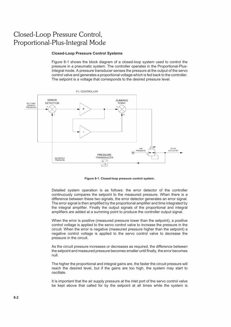
Figure 8-1 shows the block diagram of a closed-loop system used to control thepressure in a pneumatic system. The controller operates in the Proportional-Plus-Integral mode. A pressure transducer senses the pressure at the output of the servocontrol valve and generates a proportional voltage which is fed back to the controller.The setpoint is a voltage that corresponds to the desired pressure level.
Figure 8-1. Closed-loop pressure control system.
Detailed system operation is as follows: the error detector of the controllercontinuously compares the setpoint to the measured pressure. When there is adifference between these two signals, the error detector generates an error signal.The error signal is then amplified by the proportional amplifier and time integrated bythe integral amplifier. Finally the output signals of the proportional and integralamplifiers are added at a summing point to produce the controller output signal.
When the error is positive (measured pressure lower than the setpoint), a positivecontrol voltage is applied to the servo control valve to increase the pressure in thecircuit. When the error is negative (measured pressure higher than the setpoint) anegative control voltage is applied to the servo control valve to decrease thepressure in the circuit.
As the circuit pressure increases or decreases as required, the difference betweenthe setpoint and measured pressure becomes smaller until finally, the error becomesnull.
The higher the proportional and integral gains are, the faster the circuit pressure willreach the desired level, but if the gains are too high, the system may start tooscillate.
It is important that the air supply pressure at the inlet port of the servo control valvebe kept above that called for by the setpoint at all times while the system is
Closed-Loop Pressure Control,
Proportional-Plus-Integral Mode
8-3
functioning. Otherwise, the servo control valve will not be able to bring or maintainthe pressure at setpoint.
Pressure Transducer
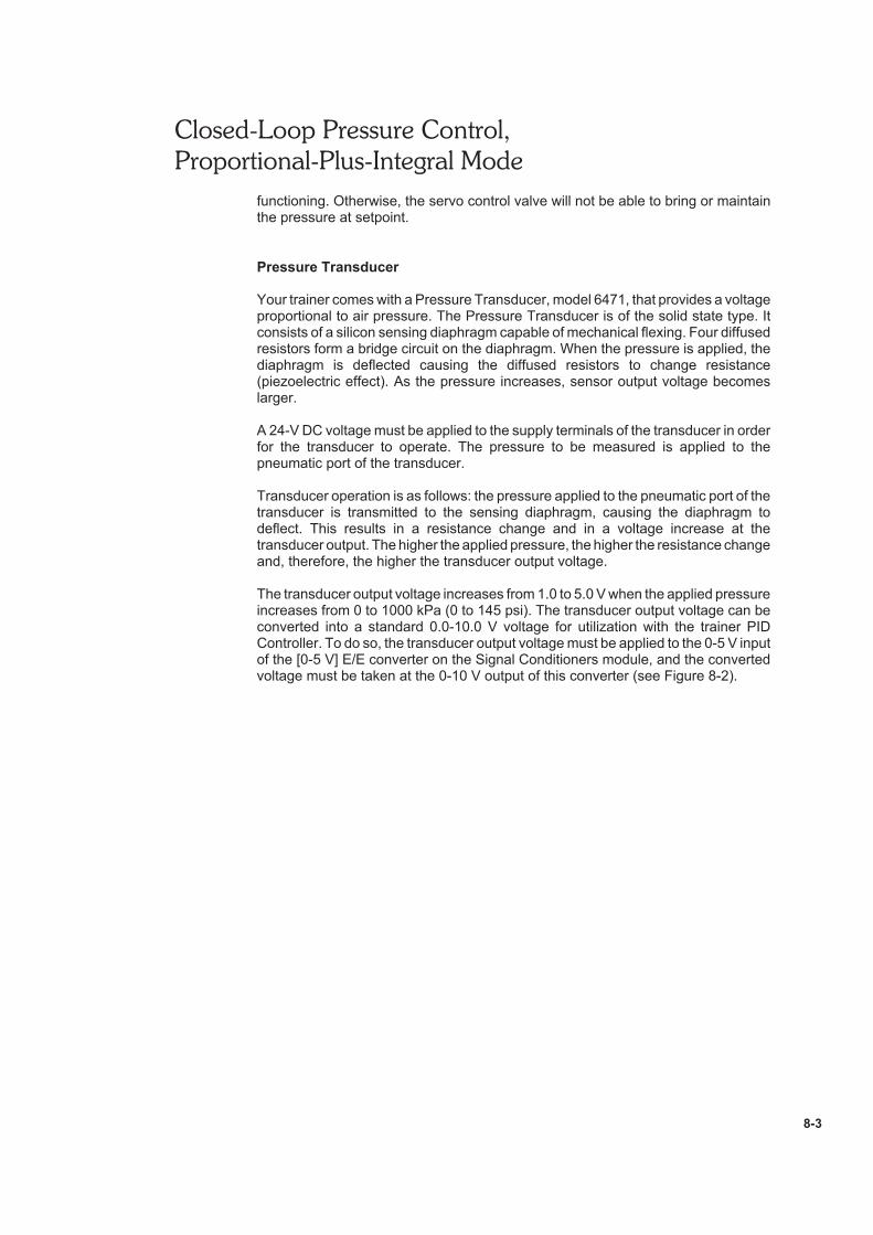
Your trainer comes with a Pressure Transducer, model 6471, that provides a voltageproportional to air pressure. The Pressure Transducer is of the solid state type. Itconsists of a silicon sensing diaphragm capable of mechanical flexing. Four diffusedresistors form a bridge circuit on the diaphragm. When the pressure is applied, thediaphragm is deflected causing the diffused resistors to change resistance(piezoelectric effect). As the pressure increases, sensor output voltage becomeslarger.
A 24-V DC voltage must be applied to the supply terminals of the transducer in orderfor the transducer to operate. The pressure to be measured is applied to thepneumatic port of the transducer.
Transducer operation is as follows: the pressure applied to the pneumatic port of thetransducer is transmitted to the sensing diaphragm, causing the diaphragm todeflect. This results in a resistance change and in a voltage increase at thetransducer output. The higher the applied pressure, the higher the resistance changeand, therefore, the higher the transducer output voltage.
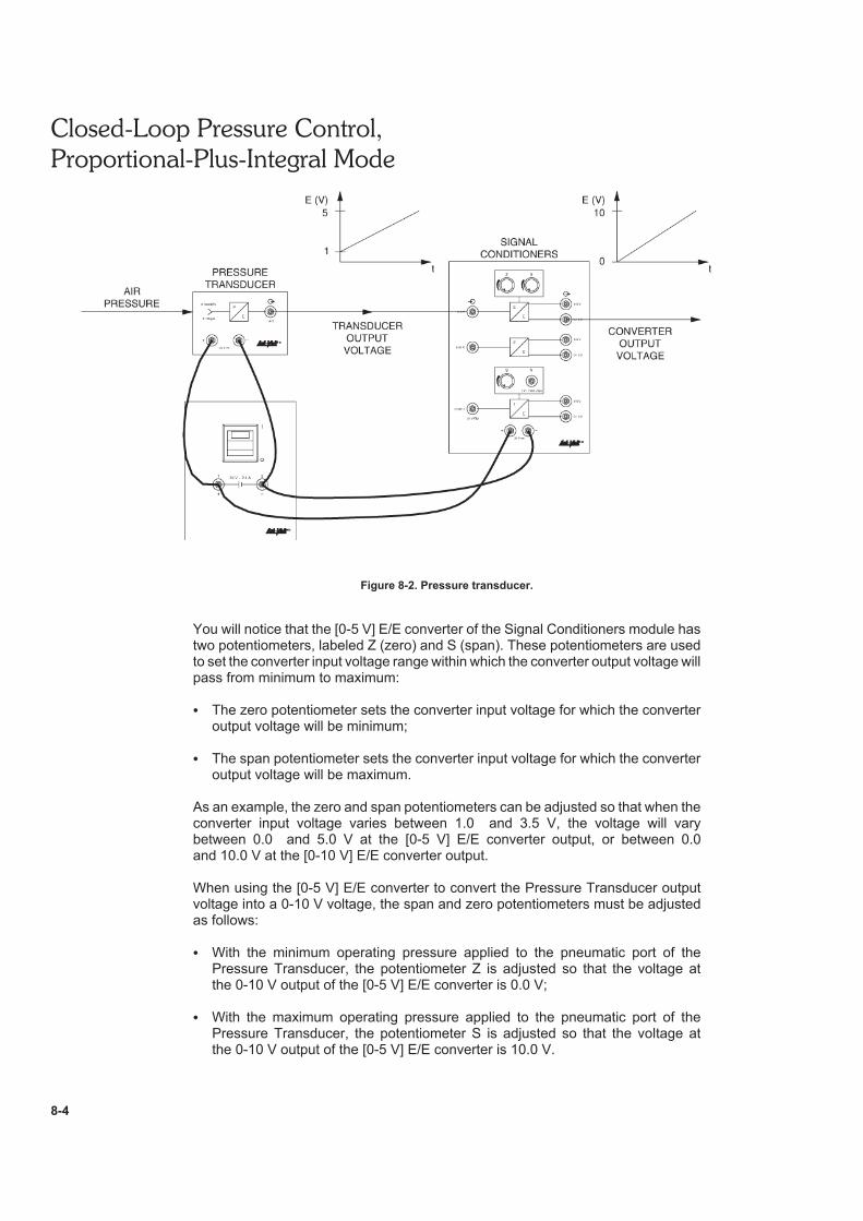
The transducer output voltage increases from 1.0 to 5.0 V when the applied pressureincreases from 0 to 1000 kPa (0 to 145 psi). The transducer output voltage can beconverted into a standard 0.0-10.0 V voltage for utilization with the trainer PIDController. To do so, the transducer output voltage must be applied to the 0-5 V inputof the [0-5 V] E/E converter on the Signal Conditioners module, and the convertedvoltage must be taken at the 0-10 V output of this converter (see Figure 8-2).
Closed-Loop Pressure Control,
Proportional-Plus-Integral Mode
8-4
Figure 8-2. Pressure transducer.
You will notice that the [0-5 V] E/E converter of the Signal Conditioners module hastwo potentiometers, labeled Z (zero) and S (span). These potentiometers are usedto set the converter input voltage range within which the converter output voltage willpass from minimum to maximum:
The zero potentiometer sets the converter input voltage for which the converteroutput voltage will be minimum;
The span potentiometer sets the converter input voltage for which the converteroutput voltage will be maximum.
As an example, the zero and span potentiometers can be adjusted so that when theconverter input voltage varies between 1.0 and 3.5 V, the voltage will varybetween 0.0 and 5.0 V at the [0-5 V] E/E converter output, or between 0.0and 10.0 V at the [0-10 V] E/E converter output.
When using the [0-5 V] E/E converter to convert the Pressure Transducer outputvoltage into a 0-10 V voltage, the span and zero potentiometers must be adjustedas follows:
With the minimum operating pressure applied to the pneumatic port of thePressure Transducer, the potentiometer Z is adjusted so that the voltage atthe 0-10 V output of the [0-5 V] E/E converter is 0.0 V;
With the maximum operating pressure applied to the pneumatic port of thePressure Transducer, the potentiometer S is adjusted so that the voltage atthe 0-10 V output of the [0-5 V] E/E converter is 10.0 V.
Closed-Loop Pressure Control,
Proportional-Plus-Integral Mode
8-5
Procedure summary
In the first part of the exercise, Open-Loop Pressure Control, you will observe therelationship between flow and pressure in open-loop control.
In the second part of the exercise, Sensing the Pressure Using the Trainer PressureTransducer, you will learn how to sense the pressure in a circuit using a pressuretransducer.
In the third part of the exercise, Closed-Loop Pressure Control, you will performclosed-loop pressure control. You will observe the relationship between flow andpressure in closed-loop control.
In the last part of the exercise, System Repeatability, you will determine if the closed-loop system is able to arrive at the same pressure level on successive cycles for agiven setpoint voltage.
EQUIPMENT REQUIRED
Refer to the Equipment Utilization Chart, in Appendix A of the manual, to obtain thelist of equipment required to perform this exercise.
PROCEDURE
Open-Loop Pressure Control
Setting up the system
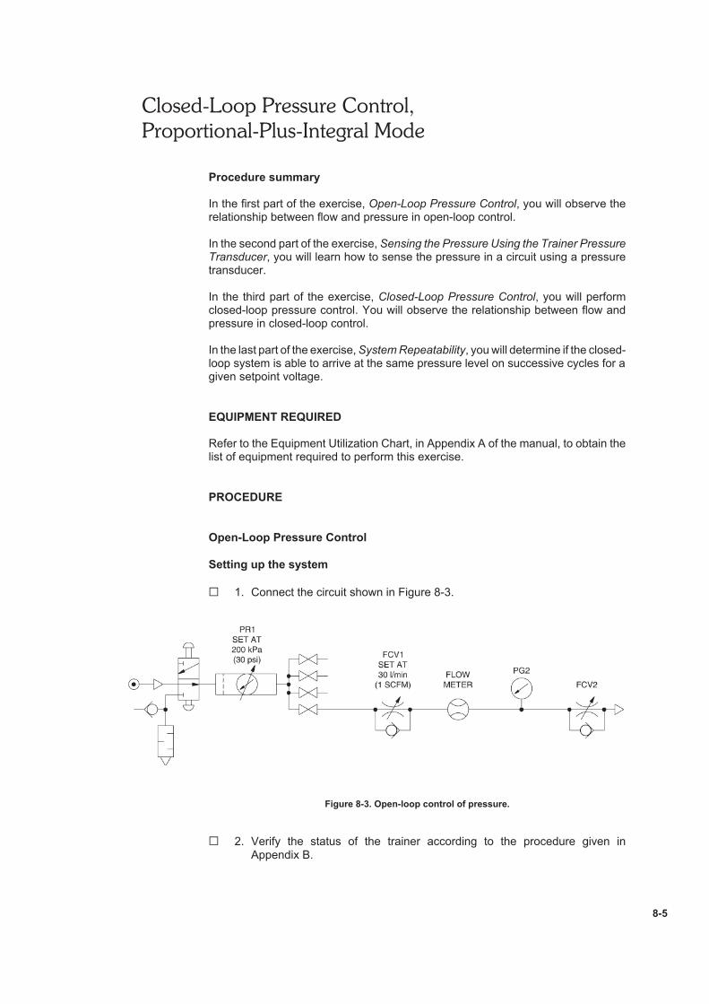
G 1. Connect the circuit shown in Figure 8-3.
Figure 8-3. Open-loop control of pressure.
G 2. Verify the status of the trainer according to the procedure given inAppendix B.
Closed-Loop Pressure Control,
Proportional-Plus-Integral Mode
8-6
G 3. Close the Flow Control Valve FCV1 by turning the control knob fullyclockwise, and open the Flow Control Valve FCV2 by turning the controlknob fully counterclockwise.
G 4. On the Conditioning Unit, open the main shutoff valve and the requiredbranch shutoff valve at the manifold.
Set the main pressure regulator to obtain 140 kPa (20 psi) on the regulatedpressure gauge.
G 5. Set the Flow Control Valve FCV1 to obtain 30 l/min (1 SCFM) on theFlowmeter.
Readjust the setting of the main pressure regulator and Flow Control ValveFCV1 to obtain exactly 140 kPa (20 psi) and 30 l/min (1 SCFM).
Note: The Flow Control Valve FCV1 is set at 30 l/min (1 SCFM)in order to correspond to the flow characteristics of the ServoControl Valve which will be used later in the exercise.
G 6. Close Flow Control Valve FCV2 by turning the control knob fully clockwise.
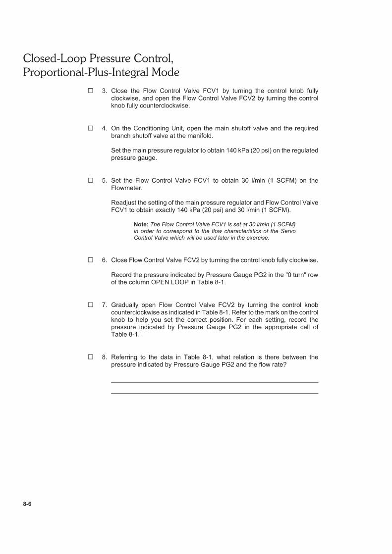
Record the pressure indicated by Pressure Gauge PG2 in the "0 turn" rowof the column OPEN LOOP in Table 8-1.
G 7. Gradually open Flow Control Valve FCV2 by turning the control knobcounterclockwise as indicated in Table 8-1. Refer to the mark on the controlknob to help you set the correct position. For each setting, record thepressure indicated by Pressure Gauge PG2 in the appropriate cell ofTable 8-1.
G 8. Referring to the data in Table 8-1, what relation is there between thepressure indicated by Pressure Gauge PG2 and the flow rate?
Closed-Loop Pressure Control,
Proportional-Plus-Integral Mode
8-7
FLOW CONTROL
VALVE OPENING
(FCV2)
PRESSURE CONTROL
VOLTAGE IN THE
CLOSED-LOOP
MODEOPEN-LOOP CLOSED-LOOP
0 turn
1 turn
2 turns
3 turns
4 turns
5 turns
6 turns
7 turns
8 turns
9 turns
10 turns
Table 8-1. Comparison between open-loop and closed-loop pressure control.
G 9. Do your observations confirm that the open-loop pressure control makes itpossible to maintain the pressure constant when the flow rate varies?
G Yes G No
G 10. On the Conditioning Unit, close the main shutoff valve.
Sensing the Pressure Using the Trainer Pressure Transducer
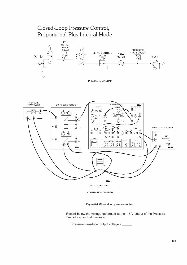
G 11. Connect the circuit shown in Figure 8-4.
Note: Do not connect the 0-10 V output of the [0-5 V] E/Econverter of the Signal Conditioners module to the negative inputof the ERROR DETECTOR of the PID Controller at this time.
Also, do not connect the integral amplifier output to the summingpoint of the PID Controller at this time.
G 12. Make the following settings on the PID Controller:
PROPORTIONAL (P) GAIN range . . . . . . . . . . . . . . . . . . . . . . LOWPROPORTIONAL (P) GAIN . . . . . . . . . . . . . . . . . . . . . . . . . . . . MIN.
Closed-Loop Pressure Control,
Proportional-Plus-Integral Mode
8-8
G 13. Turn on the DC Power Supply and PID Controller. Do not open the mainshutoff valve on the Conditioning Unit at this time.
G 14. On the PID Controller, set the SETPOINT potentiometer 1 to obtain 10.0 Vat the SETPOINT output 1.
Set the PROPORTIONAL GAIN to obtain 12.0 V approximately at theLIMITER input.
Set the UPPER LIMIT potentiometer to obtain 10.0 V at the LIMITER output.
Set the SETPOINT potentiometers 1 and 2 to obtain 0.0 V at the SETPOINToutput 1, then select SETPOINT potentiometer 1.
Set the PROPORTIONAL GAIN at ½ of MAX.
G 15. On the Signal Conditioners module, set the Z (zero) and S (span)potentiometers of the [0-5 V] E/E converter as follows:
Zero (Z) . . . . . . . . . . . . . . . . . . . . . . . . . . . . . . . . . . . . fully clockwiseSpan (S) . . . . . . . . . . . . . . . . . . . . . . . . . . . . . fully counterclockwise
G 16. Close Flow Control Valve FCV2 by turning the control knob fully clockwise.
G 17. On the Conditioning Unit, open the main shutoff valve.
Set the main pressure regulator to obtain 630 kPa (90 psi) on the regulatedpressure gauge.
G 18. Connect a DC voltmeter to the 1-5 V output of the Pressure Transducer.
With a setpoint value of 0.0 V, the pressure indicated by the PressureTransducer display should be approximately 0 kPa (0 psi). Is this yourobservation?
G Yes G No
Note: If the pressure units indicated at the bottom of the PressureTransducer display do not correspond to your unit system, referto Appendix D to modify the setting of the Pressure Transducer.
Closed-Loop Pressure Control,
Proportional-Plus-Integral Mode
8-9
Figure 8-4. Closed-loop pressure control.
Record below the voltage generated at the 1-5 V output of the PressureTransducer for that pressure.
Pressure transducer output voltage =
Closed-Loop Pressure Control,
Proportional-Plus-Integral Mode
8-10
G 19. Connect the DC voltmeter at the 0-10 V output of the [0-5 V] E/E converteron the Signal Conditioners module.
While observing the voltmeter reading, slowly turn the knob of thepotentiometer Z (zero) of the [0-5 V] E/E converter counterclockwise andstop turning as soon as the voltage reaches 0.0 V.
G 20. Increase the system pressure by increasing the SETPOINT potentiometer 1value to obtain 350 kPa (50 psi) on the Pressure Transducer display.Observe that this causes the voltage at the 1-5 V output of the PressureTransducer to increase.
Record below the voltage generated at the 1-5 V output of the PressureTransducer for that pressure.
Pressure transducer output voltage =
G 21. With the DC voltmeter connected to the 0-10 V output of the [0-5 V] E/Econverter on the Signal Conditioners module, set the potentiometer S (span)of this converter to obtain 10.0 V on the voltmeter display.
Closed-Loop Pressure Control
G 22. Make the following settings on the PID Controller:
PROPORTIONAL (P) GAIN range . . . . . . . . . . . . . . . . . . . . . . . LOWPROPORTIONAL (P) GAIN . . . . . . . . . . . . . . . . . . . . . . . a of MAX.INTEGRAL (I) GAIN . . . . . . . . . . . . . . . . . . . . . . . . . . . . . ½ of MAX.INTEGRATOR ANTI-RESET . . . . . . . . . . . . . . . . . . . . . . . . . . . . . . I
G 23. Place the system in the closed-loop mode. To do so, connect the 0-10 Voutput of the [0-5 V] E/E converter on the Signal Conditioners module to thenegative input of the ERROR DETECTOR.
G 24. On the P.I.D. Controller, connect the integral amplifier output to thesumming point.
Set the SETPOINT potentiometer 1 to obtain 140 kPa (20 psi) on thePressure Transducer display.
Record the pressure value in the "0 turn" row of the column CLOSED-LOOP. Record also the voltage control at the 0-10 V input of the Servo
Control Valve in the appropriate cell in Table 8-1.
G 25. Gradually open Flow Control Valve FCV2 by turning the control knobcounterclockwise as indicated in Table 8-1. For each setting, record thepressure indicated on the Pressure Transducer display and the voltage
Closed-Loop Pressure Control,
Proportional-Plus-Integral Mode
8-11
control at the 0-10 V input of the Servo Control Valve in the appropriate cellsin Table 8-1.
Note: Reduce the PROPORTIONAL GAIN and/or INTEGRALGAIN if the system becomes unstable and starts to oscillate.
G 26. Compare the pressure values obtained in the closed-loop mode of controlto that obtained in the open-loop mode.
In the closed-loop mode, the pressure should be maintained constant formany turns of opening of the Flow Control Valve while it rapidly starts todecrease in the open-loop mode of control. Is this your observation?
G Yes G No
G 27. Referring to the data in Table 8-1, describe what happens to the controlvoltage of the Servo Control Valve as the opening of the Flow Control Valveincreases in the closed-loop mode of control.
System Repeatability
G 28. Close Flow Control Valve FCV2 by turning the control knob fully clockwise,then open the valve four turns.
G 29. Now test the repeatability of the system by alternately selecting theSETPOINT potentiometers 1 and 2 and watching the Pressure Transducerdisplay. Is the system capable of arriving at the same pressure level(140 kPa (20 psi)) on successive cycles? Explain.
G 30. Close Flow Control Valve FCV2 by turning the control knob fully clockwise.
On the P.I.D. Controller, select the SETPOINT potentiometer 1.
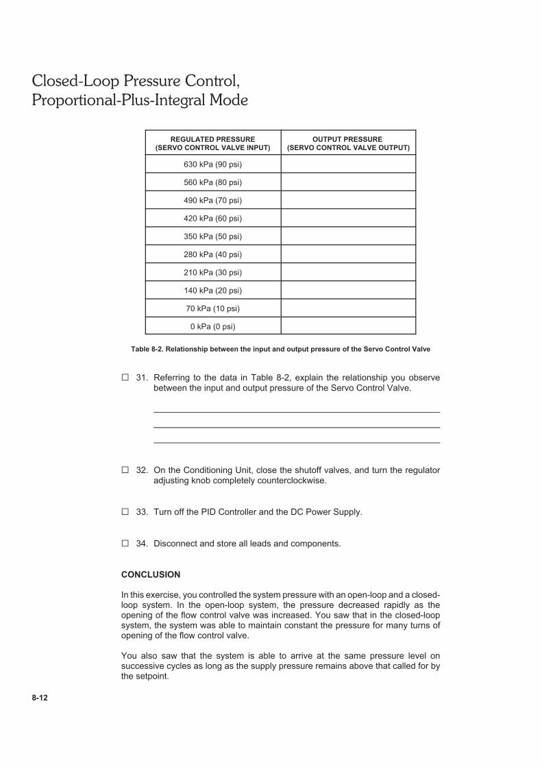
On the Conditioning Unit, use the main pressure regulator to decrease theregulated pressure by decrements of 70 kPa (10 psi) until it attains 0 kPa(0 psi). For each pressure setting, enter the pressure displayed by thePressure Transducer in Table 8-2.
Closed-Loop Pressure Control,
Proportional-Plus-Integral Mode
8-12
REGULATED PRESSURE
(SERVO CONTROL VALVE INPUT)
OUTPUT PRESSURE
(SERVO CONTROL VALVE OUTPUT)
630 kPa (90 psi)
560 kPa (80 psi)
490 kPa (70 psi)
420 kPa (60 psi)
350 kPa (50 psi)
280 kPa (40 psi)
210 kPa (30 psi)
140 kPa (20 psi)
70 kPa (10 psi)
0 kPa (0 psi)
Table 8-2. Relationship between the input and output pressure of the Servo Control Valve
G 31. Referring to the data in Table 8-2, explain the relationship you observebetween the input and output pressure of the Servo Control Valve.
G 32. On the Conditioning Unit, close the shutoff valves, and turn the regulatoradjusting knob completely counterclockwise.
G 33. Turn off the PID Controller and the DC Power Supply.
G 34. Disconnect and store all leads and components.
CONCLUSION
In this exercise, you controlled the system pressure with an open-loop and a closed-loop system. In the open-loop system, the pressure decreased rapidly as theopening of the flow control valve was increased. You saw that in the closed-loopsystem, the system was able to maintain constant the pressure for many turns ofopening of the flow control valve.
You also saw that the system is able to arrive at the same pressure level onsuccessive cycles as long as the supply pressure remains above that called for bythe setpoint.
Closed-Loop Pressure Control,
Proportional-Plus-Integral Mode
8-13
REVIEW QUESTIONS
1. What are the advantages of using a servo control valve of the pressure type tocontrol the pressure in a system?
2. What happens in a closed-loop pressure control system when a positive errorexists between the setpoint and measured pressure?
3. Explain why it is important that the supply pressure at the inlet port of the servocontrol valve be kept above that called for by the setpoint at all times while thesystem is functioning.
4. Briefly describe the operation of the trainer Pressure Transducer.