Embed Size (px)
Citation preview
1
UN
ITS
PROPORTIONAL PRECISION PRESSURE REGULATOR REGTRONIC SERIES
2
UN
ITS
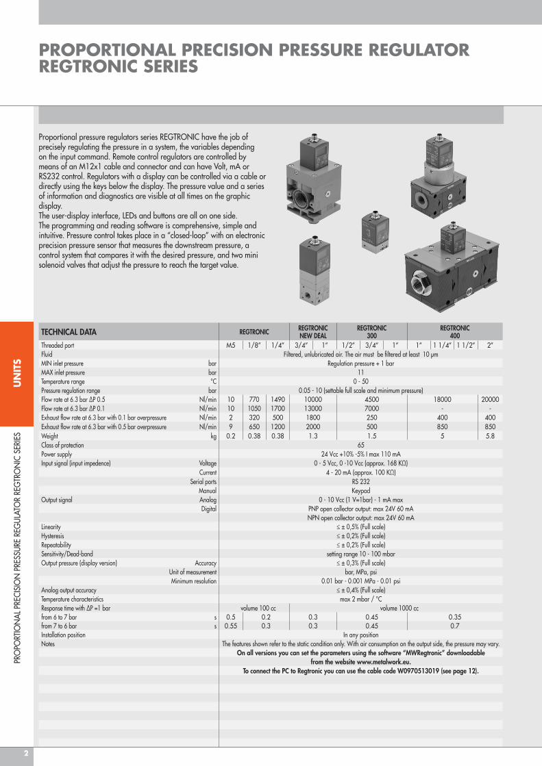
Proportional pressure regulators series REGTRONIC have the job of precisely regulating the pressure in a system, the variables depending on the input command. Remote control regulators are controlled by means of an M12x1 cable and connector and can have Volt, mA or RS232 control. Regulators with a display can be controlled via a cable or directly using the keys below the display. The pressure value and a series of information and diagnostics are visible at all times on the graphic display. The user-display interface, LEDs and buttons are all on one side.The programming and reading software is comprehensive, simple and intuitive. Pressure control takes place in a “closed-loop” with an electronic precision pressure sensor that measures the downstream pressure, a control system that compares it with the desired pressure, and two mini solenoid valves that adjust the pressure to reach the target value.
PRO
PORT
ION
AL P
RECI
SIO
N P
RESS
URE
REG
ULAT
OR
REG
TRO
NIC
SER
IES
PROPORTIONAL PRECISION PRESSURE REGULATOR REGTRONIC SERIES
TECHNICAL DATA REGTRONIC REGTRONICNEW DEAL
REGTRONIC300
REGTRONIC400
Threaded port M5 1/8’’ 1/4’’ 3/4’’ 1’’ 1/2’’ 3/4’’ 1’’ 1’’ 1 1/4’’ 1 1/2’’ 2’’Fluid Filtered, unlubricated air. The air must be filtered at least 10 µmMIN inlet pressure bar Regulation pressure + 1 barMAX inlet pressure bar 11Temperature range °C 0 - 50Pressure regulation range bar 0.05 - 10 (settable full scale and minimum pressure)Flow rate at 6.3 bar ∆P 0.5 Nl/min 10 770 1490 10000 4500 18000 20000Flow rate at 6.3 bar ∆P 0.1 Nl/min 10 1050 1700 13000 7000 - -Exhaust flow rate at 6.3 bar with 0.1 bar overpressure Nl/min 2 320 500 1800 250 400 400Exhaust flow rate at 6.3 bar with 0.5 bar overpressure Nl/min 9 650 1200 2000 500 850 850Weight kg 0.2 0.38 0.38 1.3 1.5 5 5.8Class of protection 65 Power supply 24 Vcc +10% -5% I max 110 mAInput signal (input impedence) Voltage 0 - 5 Vcc, 0 -10 Vcc (approx. 168 KΩ)
Current 4 - 20 mA (approx. 100 KΩ)Serial ports RS 232
Manual KeypadOutput signal Analog 0 - 10 Vcc (1 V=1bar) - 1 mA max
Digital PNP open collector output: max 24V 60 mANPN open collector output: max 24V 60 mA
Linearity ≤ ± 0,5% (Full scale)Hysteresis ≤ ± 0,2% (Full scale)Repeatability ≤ ± 0,2% (Full scale)Sensitivity/Dead-band setting range 10 - 100 mbarOutput pressure (display version) Accuracy ≤ ± 0,3% (Full scale)
Unit of measurement bar, MPa, psiMinimum resolution 0.01 bar - 0.001 MPa - 0.01 psi
Analog output accuracy ≤ ± 0,4% (Full scale)Temperature characteristics max 2 mbar / °CResponse time with ∆P =1 bar volume 100 cc volume 1000 ccfrom 6 to 7 bar s 0.5 0.2 0.3 0.45 0.35from 7 to 6 bar s 0.55 0.3 0.3 0.45 0.7Installation position In any positionNotes The features shown refer to the static condition only. With air consumption on the output side, the pressure may vary.
On all versions you can set the parameters using the software “MWRegtronic” downloadablefrom the website www.metalwork.eu.
To connect the PC to Regtronic you can use the cable code W0970513019 (see page 12).
3
UN
ITS
PRO
PORT
ION
AL P
RECI
SIO
N P
RESS
URE
REG
ULAT
OR
REG
TRO
NIC
SER
IES
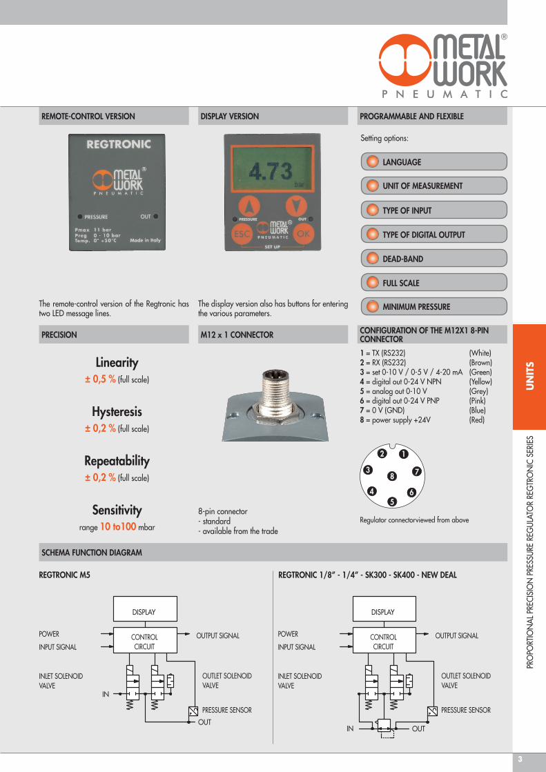
The remote-control version of the Regtronic has two LED message lines.
The display version also has buttons for entering the various parameters.
Setting options:
REGTRONIC M5 REGTRONIC 1/8” - 1/4” - SK300 - SK400 - NEW DEAL
LANGUAGE
UNIT OF MEASUREMENT
TYPE OF INPUT
TYPE OF DIGITAL OUTPUT
DEAD-BAND
FULL SCALE
MINIMUM PRESSURE
8-pin connector- standard- available from the trade
Linearity± 0,5 % (full scale)
Hysteresis± 0,2 % (full scale)
Repeatability± 0,2 % (full scale)
Sensitivityrange 10 to100 mbar
SCHEMA FUNCTION DIAGRAM
1 = TX (RS232) (White)2 = RX (RS232) (Brown)3 = set 0-10 V / 0-5 V / 4-20 mA (Green)4 = digital out 0-24 V NPN (Yellow) 5 = analog out 0-10 V (Grey)6 = digital out 0-24 V PNP (Pink) 7 = 0 V (GND) (Blue)8 = power supply +24V (Red)
Regulator connectorviewed from above
P
DISPLAY
CONTROLCIRCUIT
OUTPUT SIGNAL
OUTLET SOLENOIDVALVE
PRESSURE SENSOR
POWER
INPUT SIGNAL
INLET SOLENOIDVALVE
IN
OUTP
DISPLAY
CONTROLCIRCUIT
OUTPUT SIGNAL
OUTLET SOLENOIDVALVE
PRESSURE SENSOR
POWER
INPUT SIGNAL
INLET SOLENOIDVALVE
IN OUT
1
7
65
8
4
3
2
REMOTE-CONTROL VERSION
PRECISION
DISPLAY VERSION
M12 x 1 CONNECTOR
PROGRAMMABLE AND FLEXIBLE
CONFIGURATION OF THE M12X1 8-PIN CONNECTOR
4
UN
ITS
REG
TRO
NIC
M5
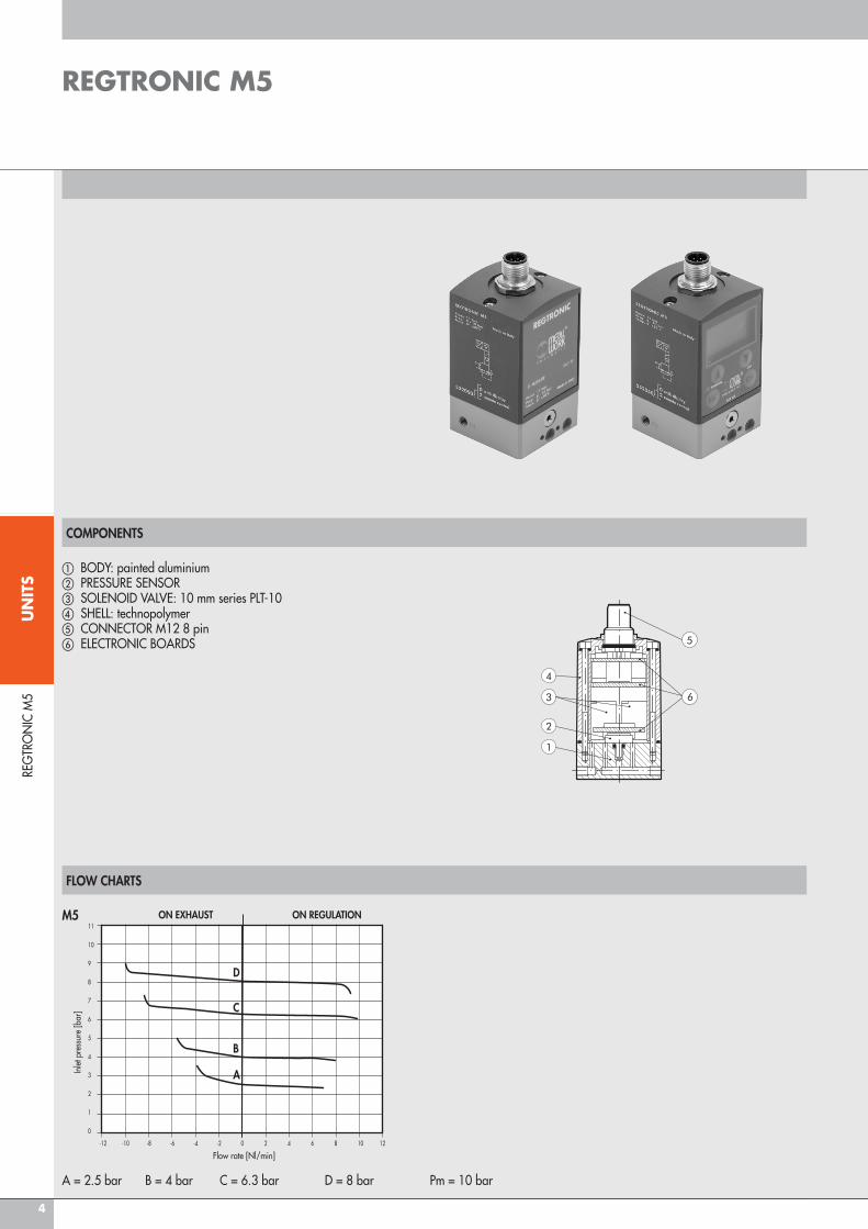
FLOW CHARTS
REGTRONIC M5
COMPONENTS
a BODY: painted aluminiumb PRESSURE SENSORc SOLENOID VALVE: 10 mm series PLT-10d SHELL: technopolymere CONNECTOR M12 8 pinf ELECTRONIC BOARDS
A = 2.5 bar B = 4 bar C = 6.3 bar D = 8 bar Pm = 10 bar
ON EXHAUST ON REGULATION
D
C
B
AInle
t pre
ssur
e [b
ar]
Flow rate [Nl/min]-12 -10 -8 -6 -4 -2 0 2 4 6 8 10 12
11
10
9
8
7
6
5
4
3
2
1
0
M5
5
UN
ITS
REG
TRO
NIC
M5
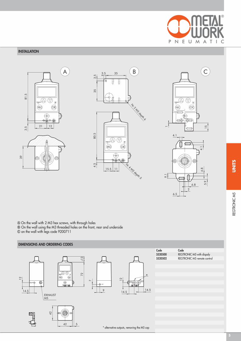
INSTALLATION
DIMENSIONS AND ORDERING CODES
Code Code5520500 REGTRONIC M5 with dispaly5520502 REGTRONIC M5 remote control
A On the wall with 2 M3 hex screws, with through holes B On the wall using the M3 threaded holes on the front, rear and underside C on the wall with legs code 9200711
* alternative outputs, removing the M5 cap
6
UN
ITS
REG
TRO
NIC
1/8
’’; 1
/4’’
FLOW CHARTS
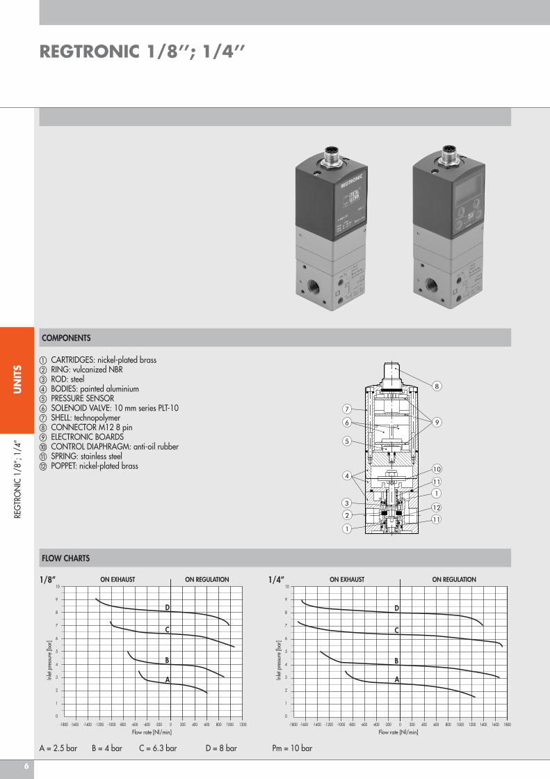
REGTRONIC 1/8’’; 1/4’’
COMPONENTS
a CARTRIDGES: nickel-plated brassb RING: vulcanized NBRc ROD: steeld BODIES: painted aluminiume PRESSURE SENSORf SOLENOID VALVE: 10 mm series PLT-10g SHELL: technopolymerh CONNECTOR M12 8 pini ELECTRONIC BOARDSj CONTROL DIAPHRAGM: anti-oil rubber k SPRING: stainless steell POPPET: nickel-plated brass
A = 2.5 bar B = 4 bar C = 6.3 bar D = 8 bar Pm = 10 bar
ON EXHAUST ON REGULATION
D
C
B
AInle
t pre
ssur
e [b
ar]
Flow rate [Nl/min]-1800 -1600 -1400 -1200 -1000 -800 -600 -400 -200 0 200 400 600 800 1000 1200
10
9
8
7
6
5
4
3
2
1
0
1/8’’ ON EXHAUST ON REGULATION
D
C
B
AInle
t pre
ssur
e [b
ar]
Flow rate [Nl/min]-1800 -1600 -1400 -1200 -1000 -800 -600 -400 -200 0 200 400 600 800 1000 1200 1400 1600 1800
10
9
8
7
6
5
4
3
2
1
0
1/4’’
7
UN
ITS
REG
TRO
NIC
1/8
’’; 1
/4’’
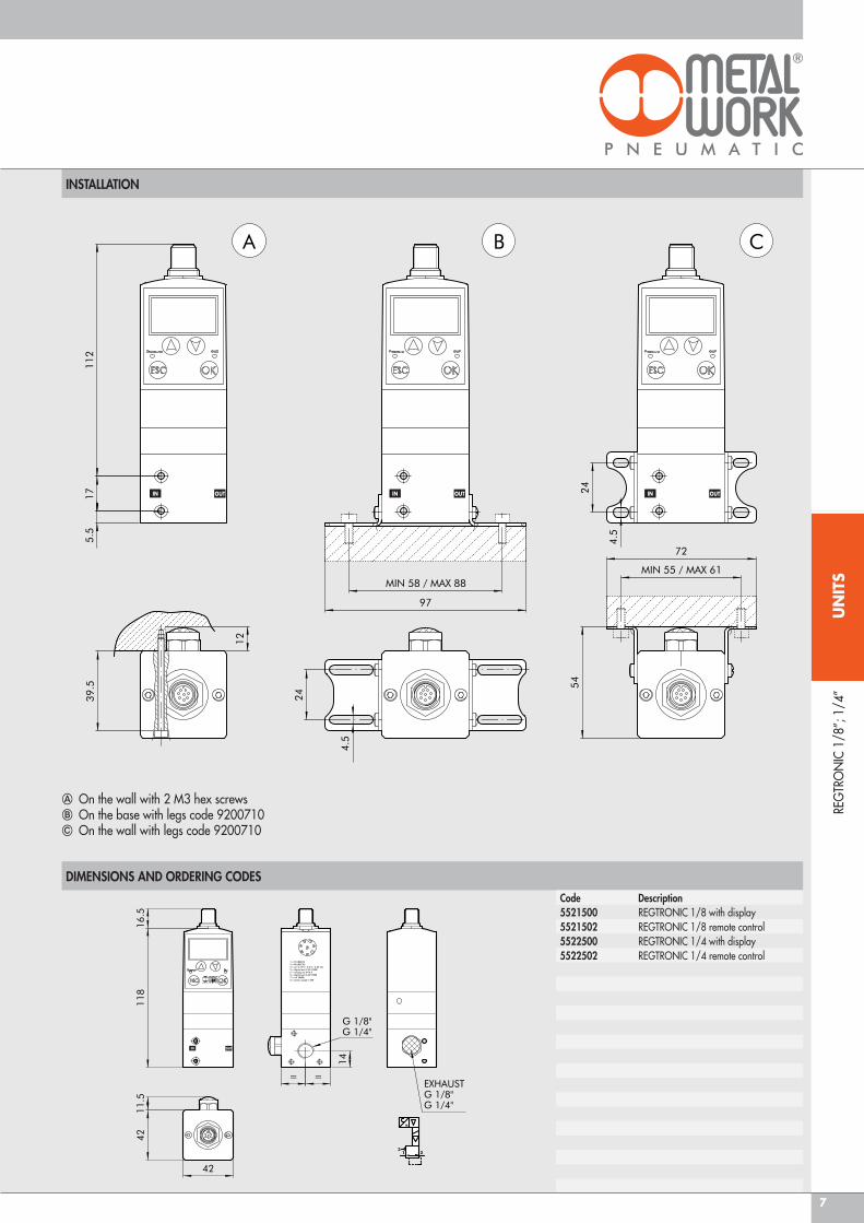
INSTALLATION
A On the wall with 2 M3 hex screws B On the base with legs code 9200710C On the wall with legs code 9200710
Code Description 5521500 REGTRONIC 1/8 with display5521502 REGTRONIC 1/8 remote control5522500 REGTRONIC 1/4 with display5522502 REGTRONIC 1/4 remote control
DIMENSIONS AND ORDERING CODES
IN OUT IN OUT IN OUT
IN OUT

8
UN
ITS
FLOW CHARTS
a REGULATOR BODY: aluminiumb LOWER CAP: aluminiumc UPPER PLATE: aluminiumd SPACER: aluminiume GASKET: NBRf PISTON ROD: aluminiumg CAP FOR PLAIN GASKET: OT58 brassh PLAIN GASKET: NBRi ROD: OT58 brassj VALVE: OT58 brassk VALVE SPRING: steell GASKETS: NBRm ELECTRONIC BOARDSn CONNECTOR M12 8 PINo PRESSURE SENSORp SOLENOID VALVE: 10 mm series PLT-10q SHELL: tecnopolymer
DIMENSIONS AND ORDERING CODES
Code Description1520003 REGTRONIC 3/4 with display1520004 REGTRONIC 3/4 remote control1620003 REGTRONIC 1 with display1620004 REGTRONIC 1 remote control
A = 2.5 bar B = 4 bar C = 6.3 bar Pm = 10 bar
ON EXHAUST ON REGULATION
Inle
t pre
ssur
e [b
ar]
Flow rate [Nl/min]-3000 -1500 0 1500 3000 4500 6000 7500 9000 10500 12000 13500
8
7
6
5
4
3
2
1
0
C
B
A
REG
TRO
NIC
NEW
DEA
L
REGTRONIC
COMPONENTS
9
UN
ITS
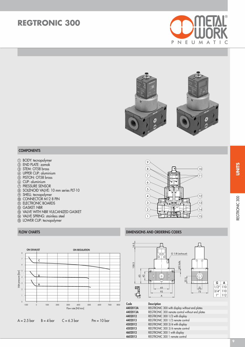
COMPONENTS
a BODY: tecnopolymerb END PLATE: zamakc STEM: OT58 brassd UPPER CUP: aluminiume PISTON: OT58 brassf CUP: aluminiumg PRESSURE SENSORh SOLENOID VALVE: 10 mm series PLT-10i SHELL: tecnopolymerj CONNECTOR M12 8 PINk ELECTRONIC BOARDSl GASKET: NBRm VALVE WITH NBR VULCANIZED GASKETn VALVE SPRING: stainless steelo LOWER CUP: tecnopolymer RE
GTR
ON
IC 3
00
REGTRONIC 300
FLOW CHARTS DIMENSIONS AND ORDERING CODES
Code Description 4402012A REGTRONIC 300 with display without end plates4402013A REGTRONIC 300 remote control without end plates4402012 REGTRONIC 300 1/2 with display4402013 REGTRONIC 300 1/2 remote control4502012 REGTRONIC 300 3/4 with display4502013 REGTRONIC 300 3/4 remote control4602012 REGTRONIC 300 1 with display4602013 REGTRONIC 300 1 remote control
G A 1/2’’ 110 3/4’’ 110 1’’ 112
Inle
t pre
ssur
e [b
ar]
8
7
6
5
4
3
2
1
0
A = 2.5 bar B = 4 bar C = 6.3 bar Pm = 10 bar
ON EXHAUST
Flow rate [Nl/min]-1000 0 1000 2000 3000 4000 5000 6000 7000 8000
C
B
A
ON REGULATION
10
UN
ITS
FLOW CHARTS
COMPONENTS
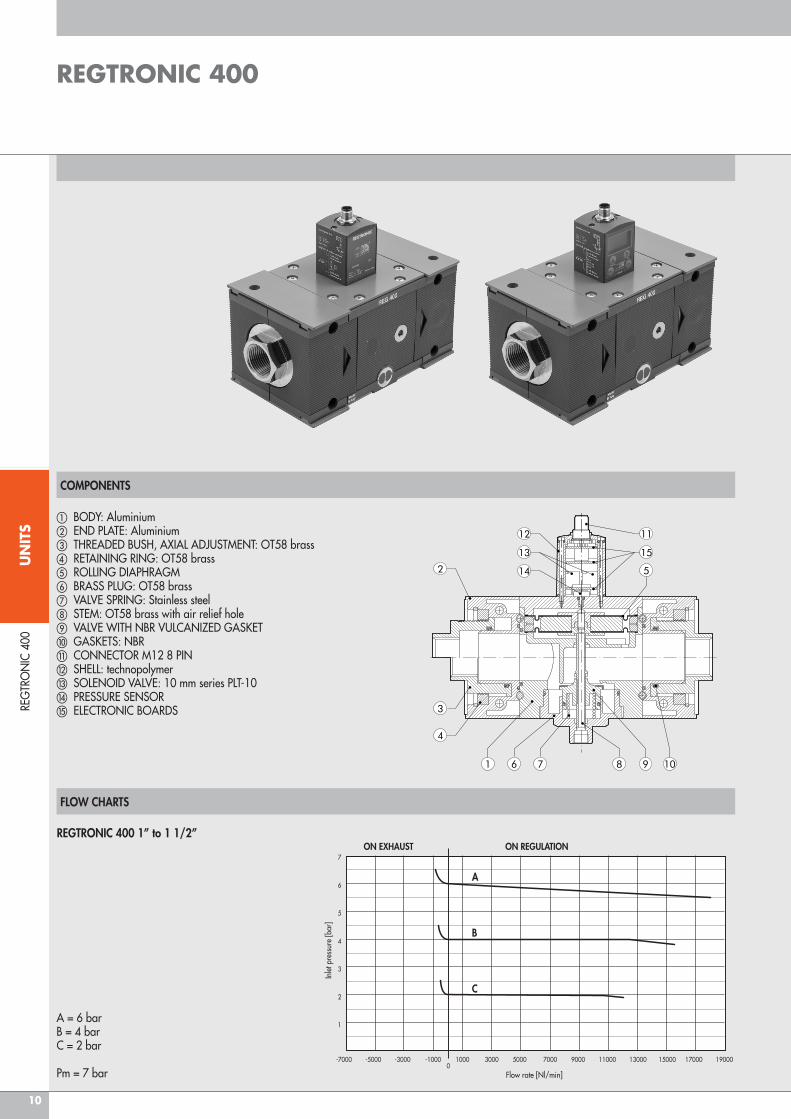
a BODY: Aluminiumb END PLATE: Aluminiumc THREADED BUSH, AXIAL ADJUSTMENT: OT58 brassd RETAINING RING: OT58 brasse ROLLING DIAPHRAGMf BRASS PLUG: OT58 brassg VALVE SPRING: Stainless steelh STEM: OT58 brass with air relief holei VALVE WITH NBR VULCANIZED GASKETj GASKETS: NBRk CONNECTOR M12 8 PINl SHELL: technopolymerm SOLENOID VALVE: 10 mm series PLT-10n PRESSURE SENSORo ELECTRONIC BOARDS
REGTRONIC 400 1’’ to 1 1/2’’
A = 6 barB = 4 barC = 2 bar
Pm = 7 bar
ON EXHAUST ON REGULATION
A
B
C
Inle
t pre
ssur
e [b
ar]
Flow rate [Nl/min]
-7000 -5000 -3000 -1000 1000 3000 5000 7000 9000 11000 13000 15000 17000 190000
7
6
5
4
3
2
1
REG
TRO
NIC
400
REGTRONIC 400
11
UN
ITS
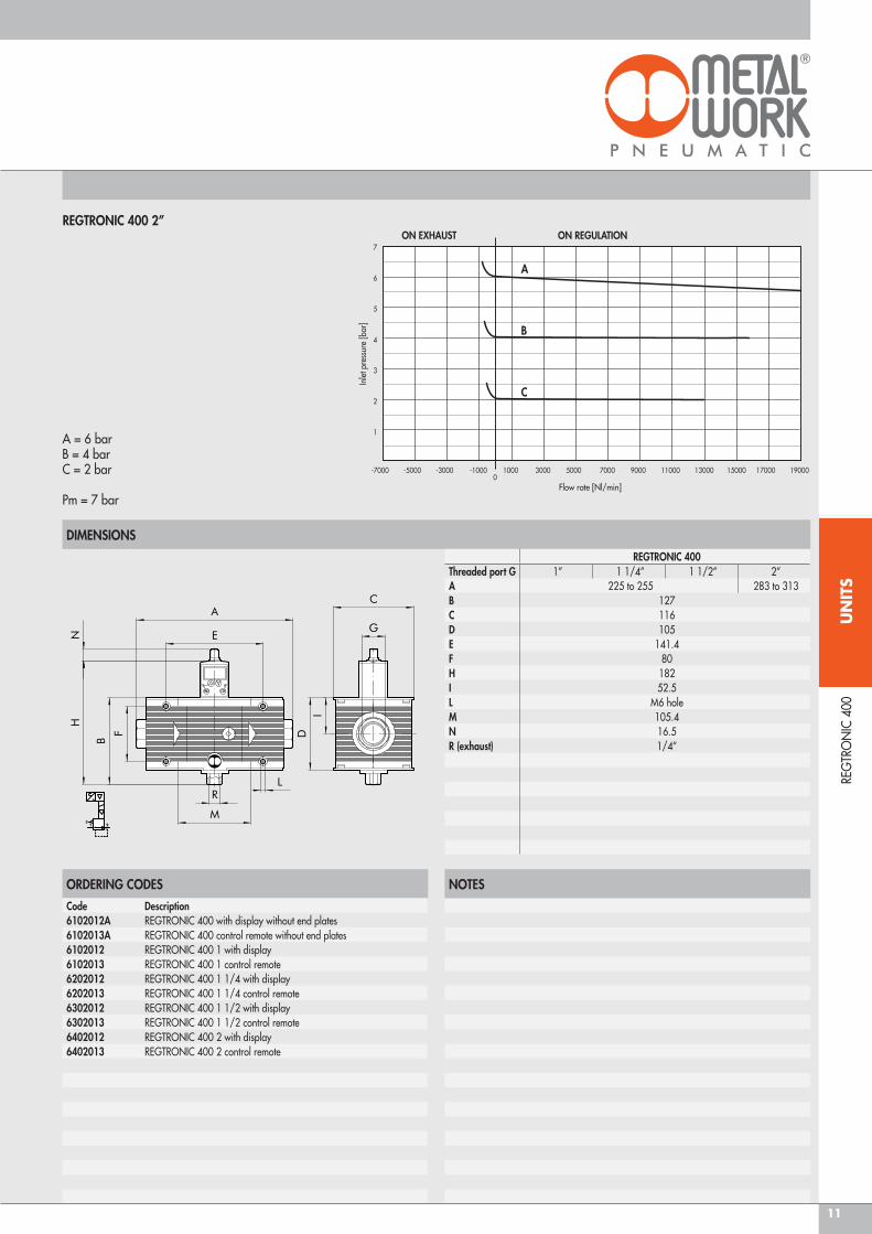
DIMENSIONS
ORDERING CODES NOTES
Code Description6102012A REGTRONIC 400 with display without end plates6102013A REGTRONIC 400 control remote without end plates6102012 REGTRONIC 400 1 with display6102013 REGTRONIC 400 1 control remote6202012 REGTRONIC 400 1 1/4 with display6202013 REGTRONIC 400 1 1/4 control remote6302012 REGTRONIC 400 1 1/2 with display6302013 REGTRONIC 400 1 1/2 control remote6402012 REGTRONIC 400 2 with display6402013 REGTRONIC 400 2 control remote
REGTRONIC 400 2’’
A = 6 barB = 4 barC = 2 bar
Pm = 7 bar
ON EXHAUST ON REGULATION
A
B
C
Inle
t pre
ssur
e [b
ar]
Flow rate [Nl/min]
-7000 -5000 -3000 -1000 1000 3000 5000 7000 9000 11000 13000 15000 17000 190000
7
6
5
4
3
2
1
REGTRONIC 400Threaded port G 1” 1 1/4’’ 1 1/2’’ 2’’A 225 to 255 283 to 313B 127C 116D 105E 141.4F 80H 182I 52.5L M6 holeM 105.4N 16.5R (exhaust) 1/4’’
REG
TRO
NIC
400
12
UN
ITS
ACC
ESSO
RIES
REG
TRO
NIC
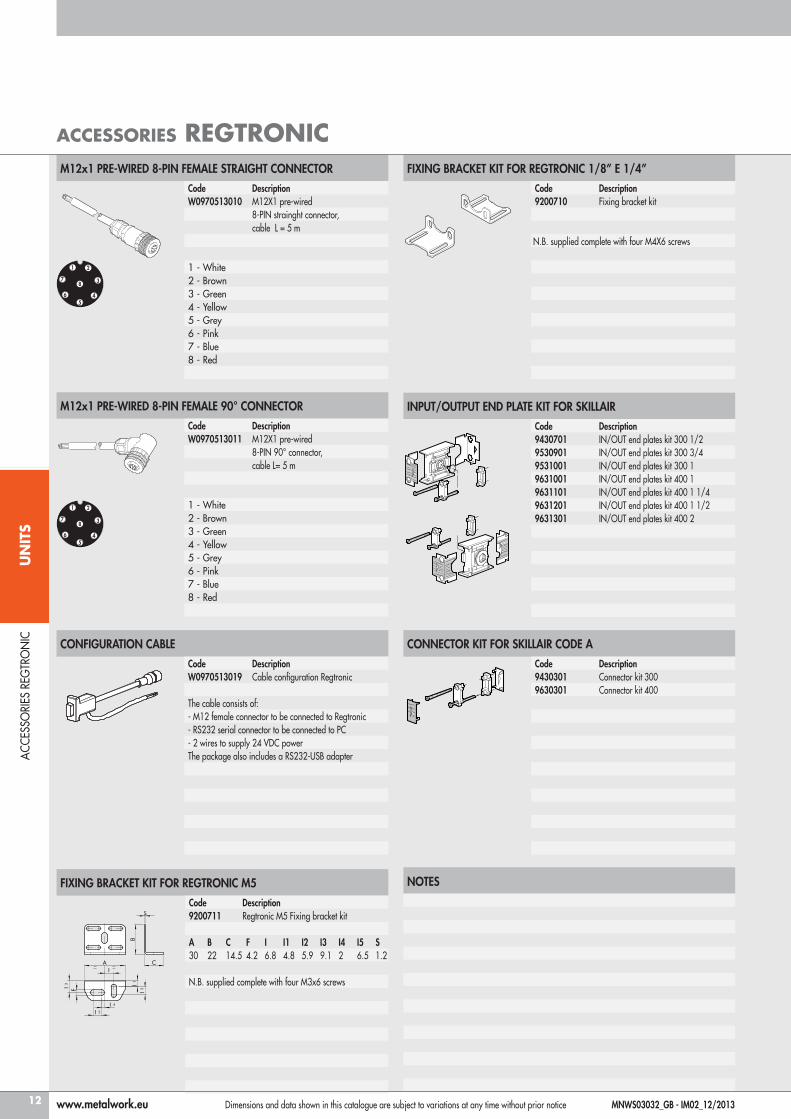
ACCESSORIES REGTRONIC
INPUT/OUTPUT END PLATE KIT FOR SKILLAIR
Code Description9430701 IN/OUT end plates kit 300 1/29530901 IN/OUT end plates kit 300 3/49531001 IN/OUT end plates kit 300 19631001 IN/OUT end plates kit 400 19631101 IN/OUT end plates kit 400 1 1/49631201 IN/OUT end plates kit 400 1 1/29631301 IN/OUT end plates kit 400 2
M12x1 PRE-WIRED 8-PIN FEMALE 90° CONNECTOR
Code DescriptionW0970513011 M12X1 pre-wired
8-PIN 90° connector,cable L= 5 m
1 - White2 - Brown3 - Green4 - Yellow5 - Grey6 - Pink7 - Blue8 - Red
CONNECTOR KIT FOR SKILLAIR CODE A
Code Description9430301 Connector kit 3009630301 Connector kit 400
CONFIGURATION CABLE
Code DescriptionW0970513019 Cable configuration Regtronic
The cable consists of:- M12 female connector to be connected to Regtronic- RS232 serial connector to be connected to PC- 2 wires to supply 24 VDC powerThe package also includes a RS232-USB adapter
FIXING BRACKET KIT FOR REGTRONIC 1/8’’ E 1/4’’
Code Description9200710 Fixing bracket kit
N.B. supplied complete with four M4X6 screws
FIXING BRACKET KIT FOR REGTRONIC M5
Code Description9200711 Regtronic M5 Fixing bracket kit
A B C F I I1 I2 I3 I4 I5 S30 22 14.5 4.2 6.8 4.8 5.9 9.1 2 6.5 1.2
N.B. supplied complete with four M3x6 screws
M12x1 PRE-WIRED 8-PIN FEMALE STRAIGHT CONNECTOR
Code DescriptionW0970513010 M12X1 pre-wired
8-PIN strainght connector,cable L = 5 m
1 - White2 - Brown3 - Green4 - Yellow5 - Grey6 - Pink7 - Blue8 - Red
2
3
45
8
6
7
1
2
3
45
8
6
7
1
NOTES
www.metalwork.eu Dimensions and data shown in this catalogue are subject to variations at any time without prior notice MNWS03032_GB - IM02_12/2013