Embed Size (px)
Citation preview
1
EXECUTIVE SUMMARY
1. INTRODUCTION Solid waste management has become a major environmental issue in India. The increase in
population and urbanization are largely responsible for the increase in solid waste.Municipal Solid Waste (MSW) includes mostly residential waste, commercial waste, andmarket waste, slaughter house waste, street sweeping etc. It consists of biodegradable waste,recyclable waste, inert waste, combustible and non-combustible waste etc.
As per information received from State Pollution Control Boards/ Pollution Control Committees, (inbetween the year 2009- 2012), 1, 27,486 TPD municipal solid waste is generated in thecountry during 2011-12. Out of which, 89,334 TPD (70%) of MSW is collected and 15,881 TPD(12.45%) is processed or treated, which are not only impossible to reclaim because ofhaphazard manner of dumping, but also have serious environmental implications in terms ofground water pollution and Global Warming.
Project Highlights:
Project Details Proposed Municipal Solid Waste Management.Site Khasra No- 2031, Village- Keerkheda (Sanganer), Tehsil &
District- bhilwara (Raj)Land Area Required 2.9 hectare
Water Source From State/ City Jal BoardWater RequirementElectrical Power Source State/ City Electricity Board
Electrical Power DemandFuelsEmployment OpportunityCapital Investment (INR) 10.06 croresAdditional EnvironmentalMitigation Cost (INR)
2. PROJECT DETAILS
NEED FOR THE PROJECTAt present the MSW disposal is carried out in an unscientific manner by open disposal ofmixed waste. The Government of Rajasthan thus proposes to strengthen the MSWM systemcovering collection, segregation, recycling, transportation processing and disposal in ULBsso as to comply with the service level benchmarks of the GoI and also to meet its goal of
2
maintaining growth rates without jeopardizing the environment and its natural resources. Thesetting up of proposed project at Bhilwara, which is one of the ULBs, is aimed at fulfilling theabove objectives. The RMHS has proposed composting & RDF production with sanitarylandfill.Location of the projectThe proposed project is situated at Khasra No- 2031, Village- Keerkheda (Sanganer), Tehsil &District- Bhilwara (Raj). The project site area is 2.9 hectare, which lies about 10 km North-Westof Bhilwara town.
CONECTIVITYThe proposed site has well developed transport infrastructure, which has all basic amenities thatare feasible for industrial projects viability.
Table 4.1 Basic Amenities
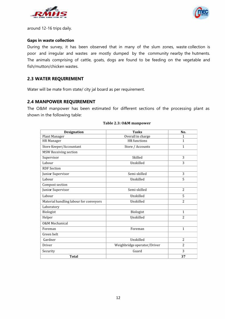
MANPOWER REQUIREMENTThe O&M manpower has been estimated for different sections of the processing plant is 37.
3. PROPOSED SOLID WASTE MANAGEMENT FACILITIES A proper and scientific integrated waste management system would upgrade
significantly the living status of the people residing there and also ensure eradication of someof the major health related problems when combined with 100% compliance to clean seweragefacilities and pure drinking water supply in all the Wards.
A two bin system shall be introduced for waste collection at all levels and sources ofgeneration. The 2-bin system would essentially comprise of (i) principally wet or moistwaste comprising of kitchen waste, food waste etc. which are bio-degradable and (ii) principallywaste papers, plastics, sanitary napkins, rags, cardboards, etc. many of which are recyclable.
Primary waste would be collected from all households, slum areas and market palace &community centre within each ward of the ULB.
Secondary collection includes picking up waste from community bins, waste storage depotsor transfer stations and transporting it to waste processing sites or disposal wastes.
It is estimated that about 40-45% of the total waste generation would be rejects or wastes inthe real term, which if no other use could be found out need to be land filled in a propermanner. The secured waste landfill area shall be designed for an initial period of 10-12 years of
S No Nearest NameDistance & Direction (Fromplot Boundary)
1. Railway Station Bhilwara Railway Station ~ 7.5 km in SW
2. Airport Dabok Airport Udaipur ~ 117 km in SW
3. Highway NH 758 ~4.0 km in South
3
storage to be later expanded to 25 years based on land area availability. Energy can be recovered from the organic fraction of waste (biodegradable as well as
non‐ biodegradable) deploying both Bio‐chemical and Thermo‐chemical conversionprocesses. Bio‐ chemical process is based on enzymatic decomposition of organic matter bymicrobial action to produce methane gas or alcohol.
Refuse derived fuels prepared from MSW can be sold in the market (cement plants installedclose to such projects are consistent buyers for such fuel) or directly used in boilers for steamgeneration.
The guidelines shall be taken care while handling, treating and disposing the waste so as toprevent contamination of ground water, surface water and ambient air quality. Thequality requirements of the RDF and compost are maintained as per the Solid WasteManagement Rules, 2016& acceptance of the market (FCO specification).
A ramp with suitable gradient will be provided along the length of the composting pits,which will be used as an unloading platform for incoming vehicles loaded with garbage.Compactors/trucks (as applicable) will enter through this ramp only and unload the garbageinside the pits. The height of ramp will be decided as per economic design.
As per the concept of drying, 28 no. of pits (of RCC) will be constructed for retention of 25days material. Waste will be unloaded inside this pit. Proper aeration will be provided bytumbling the waste after 3 to 4 days to maintain aerobic conditions.
MSW will be fed in the centre of this ballistic separator through a hopper/chute and willbe screened in two stages. The oversize material from 100 mm size screen will be taken to ashredder where it will be converted into fluff of 50‐80 mm size and to storage thereafter.Material of size between 60 to 100 mm will be directly taken into RDF storage.
The undersize material coming out from 10 mm screen will be fed to 4 mm trammel screen.Once this equipment screens material, it gradually feeds the same to the consecutiveequipment at a controlled rate.
Leachate contains a host of chemicals that may be toxic to both humans and environment.Also, the high Bio‐chemical Oxygen Demand (BOD) of leachate makes its treatmentinevitable. Based upon characteristics of the leachate collected, the treatment units will beprovided.
There will be a dedicated engineered sanitary landfill site which will handle the rejects fromthe MSW processing facility. Deposition of inert in conical heaps over the landfill site andspreading these heaps using a tracked bull dozer is a low cost and easy option.
4. SITE SELECTION AND SOCIAL ASPECTSLand Use: The detailed Land area break up is shown in Table 4.2
Table 4.2 Land Area Breakup
S. No. Particulars Area (sq m)1. Plant area
4
2. Roads/ Corridors3. Plantation4. Open area
TOTAL
Land Ownership:Land is located at Khasra No- 2031, Village- Keerkheda (Sanganer), Tehsil and District- Bhilwara(raj.)The proposed land an area of 2.9 hectare for municipal Solid waste management is a govt. land ofNagar Parishad, Bhilwara which has been granted to Rollz Material Handling System Pvt. Ltd onlease vide letter no. N.P.B./Works/2016-17/8965 dated 01.12.2016.
TOPOGRAPHYThe topography of the study area (10 km radius) is almost flat. In buffer area there is four reservedforest and a protected forest are present within 15 km.
SOIL CLASSIFICATIONGeologically Bhilwara Supergroup occupies major part of the district. The Vindhyan Supergrouprepresented by sandstone, shale and limestone is exposed in south-eastern part of the districtalong the great boundary fault. The Gogunda Group is exposed in extreme north-western part ofthe district and the Kumbhalgarh Group occupies small area in south-western part of the district,both belonging to Delhi Supergroup. The Aravalli Supergroup exposed in western part of thedistrict is represented by Dovda Group.
CLIMATE DATA FROM SECONDARY SOURCESThe project falls in dry climate area. During the summer season it is very hot, but far less than theother cities of Rajasthan. The summer season spans between the months of April and June. May isthe hottest month of the year when, the temperature raises up to 42° - 43° Celsius. During thisperiod the maximum temperature is approximately 43º Celsius and the minimum temperature isaround 28º Celsius. The winters are cool and pleasant spanning between November and February.The temperature during the winter season approximately varies within the range of 23° C(maximum) to 8° C (minimum). January is the coldest month of the season with temperaturedropping to nearly 8 degrees Celsius. The average annual rainfall is around 574 mm. The averagehumidity of is ~53 per cent. The topography of the study area is almost flat.
SOCIAL INFRASTRUCTURE AVAILABLESocial infrastructure like hospitals, educational facilities, temple, community centre, roads,telecommunication and others similar are available within 10 km radius.
5. ENVIRONMENTAL PROTECTION MEASURES
5
AIR POLLUTION CONTROL MEASURES Maintaining and/or re‐establishment of a grass cover on area where there is no
on‐going activity Frequent watering of unsealed roads and stockpile area‐ cover material Blacktop of the roads as and when they are settled and ready for the same Repair, relaying of blacktop roads from the landfill area to the main road Using dust control sprays during loading and unloading of wastes
WATER POLLUTION CONTROL MEASURESConstruction Phase: During the construction phase, a septic tank shall be provided totreat the domestic wastewater generated due to labor settlements. Temporary facility wouldhave impermeable flooring and proper leachate collection arrangement.Operation Phase: During initial composting i.e. for about 3 days, leachate will be released. Thisleachate shall be utilized to maintain required moisture level in composting pits. Howeverthe excess leachate discharged shall be collected and treated before draining.
SOLID WASTE DISPOSAL MANAGEMENT PLANThe processing and disposal plant has been designed on latest technology involving accelerated andcomplete composting using thermophilic enzymes. Density separation along with above technologyenables effective and efficient segregation of compost, RDF combustibles, recyclables andinert comprising of construction and demolition waste. The construction and demolition waste soseparated is further planned to be converted into construction material thereby moving towardszero disposal in the landfill.
NOISE CONTROL MEASURES Maintaining the site machinery in good operating condition Regular maintenance of systems and installation of noise control equipment wherever
required Development of green belt all around the site Periodical monitoring of noise levels
GREEN BELT DEVELOPMENTA green belt is provided to mitigate various emissions. Green belts are wide strip of trees andshrubs planted in rows to reduce air velocity there by facilitating settling of the particles on theleaf surfaces and allowing absorption of the pollutant gases.HEATH AND SAFETY MANAGEMENT:The health and safety of all those who work at the Plant shall be ensured.All necessary tools and equipment, including personal protective equipment, shall be properlymaintained. Defective tools and equipment shall be repaired or replaced immediately.
6. Rehabilitation and Resettlement (R&R) Plan
6
The proposed project is new project at already converted land for municipal solid wastedumping site of Nagar Parishad Bhilwara. The proposed land an area of 2.9 hectare formunicipal Solid waste management is a govt. land of Nagar parishad, Bhilwara which has beenLand is located at Khasra No- 2031, Village- Keerkheda (Sanganer), Tehsil and District- Bhilwara(raj.)The proposed land an area of 2.9 hectare for municipal Solid waste management is a govt. land ofNagar parishad, Bhilwara which has been granted to Rollz Material Handling System Pvt. Ltd onlease vide letter no. N.P.B./Works/2016-17/8965 dated 01.12.2016.Thus rehabilitation and resettlement plan in not applicable in this particular project.
7. PROJECT SCHEDULE & COST ESTIMATES
The whole project is estimated to be completed in about 9 months following approval of DPR and6 months from obtaining environmental clearance whichever is later. It is envisaged that theproposed facility would be operational from January 2018.
Project CostThe estimated project cost is Rs 10.06 Crores for the year 2016- 2017, although this will beoperational from 2018. The capital investment of Land & site development, Civil works, Plant &Machinery and Particulars of interface equipment.
7
CHAPTER 1 – INTRODUCTION
Solid waste management has become a major environmental issue in India. The increase inpopulation and urbanization are largely responsible for the increase in solid waste.Municipal Solid Waste (MSW) includes mostly residential waste, commercial waste, and marketwaste, slaughter house waste, street sweeping etc. It consists of biodegradable waste, recyclablewaste, inert waste, combustible and non-combustible waste etc.As per information received from State Pollution Control Boards/ Pollution Control Committees, (inbetween the year 2009- 2012), 1, 27,486 TPD municipal solid waste is generated in the countryduring 2011-12. Out of which, 89,334 TPD (70%) of MSW is collected and 15,881 TPD (12.45%) isprocessed or treated, which are not only impossible to reclaim because of haphazard manner ofdumping, but also have serious environmental implications in terms of ground water pollution andGlobal Warming.The Ministry of Environment & Forest (MoEF), Government of India had formulated MSWrule 2000 and updated in 2016 as SWM Rules 2016. These rules are formulated forcollection, storage, transportation, sorting and segregation, processing and disposal ofmunicipal solid wastes as per the rules. Reduces waste sent to the landfill, which may have negative impacts on groundwater and
air quality; Reduce emissions from energy consumption, as waste when recycled requires less
energy than making goods from virgin materials thereby reducing the energy demand andpressure on non renewable sources; contributes to climate change by reducing methaneemissions from landfills.
Waste prevention and recycling (including composting) divert organic wastes from landfills,reducing the methane released when these materials decompose.
Reduction in quantum of waste by diverting it to recycling and other processing unitreduces the landfill costs;
An effective waste management implies the concept of 3Rs e.g. reduce, reuse and recyclewaste matter leading to introduction of more and more of waste matter into the value chainleading to economic benefits;
Waste management being a labour intensive activity, it helps in employment generation. The Implementation of Municipal solid Waste (MSW) Management is an important component
of the Government of India's (GoI) "Swachh Bharat Mission" (SBM) - component IV.
1.1 IDENTIFICATION OF THE PROJECTM/s Rollz Material Handling Systems Pvt. Ltd (RMHS) participated in the competitive biddingprocess carried out by Rajasthan Government and succeeded in winning the bid for Bhilwara. Theconcession period (the “Concession Period”) for this project is for a term of 30 years includingconstruction and implementation of the project. The RMHS has proposed composting & RDFproduction with sanitary landfill at Land is located at Khasra No- 2031, Village- Keerkheda(Sanganer), Tehsil and District- Bhilwara (raj.)
8
1.2 PROJECT OBJECTIVESThe current Solid Waste Management (SWM) system is being carried out in most of the ULBsand including Bhilwara is collection of waste from door to door, market and community bins,transportation and disposal at the dump yard. No processing or treatment is undertaken. This hasled to environmental degradation, air pollution, surface and ground water contamination and posesgrave health hazards.The objective of the project is to implement solid waste management practices into action in theidentified ULBs and offer to the citizens of the state a clean, healthy and safe environment. TheSWM system would be in line with Integrated Municipal Solid Waste Management (ISWM)practices and adhering to the local regulations and professional best practices.
1.3 SCOPE OF THE REPORTGlobal Management and Engineering Consultants (GMEC) International have been appointed byRMHS for providing technical consultancy and assisting in obtaining environmental clearance forproposed integrated solid waste management facility for Bhilwara Municipality.Present report is prepared for submission of Form-I, application to SEIAA for obtainingEnvironmental Clearance as per the guidelines of EIA Notification, 2006 of MoEF & CC, GoI.
9
CHAPTER 2- PROJECT DETAILS
2.1 NEED FOR THE PROJECTAt present the MSW disposal is carried out in an unscientific manner by open disposal of mixedwaste. The Government of Rajasthan thus proposes to strengthen the MSWM system coveringcollection, segregation, recycling, transportation processing and disposal in ULBs so as to complywith the service level benchmarks of the GoI and also to meet its goal of maintaining growth rateswithout jeopardizing the environment and its natural resources. The setting up of proposed projectat bhilwara, which is one of the ULBs, is aimed at fulfilling the above objectives. The RMHS hasproposed composting & RDF production with sanitary landfill.
2.2 PROJECT DESCRIPTIONThe RMHS has proposed Composting & RDF production with Sanitary Landfill.
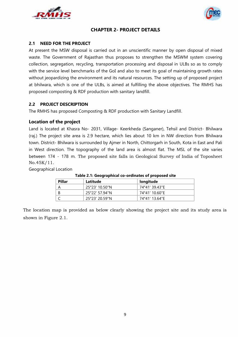
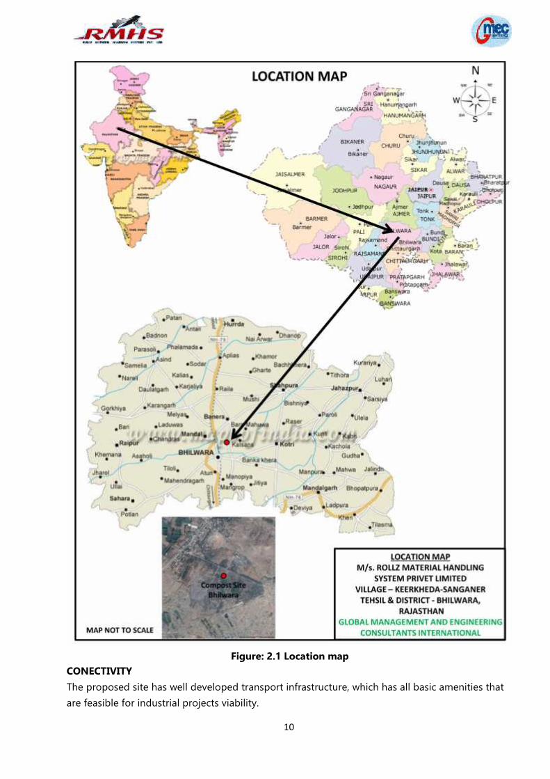
Location of the projectLand is located at Khasra No- 2031, Village- Keerkheda (Sanganer), Tehsil and District- Bhilwara(raj.) The project site area is 2.9 hectare, which lies about 10 km in NW direction from Bhilwaratown. District- Bhilwara is surrounded by Ajmer in North, Chittorgarh in South, Kota in East and Paliin West direction. The topography of the land area is almost flat. The MSL of the site variesbetween 174 - 178 m. The proposed site falls in Geological Survey of India of ToposheetNo.45K/11.Geographical Location
Table 2.1: Geographical co-ordinates of proposed sitePillar Latitude longitudeA 25°23' 10.50"N 74°41' 39.43"EB 25°22' 57.94"N 74°41' 10.60"EC 25°23' 20.59"N 74°41' 13.64"E
The location map is provided as below clearly showing the project site and its study area is
shown in Figure 2.1.
10
Figure: 2.1 Location mapCONECTIVITYThe proposed site has well developed transport infrastructure, which has all basic amenities thatare feasible for industrial projects viability.
11
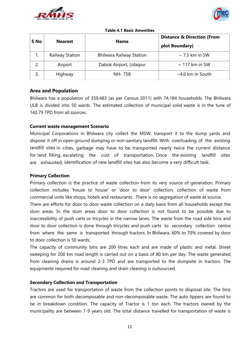
Table 4.1 Basic Amenities
Area and PopulationBhilwara has a population of 359,483 (as per Census 2011) with 74,184 households. The BhilwaraULB is divided into 50 wards. The estimated collection of municipal solid waste is in the tune of143.79 TPD from all sources.
Current waste management ScenarioMunicipal Corporations in Bhilwara city collect the MSW, transport it to the dump yards anddispose it off in open ground dumping or non‐sanitary landfill. With overloading of the existinglandfill sites in cities, garbage may have to be transported nearly twice the current distancefor land filling, escalating the cost of transportation. Once the existing landfill sitesare exhausted, identification of new landfill sites has also become a very difficult task.
Primary CollectionPrimary collection is the practice of waste collection from its very source of generation. Primarycollection includes ‘house to house’ or ‘door to door’ collection, collection of waste fromcommercial units like shops, hotels and restaurants. There is no segregation of waste at source.There are efforts for door to door waste collection on a daily basis from all households except theslum areas. In the slum areas door to door collection is not found to be possible due toinaccessibility of push carts or tricycles in the narrow lanes. The waste from the road side bins anddoor to door collection is done through tricycles and push carts to secondary collection centrefrom where the same is transported through tractors. In Bhilwara, 60% to 70% covered by doorto door collection is 50 wards.The capacity of community bins are 200 litres each and are made of plastic and metal. Streetsweeping for 200 km road length is carried out on a basis of 80 km per day. The waste generatedfrom cleaning drains is around 2-3 TPD and are transported to the dumpsite in tractors. Theequipments required for road cleaning and drain cleaning is outsourced.
Secondary Collection and TransportationTractors are used for transportation of waste from the collection points to disposal site. The binsare common for both decomposable and non-decomposable waste. The auto tippers are found tobe in breakdown condition. The capacity of Tractor is 1 ton each. The tractors owned by themunicipality are between 7-9 years old. The total distance travelled for transportation of waste is
S No Nearest NameDistance & Direction (Fromplot Boundary)
1. Railway Station Bhilwara Railway Station ~ 7.5 km in SW
2. Airport Dabok Airport, Udaipur ~ 117 km in SW
3. Highway NH- 758 ~4.0 km in South
12
uu
a nAkkkkk
around 12-16 trips daily.
Gaps in waste collectionDuring the survey, it has been observed that in many of the slum zones, waste collection ispoor and irregular and wastes are mostly dumped by the community nearby the hutments.The animals comprising of cattle, goats, dogs are found to be feeding on the vegetable andfish/mutton/chicken wastes.
2.3 WATER REQUIREMENT
Water will be mate from state/ city jal board as per requirement.
2.4 MANPOWER REQUIREMENTThe O&M manpower has been estimated for different sections of the processing plant asshown in the following table:
Table 2.3: O&M manpower
Designation Tasks No.Plant Manager Overall in charge 1HR Manager HR functions 1Store Keeper/Accountant Store / Accounts 1MSW Receiving sectionSupervisor Skilled 3Labour Unskilled 3RDF SectionJunior Supervisor Semi‐skilled 3Labour Unskilled 5Compost sectionJunior Supervisor Semi‐skilled 2Labour Unskilled 5Material handling labour for conveyors Unskilled 2LaboratoryBiologist Biologist 1Helper Unskilled 2O&M MechanicalForeman Foreman 1Green beltGardner Unskilled 2Driver Weighbridge operator/Driver 2Security Guard 3Total 37
13
CHAPTER 3- PROPOSED SOLID WASTE MANAGEMENT FACILITIES
3.1 TECHNICAL PROFILEVarious activities of the proposed integrated municipal solid waste management in Bhilwara ULBright from segregated primary collection, secondary collection and transport to the centralizedfacility at the respective municipalities, processing technology for waste composting, land filling ofthe rejects generated during secondary segregation and processing have been described in thesections below.
3.1.1 Integrated Waste ManagementA proper and scientific integrated waste management system would upgrade significantly theliving status of the people residing there and also ensure eradication of some of the major healthrelated problems when combined with 100% compliance to clean sewerage facilities and puredrinking water supply in all the Wards.
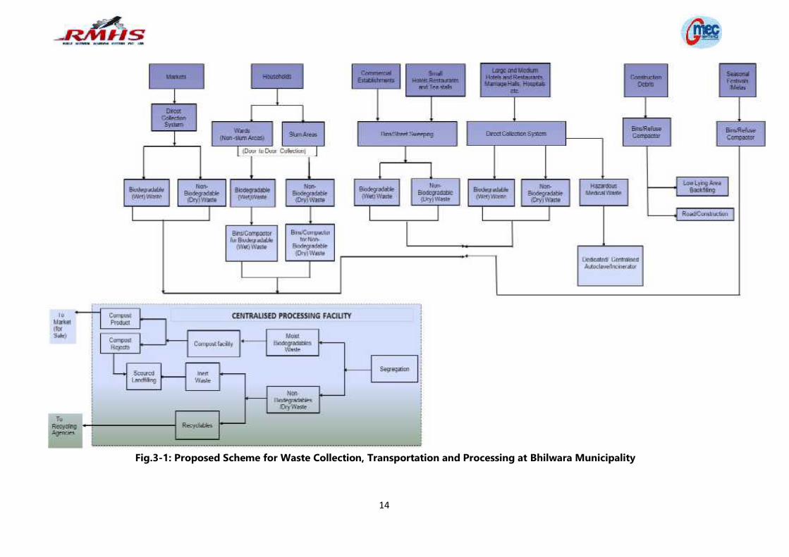
3.1.2 Proposed Scheme for Bhilwara Municipality for Solid Waste ManagementThe essential steps of an efficient solid waste management system are balanced on scientific andtimely collection both at primary and secondary levels, of waste generated from each householdacross all sections of people including the slum areas in each Ward of the municipality, regularstreet and drain sweepings, ensuring maximum segregation at origin followed up by secondarysegregation at waste processing facility and secured land filling of inert and non recyclablewaste fraction. Other important aspect of a sustainable waste processing facility is installingproper monitoring mechanism from the angle of environmental aspects, economic returns andcommunity acceptance. The proposed scheme for waste collection, transportation and processingfor Bhilwara Municipality is given in Fig. 3-1 on the next page.
14
Fig.3-1: Proposed Scheme for Waste Collection, Transportation and Processing at Bhilwara Municipality
15
3.2 WASTE COLLECTIONA two bin system shall be introduced for waste collection at all levels and sources of generation.The 2-bin system would essentially comprise of (i) principally wet or moist waste comprisingof kitchen waste, food waste etc. which are bio-degradable and (ii) principally waste papers,plastics, sanitary napkins, rags, cardboards, etc. many of which are recyclable. The street sweepingsand drain cleaning material and sludge would not be disposed along with the household municipalwaste collected. The silt collected from the drains would be disposed of in low lying lands. Thestreet litter collected which would be mixed in nature shall be brought to the processing facility forwaste processing and segregation.
3.2.1 Primary Waste CollectionPrimary waste would be collected from all households and slum areas within each ward of the ULB.For one first time Municipal Authorities in Bhilwara has to provide two (2) separate bins of color‘Blue’ and ‘Green’ to each household. The Blue color bin would be meant for collection of allrecyclable or non-biodegradable items which are basically dry in nature. The Green color bin wouldbe meant for collection of various wastes as identified above which are wet in nature. The binsizes can be of 20 litres each. Two tippers with dedicated dry and wet waste containers (capacity -1.8 cum) of green and blue colour would visit the major lanes and by-lanes every day morning atpre-determined time for waste collection. For areas where tipper cannot enter due to narrow laneaccess, the tri-cycle with separate dry and wet waste containers would enter for waste collection ata pre-determined time. It is estimated that about 60% of the slum population which is nearly 70%of the total population of Bhilwara shall be covered with tri-cycle as a part of primarycollection system.Balance population would be covered by Tippers for primary collection. In Slum area the commoncommunity bins provided for dry (blue color) and wet waste (green color) disposal would be 120litres capacity each.
Collection from Market place and Community CentresIn market place and community centres, a 2-bin collection facility would be introduced. Thisshall be based on the size of the market or community Centres. A 3.5 cum bin each for (i) foodwaste of bio-degradable in nature comprising of fish chicken and mutton waste, vegetable wasteetc. and (ii) for various kinds of non-bio- degradable and recyclable wastes shall be kept atstrategic locations. The vegetarian and non-vegetarian shops each would be provided with a 120litres wheeled bins for storage of wastes and transporting same daily to the centralized 3.5 cumbins located within the market area. Apart from these, there would be a 2-bin waste of 100 (2x50)litres located at every 100 metre distance along the lanes within the shopping centres/shoppingplaza. In fair and festival grounds, two bins with 3.5 cum capacity each for wet food waste and dryrecyclable or inert wastes would be placed for daily lifting by refuse compactor.
3.2.2 Secondary CollectionSecondary collection includes picking up waste from community bins, waste storage depots or
16
transfer stations and transporting it to waste processing sites or disposal wastes. The primary andsecondary collection system is essential to avoid containers’ overflow and waste littering onstreets. Separate 3.5 cum bins for dry and wet waste types shall be provided at a centralizedlocation(s) in each Ward of the Bhilwara Municipality. Wastes picked up by the householdcollection team would be transported to these intermediate Centres. The intermediate centreor waste transfer stations are aimed basically for transfer of primary collected waste intovehicles for transport to the centralized facility. Here tippers and tricycles would feed theprimary collected material into separate 3.5 cum metal containers kept for secondary collection ofwet bio- degradable waste and other dry wastes. The metal bins with covers would havelifting hooks for lifting to refuse compactor trucks and transport same to Central processing Plant.The waste collected in designated dry and wet bins located in the market area and market orshopping Centres or Office/Institutions and served by the waste collection team within respectivedomain areas would be separately brought to the centralized processing facility by refusecompactors. The secondary collection area of dimensions about 10 m x 7 m would be adesignated area with proper low height guard wall and a raised platform at 1.5-2 m height with aproper ramp up and down from the road for facilitating the tippers and tricycles to ride overthe platform and unload the material directly into the bins placed on the ground with minimalspillage and then get down from the opposite end. The refuse compactor truck would standnear the bins and lift up same for waste feeding into the compactors and transportation tothe centralized processing facility. This would also minimize manual handling of the waste to theextent possible.
3.2.3 Construction and Demolition WasteFor Construction and Demolition (C&D) waste in Bhilwara, dedicated metal bins of 3.5 cum capacitywith proper markings on them shall be placed at specific locations in each ward of themunicipality. The C&D waste shall be lifted by hook loaders or refuse compactors onto thetrucks/dumpers and brought to a separate segregation facility to be identified by the ULB. In thisfacility after recovery of valuables and re- useable, the construction wastes shall be utilized fordesignated low lying land filling and other construction back filling purpose.
3.2.4 E-WasteVarious electronic wastes belonging to these two categories generated within the Bhilwara ULBshall be stored separately at the generation place. Such waste can be arranged to be collected fromthe sources by the Municipality as a part of special waste stream or through dedicated e-recycling agencies. For such collection dedicated bins of adequate capacity may be kept ateach ward of the ULB.
3.3 Processing Plant for Municipal wastesProcessing of waste is necessary for recovery of recyclable materials and disposal to dedicatedVendors so that balance processed waste is suitable for composting. The centralized processingPlant would receive segregated waste in wet and dry form. Only some part of waste in-spite of
17
best of efforts for at source segregation may be of mixed nature, which needs to be segregated in apre-sorting bay. The wet, dry and mixed wastes would be stored in separate storage pits ready foronward conveyor loading and segregation.
Processing of waste is necessary for recovery of recyclable materials. The centralized processingPlant would receive segregated waste in wet, dry and mixed form. The dry waste processing wouldutilize manual labour or equipment that separate material into various streams e.g. fiber, paper,plastic, containers etc. for disposing same to designated pool of recyclers. The wet waste collectedin the segregated form from primary and secondary collection stations would be pre- processedbefore sending for wind row composting. The processing facility would be complete with pre-sorting material handling equipment, various size reduction facilities for metal cans, plasticbottles etc. The processing facility would also comprise of pollution control equipment and otherequipments e.g. fixed storage bins, truck scale, belt scale etc. The recoverable hazardous itemswould be disposed of to recycling agencies or sent to secure land filling after sorting outcarefully from the dry and wet waste segregation lines. All avenues would be explored toutilize the non-biodegradable and non-recyclable carbonaceous waste for use in manufacturing ofRDF pellets or burning in any nearby cement kilns or smelting furnaces. The ultimate rejects afterprocessing would be stored in a separate place for placing it in a secured landfill with proper linersystems.
3.3.1 Segregation of hazardous materialsThe hazardous materials would contain toxic elements like lead, mercury, chromium, arsenic,cadmium etc. These materials would be sorted out carefully from the dry and wet wastesegregation lines so that the recoverable items are disposed of to recycling agencies to the extentpossible and balance sent to secured land filling.
3.3.2 Land fillingIt is estimated that about 40-45% of the total waste generation would be rejects or wastes in thereal term, which if no other use could be found out need to be land filled in a proper manner. Thesecured waste landfill area shall be designed for an initial period of 10-12 years of storage to belater expanded to 25 years based on land area availability. The total landfill area would be dividedin separate phases of say, 5-7 years life each so that soon after any particular area is filled up thesubsequent phases of land filling can be taken up.
3.4 Process TechnologyPolicies and practices for management of MSW and deployment of various technologies wouldincreasingly focus on reduction of volume of wastes for final disposal, better environmentalcompliances and recovery of energy from waste. This is proposed to be achieved by sorting andsegregation for increased recycling, productive use of compostable materials as soil nutrientsand promotion of technologies for energy recovery by production of RDF. The latest SWM rule2016 has prescribed source level segregation and treatment of compostable materials.
18
3.4.1 Processing & Disposal TechnologyEnergy can be recovered from the organic fraction of waste (biodegradable as well as non‐biodegradable) deploying both Bio‐chemical andThermo‐chemical conversion processes. Bio‐chemical process is based on enzymatic decomposition of organic matter by microbial action toproduce methane gas or alcohol. Thermo‐chemical process entails thermal de‐composition oforganic matter to produce either heat energy or fuel oil or gas. Commercially, bio‐methanation iswidely used for wastes such as sludge and to some extent for finer bio‐degradable materialsseparated out in mechanical and hydro mechanical sorting and segregation of wastes.
3.4.2 MSW processingRefuse derived fuels prepared from MSW can be sold in the market (cement plants installed close tosuch projects are consistent buyers for such fuel) or directly used in boilers for steam generation. Infact, as per the latest SWM rule, it has been mandatory for the industry located nearby to use 5%of RDF as fuel in their boilers. In the commercial market, RDF is often classified underdifferent grades depending upon the levels of sorting and segregation, size & homogeneity andmoisture level. A full cycle RDF project can produce very high quality fuel of GCV value rangingfrom 2500 to 3500 kcal/kg for application in high technology gasification projects.
In addition to high cost of these measures, basic problem of separating undesirable matterssuch as inert from the wet masses would remain. This problem can be better handled,particularly in case of waste with high moisture content, by some degree of pre‐drying beforeundertaking subsequent processing. Pre‐drying would improve the separation efficiency in allthe subsequent processes. Most of the inert can also be separated out thereby improving theshredder performance.
3.4.3 Energy Recover from RDFThe prepared RDF fuel is loaded into trucks and transported to various nearby Industrial unitslocated within one hundred km.
3.5 MSW PLANT PROCESSING3.5.1 Design ConsiderationsThe philosophy of the Solid Waste Management processing unit is to implement appropriatescheming for waste segregation, Recycling and Reusing of waste which are plastics, glass andmetals, RDF from Combustible materials and composting from organic biodegradable waste.The remaining rejects will go to Land Fill.The plant will follow processes in compliance with the Solid Waste Rules 2016. Theguidelines shall be taken care while handling, treating and disposing the waste so as to preventcontamination of ground water, surface water and ambient air quality. The qualityrequirements of the RDF and compost are maintained as per the Solid Waste ManagementRules, 2016 & acceptance of the market (FCO specification).
19
The plant is designed to process approximately 150 TPD Municipal Solid Waste (MSW) onper shift basis.
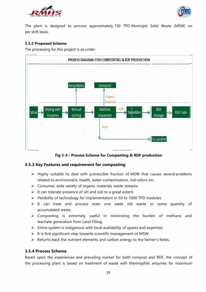
3.5.2 Proposed SchemeThe processing for this project is as under‐
Fig 3-3-: Process Scheme for Composting & RDF production
3.5.3 Key Features and requirement for composting
Highly suitable to deal with putrescible fraction of MSW that causes several problemsrelated to environment, health, water contamination, mal‐odors etc.
Consumes wide variety of organic materials waste streams It can tolerate presence of silt and soil to a great extent. Flexibility of technology for implementation in 50 to 1000 TPD modules It can treat and process even one week old waste or some quantity of
accumulated waste. Composting is extremely useful in minimizing the burden of methane and
leachate generation from Land Filling. Entire system is indigenous with local availability of spares and expertise. It is first significant step towards scientific management of MSW. Returns back the nutrient elements and carbon energy to the farmer’s fields.
3.5.4 Process SchemeBased upon the experiences and prevailing market for both compost and RDF, the concept ofthe processing plant is based on treatment of waste with thermophilic enzymes for maximum
20
drying. Due to biological digestion of organic matter compost will be formed. Compost, RDF andrecyclables are separated in various steps of manual Orting and mechanical separation. Theprocess reject/inert will be regularly removed and transported to the adjacent landfill site.In the proposed RDF cum compost processing facility, MSW will be composted for period ofabout 25‐30 days. Bio inoculums will be sprayed over the MSW which will help in achievingmoisture content of about 20% in period of about 8‐10 days and also suppressing the odor. Thedried MSW will be processed in various sections of processing facility where fractions of RDF(combustibles), Recyclables (metal, rubber, cans etc.), Compost and Inert will be separated.
MSW processing unit would have following steps:
A. UnloadingA ramp with suitable gradient will be provided along the length of the composting pits, whichwill be used as an unloading platform for incoming vehicles loaded with garbage.Compactors/trucks (as applicable) will enter through this ramp only and unload the garbageinside the pits. The height of ramp will be decided as per economic design.
B. DryingAs per the concept of drying, 28 no. of pits (of RCC) will be constructed for retention of 25 daysmaterial. Waste will be unloaded inside this pit. Proper aeration will be provided by tumbling thewaste after 3 to 4 days to maintain aerobic conditions.Owing to the criticality of leachate management, the whole composting section (pits) will be atground level only, where the drains can easily be cleaned at regular intervals to avoid choking andputrefaction.Sufficient quantity of decomposing microbial cultures (inoculum & sanitizer) will beinoculated at this point with sprayer to reduce odor and enhance digestion. Bio‐inoculum will besprayed over the MSW in order to reduce moisture level in MSW. The process will be bacteriainduced, leading to temperature rise (550C to 600C). This kind of exothermic phase ensures oozingout of intercellular (imbibed moisture) thereby drying of waste. This system is much better thansurface drying through hot air; it also works out cost effective. Drastic moisture (up to 20%)reduction leading to free flow ability of waste and loosening of material for easy shreddingis expected. The proposed bio drying process is called Bio Thermal Stabilization Method(BTSM) is based on the principles of raw material constituents of waste. The constituentsare to be seen from bio chemical composition such as content of cellulose, hemi cellulose, lignin,protein, lipids, waxes etc. When such waste is subjected to bacterial feeding enzymatic reaction, itwill induce Mesophelic (200C to 450C) temperature range followed by thermophilic (550C to 650C)temperature range. Mesophilic microbes break down simple sugars and thermophilic microbesbreak down break down proteins and some complex carbohydrates. The process starts within 36 to48 hours of inoculation and continues till oxygen is available in the biomass. The total time requiredto achieve 20% moisture level is about 8‐10 days. The composting pits will be turned every third or
21
fourth day for increasing the rate of reaction with thermophilic enzymes leading to faster drying.Moisture will also be supplemented at required levels after leachate treatment. Thecomposting heap will be stabilized in about 25 days, when it is shifted to the screening section.On 26th day, the completely digested waste will then be conveyed to a manual sorting belt throughgrab cranes. For the ease of handling this waste to further process line, grab cranes will be providedalong the length of this section.
C. SegregationA long manual sorting will be provided to remove inert, very heavy or large sized material andcutting of packed garbage bags in order to promote proper digestion of waste byenzymes. The manually segregated waste after magnetic separation will then be passedthrough a ballistic separator with twin screens of mesh size approx. to 100 mm & 10 mmwhich will separate the mass into fuel fluff and compostable material.MSW will be fed in the centre of this ballistic separator through a hopper/chute and will bescreened in two stages. There will be four outputs from this equipment.The oversize material from 100 mm size screen will be taken to a shredder where it will beconverted into fluff of 50‐80 mm size and to storage thereafter. Material of size between 60 to100 mm will be directly taken into RDF storage.
D. RefiningThe undersize material coming out from 10 mm screen will be fed to 4 mm trammel screen. Oncethis equipment screens material, it gradually feeds the same to the consecutive equipmentat a controlled rate. The screened material is sent to the Destoner/vibratory screen whichremoves heavy impurities such as glass, metals, sand, silica etc. from the organic manure. Themagnetic separator in the production line will take care of all kinds of ferrous impurities in thecompost. The screened and refined Compost is stored in curing section for about 10‐15 days forfurther stabilization and moisture control. Cured material is then packed in the mechanizedpacking section to do the bagging, weightment and stitching of various sizes of bags andfinally stacked in the finished product store by using a belt conveyor.A permanent truss‐shed will be provided over processing area, composting area andunloading area with suitable height (as required for mounting grab cranes).
3.5.5 Detail DescriptionA. Composting
Pit management SystemTruck carrying MSW will be visually inspected before it goes to weighbridge. Theweighbridge operator then instructs the driver to proceed to the tipping floor where MSW isunloaded directly into the composting pits. It is kept there for 25 days where it is digestedwith the help of Enzyme & aeration.The waste into these pits is periodically turned (normally once a week) using grab cranes to provideproper aeration and temperature control. The composting heap is stabilized before it is shifted
22
to the screening plant for removal of the inert and non‐composted matter. Duringdigestion, leachate is added to these pits using water tanker to maintain requisite moisturelevel. The culture and sanitizer are added to remove odor and for digestion. Sufficientquantity of decomposing microbial cultures (inoculums & sanitizer) will be inoculated at this pointwith sprayer to reduce odor and repel vectors. Moisture will also be supplemented at requiredlevels. The thoroughly mixed waste is then kept for the biologic decomposition with this; bacterialactivity starts within 2‐3 days. Inside temperature of the windrow may go up to 65oC. After this, thewaste is then taken to manual sorting where all the large size construction debris and recyclableitems are separated.
It is then fed to the twin screen ballistic separator for intermediate coarse segregation screening.Multi stage screening system is adopted to achieve maximum screening efficiency usingtrammel. Cascading action inside this ensures better screening of the lumpy and highlyheterogeneous municipal solid waste.
Screened material coming out of this section is uniform in texture and contains semi–stabilized organic compost. This material needs further stabilization so it is transferred to the curingsection.
The undersize material coming out from 10 mm screen will be fed to 4 mm trammel screen. Oncethis equipment screens material, it gradually feeds the same to the consecutive equipmentat a controlled rate. The screened material is sent to the Destoner/ vibratory screen whichremove heavy impurities such as glass, metals, sand, silica etc. from the organic manure. Themagnetic separator in the production line will take care of all kinds of ferrous impurities in thecompost.As per compost quality norms nationally (FCO) and internationally, the compost should bebelow 4 mm average particle size and it should not contain impurities such as glass, plastic,other inert material etc.
B. RDF Processing PlantWaste SegregationThe oversize material from 100 to 10 mm screen is first stored as RDF fluff after properstone and inert separation. The material above 100 mm is fed to primary shredder where its sizeis reduced to 50 ‐ 80 mm.
ShredderThe primary shredder (fed by the moving floor feeder) cuts the material to a size of < 80 mmallowing the after coming from ballistic separator to work optimally. It is an extremely heavyconstruction, h i g h capacity, des igned for industrial purposes . The machine has a largenumber of features to ensure reliable and economic operation, for example easilyexchangeable knives etc.
23
3.5.6 Leachate Treatment PlantLeachate is the water‐based complex liquid, comprising of innumerable organic and inorganiccompounds, which percolates through garbage heaps and accumulates at the bottom. Thewater from interstitial moisture of the decomposing waste and also due to precipitationsubsequently moves through the waste deposit collecting the leached chemicals therebyforming leachate. Leachate contains a host of chemicals that may be toxic to both humans andenvironment. Also, the high Bio‐chemical Oxygen Demand (BOD) of leachate makes itstreatment inevitable.Leachate management follows the hierarchal procedure comprising of Leachate Avoidance: by keeping the compost as dry as possible. Leachate Minimization: by re‐circulating the leachate onto the composting heap. Leachate Collection & Treatment: by incorporating proper drainage system to
collect the leachate from the bottom and efficiently treating to comply with thestandards before disposing the treated liquid waste into streams.
3.5.7 Leachate Treatment PlantA. Drainage System:
The leachate drainage system is responsible for the collection and transport of the leachatecollected inside the liner. Leachate collection systems are installed above the liner andusually consist of a piping system sloped to drain to a central collection point where apump is located. The pipes and conduits must be captive of bearing the load they aresubjected to, since they are placed beneath the composting heap.
B. Leachate treatment PlantBased upon the analyzed characteristics of the leachate collected, the treatment units areprovided.Treatment Process Influent Leachate Storage Tank: For collecting and storing the leachate generated. Helps
in flow equalization and allows controlled flow of leachate per treatment cycle. Mesh Screens: Removes unwanted solid particles that may cause clogging of
the drainage system and also leads to wear & tear of further treatment units. Oil & Grease Trap: Efficient removal of oil & grease produced from decomposing
organic matter. Moving Bed Bio-film Reactor: The inoculums are added after studying the characteristic
of leachate to be treated. The bacteria/activated sludge grow on the internal surface ofthe carriers. The bacteria break down the organic matter from the waste water. Theaeration system keeps the carriers with activated sludge in motion. Only the extra amountof bacteria growth, the excess sludge will come separate from the carriers and will flowwith the treated water towards the final separator. Blowers: aids biological growth andfacilitate waste reduction.
Secondary Clarifier: Here, the supernatant treated water is collected and stored in the
24
sump tank, while the settled sludge received in the hopper attached at the bottom of theclarifier is to the sludge drying beds.
Sump Tank: temporarily stores the water and provides further aeration via blower. Carbon filter and Sand Filter: Provides proper filtration from any unwanted particles. Sludge Disposal: Sludge containing the carriers is dried at the sludge drying beds
and used as manure for gardening. The treated water is re‐circulated by spraying onto the composting heap in order to
maintain its moisture content. Thus, the treatment plant becomes a Zero Discharge Unit.
C. Design of Leachate Collection SystemLeachate Collection systemThe primary function of leachate collection system is to collect and to convey the leachate outof the landfill unit and to control the depth of the leachate above the liner. As perUSEPA Manual the leachate collection system should be designed to maintain a leachate depthor less above the liner. The design leachate head is very important as flow of leachate throughimperfections in the liner system increases with an increase in leachate head above the liner.Maintaining a low leachate level above the liner helps to improve the performance ofthe composite liner system. The main components of leachate collection system are leachatecollection tank, feeder mains and header main.
Leachate Collection NetworkLeachate Collection Network comprising header pipe and feeder pipe/ laterals has beenproposed. The feeder pipes shall be of 200 mm diameter at a spacing of 10 m centre to centre at aslope of 2 per cent and connected to header pipe. Similarly the header pipe shall be 270 mmdiameter at a slope of 2 per cent connected to leachate collection tank.
Leachate Collection SumpThe purpose of leachate collection tank is to collect the leachate from header pipe and activelandfill area. The leachate collection tank would be supported by the pump to lift the collectedleachate.
Feeder and Header Pipe MaterialA leachate collection system is a network consisting, 200 mm diameter feeder pipe at lateralspacing of 10m connected to 270 mm diameter header pipe. The pipes shall beHDPE perforated pipes with sufficient strength and should be safe from particulate andbiological clogging and deflections. The generated leachate shall be transported to LeachateTreatment Plant (LTP) and treated to as per prescribed norms prior to its final disposal.
Procedure for Landfill MeasurementAll the inert material will be stored at site other than SLF. SLF will be surrounded by barbedwires and a lock will be provided. ULB can depute their concern person on weekly basis tocheck and dump the material in SLF.
25
3.5.8 Sanitary land-fill for rejectsThere will be a dedicated engineered sanitary landfill site which will handle the rejects from theMSW processing facility. Deposition of inert in conical heaps over the landfill site and spreadingthese heaps using a tracked bull dozer is a low cost and easy option.The landfill development strategy for MSW management is formulated to satisfy the regulatoryrequirements of MoEF and the guidelines of CPHEEO, with the following objectives- Environmental Protection and protection from the flooding Physical Acceptability Technical Standards of Site Engineering Required Operational and Management Standards Desirable Appropriateness and Sustainability of the Method Volumetric Capacity of the Site Longevity of the Method and Cost Effectiveness of the Recommended Measures
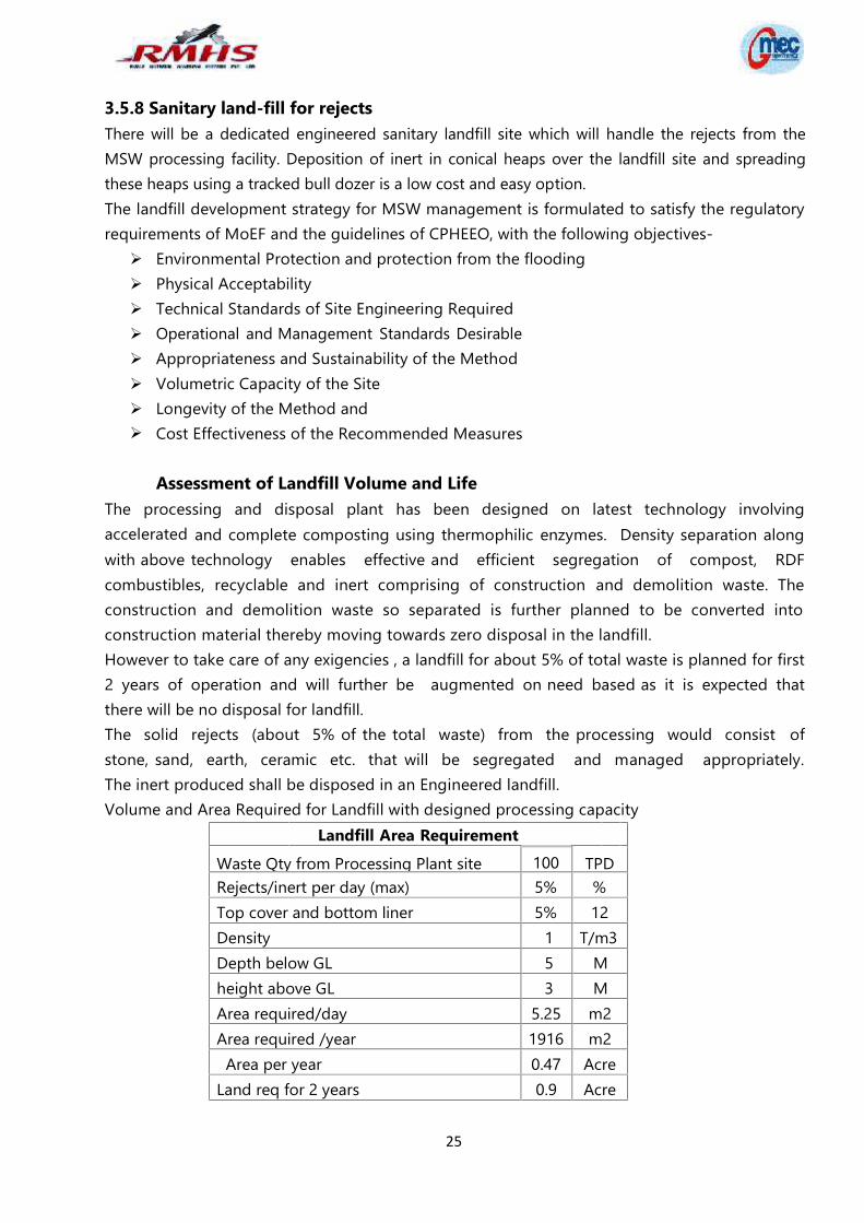
Assessment of Landfill Volume and LifeThe processing and disposal plant has been designed on latest technology involvingaccelerated and complete composting using thermophilic enzymes. Density separation alongwith above technology enables effective and efficient segregation of compost, RDFcombustibles, recyclable and inert comprising of construction and demolition waste. Theconstruction and demolition waste so separated is further planned to be converted intoconstruction material thereby moving towards zero disposal in the landfill.However to take care of any exigencies , a landfill for about 5% of total waste is planned for first2 years of operation and will further be augmented on need based as it is expected thatthere will be no disposal for landfill.The solid rejects (about 5% of the total waste) from the processing would consist ofstone, sand, earth, ceramic etc. that will be segregated and managed appropriately.The inert produced shall be disposed in an Engineered landfill.Volume and Area Required for Landfill with designed processing capacity
Landfill Area RequirementWaste Qty from Processing Plant site 100 TPDRejects/inert per day (max) 5% %Top cover and bottom liner 5% 12Density 1 T/m3Depth below GL 5 Mheight above GL 3 MArea required/day 5.25 m2Area required /year 1916 m2
Area per year 0.47 AcreLand req for 2 years 0.9 Acre
26
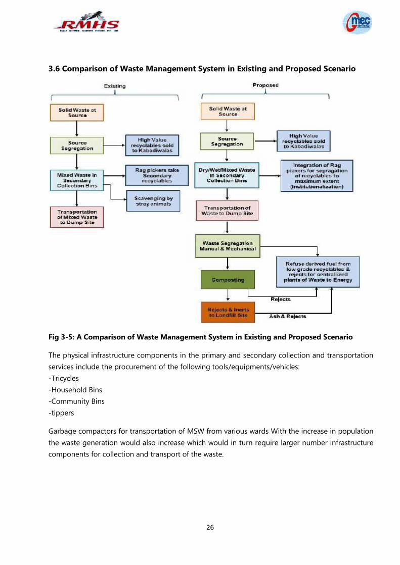
3.6 Comparison of Waste Management System in Existing and Proposed Scenario
Fig 3-5: A Comparison of Waste Management System in Existing and Proposed Scenario
The physical infrastructure components in the primary and secondary collection and transportationservices include the procurement of the following tools/equipments/vehicles:-Tricycles-Household Bins-Community Bins-tippers
Garbage compactors for transportation of MSW from various wards With the increase in populationthe waste generation would also increase which would in turn require larger number infrastructurecomponents for collection and transport of the waste.
27
CHAPTER 4 - SITE ANALYSIS
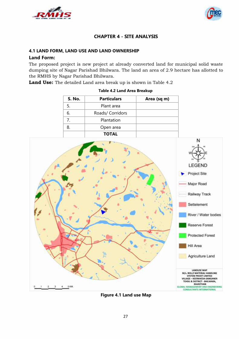
4.1 LAND FORM, LAND USE AND LAND OWNERSHIPLand Form:The proposed project is new project at already converted land for municipal solid wastedumping site of Nagar Parishad Bhilwara. The land an area of 2.9 hectare has allotted tothe RMHS by Nagar Parishad Bhilwara.Land Use: The detailed Land area break up is shown in Table 4.2
Table 4.2 Land Area Breakup
S. No. Particulars Area (sq m)5. Plant area6. Roads/ Corridors7. Plantation8. Open area
TOTAL
Figure 4.1 Land use Map
28
Land Ownership:
Land is located at Khasra No- 2031, Village- Keerkheda (Sanganer), Tehsil and District- Bhilwara(raj.)The proposed land an area of 2.9 hectare for municipal Solid waste management is a govt. land ofNagar Parishad Bhilwara which has been granted to Rollz Material Handling System Pvt. Ltdon lease vide letter no. N.P.B./Works/2016-17/8965 dated 01.12.2016.
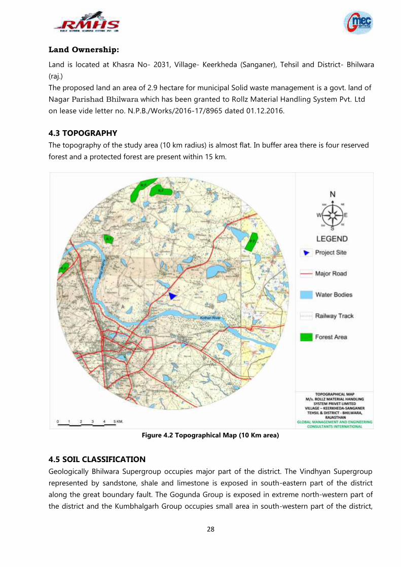
4.3 TOPOGRAPHYThe topography of the study area (10 km radius) is almost flat. In buffer area there is four reservedforest and a protected forest are present within 15 km.
Figure 4.2 Topographical Map (10 Km area)
4.5 SOIL CLASSIFICATIONGeologically Bhilwara Supergroup occupies major part of the district. The Vindhyan Supergrouprepresented by sandstone, shale and limestone is exposed in south-eastern part of the districtalong the great boundary fault. The Gogunda Group is exposed in extreme north-western part ofthe district and the Kumbhalgarh Group occupies small area in south-western part of the district,
29
both belonging to Delhi Supergroup. The Aravalli Supergroup exposed in western part of thedistrict is represented by Dovda Group.
4.6 CLIMATE DATA FROM SECONDARY SOURCESThe project falls in dry climate area. During the summer season it is very hot, but far less than theother cities of Rajasthan. The summer season spans between the months of April and June. May isthe hottest month of the year when, the temperature raises up to 42° - 43° Celsius. During thisperiod the maximum temperature is approximately 43º Celsius and the minimum temperature isaround 28º Celsius. The winters are cool and pleasant spanning between November and February.The temperature during the winter season approximately varies within the range of 23° C(maximum) to 8° C (minimum). January is the coldest month of the season with temperaturedropping to nearly 8 degrees Celsius. The average annual rainfall is around 574 mm. The averagehumidity of is ~53 per cent. The topography of the study area is almost flat.
4.7 SOCIAL INFRASTRUCTURE AVAILABLE
Social infrastructure like hospitals, educational facilities, temple, community centre, roads,
telecommunication and others similar are available within 10 km radius.
30
CHAPTER 5 ENVIRONMENTAL MITIGATION MEASURESProposed construction and operation of the project comprising various activities may have someimpacts on one or more environmental components. Probable impacts during various phases ofthe project lifecycle on the environmental and socioeconomic components are evaluated.In consideration to the prevailing site features and the proposed Integrated Municipal Solid WasteManagement Facilities, outlined in earlier Chapters, it is necessary to ensure that the proposedplant and facilities would be adequately designed with necessary environment protectionmeasures. This Chapter accordingly outlines the environment protection measures for the proposedIntegrated Municipal Solid Waste management at Bhilwara site comprising of Compost Plant andSanitary Landfill. During project implementation period special emphasis would be made onmeasures to minimize leachate or effluent generation and dust control at source. The sources andtypes of pollution with broad level mitigation measures have been outlined in the followingsections.
5.1 AIR POLLUTION CONTROL MEASURESComparing the baseline air quality along with predicted increase in SPM, the increase would bestill within the stipulated ambient air quality levels for the residential areas. However, followingmitigation measures are proposed to reduce the dust levels in the ambient air environment: Maintaining and/or re‐establishment of a grass cover on area where there is no
on‐going activity Frequent watering of unsealed roads and stockpile area‐ cover material Blacktop of the roads as and when they are settled and ready for the same Repair, relaying of blacktop roads from the landfill area to the main road Using dust control sprays during loading and unloading of wastes Ceasing dust generating activities during high wind times Minimizing working distances for internal transport of wastes Periodical monitoring of ambient air quality for all relevant parameters as indicated
in the monitoring plan Odor control by rapid stabilization and disposal of wastes at the earliest along with
daily cover placementThe above mentioned measures will help in minimizing the fugitive emissions and dust.
5.2 WATER POLLUTION CONTROL MEASURESConstruction Phase: During the construction phase, a septic tank shall be provided totreat the domestic wastewater generated due to labor settlements. Temporary facility wouldhave impermeable flooring and proper leachate collection arrangement.Operation Phase: During initial composting i.e. for about 3 days, leachate will be released. Thisleachate shall be utilized to maintain required moisture level in composting pits. Howeverthe excess leachate discharged shall be collected and treated before draining.The small quantities of leachate generated will be collected in the sump and treated in
31
leachate Treatment Plant which will comprise of a settling tank, aeration system andtreatment with suitable chemicals. This treated leachate will be used for gardening.Excessive leachate generation in monsoon season will be combated by covering thesub‐cells of the facility during rain with HDPE sheets and ensure that no water comes in contactwith the waste.
5.3 SOLID WASTE DISPOSAL MANAGEMENT PLANThe processing and disposal plant has been designed on latest technology involving accelerated andcomplete composting using thermophilic enzymes. Density separation along with above technologyenables effective and efficient segregation of compost, RDF combustibles, recyclables andinert comprising of construction and demolition waste. The construction and demolition waste soseparated is further planned to be converted into construction material thereby moving towardszero disposal in the landfill.However to take care of any exigencies, a landfill for about 5% of total waste is planned for first 2years of operation and will further be augmented on need based as it is expected thatthere will be no disposal for landfill.The solid rejects (about 5% of the total waste) from the processing would consist of stone,sand, earth, ceramic etc. that will be segregated and managed appropriately. The inertproduced shall be disposed in an Engineered landfill.The proposed facility will have seven days storage for RDF fluff. To mitigate potential fireproblems, adequate measures such as water hydrants with adequate pressure or dry powder typewill be provided.
5.4 NOISE CONTROL MEASURESThe sources of noise generation in the facility will be from the generators, heavy earthmachinery and plant machinery in addition to the vehicular movement. While all noise levels arewell within the acceptable limits the following strategies would be adopted to further minimizethe noise levels: Maintaining the site machinery in good operating condition Regular maintenance of systems and installation of noise control equipment wherever
required Development of green belt all around the site Periodical monitoring of noise levels
5.5 ECOLOGY OF THE AREASite clearing or operational activities would not impact the ecology of the area adversely, sincethere are no known rare, endangered or ecologically significant animal and plant species in thearea. There is four reserved forest and a protected forest are present within 15 km. In fact thescientific processing and land filling would have a beneficial impact on the surrounding terrestrialand aquatic ecology.
32
5.6 GREEN BELT DEVELOPMENTA green belt is provided to mitigate various emissions. Green belts are wide strip of trees andshrubs planted in rows to reduce air velocity there by facilitating settling of the particles on theleaf surfaces and allowing absorption of the pollutant gases. It also serves to cool theatmosphere by transpiration from the leaf surface and also provide habitat for birds, reptiles andinsects. The advantages of a green belt are given below: Greenbelts are important habitats for birds and animals, which add to the aesthetic value
of the environment. Generally, birds prefer to make their habitat, nest, on trees. Furthertrees provide shade and hiding places to wild life.
It helps to restore the ecological balance. It helps in prevention of soil erosion. It helps to improve the aesthetics in the area. It also diminishes noise pollution by absorbing high degree of noise due to their Spongy
foliar crown
A. Selection criteria of Plant species for Green belt developmentThe selection of plant species for the development depends on various factors such asclimate, elevation and soil. The list of plant species that can be suitably planted andhaving significant importance are provided below. The plants should exhibit the followingdesirable characteristic in order to be selected for plantation. The species should be fastgrowing and providing optimum penetrability. The species should be wind‐firm anddeep‐rooted.The species should form a dense canopy. As far as possible, the species should be indigenousand locally available Species tolerance to air pollutants. The species should be permeable to help create air turbulence and mixing within the
belt. There should be no large gaps for the air to spill through. Trees with high foliage density, leaves with larger leaf area and hairy on both the
surfaces. Ability to withstand conditions like inundation and drought. Soil improving plants (Nitrogen fixing, rapidly decomposable leaf litter). Attractive appearance with good flowering and fruit bearing. Bird and insect attracting tree species. Sustainable green cover with minimal maintenance
B. Suggested Trees For Peripheral Green Belt DevelopmentFollowing species can be used in a greenbelt to serve as noise breakers:
S No Local Name Botanicnl Name Family1. Aam Mangifera indica Anacardiaceae
2. Sitaphal Annona squamosal Annonaceae
33
3. Tendu Diospyros melanoxylon Ebenaceae
4. Jamun Syzygium cuminii Myrtaceae
5. Safeda Eucalyptus terelicornis Myrtaceae
6. Shisham Dalbergia sissoo Fabacea
7. Neem Azadirachta indica. Meliaceae
8. Babool Acacia arabica Meliaceae
9. Bengallia-Babool Acacia auriculifornis Meliaceae
10. Siris Albizzia lebbek Meliaceae
11. Khejri Prosopis cineraria Meliaceae
12. Vilayati-babool Prosopis juliflora Meliaceae
13. Pipal Ficus religiosa Meliaceae
14. Gulmohar Delonix regia. Caesalpiniaceae
15. Imli Tamarindus indica Caesalpiniaceae
5.7 HEATH AND SAFETY MANAGEMENTThe health and safety of all those who work at the Plant shall be ensured by: Assessing the risk of all work activities, recording the significant findings and developing
method statements a r e as appropriate. Providing and maintaining safe plant and systems of work, together with appropriate
personal protective equipment Minimizing risks associated with hazardous substances including waste to be
processed, materials used and the by‐products of waste treatment processes Minimizing risks associated with other occupational health risks including noise,
vibration and manual handling Maintaining the Plant in safe condition including as regards workplace transport and
fire risks Providing appropriate information, instruction, training and supervision to those
working at the Plant or visiting the Plant, including information and training withregard to the emergency procedures
Implementing effective systems for active and reactive monitoring of compliance,including by inspections, audits and incident/ near miss investigation
All personnel attending site, shall be equipped with Long Sleeves work clothes, SafetyHelmet, Safety Boots, Hi‐Vis vest or jacket and Safety Glasses which shall be worn at alltimes whilst working in the construction area.
Equipment safety rulesAll necessary tools and equipment, including personal protective equipment, shall be properlymaintained. Defective tools and equipment shall be repaired or replaced immediately.
34
All equipment shall be used only be employees who have been properly trained and are otherwise competent to use the tools and equipment safely Only authorized personnel shall operate heavy‐duty equipment/ equipment/
machinery in the Plant. Equipment can only be started when the followingtwo conditions are fulfilled:
Comply with the applicable Permit‐To‐Work System Local check has been carried out to confirm that the equipment is in working condition
and that no one is near the equipment. For equipment with local on/ off switch, it shouldalways be started locally. Unauthorized possession of equipment switching keys by anyperson is prohibited. No bypassing is allowed unless approval given by the authorizedperson.
Hazards caused by moving or rotating parts of machines are covered with providing anelectrical/ pneumatic lockout procedure.
The allowable safety load limit of a machine, a working tool, or piece of equipment maynot be exceeded. Tools, equipment, and machinery shall not be altered in any mannerthat would reduce their original safety limit. Any and all changes tomachines, equipment and/or materials must be approved by an official inspection unit.
35
CHAPTER 6- REHABILITATION AND RESETTLEMENT (R&R) PLAN
The proposed project is new project at already converted land for municipal solid wastedumping site of Nagar Parishad Bhilwara. The proposed land an area of 2.9 hectare formunicipal Solid waste management is a govt. land of Nagar Parishad, Bhilwara which has beengranted to Rollz Material Handling System Pvt. Ltd on lease vide letter no. N.P.B./Works/2016-17/8965 dated 01.12.2016. Land is located at Khasra No- 2031, Village- Keerkheda (Sanganer),Tehsil and District- Bhilwara (raj.)Thus rehabilitation and resettlement plan in not applicable in this particular project.
36
CHAPTER 7- PROJECT SCHEDULE & COST ESTIMATES
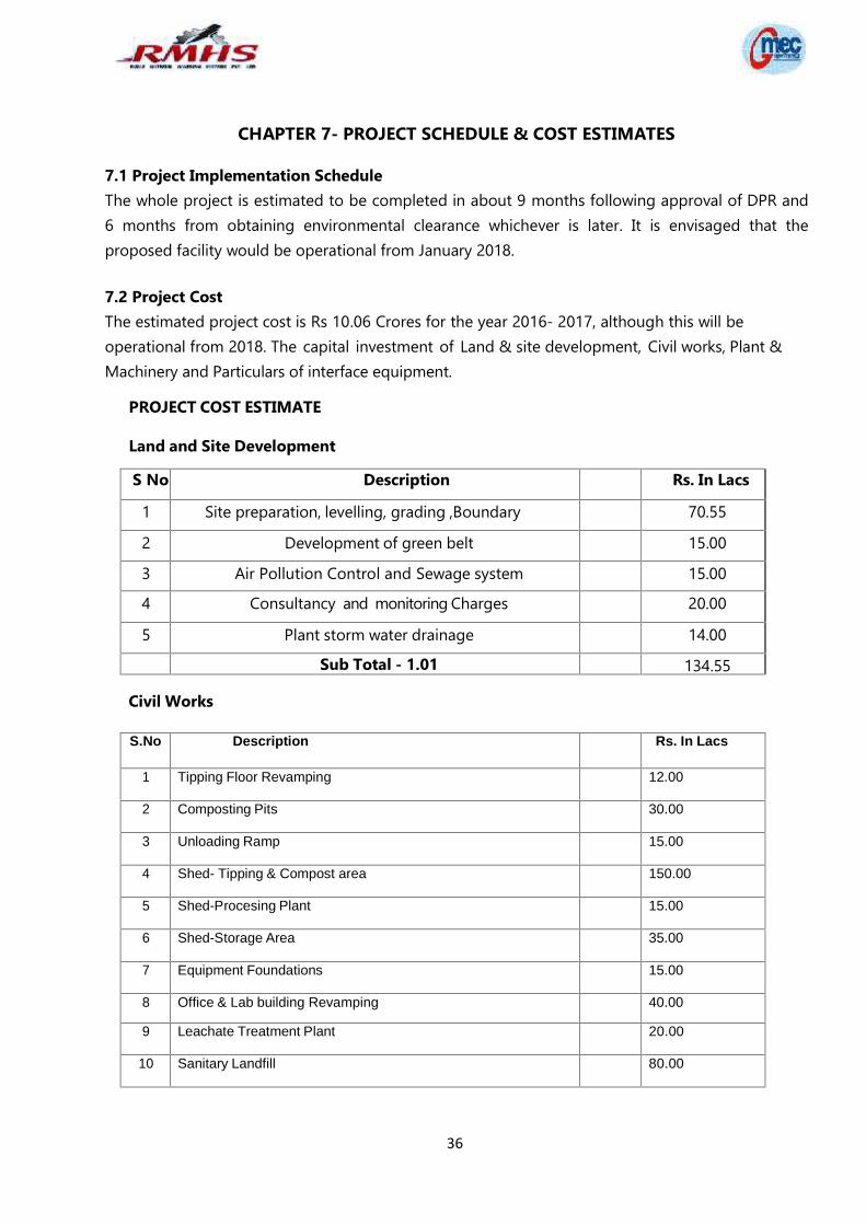
7.1 Project Implementation ScheduleThe whole project is estimated to be completed in about 9 months following approval of DPR and6 months from obtaining environmental clearance whichever is later. It is envisaged that theproposed facility would be operational from January 2018.
7.2 Project CostThe estimated project cost is Rs 10.06 Crores for the year 2016- 2017, although this will beoperational from 2018. The capital investment of Land & site development, Civil works, Plant &Machinery and Particulars of interface equipment.
PROJECT COST ESTIMATE
Land and Site Development
S No Description Rs. In Lacs
1 Site preparation, levelling, grading ,Boundary 70.55
2 Development of green belt 15.00
3 Air Pollution Control and Sewage system 15.00
4 Consultancy and monitoring Charges 20.00
5 Plant storm water drainage 14.00
Sub Total - 1.01 134.55
Civil Works
S.No Description Rs. In Lacs
1 Tipping Floor Revamping 12.00
2 Composting Pits 30.00
3 Unloading Ramp 15.00
4 Shed- Tipping & Compost area 150.00
5 Shed-Procesing Plant 15.00
6 Shed-Storage Area 35.00
7 Equipment Foundations 15.00
8 Office & Lab building Revamping 40.00
9 Leachate Treatment Plant 20.00
10 Sanitary Landfill 80.00
37
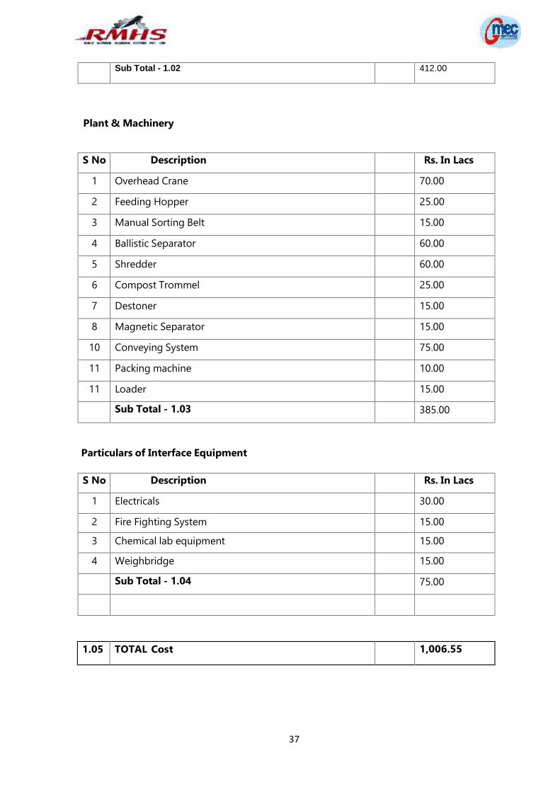
Sub Total - 1.02 412.00
Plant & Machinery
S No Description Rs. In Lacs
1 Overhead Crane 70.00
2 Feeding Hopper 25.00
3 Manual Sorting Belt 15.00
4 Ballistic Separator 60.00
5 Shredder 60.00
6 Compost Trommel 25.00
7 Destoner 15.00
8 Magnetic Separator 15.00
10 Conveying System 75.00
11 Packing machine 10.00
11 Loader 15.00
Sub Total - 1.03 385.00
Particulars of Interface Equipment
S No Description Rs. In Lacs
1 Electricals 30.00
2 Fire Fighting System 15.00
3 Chemical lab equipment 15.00
4 Weighbridge 15.00
Sub Total - 1.04 75.00
1.05 TOTAL Cost 1,006.55