Embed Size (px)
Citation preview
Surface and Coatings Technology 166(2003) 17–23
0257-8972/03/$ - see front matter� 2002 Elsevier Science B.V. All rights reserved.PII: S0257-8972Ž02.00719-3
Evaluation of through-porosity of HVOF sprayed coating
Jin Kawakita*, Seiji Kuroda, Toshiaki Kodama
National Institute for Materials Science, 1-2-1 Sengen, Tsukuba, Ibaraki 305-0047, Japan
Received 7 May 2002; accepted in revised form 19 September 2002
Abstract
Anticorrosion coatings must be impermeable to protect steel structures in marine environments. We evaluated the through-porosity of HastelloyC high-velocity oxyfuel(HVOF) sprayed coatings by quantitatively analyzing dissolved substances derivedfrom coated steel during immersion in HCl solution. This enabled us to detect slight amounts of through-pores, which dependedon the coating thickness and on the coating’s stacking structure. It also enabled us to separately calculate both coating through-porosity and corrosion resistance when electrochemical measurements could not selectively detect either of these properties.� 2002 Elsevier Science B.V. All rights reserved.
Keywords: High-velocity oxyfuel(HVOF); Nickel alloy; Through-porosity; Inductively coupled plasma(ICP) atomic emission spectrometry;Electrochemical
1. Introduction
One of the objectives of the ‘Ultra Steel’ researchproject started in 1995 at Japan’s National Institute forMaterials Science was to improve the corrosion resis-tance of structural steels in marine environments bydepositing anticorrosion materials through thermalspraying. The sprayed coating is expected to be used inon-site repair of damaged clad steel and as an alternativeto clad steel. Such a coating must be both impermeableand highly corrosion-resistant. We used high-velocityoxyfuel (HVOF) spray because it enabled us to deposita dense coating with comparatively little change insprayed particle properties during spraying.Coatings of HVOF sprayed AISI316L stainless steel
and HastelloyC nickel-base alloy have been studied todetermine the relationship between spray conditions andproperties such as porosity, oxygen content, and corro-sion resistancew1–4x.If a sprayed coating has through-porosity, seawater
may permeate the coating beneath the splash zone of amarine structure and reach the interface between thecoating and substrate. When a conductive solution con-tacts different conductive material, it forms what is
*Corresponding author. Tel.:q81-298-59-2445; fax:q81-298-59-2401.
E-mail address: [email protected](J. Kawakita).
called a galvanic cell, where a combination of the noblecoating and the less-noble substrate accelerates substratecorrosion more than, for example, a bare substrate withthe same surface area.The porosity of most HVOF sprayed coatings has
been measured by image analysis of their cross-sectionalviews w5–8x. The accuracy of this method is not suffi-ciently high because the cross-section aspect dependssignificantly on sample preparation. Other methods tomeasure porosity include computed simulationw9x andmercury intrusion porosimetryw1,10x. Although mercuryintrusion porosimetry measures open pores comparative-ly precisely, it could not determine the open porosity ofHVOF sprayed HastelloyC coatings because these coat-ings had extremely low open porosity below the detec-tion limit for mercury intrusion porosimetry. Mercuryporosimetry also requires that a coating be at least 1mm thick and that the coating be stripped from thesubstrate. We thus required detection with higher sensi-tivity to estimate through-pores.We evaluated the through-porosity of HastelloyC
HVOF sprayed coatings on low-carbon steel substratesto determine their dependence on coating thickness andon combustion pressure in spraying. To evaluate thethrough-porosity, we used inductively coupled plasma(ICP) emission spectroscopy to analyze dissolved sub-stances derived from through-pores after dissolution

18 J. Kawakita et al. / Surface and Coatings Technology 166 (2003) 17–23
Table 1Spray conditions and properties of the HastelloyC coatings
Unit HP SP
Fuel (kerosene) flow rate dm min3 y1 0.47 0.38Oxygen flow rate dm min3 y1 1080 860Combustion pressure MPa 0.86 0.68Fuelyoxygen ratio – 0.82a
Barrel length mm 102Powder feed rate g miny1 60Torch velocity mm sy1 700Spray distance mm 380Powder feed gas – Nitrogen(N )2Film thickness mm 50–400Open porosity vol.% 0 -0.1Oxygen content wt.% 1.10 0.63
1.0 corresponds to the stoichiometric mixture ratio.a
Fig. 1. Variation with immersion time in dissolution amount of Fefrom various specimens in 0.5 M HCl:s, HastelloyC coating(SP,385 mm) on SS400;d, HastelloyC coating(SP, 400 mm) onHastelloyC276;j, HastelloyC276 plate; andh, SS400 plate.
from the steel substrate in corrosion during immersionin hydrochloric acid (HCl). We then compared theamount of through-porosity determined by chemicalanalysis to results of electrochemical measurement.
2. Experimental
HastelloyC was coated by HVOF spraying with aTAFA apparatus(JP-5000). The chemical compositionof the HastelloyC(TAFA 1268F) feedstock was asfollows: Mo 16.95, Cr 16.57, Fe 6.21, W 4.52, Mn 0.72,Co 0.31, Si 0.73, and Ni balance. We varied combustionpressure and the traverse number of the spray gun.Combustion pressure was 0.68 MPa, termed standardpressure(SP), and 0.86 MPa, termed higher pressure(HP) below. Table 1 lists combustion pressure andprimary spray conditions recommended by the manufac-turer. The substrate materials we used were JIS SS400low-carbon steel and HastelloyC276 nickel base alloy.The substrate was 2t=50=100 mm. Before spraying,substrates were blasted with alumna grit and degreasedultrasonically in acetone. Coatings with four coatingthicknesses from 50 to 400mm were obtained bychanging the traverse number. Other properties of resul-tant coatings are listed in Table 1. We measured openporosity using mercury intrusion porosimetry and deter-mined the oxygen content of the coating using inert-gasfusion.Coated plates were cut into 2.5 cm sections and2
repeatedly cleaned ultrasonically in acetone and ion-exchanged water.We chemically analyzed and electrochemically meas-
ured the through-porosity of the HVOF sprayed coatingas follows: a coated specimen was connected with astainless rod and used as an electrode whose surface,except for 2 cm of the sprayed surface, was covered2
with silicone resin. For comparison, an electrode ofSS400 and HastelloyC276 bulk plates was prepared thesame way. The electrode was immersed at 300 K in 0.5mol dm of HCl, used to avoid filling through-porosity–3
with solid corrosion products and to include chlorideions with almost the same concentration as in seawater.At predetermined times, 5 ml of test solution wassampled and iron(Fe) and nickel (Ni) elements dis-solved in sampled solutions determined by ICP atomicemission spectrometry using an analyzer(SPS 3000,Seiko Instruments Inc.). Both elements were the baseof the substrate and coating metals. We measured dis-solved ions once for the same experimental conditions,but twice for coatings approximately 400mm thick. Theresults for the coatings which were approximately 400mm thick, were consistent and measurement was satis-factorily replicable. We obtained the corrosion potentialof the electrode and its polarization resistance, whichindicates the degree of corrosion resistance and wasmeasured by alternating current(a.c.) impedancew11xusing a corrosion monitor(Model CT-5, Riken Denshi).The electrode potential was referenced to the standardpotential of the AgyAgCl electrode in a saturated KClsolution.
3. Results and discussion
3.1. Chemical analysis
Fig. 1 shows typical variations over time in elementalFe dissolution from different specimens immersed inHCl solution. Dissolution is represented per geometricsurface area of the exposed sprayed face(2 cm ).2
Differences were observed in Fe dissolution amongspecimens even for 30 min immersion, i.e. in initial

19J. Kawakita et al. / Surface and Coatings Technology 166 (2003) 17–23
Fig. 2. Dependence of dissolution rate of Fe from specimen on coatingthickness in 0.5 M HCl:s, HastelloyC coating(SP) on SS400;n,HastelloyC coating(HP) on SS400;d, HastelloyC coating(SP) onHastelloyC276; andm, HastelloyC coating(HP) on HastelloyC276.Two dotted lines are bulk plates: --, HastelloyC276; and , SS400.«
Fig. 3. Variation with immersion time in dissolution amount of Nifrom various specimens in 0.5 M HCl:s, HastelloyC coating(SP,385 mm) on SS400;d, HastelloyC coating(SP, 400 mm) onHastelloyC276;j, HastelloyC276 plate; andh, SS400 plate.
sampling, implying the degree of corrosion for eachspecimen. Iron dissolution increased with immersiontime, indicating that the reaction on the specimen wascontinuous. Iron was dissolved from both the substrateand coating because HastelloyC contained the Fe ele-ment. When the coating had a connecting pore reachingthe substrate, Fe ions formed in the substrate corrosionreaction passed outside of the coating through suchpores. Fe ions were also dissolved by the corrosionreaction of the coating in preference to the substratewhen through-pores in the coating did not exist or wereextremely few in number. We define the dissolution rateby calculating the average dissolution by dividing thedifference between maximum and minimum dissolutionduring immersion by the immersion time of 72 h(curves, Fig. 1). Average dissolution of Fe from coatedspecimens depended on coating thickness(Fig. 2).Dissolution of both HP and SP coatings which were 50mm thick, is comparable to that of bulk SS400 plate,indicating that these coatings had numerous through-pores and did not shield against penetration by thesolution. Dissolution decreased significantly withincreasing coating thickness because chances for openpores to connect decreased stochastically as sprayedlayers accumulated under the same spraying conditions.Fe dissolution continued to decrease with coating up to385mm thick in SP spraying, but did not reach that forcoating sprayed on the HastelloyC276 substrate, i.e. thevalue of the coating itself, shown by the black dot inFig. 2. This indicates that SP coating retained through-
pores even when approximately 400mm thick. Fedissolution in HP coating decreased up to approximately200 mm, more rapidly than the SP coating, indicatingthat HP coatings had a denser structure than SP coatingbecause the spray particle in HP spraying impinged onthe target at a higher speed and deformed more highlythan particles sprayed under SP. Above a thickness of200 mm, Fe dissolution for the HP coating increasedgradually with coating thickness. As is shown later, thisis due to decreased coating corrosion resistance, not dueto increased substrate corrosion rate through pores.Fig. 3 shows typical variations in Ni element disso-
lution for the same specimens as in Fig. 1. Ni detectedfrom the SS400 plate dissolved less than 1y1000 of Fe(Fig. 1), and Ni dissolution from the substrate was thusnegligible. Accordingly, we attributed all Ni dissolutionto being from the coating. Fig. 4 shows Ni dissolutiondependence on coating thickness. Ni dissolution wascalculated according to the same method as Fe. Disso-lution for the SP coating increased continuously as afunction of coating thickness up to approximately 400mm. HP coating over 200mm thick maintained almostthe same dissolution rate. If SS400 is coupled withHastelloyC in the presence of a conductive solution,SS400 corrosion accelerates while HastelloyC corrosionis suppressed, because SS400 is electrochemically lessnoble than HastelloyC. Paradoxically, the increase in Nidissolution should be related closely to the decrease insubstrate dissolution, caused by the decrease in coatingthrough-porosity. We thus surmised that some through-pores remained even at a 400mm thickness in SP

20 J. Kawakita et al. / Surface and Coatings Technology 166 (2003) 17–23
Fig. 4. Dependence of dissolution rate of Ni from specimen on coatingthickness in 0.5 M HCl:s, HastelloyC coating(SP) on SS400;n,HastelloyC coating(HP) on SS400;d, HastelloyC coating(SP) onHastelloyC276; andm, HastelloyC coating(HP) on HastelloyC276.Two dotted lines are bulk plates: --, HastelloyC276; and : SS400.«
Table 2Dissolution data for Fe and Ni elements of HastelloyC coatings onHastelloyC276 and HastelloyC276 plate
Specimen Dissolution rate Dissolution(mol cm h )y2 y1 ratio
Fe Ni FeyNi
SP coating 5.53=10y9 7.46=10y8 0.0741HP coating 1.02=10y8 1.46=10y7 0.0699Bulk plate 2.18=10y9 2.44=10y8 0.0893
Fig. 5. Dependence of dissolution rate of Fe from substrate on coatingthickness in 0.5 M HCl:s, HastelloyC coating(SP) on SS400; andn, HastelloyC coating(HP) on SS400. Dotted line is SS400 bulkplate.
coating, while through-pores were absent in HP coatingover 200mm thick. A slight increase in dissolution witha coating over 200mm thick in HP coating may be dueto coating corrosion resistance decreasing as coatingoxygen content increased. The oxide content of the HPcoating was higher than that of the SP coating due tohigher substrate temperature during spraying.To separate Fe dissolution from the substrate from
that from the coating, we tested HastelloyC276 bulkplate in the same HCl solution. Results showed that theratio of Ni and Fe in dissolution was almost equal tothat in the composition of the bulk alloy. Such a ratiothus persists for the coating, depending on spray condi-tions. From the result for the coatings sprayed onHastelloyC276 plate, we calculated the Ni and Fe ratio(Table 2). Fe dissolution from the substrate is expressedas follows:
Fe SsFe TyFe CŽ . Ž . Ž .sFe TyNi C =dissolution ratiosFeyNi (1)Ž . Ž .
In this equation, uppercaseS, T and C in bracketsindicate the substrate, coating, and total.Fig. 5 shows Fe dissolution from the substrate, cal-
culated by the above equation, and clarifying the differ-ence between HP and SP coating. The Fe ion detectionlimit in this analysis is 2.89=10 mol cm h . HP–10 y2 y1
coating 350mm thick resulted in a calculation belowthis limitation, so we plotted the limitation in the figurefor this HP coating. We found that HP coating atapproximately 400mm had no detectable through-pores
even though SP coating had through-pores even at thesame thickness. This was confirmed by the cross-sectional views of tested specimens(Fig. 6). SP coatingsustained corrosion partially at the interface between thecoating and substrate, while the HP coating appeared tobe completely intact.Fig. 7 shows the dependence of the Fe and Ni element
dissolution on specimen coating thickness. Total disso-lution is thus the comprehensive coating performanceconsisting of impermeability and corrosion resistance.With increasing coating thickness, total dissolutiondecreased rapidly, then tapered off to a moderate state.The rapid decrease in total dissolution was mainly dueto decreased substrate corrosion caused by decreasedthrough-porosity. The moderate state was caused bypreferential coating corrosion, clearly observed in totalHP coating dissolution above 200mm, and its slightincrease in this region indicates decreased corrosionresistance of coatings due to the above reason.

21J. Kawakita et al. / Surface and Coatings Technology 166 (2003) 17–23
Fig. 6. Cross-sectional images of HastelloyC coating(approx. 400mm) on SS400 after 72 h in 0.5 M HCl:(a) SP; and(b) HP.
Fig. 7. Dependence of total dissolution rate of Fe and Ni from spec-imen on coating thickness in 0.5 M HCl:s, HastelloyC coating(SP)on SS400;n, HastelloyC coating(HP) on SS400;d, HastelloyCcoating(SP) on HastelloyC276; andm, HastelloyC coating(HP) onHastelloyC276. Two dotted lines are bulk plates: --, HastelloyC276;and , SS400.«
Fig. 8. Variation with immersion time in corrosion potential of variousspecimens in 0.5 M HCl:s, HastelloyC coating(SP, 385mm) onSS400;d, HastelloyC coating(SP, 400mm) on HastelloyC276;j,HastelloyC276 plate; andh, SS400 plate.
3.2. Electrochemical measurement
Creus et al. evaluated the porosity of protectivecoatings on steel electrochemicallyw12x, reporting thinfilms a maximum of 10mm thick, for which theyassumed that the less noble metal of the couple wasfully anodic and the more noble metal fully cathodic. Inour HOVF coatings, corrosion may take place competi-tively on both the coating and substrate because mostof them are so thick and dense that a potential differenceexists between the substrate and the electrolyte outsidethe coating. Such a potential difference corresponds tothe IR drop based on the resistance to ions movingthrough connecting pores in coatings. Open porositycould thus not be calculated simply based on theequation in Creus’ paper.The rest electrode potential of the specimen immersed
in a corrosive medium is often regarded as the corrosionpotential and is used to evaluate its corrosion resistance.Fig. 8 shows typical variations in corrosion potential ofthe specimens in Fig. 1. The corrosion potential indicates
the corrosion state of a specimen, not the corrosion rateof the specimen, such as the reaction type. Electrochem-ically noble HastelloyC had a higher electrode potentialthan less noble SS400. The relatively stable potential
22 J. Kawakita et al. / Surface and Coatings Technology 166 (2003) 17–23
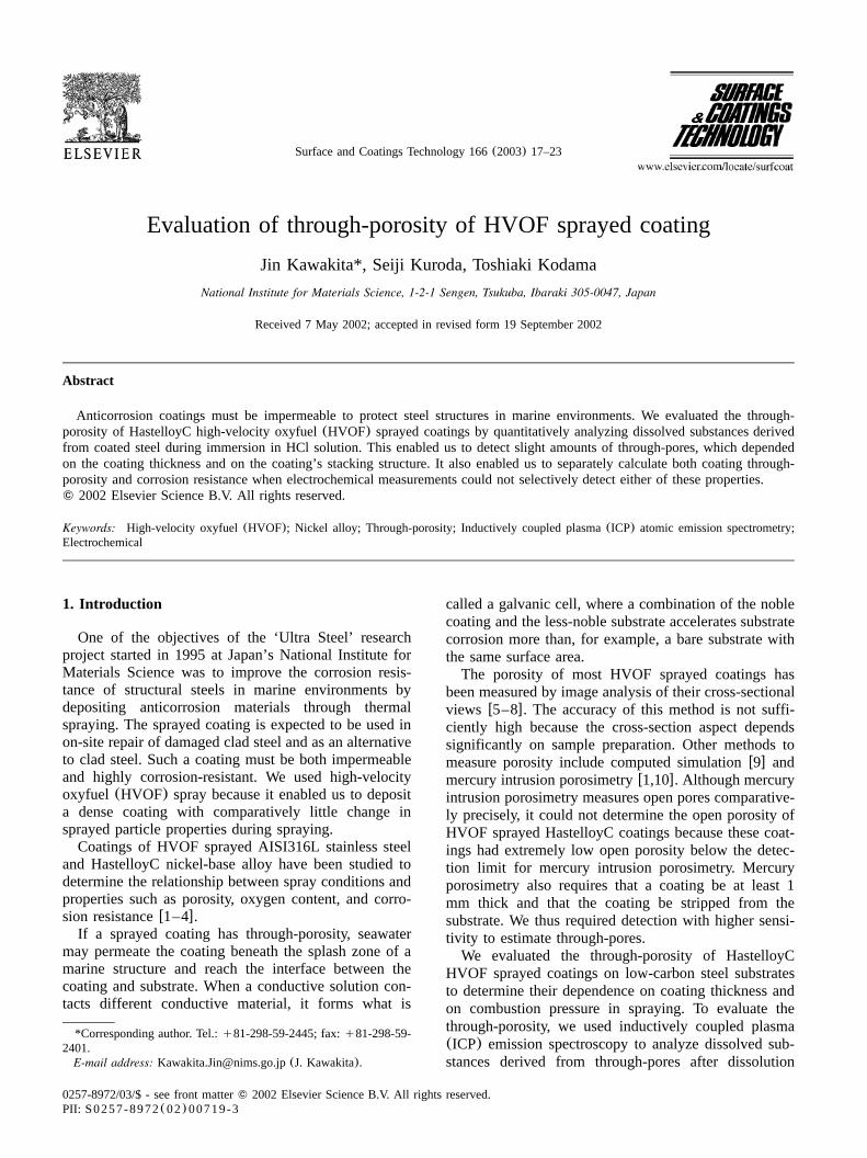
Fig. 9. Dependence of corrosion potential of specimen on coatingthickness in 0.5 M HCl:s, HastelloyC coating(SP) on SS400;n,HastelloyC coating(HP) on SS400;d, HastelloyC coating(SP) onHastelloyC276; andm, HastelloyC coating(HP) on HastelloyC276.Two dotted lines are bulk plates: --, HastelloyC276; and , SS400.«
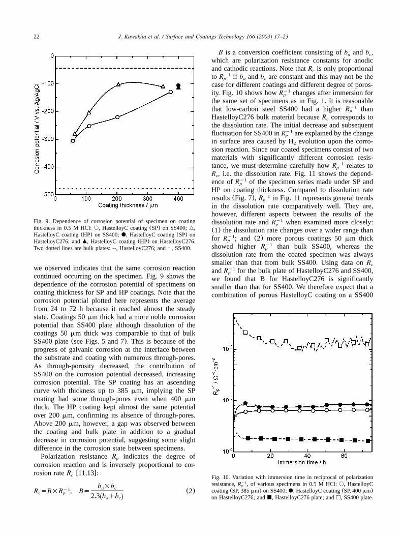
Fig. 10. Variation with immersion time in reciprocal of polarizationresistance,R , of various specimens in 0.5 M HCl:s, HastelloyCy1
p
coating(SP, 385mm) on SS400;d, HastelloyC coating(SP, 400mm)on HastelloyC276; andj, HastelloyC276 plate; andh, SS400 plate.
we observed indicates that the same corrosion reactioncontinued occurring on the specimen. Fig. 9 shows thedependence of the corrosion potential of specimens oncoating thickness for SP and HP coatings. Note that thecorrosion potential plotted here represents the averagefrom 24 to 72 h because it reached almost the steadystate. Coatings 50mm thick had a more noble corrosionpotential than SS400 plate although dissolution of thecoatings 50mm thick was comparable to that of bulkSS400 plate(see Figs. 5 and 7). This is because of theprogress of galvanic corrosion at the interface betweenthe substrate and coating with numerous through-pores.As through-porosity decreased, the contribution ofSS400 on the corrosion potential decreased, increasingcorrosion potential. The SP coating has an ascendingcurve with thickness up to 385mm, implying the SPcoating had some through-pores even when 400mmthick. The HP coating kept almost the same potentialover 200mm, confirming its absence of through-pores.Above 200mm, however, a gap was observed betweenthe coating and bulk plate in addition to a gradualdecrease in corrosion potential, suggesting some slightdifference in the corrosion state between specimens.Polarization resistanceR indicates the degree ofp
corrosion reaction and is inversely proportional to cor-rosion rateR w11,13x:c
b =ba cy1R sB=R , Bs (2)c p 2.3 b qbŽ .a c
B is a conversion coefficient consisting ofb andb ,a c
which are polarization resistance constants for anodicand cathodic reactions. Note thatR is only proportionalc
to R if b andb are constant and this may not be they1p a c
case for different coatings and different degree of poros-ity. Fig. 10 shows howR changes after immersion fory1
p
the same set of specimens as in Fig. 1. It is reasonablethat low-carbon steel SS400 had a higherR thany1
p
HastelloyC276 bulk material becauseR corresponds toc
the dissolution rate. The initial decrease and subsequentfluctuation for SS400 inR are explained by the changey1
p
in surface area caused by H evolution upon the corro-2
sion reaction. Since our coated specimens consist of twomaterials with significantly different corrosion resis-tance, we must determine carefully howR relates toy1
p
R , i.e. the dissolution rate. Fig. 11 shows the depend-c
ence ofR of the specimen series made under SP andy1p
HP on coating thickness. Compared to dissolution rateresults(Fig. 7), R in Fig. 11 represents general trendsy1
p
in the dissolution rate comparatively well. They are,however, different aspects between the results of thedissolution rate andR when examined more closely:y1
p
(1) the dissolution rate changes over a wider range thanfor R ; and (2) more porous coatings 50mm thicky1
p
showed higherR than bulk SS400, whereas they1p
dissolution rate from the coated specimen was alwayssmaller than that from bulk SS400. Using data onRc
andR for the bulk plate of HastelloyC276 and SS400,y1p
we found that B for HastelloyC276 is significantlysmaller than that for SS400. We therefore expect that acombination of porous HastelloyC coating on a SS400

23J. Kawakita et al. / Surface and Coatings Technology 166 (2003) 17–23
Fig. 11. Dependence of reciprocal of polarization resistance,R , ofy1p
specimen on coating thickness in 0.5 M HCl:s, HastelloyC coating(SP) on SS400; n, HastelloyC coating(HP) on SS400; d,HastelloyC coating(SP) on HastelloyC276; andm, HastelloyC coat-ing (HP) on HastelloyC276. Two dotted lines are bulk plates: --,HastelloyC276; and , SS400.«
substrate have lower B than bulk SS400 plate. ThisshiftsR upward for the same value ofR as indicatedy1
p c
by Eq. (2) and explains whyR for 50 mm specimensy1p
were somewhat above that for bulk steel plate. Theseresults indicate that althoughR may be used toy1
p
relatively compare the barrier capability of HVOF coat-ings, it remains difficult to calculate the dissolution ratefrom R .y1
p
4. Conclusions
The through-porosity of the HVOF sprayedHastelloyC coating(below 0.1 vol.% in open porosity)was chemically detected using ICP atomic emissionspectrometry of dissolved substances permeating viaconnecting pores in such coatings.
Through-porosity depended on coating thickness andon the sprayed-particle stacking structure. One coatingshowing zero through-porosity was prepared under ahigher combustion pressure than the standard and wasapproximately 400mm thick.This chemical detection method was also allowed to
determine the corrosion resistance of the coating itself,excluding the contribution of the substrate. This corro-sion resistance predominates the coated material ascoating density increases. Particularly for coatings with-out through-pores, it determines service life. Not allsprayed coatings had the same corrosion resistance astheir corresponding bulk material.Electrochemical parameters such as corrosion poten-
tial and polarization resistance could not be used toevaluate through-porosity selectively. They showed totalcoating performance, consisting of through-porosity andcoating corrosion resistance.
References
w1x S. Kuroda, T. Fukushima, M. Sasaki, T. Kodama, Proceedingsof the First International Thermal Spray Conference, Montreal,´Canada, May 2000, p. 455.
w2x T. Fukushima, S. Kuroda, Proceedings of the InternationalThermal Spray Conference, Singapore, May 2001, p. 527.
w3x J. Kawakita, T. Fukushima, S. Kuroda, T. Kodama, Proceedingsof the International Thermal Spray Conference, Singapore,May 2001, p. 1137.
w4x J. Kawakita, T. Fukushima, S. Kuroda, T. Kodama, Corros.Sci. 44(2002) 2561.
w5x W.C. Lih, S.H. Yang, C.Y. Su, S.C. Huang, I.C. Hsu, M.S.Leu, Surf. Coat. Technol. 54(2000) 133–134.
w6x G. Reisel, B. Wielage, S. Steinhauser, I. Morgenthal, R. Scholl,¨Surf. Coat. Technol. 19(2001) 146–147.
w7x A. Scrivani, S. Ianelli, A. Rossi, R. Groppetti, F. Casadei, G.Rizzi, Wear 250(2001) 107.
w8x M.K. Stanford, V.K. Jain, Wear 251(2001) 990–996.w9x A. Kulkarni, S. Sampath, A. Goland, H. Herman, B. Dowd,
Script. Mater. 43(2000) 417.w10x H.J. Kim, Y.G. Kweon, Thin Solid Films 342(1999) 201.w11x T. Tsuru, S. Haruyama, Boshoku Gijutsu 28(1979) 134.w12x J. Creus, H. Mazille, H. Idrissi, Surf. Coat. Technol. 130
(2000) 224.w13x M. Stern, A.L. Geary, J. Electrochem. Soc. 104(1957) 56.


![Properties of HVOF-sprayed Stellite-6 coatingsjultika.oulu.fi/files/nbnfi-fe2018080733445.pdf · In bulk form [2–8] or as cladded overlays, deposited by such techniques as metal](https://img.pdfslide.us/doc/110x75/5f534c880ff2fa124f365d56/properties-of-hvof-sprayed-stellite-6-in-bulk-form-2a8-or-as-cladded-overlays.jpg)