Embed Size (px)
Citation preview
Tampa Bay Estuary Program Technical Publication # 10-03
EVALUATION of ALTERNATIVE METHODS of ACHIEVING SEDIMENT QUALITY
TARGETS
FINAL REPORT
June 2003

EVALUATION OF ALTERNATIVE METHODS
OF ACHIEVING SEDIMENT QUALITY TARGETS
June 2003
Prepared for:
Tampa Bay Estuary Program 111 7th Avenue South
St. Petersburg, Florida 33701
Prepared by:
Janicki Environmental, Inc. 1155 Eden Isle Dr. N.E.
St. Petersburg, Florida 33704

Alternative Sediment Quality Methods Report June 2003
Page ii
EXECUTIVE SUMMARY The objective of this report falls under the broader goal of assisting in the development and implementation of the Tampa Bay sediment quality management strategy. The specific objective of this memorandum is to evaluate the alternative management options available to achieve sediment quality targets. Therefore, this document describes alternative management options to achieve sediment quality targets and estimates of costs associated with these methods. Contaminated sediment management options fall into two general categories, nonremoval and removal techniques. Nonremoval techniques involve the remediation of contaminated sediments in situ (i.e., in place). Removal techniques involve the remediation of contaminated sediments ex situ (i.e., out of place). Nonremoval techniques for contaminated sediments include natural recovery, sediment capping, in situ containment (hydraulic modification), and in situ treatment. Nonremoval techniques are single-component remedial alternatives. They do not require sediment removal, transport, or pretreatment. As a result, nonremoval techniques are often less complex and have lower costs than multicomponent alternatives (e.g., combinations of removal, transport, treatment, and disposal). In some cases (e.g., in situ treatment), nonremoval technologies may be similar to the treatment and disposal techniques used with dredged sediments (USEPA, 1994). Removal techniques for contaminated sediments include dredging and wet/dry excavation. Removal techniques are multi-staged remedial alternatives. They require sediment removal, transport, treatment, and disposal (USEPA, 1994).
Alternative Sediment Quality Methods Report June 2003
Page iii
FOREWORD This report was prepared by Janicki Environmental, Inc., under contract to the Tampa Bay Estuary Program.
Alternative Sediment Quality Methods Report June 2003
Page iv
ACKNOWLEDGEMENTS The major contributors to this document were Keith Hackett, Anthony Janicki, and Ray Pribble. The authors wish to acknowledge the following individuals who contributed to the steering and review of this project: Dick Eckenrod and Holly Greening.

Alternative Sediment Quality Methods Report June 2003
Page v
Table of Contents
EXECUTIVE SUMMARY ..................................................................................................... ii
FOREWORD ..................................................................................................................... iii
ACKNOWLEDGEMENTS .................................................................................................. iv
1.0 INTRODUCTION ....................................................................................................... 1
1.1 OBJECTIVE ................................................................................................................. 3
2.0 MANAGEMENT OPTIONS ......................................................................................... 3
2.1 NONREMOVAL TECHNIQUES......................................................................................... 3 2.1.1 Nonpoint Source Pollution Control ................................................................... 4 2.1.2 Natural Recovery .............................................................................................. 5 2.1.3 Sediment Capping............................................................................................. 5 2.1.4 In situ Containment........................................................................................... 7 2.1.5 In situ Treatment ............................................................................................... 8
2.2 REMOVAL TECHNIQUES..............................................................................................11 2.2.1 Dredging or wet excavation ............................................................................11 2.2.2 Dry Excavation................................................................................................13
3.0 ESTIMATING COSTS ................................................................................................13
3.1 PURPOSE OF COST ESTIMATES.....................................................................................14 3.2 ELEMENTS OF A COST ESTIMATE ..................................................................................15 3.3 DEVELOPMENT OF COST ESTIMATES .............................................................................17
3.3.1 Technology Screening.....................................................................................17 3.3.2 Preliminary Design..........................................................................................17 3.3.3 Implementation...............................................................................................18 3.3.4 Sources of Information ....................................................................................18
4.0 LITERATURE CITED ..................................................................................................20
Appendix A .....................................................................................................................A-1
Appendix B .....................................................................................................................B-1
Alternative Sediment Quality Methods Report June 2003
Page 1
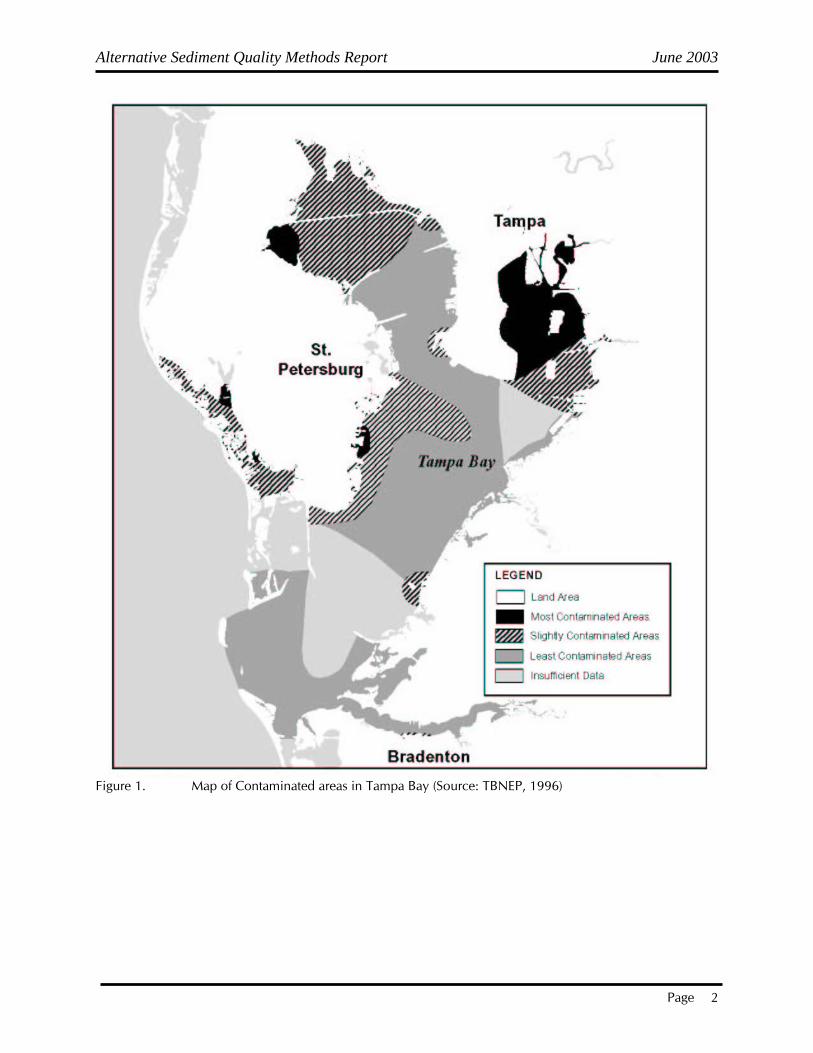
1.0 INTRODUCTION The major goal of the Tampa Bay Estuary Program (TBEP) is to develop and implement a comprehensive plan for the restoration and protection of Tampa Bay. Because of the need to address large-scale issues that impact the entire ecosystem, TBEP drafted a Comprehensive Conservation and Management Plan (CCMP) for the Tampa Bay Estuary and its surrounding watershed. Water and sediment quality was identified as one of the five most pressing problems facing Tampa Bay. The principle reason that sediment quality was identified as a pressing problem was because NOAA documented adverse biological effects in Tampa Bay sediments, oysters and fishes as part of its National Status and Trends Program (Long, 1994). Data from chemical and toxicological analyses of sediments, chemical analyses of oyster tissues, and chemical and biomarker analyses of resident fish showed strong agreement. The northern portion of Hillsborough Bay was the most contaminated region in Tampa Bay. Other small areas in western Old Tampa Bay, along the western shore of Middle Tampa Bay, and in lower Boca Ciega Bay also showed signs of degraded sediment quality. The chemical analyses indicated that many different substances occurred in sediments, probably acting together to induce toxicity and other biological effects. The identification of these contaminants in tissues of oysters and fish, observations of biochemical responses in fish, and the occurrence of toxicity in laboratory tests indicate that chemicals were bioavailable in the sediments. Observations of acute and sub-lethal toxicity in sediment toxicity tests and biomarker responses in fish, furthermore, indicate these chemicals may pose a toxicological risk to local biological resources (Long and Greening, 1999). Having identified areas in Tampa Bay that have contaminated sediments (Figure 1), the logical next step is to identify potential methods of remediation for these contaminated areas. However, a blanket approach to the problem is not advisable. Instead, an appropriate sediment management option should be selected on a case-by-case basis, after careful consideration of the risks posed by the contaminants, the benefits of the remediation, and the costs. Contaminated sediments may either be left in place or removed. Contaminated sediments should not be removed from a site if doing so would cause more harm than simply leaving them in place. If sediments are left in place, however, measures must be taken to limit the danger they pose to people and wildlife. Long-term biological and chemical monitoring should be established to measure any change in contaminant levels over time and the associated biological response (EPA contaminated sediments web page, http://www.epa.gov/waterscience/cs/aboutcs/ manage.html).
Alternative Sediment Quality Methods Report June 2003
Page 2
Figure 1. Map of Contaminated areas in Tampa Bay (Source: TBNEP, 1996)

Alternative Sediment Quality Methods Report June 2003
Page 3
1.1 Objective The objective of this report falls under the broader goal of assisting in the development and implementation of the Tampa Bay sediment quality management strategy. The specific objective of this memorandum is to evaluate the alternative management options available to achieve sediment quality targets. These options may include:
Nonremoval techniques • nonpoint source pollution control measures • natural recovery • sediment capping • in situ containment Removal techniques • dredging • dry excavation
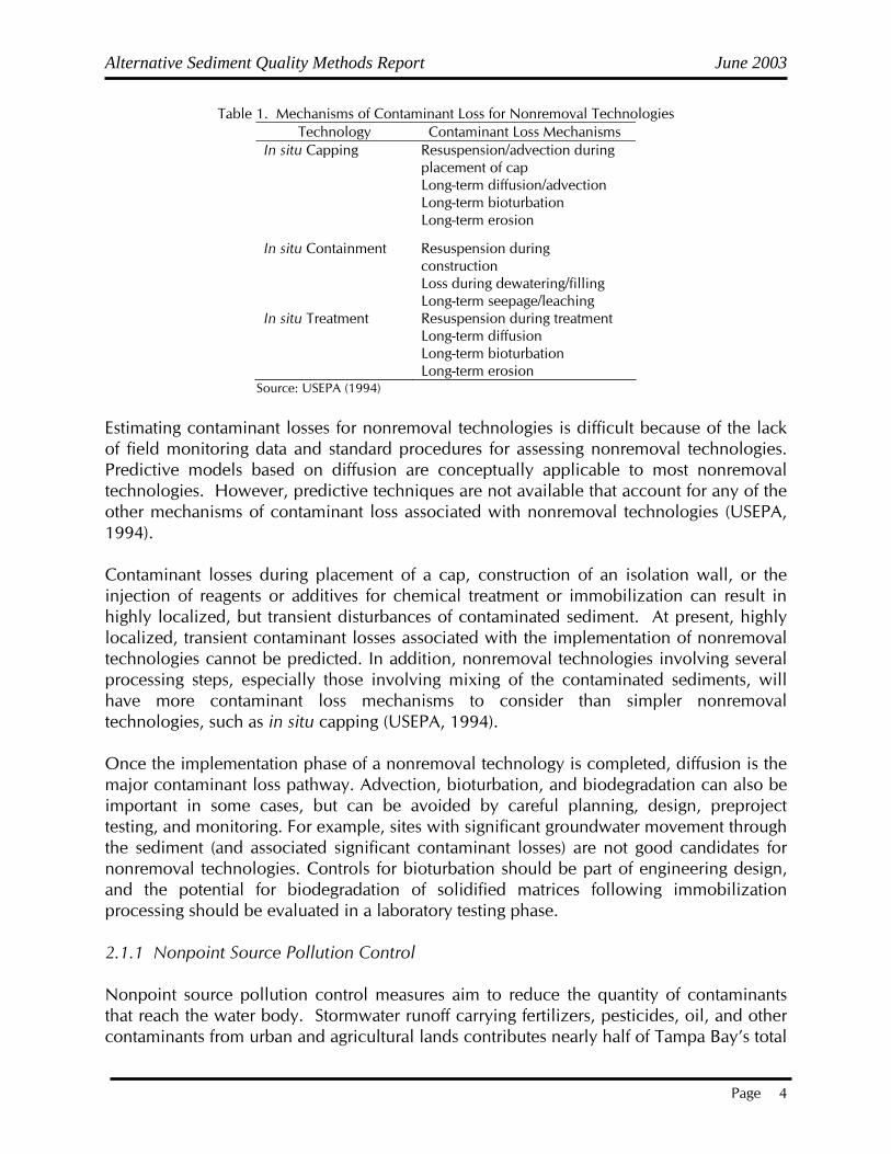
2.0 MANAGEMENT OPTIONS Contaminated sediment management options fall into two general categories, nonremoval and removal techniques. A summary of advantages and disadvantages associated with different management options can be found in Appendix A, Advantages and Disadvantages of Various Sediment Remedial Technologies (SMWG, http://www.smwg.org/products/ decisiontree/navframes/index.htm). Basic fact sheets developed for the different management options by the Sediment Management Working Group can be found in Appendix B. 2.1 Nonremoval Techniques Nonremoval techniques involve the remediation of contaminated sediments in situ (i.e., in place). Nonremoval techniques for contaminated sediments include natural recovery, sediment capping, in situ containment (hydraulic modification), and in situ treatment. Nonremoval techniques are single-component remedial alternatives. They do not require sediment removal, transport, or pretreatment. As a result, nonremoval techniques are often less complex and have lower costs than multicomponent alternatives (e.g., combinations of removal, transport, treatment, and disposal). In some cases (e.g., in situ treatment), nonremoval technologies may be similar to the treatment and disposal techniques used with dredged sediments (USEPA, 1994). The amounts of sediment contaminants lost during and after remediation need to be estimated to determine the benefits of remediation and to evaluate the impacts of remedial alternatives. The mechanisms for contaminant losses associated with nonremoval technologies are summarized in Table 1.
Alternative Sediment Quality Methods Report June 2003
Page 4
Table 1. Mechanisms of Contaminant Loss for Nonremoval Technologies Technology Contaminant Loss Mechanisms
In situ Capping Resuspension/advection during placement of cap Long-term diffusion/advection Long-term bioturbation Long-term erosion
In situ Containment Resuspension during construction Loss during dewatering/filling Long-term seepage/leaching
In situ Treatment Resuspension during treatment Long-term diffusion Long-term bioturbation Long-term erosion
Source: USEPA (1994)
Estimating contaminant losses for nonremoval technologies is difficult because of the lack of field monitoring data and standard procedures for assessing nonremoval technologies. Predictive models based on diffusion are conceptually applicable to most nonremoval technologies. However, predictive techniques are not available that account for any of the other mechanisms of contaminant loss associated with nonremoval technologies (USEPA, 1994). Contaminant losses during placement of a cap, construction of an isolation wall, or the injection of reagents or additives for chemical treatment or immobilization can result in highly localized, but transient disturbances of contaminated sediment. At present, highly localized, transient contaminant losses associated with the implementation of nonremoval technologies cannot be predicted. In addition, nonremoval technologies involving several processing steps, especially those involving mixing of the contaminated sediments, will have more contaminant loss mechanisms to consider than simpler nonremoval technologies, such as in situ capping (USEPA, 1994). Once the implementation phase of a nonremoval technology is completed, diffusion is the major contaminant loss pathway. Advection, bioturbation, and biodegradation can also be important in some cases, but can be avoided by careful planning, design, preproject testing, and monitoring. For example, sites with significant groundwater movement through the sediment (and associated significant contaminant losses) are not good candidates for nonremoval technologies. Controls for bioturbation should be part of engineering design, and the potential for biodegradation of solidified matrices following immobilization processing should be evaluated in a laboratory testing phase. 2.1.1 Nonpoint Source Pollution Control Nonpoint source pollution control measures aim to reduce the quantity of contaminants that reach the water body. Stormwater runoff carrying fertilizers, pesticides, oil, and other contaminants from urban and agricultural lands contributes nearly half of Tampa Bay’s total

Alternative Sediment Quality Methods Report June 2003
Page 5
annual nitrogen loading and more than 60 percent of the annual loadings of zinc, mercury, lead, and chromium (TBNEP, 1996). It is for this reason that The TBEP has already instituted several activities to address nonpoint source pollution due to stormwater runoff. 2.1.2 Natural Recovery When considering how to reduce risks that contaminated sediments pose to human health and the aquatic environment, it is important to recognize the capacity of natural processes to “heal” the impacted environment. This is referred to as natural attenuation. This approach to sediment remediation relies on the powerful natural processes that are inherent within all aquatic systems to reduce chemical of concern (COC) bioavailability and potential transport. The natural attenuation of aquatic systems is driven mostly by quantifiable physical mechanisms such as mixing and in-place burial of contaminated sediments. If the source of contamination is adequately addressed, the contaminated sediments will be buried by progressively cleaner sediments. This natural sedimentation process can reduce the physical availability of COCs for potential transport downstream and similarly reduce the bioavailability of COCs for potential exposure to human and ecological receptors. Other potentially significant mechanisms include chemical processes such as adsorption and redox reactions and biodegradation (Brown, 1999 http://www.smwg.org/products/decisiontree/navframes/index.htm). Despite today’s apparent emphasis on applying active remedial technologies in managing contaminated sediment, there is some evidence that natural attenuation can be applied as an effective remedial alternative or to enhance the protectiveness of other alternatives selected for aquatic sites. While the regulatory community and public tend to view the natural recovery of sediments as a no action alternative, the capacity for natural attenuation processes combined with performance monitoring may be a protective, feasible, and cost-effective alternative to be considered when evaluating potential remedies (Brown, 1999). 2.1.3 Sediment Capping In situ capping is the placement of a covering or cap over an in situ deposit of contaminated sediment (Figure 2). The cap may be constructed of clean sediments, sand, or gravel, or may involve a more complex design using geotextiles, liners, and multiple layers. In situ capping has been applied in riverine, nearshore, and estuarine environments. Conventional dredging and construction equipment and techniques can be used for in situ capping projects, but these practices must be precisely controlled. The success of projects to date and available monitoring data at several sites indicate that in situ capping may be an effective technique for long-term containment of contaminants (USEPA, 1994).

Alternative Sediment Quality Methods Report June 2003
Page 6
Figure 2. Typical sediment capping confiuguration (Source: USEPA, 1994) The construction of an in situ cap represents a deliberate modification to the morphology of the bottom of a waterway. Future uses of the waterway may be limited by this modification. A variation of in situ capping involves the removal of contaminated sediments to some depth, followed by capping the remaining sediments in place. This method is suitable when capping alone is not feasible because of hydraulic or navigation restrictions on the waterway depth. It may also be used where it is desirable to leave the deeper, more contaminated sediments capped in place. The primary technical considerations that affect the feasibility of in situ capping are the physical and hydraulic characteristics and the existing and future uses of the waterway. The suitability of in situ capping to a contaminated sediment site is less affected by the type or level of contaminants present, because it physically isolates the sediments and their associated contaminants. The ideal area for in situ capping would be sheltered and not exposed to high erosive forces, such as currents, waves, or navigation propeller wash, or to upwelling from groundwater (USEPA, 1994). Depending on the erosive forces present at a site, an in situ cap may have to be armored with stone or other material to keep the cap intact. Areas on five tributaries of the Great Lakes were examined under the ARCS Program in developing guidance on the hydraulic design of in situ caps (Maynord and Oswalt, 1993). River currents were the dominant erosive force in only one of five areas. The scour caused by navigation (recreational as well as commercial) was the dominant force in the other areas studied. The potential scour caused by large commercial vessels would necessitate very large armor stone, making in situ capping difficult in or near most active navigation channels (Environmental Laboratory 1987; Maynord and Oswalt 1993). Capital costs for in situ capping include costs of capping materials, construction equipment, and labor. These costs will be influenced by the complexity of the cap design,

Alternative Sediment Quality Methods Report June 2003
Page 7
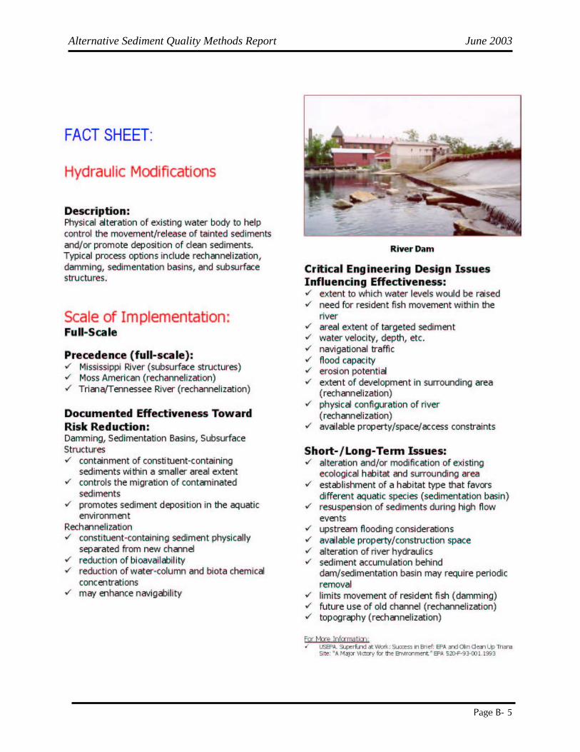
accessibility of the capping site, water depth, and other factors. If clean dredged material (e.g., from a navigation project) can be used in a capping application, capital costs could be greatly reduced. Operation and maintenance costs include monitoring and periodic cap replenishment. Based on the experience of the Corps' New England Division with dredged material capping, the costs for a routine long-term monitoring cycle (bathymetric surveys and camera profile) are about $30,000. This basic physical monitoring cycle is conducted every 2-3 years (USEPA, 1994). 2.1.4 In situ Containment In situ containment, also known as hydraulic modification, involves the complete isolation of a portion of the waterway. Physical barriers used to isolate a portion of a waterway include sheetpile, cofferdams, and stone or earthen dikes. Figure 3 shows a river dam that was used as a hydraulic modification. The isolated area can be used for the disposal of other contaminated sediments, treatment residues, or other fill material. The area may have to be modified (e.g., slurry walls, cap and cover) to prevent contaminant migration.
Figure 3. Example of in situ containment (Source: SMWG, 1999) The technical feasibility of using in situ containment is determined primarily by the physical conditions of the site. Areas that may be suitable for in situ containment include backwater areas, slips, turning basins, and some wide areas of rivers. Areas within active navigation channels are generally not suitable.

Alternative Sediment Quality Methods Report June 2003
Page 8
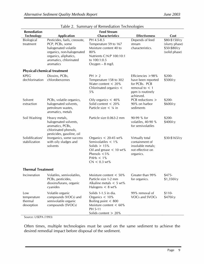
The primary factors limiting the feasibility of in situ containment are the potential impacts of the new fill on flow patterns, flooding, navigation, and habitat. Slips and turning basins are especially well suited, because they only need to be isolated at one end and can generally be filled without reducing the hydraulic capacity of the adjacent river channel. In situ containment will require structural measures and environmental controls to isolate the containment area from the adjacent waterway and prevent unacceptable contaminant migration. It may also be possible to completely reroute waterways with contaminated sediments. The waterway can then be dewatered, and the sediments removed, treated in place, or confined in place. This is an extreme measure and is only likely to be feasible for small waterways with limited flows. 2.1.5 In situ Treatment Some treatment technologies have been developed specifically for in situ application, while others have been adapted from ex situ treatment applications. Figure 4 shows equipment used to inject chemicals into sediments as a form of in situ treatment. Most in situ treatment technologies could also be applied to sediments that have been dredged and placed in a disposal area. A summary of remediation technologies is presented in Table 2.
Figure 4. Equipment used for in situ chemical treatment of sediments (Source: USEPA, 1994)
Alternative Sediment Quality Methods Report June 2003
Page 9
Table 2. Summary of Remediation Technologies Remediation Technology Application
Feed Stream Characteristics Effectiveness Cost
Biological treatment
Pesticides, fuels, creosote, PCP, PCBs, some halogenated volatile organics, non-halogenated organics, aliphatics, aromatics, chlorinated aromatics
PH 4.5-8.5 Temperature 59 to 167 Moisture content 40 to 80% Nutrients C:N:P 100:10:1 to 100:1:0.5 Oxygen – 8 mg/L
Depends of feed stream characteristics.
$80-$150/cy (slurry phase) $50-$80/cy (solid phase)
Physical/chemical treatment KPEG dechlorination
Dioxins, PCBs, chlorobenzenes
PH > 2 Temperature 158 to 302 Water content < 20% Chlorinated organics < 5%
Efficiencies >98% have been reported for PCBs. PCB removal to < 1 ppm is routinely achieved.
$200-$500/cy
Solvent extraction
PCBs, volatile organics, halogenated solvents, petroleum wastes, aromatics, metals
Oily organics < 40% Solid content < 20% Particle size < ¼ in
PCB reductions > 90% on harbor sediments
$200-$600/cy
Soil Washing Heavy metals, halogenated solvents, aromatics, PCBs, chlorinated phenols, pesticides, gasoline, oil
Particle size 0.063-2 mm 90-99 % for volatiles, 40-90 % for semivolatiles
$200-$400/cy
Solidification/ stabilization
Inorganics, some success with oily sludges and solvents
Organics < 20-45 wt% Semivolatiles < 1% Solids > 15% Oil and grease < 10 wt% Phenols <5% PAHs < 1% CN < 0.3 wt%
Virtually total containment of insoluble metals; not effective on organics.
$30-$165/cy
Thermal Treatment Incineration Volatiles, semivolatiles,
PCBs, pesticides, dioxins/furans, organic cyanides
Moisture content < 50% Particle size 1-2 mm Alkaline metals < 5 wt% Halogens < 8 wt%
Greater than 99% for organics.
$475-$1,350/cy
Low temperature thermal desorption
Volatile organic compounds (VOCs) and semivolatile organic compounds (SVOCs)
Solids 1-1.5 in dia. Organics < 10% Boiling point < 800 Moisture content < 60% PH 5-11 Solids content > 20%
99% removal of VOCs and SVOCs
$110-$470/cy
Source: USEPA (1993) Often times, multiple technologies must be used on the same sediment to achieve the desired remedial impact before disposal of the sediment.
Alternative Sediment Quality Methods Report June 2003
Page 10
In situ treatment has several limitations. One such limitation is the lack of process control. Process control is contingent upon effectively monitoring conditions at the site, typically by performing sampling and analysis at appropriate frequencies, before and after treatment. The efficacy of in situ treatment of sediments is difficult to determine because of the nonhomogeneous distribution of contaminants, sediment physical properties, and treatment chemicals. One of the limitations of in situ treatment is the difficulty in ensuring uniform dosages of chemical reagents or additives throughout the sediments to be treated. Areas of sediment within the site may receive varying levels of treatment, with some areas of sediment being untreated while others are overtreated relative to the intended treatment goal. In situ treatment may be less cost effective than ex situ treatment when these factors are considered (USEPA, 1994). Among the most significant limitations to in situ treatment is the impact of the process on the water column. Processes that would release contaminants, reagents, or heat, or produce other negative impacts on the overlying water column, are not likely to be acceptable for in situ sediment remediation. A suitable in situ treatment technology is, in most cases, one that can be applied with minimal disturbance of the sediment-water interface or one in which the process is physically isolated from the water column. There are two general methods of applying in situ treatment that address this limitation: surface application and isolation of the sediments prior to treatment. Several types of treatment processes might be used within these applications. Surface application is the introduction of one or more material(s) (e.g., reagents, additives, nutrients) onto the sediments by spreading and settling, or injecting them into the sediments through tubes, pipes, or other devices. Researchers at the Canadian National Water Research Institute have developed and demonstrated equipment that is capable of injecting solutions of oxidizing chemicals into uncompacted sediments at a controlled rate (Murphy et al., 1993). The second method for applying sediment treatment in place is by isolating the sediment from the surrounding environment. This method allows the use of reagents or process conditions that might otherwise cause deleterious effects to the waterway. Various types of equipment might be used for isolating the sediments, including a caisson, sheetpile cell, tube, or box. Within the enclosing caisson, the water may be removed or left behind. After the treatment is completed, the caisson can be removed and reset at an adjacent area. Capital costs for in situ treatment include the costs of equipment, materials, reagents, and labor necessary to treat the sediments. The development and fabrication costs for the application equipment may be significant. A substantial amount of development cost may also be required for the treatment process itself, if it has not been applied in situ (USEPA, 1994).
Alternative Sediment Quality Methods Report June 2003
Page 11
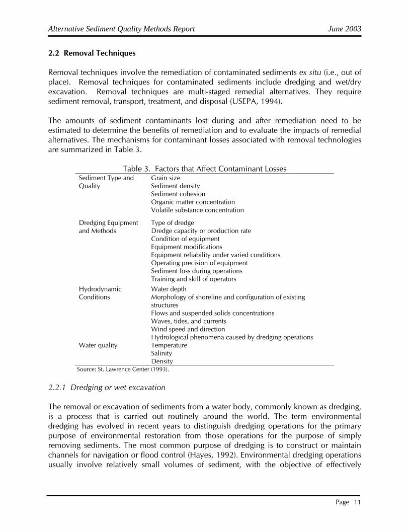
2.2 Removal Techniques Removal techniques involve the remediation of contaminated sediments ex situ (i.e., out of place). Removal techniques for contaminated sediments include dredging and wet/dry excavation. Removal techniques are multi-staged remedial alternatives. They require sediment removal, transport, treatment, and disposal (USEPA, 1994). The amounts of sediment contaminants lost during and after remediation need to be estimated to determine the benefits of remediation and to evaluate the impacts of remedial alternatives. The mechanisms for contaminant losses associated with removal technologies are summarized in Table 3.
Table 3. Factors that Affect Contaminant Losses
Sediment Type and Quality
Grain size Sediment density Sediment cohesion Organic matter concentration Volatile substance concentration
Dredging Equipment and Methods
Type of dredge Dredge capacity or production rate Condition of equipment Equipment modifications Equipment reliability under varied conditions Operating precision of equipment Sediment loss during operations Training and skill of operators
Hydrodynamic Conditions
Water depth Morphology of shoreline and configuration of existing structures Flows and suspended solids concentrations Waves, tides, and currents Wind speed and direction Hydrological phenomena caused by dredging operations
Water quality Temperature Salinity Density
Source: St. Lawrence Center (1993).
2.2.1 Dredging or wet excavation The removal or excavation of sediments from a water body, commonly known as dredging, is a process that is carried out routinely around the world. The term environmental dredging has evolved in recent years to distinguish dredging operations for the primary purpose of environmental restoration from those operations for the purpose of simply removing sediments. The most common purpose of dredging is to construct or maintain channels for navigation or flood control (Hayes, 1992). Environmental dredging operations usually involve relatively small volumes of sediment, with the objective of effectively
Alternative Sediment Quality Methods Report June 2003
Page 12
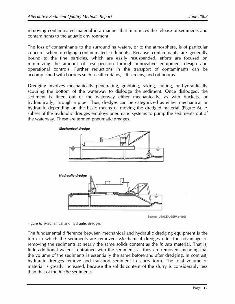
removing contaminated material in a manner that minimizes the release of sediments and contaminants to the aquatic environment. The loss of contaminants to the surrounding waters, or to the atmosphere, is of particular concern when dredging contaminated sediments. Because contaminants are generally bound to the fine particles, which are easily resuspended, efforts are focused on minimizing the amount of resuspension through innovative equipment design and operational controls. Further reductions in the transport of contaminants can be accomplished with barriers such as silt curtains, silt screens, and oil booms. Dredging involves mechanically penetrating, grabbing, raking, cutting, or hydraulically scouring the bottom of the waterway to dislodge the sediment. Once dislodged, the sediment is lifted out of the waterway either mechanically, as with buckets, or hydraulically, through a pipe. Thus, dredges can be categorized as either mechanical or hydraulic depending on the basic means of moving the dredged material (Figure 6). A subset of the hydraulic dredges employs pneumatic systems to pump the sediments out of the waterway. These are termed pneumatic dredges.
Figure 6. Mechanical and hydraulic dredges The fundamental difference between mechanical and hydraulic dredging equipment is the form in which the sediments are removed. Mechanical dredges offer the advantage of removing the sediments at nearly the same solids content as the in situ material. That is, little additional water is entrained with the sediments as they are removed, meaning that the volume of the sediments is essentially the same before and after dredging. In contrast, hydraulic dredges remove and transport sediment in slurry form. The total volume of material is greatly increased, because the solids content of the slurry is considerably less than that of the in situ sediments.
Alternative Sediment Quality Methods Report June 2003
Page 13
A review of 44 remediation projects by Cushing (1999) revealed the overall costs for the dredging projects ranged from $44 to $1,842 per cy, with a median of about $200 to $275 per cy. The high overall cost is due to two primary factors: low production rates and high costs for disposal. 2.2.2 Dry Excavation Dry excavation involves the following activities:
• Diverting water away from the targeted sediment area by means of rechanneling, bypass pumping, siphoning, or isolation with barriers
• Pumping the standing water out of the isolated target area • Maintaining conditions as dry as practical in the target area by continually pumping
out in-seepage and groundwater • Removing the dry sediments with conventional excavating equipment.
The dry removed sediments may still require either additional land-based dewatering or stabilization/solidification, to be followed by landfilling or treatment and reuse. Dry excavation, by its nature, is typically limited to relatively small shallow target areas in streams or shallow lake, pond, or marsh areas of manageable size. Otherwise, the water diversion/removal logistics become prohibitive. Cushing (1999) found that the overall costs for the dry/wet removal projects ranged from $21 to $1,500 per cy, with a median of about $450 per cy. The high overall cost is due to the following three primary factors:
• Lower production rates than for traditional earth moving projects due to difficulties with accessibility and wet terrain
• Additional water control and handling requirements imposed for maintaining the dry condition
• High costs for disposal
3.0 ESTIMATING COSTS This section discusses the development of cost estimates for sediment remedial alternatives to support the decision-making and implementation processes. There is no existing guidance on estimating costs specifically for sediment remediation projects; however, there is considerable guidance on estimating costs for general construction and some guidance for hazardous waste remediation projects. This discussion presents the cost estimating procedures used by the Corps for civil works projects and those used by the USEPA for Superfund projects. The appropriate guidance for most sediment remediation projects would include a combination of these approaches.
Alternative Sediment Quality Methods Report June 2003
Page 14
3.1 Purpose of Cost Estimates Project cost estimates are required during all phases of a sediment remediation project, from initial planning, through detailed design, and during construction and operation. The purpose of the cost estimates will change as the project progresses. During the planning stages, cost estimates are used as a criterion for screening technologies and selecting the preferred alternative. At the detailed design stage, cost estimates are often used to compare technically equivalent features and identify those that may be suitable for value engineering studies. Following detailed design and preparation of plans and specifications, cost estimates are used to evaluate bids on project construction and operation. During construction, cost estimates are used for scheduling payments, contract negotiation, and dispute resolution. The reliability of a cost estimate depends largely on the level of detail available at the time it is prepared. It also depends on the predictability of variables and factors used to develop the cost estimate. A thorough knowledge and understanding of the scope of work and all components associated with site remediation is necessary for the development of a reliable cost estimate, including a clear understanding of the construction operations and techniques that would be used. Cost estimates should complement the decision path. For civil works projects, such as maintenance dredging, there are two types of cost estimates in the decision-making process: the current working estimate and the government estimate. The current working estimate is an estimate that is prepared and updated periodically during the planning and design of a project. The level of detail and reliability of this estimate reflect the current state of project evaluation and design (USACE, 1980). The current working estimate is a total project cost estimate, which includes all reasonable costs that will be required during project implementation (i.e., the estimated costs of construction and operation contracts, engineering and design efforts, construction management and real estate easements, and land acquisition). The current working estimate is used as a tool to support the decision-making process and control costs, and should be prepared with as much accuracy as possible, so that the total project cost estimate for site remediation can be relied upon at the earliest possible stage in the decision-making process. For virtually all projects that are funded by the Federal government, and for most projects funded by other governmental agencies, a government estimate or equivalent is developed at the end of detailed design and immediately prior to the advertisement of the contract(s) for construction and operation (USACE, 1982). The government estimate is used to evaluate construction contract bids, control negotiations, establish a pricing objective for procurement and contracting purposes, and serve as a guide in developing progress payment schedules. It is a detailed construction cost estimate and does not include the other noncontract items of the current working estimate. The development of a government estimate for a Federal project must follow the procedures and guidelines of the Federal Acquisition Regulation (FAR) (48 CFR Chapters 1-99).
Alternative Sediment Quality Methods Report June 2003
Page 15
3.2 Elements of a Cost Estimate A sediment remediation project has capital, operation, and maintenance costs. Capital costs include expenditures that are initially incurred to develop and implement a remedial action (e.g., dredging and transportation, construction and operation of a treatment system, construction of a disposal facility) and major capital expenditures anticipated in future years (e.g., capping a confined disposal facility [CDF] or decontamination of treatment equipment) (Burgher et al., 1987). The following elements should be considered in developing estimates of capital costs (Cullinane et al., 1986; Burgher et al., 1987):
• Relocation costs • Costs of lands, easements, and rights-of-way • Land and site development costs • Costs for buildings and services • Equipment costs • Replacement costs • Disposal costs • Engineering expenses • Construction expenses • Legal fees, licenses, and permits • Contingency allowances • Startup and shakedown costs • Costs of health and safety requirements during construction
Operation and maintenance are post-construction activities needed to ensure the effectiveness of a remedial action (Burgher et al., 1987). These activities might include treatment plant operations, surface water and leachate management at a disposal facility, and monitoring and routine maintenance at disposal sites. The following elements should be considered in developing estimates of operation and maintenance costs (Cullinane et al., 1986a; Burgher et al., 1987):
• Operating labor costs • Maintenance materials and labor costs • Costs of auxiliary materials and energy • Purchased service costs • Administrative costs • Insurance, taxes, and licensing costs • Maintenance reserve and contingency fund
The capital, operation, and maintenance cost data needed for preparing estimates are divided into two categories, direct costs and indirect costs. The direct costs are those that are directly attributable to a unit of work. They are generally referred to as labor, equipment, and material/supply costs. The labor rate, equipment rate, and material/supply quotes are readily available from many sources. However, production rates, hours of work,

Alternative Sediment Quality Methods Report June 2003
Page 16
size of crew, selection of equipment and treatment plants, and schedules are estimated largely from site-specific data. There are some differences between the civil works and Superfund guidance for estimating indirect costs. The Corps approach considers indirect costs, sometimes referred to as distributed costs, to include all costs that are not directly attributable to a unit of work, but are required for the project. These costs might include field office and home office operations, permits, and insurance. The USEPA guidance for hazardous waste remediation (Burgher et al., 1987) includes these costs, plus engineering expenses, startup/shakedown costs, and contingency allowances, as indirect costs. Indirect costs are typically estimated as a fixed percentage of the total direct costs. For preliminary cost estimates, indirect costs (as defined by the Corps) may be estimated as 10-15 percent of direct costs. The USEPA guidance (Burgher et al., 1987) offers the following numbers for estimating specific indirect costs:
• Engineering expenses (7-15 percent of direct capital costs) • Legal fees, licenses, and permits (1-5 percent of total project costs) • Startup and shakedown costs (5-20 percent of capital costs) • Contingency allowances (15-25 percent of total capital costs)
When screening-level construction cost estimates are prepared, there are generally few details available that would warrant a detailed analysis of direct and indirect costs; total unit price data are often used instead. However, when a detailed construction cost estimate is required in the later stages of design and implementation, direct and indirect cost data are estimated separately. The level of confidence of a cost estimate depends on the level of detail available at the time it is prepared. One method to improve the confidence in the cost estimate is to assess and include appropriate contingencies in the estimate. A contingency is a form of allowance to cover unknowns, uncertainties, and/or unanticipated conditions that are not possible to adequately evaluate from the available data. A guideline for contingency rates is shown in Table 4.
Table 4. Contingency Rates for Cost Estimates Construction Cost Range
Project Stage <$500K $500K-$1M $1M-$5M >$5M Feasibility Screening level Preliminary design
30% 25%
25% 20%
25% 20%
25% 20%
Implementation Detailed design Plans and specifications Contract award
20% 15% 5%
15% 10% 5%
15% 10% 5%
15% 10% 5%
Source: Adapted from USACE (1992).

Alternative Sediment Quality Methods Report June 2003
Page 17
These rates are empirical and are only a guide. USEPA contingency allowances for feasibility studies (between 15 and 25 percent of capital costs) are in general agreement with the numbers shown in Table 5. 3.3 Development of Cost Estimates 3.3.1 Technology Screening At the screening level, the project cost analysis is very crude and limited to available information on the sediments, site conditions, and technologies being considered. Because the level of detail is minimal at this phase, historical data and parameters of similar past projects are recommended for the development of the cost estimate. The USEPA has developed a Remedial Action Cost Compendium (Yang et al., 1987) that shows the range of actual costs at Superfund projects. Historical cost data on the pretreatment and treatment components are very limited, and in some cases the only data available are projections made by technology vendors based on bench- or pilot-scale applications. Cost projections for technologies that do not already have full-scale equipment with some operating history should be approached with a certain amount of skepticism. One of the major factors in the cost of many innovative treatment technologies is the investment required for the development, scaleup, construction, and testing of full-scale equipment. The amortization of these development costs greatly affects their unit costs and the degree of uncertainty associated with those costs. Very few remediation projects are able to bear these development costs alone, and few companies are willing to make this investment unless there is a clear indication that there will be a dependable market for the technology at several remediation sites. One potential solution to this handicap is for interests from several Areas of Concern having similar sediment contamination problems to join forces in financing the development or acquisition of a remediation technology. 3.3.2 Preliminary Design During the preliminary design phase, a limited number of remedial alternatives are evaluated in sufficient detail to make a selection for implementation. This phase is comparable to the feasibility study for Superfund projects. The preliminary design should contain sufficient engineering and design information that could readily lead into the next phase (the detailed design). The cost estimate should be prepared based on the latest information available and should include all reasonable costs required in the implementation phase. The estimate should incorporate costs for additional engineering and design, real estate easements and land acquisition, and construction costs. This cost estimate will serve as a baseline current working estimate for project management through the implementation phase.

Alternative Sediment Quality Methods Report June 2003
Page 18
The process for evaluating costs during a Superfund feasibility study includes the following steps (Burgher et al., 1987):
• Estimation of costs • Present worth analysis • Sensitivity analysis • Input to alternatives analysis
The accuracy of cost estimates for feasibility studies for Superfund projects should be within the range of +50 to -30 percent (Burgher et al., 1987). 3.3.3 Implementation This phase should include preparation of a detailed design and the plans and specifications for contracting the construction and operation of the remedial alternative. During the detailed design, cost estimates can be used to compare technically equivalent features in a process known as VE. VE is directed at analyzing the function of construction, equipment, and supplies for the purpose of achieving these functions at reduced life-cycle cost without sacrificing quality, aesthetics, or operations and maintenance capability (USACE 1987). During the development of plans and specifications, a detailed government estimate is prepared. This government estimate is used to evaluate bids on project construction and operation contracts. Bids are evaluated for balance as well as dollar amount. Corps regulations for civil works projects will not allow a contract award if the low bid exceeds the government estimate by more than 25 percent. During construction, cost estimates are used for scheduling payments, contract negotiations, and dispute resolution. 3.3.4 Sources of Information The accuracy of a cost estimate depends on the reliability of the information used in its development. For some of the components of a sediment remedial alternative there are a large number of sources of cost data available. A list of a few sources that could be consulted for cost estimates is shown in Table 5.

Alternative Sediment Quality Methods Report June 2003
Page 19
Table 5. Sources of Information for Cost Data Source Type of Information
R. S. Means Cost Data Unit costs for various construction activities
Dodge Guide Unit costs for various construction activities
Corps Unit Price Books Unit costs for various construction activities
Marshall Stevens Index Treatment plant and equipment costs and cost index
Chemical Engineering Treatment plant and equipment costs
Engineering News Record Construction cost index for updating construction capital costs
Civil Works Construction Cost Index System
Regional adjustment factors for construction costs
U. S. Department of Energy Energy costs, including regional differences
U. S. Department of Labor Labor costs, including regional differences
Federal Emergency Management Administration
Relocation costs
Source: USEPA (1994).
Construction costs may vary significantly from one region of the country to another. To convert approximate costs, area adjustment factors may be applied. Some Federal agencies, such as the U.S. Departments of Labor and Energy, maintain regional cost information. The Corps maintains a Civil Works Construction Cost Index System (CWCCIS), which may be used as a guide for regional construction cost adjustments.

Alternative Sediment Quality Methods Report June 2003
Page 20
4.0 LITERATURE CITED Brown, M.P. 1999. The Role Of Natural Attenuation/Recovery Processes In Managing Contaminated Sediments. Bouck and Lee. Sediment Management Working Group. http://www.smwg.org/products/decisiontree/navframes/index.htm Burgher, B., M. Culpepper, and W. Zieger. 1987. Remedial action costing procedures manual. EPA/600/8-87/049. Prepared for U.S. Environmental Protection Agency, Office of Solid Waste and Emergency Response and Hazardous Waste Engineering Research Laboratory, Washington, DC. Cullinane, M.J., D.E. Averett, R.A. Shafer, J.W. Male, C.L. Truitt, and M.R. Bradbury. 1986a. Guidelines for selecting control and treatment options for contaminated dredged material requiring restrictions. Puget Sound Dredged Disposal Analysis, U.S. Army Corps of Engineers, Seattle District, Seattle, WA. Cushing, B. S. 1999. State of Current Contaminated Sediment Management Practice. Applied Environmental Management, Inc. Sediment Management Working Group. http://www.smwg.org/products/decisiontree/navframes/index.htm Environmental Laboratory. 1987. Disposal alternatives for PCB-contaminated sediments from Indiana Harbor, Indiana. Miscellaneous Paper EL-87-9. U.S. Army Engineer Waterways Experiment Station, Vicksburg, MS. Hayes, D.F. 1992. Anticipating sediment resuspension and contaminant release during environmental dredging operations. In: Proc. of the International Symposium on Environmental Dredging, September 30-October 2, 1992, Buffalo, NY. Long, E. R., D. A. Wolfe, R. S. Carr, K. J. Scott, G. B. Thursby, H. L. Windom, R. Lee, F. D. Calder, G. M. Sloane, and T. Seal. 1994. Magnitude and extent of sediment toxicity in Tampa Bay, Florida. NOAA Technical Memorandum NOS ORCA 78. National Oceanic and Atmospheric Administration. Silver Springs, MD. Long, E. R. and H. S. Greening. 1999. Chemical contamination in Tampa Bay: Extent, toxicity, potential sources and possible sediment quality management plans. National Oceanic and Atmospheric Administration. Silver Springs, MD. Maynord, S., and R. Oswalt. 1993. In-situ capping/armoring. U.S. Army Engineer Waterways Experiment Station, Vicksburg, MS. Murphy, T., H. Brouwer, A. Moller, M. Fox, D. Jeffries, J. Thachuk, H. Savile, and H. Don. 1993. Preliminary analysis of in situ bioremediation in Hamilton Harbour. In: Proc. of Workshop on the Removal and Treatment of Contaminated Sediments. Environment Canada, Toronto, Ontario.
Alternative Sediment Quality Methods Report June 2003
Page 21
St. Lawrence Centre. 1993. Selecting and operating dredging equipment: a guide to sound environmental practices. Prepared in collaboration with Public Works Canada and the Ministere de l'Environnement du Quebec, and written by Les Consultants Jacques Berube Inc. Cat No. En 40-438/1993E. Tampa Bay National Estuary Program. 1996. Charting the Course: The Comprehensive Conservation and Management Plan for Tampa Bay. USACE. 1980. Guidelines for designing, operating, and managing dredged material containment areas. Engineer Manual EM 1110-2-5006. U.S. Army Corps of Engineers, Office of the Chief of Engineers, Washington, DC. USACE. 1982. Cost estimates-government estimate of fair and reasonable cost to contractor. Engineer Manual EM 1110-2-1302. U.S. Army Corps of Engineers, Washington, DC. USACE. 1987. Value engineering officer's operational guide. Engineer Pamphlet EP 11-1-3. U.S. Army Corps of Engineers, Office of the Chief of Engineers, Washington, DC. USACE. 1992. Civil works cost engineering. Engineer Regulation ER 1110-8-1. U.S. Army Corps of Engineers, Office of the Chief of Engineers, Washington, DC. USEPA. 1993. Selecting Remediation Techniques for Contaminated Sediment. EPA 823-B93-001. Office of Water, Washington, DC and Office of Research and Development, Cincinnati, Ohio. USEPA. 1994. Assessment and Remediation of Contaminated Sediments (ARCS) Remediation Guidance Document. EPA 905-B94-003. Chicago, IL. Great Lakes National Program Office. (http://www.epa.gov/glnpo/arcs/EPA-905-B94-003/EPA-905-B94-003.html) USEPA. 1985. Handbook: estimating sludge management costs. U.S. Environmental Protection Agency, Office of Research and Development. Published by Technomic Publishing Comp., Inc., Lancaster, PA. Yang, E.C., D. Bauma, L. Schwartz, and J.D. Werner. 1987. A compendium of technologies used in the treatment of hazardous wastes. EPA/625/8-87/014. U.S. Environmental Protection Agency, Center for Environmental Research Information, Cincinnati, OH.

Alternative Sediment Quality Methods Report June 2003
Page A- 1
Appendix A Advantages and Disadvantages of Various Sediment Remedial Technologies

Alternative Sediment Quality Methods Report June 2003
Page A- 2

Alternative Sediment Quality Methods Report June 2003
Page A- 3

Alternative Sediment Quality Methods Report June 2003
Page A- 4

Alternative Sediment Quality Methods Report June 2003
Page A- 5
Alternative Sediment Quality Methods Report June 2003
Page B- 1
Appendix B Sediment Management Options Fact Sheets
Alternative Sediment Quality Methods Report June 2003
Page B- 2
Alternative Sediment Quality Methods Report June 2003
Page B- 3
Alternative Sediment Quality Methods Report June 2003
Page B- 4
Alternative Sediment Quality Methods Report June 2003
Page B- 5
Alternative Sediment Quality Methods Report June 2003
Page B- 6