Embed Size (px)
Citation preview

03/2021
Evaluation ElectronicsFor Metrology Applications

2
For many metrology applications, ranging from simple measuring stations to complex inspection systems with multiple measuring points, HEIDENHAIN supports you with compatible evaluation electronics.
Their functionality is always oriented toward the specific application. Whether for an SPC inspection station, profile projector, or measuring microscope, the HEIDENHAIN evaluation electronics for metrology applications are the right choice for your measurement tasks.
Digital readouts from HEIDENHAIN for manually operated machine tools optimally support the operator with practical cycles for milling, drilling, and turning. You can find these digital readouts on the Internet at www.heidenhain.de or in the Digital Readouts and Linear Encoders for Manually Operated Machine Tools brochure.
Contents
Overview
Selection guide for measurement and inspection tasks 4
Specifications
Measurement and inspection tasks ND 280: evaluation unit for simple measuring and positioning tasks 6
ND 287: evaluation unit for measuring and inspection stations 8
GAGE-CHEK 2000: evaluation unit for demanding measured-value acquisition 10
EIB 700: signal converter for computer-aided measured-value acquisition 14
IK 220: signal converter for computer-aided measured-value acquisition 16
Mounting
Dimensions and installation ND 200 18
EIB 700 19
GAGE-CHEK 2000 20
Accessory: adapter connectors 22
Accessory: external operating element 22
Electrical connection
Interfaces Overview 23
Optional assemblies for the ND 287 24
Switching inputs/outputs on the ND 287 25
EIB 700 and IK 220 evaluation electronics 27
Encoder inputs 28
EIB application software for the EIB 700 31
Evaluation electronics for measurement and inspection tasks
Further information:
Comprehensive descriptions of all available interfaces as well as general electrical information are included in the Interfaces of HEIDENHAIN Encoders brochure (ID 1078628-xx).
For the required cables, please refer to the Cables and Connectors brochure (ID 1206103-xx).
You can download the operating instructions in the desired language free of charge from the HEIDENHAIN homepage.
This brochure supersedes all previous editions, which thereby become invalid.The basis for ordering from HEIDENHAIN is always the brochure edition valid when the order is placed.
Standards (ISO, EN, etc.) apply only where explicitly stated in the brochure.

ND 287
GAGE-CHEK 2000
IK 220
EIB 700
54
Selection guideMeasurement and inspection tasks
Screen Axes Functions Options/Additional functions Model Page
Length Angle
ND 200Evaluation unit for• Measurement equipment• Adjustment and inspection equipment• SPC inspection stations• Simple infeed and positioning tasks
Monochrome 1 (adjustable) – – ND 280 6
Color Up to 2 (adjustable)
Metrological and statistical functions (sorting and tolerance checking, measurement series, SPC)
Second encoder for sum/difference display, temperature compensation
ND 287 8
GAGE-CHEK 2000Evaluation unit for• Positioning equipment• Measuring fixtures• Adjustment and inspection equipment
Color touchscreen
Up to 3 (adjustable)
• Acquisition of precise measured values, and spot-on positioning in metrology applications
• 100 presets• Dial gage: comparison of the displayed value with
nominal value, warning threshold, and tolerance threshold
• Measurement series with minimum and maximum value recording
• Difference of minimum and maximum values (range)• Measurement of master parts (mastering)• Data transfer either manually, continuously, or triggered
by touch probe or switching function• Diameter/radius display• Relative measurement• Probing functions: edge, centerline, and circle• User administration• Configurability of each axis for length or angle display• Coupled axis for sum measurement or differential
measurement
– GC 2013 10GC 2023
GC 2093
EIB 700Signal converter for computer-aided measured-value acquisition on• Measuring machines• Inspection stations• Multi-gauging fixtures• Mobile data acquisition
PC screen 4 (adjustable) • Precise position measurement; updating rate of up to 50 kHz
• Programmable measured-value inputs• Internal and external measured-value triggers • Measured-value memory for typically 250 000 measured
values per channel• Standard Ethernet interface connection to higher-level
computer systems
Mounting bracket for 19-inch systems EIB 741EIB 742
14
IK 220Signal converter as a PCI slot card for computer-aided measured-value acquisition on measuring and inspection stations
PC screen 2 (adjustable) • Programmable measured-value inputs• Internal and external measured-value triggers• Measured-value memory for 8192 measured values
per channel
Assemblies for encoder outputs and external inputs/outputs
IK 220 16

76
The ND 280 evaluation unit for one axis is suitable for measuring and inspection stations, as well as simple positioning tasks. The universal encoder input permits the connection of all incremental encoders with 11 µAPP and 1 VPP signals, and absolute encoders with the EnDat 2.2 interface from HEIDENHAIN.
DesignThe ND 200 series features a sturdy aluminum die-cast housing. Its splash-proof, full-travel keyboard is built to handle shopfloor conditions. For displaying the measured values, a graphics-capable screen shows the status display and soft keys.
ND 280Evaluation unit for simple measuring and positioning tasks
ND 280
Axes One
Encoder inputs » 1 VPP, » 11 µAPP, or EnDat1): 15-pin D-sub (female, automatic interface detection)
Input frequency » 1 VPP: 500 kHz; » 11 µAPP: 100 kHz
Subdivision factor 4096-fold
Display step2) Adjustable, max. 9 digitsLinear axis: 0.5 µm to 0.002 µmAngular axis: 0.5° to 0.000 01° or 00°00‘00.1”
Display Monochrome TFT screen
Position values, dialog boxes, input fields, graphing functions, and soft keys
Status display Operating mode, REF, preset, scaling factor, compensation, stopwatch, unit of measure, soft-key level
Functions • REF reference-mark evaluation for distance-coded or single reference marks• Two presets• Distance-to-go mode• Integrated help and diagnostics• External operation via serial interface
Axis-error compensation
Linear axis: linear, and segmented linear via 200 compensation pointsAngular axis: segmented linear with 180 compensation points (every 2°)
Data interface • RS-232-C/V.24• USB (Type B)
Power connection AC 100 V to 240 V (–15 % to +10 %), 48 Hz to 62 Hz; 30 W
Operating temperature 0 °C to 50 °C (storage temperature: –40 °C to 85 °C)
Protection EN 60529 IP40; front panel: IP54
Mass Approx. 2.5 kg
1) Purely serial, with no evaluation of incremental signals2) Depends on the signal period of the connected encoder (Display step � Signal period/4096)
FunctionsThe ND 280 digital readout provides all of the key functions for simple measuring and positioning tasks. Expanded functionality is offered by the ND 287 evaluation unit (e.g., for metrological acquisition and statistical analysis of measured values). Thanks to its switching inputs and outputs, the ND 287 can also be deployed in simple automated environments (see p. 8).
Data interfacesThe ND 280 is equipped with serial interfaces for the transmission of measured values to a PC or printer, for the input/output of parameter lists and compensation value lists, and for diagnostics:USBRS-232-C/V.24

98
ND 287Evaluation unit for measuring and inspection stations
Thanks to its extensive functionality, the ND 287 evaluation unit for one axis is well suited for measuring and inspection stations, and can also be used for simple positioning tasks. The universal encoder input permits the connection of all incremental encoders with 11 µAPP and 1 VPP signals, and absolute encoders with the EnDat 2.2 interface from HEIDENHAIN.
DesignThe ND 287 features a sturdy aluminum die-cast housing. For displaying the measured values, a graphics-capable screen shows the status display and soft keys. Its splash-proof, full-travel keyboard is designed to handle the shop floor.
FunctionsThe ND 287 provides numerous functions for the metrological acquisition of individual values, including functions such as sorting and tolerance check mode, minimum and maximum value recording, and measure-ment series storage. Based on these data, mean values and standard deviations can be calculated and displayed in histograms or control charts. Thanks to its modular design, the ND 287 permits the connection of a second encoder for sum/difference measurement, or the connection of an analog sensor (e.g., for temperature compensation).
Data interfacesThe ND 287 is equipped with serial interfaces for the transmission of measured values to a PC or printer, for the input/output of parameter lists and compensation value lists, and for diagnostics:• USB• RS-232-C/V.24• Ethernet 100BaseT (option)The transmission of measured values can be initiated on the ND keyboard or via an external command. With RS-232-C/V.24, this is done using the software command CTRL+B or a configurable internal clock.
Sorting and tolerance checkingWith the sorting and tolerance checking function of the ND 287, workpieces can be inspected for dimensional accuracy and sorted into classes. The result is shown through symbols in the color status display, with a corresponding signal applied at the switching outputs.
Display freezeFor readability, even during rapidly changing measured values, the display can be frozen with an external signal. The internal counter keeps on running.
Mathematical consideration of a second encoderA second encoder or a sensor can be connected to the ND 287 through an optional encoder module or analog module input assembly. The data from the two encoders can be taken into account mathematically via operands. The result and the two measured values are saved. This opens up further areas of application, such as sum/difference display of two encoders or temperature compensation by means of a temperature sensor.
Recording and evaluating measurement seriesThe ND 287 provides a measured-value memory for the storage of measurement series. Alternatively, during the measure-ment series, the minimum, maximum, or difference can be displayed. The displayed value can also be checked for tolerance conformity with the sorting function. The saved measured values are evaluated and displayed in the following ways:• Statistical view (mean value x, standard
deviation s, and range r)• Diagram (graph of the measured values
with minimum, maximum, and mean values, as well as tolerance limits)
• Measured value overview as a table
Statistical Process Control (SPC)For SPC, the ND 287 saves up to 1000 mea-sured values in its nonvolatile FIFO memory. Evaluation is performed with the following functions:• Statistical view of the measured values
in the FIFO memory• Measured value overview as a table• Diagram of the last 30 measured values• Histogram in ten classes with probability
density function and process capability indexes Cp and Cpk.
• Control charts for mean value x, standard deviation s, and range r
Sum measurement
Sorting and tolerance checking
Measured value acquisition
ND 287
Axes One; option: second input through encoder module
Encoder inputsInput frequency
» 1 VPP, » 11 µAPP, or EnDat1) (automatic interface detection)» 1 VPP: 500 kHz; » 11 µAPP: 100 kHz
Subdivision factor 4096-fold
Display step2) Adjustable, max. 9 digitsLinear axis: 0.5 µm to 0.002 µm; angular axis: 0.5° to 0.000 01° (00° 00’ 00.1”)
Analog input Option: ±10 V via analog module; resolution: 5 mV
Display Screen for position values, dialog boxes, input fields, graphing functions, and soft keys
Functions • REF reference-mark evaluation for distance-coded or single reference marks• Two presets and distance-to-go mode• External operation via serial interface• Sorting and tolerance checking• Measurement series with minimum and maximum value recording• Storage of measured values (up to 10 000)• Functions for statistical process control (SPC)• Graphical depiction of distribution/histogram• Sum/difference display (with second encoder module)• Thermal compensation (with analog module)
Axis-error compensation
Linear axis: linear, and segmented linear via 200 compensation pointsAngular axis: segmented linear with 180 compensation points (every 2°)
Data interface RS-232-C/V.24; USB (Type B); option: Ethernet 100BaseT, via Ethernet module
Switching outputsfor automation tasks
• Zero crossover; trigger points 1 and 2• Sorting signals “<” and “>”• Errors
Switching inputsfor automation tasks
• Zero reset, set displayed value• Move to reference point and ignore reference signals• Measured value output or display freeze • Start measurement series• Minimum, maximum, and difference display• Gating of the two encoder inputs• Sum or difference display• Display of measured value 1 or measured value 2
Accessories Mounting adapter, encoder module, analog module, Ethernet module
Power connection AC 100 V to 240 V (–15 % to +10 %), 48 Hz to 62 Hz; 30 W
Operating temperature 0 °C to 50 °C (storage temperature: –40 °C to 85 °C)
Protection EN 60529 IP40; front panel: IP54
Mass Approx. 2.5 kg
1) Purely serial, with no evaluation of incremental signals2) Depends on the signal period of the connected encoder (Display step � Signal period/4096)

1110
GAGE-CHEK 2000Evaluation unit for demanding measured-value acquisition
The GAGE-CHEK 2000 evaluation unit is particularly well suited for positioning tasks on positioning, measuring, adjustment, and inspection equipment, as well as for the retrofitting of measuring machines in order to collect and transmit data to a PC.
GAGE-CHEK 2013 GAGE-CHEK 2023 GAGE-CHEK 2093
Axes Up to three axes
Encoder interface » 1 VPP, » 11 µAPP, EnDat 2.2
« TTL 1 connection: « TTL 2 connections: » 1 VPP, » 11 µAPP, EnDat 2.2
Input frequency » 1 VPP: ≤ 400 kHz » 11 µAPP: ≤ 150 kHz
≤ 5 MHz » 1 VPP: ≤ 400 kHz » 11 µAPP: ≤ 150 kHz « TTL: ≤ 5 MHz
Subdivision factor 4096-fold (only with 1 VPP)
Display step Configurable, up to eight digits Linear axes X, Y, and Z: down to 0.000 01 mm; rotary axis Q: down to 0.000 01° (00° 00’ 00.1”)
Display 7-inch screen (15:9) for multitouch operation; resolution: WVGA 800 x 480 pixels for dialog boxes, input fields, position values, and graphing functions
Functions • Acquisition of precise measured values, and spot-on positioning in metrology applications• 100 presets• Dial gage for a graph of the measured value• Measurement series with minimum and maximum value recording• Difference of minimum and maximum values (range)• Measurement of master parts (mastering)• Data transfer either manually, continuously, or triggered by touch probe or switching function• Diameter/radius display• Relative measurement• Probing functions (edge, centerline, and circle)• User administration• Configurability of each axis for length or angle display• Coupled axis for sum measurement or differential measurement
Error compensation • Linear (LEC) and segmented linear (SLEC) using up to 200 compensation points• Squareness calibration; matrix compensation (NLEC) using up to 99 x 99 points
Data interface 1x Ethernet 100 Mbit/1 Gbit (RJ45); 1x Hi-Speed USB 2.0 (Type A)
Other connections Foot switch for two functions
Accessories Multi-Pos, Duo-Pos, and Single-Pos stands, Multi-Pos holder, power cable, adapter connector, foot switch
Power connection AC 100 V to 240 V (±10 %); 50 Hz to 60 Hz (±5 %); ≤ 38 W
Operating temperature 0 °C to +45 °C (storage temperature: –20 °C to +70 °C)
Protection EN 60529 IP65; back panel: IP40
Mounting Multi-Pos, Duo-Pos, or Single-Pos stand; Multi-Pos holder; 50 mm × 50 mm mounting hole pattern
Mass Device with Multi-Pos stand: approx. 2.0 kg; device with Duo-Pos stand: approx. 1.5 kg; device with Multi-Pos holder: approx. 1.7 kg; device alone: approx. 1.3 kg
Intuitive displayAll of the information you need is displayed in a clean and easy-to-read format on the unit’s high-resolution, 7-inch screen. Only those functions that are actually available within a given context and situation are shown. The self-explanatory operating elements provide intuitive user guidance.
DesignThanks to its rugged industrial design, the GAGE-CHEK 2000 is superbly suited for applications in measuring rooms and harsh production environments. Its slim aluminum housing, featuring an integrated power adapter and fanless passive cooling system, is exceptionally sturdy and resilient. The unit’s straightforward touchscreen, made of specially hardened glass, supports multi-touch gesture control and permits operation with gloves.
FunctionsThe logical arrangement of menus and function elements provides intuitive user guidance, which supports you while using the different functions. Along with the typical functionality of an evaluation unit, such as zero resetting and preset setting, the GAGE-CHEK 2000 also offers the following practical features:• Dial gage for a graph of the measured
value• Measurement series with minimum and
maximum value recording• Measurement of master parts (mastering)• Coupled axis for sum measurement or
differential measurement• Probing functions• Manual, continuous, touch-probe-
triggered, or switching-function triggered measured value output
Over the data interface, you can transfer the captured measured values to a PC.
Configurable axis namesThe axis names shown in the display can be changed to meet the requirements of the given application. By means of an alias assignment, you can easily change the names of the X, Y, and Z axes. The axis names may contain any combination of up to two letters and/or numbers.
Diameter/radius displayThe “D/R” (diameter/radius) function can be used for radial measurements on rotationally symmetrical parts; for example, in order to switch between the displayed radius and the equivalent diameter. The axes to be given this switching capability can be configured within the function, which can be used on linear axes or on angular axes displayed as linear axes.
Management of partsThe GAGE-CHEK 2000 allows you to configure functions for various objects of measurement and to store them in a structured manner in the function bar. The required measurement functions can thus be selected quickly and easily.
Sum/differential measurementWith the coupled axis, two encoder inputs can be shown linked in the position display. For this purpose, the two encoder inputs are offset against each other as a sum or difference. The result is shown as coupled axis in the position display.

1312
Functions
Dial gageThe dial gage function lets you make a direct comparison between the acquired measured values and the nominal value, warning limits, and tolerance limits. The measured values are shown as a graph in the form of a dial gage. For evaluation, the GAGE-CHEK 2000 supports you with a color depiction of a dial gage.
Recording minimum and maximum values (MinMax)The GAGE-CHEK 2000 is equipped with a function for recording minimum and maximum values. This function can be configured for the axes as desired. The highest and lowest measured values of a measurement series, including their difference, are recorded and can be output over the data interface. This function is particularly advantageous for radial run-out inspection.
Probing functionsThe probing functions support you in determining positions and presets. For these purposes, the GAGE-CHEK 2000 provides edge, centerline, and circle-center probing functions.
Configurable function elementsThe functionality of the GAGE-CHEK 2000 can be adapted to the given requirements through individually configurable function elements in the Inspector view. Along with function elements for the output of measured values, functions such as a preset table and the storage of minimum and maximum values are available as well.
MasteringWith the mastering function, you can reduce influences on the measurement results of a measurement series by using master parts. For this purpose, the master part is measured regularly with the known dimensions. The documented measured values of the master part are taken over either individually or entirely in the position display of the corresponding axes. Regular mastering helps you to improve the accuracy of your measurement series. In addition, you can reuse the measuring setup quickly and easily for new measured objects.
Configurable data formats for measured-value outputAlong with providing a default format, the GAGE-CHEK 2000 also gives you the option of storing your own data formats for data transfer. Thanks to the configurability of its data formats, the GAGE-CHEK 2000 is particularly effective as a data logger on retrofitted, manually operated measuring machines. Within such applications, the GAGE-CHEK 2000 captures the measured values and relays them to a higher-level PC for processing.

1514
EIB 700Signal converter for computer-aided measured-value acquisition
For use as evaluation units, the EIB 700 signal converters feature connections for four encoders. These units are particularly well suited for the following applications:• Precise position measurement,
especially for inspection stations and multi-gauging fixtures
• Portable, on-site data acquisition (e.g., for machine calibration)
• Integration into customized applications (e.g., high-precision measuring machines)
The EIB 700 series is ideal for applications requiring high-resolution encoder signals and rapid measured-value acquisition. Its Ethernet transmission also enables the use of switches or hubs for connecting more than one EIB. Wireless LAN transmission, for example, can be used as well.
DesignThe EIB 700 features a bench-top housing. With a mounting bracket accessory, it can also be easily installed into a 19-inch housing. The device is suitable for the following supply voltages:EIB 741: AC 100 V to 240 VEIB 742: DC 24 V
FunctionsFor measured-value generation, the EIB 700 subdivides the signal periods of the incremental signals up to 4096-fold. Automatic adjustment of the sinusoidal incremental signals reduces the error within one signal period.
And thanks to its measured-value memory, the EIB 700 series can typically save 250 000 measured values per axis. Based on the axis, these measured values can be saved by means of either an internal or external trigger.The interval counter permits position- dependent triggering in conjunction with an incremental encoder on Axis 1. For this purpose, the signals of Axis 1 are interpo-lated and forwarded to a position counter. Triggering pulses are generated either at a certain position or equidistantly at configu-rable intervals. They are continuously generated once a configurable starting position is crossed in either counting direc-tion. The trigger pulses can be used to trigger further internal axes of the EIB or can also be output over a trigger output.
Data interfaceA standard Ethernet interface using TCP/IP or UDP communication is available for data output, permitting direct connection to a PC, laptop, or industrial PC. The type of measured-value transmission can be selected through the operating mode (single values, as a block, or upon software request).
For processing the measured values on a PC, software drivers for Windows, Linux, and LabVIEW are included in delivery, as are example programs and the EIB application software. The software driver makes it easy to program customized applications, and the example programs demonstrate the potential of the EIB 700 series. The EIB application software aids with setting up and demonstrating the capabilities of the EIB 700 series. This software is provided as source code and can serve as a platform for the development of one’s own applications.
Operating modes Soft Real-Time Recording Streaming Polling
Properties Immediate transmission of the measured value upon occurrence of the triggering event
Storage of measured values in the EIB’s internal measured-value memory
Buffering and block transmission of measured values
Software request originating from the customer’s application
Selectable trigger sources All internal and external sources Via software command
Trigger rate 10 kHz(access time to position values < 100 µs)
50 kHz 50 kHzUp to 1 200 000 bytes/s
Depends on the application
Typical applications Closed Loop control Very high recording rateOffline data analysis
High recording rate in combination with high recording depth
Semi-static measured value recording
EIB 741EIB 742
Encoder inputs 15-pin D-sub connections (female, X11 to X14), for four encoders
Interface (switchable) » 1 VPP, » 11 µAPP EnDat 2.1 EnDat 2.2
Supply voltage for encoders DC 5.12 V ±0.15 V; max. 450 mA per channelOvercurrent protection (automatic switch-off, resettable) at 550 mA
Input frequency 500 kHz – –
Subdivision factor 4096-fold – –
Signal adjustment Automatic adjustment of offset, phase, and amplitude – –
Cable length1) 150 m 150 m 100 m
Data register for measured values
48 bits (of which only 44 bits are used)
Interval counter Derived from Axis 1 (only 1 VPP)4),Configurable interpolation factor from 1-fold to 100-foldCan be used as a trigger source or additional counting axis
– –
Measured-value memory Typically 250 000 position values per channel
Measured-value trigger2) Storage of the measured values of the four axes through an external or internal trigger (selectable).External: • Signal via trigger input • Software command (over Ethernet)Internal: • Timer and interval counter • Reference pulse of the respective axis (from Axis 1 and other axes)
Trigger input3) 9-pin D-sub connection (male); differential inputs as per RS-485 (terminating resistors can be activated)
Trigger output3) 9-pin D-sub connection (female); four differential outputs as per RS-485
Access to measured values Depends on the selected operating mode (see separate table)
Software • Software drivers for Windows, Linux, and LabVIEW• Example programs• EIB application software
Data interface5) Ethernet as per IEEE 802.3 (10/100/1000 Mbit/s)
Network address Automatic assignment through Dynamic Host Configuration Protocol (DHCP), or manual assignment
Dimensions Approx. 213 mm x 152 mm x 42 mm
Operating temperature 0 °C to 45 °C (storage temperature: 0 °C to +70 °C)
Supply voltage EIB 741: AC 100 V to 240 V (±10 %), 50 Hz to 60 Hz (±2 %); max. power consumption: 30 WEIB 742: DC 24 V (–15 %/+20 %), max. 2 A
1) The supply voltage range of the encoder must be maintained; specified cable length applies when HEIDENHAIN cables are used.2) Various trigger sources can be assigned to the individual axes.3) Can also be used as logical input or output4) Maximum input frequency during referencing: 70 kHz5) The quality of the data cable between the EIB and PC must be adapted to the transmission rate and cable length.

1716
The IK 220 signal converter is an evaluation unit for two axes. As a PC counter card, the IK 220 can be inserted directly into a free PCI slot on the computer.
DesignConnectable to the IK 220 are two HEIDENHAIN encoders with sinusoidal current signals (» 11 µAPP), sinusoidal voltage signals (» 1 VPP), or an EnDat 2.1 or SSI interface. External latch inputs/outputs and the output of encoder signals (» 11 µAPP) can be implemented by means of additional slot covers (accessory).
FunctionsThe IK 220 subdivides the signal periods of the sinusoidal encoder signals up to 4096-fold. The signals are called and stored through either external latch inputs or software.
The IK 220 features an integrated measured value memory. A total of up to 8192 measured values can be stored in the buffer memory and can be output as a single block.
Further processing of the measured values in the PC is performed by operator-created programs. To demonstrate the possibilities of the PC counter card, example programs and a software driver are included in delivery.
Basic circuit diagram
IK 220Signal converter for computer-aided measured-value acquisition
11 µAPP1 VPP
EnDat/ SSI
Option
Ext. storage –L0, –L1
Analog-to-digital
converter
Stat. RAM64k * 16
ADC control
Counter
I/O ports
Timer
CPU
– Interpolation– Compensation– Communication
CPU
– Interpolation– Compensation– Communication
PC
I bu
s co
up
ler
(PC
I 905
2, P
LX)
Wit
h b
oo
t E
EP
RO
M PC
I bu
s
ADC control
Counter
I/O ports
Timer
11 µAPP1 VPP
EnDat/ SSI
Option
Ext. storage –L0, –L1
Analog-to-digital
converter
Stat. RAM64k * 16
IK 220
Encoder inputs 15-pin D-sub connections (male, X1 and X2), for two encoders
Input signals (switchable) » 1 VPP » 11 µAPP EnDat 2.1 SSI
Input frequency 500 kHz 33 kHz –
Cable length1) 60 m 10 m
Adjustment of encoder signals
Adjustment of offset, phase, and amplitude by the software
Signal subdivision 4096-fold
Data register for measured values
48 bits; of which only 44 bits are used for the measured value
Internal memory For 8192 position values
Measured-value trigger Through the following (selectable):• External latch signals (over separate IK assembly for external inputs/outputs)• Software command• Timers• Traversing of reference marks
Access time to measured values
• Without adjustment, without compensation run: 100 µs
• With adjustment, without compensation run: 110 µs
• With adjustment, with compensation run: 160 µs
Depends on the encoder
Interface PCI bus (plug and play) Local Bus Specification Rev. 2.1
Software driver and demonstration program
For Windows 7 (32-bit and 64-bit)In VISUAL C++, VISUAL BASIC, and BORLAND DELPHI included in deliveryVia download: Windows 10 (64-bit)
Outputs for encoder signals
» 11 µAPPVia PCB connector on the IK (10-pin, female)Fitting cable assembly with PC-slot cover optionally available
Power consumption Approx. 4 W, without encoders
Dimensions 190 mm x 100 mm
Operating temperature 0 °C to 55 °C (storage temperature: –30 °C to 70 °C)
1) With HEIDENHAIN cable; longer cable lengths upon request

ND 287
1918
ND 200 seriesThe ND 200 series digital readouts were designed as benchtop units and can be easily stacked. Recesses on the top prevent the stacked units from shifting out of place.
Through threaded holes at the bottom, the ND 28x can be fastened to a base plate with M4 screws.
Two side-by-side ND 28x readouts fit inside a 19-inch housing. For mounting inside a 19-inch housing, a mounting adapter is available as an accessory.
AccessoriesMounting adapter for 19-inch housingID 654020-01
MountingMounting the ND 200 Mounting the EIB 700
The EIB 700 series was designed as a benchtop unit. It must be installed in a well-ventilated area and at a specified operating orientation.
Through threaded holes at the bottom, the EIB 700 can be fastened to a base plate with M3 screws. Two side-by-side EIB 700 units fit next to each other in a 19-inch housing, thus occupying one height unit. A mounting bracket is available as an accessory.
AccessoriesMounting bracketFor installation of two EIB 74x units in a 19-inch housing.ID 671144-01
*) Max. thread engagement: 4 mm
EIB 741:View X
EIB 742:View X
Fan
Fan

HEIDENHAIN
15.25
4.5
ISO 14581-M4x8Md = 2.6 Nm
T25Md = 15 Nm max.
10°
80°
6.6
10
185±
1
4.5
113
40.7±1
200
169
18.7
513
0
170
51 M5
X
X
A2:1
A
2120
Mounting the GAGE-CHEK 2000
With the Multi-Pos or Duo-Pos stand, the GAGE-CHEK 2000 evaluation units can be set up at different angles of tilt. Mounting to the machine can be accomplished with the Multi-Pos holder or with other fastening systems featuring a 50 mm x 50 mm hole pattern.
Multi-Pos standFor setup on and fastening to a horizontal surface (90° continuous tilt range).
ID 1089230-07
1 = Recommended tightening torque: Md = 6.8 Nm
GAGE-CHEK 2000 with Multi-Pos stand
Duo-Pos standFor setup on and fastening to a horizontal surface (20° or 45° tilt).
ID 1089230-06
Single-Pos standIncluded in delivery.For setup on and fastening to a surface (20° tilt).
ID 1089230-05
Multi-Pos holderFor fastening to an arm (90° continuous tilt range).
ID 1089230-08
Mounting arm, straightFor fastening to a machine.
ID 1089207-01

2322
Accessory: adapter connectors
Adapter connectors for the GAGE-CHEK 2000For pin-layout conversion from HEIDENHAIN TTL to RSF TTL and Renishaw TTL.ID 1089210-01
For pin-layout conversion from HEIDENHAIN 11 µAPP to HEIDENHAIN 11 µAPP.ID 1089213-01
For pin-layout conversion from HEIDENHAIN 1 VPP to HEIDENHAIN 1 VPP.ID 1089214-01
For pin-layout conversion from HEIDENHAIN 1 VPP to Mitutoyo 2 VPP.ID 1089216-01
Adapter cable for the GAGE-CHEK 2000For pin-layout conversion from the HEIDENHAIN touch-probe interface to the Renishaw touch-probe interface.ID 1095709-xx
Adapter connector for TTL
11 µAPP, 1 VPP, 2 VPP adapter connector
Although the evaluation units are easy and intuitive to operate, external control capability may be useful in certain scenarios. The foot switch is available for externally controlled operation:
Foot switch (accessory)Cable length: 2.4 m
For GAGE-CHEK 2000, with a 15-pin D-sub connectorand two keys.ID 681041-04
Accessory: external operating element
Foot switch
InterfacesEvaluation units with an integrated display
The evaluation units are equipped with interfaces for encoders, communication, and external components.
ND 280 ND 287 GAGE-CHEK 2000
Encoders
1 VPP/11 µAPP l/l l/l l
TTL – – l
EnDat 2.2.1) l l l
Touch probe – – l2)
Sensor ±10 V – Option –
Data
USB Type B Type B Type A
RS-232-C/V.24 l l l3)
Ethernet – Option l
Foot switch – – l
Switching outputs – 6 TTL 1 TTL
Switching inputs – 12 TTL 4 TTL
l = Included– = Not included1) Purely serial, with no evaluation of incremental signals2) HEIDENHAIN or Renishaw touch probe3) Possible with RS-232 adapter connection via USB port

2524
Various input and output assemblies are available for the evaluation unit.
Second encoder input (option)The ND 287 evaluation unit can be equipped with an optional second encoder input.
Encoder moduleInput assembly for second encoder with a 1 VPP, 11 µAPP, or EnDat 2.2 interface.ID 654017-01
Analog input (option)Through an optional input assembly, the ND 287 evaluation unit can be equipped with an additional analog input for connecting a sensor. The input voltage range is inter-polated 4096-fold; for a sensor with ±10 V, the resolution is therefore 5 mV. The analog module provides DC 5 V, DC 12 V, and DC 24 V as supply voltage for the sensor.
The DC 5 V (B) and DC 12/24 V (A) supply voltages are galvanically isolated and must not be used at the same time. A 9-pin D-sub connector is required as a mating connector.
Analog moduleInput assembly for the ±10 V analog sensor.ID 654018-01
Pin Assignment
1 –12 V (A)/85 mA
2 0 V (A)
3 0 V (A)
4 +12 V (A)/85 mA
5 Shield
6 0 V (B)
7 0 V (B)
8 Sensor (B) max. ±10 V
9 +5 V (B)/400 mA
Ethernet (option)The ND 287 evaluation unit can be provided with an optional Ethernet module.
Ethernet moduleID 654019-01
This module features an Ethernet 100BaseT interface with an RJ45 connector (8-pin, female), allowing the ND 287 to be connected directly to an internal network or, with a crossover cable, to a PC.
Pin Assignment
1 TX+
2 TX–
3 REC+
4 Do not assign
5 Do not assign
6 REC–
7 Do not assign
8 Do not assign
Housing External shield
Switching inputs/outputs on the ND 287
Switching inputsThe ND 287 evaluation unit features numerous inputs for external operation and outputs for switching functions.The inputs can be addressed with a pulse or a closed contact.Exception: the switching inputs for transmitting measured values over the data interface are separate for contact and pulse.
The switching input E is active when a LOW signal UL is applied (contact or pulse to 0 V).
Signal level– 0.5 V UL 0.9 V with IL 6 mA 3.9 V UH 15.0 V
tmin � 30 ms
Zero reset / set valueVia an external signal, each axis can be set to the display value zero or to a value stored in a parameter (SET).
External control of measurement seriesSwitching the display to MIN, MAX, and DIFFContinuously applying a LOW signal at the corresponding switching input activates the external operation of measurement series. The start of a new measurement series and the switch to the MIN/MAX/DIFF display are then externally controlled through further switching inputs.
Ignoring reference mark signals(reference pulse lock)When this input is active, the readout ignores all of the reference mark signals. A typical application for this is when linear measurement is performed with a rotary encoder and a lead screw.
Activating or deactivating REF modeAfter switch-on or a power interruption, the digital readout can be externally switched to REF mode. The next signal then deactivates REF mode (switching function).
Display with axis couplingThe ND 287 can have two optional encoder inputs. Using switching inputs, you can switch the display to individual measured values, a sum, a difference, or any logical operation.
Contact
Pulse
ND 287
Twelve switching inputs
Zero reset, clear error messageSet a presetExt. control of measurement series or display X11)
Start measurement series or display f (X1, X2)1)
Display minimum MIN or display X21)
Display maximum MAX or display X1 + X21)
Display difference DIFF or display X1 – X21)
Measured value output (pulse)Measured value output (contact)Ignore reference mark signals (input X1)Ignore reference mark signals (input X2)Activate or deactivate REF mode
Six switching outputs
Display value is “0”Measured value � Switching limit A1Measured value Switching limit A2Measured value > Upper sorting limitMeasured value < Lower sorting limitError
1) Also selectable by parameter
Optional assemblies for the ND 287

368171-xx
368172-xx
349687-xx
335077-xx
(9 m max.)
2726
Switching outputsThe ND 287 features open-collector outputs that switch to 0 V (= Active LOW).
Delay until signal output:tV 20 ms
Signal levelUL 0.4 V at IL 100 mAUH 32 V at IH 10 µA
Trigger points (in actual value mode)When the measured value reaches trigger points defined via parameters, the corresponding output becomes active. Up to two trigger points can be defined.
Switch-off ranges (distance-to-go mode)In distance-to-go mode, the trigger points function as switch-off ranges, appearing equidistantly from the display value “0”.
Sorting limitsWhen the tolerance sorting limits as defined via parameters are exceeded, the corresponding outputs become active.
Measured value < Lower limit
Measured value > Upper limit
Dis-tance
Time
Triggering signal for an errorThe ND 200 readouts constantly monitor the measuring signals, input frequency, data output, etc., displaying error messages as they arise. If errors occur that have a significant effect on a measurement or data output, the readout sets a switching output to active. This enables monitoring for automated processes.
Zero crossoverAt the display value “0”, the corresponding output becomes active. The minimum signal duration is 180 ms.
Class limits: Lower limit Upper limit
Dis-tance
Direction of movement
ERROR xx
Distance-to-go
Output at actual value
a = Switching distance
EIB 700 and IK 220 signal converters
The EIB 700 and IK 220 units feature D-sub connectors for external operation and the connection of encoders.
With the IK 220, the encoder signals can be routed out over an additional slot cover and are available as 11 µA current signals for further processing in evaluation electronics or EXE pulse-shaping electronics. An additional slot cover holds the connections for the external inputs/outputs (e.g., for storing the measured values).
EIB 700 IK 220
Encoder inputs
1 VPP 41) 21)
11 µAPP 41) 21)
EnDat 2.1 41) 21)
EnDat 2.2 41) –
SSI – 21)
Encoder outputs
11 µAPP – 2 (optional assembly)
Trigger input 4 2 (optional assembly)
Trigger output 4 2 (optional assembly)
Logic inputs/outputs 4/42) 2/–
1) Selectable 2) Can also be used as a trigger, or as a logic input or outputAccessoriesExternal inputs/outputs for the IK 220Slot cover with two 9-pin D-sub connections (male).ID 340253-01
Output assembly for the IK 220Slot cover with two 9-pin D-sub connections (male), for forwarding the encoder signals (11 µAPP) to the subsequent electronics.ID 340252-01
Depends on the input circuitry of the subsequent electronics
Output assembly 340252-01
1 VPP: max. 60 mEnDat/SSI: max. 10 m
1 VPP 310199-xxEnDat/SSI 332115-xx
1 VPP 309783-xx
11 µAPP: max. 60 m
IK external inputs/outputs340253-01
2928
Encoder inputs
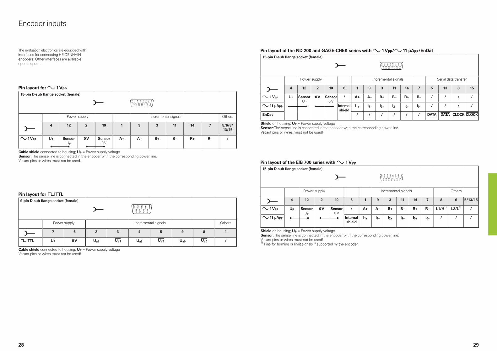
The evaluation electronics are equipped with interfaces for connecting HEIDENHAIN encoders. Other interfaces are available upon request.
Pin layout for » 1 VPP
15-pin D-sub flange socket (female)
Power supply Incremental signals Others
4 12 2 10 1 9 3 11 14 7 5/6/8/13/15
» 1 VPP UP SensorUP
0 V Sensor0 V
A+ A– B+ B– R+ R– /
Cable shield connected to housing; UP = Power supply voltageSensor: The sense line is connected in the encoder with the corresponding power line.Vacant pins or wires must not be used.
Pin layout for « TTL9-pin D-sub flange socket (female)
Power supply Incremental signals Others
7 6 2 3 4 5 9 8 1
« TTL UP 0 V Ua1 ¢ Ua2 £ Ua0 ¤ /
Cable shield connected to housing; UP = Power supply voltageVacant pins or wires must not be used!
Pin layout of the ND 200 and GAGE-CHEK series with » 1 VPP/» 11 µAPP/EnDat15-pin D-sub flange socket (female)
Power supply Incremental signals Serial data transfer
4 12 2 10 6 1 9 3 11 14 7 5 13 8 15
» 1 VPP UP SensorUP
0 V Sensor0 V
/ A+ A– B+ B– R+ R– / / / /
» 11 µAPP Internal shield
I1+ I1– I2+ I2– I0+ I0– / / / /
EnDat / / / / / / DATA DATA CLOCK CLOCK
Shield on housing; UP = Power supply voltageSensor: The sense line is connected in the encoder with the corresponding power line.Vacant pins or wires must not be used!
Pin layout of the EIB 700 series with » 1 VPP
15-pin D-sub flange socket (female)
Power supply Incremental signals Others
4 12 2 10 6 1 9 3 11 14 7 8 6 5/13/15
» 1 VPP UP SensorUP
0 V Sensor0 V
/ A+ A– B+ B– R+ R– L1/H1) L2/L1) /
» 11 µAPP Internal shield
I1+ I1– I2+ I2– I0+ I0– / / /
Shield on housing; UP = Power supply voltageSensor: The sense line is connected in the encoder with the corresponding power line.Vacant pins or wires must not be used!1) Pins for homing or limit signals if supported by the encoder

3130
Pin layout of the EIB 700 series with EnDat15-pin D-sub flange socket (female)
Power supply Incremental signals1) Serial data transfer Others
4 12 2 10 6 1 9 3 11 5 13 8 15 7/14
EnDat UP SensorUP
0 V Sensor0 V
Internal shield
A+ A– B+ B– DATA DATA CLOCK CLOCK /
Shield on housing; UP = Power supply voltageSensor: The sense line is connected in the encoder with the corresponding power line.Vacant pins or wires must not be used!1) For encoders with ordering designations EnDat01 and EnDat02
Pin layout of the IK 22015-pin D-sub flange socket (male)
Power supply Incremental signals Serial data transfer
1 9 2 11 13 3 4 6 7 10 12 5 8 14 15
11 µAPP UP5 V
Sensor5 V
UN0 V
Sensor0 V
Internal shield
I1+ I1– I2+ I2– I0+ I0– / / / /
1 VPP A+ A– B+ B– R+ R– / / / /
EnDatSSI
A+ A– B+ B– / / DATA DATA CLOCK CLOCK
Shield on connector housingVacant pins or wires must not be used.
EIB application software for the EIB 700
The EIB application software covers two applications:
Configuring and demonstrating the EIB 700• Easy configuration of settings required
for operating the EIB 700 (e.g., input interface, data packets, operating mode, trigger settings)
• Management of one or more EIB 700 units
• Simple depiction of the positions transmitted by the EIB 700
• Saving of settings for management of different application projects
For more information, please refer to the User’s Guide.
Platform for customized applicationsThe EIB application software is provided as source code, thereby allowing customers to rapidly implement their own applications. The application software was programmed using C++/CLI and Windows Forms in Visual Studio 2008. This programming environment is widely used in technical application programming but does not necessarily provide state-of-the-art user interfaces such as those in Windows 10. However, adaptation to other graphical interfaces can be performed by the customer.

NZ Llama ENGINEERING Ltd5012 Wellington, New Zealand E-mail: [email protected]
PH MACHINEBANKS' CORPORATIONQuezon City, Philippines 1113 E-mail: [email protected]
PL APS02-384 Warszawa, Poland www.heidenhain.pl
PT FARRESA ELECTRÓNICA, LDA.4470 - 177 Maia, Portugal www.farresa.pt
RO HEIDENHAIN Reprezentanta RomaniaBrasov, 500407, Romania www.heidenhain.ro
RS Serbia BG
RU GERTNER Service119002 Moscow, Russian Federation www.heidenhain.ru
SE HEIDENHAIN Scandinavia AB12739 Skärholmen, Sweden www.heidenhain.se
SG HEIDENHAIN PACIFIC PTE LTDSingapore 408593 www.heidenhain.com.sg
SK KOPRETINA TN s.r.o.91101 Trencin, Slovakia www.kopretina.sk
SL NAVO d.o.o.2000 Maribor, Slovenia www.heidenhain.si
TH HEIDENHAIN (THAILAND) LTDBangkok 10250, Thailand www.heidenhain.co.th
TR T&M Mühendislik San. ve Tic. LTD. STI·.
34775 Y. Dudullu – Ümraniye-Istanbul, Turkey www.heidenhain.com.tr
TW HEIDENHAIN CO., LTD.Taichung 40768, Taiwan www.heidenhain.com.tw
UA GERTNER Service 02094 Kiev, Ukraine www.heidenhain.ua
US HEIDENHAIN CORPORATIONSchaumburg, IL 60173-5337, USA www.heidenhain.us
VN AMS Co. LtdHCM City, VietnamE-mail: [email protected]
ZA MAFEMA SALES SERVICES C.C.Kyalami 1684, South Africa www.heidenhain.co.za
DK Denmark SE
ES FARRESA ELECTRONICA S.A.08028 Barcelona, Spain www.farresa.es
FI HEIDENHAIN Scandinavia AB01740 Vantaa, Finland www.heidenhain.fi
FR HEIDENHAIN FRANCE sarl92310 Sèvres, France www.heidenhain.fr
GB HEIDENHAIN (G.B.) LimitedBurgess Hill RH15 9RD, United Kingdom www.heidenhain.co.uk
GR MB Milionis Vassilis17341 Athens, Greece www.heidenhain.gr
HR Croatia SL
HU HEIDENHAIN Kereskedelmi Képviselet1239 Budapest, Hungary www.heidenhain.hu
ID PT Servitama Era ToolsindoJakarta 13930, Indonesia E-mail: [email protected]
IL NEUMO VARGUS MARKETING LTD.Holon, 5885948, Israel E-mail: [email protected]
IN HEIDENHAIN Optics & Electronics India Private LimitedChetpet, Chennai 600 031, India www.heidenhain.in
IT HEIDENHAIN ITALIANA S.r.l.20128 Milano, Italy www.heidenhain.it
JP HEIDENHAIN K.K.Tokyo 102-0083, Japan www.heidenhain.co.jp
KR HEIDENHAIN Korea Ltd.Anyang-si, Gyeonggi-do, 14087 South Korea www.heidenhain.co.kr
MX HEIDENHAIN CORPORATION MEXICO20290 Aguascalientes, AGS., Mexico E-mail: [email protected]
MY ISOSERVE SDN. BHD.43200 Balakong, Selangor E-mail: [email protected]
NL HEIDENHAIN NEDERLAND B.V.6716 BM Ede, Netherlands www.heidenhain.nl
NO HEIDENHAIN Scandinavia AB7300 Orkanger, Norway www.heidenhain.no
AR NAKASE SRL.B1653AOX Villa Ballester, Argentina www.heidenhain.com.ar
AT HEIDENHAIN Techn. Büro Österreich83301 Traunreut, Germany www.heidenhain.de
AU FCR MOTION TECHNOLOGY PTY LTDLaverton North Victoria 3026, Australia E-mail: [email protected]
BE HEIDENHAIN NV1760 Roosdaal, Belgium www.heidenhain.be
BG ESD Bulgaria Ltd.Sofia 1172, Bulgaria www.esd.bg
BR HEIDENHAIN Brasil Ltda.04763-070 – São Paulo – SP, Brazil www.heidenhain.com.br
BY GERTNER Service220026 Minsk, Belarus www.heidenhain.by
CA HEIDENHAIN CORPORATIONMississauga, OntarioL5T2N2, Canada www.heidenhain.com
CH HEIDENHAIN (SCHWEIZ) AG8603 Schwerzenbach, Switzerland www.heidenhain.ch
CN DR. JOHANNES HEIDENHAIN (CHINA) Co., Ltd.Beijing 101312, China www.heidenhain.com.cn
CZ HEIDENHAIN s.r.o.102 00 Praha 10, Czech Republic www.heidenhain.cz
DE HEIDENHAIN Vertrieb Deutschland83301 Traunreut, Deutschland 08669 31-3132| 08669 32-3132E-Mail: [email protected]
HEIDENHAIN Technisches Büro Nord12681 Berlin, Deutschland 030 54705-240
HEIDENHAIN Technisches Büro Mitte07751 Jena, Deutschland 03641 4728-250
HEIDENHAIN Technisches Büro West44379 Dortmund, Deutschland 0231 618083-0
HEIDENHAIN Technisches Büro Südwest70771 Leinfelden-Echterdingen, Deutschland 0711 993395-0
HEIDENHAIN Technisches Büro Südost83301 Traunreut, Deutschland 08669 31-1337
1102714-28 · 5 · 05/2021 · F&W · Printed in Germany
Vollständige und weitere Adressen siehe www.heidenhain.de For complete and further addresses see www.heidenhain.de
����������������������������������������������������������� ���� ���������������� ����������� ��������� �����������������������������
����������������