Embed Size (px)
Citation preview
EVALUATING MITIGATION METHODS FOR CHLORIDE INDUCED CORROSION OF
REINFORCED CONCRETE STRUCTURES
B.H.J. Pushpakumara
Research Student
Department of Civil and Environmental Engineering, Faculty of Engineering, University of
Ruhuna
Email: [email protected]
G. Sudeera De Silva
Senior Lecturer
Department of Civil and Environmental Engineering, Faculty of Engineering, University of
Ruhuna
Email: [email protected]
G.H.M.J. Subashi De Silva
Senior Lecturer, Department of Civil and Environmental Engineering, Faculty of Engineering,
University of Ruhuna
Email: [email protected]
Abstract
Corrosion of steel reinforcement in concrete causes the deterioration of concrete structures. As a
result, the corrosion loss consumes considerable portion of the budget of a country by ways of
either restoration measures or reconstruction. Once the corrosion signs appear, it may be too
late to prevent further deterioration and no proper method to re-passivate the corroded
reinforcement steel. Properly monitoring the structures for corrosion performance and taking
suitable measures at the appropriate time could contribute enormous saving.
Objective of this study is to evaluate the repairing methods for Reinforced Concrete (RC)
structures, which were corroded due to chloride attack. Laboratory experiments were conducted
with RC beams. The beams were cast by using Grade 20 concrete and steel bars of 16 mm
diameter. Cathodic protection and electrochemical chloride ion extraction were used as
treatment methods. For both methods, current was supplied by using DC power supply. The
positive and negative terminals were connected to the copper mesh laid on concrete surface and
steel reinforcement bars of beams, respectively. For electrochemical method, calcium hydroxide
was used as an electrolyte media. Cathodic protection and electrochemical chloride ion
extraction treatment remove 49.33% and 68.53% of total chloride ions from the embedded steel
reinforcement bar area, respectively. Catholic protection method prevented the further corrosion
possibly by removing the chloride ions, producing alkaline condition, which helps to form iron
oxide film surrounding the steel bars. With the electrochemical chloride ion extraction method,
calcium hydroxide helps to increase the efficiency of cathodic protection by removing the
chloride ions, which approached to the copper mesh, and by reducing the time duration of
cathodic protection.
Keywords: reinforced concrete, chloride attack, corrosion, repair methods, cathodic protection

1. Introduction
Corrosion of embedded steel reinforcement bars has been established as the predominant factor
causing deterioration of reinforced concrete structures in worldwide, especially of the structures
located at coastal marine environment. In Sri Lanka, most of reinforced concrete structures,
including Reinforced Concrete (RC) and Pre-stressed Concrete (PC) bridges are situated near
coastal belt. Figure 1 shows a few examples of current conditions of Sri Lankan RC structures,
which were deteriorated due to chloride attack. The concrete clear cover of these structures is
cracking and delaminating. In addition, the embedded steel reinforcements are exposed to the
severe environmental condition, prevailing in coastal region.
After initiating corrosion, the corrosion products (iron oxides and hydroxides) are usually
deposited in concrete around steel reinforcements. These corrosion products are more than six
times as voluminous as the steel (Hansson et al., 2007). Their formation within this restricted
space sets up expansive stresses, which cause signs of deteriorations (i.e., rusting, cracking,
spalling and delaminating) usually appear on the concrete surface (Veerachai et al., 2005). This
in turn results in progressive deterioration of the concrete. Presence of chloride ion is probably
responsible for most of the structural deteriorations caused by the corrosion of steel
reinforcement.
Concrete is alkaline due to the presence of Ca(OH)2, KOH, NaOH and the pH value is usually
above 12 (Jerzy, 1998). Because of the alkalinity of concrete, the embedded steel
reinforcements are passivated and formed iron oxide (Fe2O3) film surrounding the steel
reinforcement bars (Hansson et al., 2007). Due to the formation of this iron oxide film, the
diffusion of oxygen to surface of steel reinforcement bars is reduced. As a result, rate of
corrosion also reduced. This iron oxide film is thermodynamically stable as long as the pH
value of concrete remains above 11.5 (Jerzy, 1998). However, small amount of chloride ion
(Cl-) can weaken this film and initiate the corrosion (Jerzy, 1998). Corrosion of steel
reinforcement bars is an electrochemical process, which needs an anode, a cathode, a metallic
path and electrolytes. Oxidation occurs at the anode area of the surface of steel bar while
reduction occurs at the cathode area of the surface of steel bar (Hansson et al., 2007).
The service life of RC structures can be increased by applying necessary treatments
periodically. The application of treatment methods depends on several factors including current
condition of RC structures, required level of treatment, cost and availability of the treatment and
environmental conditions. Cathodic protection, electrochemical chloride ion extraction, repair
mortars, hydrophobic treatments, anti corrosion paints, corrosion inhibitors and water proof
membranes can be used as treatment methods for corrosion.
Figure 1: Existing corroded structures

Among, the above mentioned treatment methods, cathodic protection is the most effective
method for the corroded reinforced concrete structures. Cathodic protection works by using
current, to shift the potential of reinforcing steel in negative direction. If the potential is shifted
far enough so that all of the steel reinforcement becomes cathodic, corrosion will be stopped.
An advantage of using cathodic protection as a repair method for reinforced concrete structures
is that only spalls and detached concrete need to be repaired. Chloride contaminated concrete
that is still sound can remain in place because the cathodic protection system prevents further
corrosion and in fact, reduces the concentration of chloride ions adjacent to the protected
reinforcing bars. A cathodic protection system for reinforced concrete consists of a number of
basic components, including the reinforcement to be protected, an anode, a power source, a
monitoring system, cabling to carry the system power and monitoring signals (Jennifer et al.,
2000). The positive terminal of the power source is connected to the anode, and the negative
terminal is connected to the steel reinforcement bars, which becomes the cathode. A small
amount of direct current (DC) is then applied, causing current to flow through the electrolyte
from the anode to the reinforcement, making the reinforcement as cathodic in relation to the
anode.
The electrochemical chloride ion extraction method is similar to the cathodic protection method
except the anode is placed in the electrolyte media for the purpose of absorbing and removing of
chloride ions, which approached to the anode (i.e., concrete surface). The electrochemical
chloride ion extraction method is a new technology and it accelerates the cathodic protection by
removing the chloride ions effectively. The electrolyte media can be any of a number of
different solutions such as saturated calcium hydroxide, sodium borate, sodium hydroxide or tap
water. If the electrolyte is an alkaline solution, the hydroxyl ions are converted to oxygen gas
and water at the anode. If the electrolyte is a relatively neutral solution, such as water, the water
is converted into oxygen gas and hydrogen ions at the anode. These hydrogen ions combine
with the hydroxide ions to form water, and with the chloride ions to form hydrochloric acid.
Excess chloride ions are released in the form of chlorine gas at the anode. The reactions in
natural solutions are not desirable because hydrochloric acid attacks the concrete and chlorine
gas constitutes a health hazard. As a result, an alkaline electrolyte is usually used. These
treatments remove around 20-50% of the chloride ions from the concrete, and also redistribute
the remains away from the reinforcement (Clemena and Jackson, 1996).
However, in Sri Lanka, the application of treatment methods to prevent and minimize the
corrosion of existing RC structures is not often done. As a result, authorities have to pay more
funds for repairing the structures, which are under critical conditions. The introduction of
repairing and retrofitting methods for existing corroded reinforced concrete structures are
highly required for Sri Lanka. In this study, the effectiveness of the cathodic protection method
and the electrochemical chloride ion extraction method are evaluated based on laboratory
experiments. The comparisons of above treatment methods are also studied. The use of calcium
hydroxide (hydrated lime) as electrolyte media is a new concept of electrochemical chloride ion
extraction method.
2. Methodology
The corrosion process of RC beams was accelerated by using Accelerated Corrosion Test
Method (ACTM). Eight reinforced concrete beams having the sizes of 400 mm x 100 mm x 150
mm were cast using Grade 20 concrete. Four steel reinforcement bars with the diameter of 16
mm were embedded into each beam as shown in Figure 2(a). A reinforcement cage was
prepared by using three stirrups with the diameter of 6 mm. The cover depth was kept as 20
mm. Two wires were set to each beam for the purpose of applying current to the beams during
experiments as shown in Figure 2(b). All beams were cast using continuous moulds as shown in
Figure 2(c).
Stage 1: All eight RC beams were immersed in a tank for 28 days curing. After curing, one
beam was tested to determine total and free chloride concentration and rust production.
Stage 2: The other seven beams were subjected to accelerated corrosion test method (ACTM)
and the ACTM was carried out with monitoring the current, until the 0.2 mm wide corrosion
crack was appeared in the concrete surface. After the crack was attained, one of seven beams
was again tested to determine total and free chloride concentration and rust production.
Stage 3: Then, protection methods were applied to four of the remained six beams: two beams
for cathodic protection and two beams for electrochemical chloride ion extraction. Other two
beams were used as control beams. After completion of both treatments, one beam from each
treatment method and one of control beams were tested for total and free chloride concentration
measurements and rust production measurements. The other remaining treated two beams and
the remaining control beam were again subjected to ACTM and the time duration for
propagation of the corrosion crack of beams (crack width of 0.2 mm) was measured.
2.1 Accelerated corrosion test method (ACTM)
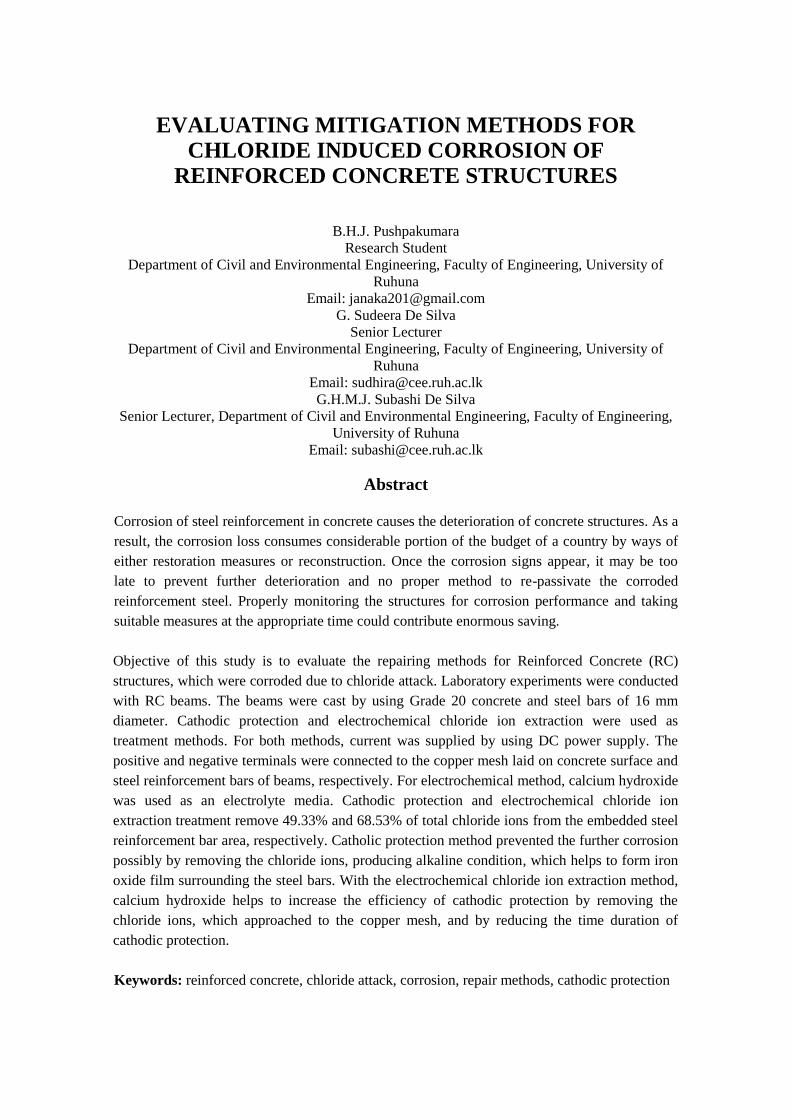
This test was based on electrochemical polarization principle. The experimental setup (Figure
3(a)) essentially consisted of a non-metallic container. Sea water with higher Cl- concentration
(i.e., concentration of Cl- was improved up to 5% of sea water), was filled up to the required
level of the container.
Figure 3: Accelerated corrosion test procedure
(a) Direct current was supplied (b) Corroded beam (c) Measuring the crack width
Figure 2: (a) Steel r/f cage (b) Wires were set to beams (c) Concreting beams
(c)
(b)
(a)
(c)
(a)
(b)
The RC specimens were immersed in this container. The reinforcement bars of the concrete
specimen were connected to the positive (+) terminal and the copper electrode was connected to
the negative (-) terminal of the DC power supply. This set up formed an electrochemical cell
(one RC test beam) with reinforcement bar acting as anode and copper electrode acting as
cathode. Similar units (RC test beams) were made and connected to a DC power supply of
multi-channel system as shown in Figure 3(b). A constant voltage of 5.0 V was applied from the
DC power supply. Width of the corrosion crack was monitored with time as shown in Figure
3(c), until the crack width of 0.2 mm was attained.
2.2 Cathodic protection method
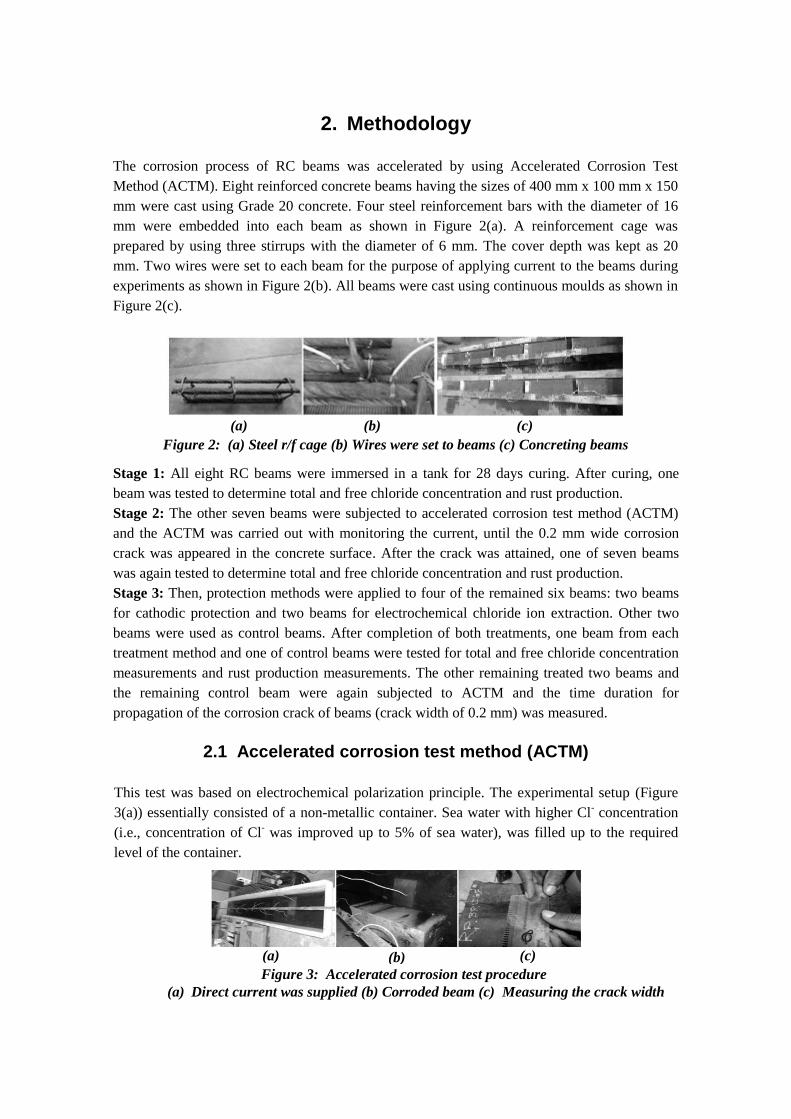
As described in the methodology section (Stage 3), two beams were subjected to cathodic
protection method. Copper meshes were connected to 400 mm x 150 mm surface of the test
beams as shown in Figure 4(a). This surface of beam was covered by using wet sags as shown
in Figure 4(b), for the purpose of touching the meshes to concrete surface well and conducting
current throughout the surface. The positive terminal of the DC power supply was connected to
the copper mesh and the negative terminal was connected to the steel reinforcement. Initially,
0.5 A current was supplied to the system and 11.5 V voltage difference was observed.
A constant voltage difference (i.e., 11.5 V) was applied to the system and the current was
monitored (from the initial reading of 0.5 A) with time until a negligible current reading (up to
0.05 A) was obtained. Because the copper mesh acted as sacrificial anode, with time it was
dissolved. After dissolving first mesh, the cathodic protection treatment was continued with
another identical copper mesh. Then, one of the treated beams and a control beam were tested
for total and free chloride ion concentration measurements and rust production measurement.
The other treated beam was subjected to ACTM and the time taken to initiate the corrosion
crack (i.e., 0.2 mm wide crack) was measured.
2.3 Electrochemical chloride ion extraction method
Figure 4: Cathodic protection treatment procedure
(a) Copper mesh was fixed (b) Wet sags were laid on the beams
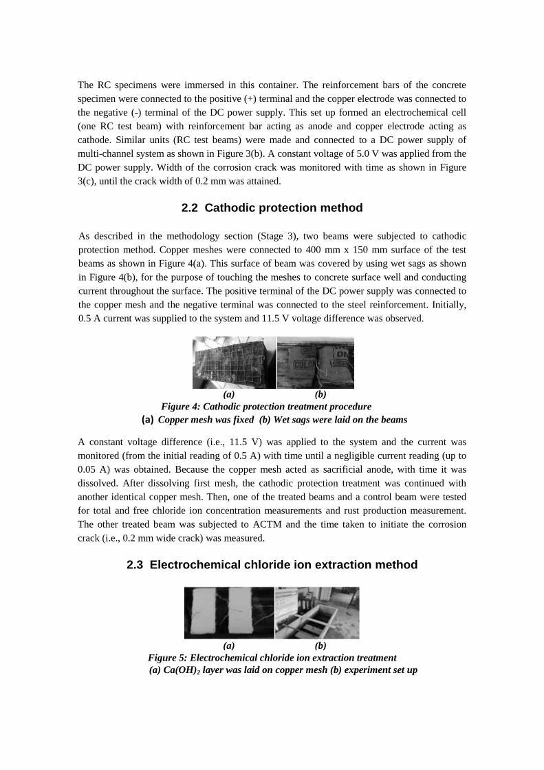
Figure 5: Electrochemical chloride ion extraction treatment
(a) Ca(OH)2 layer was laid on copper mesh (b) experiment set up
(a)
(b)
(a)
(b)
The electrochemical chloride ion extraction method is similar to cathodic protection method
except the copper mesh laid on concrete surface was covered by using a 5 mm thick layer of
hydrated lime (Ca(OH)2). With a constant voltage difference (i.e., 11.5 V), current was
monitored with time until a negligible current reading was attained. After dissolving first mesh,
the electrochemical treatment was also continued with another identical copper mesh and with
new layer of Ca(OH)2. After the negligible current reading was obtained, one of the treated
beams and a control beam (same beam which used in cathodic protection) was tested for total
and free chloride ion concentration measurements and rust production measurement. The other
treated beam was subjected to ACTM and the time taken to initiate the corrosion crack (i.e., 0.2
mm wide crack) was measured.
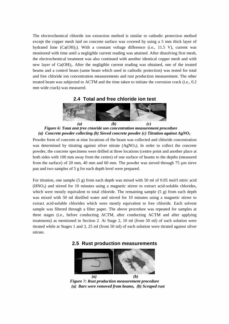
2.4 Total and free chloride ion test
Powder form of concrete at nine locations of the beam was collected and chloride concentration
was determined by titrating against silver nitrate (AgNO3). In order to collect the concrete
powder, the concrete specimens were drilled at three locations (centre point and another place at
both sides with 100 mm away from the centre) of one surface of beams to the depths (measured
from the surface) of 20 mm, 40 mm and 60 mm. The powder was sieved through 75 µm sieve
pan and two samples of 5 g for each depth level were prepared.
For titration, one sample (5 g) from each depth was mixed with 50 ml of 0.05 mol/l nitric acid
(HNO3) and stirred for 10 minutes using a magnetic stirrer to extract acid-soluble chlorides,
which were mostly equivalent to total chloride. The remaining sample (5 g) from each depth
was mixed with 50 ml distilled water and stirred for 10 minutes using a magnetic stirrer to
extract acid-soluble chlorides which were mostly equivalent to free chloride. Each solvent
sample was filtered through a filter paper. The above procedure was repeated for samples at
three stages (i.e., before conducting ACTM, after conducting ACTM and after applying
treatments) as mentioned in Section 2. At Stage 2, 10 ml (from 50 ml) of each solution were
titrated while at Stages 1 and 3, 25 ml (from 50 ml) of each solution were titrated against silver
nitrate.
2.5 Rust production measurements
Figure 6: Total and free chloride ion concentration measurement procedure
(a) Concrete powder collecting (b) Sieved concrete powder (c) Titration against AgNO3
(c)
(b)
(a)
Figure 7: Rust production measurement procedure
(a) Bars were removed from beams, (b) Scraped rust
(b)
(a)
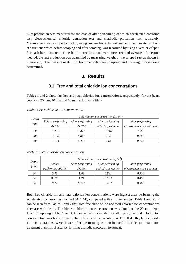
Rust production was measured for the case of after performing of which accelerated corrosion
test, electrochemical chloride extraction test and chathodic protection test, separately.
Measurement was also performed by using two methods. In first method, the diameter of bars,
at situations which before scraping and after scraping, was measured by using a vernier caliper.
For each bar, diameters of the bar at three locations were measured and averaged. In second
method, the rust production was quantified by measuring weight of the scraped rust as shown in
Figure 7(b). The measurements from both methods were compared and the weight losses were
determined.
3. Results
3.1 Free and total chloride ion concentrations
Tables 1 and 2 show the free and total chloride ion concentrations, respectively, for the beam
depths of 20 mm, 40 mm and 60 mm at four conditions.
Table 1: Free chloride ion concentration
Depth
(mm)
Chloride ion concentration (kg/m3)
Before performing
ACTM
After performing
ACTM
After performing
cathodic protection
After performing
electrochemical treatment
20 0.282 1.471 0.346 0.25
40 0.198 0.841 0.23 0.202
60 0.124 0.431 0.13 0.122
Table 2: Total chloride ion concentration
Depth
(mm)
Chloride ion concentration (kg/m3)
Before
Performing ACTM
After performing
ACTM
After performing
cathodic protection
After performing
electrochemical treatment
20 0.41 1.64 0.831 0.516
40 0.335 1.24 0.533 0.456
60 0.24 0.771 0.407 0.368
Both free chloride ion and total chloride ion concentrations were highest after performing the
accelerated corrosion test method (ACTM), compared with all other stages (Table 1 and 2). It
can be seen from Tables 1 and 2 that both free chloride ion and total chloride ion concentrations
decrease with depth. The highest chloride ion concentration was found at the 20 mm depth
level. Comparing Tables 1 and 2, it can be clearly seen that for all depths, the total chloride ion
concentration was higher than the free chloride ion concentration. For all depths, both chloride
ion concentrations were lower after performing electrochemical chloride ion extraction
treatment than that of after performing cathodic protection treatment.
3.2 Rust production measurements
Table 3: Weight of the rust with bar diameter
Inspection
Stage Ba
r (#
)
Bar diameter (mm) Weight of bars (g)
Ru
st p
rod
uct
ion
(g)
Ave
rag
e ru
st
pro
du
ctio
n (
g)
Rea
din
g 1
Rea
din
g 2
Rea
din
g 3
Ave
rag
e
(ea
ch b
ar)
Ave
rag
e
Bef
ore
rem
ovi
ng
rust
Aft
er
rem
ovi
ng
rust
After
performing
ACTM
1 15.4 15.5 15.5 15.47
15.56
526 523 3
3.5 2 15.9 15.4 15.9 15.73 548 544 4
3 14.9 15.5 15.7 15.37 539 535 4
4 15.5 15.8 15.8 15.7 499 496 3
After
performing
cathodic
protection
treatment
1 15.7 15.3 15.4 15.47
15.48
553 549 4
4
2 15.7 15.3 15.6 15.53 532 528 4
3 15.4 15.5 15.2 15.37 557 552 5
4 15.7 15.4 15.6 15.57 556 553 3
After
performing
electrochemical
treatment
1 16.1 15.6 15.4 15.7
15.53
518 515 3
3.75 2 15.4 15.6 15.2 15.4 537 532 5
3 15.3 15.5 15.6 15.47 527 524 3
4 15.4 15.7 15.5 15.53 519 515 4
Table 3 shows the rust production of steel reinforcement bars for the stages of after conducting
ACTM, after performing cathodic protection and electrochemical treatment. After applying the
treatments, the amount of the rust was slightly increasing while the diameter of the bar was
slightly decreasing compared to after performing ACTM conditions. The rust amount increment
was 0.5 g for cathodic protection treatment and 0.25 g for electrochemical treatment. The
amount of rust production of electrochemical treatment was lower than that of cathodic
protection. The reduction in the bar diameter for cathodic protection was 0.08 mm while it was
0.03 mm for electrochemical treatment. The reduction in the bar diameter after applying the
electrochemical treatment was also lower than that of after applying the cathodic protection.
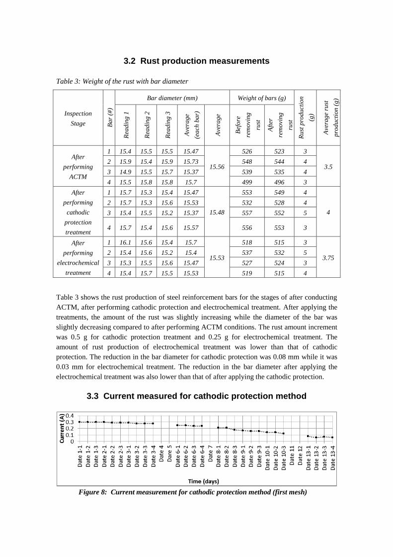
3.3 Current measured for cathodic protection method
Figure 8: Current measurement for cathodic protection method (first mesh)

Figures 8 and 9 show the current reading (versus time) of cathodic protection treatment. The
treatment was conducted over 31 days. Initial current reading for first mesh was observed as 0.3
A (Figure 8). Initial current reading for second mesh was observed as 0.23 A (Figure 9) and for
the third mesh initial current reading was observed as 0.16 A. Therefore the total current
reduction was 0.14 A.
Figures 10 and 11 show the current with time for the electrochemical treatment method. The
electrochemical chloride ion extraction treatment was conducted over 23 days. For the constant
voltage of 11.5 V, the initial current was observed as 0.5 A (Figure 10). From the monitoring
process of the current, the negligible current reading for first copper mesh was observed after 8
days. After fixing the second mesh the initial current was found as 0.29 A (Figure 11). The
treatment was continued for another 15 days with the second mesh. With fixing of the third
mesh at the right time (i.e., after the negligible current reading for the second mesh was
obtained) the initial current reading was observed as 0.17 A. The total current reduction was
found as 0.33 A.
Figure 11: Current measurement for electrochemical treatment method (second mesh)
Figure 10: Current measurement for electrochemical treatment method (first mesh)
Figure 9: Current measurement for cathodic protection method (second mesh)
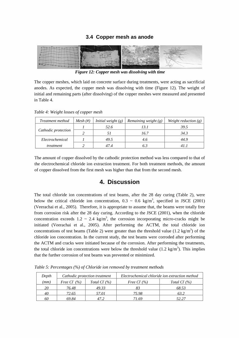
3.4 Copper mesh as anode
The copper meshes, which laid on concrete surface during treatments, were acting as sacrificial
anodes. As expected, the copper mesh was dissolving with time (Figure 12). The weight of
initial and remaining parts (after dissolving) of the copper meshes were measured and presented
in Table 4.
Table 4: Weight losses of copper mesh
Treatment method Mesh (#) Initial weight (g) Remaining weight (g) Weight reduction (g)
Cathodic protection 1 52.6 13.1 39.5
2 51 16.7 34.3
Electrochemical
treatment
1 49.5 4.6 44.9
2 47.4 6.3 41.1
The amount of copper dissolved by the cathodic protection method was less compared to that of
the electrochemical chloride ion extraction treatment. For both treatment methods, the amount
of copper dissolved from the first mesh was higher than that from the second mesh.
4. Discussion
The total chloride ion concentrations of test beams, after the 28 day curing (Table 2), were
below the critical chloride ion concentration, 0.3 ~ 0.6 kg/m3, specified in JSCE (2001)
(Veerachai et al., 2005). Therefore, it is appropriate to assume that, the beams were totally free
from corrosion risk after the 28 day curing. According to the JSCE (2001), when the chloride
concentration exceeds 1.2 ~ 2.4 kg/m3, the corrosion incorporating micro-cracks might be
initiated (Veerachai et al., 2005). After performing the ACTM, the total chloride ion
concentrations of test beams (Table 2) were greater than the threshold value (1.2 kg/m3) of the
chloride ion concentration. In the current study, the test beams were corroded after performing
the ACTM and cracks were initiated because of the corrosion. After performing the treatments,
the total chloride ion concentrations were below the threshold value (1.2 kg/m3). This implies
that the further corrosion of test beams was prevented or minimized.
Table 5: Percentages (%) of Chloride ion removed by treatment methods
Depth
(mm)
Cathodic protection treatment Electrochemical chloride ion extraction method
Free Cl-
(%) Total Cl- (%) Free Cl
- (%) Total Cl
- (%)
20 76.48 49.33 83 68.53
40 72.65 57.01 75.98 63.2
60 69.84 47.2 71.69 52.27
Figure 12: Copper mesh was dissolving with time

The most critical depth region related to corrosion was found as less than 20 mm, because steel
reinforcements were embedded to the depth of 20 mm. In this region, the electrochemical
treatment removed 68.53% of total and 83% of free chloride ions from the corroded beams (i.e.,
after performing ACTM) while the cathodic protection treatment removed 49.33% of total and
76.48% of free chloride ions (Table 5). When the current was supplied to the cathodic
protection setup, the steel reinforcement became cathode and the chloride ions were
redistributed away from the steel bars and reached towards the copper anode (at concrete
surface area). This might contribute to the reduction in the chloride ion concentration near to the
steel reinforcements. In electrochemical chloride ion extraction treatment, the copper mesh was
covered by using electrolyte media (calcium hydroxide) and the chloride ions which approached
to the copper mesh were removed by calcium hydroxide producing CaCl2. It implies the
efficiency of removing the chloride ion by electrochemical chloride ion extraction treatment
was higher than the cathodic protection treatment.
After performing the treatments, the free chloride ion concentration of test beams decreases
similar to the concentration observed at 28 day curing (Figure 13a). The treatment methods
were based on the electrical system and the free chloride ions were directly contribute to the
current. Therefore, admittedly, the free chloride ions were redistributed from steel
reinforcements and reached towards the concrete surface area. These free chloride ions were
removed by calcium hydroxide layer. On the other hand, free chloride ions caused the corrosion
of steel reinforcement. The bonded chloride ions did not contribute to the corrosion process.
Therefore, removing free chloride ions by these treatments is an advantage than removing
bonded chloride ions.
After performing the ACTM, 3.5 g of rust was produced. After applying the treatments, there
was little or no rust production. After electrochemical treatment 0.25 g of rust amount and after
cathodic protection 0.5 g of rust amount were additionally produced, compared to the rust
amount produced by ACTM. These increments of rust amounts (after treatments) were lower
compared to rust amount produced in corroded beam (Table 3). The reduction in the bar
Figure 13: a) Free chloride ion concentration (b) Total chloride ion concentrations
(a)
(b)

diameter was reduced after performing the treatments (Table 3) implying the treatment methods
minimized further corrosion.
The reduction in current of electrochemical and cathodic protection treatments also implied the
reduction in chloride ion concentration of test beams (Figures 8 to 11). The efficiency of
removing chloride ion for cathodic protection was 46.67% with respect to the reduction in
current (Figures 8 and 9). The efficiency of removing chloride ion for electrochemical treatment
was 66% with respect to the reduction in current (Figures 10 and 11). The cathodic protection
was conducted over 31 days while the electrochemical treatment was conducted over 23 days.
This indicates the electrochemical treatment required lesser time compared to the cathodic
protection. The amount of copper mesh dissolved was higher and dissolving rate was fast for
both methods (Table 4). This implies at the beginning, the rate of removing chloride from both
methods was higher. The dissolved amount of copper was higher for electrochemical treatment
than that of cathodic protection (Table 4). It can be concluded that, the dissolved amounts of
copper mesh were directly involved in to efficiency of treatments. However, it is necessary to
prevent the breakage of scattered places of mesh, in order to continue uniform current over the
treated area.
In the present study, calcium hydroxide was used as an electrolyte media. The calcium
hydroxide usually reacts with chloride ions and produce CaCl2. The use of calcium hydroxide
as an electrolyte media prevented the entering of chloride ions to RC beams by producing
calcium chloride. It also helped to prevent the further corrosion, as observed in the present
study. In the cathodic protection and the electrochemical treatment methods, the steel
reinforcement bar became cathode with time. When the steel reinforcement bars totally charged
with negative ions, further continuation of current might help to produce hydroxyl ions near to
reinforcement bars, caused to create alkaline conditions. Because of this alkalinity near
reinforcements, the steel reinforcements might have been repassivated and produced iron oxide
(Fe2O3) film surrounding the steel reinforcement bars, preventing the diffusion of oxygen to
steel bar area and hence preventing the further corrosion.
5. Conclusions
Introduction of treatment methods for corroded structures is highly needed to Sri Lanka,
because reconstruction of corroded structures consume large amount of annual budget. In this
study, effectiveness and efficiency of the electrochemical chloride ion extraction method and
cathodic protection treatment method for reinforced concrete (RC) beams, which were corroded
due to chloride attack, were evaluated. At the most critical depth interval, where steel
reinforcements were embedded, the electrochemical treatment removed 68.53% of total and
83% of free chloride ion from the corroded beams while the cathodic protection treatment
removed 49.33% of total and 76.48% of free chloride ions. The use of calcium hydroxide to
cover the copper mesh in electrochemical treatment enhances the efficiency of cathodic
protection by nearly 20% with respected to total chloride removal. With the calcium hydroxide
layer, the time duration for completion of treatment was reduced.
The use of cathodic protection prevents the further corrosion by removing chloride ions,
producing alkaline conditions around the steel bars, and helps to form iron oxide film around
steel bars. With electrochemical treatment method, the calcium hydroxide helps to increase the
efficiency of cathodic protection by removing the chloride ions, which are approached to copper
mesh area and reducing the time duration of cathodic protection.
Acknowledgement
The authors wish to express their special thanks to Research Grant (2011) of Transforming
University of Ruhuna to International Level for providing necessary funds and Faculty of
Engineering, University of Ruhuna for providing necessary technical assistance for carrying out
the research work presented in this paper.
References
Clemena G G and Jackson D R (1996) “Pilot Applications of Electrochemical Chloride
Extraction on Concrete piers in Virginia”, Interim Report, Transportation Research Council,
VTRC 96-IR 4, Charlottesville, Virginia, May 1996
Hansson C M, Poursaee A and Jaffer S J (2007) “Corrosion of Reinforcing Bars in Concrete”, R
& D Serial No. 3013, Portland Cement Association, Skokie, Illinois, USA
Jerzy Z (1998) “Modelling the Time to Corrosion Initiation for Concretes with Mineral
Admixtures and/or Corrosion Inhibitors in Chloride- Laden Environments”, Virginia
Polytechnic Institute and State University, Blacksburg, Virginia, January 1998
Jennifer L k, David D and Carl E L (2000), “Evaluation of corrosion protection methods for
reinforced concrete highway structures”, Structural Engineering and Engineering Materials,
SM Report No.58, University of Kansas Center for Research, Inc., Lawrence, Kansas, May
2000
Veerachai L, Toshimitsu S, Yuichi T and Masayasu O (2005), “Estimation of Corrosion in
Reinforced Concrete by Electrochemical Techniques and Acoustic Emission”, Journal of
Advanced Concrete Technology, Vol.3, No.1, February 2005, pp.137-147