Embed Size (px)
Citation preview
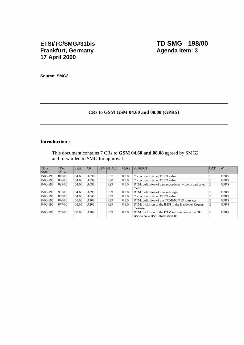
ETSI/TC/SMG#31bis TD SMG 198/00Frankfurt, Germany Agenda Item: 317 April 2000
Source: SMG2
CRs to GSM GSM 04.60 and 08.08 (GPRS)
Introduction :
This document contains 7 CRs to GSM 04.60 and 08.08 agreed by SMG2and forwarded to SMG for approval.
TDocSMG
TDocSMG2
SPEC CR REV PHASE VERS SUBJECT CAT W. I.
P-00-198 845/00 04.60 A838 R97 8.3.0 Correction to timer T3174 value F GPRSP-00-198 846/00 04.60 A839 R98 8.3.0 Correction to timer T3174 value F GPRSP-00-198 895/00 04.60 A098 R99 8.3.0 DTM: definition of new procedures while in dedicated
modeB GPRS
P-00-198 935/00 04.60 A099 R99 8.3.0 DTM: definition of new messages B GPRSP-00-198 847/00 04.60 A840 R99 8.3.0 Correction to timer T3174 value F GPRSP-00-198 876/00 08.08 A202 R99 8.3.0 DTM: definition of the COMMON ID message B GPRSP-00-198 877/00 08.08 A203 R99 8.3.0 DTM: inclusion of the IMSI in the Handover Request
messageB GPRS
P-00-198 785/00 08.08 A204 R99 8.3.0 DTM: inclusion of the DTM information in the OldBSS to New BSS Information IE
B GPRS

SMG2 #35Schaumburg, Illinois, U.S.A., 3-7 April 2000
Document 2-00-845Agenda Item 7.1.5.1
CHANGE REQUEST Please see embedded help file at the bottom of thispage for instructions on how to fill in this form correctly.
Current Version: 6.7.004.60 CR A838GSM (AA.BB) or 3G (AA.BBB) specification number ↑ ↑ CR number as allocated by MCC support team
For submission to: SMG #32 for approval X strategic (for SMGlist expected approval meeting # here
↑for information non-strategic X use only)
Form: CR cover sheet, version 2 for 3GPP and SMG The latest version of this form is available from: ftp://ftp.3gpp.org/Information/CR-Form-v2.doc
Proposed change affects: (U)SIM ME X UTRAN / Radio X Core Network(at least one should be marked with an X)
Source: Motorola, Inc. Date: 5 April 2000
Subject: Correction to timer T3174 value
Work item: GPRS
Category: F Correction X Release: Phase 2A Corresponds to a correction in an earlier release Release 96
(only one category B Addition of feature Release 97 Xshall be marked C Functional modification of feature Release 98with an X) D Editorial modification Release 99
Release 00
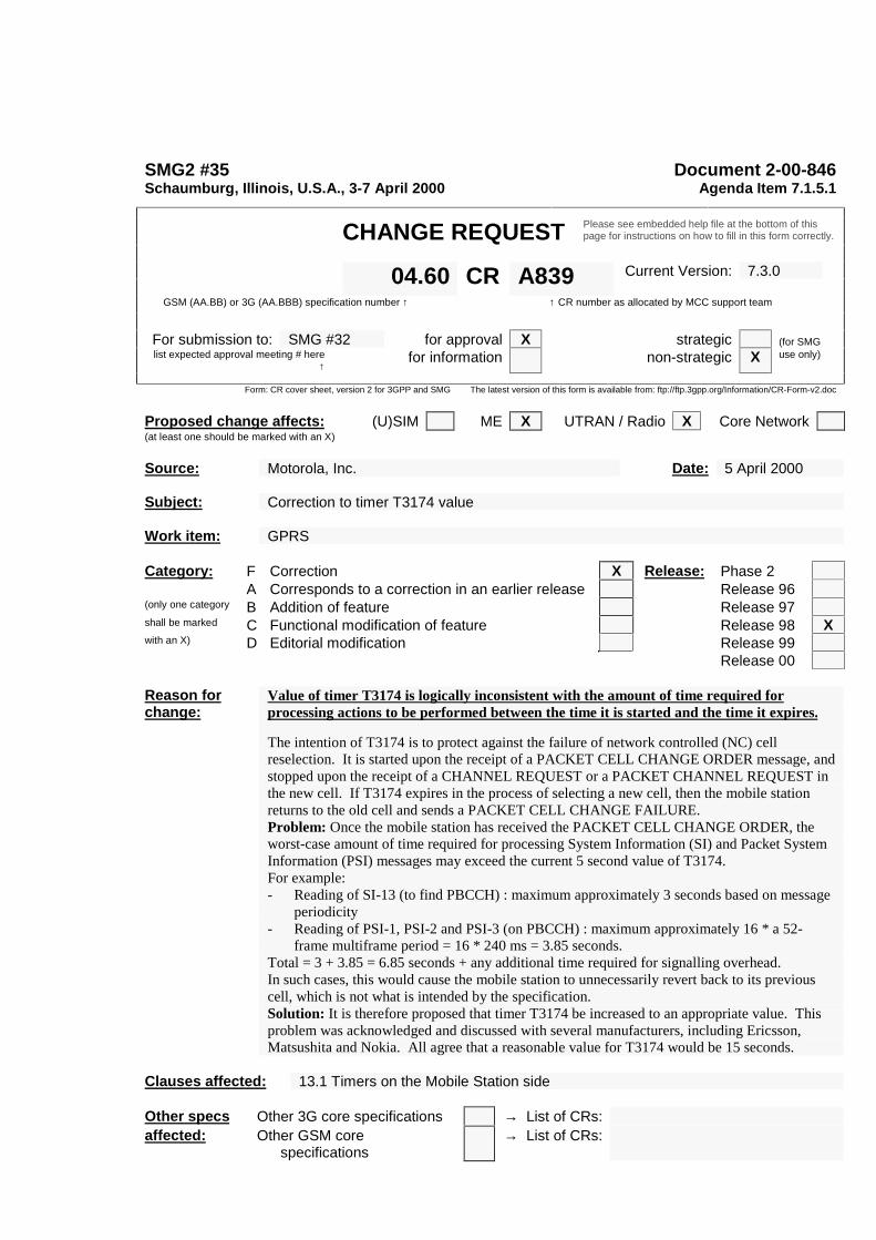
Reason forchange:
Value of timer T3174 is logically inconsistent with the amount of time required forprocessing actions to be performed between the time it is started and the time it expires.
The intention of T3174 is to protect against the failure of network controlled (NC) cellreselection. It is started upon the receipt of a PACKET CELL CHANGE ORDER message, andstopped upon the receipt of a CHANNEL REQUEST or a PACKET CHANNEL REQUEST inthe new cell. If T3174 expires in the process of selecting a new cell, then the mobile stationreturns to the old cell and sends a PACKET CELL CHANGE FAILURE.Problem: Once the mobile station has received the PACKET CELL CHANGE ORDER, theworst-case amount of time required for processing System Information (SI) and Packet SystemInformation (PSI) messages may exceed the current 5 second value of T3174.For example:- Reading of SI-13 (to find PBCCH) : maximum approximately 3 seconds based on message
periodicity- Reading of PSI-1, PSI-2 and PSI-3 (on PBCCH) : maximum approximately 16 * a 52-
frame multiframe period = 16 * 240 ms = 3.85 seconds.Total = 3 + 3.85 = 6.85 seconds + any additional time required for signalling overhead.In such cases, this would cause the mobile station to unnecessarily revert back to its previouscell, which is not what is intended by the specification.Solution: It is therefore proposed that timer T3174 be increased to an appropriate value. Thisproblem was acknowledged and discussed with several manufacturers, including Ericsson,Matsushita and Nokia. All agree that a reasonable value for T3174 would be 15 seconds.
Clauses affected: 13.1 Timers on the Mobile Station side
Other specs Other 3G core specifications → List of CRs:affected: Other GSM core
specifications→ List of CRs:

MS test specifications → List of CRs:BSS test specifications → List of CRs:O&M specifications → List of CRs:
Othercomments:

13.1 Timers on the Mobile Station side
Table 1: Specification of timers used in GPRS on the Mobile Station side
timer started stopped Action at expiry valueT3158 Started when ordered by a
NETWORK_CONTROL_ORDER and then restarted each timea Network Controlled (NC)Measurement is performed inMM Ready state and in packetidle or packet transfer mode
See 05.08 Restart the timer, perform themeasurement and send a NCMeasurement report. The timershall be restarted with either ofthe parametersNC_REPORTING_PERIOD_Iwhen in packet idle mode orwith the parameterNC_REPORTING_PERIOD_Twhen in packet transfer mode
Defined bytheparameteror by arandomvalue (seeGSM05.08)
T3162 On receipt of a PACKETQUEUING NOTIFICATION.
On receipt of a PACKETUPLINK ASSIGNMENT
Abort Packet access procedure;indicate Packet access failure toupper layers and Return topacket idle mode listening to itspaging subchannel
5 sec
T3164 On receipt of a PACKETUPLINK ASSIGNMENT
At sending of the first RLC/MACblock
See subclause 7.1.4. 5 sec
T3166 At sending of the first RLC/MACblock at one phase access
On receipt of a PACKETUPLINK ACK/NACK
Immediately stop transmitting onthe assigned TBF; a TBFestablishment failure hasoccurred or the contentionresolution procedures has failed
5 sec
T3168 At sending the PACKETRESOURCE REQUESTmessage or Channel RequestDescription IE in PACKETDOWNLINK ACK/NACK
On receipt of a PACKETUPLINK ASSIGNMENTmessage
Reinitiate the packet accessprocedure or retransmit thePACKET RESOURCEREQUEST or PACKETDOWNLINK ACK/NACK
assignedin systeminformation
T3170 After having made M + 1attempts to send a PACKETCHANNEL REQUESTmessage, or on receipt of aPACKET ACCESS REJECTmessage.
On receipt of a PACKETUPLINK ASSIGNMENT orPACKET QUEUINGNOTIFICATION message
Abort Packet access procedure,indicate Packet access failure toupper layer and return to PacketIdle mode
Defined byparameters TX_INTand S
T3172 On receipt of a PACKETACCESS REJECT message
On receipt of a PACKETUPLINK ASSIGNMENTmessage
Packet Access in the cell nolonger prohibited
assignedinmessage
Table 1 (continued): Specification of timers used in GPRS on the Mobile Station side
timer started stopped Action at expiry valueT3174 On receipt of a PACKET CELL
CHANGE ORDER messageOn receipt of a response toCHANNEL REQUEST orPACKET CHANNEL REQUESTin the new cell
Return to old cell and sendPACKET CELL CHANGEFAILURE
5 15 sec
T3176 Expiry of T3174 After sending of PACKET CELLCHANGE FAILURE message
Stop cell change order failureprocedure.
5 sec
T3178 Started when ordered by aEXT_MEASUREMENT_ORDERand then restarted each time anextended (EXT) Measurement isperformed in packet idle mode
See 05.08 Restart the timer, perform themeasurement and send an EXTMeasurement report. The timershall be restarted with theparameterEXT_REPORTING_PERIOD
Defined bytheparameteror by aRandomvalue (seeGSM05.08)
T3180 When transmitting an RLC/MACblock to the network
When detecting an assignedUSF value on assigned PDCH
Perform Abnormal release withrandom access procedure
5 sec
T3182 After sending the last data block(with CV = 0), or Upon detectinga transmit window stall condition
On receipt of the PACKETUPLINK ACK/NACK message
Abnormal release with randomaccess
5 sec
T3184 On receipt of a PACKETUPLINK ACK/NACK message
On receipt of PACKET UPLINKACK/NACK message(T3184 is also restarted)
Abnormal release with randomaccess
5 sec
T3186 When packet access procedureis started Stopped when receiving any
message from the network inresponse to the PACKETCHANNEL REQUEST messageor after M+1 attempts to sendPACKET CHANNEL REQUESTmessages on the PRACHchannel
Abort Packet access procedure;indicate Packet access failure toupper layers and return toPacket Idle mode.
5 sec
T3188 If a new fixed allocation hasbeen requested, when all datahas been sent on the assignedallocation
On receipt of PACKET UPLINKASSIGNMENT, PACKETUPLINK ACK/NACK messagecontaining a fixed allocation, orPACKET ACCESS REJECT
Resend the last allocationrequest if it needs more data tocomplete the TBF
5 sec
T3190 At reception of a downlinkassignment message
Restarted on receipt of data onthe resources
Abnormal release with return toCCCH or PCCCH
5 sec
T3192 At sending the PACKETDOWNLINK ACK/NACK withthe Final Ack Indicator=1, or atsending the PACKETCONTROL ACK as a responseto final RLC data block inunacknowledged mode.
Restarted at sending thePACKET DOWNLINKACK/NACK with the Final AckIndicator=1, or at sending thePACKET CONTROL ACK as aresponse to final RLC data blockin unacknowledged mode.Stopped at the reception of aPACKET DOWNLINKASSIGNMENT or PACKETTIMESLOT RECONFIGURE.
Release the resources, stopmonitoring the PDCHs, andbegin to monitor the pagingchannel
assignedin systeminformation
T3198 When transmitting RLC datablock
none Accept negativeacknowledgement for RLC datablock
see clause9.1.3
T3200 On receipt of an RLC/MACcontrol block containing asegment of an RLC/MAC controlmessage
On receipt of an RLC/MACcontrol block containing asegment of an RLC/MAC controlmessage such that the mobilestation now has the completecontrol message
Discard and ignore all segmentsof the partially receivedRLC/MAC control message
see clause9.1.11b
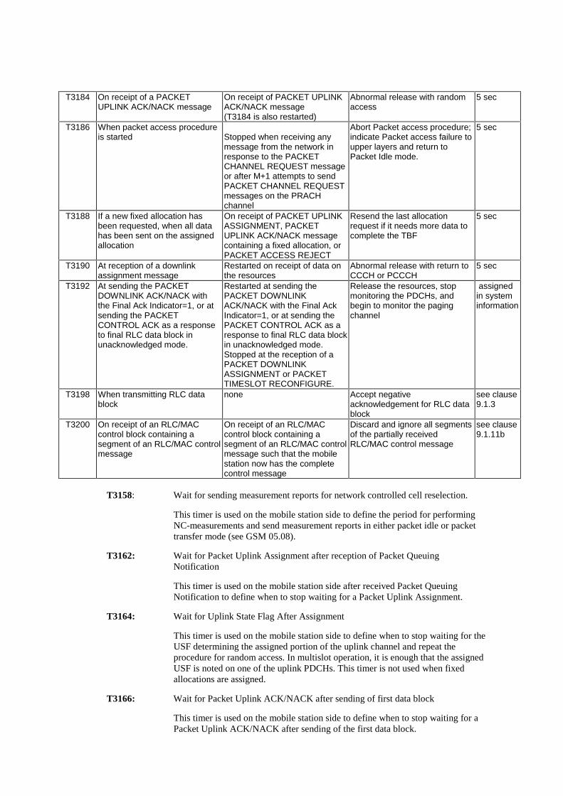
T3158: Wait for sending measurement reports for network controlled cell reselection.
This timer is used on the mobile station side to define the period for performingNC-measurements and send measurement reports in either packet idle or packettransfer mode (see GSM 05.08).
T3162: Wait for Packet Uplink Assignment after reception of Packet QueuingNotification
This timer is used on the mobile station side after received Packet QueuingNotification to define when to stop waiting for a Packet Uplink Assignment.
T3164: Wait for Uplink State Flag After Assignment
This timer is used on the mobile station side to define when to stop waiting for theUSF determining the assigned portion of the uplink channel and repeat theprocedure for random access. In multislot operation, it is enough that the assignedUSF is noted on one of the uplink PDCHs. This timer is not used when fixedallocations are assigned.
T3166: Wait for Packet Uplink ACK/NACK after sending of first data block
This timer is used on the mobile station side to define when to stop waiting for aPacket Uplink ACK/NACK after sending of the first data block.

T3168: Wait for Packet Uplink Assignment message
This timer is used on the mobile station side to define when to stop waiting for aPacket Uplink Assignment message after sending of a Packet Resource requestmessage.
T3170: Wait for Packet Uplink Assignment after having done (M+1) Packet ChannelRequests or after reception of a PACKET ACCESS REJECT message.
This timer is used on the mobile station side when having made M + 1 attempts tosend a Packet Channel Request or after reception of a PACKET ACCESSREJECT message. At expiry of timer T3170, the mobile station shall abort thepacket access procedure, indicate a packet access failure to upper layer and returnto packet idle mode.
The value of this timer is equal to the time taken by T+2S TDMA frames. T and Sare defined in subclause 7.1.2.1.1.
T3172: Prohibit packet access in the cell after Packet Access Reject message has beenreceived.
This timer is used on the mobile station side on receipt of a Packet Access Rejectmessage corresponding to one of the mobile station’s 3 last Packet ChannelRequest messages.
After T3172 expiry packet Access is no longer prohibited in the cell but noChannel Request message shall be sent as a response to a page until a PagingRequest message for the mobile station is received.
T3174: Wait for response on new cell after Packet Cell Change Order .
This timer is used on the mobile station side on receipt of a PACKET CELLCHANGE ORDER message. The timer is stopped upon successful access on thenew cell. On expiry, the mobile station returns to the old cell and send PACKETCELL CHANGE FAILURE message.
T3176: Stop Cell Change failure procedure .
This timer started when T3174 expires. The timer is stopped upon transmission ofthe PACKET CELL CHANGE FAILURE message. On expiry, the mobile stationstops attempting to send the PACKET CELL CHANGE FAILURE message.
T3178: Wait for sending extended measurement reports.
This timer is used on the mobile station side to define the period for performingextended measurements and send extended measurement reports in packet idlemode (see GSM 05.08).
T3180: Wait for Uplink State Flag After Data Block
This timer is used on the mobile station side to define when to stop waiting for theUSF determining the assigned portion of the uplink channel after the perviousRLC/MAC block is sent. In multislot operation, it is enough that the assignedUSF is noted on one of the uplink PDCHs. If expired, the mobile station repeatsthe procedure for random access. This timer does not apply to fixed allocationtransfers.
T3182: Wait for Acknowledgement
This timer is used on the mobile station side to define when to stop waiting fortemporary Packet Uplink Ack/Nack after the last RLC data block has been sentfor the current send window or for the entire Temporary Block Flow.

T3184: No Ack/Nack Received
This timer is used on the mobile station side to decide when to stop waiting for aPacket Uplink Ack/Nack. (This timer does not apply to mobiles performing adynamic allocation transfer).
T3186: Supervision of the random access procedure
This timer is used on the mobile station side to define the maximum allowed timeto repeat the sending of all PACKET CHANNEL REQUEST messages. At expiryof timer T3186, the Packet Uplink establishment procedure is aborted.
T3188: Allocation Exhausted
This timer is used on the mobile station side to decide when to stop waiting toreceive additional resources from the network. (This timer does not apply to amobile performing a dynamic allocation transfer).
T3190: Wait for Valid Downlink Data Received from the Network
This timer is used on the mobile station side to stop waiting for the valid datafrom the network side either following the initial Packet Downlink Assignment orafter some previous downlink RLC/MAC block.
T3192: Wait for release of the TBF after reception of the final block
This timer is used on the mobile station side when the mobile station has receivedall of the RLC data blocks. When timer T3192 expires the mobile station shallrelease the resources associated with the TBF (e.g. TFI) and begin to monitor itspaging channel.
T3198: RLC timer
T3198 is an array of 64 timers used by the mobile station to control when it willaccept a negative acknowledgement for an RLC data block.
T3200 RLC/MAC control message reassembly guard
T3200 is used by the mobile station to control when it will discard segments of apartially received RLC/MAC control message. The mobile station shall have oneinstance of timer T3200 for each segmented RLC/MAC control message that themobile station is capable of receiving in parallel.
SMG2 #35Schaumburg, Illinois, U.S.A., 3-7 April 2000
Document 2-00-846Agenda Item 7.1.5.1
CHANGE REQUEST Please see embedded help file at the bottom of thispage for instructions on how to fill in this form correctly.
Current Version: 7.3.004.60 CR A839GSM (AA.BB) or 3G (AA.BBB) specification number ↑ ↑ CR number as allocated by MCC support team
For submission to: SMG #32 for approval X strategic (for SMGlist expected approval meeting # here
↑for information non-strategic X use only)
Form: CR cover sheet, version 2 for 3GPP and SMG The latest version of this form is available from: ftp://ftp.3gpp.org/Information/CR-Form-v2.doc
Proposed change affects: (U)SIM ME X UTRAN / Radio X Core Network(at least one should be marked with an X)
Source: Motorola, Inc. Date: 5 April 2000
Subject: Correction to timer T3174 value
Work item: GPRS
Category: F Correction X Release: Phase 2A Corresponds to a correction in an earlier release Release 96
(only one category B Addition of feature Release 97shall be marked C Functional modification of feature Release 98 Xwith an X) D Editorial modification Release 99
Release 00
Reason forchange:
Value of timer T3174 is logically inconsistent with the amount of time required forprocessing actions to be performed between the time it is started and the time it expires.
The intention of T3174 is to protect against the failure of network controlled (NC) cellreselection. It is started upon the receipt of a PACKET CELL CHANGE ORDER message, andstopped upon the receipt of a CHANNEL REQUEST or a PACKET CHANNEL REQUEST inthe new cell. If T3174 expires in the process of selecting a new cell, then the mobile stationreturns to the old cell and sends a PACKET CELL CHANGE FAILURE.Problem: Once the mobile station has received the PACKET CELL CHANGE ORDER, theworst-case amount of time required for processing System Information (SI) and Packet SystemInformation (PSI) messages may exceed the current 5 second value of T3174.For example:- Reading of SI-13 (to find PBCCH) : maximum approximately 3 seconds based on message
periodicity- Reading of PSI-1, PSI-2 and PSI-3 (on PBCCH) : maximum approximately 16 * a 52-
frame multiframe period = 16 * 240 ms = 3.85 seconds.Total = 3 + 3.85 = 6.85 seconds + any additional time required for signalling overhead.In such cases, this would cause the mobile station to unnecessarily revert back to its previouscell, which is not what is intended by the specification.Solution: It is therefore proposed that timer T3174 be increased to an appropriate value. Thisproblem was acknowledged and discussed with several manufacturers, including Ericsson,Matsushita and Nokia. All agree that a reasonable value for T3174 would be 15 seconds.
Clauses affected: 13.1 Timers on the Mobile Station side
Other specs Other 3G core specifications → List of CRs:affected: Other GSM core
specifications→ List of CRs:

MS test specifications → List of CRs:BSS test specifications → List of CRs:O&M specifications → List of CRs:
Othercomments:
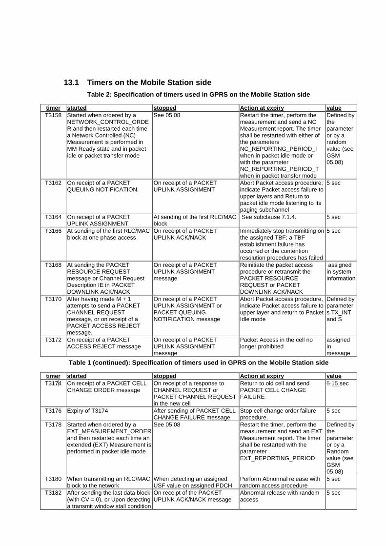
13.1 Timers on the Mobile Station side
Table 2: Specification of timers used in GPRS on the Mobile Station side
timer started stopped Action at expiry valueT3158 Started when ordered by a
NETWORK_CONTROL_ORDER and then restarted each timea Network Controlled (NC)Measurement is performed inMM Ready state and in packetidle or packet transfer mode
See 05.08 Restart the timer, perform themeasurement and send a NCMeasurement report. The timershall be restarted with either ofthe parametersNC_REPORTING_PERIOD_Iwhen in packet idle mode orwith the parameterNC_REPORTING_PERIOD_Twhen in packet transfer mode
Defined bytheparameteror by arandomvalue (seeGSM05.08)
T3162 On receipt of a PACKETQUEUING NOTIFICATION.
On receipt of a PACKETUPLINK ASSIGNMENT
Abort Packet access procedure;indicate Packet access failure toupper layers and Return topacket idle mode listening to itspaging subchannel
5 sec
T3164 On receipt of a PACKETUPLINK ASSIGNMENT
At sending of the first RLC/MACblock
See subclause 7.1.4. 5 sec
T3166 At sending of the first RLC/MACblock at one phase access
On receipt of a PACKETUPLINK ACK/NACK
Immediately stop transmitting onthe assigned TBF; a TBFestablishment failure hasoccurred or the contentionresolution procedures has failed
5 sec
T3168 At sending the PACKETRESOURCE REQUESTmessage or Channel RequestDescription IE in PACKETDOWNLINK ACK/NACK
On receipt of a PACKETUPLINK ASSIGNMENTmessage
Reinitiate the packet accessprocedure or retransmit thePACKET RESOURCEREQUEST or PACKETDOWNLINK ACK/NACK
assignedin systeminformation
T3170 After having made M + 1attempts to send a PACKETCHANNEL REQUESTmessage, or on receipt of aPACKET ACCESS REJECTmessage.
On receipt of a PACKETUPLINK ASSIGNMENT orPACKET QUEUINGNOTIFICATION message
Abort Packet access procedure,indicate Packet access failure toupper layer and return to PacketIdle mode
Defined byparameters TX_INTand S
T3172 On receipt of a PACKETACCESS REJECT message
On receipt of a PACKETUPLINK ASSIGNMENTmessage
Packet Access in the cell nolonger prohibited
assignedinmessage
Table 1 (continued): Specification of timers used in GPRS on the Mobile Station side
timer started stopped Action at expiry valueT3174 On receipt of a PACKET CELL
CHANGE ORDER messageOn receipt of a response toCHANNEL REQUEST orPACKET CHANNEL REQUESTin the new cell
Return to old cell and sendPACKET CELL CHANGEFAILURE
5 15 sec
T3176 Expiry of T3174 After sending of PACKET CELLCHANGE FAILURE message
Stop cell change order failureprocedure.
5 sec
T3178 Started when ordered by aEXT_MEASUREMENT_ORDERand then restarted each time anextended (EXT) Measurement isperformed in packet idle mode
See 05.08 Restart the timer, perform themeasurement and send an EXTMeasurement report. The timershall be restarted with theparameterEXT_REPORTING_PERIOD
Defined bytheparameteror by aRandomvalue (seeGSM05.08)
T3180 When transmitting an RLC/MACblock to the network
When detecting an assignedUSF value on assigned PDCH
Perform Abnormal release withrandom access procedure
5 sec
T3182 After sending the last data block(with CV = 0), or Upon detectinga transmit window stall condition
On receipt of the PACKETUPLINK ACK/NACK message
Abnormal release with randomaccess
5 sec

T3184 On receipt of a PACKETUPLINK ACK/NACK message
On receipt of PACKET UPLINKACK/NACK message(T3184 is also restarted)
Abnormal release with randomaccess
5 sec
T3186 When packet access procedureis started Stopped when receiving any
message from the network inresponse to the PACKETCHANNEL REQUEST messageor after M+1 attempts to sendPACKET CHANNEL REQUESTmessages on the PRACHchannel
Abort Packet access procedure;indicate Packet access failure toupper layers and return toPacket Idle mode.
5 sec
T3188 If a new fixed allocation hasbeen requested, when all datahas been sent on the assignedallocation
On receipt of PACKET UPLINKASSIGNMENT, PACKETUPLINK ACK/NACK messagecontaining a fixed allocation, orPACKET ACCESS REJECT
Resend the last allocationrequest if it needs more data tocomplete the TBF
5 sec
T3190 At reception of a downlinkassignment message
Restarted on receipt of data onthe resources
Abnormal release with return toCCCH or PCCCH
5 sec
T3192 At sending the PACKETDOWNLINK ACK/NACK withthe Final Ack Indicator=1, or atsending the PACKETCONTROL ACK as a responseto final RLC data block inunacknowledged mode.
Restarted at sending thePACKET DOWNLINKACK/NACK with the Final AckIndicator=1, or at sending thePACKET CONTROL ACK as aresponse to final RLC data blockin unacknowledged mode.Stopped at the reception of aPACKET DOWNLINKASSIGNMENT or PACKETTIMESLOT RECONFIGURE.
Release the resources, stopmonitoring the PDCHs, andbegin to monitor the pagingchannel
assignedin systeminformation
T3198 When transmitting RLC datablock
none Accept negativeacknowledgement for RLC datablock
see clause9.1.3
T3200 On receipt of an RLC/MACcontrol block containing asegment of an RLC/MAC controlmessage
On receipt of an RLC/MACcontrol block containing asegment of an RLC/MAC controlmessage such that the mobilestation now has the completecontrol message
Discard and ignore all segmentsof the partially receivedRLC/MAC control message
see clause9.1.11b
T3158: Wait for sending measurement reports for network controlled cell reselection.
This timer is used on the mobile station side to define the period for performingNC-measurements and send measurement reports in either packet idle or packettransfer mode (see GSM 05.08).
T3162: Wait for Packet Uplink Assignment after reception of Packet QueuingNotification
This timer is used on the mobile station side after received Packet QueuingNotification to define when to stop waiting for a Packet Uplink Assignment.
T3164: Wait for Uplink State Flag After Assignment
This timer is used on the mobile station side to define when to stop waiting for theUSF determining the assigned portion of the uplink channel and repeat theprocedure for random access. In multislot operation, it is enough that the assignedUSF is noted on one of the uplink PDCHs. This timer is not used when fixedallocations are assigned.
T3166: Wait for Packet Uplink ACK/NACK after sending of first data block
This timer is used on the mobile station side to define when to stop waiting for aPacket Uplink ACK/NACK after sending of the first data block.
T3168: Wait for Packet Uplink Assignment message
This timer is used on the mobile station side to define when to stop waiting for aPacket Uplink Assignment message after sending of a Packet Resource requestmessage.
T3170: Wait for Packet Uplink Assignment after having done (M+1) Packet ChannelRequests or after reception of a PACKET ACCESS REJECT message.
This timer is used on the mobile station side when having made M + 1 attempts tosend a Packet Channel Request or after reception of a PACKET ACCESSREJECT message. At expiry of timer T3170, the mobile station shall abort thepacket access procedure, indicate a packet access failure to upper layer and returnto packet idle mode.
The value of this timer is equal to the time taken by T+2S TDMA frames. T and Sare defined in subclause 7.1.2.1.1.
T3172: Prohibit packet access in the cell after Packet Access Reject message has beenreceived.
This timer is used on the mobile station side on receipt of a Packet Access Rejectmessage corresponding to one of the mobile station’s 3 last Packet ChannelRequest messages.
After T3172 expiry packet Access is no longer prohibited in the cell but noChannel Request message shall be sent as a response to a page until a PagingRequest message for the mobile station is received.
T3174: Wait for response on new cell after Packet Cell Change Order .
This timer is used on the mobile station side on receipt of a PACKET CELLCHANGE ORDER message. The timer is stopped upon successful access on thenew cell. On expiry, the mobile station returns to the old cell and send PACKETCELL CHANGE FAILURE message.
T3176: Stop Cell Change failure procedure .
This timer started when T3174 expires. The timer is stopped upon transmission ofthe PACKET CELL CHANGE FAILURE message. On expiry, the mobile stationstops attempting to send the PACKET CELL CHANGE FAILURE message.
T3178: Wait for sending extended measurement reports.
This timer is used on the mobile station side to define the period for performingextended measurements and send extended measurement reports in packet idlemode (see GSM 05.08).
T3180: Wait for Uplink State Flag After Data Block
This timer is used on the mobile station side to define when to stop waiting for theUSF determining the assigned portion of the uplink channel after the perviousRLC/MAC block is sent. In multislot operation, it is enough that the assignedUSF is noted on one of the uplink PDCHs. If expired, the mobile station repeatsthe procedure for random access. This timer does not apply to fixed allocationtransfers.
T3182: Wait for Acknowledgement
This timer is used on the mobile station side to define when to stop waiting fortemporary Packet Uplink Ack/Nack after the last RLC data block has been sentfor the current send window or for the entire Temporary Block Flow.
T3184: No Ack/Nack Received
This timer is used on the mobile station side to decide when to stop waiting for aPacket Uplink Ack/Nack. (This timer does not apply to mobiles performing adynamic allocation transfer).
T3186: Supervision of the random access procedure
This timer is used on the mobile station side to define the maximum allowed timeto repeat the sending of all PACKET CHANNEL REQUEST messages. At expiryof timer T3186, the Packet Uplink establishment procedure is aborted.
T3188: Allocation Exhausted
This timer is used on the mobile station side to decide when to stop waiting toreceive additional resources from the network. (This timer does not apply to amobile performing a dynamic allocation transfer).
T3190: Wait for Valid Downlink Data Received from the Network
This timer is used on the mobile station side to stop waiting for the valid datafrom the network side either following the initial Packet Downlink Assignment orafter some previous downlink RLC/MAC block.
T3192: Wait for release of the TBF after reception of the final block
This timer is used on the mobile station side when the mobile station has receivedall of the RLC data blocks. When timer T3192 expires the mobile station shallrelease the resources associated with the TBF (e.g. TFI) and begin to monitor itspaging channel.
T3198: RLC timer
T3198 is an array of 64 timers used by the mobile station to control when it willaccept a negative acknowledgement for an RLC data block.
T3200 RLC/MAC control message reassembly guard
T3200 is used by the mobile station to control when it will discard segments of apartially received RLC/MAC control message. The mobile station shall have oneinstance of timer T3200 for each segmented RLC/MAC control message that themobile station is capable of receiving in parallel.
ETSI SMG2 meeting #35 Document 895/00Schaumburg, USA3 – 7 April 2000
Agenda item 7.1.5.1e.g. for 3GPP use the format TP-99xxx
or for SMG, use the format P-99-xxx
CHANGE REQUEST Please see embedded help file at the bottom of thispage for instructions on how to fill in this form correctly.
Current Version: 8.3.004.18 CR A098r2GSM (AA.BB) or 3G (AA.BBB) specification number ↑ ↑ CR number as allocated by MCC support team
For submission to: SMG #31bis for approval X strategic (for SMGlist expected approval meeting # here ↑ for information non-strategic use only)
Form: CR cover sheet, version 2 for 3GPP and SMG The latest version of this form is available from: ftp://ftp.3gpp.org/Information/CR-Form-v2.doc
Proposed change affects: (U)SIM ME X UTRAN / Radio X Core Network(at least one should be marked with an X)
Source: Vodafone AirTouch Date: 5 April 2000
Subject: DTM: definition of new procedures while in dedicated mode
Work item: BSS co-ordination of Radio Resources allocation for class A GPRS services - GSMRadio Access (R99)
Category: F Correction Release: Phase 2A Corresponds to a correction in an earlier release Release 96
(only one category B Addition of feature X Release 97shall be marked C Functional modification of feature Release 98with an X) D Editorial modification Release 99 X
Release 00
Reason forchange:
The specification of dual transfer mode requires changes and additions to the currentprocedures describing the behaviour of the new mobile stations in order to establish,maintain and release a packet resource while in dedicated mode.
Clauses affected: 3.1.2.7, 3.4.22, 3.4.23, 3.4.24, 11.1
Other specs Other 3G core specifications → List of CRs:affected: Other GSM core specifications → List of CRs:
MS test specifications → List of CRs:BSS test specifications → List of CRs:O&M specifications → List of CRs:
Othercomments:
The structure of the sub-clauses modified in this CR is:3.1.2 Services provided to upper layers ..................................................................................3.1.2.1 Idle mode ..................................................................................................................3.1.2.2 Dedicated mode ........................................................................................................3.1.2.3 Group receive mode .................................................................................................3.1.2.4 Group transmit mode ................................................................................................3.1.2.5 Packet idle mode ......................................................................................................3.1.2.6 Packet transfer mode ................................................................................................3.1.2.7 Dual transfer mode (DTM) .......................................................................................3.4.22 RR procedures related to packet resource establishment while in dedicated
mode ...............................................................................................................................3.4.22.1 Packet request procedure while in dedicated mode ..................................................3.4.22.1.1 Entering the dual transfer mode ..........................................................................
3.4.22.1.1.1 Permission to access the network ..................................................................3.4.22.1.1.2 Initiation of establishment of the packet request procedure ..........................3.4.22.1.1.3 Answer from the network ..............................................................................3.4.22.1.1.3.1 Packet assignment ...................................................................................3.4.22.1.1.3.2 RR reallocation only ................................................................................3.4.22.1.1.3.3 Packet request rejection ...........................................................................3.4.22.1.1.4 Packet request completion .............................................................................3.4.22.1.1.5 Abnormal cases .............................................................................................3.4.22.2 Packet notification procedure in dedicated mode .....................................................3.4.22.2.1 Packet notification initiation by the network ......................................................3.4.22.2.2 Packet notification response ...............................................................................3.4.22.3 Packet downlink assignment in dedicated mode ......................................................3.4.22.3.1 Initiation of the packet downlink assignment procedure in dedicated
mode ...................................................................................................................3.4.22.3.2 Packet downlink assignment completion ............................................................3.4.22.3.3 Abnormal cases ...................................................................................................3.4.22.4 Modification of packet resources while in DTM ......................................................3.4.23 RR procedures related to packet resource maintenance while in dual transfer
mode ...............................................................................................................................3.4.24 RR procedures related to packet resource release while in dual transfer mode .............11.1 Timers and counters for radio resource management ..........................................................11.1.1 Timers on the mobile station side ..................................................................................11.1.2 Timers on the network side ............................................................................................11.1.3 Other parameters ............................................................................................................3.1.2 Services provided to upper layers 33.1.2.1 Idle mode 33.1.2.2 Dedicated mode 33.1.2.3 Group receive mode 33.1.2.4 Group transmit mode 33.1.2.5 Packet idle mode 43.1.2.6 Packet transfer mode 43.1.2.7 Dual transfer mode (DTM) 43.4.22 RR procedures related to packet resource establishment while in dedicated
mode 43.4.22.1 Packet request procedure while in dedicated mode 53.4.22.1.1 Entering the dual transfer mode 53.4.22.1.1.1 Permission to access the network 53.4.22.1.1.2 Initiation of establishment of the packet request procedure 53.4.22.1.1.3 Answer from the network 53.4.22.1.1.3.1 Packet assignment 53.4.22.1.1.3.2 RR reallocation only 63.4.22.1.1.3.3 Packet request rejection 63.4.22.1.1.4 Packet request completion 63.4.22.1.1.5 Abnormal cases 73.4.22.1.2 Packet resource re-establishment 73.4.22.2 Packet notification procedure in dedicated mode 73.4.22.2.1 Packet notification initiation by the network 73.4.22.2.2 Packet notification response 73.4.22.3 Packet downlink assignment in dedicated mode 83.4.22.3.1 Initiation of the packet downlink assignment procedure in dedicated
mode 83.4.22.3.2 Packet downlink assignment completion 83.4.22.3.3 Abnormal cases 83.4.22.4 Modification of packet resources while in DTM 93.4.23 RR procedures related to packet resource maintenance while in dual transfer
mode 93.4.24 RR procedures related to packet resource release while in dual transfer mode 911.1 Timers and counters for radio resource management 911.1.1 Timers on the mobile station side 911.1.2 Timers on the network side 12
11.1.3 Other parameters 13
help.doc
<--------- double-click here for help and instructions on how to create a CR.
3.1.2 Services provided toupper layersA RR connection is a physical connection used by the two peer entities to support the upper layers’exchange of information flows.3.1.2.1 Idle modeIn idle mode no RR connection exists.The RR procedures include (on the mobile station side) those for automatic cell selection/reselection.The RR entity indicates to upper layers the unavailability of a BCCH/CCCH and the cell change whendecided by the RR entity. Upper layers are advised of the BCCH broadcast information when a newcell has been selected, or when a relevant part of this information changes.In Idle mode, upper layers can require the establishment of an RR connection.3.1.2.2 Dedicated modeIn dedicated mode, the RR connection is a physical point-to-point bi-directional connection, andincludes a SAPI 0 data link connection operating in multiframe mode on the main DCCH. If dedicatedmode is established, RR procedures provide the following services:
- establishment/release of multiframe mode on data link layer connections other than SAPI 0, onthe main DCCH or on the SACCH associated with the channel carrying the main signalling link;
- transfer of messages on any data link layer connection;
- indication of temporary unavailability of transmission (suspension, resuming);
- indication of loss of RR connection;
- automatic cell reselection and handover to maintain the RR connection;
- setting/change of the transmission mode on the physical channels, including change of type ofchannel, change of the coding/decoding/transcoding mode and setting of ciphering;
- allocation/release of an additional channel (for the TCH/H + TCH/H configuration);
- allocation/release of additional channels for multislot operation;
- release of an RR connection.
3.1.2.3 Group receive modeOnly applicable for mobile stations supporting VGCS listening or VBS listening.In this mode, the RR procedures on the mobile station side provide the services:
- local connection to the voice broadcast channel or voice group call channel;
- reception of messages in unacknowledged mode;
- automatic cell reselection for the mobile station in Group receive mode;
- local disconnection from the received voice group call or broadcast call channels.
For mobile stations supporting both VGCS listening and VGCS transmit, in addition, the RRprocedures on the mobile station side provide the service:
- uplink access procedures to establish the RR connection.
3.1.2.4 Group transmit modeOnly applicable for mobile stations supporting VGCS talking.In group transmit mode, the RR connection is a physical point-to-point bi-directional connection, andincludes a SAPI 0 data link connection operating in multiframe mode on the main DCCH. If the grouptransmit mode is established, RR procedures provide the following services:
- transfer of messages on the SAPI 0 of the data link layer connection;
- indication of loss of RR connection;
- automatic cell reselection and handover to maintain the RR connection;
- setting of the transmission mode on the physical channels, change of type of channel and settingof ciphering;
- release of the RR connection.
3.1.2.5 Packet idle modeOnly applicable for mobile stations supporting GPRS.In packet idle mode, no temporary block flow exists (see GSM 04.60). Upper layers may require thetransfer of a LLC PDU, which implicitly triggers the establishment of a temporary block flow.3.1.2.6 Packet transfer modeOnly applicable for mobile stations supporting GPRS.In packet transfer mode, the mobile station is allocated radio resource providing a temporary blockflow on one or more packet data physical channels. The RR sublayer provides the following services,see also GSM 04.60:
- transfer of LLC PDUs in acknowledged mode;
- transfer of LLC PDUs in unacknowledged mode.
Depending on the GPRS mode of operation (class A or B), the mobile station may leave both packetidle mode and packet transfer mode before entering dedicated mode, group receive mode or grouptransmit mode.Cell reselection in packet idle and packet transfer modes is specified in GSM 05.08. The RR entity onthe mobile station side indicates to the upper layers the availability of a cell and a cell change whendecided by the RR sublayer. Upper layers are advised of system information broadcast in the cell whena new cell has been selected, or when a relevant part of this information changes.3.1.2.7 Dual transfer mode (DTM)Only applicable for mobile stations supporting GPRS class A mode of operation, provided that radioresource allocation co-ordination is performed by the network. This feature is optional for the mobilestation and the network.In dual transfer mode, the mobile station is simultaneously in dedicated mode and in packet transfermode.This feature is optional for the mobile station and the network. It is only applicable for a mobile stationsupporting GPRS. Dual transfer mode is a subset of class A mode of operation, only possible if there isradio resource allocation co-ordination in the network.
Next modified section
3.4.22 RR proceduresrelated to packet resource establishment while in dedicated modeThe establishment of a packet resource is supported by procedures on the main DCCH when the mobilestation is in dedicated mode. The procedures are only applicable to a mobile station supporting bothGPRS and DTM. The procedures are optional for the network.These procedures constitute a complement to the corresponding procedures for temporary block flowestablishment using CCCH or PCCCH while in idle mode defined in GSM 04.18 and 04.60,respectively.The packet request procedure is initiated by the MS and it is described in clause 3.4.22.1. The packetnotification procedure is initiated by the network and it is described in 3.4.22.2. The packet downlinkassignment is initiated by the network and it is described in clause 3.4.22.3.3.4.22.1 Packet request procedure while in dedicated modeThe packet request procedure using the main DCCH may be used to establish a packet resource tosupport the transfer of LLC PDUs in the direction from the mobile station to the network.
3.4.22.1.1 Entering the dual transfer mode
While in dedicated mode, the establishment of an uplink packet resource may be initiated by the RRentity of the mobile station using the packet request procedure. The procedure is triggered by a requestfrom upper layers to transfer an LLC PDU; see TS 24.007. The request from upper layers specifies:
- TLLI
- radio priority,
- RLC mode associated with the packet transfer,
- LLC frame type,
- establishment cause and
- QoS information for the requested packet session.
Upon such a request, the RR entity of the mobile station- if access to the network is allowed (section 3.4.22.1.1.1), it initiates the packet request procedure
as defined in section 3.4.22.1.1.2;
- otherwise, it rejects the request.
If the request from upper layers indicates any signalling procedure and the acknowledged RLC modeshall be used.
3.4.22.1.1.1 Permission to access the network
Access to the network is allowed:- if dual transfer mode is supported in the cell, as indicated by the DTM_CELL_SUPPORT field
included in SI messages.
NOTE: belonging to an authorised access class or special class, radio priority level and LSApermission are not considered since they only apply to a mobile station in idle mode.
3.4.22.1.1.2 Initiation of establishment of the packet request procedure
The mobile station initiates the establishment the packet resource by sending a DTM REQUESTmessage on the main DCCH.The DTM REQUEST message contains:
- TLLI;
- MS GPRS Radio Access Capabilities;
- Channel Request Description;
Having sent the DTM REQUEST message, the mobile station starts timer T3148.
3.4.22.1.1.3 Answer from the network
3.4.22.1.1.3.1 Packet assignment
On receipt of a DTM REQUEST message the network may allocate an uplink packet resource. Thepacket uplink resource is assigned to the mobile station in one of the DTM assignment messages:
- DTM ASSIGNMENT COMMAND,- PACKET ASSIGNMENT COMMAND or- MAIN DCCH ASSIGNMENT COMMAND.
These messages are sent in acknowledged mode on the main DCCH. If frequency hopping is applied,the mobile station shall use the cell allocation defined for the cell to decode the mobile allocation.The allocation of the uplink packet resource may imply the reallocation of the resource for the RRconnection. In this case, the DTM ASSIGNMENT COMMAND message is used and the timer T3107is started on the network side. The DTM ASSIGNMENT COMMAND message shall not be used tochange to a dependent configuration.The PACKET ASSIGNMENT COMMAND message is only used when the packet resource is a PDCHand no reallocation of the CSRR connection is needed.The MAIN DCCH ASSIGNMENT COMMAND message is only sent to allocate the main DCCH asthe requested packet resource. This messages indicates the maximum number of octets in length thatfurther LLC frames can be in order to be able to use the main DCCH without a request. A new packetrequest procedure shall be initiated when the length of the LLC frame is above this value or when thereis a change in any of the other parameters sent in the DTM REQUEST message.On receipt of a:
- DTM ASSIGNMENT COMMAND message,- PACKET ASSIGNMENT COMMAND message or- MAIN DCCH ASSIGNMENT COMMAND message,
the mobile station shall stop T3148 (if running), stopand T3142 (if running), and switch to the assignedresources. The mobile station has then entered the dual transfer mode.
3.4.22.1.1.3.2 RR reallocation only
During the packet request procedure the network may answer withsend a- HANDOVER COMMAND message or- ASSIGNMENT COMMAND message,.
upon whose receipt, the timers T3148 and T3142 are stopped (if running), any allocated packetresource is released and the handover or assignment procedure is performed.
3.4.22.1.1.3.3 Packet request rejection
If the network cannot allocated the requested packet resource it may send the mobile station a DTMREJECT message in acknowledged mode on the main DCCH. This message may contains a wait time(“wait indication” information element). If the wait indication IE is not present, indefinite waiting timeapplies. The mobile station is not allowed to make a new attempt for packet request during the waitingtime.The DTM REJECT message also contains an indication of whether the waiting time applies after asuccessful handover procedure or a re-attempt of packet resource establishment can be madeimmediately after it. The waiting time shall always end when the CS connection is releasedMS entersthe idle mode.On receipt of the DTM REJECT message, the mobile station stops T3148 if it has not already beenstopped, notifies upper layers of a packet resource establishment failure. If the waiting indication IE ispresent, the mobile station and starts timer T3142 with the indicated value.During the validity of the waiting time (i.e. T3142 or indefinite), additional DTM REJECT messagesare ignored, but any DTM assignment message make the mobile station follow the procedure in section3.4.22.1.1.3.1. If no such assignment message is received, then, after the validity of the waiting time,the mobile station returns dedicated mode and upper layers are notified of a packet resourceestablishment failure.may re-attempt the packet request procedure.
3.4.22.1.1.4 Packet request completion
The completion of the packet request procedure depends on the actual assignment message used by thenetwork:- when the network sends a DTM ASSIGNMENT COMMAND message (i.e. reallocation of the CS
resource is required), after the main signalling link is successfully established, the mobile stationreturns an ASSIGNMENT COMPLETE message, specifying cause “"normal event"”, to thenetwork on the main DCCH. The packet request procedure is completed, for the mobile station,when the ASSIGNMENT COMPLETE message is sent and, for the network, when it is received.;tThe network then stops timer T3107.
- when the network sends a PACKET ASSIGNMENT COMMAND or a MAIN DCCHASSIGNMENT COMMAND message, the packet request procedure is completed, for thenetwork, when assignment message is sent and, for the mobile station, when it is received.
When the packet request procedure is completed, the mobile station has entered the dual transfer mode.
3.4.22.1.1.5 Abnormal cases
If a failure occurs on the mobile station side before the packet request procedure is completed, all theallocated packet resources are released, the mobile station returns to dedicated mode and upper layersare notified (packet resource establishment failure).
-If a DTM assignment message indicates packet resources in a non-supported frequency band, themobile station sends an ASSIGNMENT FAILURE message on the main DCCH.
-If the information available in the mobile station after the reception of a DTM assignment messagedoes not satisfactorily define uplink packet resources, a packet resource establishment failurehas occurred and the mobile station sends a DTM ASSIGNMENT FAILURE message on theold main DCCH.
If the network commands the mobile station to reallocate the CS resource and the establishment ofthe main DCCH fails, the mobile station shall revert to the old channel and send anASSIGNMENT FAILURE message on the old main DCCH.
If the mobile allocation indexes frequencies in more than one frequency band then a packet resourceestablishment failure has occurred and the mobile station sends a DTM ASSIGNMENTFAILURE message on the main DCCH.
If a DTM assignment message assigns resources not compliant with the multislot capabilities of themobile station, a packet resource establishment failure has occurred and the mobile station sendsa DTM ASSIGNMENT FAILURE message on the old main DCCH.
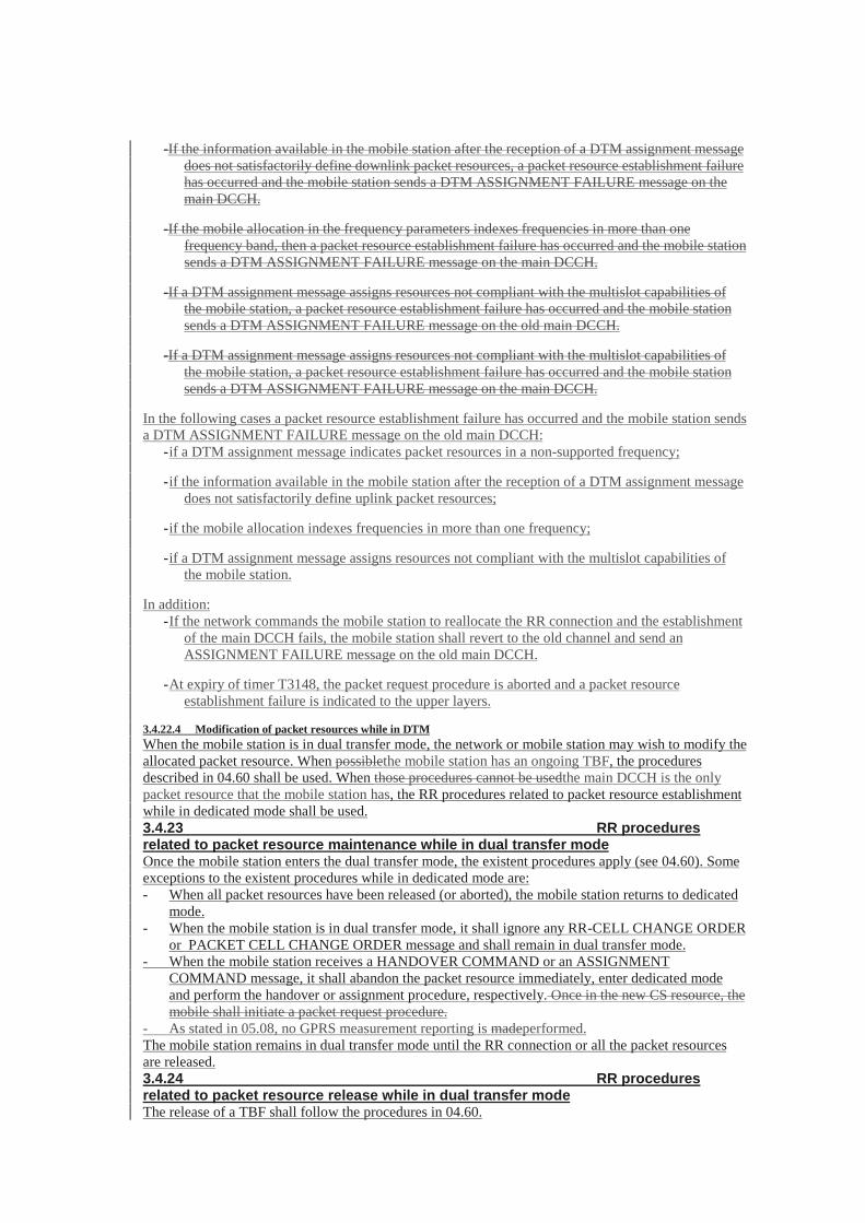
In the following cases a packet resource establishment failure has occurred and the mobile station sendsa DTM ASSIGNMENT FAILURE message on the old main DCCH:
- if a DTM assignment message indicates packet resources in a non-supported frequency;
- if the information available in the mobile station after the reception of a DTM assignment messagedoes not satisfactorily define uplink packet resources;
- if the mobile allocation indexes frequencies in more than one frequency;
- if a DTM assignment message assigns resources not compliant with the multislot capabilities ofthe mobile station.
In addition:- If the network commands the mobile station to reallocate the RR connection and the establishment
of the main DCCH fails, the mobile station shall revert to the old channel and send anASSIGNMENT FAILURE message on the old main DCCH.
- At expiry of timer T3148, the packet request procedure is aborted and a packet resourceestablishment failure is indicated to the upper layers.
3.4.22.1.2 Packet resource re-establishment
The packet resources of a mobile station in dual transfer mode can be temporarily abandoned in orderto establish the RR connection (e.g. during the handover procedure).When a DCCH has been established, the mobile station shall initiate the establishment of a packetresource while in dedicated mode as described in 3.4.22.1.1. The DTM REQUEST message shallindicate packet resource re-establishment (uplink, downlink or both) as the cause of the packet requestinitiation.3.4.22.2 Packet notification procedure in dedicated modeThe packet notification procedure in dedicated mode is used to trigger a ‘Paging Response’ from themobile station. This procedure is always initiated by the network.This procedure is always initiated by the network. It is only applicable to a mobile station in dedicatedmode, in the STANDBY state and with no packet resources allocated. If the mobile station already haspacket resources allocated, the establishment of the downlink packet resource is performed on thePACCH; see 04.60. If the mobile station is in the READY state, the packet downlink assignmentprocedure described in 3.4.22.3 applies.The packet notification procedure is initiated by the RR entity of the network side. It is triggered by apage request from the GMM sublayer, see TS 24.007.
3.4.22.2.1 Packet notification initiation by the network
The network initiates the packet notification procedure by sending the mobile station a PACKETNOTIFICATION message on the main DCCH.The network shall not send the PACKET NOTIFICATION message to a mobile station that does notsupport dual transfer mode operation. If a mobile station not supporting dual transfer mode receivesthis message, it shall ignore it and remain in dedicated mode.
3.4.22.2.2 Packet notification response
Upon receipt of the PACKET NOTIFICATION message, the RR sublayer of the mobile stationindicates the receipt of a packet paging request to the GMM sublayer; see TS 24.007.
3.4.22.3 Packet downlink assignment in dedicated modeThe packet downlink assignment procedure in dedicated mode may be used to establish a packetresource to support the transfer of LLC PDUs in the direction from the network to the mobile station.This procedure is only applicable to a mobile station in dedicated mode, in the READY state and withno packet resources TBF allocated. If the mobile station already has packet resources allocatedanongoing TBF, the establishment of the downlink packet resource is performed on the PACCH; see04.60. If the mobile station is in the STANDBY state, the packet notification procedure described in3.4.22.2 applies.The establishment of a downlink packet resource is initiated by the RR entity on the network side usingthe packet downlink assignment procedure in dedicated mode. The procedure is triggered by a requestfrom upper layers to transfer an LLC PDU; see TS 24.007. The request from upper layers specifies aQoS profile, an RLC mode, DRX parameters and an MS classmark associated with the packet transfer.
3.4.22.3.1 Initiation of the packet downlink assignment procedure in dedicatedmode
The network initiates the packet downlink assignment procedure in dedicated mode by sending a DTMassignment message (i.e. DTM ASSIGNMENT COMMAND, a PACKET ASSIGNMENTCOMMAND or a MAIN DCCH ASSIGNMENT COMMAND) in acknowledged mode on the mainDCCH.The network shall not send any of the DTM assignment messages to a mobile station that does notsupport dual transfer mode operation. If a mobile station not supporting dual transfer mode receivesany of these messages, it shall ignore it and remain in dedicated mode.When a TBF is assigned:
- The assignment message may indicate a TBF starting time.- If the mobile station receives the message before the TBF starting time has expired, it shall wait
until the frame number indicated by the TBF starting time and switch to the assigned PDCH.- If the mobile station receives the message after the TBF starting time has expired, it shall ignore
the indicated TBF starting time and switch to the assigned PDCH.- If the Polling bit is set to 1, MS shall send a PACKET CONTROL ACKNOWLEDGEMENT
message (see 04.60) on the assigned PDCH, in the uplink block specified by the TBF StartingTime. In this case, the TBF Starting Time is used both to indicate when the assigned PDCHbecomes valid and to specify the uplink block. If the TBF Starting Time is not present or hasexpired, the MS shall ignore the polling request. The PACKET CONTROLACKNOWLEDGEMENT message shall be sent as normal bursts irrespective of the value of theCONTROL_ACK_TYPE field.
3.4.22.3.2 Packet downlink assignment completion
The completion of the packet downlink assignment procedure while in dedicated mode depends on theactual assignment message used by the network:- when the network sends a DTM ASSIGNMENT COMMAND message (i.e. reallocation of the CS
resourceRR connection is required), after the main signalling link is successfully established, themobile station returns an ASSIGNMENT COMPLETE message, specifying cause "normal event",to the network on the main DCCH. The packet downlink assignment procedure is completed, forthe mobile station, when the ASSIGNMENT COMPLETE message is sent and, for the network,when it is received.
- when the network sends a PACKET ASSIGNMENT COMMAND or a MAIN DCCHASSIGNMENT COMMAND message, the packet downlink assignment procedure is completed,for the network, when assignment message is sent and, for the mobile station, when it is received.
3.4.22.3.3 Abnormal cases
If a failure occurs on the mobile station side before the packet downlink assignment procedure iscompleted, all the allocated packet resources are released, the mobile station returns to dedicated modeand upper layers are notified (packet resource establishment failure).
-If the assignment message indicates packet downlink resources in a non-supported frequency band,the mobile station sends a ASSIGNMENT FAILURE message on the main DCCH.
-If the network commands the mobile station to reallocate the CS resource and the establishment ofthe main DCCH fails, the mobile station shall revert to the old channel and send anASSIGNMENT FAILURE message on the old main DCCH.
-If the information available in the mobile station after the reception of a DTM assignment messagedoes not satisfactorily define downlink packet resources, a packet resource establishment failurehas occurred and the mobile station sends a DTM ASSIGNMENT FAILURE message on themain DCCH.
-If the mobile allocation in the frequency parameters indexes frequencies in more than onefrequency band, then a packet resource establishment failure has occurred and the mobile stationsends a DTM ASSIGNMENT FAILURE message on the main DCCH.
-If a DTM assignment message assigns resources not compliant with the multislot capabilities ofthe mobile station, a packet resource establishment failure has occurred and the mobile stationsends a DTM ASSIGNMENT FAILURE message on the old main DCCH.
-If a DTM assignment message assigns resources not compliant with the multislot capabilities ofthe mobile station, a packet resource establishment failure has occurred and the mobile stationsends a DTM ASSIGNMENT FAILURE message on the main DCCH.
In the following cases a packet resource establishment failure has occurred and the mobile station sendsa DTM ASSIGNMENT FAILURE message on the old main DCCH:
- if a DTM assignment message indicates packet resources in a non-supported frequency;
- if the information available in the mobile station after the reception of a DTM assignment messagedoes not satisfactorily define uplink packet resources;
- if the mobile allocation indexes frequencies in more than one frequency;
- if a DTM assignment message assigns resources not compliant with the multislot capabilities ofthe mobile station.
In addition:- If the network commands the mobile station to reallocate the RR connection and the establishment
of the main DCCH fails, the mobile station shall revert to the old channel and send anASSIGNMENT FAILURE message on the old main DCCH.
- At expiry of timer T3148, the packet request procedure is aborted and a packet resourceestablishment failure is indicated to the upper layers.
3.4.22.4 Modification of packet resources while in DTMWhen the mobile station is in dual transfer mode, the network or mobile station may wish to modify theallocated packet resource. When possiblethe mobile station has an ongoing TBF, the proceduresdescribed in 04.60 shall be used. When those procedures cannot be usedthe main DCCH is the onlypacket resource that the mobile station has, the RR procedures related to packet resource establishmentwhile in dedicated mode shall be used.3.4.23 RR proceduresrelated to packet resource maintenance while in dual transfer modeOnce the mobile station enters the dual transfer mode, the existent procedures apply (see 04.60). Someexceptions to the existent procedures while in dedicated mode are:- When all packet resources have been released (or aborted), the mobile station returns to dedicated
mode.- When the mobile station is in dual transfer mode, it shall ignore any RR-CELL CHANGE ORDER
or PACKET CELL CHANGE ORDER message and shall remain in dual transfer mode.- When the mobile station receives a HANDOVER COMMAND or an ASSIGNMENT
COMMAND message, it shall abandon the packet resource immediately, enter dedicated modeand perform the handover or assignment procedure, respectively. Once in the new CS resource, themobile shall initiate a packet request procedure.
- As stated in 05.08, no GPRS measurement reporting is madeperformed.The mobile station remains in dual transfer mode until the RR connection or all the packet resourcesare released.3.4.24 RR proceduresrelated to packet resource release while in dual transfer modeThe release of a TBF shall follow the procedures in 04.60.
The use of the main DCCH as a packet resource is stopped at the release of the signalling connection(during a handover or assignment procedure) or at the reception of a DTM assignment messageallocating other packet resources.In the case of the release of the RR connection while in dual transfer mode, the mobile station shallabandon the packet resource and, once in idle mode and packet idle mode, it shallmay start a newestablishment as described in 04.60.
Next modified section
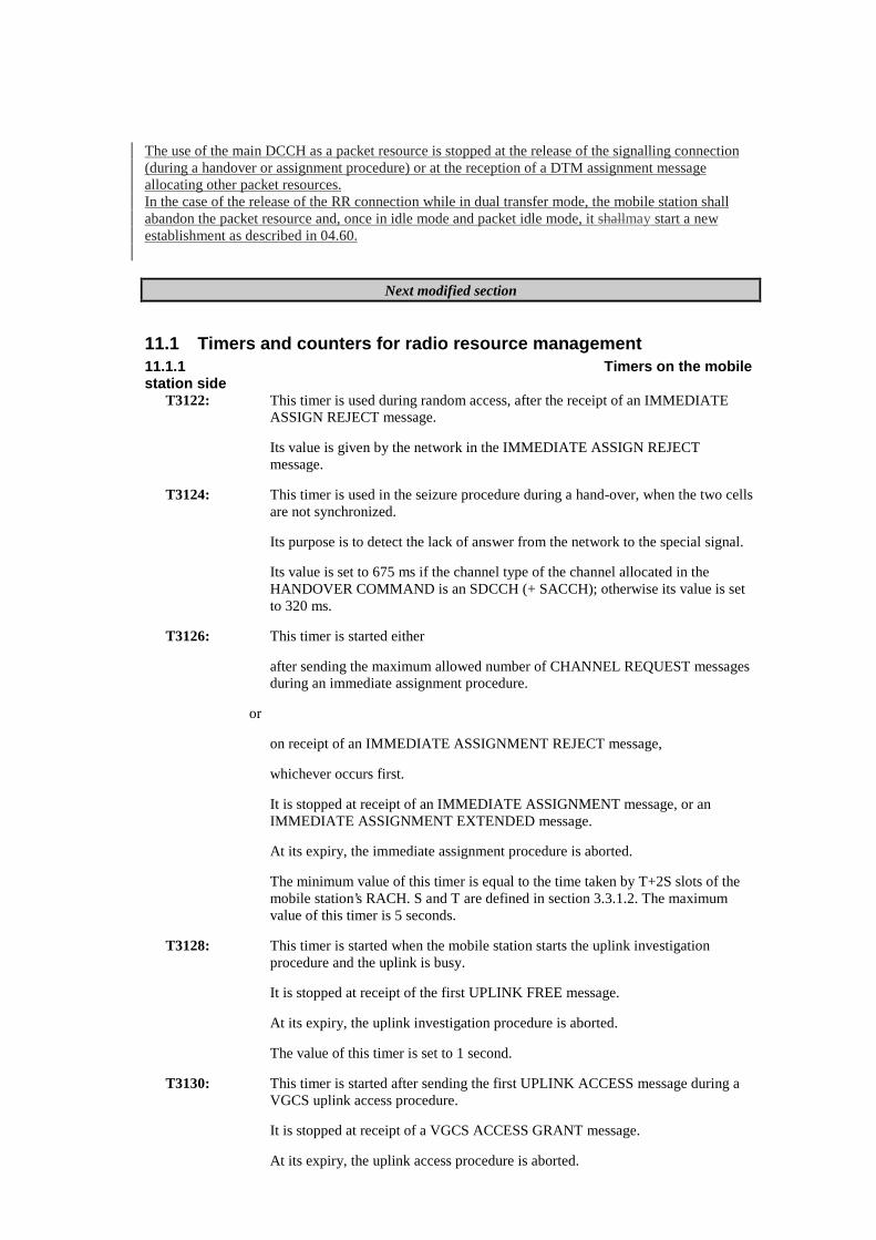
11.1 Timers and counters for radio resource management11.1.1 Timers on the mobilestation side
T3122: This timer is used during random access, after the receipt of an IMMEDIATEASSIGN REJECT message.
Its value is given by the network in the IMMEDIATE ASSIGN REJECTmessage.
T3124: This timer is used in the seizure procedure during a hand-over, when the two cellsare not synchronized.
Its purpose is to detect the lack of answer from the network to the special signal.
Its value is set to 675 ms if the channel type of the channel allocated in theHANDOVER COMMAND is an SDCCH (+ SACCH); otherwise its value is setto 320 ms.
T3126: This timer is started either
after sending the maximum allowed number of CHANNEL REQUEST messagesduring an immediate assignment procedure.
or
on receipt of an IMMEDIATE ASSIGNMENT REJECT message,
whichever occurs first.
It is stopped at receipt of an IMMEDIATE ASSIGNMENT message, or anIMMEDIATE ASSIGNMENT EXTENDED message.
At its expiry, the immediate assignment procedure is aborted.
The minimum value of this timer is equal to the time taken by T+2S slots of themobile station’s RACH. S and T are defined in section 3.3.1.2. The maximumvalue of this timer is 5 seconds.
T3128: This timer is started when the mobile station starts the uplink investigationprocedure and the uplink is busy.
It is stopped at receipt of the first UPLINK FREE message.
At its expiry, the uplink investigation procedure is aborted.
The value of this timer is set to 1 second.
T3130: This timer is started after sending the first UPLINK ACCESS message during aVGCS uplink access procedure.
It is stopped at receipt of a VGCS ACCESS GRANT message.
At its expiry, the uplink access procedure is aborted.
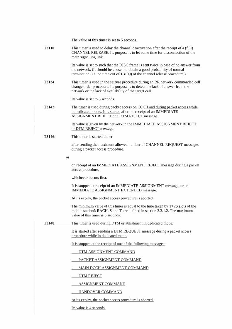
The value of this timer is set to 5 seconds.
T3110: This timer is used to delay the channel deactivation after the receipt of a (full)CHANNEL RELEASE. Its purpose is to let some time for disconnection of themain signalling link.
Its value is set to such that the DISC frame is sent twice in case of no answer fromthe network. (It should be chosen to obtain a good probability of normaltermination (i.e. no time out of T3109) of the channel release procedure.)
T3134 This timer is used in the seizure procedure during an RR network commanded cellchange order procedure. Its purpose is to detect the lack of answer from thenetwork or the lack of availability of the target cell.
Its value is set to 5 seconds.
T3142: The timer is used during packet access on CCCH and during packet access whilein dedicated mode., It is started after the receipt of an IMMEDIATEASSIGNMENT REJECT or a DTM REJECT message.
Its value is given by the network in the IMMEDIATE ASSIGNMENT REJECTor DTM REJECT message.
T3146: This timer is started either
after sending the maximum allowed number of CHANNEL REQUEST messagesduring a packet access procedure.
or
on receipt of an IMMEDIATE ASSIGNMENT REJECT message during a packetaccess procedure,
whichever occurs first.
It is stopped at receipt of an IMMEDIATE ASSIGNMENT message, or anIMMEDIATE ASSIGNMENT EXTENDED message.
At its expiry, the packet access procedure is aborted.
The minimum value of this timer is equal to the time taken by T+2S slots of themobile station’s RACH. S and T are defined in section 3.3.1.2. The maximumvalue of this timer is 5 seconds.
T3148: This timer is used during DTM establishment in dedicated mode.
It is started after sending a DTM REQUEST message during a packet accessprocedure while in dedicated mode.
It is stopped at the receipt of one of the following messages:
- DTM ASSIGNMENT COMMAND
- PACKET ASSIGNMENT COMMAND
- MAIN DCCH ASSIGNMENT COMMAND
- DTM REJECT
- ASSIGNMENT COMMAND
- HANDOVER COMMAND
At its expiry, the packet access procedure is aborted.
Its value is 4 seconds.
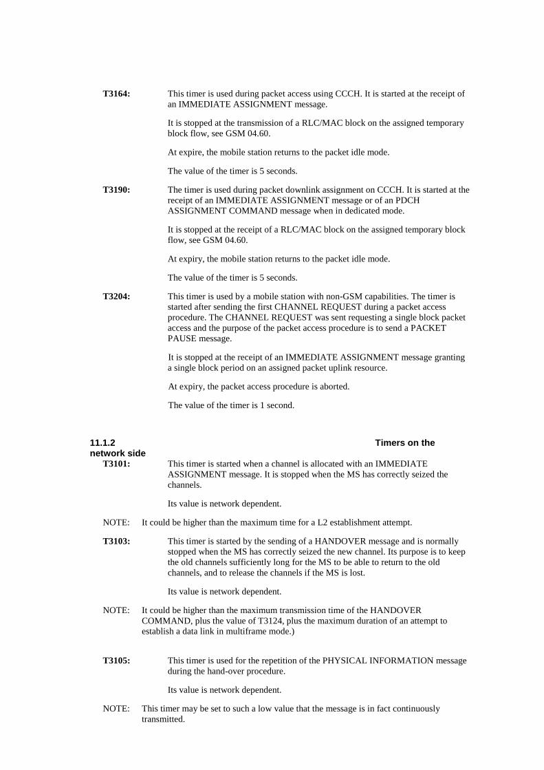
T3164: This timer is used during packet access using CCCH. It is started at the receipt ofan IMMEDIATE ASSIGNMENT message.
It is stopped at the transmission of a RLC/MAC block on the assigned temporaryblock flow, see GSM 04.60.
At expire, the mobile station returns to the packet idle mode.
The value of the timer is 5 seconds.
T3190: The timer is used during packet downlink assignment on CCCH. It is started at thereceipt of an IMMEDIATE ASSIGNMENT message or of an PDCHASSIGNMENT COMMAND message when in dedicated mode.
It is stopped at the receipt of a RLC/MAC block on the assigned temporary blockflow, see GSM 04.60.
At expiry, the mobile station returns to the packet idle mode.
The value of the timer is 5 seconds.
T3204: This timer is used by a mobile station with non-GSM capabilities. The timer isstarted after sending the first CHANNEL REQUEST during a packet accessprocedure. The CHANNEL REQUEST was sent requesting a single block packetaccess and the purpose of the packet access procedure is to send a PACKETPAUSE message.
It is stopped at the receipt of an IMMEDIATE ASSIGNMENT message grantinga single block period on an assigned packet uplink resource.
At expiry, the packet access procedure is aborted.
The value of the timer is 1 second.
11.1.2 Timers on thenetwork side
T3101: This timer is started when a channel is allocated with an IMMEDIATEASSIGNMENT message. It is stopped when the MS has correctly seized thechannels.
Its value is network dependent.
NOTE: It could be higher than the maximum time for a L2 establishment attempt.
T3103: This timer is started by the sending of a HANDOVER message and is normallystopped when the MS has correctly seized the new channel. Its purpose is to keepthe old channels sufficiently long for the MS to be able to return to the oldchannels, and to release the channels if the MS is lost.
Its value is network dependent.
NOTE: It could be higher than the maximum transmission time of the HANDOVERCOMMAND, plus the value of T3124, plus the maximum duration of an attempt toestablish a data link in multiframe mode.)
T3105: This timer is used for the repetition of the PHYSICAL INFORMATION messageduring the hand-over procedure.
Its value is network dependent.
NOTE: This timer may be set to such a low value that the message is in fact continuouslytransmitted.
T3107: This timer is started by the sending of an ASSIGNMENT COMMAND or a DTMASSIGNMENT COMMAND message and is normally stopped when the MS hascorrectly seized the new RR channels.
Its purpose is to keep the old channel sufficiently long for the MS to be able toreturn to the old channels, and to release the channels if the MS is lost.
Its value is network dependent.
NOTE: It could be higher than the maximum transmission time of the ASSIGNMENTCOMMAND message plus twice the maximum duration of an attempt to establish a datalink multiframe mode.
T3109: This timer is started when a lower layer failure is detected by the network, when itis not engaged in a RF procedure. It is also used in the channel release procedure.
Its purpose is to release the channels in case of loss of communication.
Its value is network dependent.
NOTE: Its value should be large enough to ensure that the MS detects a radio link failure.
T3111: This timer is used to delay the channel deactivation after disconnection of themain signalling link. Its purpose is to let some time for possible repetition of thedisconnection.
Its value is equal to the value of T3110.
T3113: This timer is started when the network has sent a PAGING REQUEST messageand is stopped when the network has received the PAGING RESPONSE message.
Its value is network dependent.
NOTE: The value could allow for repetitions of the Channel Request message and therequirements associated with T3101.
T3115: This timer is used for the repetition of the VGCS UPLINK GRANT messageduring the uplink access procedure.
Its value is network dependent.
NOTE: This timer may be set to such a low value that the message is in fact continuouslytransmitted.
T3117: This timer is started by the sending of a PDCH ASSIGNMENT COMMANDmessage and is normally stopped when the MS has correctly accessed the targetTBF.
Its purpose is to keep the old channel sufficiently long for the MS to be able toreturn to the old channels, and to release the channels if the MS is lost.
Its value is network dependent.
NOTE: It could be higher than the maximum transmission time of the PDCH ASSIGNMENTCOMMAND message plus T3132 plus the maximum duration of an attempt to establisha data link in multiframe mode.
T3119: This timer is started by the sending of a RR-CELL CHANGE ORDER messageand is normally stopped when the MS has correctly accessed the new cell. Itspurpose is to keep the old channels sufficiently long for the MS to be able toreturn to the old channels, and to release the channels if the MS is lost.
Its value is network dependent.
NOTE: It could be higher than the maximum transmission time of the RR_CELL CHANGEORDER, plus T3134, plus the maximum duration of an attempt to establish a data link inmultiframe mode.
T3141: This timer is started when a temporary block flow is allocated with anIMMEDIATE ASSIGNMENT message during a packet access procedure. It isstopped when the mobile station has correctly seized the temporary block flow.
Its value is network dependent.
11.1.3 Other parametersNy1: The maximum number of repetitions for the PHYSICAL INFORMATION
message during a handover (see section 3.4.4.2.2). The value is networkdependent.
Ny2: The maximum number of repetitions for the VGCS UPLINK GRANT messageduring an uplink access procedure (see section 3.3.1.2.2). The value is networkdependent.
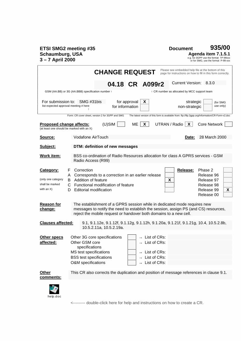
ETSI SMG2 meeting #35 Document 935/00Schaumburg, USA3 – 7 April 2000
Agenda item 7.1.5.1e.g. for 3GPP use the format TP-99xxx
or for SMG, use the format P-99-xxx
CHANGE REQUEST Please see embedded help file at the bottom of thispage for instructions on how to fill in this form correctly.
Current Version: 8.3.004.18 CR A099r2GSM (AA.BB) or 3G (AA.BBB) specification number ↑ ↑ CR number as allocated by MCC support team
For submission to: SMG #31bis for approval X strategic (for SMGlist expected approval meeting # here
↑for information non-strategic use only)
Form: CR cover sheet, version 2 for 3GPP and SMG The latest version of this form is available from: ftp://ftp.3gpp.org/Information/CR-Form-v2.doc
Proposed change affects: (U)SIM ME X UTRAN / Radio X Core Network(at least one should be marked with an X)
Source: Vodafone AirTouch Date: 28 March 2000
Subject: DTM: definition of new messages
Work item: BSS co-ordination of Radio Resources allocation for class A GPRS services - GSMRadio Access (R99)
Category: F Correction Release: Phase 2A Corresponds to a correction in an earlier release Release 96
(only one category B Addition of feature X Release 97shall be marked C Functional modification of feature Release 98with an X) D Editorial modification Release 99 X
Release 00
Reason forchange:
The establishment of a GPRS session while in dedicated mode requires newmessages to notify the need to establish the session, assign PS (and CS) resources,reject the mobile request or handover both domains to a new cell.
Clauses affected: 9.1, 9.1.12e, 9.1.12f, 9.1.12g, 9.1.12h, 9.1.20a, 9.1.21f, 9.1.21g, 10.4, 10.5.2.8b,10.5.2.11a, 10.5.2.19a.
Other specs Other 3G core specifications → List of CRs:affected: Other GSM core
specifications→ List of CRs:
MS test specifications → List of CRs:BSS test specifications → List of CRs:O&M specifications → List of CRs:
Othercomments:
This CR also corrects the duplication and position of message references in clause 9.1.
help.doc
<--------- double-click here for help and instructions on how to create a CR.
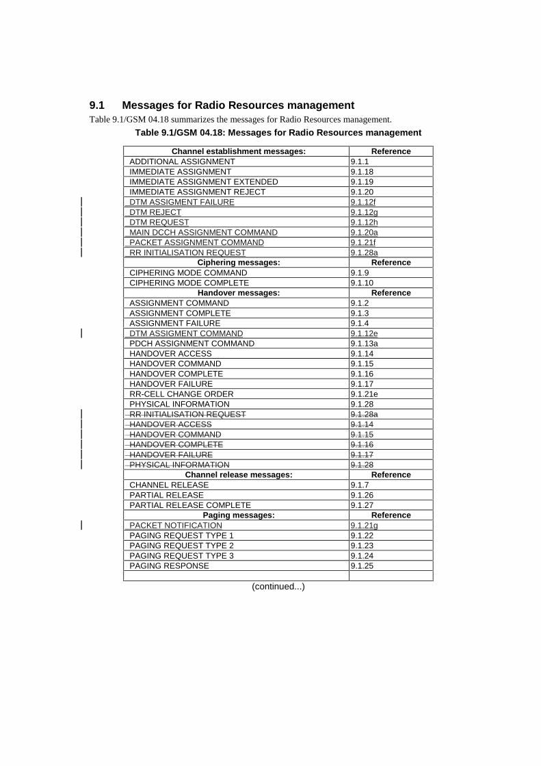
9.1 Messages for Radio Resources managementTable 9.1/GSM 04.18 summarizes the messages for Radio Resources management.
Table 9.1/GSM 04.18: Messages for Radio Resources management
Channel establishment messages: Reference ADDITIONAL ASSIGNMENT 9.1.1 IMMEDIATE ASSIGNMENT 9.1.18 IMMEDIATE ASSIGNMENT EXTENDED 9.1.19 IMMEDIATE ASSIGNMENT REJECT 9.1.20 DTM ASSIGMENT FAILURE 9.1.12f DTM REJECT 9.1.12g DTM REQUEST 9.1.12h MAIN DCCH ASSIGNMENT COMMAND 9.1.20a PACKET ASSIGNMENT COMMAND 9.1.21f RR INITIALISATION REQUEST 9.1.28a
Ciphering messages: Reference CIPHERING MODE COMMAND 9.1.9 CIPHERING MODE COMPLETE 9.1.10
Handover messages: Reference ASSIGNMENT COMMAND 9.1.2 ASSIGNMENT COMPLETE 9.1.3 ASSIGNMENT FAILURE 9.1.4 DTM ASSIGMENT COMMAND 9.1.12e PDCH ASSIGNMENT COMMAND 9.1.13a HANDOVER ACCESS 9.1.14 HANDOVER COMMAND 9.1.15 HANDOVER COMPLETE 9.1.16 HANDOVER FAILURE 9.1.17 RR-CELL CHANGE ORDER 9.1.21e PHYSICAL INFORMATION 9.1.28 RR INITIALISATION REQUEST 9.1.28a HANDOVER ACCESS 9.1.14 HANDOVER COMMAND 9.1.15 HANDOVER COMPLETE 9.1.16 HANDOVER FAILURE 9.1.17 PHYSICAL INFORMATION 9.1.28
Channel release messages: Reference CHANNEL RELEASE 9.1.7 PARTIAL RELEASE 9.1.26 PARTIAL RELEASE COMPLETE 9.1.27
Paging messages: Reference PACKET NOTIFICATION 9.1.21g PAGING REQUEST TYPE 1 9.1.22 PAGING REQUEST TYPE 2 9.1.23 PAGING REQUEST TYPE 3 9.1.24 PAGING RESPONSE 9.1.25
(continued...)
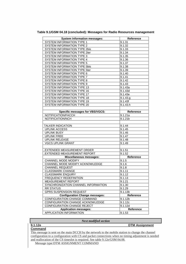
Table 9.1/GSM 04.18 (concluded): Messages for Radio Resources management
System information messages: Reference SYSTEM INFORMATION TYPE 1 9.1.31 SYSTEM INFORMATION TYPE 2 9.1.32 SYSTEM INFORMATION TYPE 2bis 9.1.33 SYSTEM INFORMATION TYPE 2ter 9.1.34 SYSTEM INFORMATION TYPE 3 9.1.35 SYSTEM INFORMATION TYPE 4 9.1.36 SYSTEM INFORMATION TYPE 5 9.1.37 SYSTEM INFORMATION TYPE 5bis 9.1.38 SYSTEM INFORMATION TYPE 5ter 9.1.39 SYSTEM INFORMATION TYPE 6 9.1.40 SYSTEM INFORMATION TYPE 7 9.1.41 SYSTEM INFORMATION TYPE 8 9.1.42 SYSTEM INFORMATION TYPE 9 9.1.43 SYSTEM INFORMATION TYPE 13 9.1.43a SYSTEM INFORMATION TYPE 16 9.1.43d SYSTEM INFORMATION TYPE 17 9.1.43e SYSTEM INFORMATION TYPE 18 9.1.43.g SYSTEM INFORMATION TYPE 19 9.1.43f SYSTEM INFORMATION TYPE 20 9.1.43.h
Specific messages for VBS/VGCS: Reference NOTIFICATION/FACCH 9.1.21a NOTIFICATION/NCH 9.1.21b
TALKER INDICATION 9.1.44 UPLINK ACCESS 9.1.45 UPLINK BUSY 9.1.46 UPLINK FREE 9.1.47 UPLINK RELEASE 9.1.48 VGCS UPLINK GRANT 9.1.49
..EXTENDED MEASUREMENT ORDER 9.1.51
..EXTENDED MEASUREMENT REPORT 9.1.52 Miscellaneous messages: Reference
CHANNEL MODE MODIFY 9.1.5 CHANNEL MODE MODIFY ACKNOWLEDGE 9.1.6 CHANNEL REQUEST 9.1.8 CLASSMARK CHANGE 9.1.11 CLASSMARK ENQUIRY 9.1.12 FREQUENCY REDEFINITION 9.1.13 MEASUREMENT REPORT 9.1.21 SYNCHRONIZATION CHANNEL INFORMATION 9.1.30 RR STATUS 9.1.29 GPRS SUSPENSION REQUEST 9.1.13b
Configuration Change messages: Reference CONFIGURATION CHANGE COMMAND 9.1.12b CONFIGURATION CHANGE ACKNOWLEDGE 9.1.12c CONFIGURATION CHANGE REJECT 9.1.12d Application messages: Reference APPLICATION INFORMATION 9.1.53
Next modified section9.1.12e DTM AssignmentCommandThis message is sent on the main DCCH by the network to the mobile station to change the channelconfiguration to a configuration with CS and packet connections when no timing adjustment is neededand reallocation of the CS timeslot is required. See table 9.12e/GSM 04.08.
Message type: DTM ASSIGNMENT COMMAND
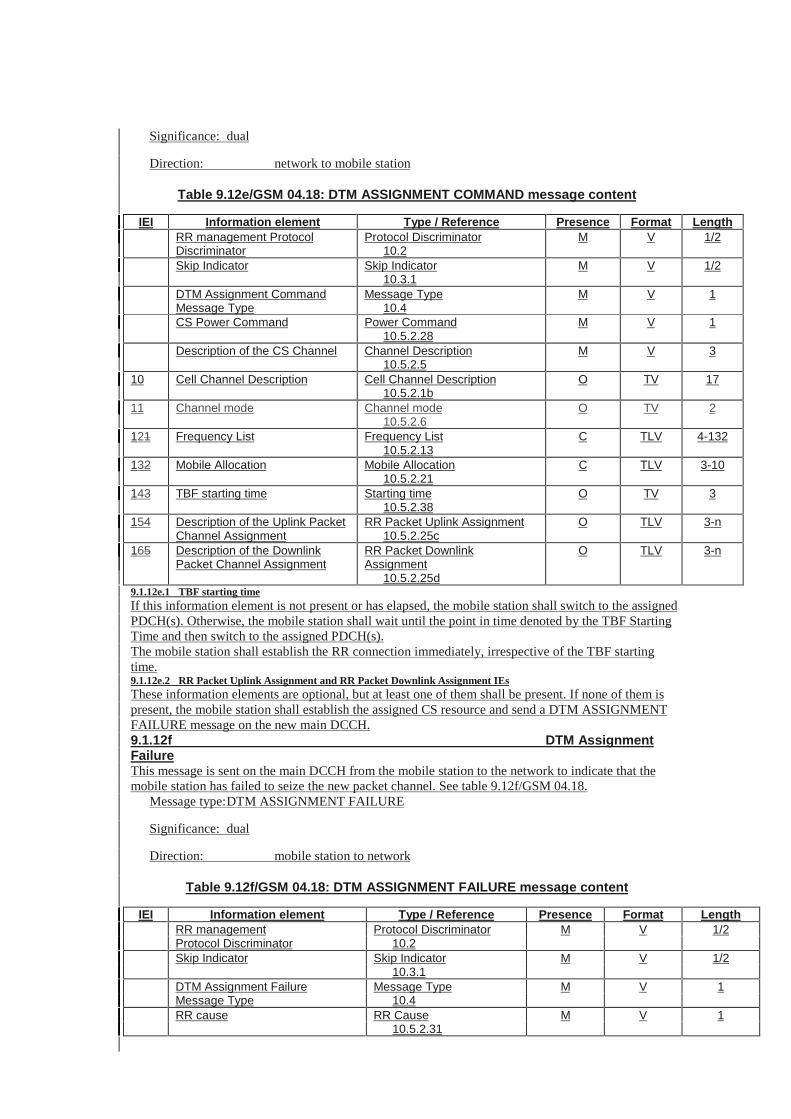
Significance: dual
Direction: network to mobile station
Table 9.12e/GSM 04.18: DTM ASSIGNMENT COMMAND message content
IEI Information element Type / Reference Presence Format LengthRR management ProtocolDiscriminator
Protocol Discriminator10.2
M V 1/2
Skip Indicator Skip Indicator10.3.1
M V 1/2
DTM Assignment CommandMessage Type
Message Type10.4
M V 1
CS Power Command Power Command10.5.2.28
M V 1
Description of the CS Channel Channel Description10.5.2.5
M V 3
10 Cell Channel Description Cell Channel Description10.5.2.1b
O TV 17
11 Channel mode Channel mode10.5.2.6
O TV 2
121 Frequency List Frequency List10.5.2.13
C TLV 4-132
132 Mobile Allocation Mobile Allocation10.5.2.21
C TLV 3-10
143 TBF starting time Starting time10.5.2.38
O TV 3
154 Description of the Uplink PacketChannel Assignment
RR Packet Uplink Assignment10.5.2.25c
O TLV 3-n
165 Description of the DownlinkPacket Channel Assignment
RR Packet DownlinkAssignment
10.5.2.25d
O TLV 3-n
9.1.12e.1 TBF starting timeIf this information element is not present or has elapsed, the mobile station shall switch to the assignedPDCH(s). Otherwise, the mobile station shall wait until the point in time denoted by the TBF StartingTime and then switch to the assigned PDCH(s).The mobile station shall establish the RR connection immediately, irrespective of the TBF startingtime.9.1.12e.2 RR Packet Uplink Assignment and RR Packet Downlink Assignment IEsThese information elements are optional, but at least one of them shall be present. If none of them ispresent, the mobile station shall establish the assigned CS resource and send a DTM ASSIGNMENTFAILURE message on the new main DCCH.9.1.12f DTM AssignmentFailureThis message is sent on the main DCCH from the mobile station to the network to indicate that themobile station has failed to seize the new packet channel. See table 9.12f/GSM 04.18.
Message type: DTM ASSIGNMENT FAILURE
Significance: dual
Direction: mobile station to network
Table 9.12f/GSM 04.18: DTM ASSIGNMENT FAILURE message content
IEI Information element Type / Reference Presence Format LengthRR management Protocol Discriminator M V 1/2Protocol Discriminator 10.2Skip Indicator Skip Indicator M V 1/2
10.3.1DTM Assignment Failure Message Type M V 1Message Type 10.4RR cause RR Cause M V 1
10.5.2.31
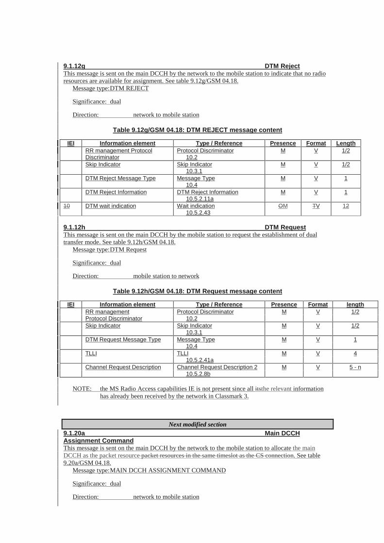
9.1.12g DTM RejectThis message is sent on the main DCCH by the network to the mobile station to indicate that no radioresources are available for assignment. See table 9.12g/GSM 04.18.
Message type: DTM REJECT
Significance: dual
Direction: network to mobile station
Table 9.12g/GSM 04.18: DTM REJECT message content
IEI Information element Type / Reference Presence Format LengthRR management ProtocolDiscriminator
Protocol Discriminator10.2
M V 1/2
Skip Indicator Skip Indicator10.3.1
M V 1/2
DTM Reject Message Type Message Type10.4
M V 1
DTM Reject Information DTM Reject Information10.5.2.11a
M V 1
10 DTM wait indication Wait indication10.5.2.43
OM TV 12
9.1.12h DTM RequestThis message is sent on the main DCCH by the mobile station to request the establishment of dualtransfer mode. See table 9.12h/GSM 04.18.
Message type: DTM Request
Significance: dual
Direction: mobile station to network
Table 9.12h/GSM 04.18: DTM Request message content
IEI Information element Type / Reference Presence Format lengthRR management Protocol Discriminator M V 1/2Protocol Discriminator 10.2Skip Indicator Skip Indicator M V 1/2
10.3.1DTM Request Message Type Message Type M V 1
10.4TLLI TLLI M V 4
10.5.2.41aChannel Request Description Channel Request Description 2 M V 5 - n
10.5.2.8b
NOTE: the MS Radio Access capabilities IE is not present since all itsthe relevant informationhas already been received by the network in Classmark 3.
Next modified section9.1.20a Main DCCHAssignment CommandThis message is sent on the main DCCH by the network to the mobile station to allocate the mainDCCH as the packet resource packet resources in the same timeslot as the CS connection. See table9.20a/GSM 04.18.
Message type: MAIN DCCH ASSIGNMENT COMMAND
Significance: dual
Direction: network to mobile station
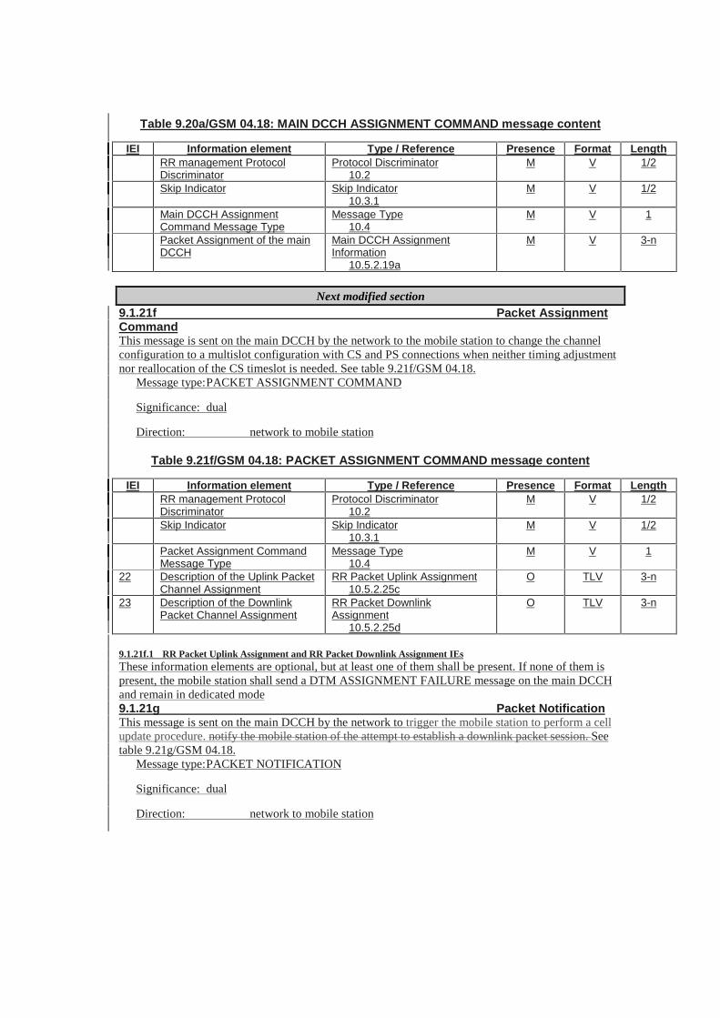
Table 9.20a/GSM 04.18: MAIN DCCH ASSIGNMENT COMMAND message content
IEI Information element Type / Reference Presence Format LengthRR management ProtocolDiscriminator
Protocol Discriminator10.2
M V 1/2
Skip Indicator Skip Indicator10.3.1
M V 1/2
Main DCCH AssignmentCommand Message Type
Message Type10.4
M V 1
Packet Assignment of the mainDCCH
Main DCCH AssignmentInformation
10.5.2.19a
M V 3-n
Next modified section9.1.21f Packet AssignmentCommandThis message is sent on the main DCCH by the network to the mobile station to change the channelconfiguration to a multislot configuration with CS and PS connections when neither timing adjustmentnor reallocation of the CS timeslot is needed. See table 9.21f/GSM 04.18.
Message type: PACKET ASSIGNMENT COMMAND
Significance: dual
Direction: network to mobile station
Table 9.21f/GSM 04.18: PACKET ASSIGNMENT COMMAND message content
IEI Information element Type / Reference Presence Format LengthRR management ProtocolDiscriminator
Protocol Discriminator10.2
M V 1/2
Skip Indicator Skip Indicator10.3.1
M V 1/2
Packet Assignment CommandMessage Type
Message Type10.4
M V 1
22 Description of the Uplink PacketChannel Assignment
RR Packet Uplink Assignment10.5.2.25c
O TLV 3-n
23 Description of the DownlinkPacket Channel Assignment
RR Packet DownlinkAssignment
10.5.2.25d
O TLV 3-n
9.1.21f.1 RR Packet Uplink Assignment and RR Packet Downlink Assignment IEsThese information elements are optional, but at least one of them shall be present. If none of them ispresent, the mobile station shall send a DTM ASSIGNMENT FAILURE message on the main DCCHand remain in dedicated mode9.1.21g Packet NotificationThis message is sent on the main DCCH by the network to trigger the mobile station to perform a cellupdate procedure. notify the mobile station of the attempt to establish a downlink packet session. Seetable 9.21g/GSM 04.18.
Message type: PACKET NOTIFICATION
Significance: dual
Direction: network to mobile station
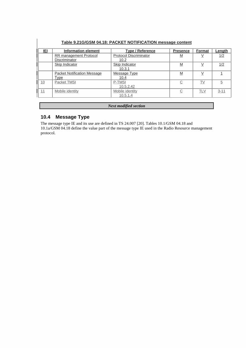
Table 9.21G/GSM 04.18: PACKET NOTIFICATION message content
IEI Information element Type / Reference Presence Format LengthRR management ProtocolDiscriminator
Protocol Discriminator10.2
M V 1/2
Skip Indicator Skip Indicator10.3.1
M V 1/2
Packet Notification MessageType
Message Type10.4
M V 1
10 Packet TMSI P-TMSI10.5.2.42
C TV 5
11 Mobile identity Mobile identity10.5.1.4
C TLV 3-11
Next modified section
10.4 Message TypeThe message type IE and its use are defined in TS 24.007 [20]. Tables 10.1/GSM 04.18 and10.1a/GSM 04.18 define the value part of the message type IE used in the Radio Resource managementprotocol.
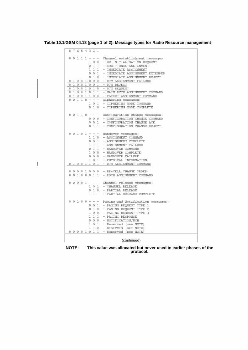
Table 10.1/GSM 04.18 (page 1 of 2): Message types for Radio Resource management
8 7 6 5 4 3 2 1
0 0 1 1 1 - - - Channel establishment messages: 1 0 0 - RR INITIALISATION REQUEST 0 1 1 - ADDITIONAL ASSIGNMENT 1 1 1 - IMMEDIATE ASSIGNMENT 0 0 1 - IMMEDIATE ASSIGNMENT EXTENDED 0 1 0 - IMMEDIATE ASSIGNMENT REJECT 0 1 0 0 1 0 0 0 - DTM ASSIGNMENT FAILURE 0 1 0 0 1 0 0 1 - DTM REJECT 0 1 0 0 1 0 1 0 - DTM REQUEST 0 1 0 0 1 0 1 1 - MAIN DCCH ASSIGNMENT COMMAND 0 1 0 0 1 1 0 0 - PACKET ASSIGNMENT COMMAND 0 0 1 1 0 - - - Ciphering messages: 1 0 1 - CIPHERING MODE COMMAND 0 1 0 - CIPHERING MODE COMPLETE
0 0 1 1 0 - - - Configuration change messages: 0 0 0 - CONFIGURATION CHANGE COMMAND 0 0 1 - CONFIGURATION CHANGE ACK. 0 1 1 - CONFIGURATION CHANGE REJECT
0 0 1 0 1 - - - Handover messages: 1 1 0 - ASSIGNMENT COMMAND 0 0 1 - ASSIGNMENT COMPLETE 1 1 1 - ASSIGNMENT FAILURE 0 1 1 - HANDOVER COMMAND 1 0 0 - HANDOVER COMPLETE 0 0 0 - HANDOVER FAILURE 1 0 1 - PHYSICAL INFORMATION 0 1 0 0 1 1 0 1 - DTM ASSIGNMENT COMMAND
0 0 0 0 1 0 0 0 - RR-CELL CHANGE ORDER 0 0 1 0 0 0 1 1 - PDCH ASSIGNMENT COMMAND
0 0 0 0 1 - - - Channel release messages: 1 0 1 - CHANNEL RELEASE 0 1 0 - PARTIAL RELEASE 1 1 1 - PARTIAL RELEASE COMPLETE
0 0 1 0 0 - - - Paging and Notification messages: 0 0 1 - PAGING REQUEST TYPE 1 0 1 0 - PAGING REQUEST TYPE 2 1 0 0 - PAGING REQUEST TYPE 3 1 1 1 - PAGING RESPONSE 0 0 0 - NOTIFICATION/NCH 1 0 1 - Reserved (see NOTE) 1 1 0 - Reserved (see NOTE) 0 0 0 0 1 0 1 1 - Reserved (see NOTE)
(continued)
NOTE: This value was allocated but never used in earlier phases of theprotocol.
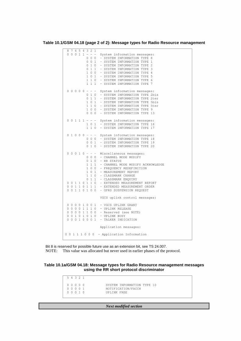
Table 10.1/GSM 04.18 (page 2 of 2): Message types for Radio Resource management
8 7 6 5 4 3 2 1 0 0 0 1 1 - - - System information messages: 0 0 0 - SYSTEM INFORMATION TYPE 8 0 0 1 - SYSTEM INFORMATION TYPE 1 0 1 0 - SYSTEM INFORMATION TYPE 2 0 1 1 - SYSTEM INFORMATION TYPE 3 1 0 0 - SYSTEM INFORMATION TYPE 4 1 0 1 - SYSTEM INFORMATION TYPE 5 1 1 0 - SYSTEM INFORMATION TYPE 6 1 1 1 - SYSTEM INFORMATION TYPE 7
0 0 0 0 0 - - - System information messages: 0 1 0 - SYSTEM INFORMATION TYPE 2bis 0 1 1 - SYSTEM INFORMATION TYPE 2ter 1 0 1 - SYSTEM INFORMATION TYPE 5bis 1 1 0 - SYSTEM INFORMATION TYPE 5ter 1 0 0 - SYSTEM INFORMATION TYPE 9 0 0 0 - SYSTEM INFORMATION TYPE 13
0 0 1 1 1 - - - System information messages: 1 0 1 - SYSTEM INFORMATION TYPE 16 1 1 0 - SYSTEM INFORMATION TYPE 17
0 1 0 0 0 - - - System information messages: 0 0 0 - SYSTEM INFORMATION TYPE 18 0 0 1 - SYSTEM INFORMATION TYPE 19 0 1 0 - SYSTEM INFORMATION TYPE 20
0 0 0 1 0 - - - Miscellaneous messages: 0 0 0 - CHANNEL MODE MODIFY 0 1 0 - RR STATUS 1 1 1 - CHANNEL MODE MODIFY ACKNOWLEDGE 1 0 0 - FREQUENCY REDEFINITION 1 0 1 - MEASUREMENT REPORT 1 1 0 - CLASSMARK CHANGE 0 1 1 - CLASSMARK ENQUIRY 0 0 1 1 0 1 1 0 - EXTENDED MEASUREMENT REPORT 0 0 1 1 0 1 1 1 - EXTENDED MEASUREMENT ORDER 0 0 1 1 0 1 0 0 - GPRS SUSPENSION REQUEST
VGCS uplink control messages:
0 0 0 0 1 0 0 1 - VGCS UPLINK GRANT 0 0 0 0 1 1 1 0 - UPLINK RELEASE 0 0 0 0 1 1 0 0 - Reserved (see NOTE) 0 0 1 0 1 0 1 0 - UPLINK BUSY 0 0 0 1 0 0 0 1 - TALKER INDICATION
Application messages:
0 0 1 1 1 0 0 0 - Application Information
Bit 8 is reserved for possible future use as an extension bit, see TS 24.007.NOTE: This value was allocated but never used in earlier phases of the protocol.
Table 10.1a/GSM 04.18: Message types for Radio Resource management messagesusing the RR short protocol discriminator
5 4 3 2 1
0 0 0 0 0 SYSTEM INFORMATION TYPE 10 0 0 0 0 1 NOTIFICATION/FACCH 0 0 0 1 0 UPLINK FREE
Next modified section
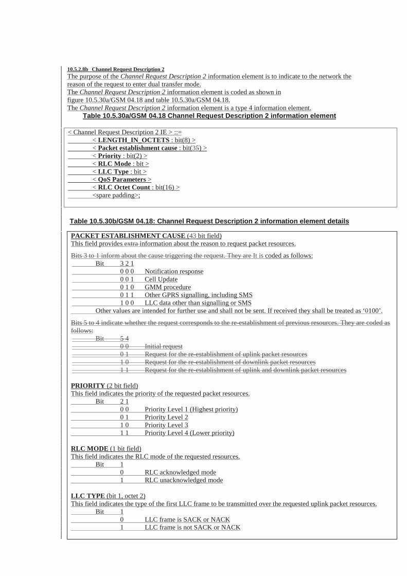
10.5.2.8b Channel Request Description 2The purpose of the Channel Request Description 2 information element is to indicate to the network thereason of the request to enter dual transfer mode.The Channel Request Description 2 information element is coded as shown infigure 10.5.30a/GSM 04.18 and table 10.5.30a/GSM 04.18.The Channel Request Description 2 information element is a type 4 information element.
Table 10.5.30a/GSM 04.18 Channel Request Description 2 information element
< Channel Request Description 2 IE > ::= < LENGTH_IN_OCTETS : bit(8) > < Packet establishment cause : bit(35) > < Priority : bit(2) > < RLC Mode : bit > < LLC Type : bit > < QoS Parameters > < RLC Octet Count : bit(16) > <spare padding>;
Table 10.5.30b/GSM 04.18: Channel Request Description 2 information element details
PACKET ESTABLISHMENT CAUSE (43 bit field)This field provides extra information about the reason to request packet resources.
Bits 3 to 1 inform about the cause triggering the request. They are It is coded as follows: Bit 3 2 1 0 0 0 Notification response 0 0 1 Cell Update 0 1 0 GMM procedure 0 1 1 Other GPRS signalling, including SMS 1 0 0 LLC data other than signalling or SMS Other values are intended for further use and shall not be sent. If received they shall be treated as ‘0100’.
Bits 5 to 4 indicate whether the request corresponds to the re-establishment of previous resources. They are coded asfollows: Bit 5 4 0 0 Initial request 0 1 Request for the re-establishment of uplink packet resources 1 0 Request for the re-establishment of downlink packet resources 1 1 Request for the re-establishment of uplink and downlink packet resources
PRIORITY (2 bit field)This field indicates the priority of the requested packet resources. Bit 2 1 0 0 Priority Level 1 (Highest priority) 0 1 Priority Level 2 1 0 Priority Level 3 1 1 Priority Level 4 (Lower priority)
RLC MODE (1 bit field)This field indicates the RLC mode of the requested resources. Bit 1 0 RLC acknowledged mode 1 RLC unacknowledged mode
LLC TYPE (bit 1, octet 2)This field indicates the type of the first LLC frame to be transmitted over the requested uplink packet resources. Bit 1 0 LLC frame is SACK or NACK 1 LLC frame is not SACK or NACK
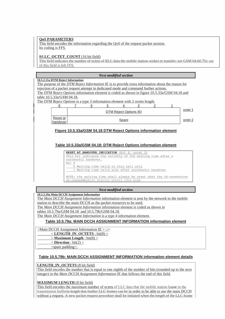
QoS PARAMETERSThis field encodes the information regarding the QoS of the request packet session.Its coding is FFS.
RLLC_OCTET_COUNT (16 bit field)This field indicates the number of octets of RLC data the mobile station wishes to transfer: see GSM 04.60.The useof this field is left FFS.
Next modified section10.5.2.11a DTM Reject InformationThe purpose of the DTM Reject Information IE is to provide extra information about the reason forrejection of a packet request attempt in dedicated mode and command further actions.The DTM Reject Options information element is coded as shown in figure 10.5.33a/GSM 04.18 andtable 10.5.33a/GSM 04.18.The DTM Reject Options is a type 3 information element with 2 octets length.
8 7 6 5 4 3 2 1
DTM Reject Options IEI octet 1
Reset athandover Spare octet 2
Figure 10.5.33a/GSM 04.18 DTM Reject Options information element
Table 10.5.33a/GSM 04.18: DTM Reject Options information element
RESET_AT_HANDOVER_INDICATION (bit 8, octet 2)This bit indicates the validity of the waiting time after asuccessful handover.Bit 8 0 Waiting time valid in this cell only 1 Waiting time valid also after successful handover
NOTE: the waiting time shall always be reset when the CS connectionis clearedmobile station enters idle mode
Next modified section10.5.2.19a Main DCCH Assignment InformationThe Main DCCH Assignment Information information element is sent by the network to the mobilestation to describe the main DCCH as the packet resources to be used.The Main DCCH Assignment Information information element is coded as shown intables 10.5.79a/GSM 04.18 and 10.5.79b/GSM 04.18.The Main DCCH Assignment Information is a type 4 information element.
Table 10.5.79a: MAIN DCCH ASSIGNMENT INFORMATION information element
<Main DCCH Assignment Information IE > ::= < LENGTH_IN_OCTETS : bit(8) > < Maximum Length : bit(8) > < Direction : bit(2) > <spare padding>;
Table 10.5.79b: MAIN DCCH ASSIGNMENT INFORMATION information element details
LENGTH_IN_OCTETS (8 bit field)This field encodes the number that is equal to one eighth of the number of bits (rounded up to the nextinteger) in the Main DCCH Assignment Information IE that follows the end of this field.
MAXIMUM LENGTH (8 bit field)This field encodes the maximum number of octets of LLC data that the mobile station hasve in thetransmission bufferin length that further LLC frames can be in order to be able to use the main DCCHwithout a request. A new packet request procedure shall be initiated when the length of the LLC frame

is above this value or when there is a change in any of the other parameters sent in the DTMREQUEST message.
DIRECTION (2 bit field)This field encodes direction on which the main DCCH is allocated as a packet resource. It is coded asfollows: Bit 2 1 0 0 Reserved 0 1 Uplink only 1 0 Downlink only 1 1 Uplink and downlink

SMG2 #35Schaumburg, Illinois, U.S.A., 3-7 April 2000
Document 2-00-847Agenda Item 7.1.5.1
CHANGE REQUEST Please see embedded help file at the bottom of thispage for instructions on how to fill in this form correctly.
Current Version: 8.3.004.60 CR A840GSM (AA.BB) or 3G (AA.BBB) specification number ↑ ↑ CR number as allocated by MCC support team
For submission to: SMG #32 for approval X strategic (for SMGlist expected approval meeting # here
↑for information non-strategic X use only)
Form: CR cover sheet, version 2 for 3GPP and SMG The latest version of this form is available from: ftp://ftp.3gpp.org/Information/CR-Form-v2.doc
Proposed change affects: (U)SIM ME X UTRAN / Radio X Core Network(at least one should be marked with an X)
Source: Motorola, Inc. Date: 5 April 2000
Subject: Correction to timer T3174 value
Work item: GPRS
Category: F Correction X Release: Phase 2A Corresponds to a correction in an earlier release Release 96
(only one category B Addition of feature Release 97shall be marked C Functional modification of feature Release 98with an X) D Editorial modification Release 99 X
Release 00
Reason forchange:
Value of timer T3174 is logically inconsistent with the amount of time required forprocessing actions to be performed between the time it is started and the time it expires.
The intention of T3174 is to protect against the failure of network controlled (NC) cellreselection. It is started upon the receipt of a PACKET CELL CHANGE ORDER message, andstopped upon the receipt of a CHANNEL REQUEST or a PACKET CHANNEL REQUEST inthe new cell. If T3174 expires in the process of selecting a new cell, then the mobile stationreturns to the old cell and sends a PACKET CELL CHANGE FAILURE.Problem: Once the mobile station has received the PACKET CELL CHANGE ORDER, theworst-case amount of time required for processing System Information (SI) and Packet SystemInformation (PSI) messages may exceed the current 5 second value of T3174.For example:- Reading of SI-13 (to find PBCCH) : maximum approximately 3 seconds based on message
periodicity- Reading of PSI-1, PSI-2 and PSI-3 (on PBCCH) : maximum approximately 16 * a 52-
frame multiframe period = 16 * 240 ms = 3.85 seconds.Total = 3 + 3.85 = 6.85 seconds + any additional time required for signalling overhead.In such cases, this would cause the mobile station to unnecessarily revert back to its previouscell, which is not what is intended by the specification.Solution: It is therefore proposed that timer T3174 be increased to an appropriate value. Thisproblem was acknowledged and discussed with several manufacturers, including Ericsson,Matsushita and Nokia. All agree that a reasonable value for T3174 would be 15 seconds.
Clauses affected: 13.1 Timers on the Mobile Station side
Other specs Other 3G core specifications → List of CRs:affected: Other GSM core
specifications→ List of CRs:

MS test specifications → List of CRs:BSS test specifications → List of CRs:O&M specifications → List of CRs:
Othercomments:

13.1 Timers on the Mobile Station side
Table 3: Specification of timers used in GPRS on the Mobile Station side
timer started stopped Action at expiry valueT3158 Started when ordered by a
NETWORK_CONTROL_ORDER and then restarted each timea Network Controlled (NC)Measurement is performed inMM Ready state and in packetidle or packet transfer mode
See 05.08 Restart the timer, perform themeasurement and send a NCMeasurement report. The timershall be restarted with either ofthe parametersNC_REPORTING_PERIOD_Iwhen in packet idle mode orwith the parameterNC_REPORTING_PERIOD_Twhen in packet transfer mode
Defined bytheparameteror by arandomvalue (seeGSM05.08)
T3162 On receipt of a PACKETQUEUING NOTIFICATION.
On receipt of a PACKETUPLINK ASSIGNMENT
Abort Packet access procedure;indicate Packet access failure toupper layers and Return topacket idle mode listening to itspaging subchannel
5 sec
T3164 On receipt of a PACKETUPLINK ASSIGNMENT
At sending of the first RLC/MACblock
See subclause 7.1.4. 5 sec
T3166 At sending of the first RLC/MACblock at one phase access
On receipt of a PACKETUPLINK ACK/NACK
Immediately stop transmitting onthe assigned TBF; a TBFestablishment failure hasoccurred or the contentionresolution procedures has failed
5 sec
T3168 At sending the PACKETRESOURCE REQUESTmessage or Channel RequestDescription IE in PACKETDOWNLINK ACK/NACK
On receipt of a PACKETUPLINK ASSIGNMENTmessage
Reinitiate the packet accessprocedure or retransmit thePACKET RESOURCEREQUEST or PACKETDOWNLINK ACK/NACK
assignedin systeminformation
T3170 After having made M + 1attempts to send a PACKETCHANNEL REQUESTmessage, or on receipt of aPACKET ACCESS REJECTmessage.
On receipt of a PACKETUPLINK ASSIGNMENT orPACKET QUEUINGNOTIFICATION message
Abort Packet access procedure,indicate Packet access failure toupper layer and return to PacketIdle mode
Defined byparameters TX_INTand S
T3172 On receipt of a PACKETACCESS REJECT message
On receipt of a PACKETUPLINK ASSIGNMENTmessage
Packet Access in the cell nolonger prohibited
assignedinmessage
Table 1 (continued): Specification of timers used in GPRS on the Mobile Station side
timer started stopped Action at expiry valueT3174 On receipt of a PACKET CELL
CHANGE ORDER messageOn receipt of a response toCHANNEL REQUEST orPACKET CHANNEL REQUESTin the new cell
Return to old cell and sendPACKET CELL CHANGEFAILURE
5 15 sec
T3176 Expiry of T3174 After sending of PACKET CELLCHANGE FAILURE message
Stop cell change order failureprocedure.
5 sec
T3178 Started when ordered by aEXT_MEASUREMENT_ORDERand then restarted each time anextended (EXT) Measurement isperformed in packet idle mode
See 05.08 Restart the timer, perform themeasurement and send an EXTMeasurement report. The timershall be restarted with theparameterEXT_REPORTING_PERIOD
Defined bytheparameteror by aRandomvalue (seeGSM05.08)
T3180 When transmitting an RLC/MACblock to the network
When detecting an assignedUSF value on assigned PDCH
Perform Abnormal release withrandom access procedure
5 sec
T3182 After sending the last data block(with CV = 0), or Upon detectinga transmit window stall condition
On receipt of the PACKETUPLINK ACK/NACK message
Abnormal release with randomaccess
5 sec

T3184 On receipt of a PACKETUPLINK ACK/NACK message
On receipt of PACKET UPLINKACK/NACK message(T3184 is also restarted)
Abnormal release with randomaccess
5 sec
T3186 When packet access procedureis started Stopped when receiving any
message from the network inresponse to the PACKETCHANNEL REQUEST messageor after M+1 attempts to sendPACKET CHANNEL REQUESTmessages on the PRACHchannel
Abort Packet access procedure;indicate Packet access failure toupper layers and return toPacket Idle mode.
5 sec
T3188 If a new fixed allocation hasbeen requested, when all datahas been sent on the assignedallocation
On receipt of PACKET UPLINKASSIGNMENT, PACKETUPLINK ACK/NACK messagecontaining a fixed allocation, orPACKET ACCESS REJECT
Resend the last allocationrequest if it needs more data tocomplete the TBF
5 sec
T3190 At reception of a downlinkassignment message
Restarted on receipt of data onthe resources
Abnormal release with return toCCCH or PCCCH
5 sec
T3192 At sending the PACKETDOWNLINK ACK/NACK withthe Final Ack Indicator=1, or atsending the PACKETCONTROL ACK as a responseto final RLC data block inunacknowledged mode.
Restarted at sending thePACKET DOWNLINKACK/NACK with the Final AckIndicator=1, or at sending thePACKET CONTROL ACK as aresponse to final RLC data blockin unacknowledged mode.Stopped at the reception of aPACKET DOWNLINKASSIGNMENT or PACKETTIMESLOT RECONFIGURE.
Release the resources, stopmonitoring the PDCHs, andbegin to monitor the pagingchannel
assignedin systeminformation
T3198 When transmitting RLC datablock
none Accept negativeacknowledgement for RLC datablock
see clause9.1.3
T3200 On receipt of an RLC/MACcontrol block containing asegment of an RLC/MAC controlmessage
On receipt of an RLC/MACcontrol block containing asegment of an RLC/MAC controlmessage such that the mobilestation now has the completecontrol message
Discard and ignore all segmentsof the partially receivedRLC/MAC control message
see clause9.1.11b
T3158: Wait for sending measurement reports for network controlled cell reselection.
This timer is used on the mobile station side to define the period for performingNC-measurements and send measurement reports in either packet idle or packettransfer mode (see GSM 05.08).
T3162: Wait for Packet Uplink Assignment after reception of Packet QueuingNotification
This timer is used on the mobile station side after received Packet QueuingNotification to define when to stop waiting for a Packet Uplink Assignment.
T3164: Wait for Uplink State Flag After Assignment
This timer is used on the mobile station side to define when to stop waiting for theUSF determining the assigned portion of the uplink channel and repeat theprocedure for random access. In multislot operation, it is enough that the assignedUSF is noted on one of the uplink PDCHs. This timer is not used when fixedallocations are assigned.
T3166: Wait for Packet Uplink ACK/NACK after sending of first data block
This timer is used on the mobile station side to define when to stop waiting for aPacket Uplink ACK/NACK after sending of the first data block.

T3168: Wait for Packet Uplink Assignment message
This timer is used on the mobile station side to define when to stop waiting for aPacket Uplink Assignment message after sending of a Packet Resource requestmessage.
T3170: Wait for Packet Uplink Assignment after having done (M+1) Packet ChannelRequests or after reception of a PACKET ACCESS REJECT message.
This timer is used on the mobile station side when having made M + 1 attempts tosend a Packet Channel Request or after reception of a PACKET ACCESSREJECT message. At expiry of timer T3170, the mobile station shall abort thepacket access procedure, indicate a packet access failure to upper layer and returnto packet idle mode.
The value of this timer is equal to the time taken by T+2S TDMA frames. T and Sare defined in subclause 7.1.2.1.1.
T3172: Prohibit packet access in the cell after Packet Access Reject message has beenreceived.
This timer is used on the mobile station side on receipt of a Packet Access Rejectmessage corresponding to one of the mobile station’s 3 last Packet ChannelRequest messages.
After T3172 expiry packet Access is no longer prohibited in the cell but noChannel Request message shall be sent as a response to a page until a PagingRequest message for the mobile station is received.
T3174: Wait for response on new cell after Packet Cell Change Order .
This timer is used on the mobile station side on receipt of a PACKET CELLCHANGE ORDER message. The timer is stopped upon successful access on thenew cell. On expiry, the mobile station returns to the old cell and send PACKETCELL CHANGE FAILURE message.
T3176: Stop Cell Change failure procedure .
This timer started when T3174 expires. The timer is stopped upon transmission ofthe PACKET CELL CHANGE FAILURE message. On expiry, the mobile stationstops attempting to send the PACKET CELL CHANGE FAILURE message.
T3178: Wait for sending extended measurement reports.
This timer is used on the mobile station side to define the period for performingextended measurements and send extended measurement reports in packet idlemode (see GSM 05.08).
T3180: Wait for Uplink State Flag After Data Block
This timer is used on the mobile station side to define when to stop waiting for theUSF determining the assigned portion of the uplink channel after the perviousRLC/MAC block is sent. In multislot operation, it is enough that the assignedUSF is noted on one of the uplink PDCHs. If expired, the mobile station repeatsthe procedure for random access. This timer does not apply to fixed allocationtransfers.
T3182: Wait for Acknowledgement
This timer is used on the mobile station side to define when to stop waiting fortemporary Packet Uplink Ack/Nack after the last RLC data block has been sentfor the current send window or for the entire Temporary Block Flow.
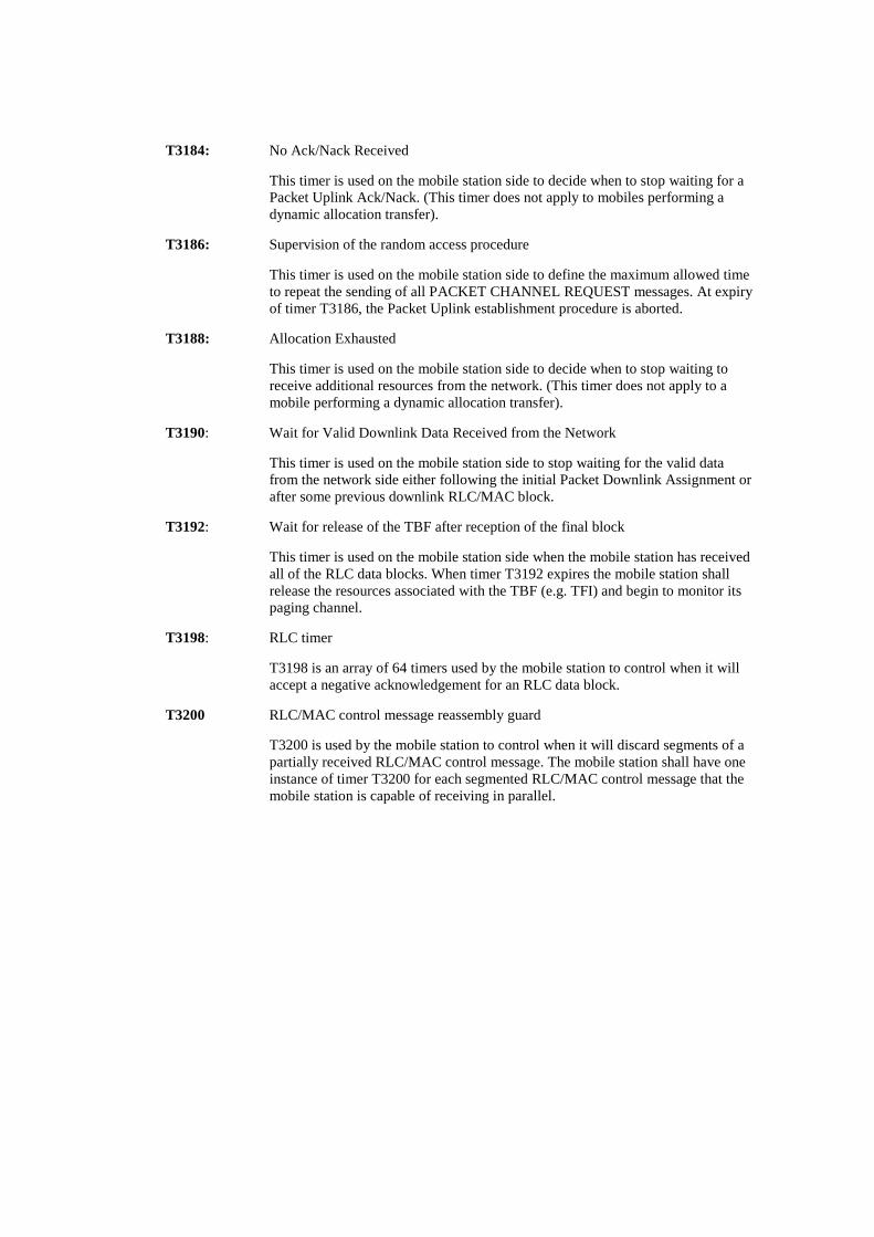
T3184: No Ack/Nack Received
This timer is used on the mobile station side to decide when to stop waiting for aPacket Uplink Ack/Nack. (This timer does not apply to mobiles performing adynamic allocation transfer).
T3186: Supervision of the random access procedure
This timer is used on the mobile station side to define the maximum allowed timeto repeat the sending of all PACKET CHANNEL REQUEST messages. At expiryof timer T3186, the Packet Uplink establishment procedure is aborted.
T3188: Allocation Exhausted
This timer is used on the mobile station side to decide when to stop waiting toreceive additional resources from the network. (This timer does not apply to amobile performing a dynamic allocation transfer).
T3190: Wait for Valid Downlink Data Received from the Network
This timer is used on the mobile station side to stop waiting for the valid datafrom the network side either following the initial Packet Downlink Assignment orafter some previous downlink RLC/MAC block.
T3192: Wait for release of the TBF after reception of the final block
This timer is used on the mobile station side when the mobile station has receivedall of the RLC data blocks. When timer T3192 expires the mobile station shallrelease the resources associated with the TBF (e.g. TFI) and begin to monitor itspaging channel.
T3198: RLC timer
T3198 is an array of 64 timers used by the mobile station to control when it willaccept a negative acknowledgement for an RLC data block.
T3200 RLC/MAC control message reassembly guard
T3200 is used by the mobile station to control when it will discard segments of apartially received RLC/MAC control message. The mobile station shall have oneinstance of timer T3200 for each segmented RLC/MAC control message that themobile station is capable of receiving in parallel.
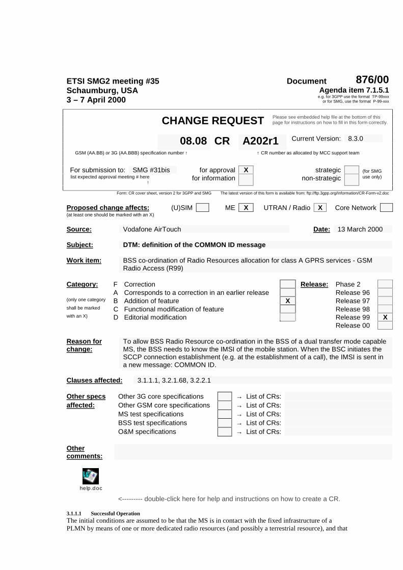
ETSI SMG2 meeting #35 Document 876/00Schaumburg, USA3 – 7 April 2000
Agenda item 7.1.5.1e.g. for 3GPP use the format TP-99xxx
or for SMG, use the format P-99-xxx
CHANGE REQUEST Please see embedded help file at the bottom of thispage for instructions on how to fill in this form correctly.
Current Version: 8.3.008.08 CR A202r1GSM (AA.BB) or 3G (AA.BBB) specification number ↑ ↑ CR number as allocated by MCC support team
For submission to: SMG #31bis for approval X strategic (for SMGlist expected approval meeting # here
↑for information non-strategic use only)
Form: CR cover sheet, version 2 for 3GPP and SMG The latest version of this form is available from: ftp://ftp.3gpp.org/Information/CR-Form-v2.doc
Proposed change affects: (U)SIM ME X UTRAN / Radio X Core Network(at least one should be marked with an X)
Source: Vodafone AirTouch Date: 13 March 2000
Subject: DTM: definition of the COMMON ID message
Work item: BSS co-ordination of Radio Resources allocation for class A GPRS services - GSMRadio Access (R99)
Category: F Correction Release: Phase 2A Corresponds to a correction in an earlier release Release 96
(only one category B Addition of feature X Release 97shall be marked C Functional modification of feature Release 98with an X) D Editorial modification Release 99 X
Release 00
Reason forchange:
To allow BSS Radio Resource co-ordination in the BSS of a dual transfer mode capableMS, the BSS needs to know the IMSI of the mobile station. When the BSC initiates theSCCP connection establishment (e.g. at the establishment of a call), the IMSI is sent ina new message: COMMON ID.
Clauses affected: 3.1.1.1, 3.2.1.68, 3.2.2.1
Other specs Other 3G core specifications → List of CRs:affected: Other GSM core specifications → List of CRs:
MS test specifications → List of CRs:BSS test specifications → List of CRs:O&M specifications → List of CRs:
Othercomments:
help.doc
<--------- double-click here for help and instructions on how to create a CR.
3.1.1.1 Successful OperationThe initial conditions are assumed to be that the MS is in contact with the fixed infrastructure of aPLMN by means of one or more dedicated radio resources (and possibly a terrestrial resource), and that
the MSC has analysed any relevant call control information and wishes to allocate or reallocate to theMS one or more radio resources (and possibly a terrestrial resource).The MSC may send the COMMON ID message to the BSS, containing the IMSI. This message is senton the relevant SCCP connection or it is contained in the SCCP CONNECTION REQUEST message,so that the BSS can associate the IMSI of the mobile station to the used SCCP connection.The MSC is the entity that carries out the necessary analysis on the call control information receivedfrom the MS or fixed network customer.On the basis of this analysis a resource request is made to the appropriate BSS by sending it anASSIGNMENT REQUEST message. This message contains details of the resource(s) required (forinstance channel rate, channel type, data adaption, priority level etc.). If the requested resource(s) is/arefor speech or data it also may indicate the terrestrial circuit that shall be used between the MSC andBSS. The description of the resource(s) can either be a complete specification, or give the BSS somefreedom in the selection (for instance channel rate selection, speech version selection etc.). TheASSIGNMENT REQUEST message may also contain CLASSMARK information in case suchinformation is available in the MSC, but assumed not to be available in the BSS. A full description ofthe message is given in subclause 3.2.1.1.In this specification a "pool" is a group of circuits supporting the same channel types.The ASSIGNMENT REQUEST message is sent via the BSSMAP and is analysed within the BSS.Based on this analysis, which is not defined further in this Technical Specification, the BSS chooses theappropriate radio resource(s) and allocates the appropriate resources for transcoding, rate adaptationetc. On the terrestrial route connecting the BSS and MSC, certain circuits can be used for differentcombinations of bearer capabilities. This can be modelled by grouping the circuits into "pools"supporting the same channel types. The MSC holds this information as route data. If the MSC allocatesan A interface circuit, it should only ever ask for resources from the BSS that it knows are not totallyincompatible with the nominated circuit. The BSS will construct and send the appropriate radioassignment messages, if required (i.e., if the radio resource(s) has/have to be changed), as described inGSM 04.08 and start timer T10. The ASSIGNMENT REQUEST message includes sufficientinformation to allow the BSS to construct the necessary layer 3 radio messages. If the BSS allocates theA interface circuits, and such a circuit is needed, the BSS shall allocate a circuit.In the case where several circuit pools (groups of circuits supporting the same channel types) areavailable on the BSS MSC interface, the terrestrial circuit allocated by the MSC, if any, is chosentaking into account the circuit pool the circuit belongs to and the required channel type.The management of priority levels is implementation dependent, under operator control.If queuing is managed, new requests which cannot be served immediately are put in the queuing fileaccording to the indicated priority levels.The priority levels and the preemption indicators may (singularly or in combination) be used todetermine whether the assignment has to be performed unconditionally and immediately. This wouldlead to triggering of the preemption procedure which may then cause the forced release or forcedhandover of a lower priority connection if no free resource is immediately available.Whilst the process and the extent of the preemption procedure is operator dependent, the preemptionindicators (refer to subclause 3.2.2.18.), if given in the ASSIGNMENT REQUEST, shall be treated ona per connection basis as follows:
- the last received "Preemption Vulnerability indicator" and priority levels shall prevail.
- if the "Preemption Capability indicator" bit is set to 1, then this allocation request can triggerthe running of the preemption procedure.
- if the "Preemption Capability indicator" bit is set to 0, then this allocation request cannottrigger the preemption procedure.
- if the "Preemption Vulnerability" bit is set to 1, then this connection is vulnerable and shallbe included in the preemption process or procedure and as such may be subject to forcedrelease or forced handover.
- if the "Preemption Vulnerability" bit is set to 0, then this connection is not vulnerable topreemption and shall not be included in the preemption process and as such may not besubject to forced release or forced handover.
- if no priority Information Element has been received, both "Preemption Capability" and"Preemption Vulnerability" bits shall be regarded as set to 0.
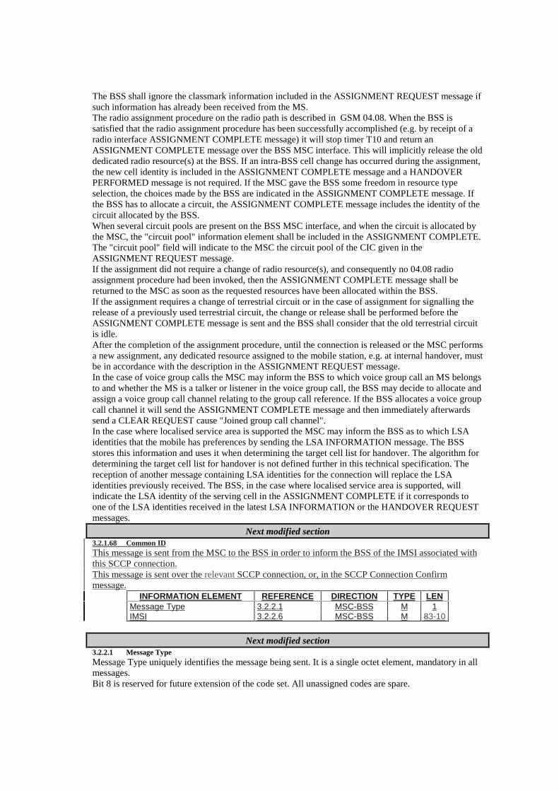
The BSS shall ignore the classmark information included in the ASSIGNMENT REQUEST message ifsuch information has already been received from the MS.The radio assignment procedure on the radio path is described in GSM 04.08. When the BSS issatisfied that the radio assignment procedure has been successfully accomplished (e.g. by receipt of aradio interface ASSIGNMENT COMPLETE message) it will stop timer T10 and return anASSIGNMENT COMPLETE message over the BSS MSC interface. This will implicitly release the olddedicated radio resource(s) at the BSS. If an intra-BSS cell change has occurred during the assignment,the new cell identity is included in the ASSIGNMENT COMPLETE message and a HANDOVERPERFORMED message is not required. If the MSC gave the BSS some freedom in resource typeselection, the choices made by the BSS are indicated in the ASSIGNMENT COMPLETE message. Ifthe BSS has to allocate a circuit, the ASSIGNMENT COMPLETE message includes the identity of thecircuit allocated by the BSS.When several circuit pools are present on the BSS MSC interface, and when the circuit is allocated bythe MSC, the "circuit pool" information element shall be included in the ASSIGNMENT COMPLETE.The "circuit pool" field will indicate to the MSC the circuit pool of the CIC given in theASSIGNMENT REQUEST message.If the assignment did not require a change of radio resource(s), and consequently no 04.08 radioassignment procedure had been invoked, then the ASSIGNMENT COMPLETE message shall bereturned to the MSC as soon as the requested resources have been allocated within the BSS.If the assignment requires a change of terrestrial circuit or in the case of assignment for signalling therelease of a previously used terrestrial circuit, the change or release shall be performed before theASSIGNMENT COMPLETE message is sent and the BSS shall consider that the old terrestrial circuitis idle.After the completion of the assignment procedure, until the connection is released or the MSC performsa new assignment, any dedicated resource assigned to the mobile station, e.g. at internal handover, mustbe in accordance with the description in the ASSIGNMENT REQUEST message.In the case of voice group calls the MSC may inform the BSS to which voice group call an MS belongsto and whether the MS is a talker or listener in the voice group call, the BSS may decide to allocate andassign a voice group call channel relating to the group call reference. If the BSS allocates a voice groupcall channel it will send the ASSIGNMENT COMPLETE message and then immediately afterwardssend a CLEAR REQUEST cause "Joined group call channel".In the case where localised service area is supported the MSC may inform the BSS as to which LSAidentities that the mobile has preferences by sending the LSA INFORMATION message. The BSSstores this information and uses it when determining the target cell list for handover. The algorithm fordetermining the target cell list for handover is not defined further in this technical specification. Thereception of another message containing LSA identities for the connection will replace the LSAidentities previously received. The BSS, in the case where localised service area is supported, willindicate the LSA identity of the serving cell in the ASSIGNMENT COMPLETE if it corresponds toone of the LSA identities received in the latest LSA INFORMATION or the HANDOVER REQUESTmessages.
Next modified section3.2.1.68 Common IDThis message is sent from the MSC to the BSS in order to inform the BSS of the IMSI associated withthis SCCP connection.This message is sent over the relevant SCCP connection, or, in the SCCP Connection Confirmmessage.
INFORMATION ELEMENT REFERENCE DIRECTION TYPE LENMessage Type 3.2.2.1 MSC-BSS M 1IMSI 3.2.2.6 MSC-BSS M 83-10
Next modified section3.2.2.1 Message TypeMessage Type uniquely identifies the message being sent. It is a single octet element, mandatory in allmessages.Bit 8 is reserved for future extension of the code set. All unassigned codes are spare.
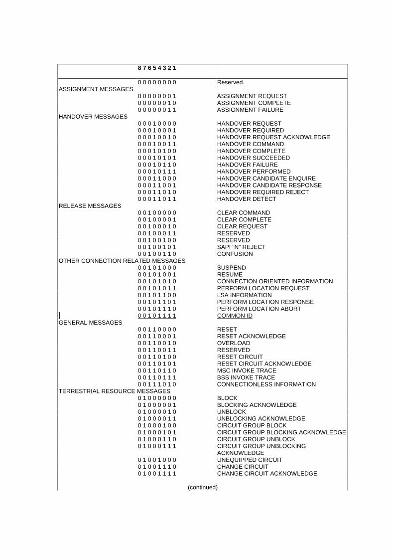
8 7 6 5 4 3 2 1
0 0 0 0 0 0 0 0 Reserved.ASSIGNMENT MESSAGES
0 0 0 0 0 0 0 1 ASSIGNMENT REQUEST0 0 0 0 0 0 1 0 ASSIGNMENT COMPLETE0 0 0 0 0 0 1 1 ASSIGNMENT FAILURE
HANDOVER MESSAGES0 0 0 1 0 0 0 0 HANDOVER REQUEST0 0 0 1 0 0 0 1 HANDOVER REQUIRED0 0 0 1 0 0 1 0 HANDOVER REQUEST ACKNOWLEDGE0 0 0 1 0 0 1 1 HANDOVER COMMAND0 0 0 1 0 1 0 0 HANDOVER COMPLETE0 0 0 1 0 1 0 1 HANDOVER SUCCEEDED0 0 0 1 0 1 1 0 HANDOVER FAILURE0 0 0 1 0 1 1 1 HANDOVER PERFORMED0 0 0 1 1 0 0 0 HANDOVER CANDIDATE ENQUIRE0 0 0 1 1 0 0 1 HANDOVER CANDIDATE RESPONSE0 0 0 1 1 0 1 0 HANDOVER REQUIRED REJECT0 0 0 1 1 0 1 1 HANDOVER DETECT
RELEASE MESSAGES0 0 1 0 0 0 0 0 CLEAR COMMAND0 0 1 0 0 0 0 1 CLEAR COMPLETE0 0 1 0 0 0 1 0 CLEAR REQUEST0 0 1 0 0 0 1 1 RESERVED0 0 1 0 0 1 0 0 RESERVED0 0 1 0 0 1 0 1 SAPI “N” REJECT0 0 1 0 0 1 1 0 CONFUSION
OTHER CONNECTION RELATED MESSAGES0 0 1 0 1 0 0 0 SUSPEND0 0 1 0 1 0 0 1 RESUME0 0 1 0 1 0 1 0 CONNECTION ORIENTED INFORMATION0 0 1 0 1 0 1 1 PERFORM LOCATION REQUEST0 0 1 0 1 1 0 0 LSA INFORMATION0 0 1 0 1 1 0 1 PERFORM LOCATION RESPONSE0 0 1 0 1 1 1 0 PERFORM LOCATION ABORT0 0 1 0 1 1 1 1 COMMON ID
GENERAL MESSAGES0 0 1 1 0 0 0 0 RESET0 0 1 1 0 0 0 1 RESET ACKNOWLEDGE0 0 1 1 0 0 1 0 OVERLOAD0 0 1 1 0 0 1 1 RESERVED0 0 1 1 0 1 0 0 RESET CIRCUIT0 0 1 1 0 1 0 1 RESET CIRCUIT ACKNOWLEDGE0 0 1 1 0 1 1 0 MSC INVOKE TRACE0 0 1 1 0 1 1 1 BSS INVOKE TRACE0 0 1 1 1 0 1 0 CONNECTIONLESS INFORMATION
TERRESTRIAL RESOURCE MESSAGES0 1 0 0 0 0 0 0 BLOCK0 1 0 0 0 0 0 1 BLOCKING ACKNOWLEDGE0 1 0 0 0 0 1 0 UNBLOCK0 1 0 0 0 0 1 1 UNBLOCKING ACKNOWLEDGE0 1 0 0 0 1 0 0 CIRCUIT GROUP BLOCK0 1 0 0 0 1 0 1 CIRCUIT GROUP BLOCKING ACKNOWLEDGE0 1 0 0 0 1 1 0 CIRCUIT GROUP UNBLOCK0 1 0 0 0 1 1 1 CIRCUIT GROUP UNBLOCKING
ACKNOWLEDGE0 1 0 0 1 0 0 0 UNEQUIPPED CIRCUIT0 1 0 0 1 1 1 0 CHANGE CIRCUIT0 1 0 0 1 1 1 1 CHANGE CIRCUIT ACKNOWLEDGE
(continued)
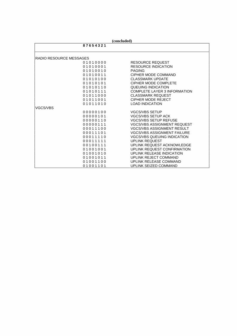
(concluded)8 7 6 5 4 3 2 1
RADIO RESOURCE MESSAGES0 1 0 1 0 0 0 0 RESOURCE REQUEST0 1 0 1 0 0 0 1 RESOURCE INDICATION0 1 0 1 0 0 1 0 PAGING0 1 0 1 0 0 1 1 CIPHER MODE COMMAND0 1 0 1 0 1 0 0 CLASSMARK UPDATE0 1 0 1 0 1 0 1 CIPHER MODE COMPLETE0 1 0 1 0 1 1 0 QUEUING INDICATION0 1 0 1 0 1 1 1 COMPLETE LAYER 3 INFORMATION0 1 0 1 1 0 0 0 CLASSMARK REQUEST0 1 0 1 1 0 0 1 CIPHER MODE REJECT0 1 0 1 1 0 1 0 LOAD INDICATION
VGCS/VBS0 0 0 0 0 1 0 0 VGCS/VBS SETUP0 0 0 0 0 1 0 1 VGCS/VBS SETUP ACK0 0 0 0 0 1 1 0 VGCS/VBS SETUP REFUSE0 0 0 0 0 1 1 1 VGCS/VBS ASSIGNMENT REQUEST0 0 0 1 1 1 0 0 VGCS/VBS ASSIGNMENT RESULT0 0 0 1 1 1 0 1 VGCS/VBS ASSIGNMENT FAILURE0 0 0 1 1 1 1 0 VGCS/VBS QUEUING INDICATION0 0 0 1 1 1 1 1 UPLINK REQUEST0 0 1 0 0 1 1 1 UPLINK REQUEST ACKNOWLEDGE0 1 0 0 1 0 0 1 UPLINK REQUEST CONFIRMATION0 1 0 0 1 0 1 0 UPLINK RELEASE INDICATION0 1 0 0 1 0 1 1 UPLINK REJECT COMMAND0 1 0 0 1 1 0 0 UPLINK RELEASE COMMAND0 1 0 0 1 1 0 1 UPLINK SEIZED COMMAND
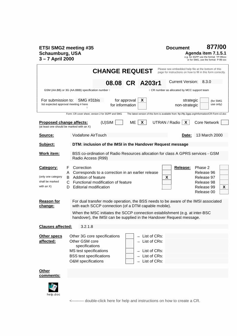
ETSI SMG2 meeting #35 Document 877/00Schaumburg, USA3 – 7 April 2000
Agenda item 7.1.5.1e.g. for 3GPP use the format TP-99xxx
or for SMG, use the format P-99-xxx
CHANGE REQUEST Please see embedded help file at the bottom of thispage for instructions on how to fill in this form correctly.
Current Version: 8.3.008.08 CR A203r1GSM (AA.BB) or 3G (AA.BBB) specification number ↑ ↑ CR number as allocated by MCC support team
For submission to: SMG #31bis for approval X strategic (for SMGlist expected approval meeting # here
↑for information non-strategic use only)
Form: CR cover sheet, version 2 for 3GPP and SMG The latest version of this form is available from: ftp://ftp.3gpp.org/Information/CR-Form-v2.doc
Proposed change affects: (U)SIM ME X UTRAN / Radio X Core Network(at least one should be marked with an X)
Source: Vodafone AirTouch Date: 13 March 2000
Subject: DTM: inclusion of the IMSI in the Handover Request message
Work item: BSS co-ordination of Radio Resources allocation for class A GPRS services - GSMRadio Access (R99)
Category: F Correction Release: Phase 2A Corresponds to a correction in an earlier release Release 96
(only one category B Addition of feature X Release 97shall be marked C Functional modification of feature Release 98with an X) D Editorial modification Release 99 X
Release 00
Reason forchange:
For dual transfer mode operation, the BSS needs to be aware of the IMSI associatedwith each SCCP connection (of a DTM capable mobile).
When the MSC initiates the SCCP connection establishment (e.g. at inter-BSChandover), the IMSI can be supplied in the Handover Request message.
Clauses affected: 3.2.1.8
Other specs Other 3G core specifications → List of CRs:affected: Other GSM core
specifications→ List of CRs:
MS test specifications → List of CRs:BSS test specifications → List of CRs:O&M specifications → List of CRs:
Othercomments:
help.doc
<--------- double-click here for help and instructions on how to create a CR.
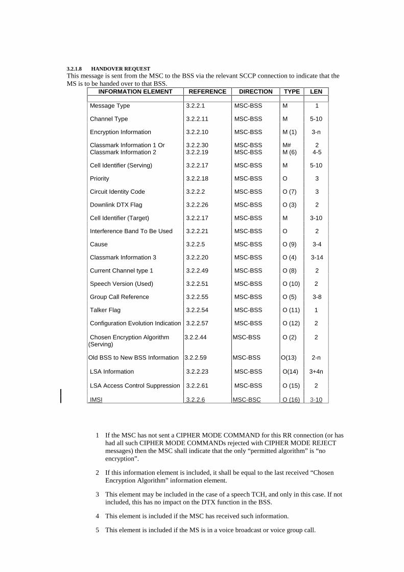
3.2.1.8 HANDOVER REQUESTThis message is sent from the MSC to the BSS via the relevant SCCP connection to indicate that theMS is to be handed over to that BSS.
INFORMATION ELEMENT REFERENCE DIRECTION TYPE LEN
Message Type 3.2.2.1 MSC-BSS M 1
Channel Type 3.2.2.11 MSC-BSS M 5-10
Encryption Information 3.2.2.10 MSC-BSS M (1) 3-n
Classmark Information 1 Or 3.2.2.30 MSC-BSS M# 2 Classmark Information 2 3.2.2.19 MSC-BSS M (6) 4-5
Cell Identifier (Serving) 3.2.2.17 MSC-BSS M 5-10
Priority 3.2.2.18 MSC-BSS O 3
Circuit Identity Code 3.2.2.2 MSC-BSS O (7) 3
Downlink DTX Flag 3.2.2.26 MSC-BSS O (3) 2
Cell Identifier (Target) 3.2.2.17 MSC-BSS M 3-10
Interference Band To Be Used 3.2.2.21 MSC-BSS O 2
Cause 3.2.2.5 MSC-BSS O (9) 3-4
Classmark Information 3 3.2.2.20 MSC-BSS O (4) 3-14
Current Channel type 1 3.2.2.49 MSC-BSS O (8) 2
Speech Version (Used) 3.2.2.51 MSC-BSS O (10) 2
Group Call Reference 3.2.2.55 MSC-BSS O (5) 3-8
Talker Flag 3.2.2.54 MSC-BSS O (11) 1
Configuration Evolution Indication 3.2.2.57 MSC-BSS O (12) 2
Chosen Encryption Algorithm(Serving)
3.2.2.44 MSC-BSS O (2) 2
Old BSS to New BSS Information 3.2.2.59 MSC-BSS O(13) 2-n
LSA Information 3.2.2.23 MSC-BSS O(14) 3+4n
LSA Access Control Suppression 3.2.2.61 MSC-BSS O (15) 2
IMSI 3.2.2.6 MSC-BSC O (16) 3-10
1 If the MSC has not sent a CIPHER MODE COMMAND for this RR connection (or hashad all such CIPHER MODE COMMANDs rejected with CIPHER MODE REJECTmessages) then the MSC shall indicate that the only “permitted algorithm” is “noencryption”.
2 If this information element is included, it shall be equal to the last received “ChosenEncryption Algorithm” information element.
3 This element may be included in the case of a speech TCH, and only in this case. If notincluded, this has no impact on the DTX function in the BSS.
4 This element is included if the MSC has received such information.
5 This element is included if the MS is in a voice broadcast or voice group call.
6 One of these two elements is sent.
7 This element is included when the channel type Information Element indicates speech ordata, and only in those cases. In case of Voice Group Call talker handover, this elementmay contain the Circuit Identity Code already allocated during the VBS/VGCSassignment procedure, meaning that the already allocated terrestrial resource of the newcell is used.
8 This element is included at least when the message is sent as a reaction to reception of aHANDOVER REQUIRED message containing a “Current channel type 1” informationelement. In this case it shall be equal to the received element.
9 This information element should always be included. Its cause value should be the sameas indicated in the corresponding Handover Required message.
10 This element is included at least when the message is sent as a reaction to reception of aHANDOVER REQUIRED message containing a “Speech version (used)” informationelement. In this case it shall be equal to the received element.
11 This information element is included for voice group call, when this is included itindicates that the mobile is a talker in the call else the mobile is a listener.
12 The information is indicated by the MSC if known
13 This element is included if and only if the message is sent as a reaction to the receptionof a HANDOVER REQUIRED message containing an “old BSS to new BSSinformation” information element. Its contents shall be equal to the received element.
14 This information element is included when the subscriber has localised service areasupport.
15 This information element is included if LSA access control function shall be suppressedin the BSS.
Typical Cause values are:uplink quality,uplink strength,downlink quality,downlink strengthdistance,better cell,response to MSC invocationO and M intervention,directed retry,switch circuit pool,traffic,preemption.
16 This information element is included at least when the MS is dual transfer mode capable.
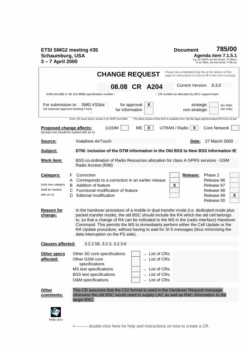
ETSI SMG2 meeting #35 Document 785/00Schaumburg, USA3 – 7 April 2000
Agenda item 7.1.5.1e.g. for 3GPP use the format TP-99xxx
or for SMG, use the format P-99-xxx
CHANGE REQUEST Please see embedded help file at the bottom of thispage for instructions on how to fill in this form correctly.
Current Version: 8.3.008.08 CR A204GSM (AA.BB) or 3G (AA.BBB) specification number ↑ ↑ CR number as allocated by MCC support team
For submission to: SMG #31bis for approval X strategic (for SMGlist expected approval meeting # here
↑for information non-strategic use only)
Form: CR cover sheet, version 2 for 3GPP and SMG The latest version of this form is available from: ftp://ftp.3gpp.org/Information/CR-Form-v2.doc
Proposed change affects: (U)SIM ME X UTRAN / Radio X Core Network(at least one should be marked with an X)
Source: Vodafone AirTouch Date: 27 March 2000
Subject: DTM: inclusion of the DTM information in the Old BSS to New BSS Information IE
Work item: BSS co-ordination of Radio Resources allocation for class A GPRS services - GSMRadio Access (R99)
Category: F Correction Release: Phase 2A Corresponds to a correction in an earlier release Release 96
(only one category B Addition of feature X Release 97shall be marked C Functional modification of feature Release 98with an X) D Editorial modification Release 99 X
Release 00
Reason forchange:
In the handover procedure of a mobile in dual transfer mode (i.e. dedicated mode pluspacket transfer mode), the old BSC should include the RA which the old cell belongsto, so that a change of RA can be indicated to the MS in the (radio interface) HandoverCommand. This permits the MS to immediately perform either the Cell Update or theRA Update procedure, without having to wait for SI 6 messages (thus minimising thedata interruption on the PS side).
Clauses affected: 3.2.2.58, 3.2.3, 3.2.3.6
Other specs Other 3G core specifications → List of CRs:affected: Other GSM core
specifications→ List of CRs:
MS test specifications → List of CRs:BSS test specifications → List of CRs:O&M specifications → List of CRs:
Othercomments:
This CR assumes that the CGI format is used in the Handover Request message:otherwise the old BSC would need to supply LAC as well as RAC information to thetarget BSC.
help.doc
<--------- double-click here for help and instructions on how to create a CR.
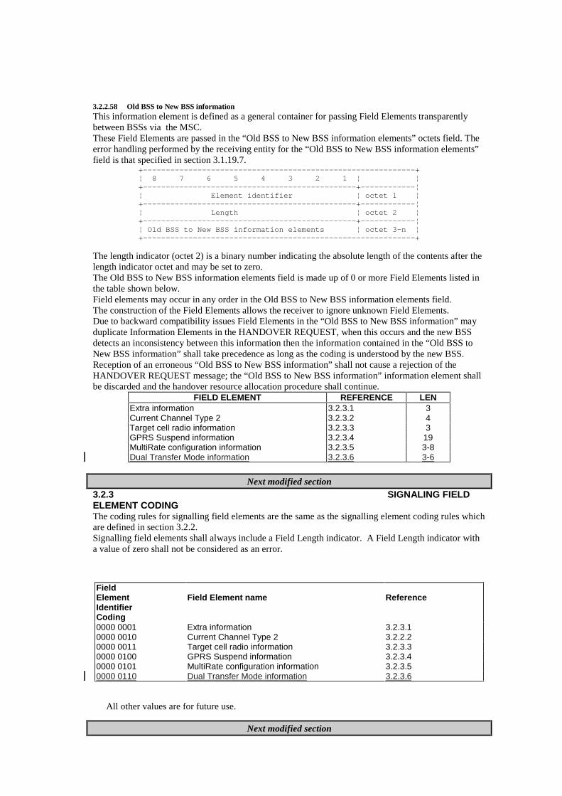
3.2.2.58 Old BSS to New BSS informationThis information element is defined as a general container for passing Field Elements transparentlybetween BSSs via the MSC.These Field Elements are passed in the “Old BSS to New BSS information elements” octets field. Theerror handling performed by the receiving entity for the “Old BSS to New BSS information elements”field is that specified in section 3.1.19.7.
+------------------------------------------------------------+¦ 8 7 6 5 4 3 2 1 ¦ ¦+-----------------------------------------------+------------¦¦ Element identifier ¦ octet 1 ¦+-----------------------------------------------+------------¦¦ Length ¦ octet 2 ¦+-----------------------------------------------+------------¦¦ Old BSS to New BSS information elements ¦ octet 3-n ¦+------------------------------------------------------------+
The length indicator (octet 2) is a binary number indicating the absolute length of the contents after thelength indicator octet and may be set to zero.The Old BSS to New BSS information elements field is made up of 0 or more Field Elements listed inthe table shown below.Field elements may occur in any order in the Old BSS to New BSS information elements field.The construction of the Field Elements allows the receiver to ignore unknown Field Elements.Due to backward compatibility issues Field Elements in the “Old BSS to New BSS information” mayduplicate Information Elements in the HANDOVER REQUEST, when this occurs and the new BSSdetects an inconsistency between this information then the information contained in the “Old BSS toNew BSS information” shall take precedence as long as the coding is understood by the new BSS.Reception of an erroneous “Old BSS to New BSS information” shall not cause a rejection of theHANDOVER REQUEST message; the “Old BSS to New BSS information” information element shallbe discarded and the handover resource allocation procedure shall continue.
FIELD ELEMENT REFERENCE LENExtra information 3.2.3.1 3Current Channel Type 2 3.2.3.2 4Target cell radio information 3.2.3.3 3GPRS Suspend information 3.2.3.4 19MultiRate configuration information 3.2.3.5 3-8Dual Transfer Mode information 3.2.3.6 3-6
Next modified section3.2.3 SIGNALING FIELDELEMENT CODINGThe coding rules for signalling field elements are the same as the signalling element coding rules whichare defined in section 3.2.2.Signalling field elements shall always include a Field Length indicator. A Field Length indicator witha value of zero shall not be considered as an error.
FieldElementIdentifierCoding
Field Element name Reference
0000 0001 Extra information 3.2.3.10000 0010 Current Channel Type 2 3.2.2.20000 0011 Target cell radio information 3.2.3.30000 0100 GPRS Suspend information 3.2.3.40000 0101 MultiRate configuration information 3.2.3.50000 0110 Dual Transfer Mode information 3.2.3.6
All other values are for future use.
Next modified section
3.2.3.6 Dual Transfer Mode informationThis Field Element contains information about the PS domain of a mobile in dual transfer mode. TheCS information is contained in the Current Channel Type 2 Field Element.It is coded as follows:
Àªªªªª¨ªªªªª¨ªªªªª¨ªªªªª¨ªªªªª¨ªªªªª¨ªªªªª¨ªªªªª¨ªª
ªªªªªªªªªª¥
�����������������������������������������������
���������������
©ªªªªª§ªªªªª§ªªªªª§ªªªªª§ªªªªª§ªªªªª§ªªªªª§ªªªªª«ªª
ªªªªªªªªªª�
����������������(zL�L���PKL��PMPL���������������
���J�L��������
©ªªªªªªªªªªªªªªªªªªªªªªª¨ªªªªªªªªªªªªªªªªªªªªªªª«ªª
ªªªªªªªªªª�
���������������������/L�N�O�������������������
�����J�L��������
©ªªªªªªªªªªªªªªªªªªªªªªª¨ªªªªªªªªªªªªªªªªªªªªªªª«ªª
ªªªªªªªªªª�
����������������������������������������������
�����J�L��������
©ªªªªªªªªªªªªªªªªªªªªªªª¨ªªªªªªªªªªªªªªªªªªªªªªª«ªª
ªªªªªªªªªª�
���������������������5$&�/$&�������������������
����J�L��������
¦ªªªªªªªªªªªªªªªªªªªªªªª§ªªªªªªªªªªªªªªªªªªªªªªª§ªª
ªªªªªªªªªª¿
Octet 3 is coded as follows:Àªªªªª¨ªªªªª¨ªªªªª¨ªªªªª¨ªªªªª¨ªªªªª¨ªªªªª¨ªªªªª¨ªª
ªªªªªªªªªª¥
�����������������������������������������������
���������������
©ªªªªª«ªªªªª«ªªªªª«ªªªªª«ªªªªª«ªªªªª«ªªªªª«ªªªªª«ªª
ªªªªªªªªªª�
�5$�P�M���H�����������������6�H�L���������������
���J�L��������
¦ªªªªª§ªªªªª§ªªªªª§ªªªªª§ªªªªª§ªªªªª§ªªªªª§ªªªªª§ªª
ªªªªªªªªªª¿
Bits 8 and 7 are the RA information indicator. It is coded as follows:Bit 8 7
0 0 Octets 4-6 are not present0 1 Octet 4 contains the RAC of the serving cell1 0 Not sent; if received, interpret as ‘00’1 1 Octet 4 contains the RAC of the serving cell. Octets 5-6 contain the LAC of theserving cell
Bits 6 to 1 are spare.
Octets 4-6 are present or not depending upon bits 8-7 of octet 3. If present, octet 4 contains the RAC ofthe serving cell. If present, octets 5-6 contain the LAC of the serving cell.

![IS ARTICLE 31BIS ENOUGH - Temple University · 2008] IS ARTICLE 31BIS ENOUGH? 163 export medications to developing countries.16 While Article 31bis seeks to assist developing countries](https://img.pdfslide.us/doc/110x75/5af2ba567f8b9ac246910e87/is-article-31bis-enough-temple-is-article-31bis-enough-163-export-medications.jpg)