Embed Size (px)
Citation preview

Page 1
ETSI STC SMG2 #23 TDoc SMG 638/97Meeting #23Budapest, Hungary, 13th - 17th October 1997
Source : SMG2
Title :
CRs for GPRS on GSM 03.64, SMG2 WPA, Release 97, Non-Strategic
Proposed Agenda Item : 6.1Presented for : Approval
Introduction :
This document contains Phase 2+ (Release ‘97) Change Requests to support theGPRS work item, on GSM 03.64. They have been agreed by SMG2, and are proposedfor approval by SMG#23. The CRs are considered as non-strategic as they are notproposed to be presented.
The change requests are independent and can be dealt with separately.
SMG2TDOC
SPEC VERS CR Rv SUBJECT CAT STC_MEET
264/97 03.64 5.0.0 A022 1 CR 03.64 A022r1 Unacknowledgedmode of RLC/MAC operation
B Sept 97
264/97 03.64 5.0.0 A023 1 CR 03.64 A023r1 Improved RLC ServicePrimitives
C Sept 97
264/97 03.64 5.0.0 A026 1 CR to 03.64 A026r1 Optimisation fornetwork control cell reselection
B Sept 97
264/97 03.64 5.0.0 A027 2 CR 0364 A027r2 Abnormal Cases in GPRSMS Ready State: Leaky BucketProcedure
C Sept 97
264/97 03.64 5.0.0 A030 1 CR 0364 A030r1 Abnormal Cases in GPRSMS Ready State
C Sept 97
Other Comments:
Number of pages:

Page 2
Blank page

ETSI/STC SMG2 WPB part of Tdoc SMG2 WPB_018/97Edinburgh, UK (reprint of Tdoc SMG2/3 WPA 97A217)22-26 September, 1997
CHANGE REQUEST No. A022 rev1
Technical Specification GSM 03.64 version 5.0.0
Submitted to SMG for approval without presentation ("non-strategic") [ ]
with presentation ("strategic") [ ]
Status at SMG [ ]: Approved [ ] Rejected [ ] Postponed [ ]
Phase 1: [ ] Phase 2: [ ] Phase 2+: [Release 97] Work item: GPRS
Other phase(s) affected: [ ] If yes, linked CR(s):
Proposed change affects: SIM [ ] ME [X] Network [X]
Source: SMG2 WPA Date: 21 August 1997
Subject: The definition of unacknowledged mode for RLC/MAC operation
Category: F - Correction [ ]A - Corresponds to a Phase 2 correction [ ]B - Addition of Feature [x]C - Functional modification of Feature [ ]D - Editorial modification [..]
Reason for change:
The unacknowledged mode for RLC/MAC operation is not adequately described in GSM 03.64.
Sections affected, and additional explanation of details of change (if needed):
Subclauses:6.6.4.3 new title6.6.4.4 new subclause6.6.4.4.2.1. minor modification6.6.4.5.2. minor modification
Attached revised pages:
Page(s):
If other core Specifications are affected, necessary (and attached) Joint CRs:
Affects(possibly):
MS Test Specifications [ ] BSS Test Specifications [ ] O&M Specifications [ ]
Attached CRs?:
Cross Phase Compatibility:
Change affects operation of: Phase 1 MS in Phase 2(+) NW [ ] Phase 2(+) MS in Phase 1 NW [ ]
Change affects operation of: Phase 1 SIM in Phase 2(+) ME[ ] Phase 2(+) SIM in Phase 1 ME [ ]
Other comments:

6.6.4 Model of Operation
Each PDCH is a shared medium between multiple MSs and the Network. Direct communication ispossible only between an MS and the Network.
The GPRS radio interface consists of asymmetric and independent uplink and downlink channels. Thedownlink carries transmissions from the Network to multiple MSs and does not require contentionarbitration. The uplink is shared among multiple MSs and requires contention control procedures.
The allocation of radio resources by the PLMN and the use of these resources by the MSs can be brokendown into two parts:
- The PLMN allocates radio resources for the GPRS (uplink and downlink) in a symmetric manner.- The allocated uplink and downlink radio resources for point-to-point, point-to-multipoint multicast or
group call service types are used independently of each other. Dependent allocation of uplink anddownlink shall be possible, in order to allow simple MSs to transfer data simultaneously in bothdirections. Allocation of several PDTCHs for one MS is possible.
The access to the GPRS uplink uses a Slotted-Aloha based reservation protocol. The Access Burstspecified in GSM 05.01 [3] is used. The Packet Channel Request sent by an MS is responded by aPacket Immediate Assignment message indicating the uplink resources reserved for the MS.
The Network Protocol Data Units (N-PDU) are segmented into the Subnetwork Protocol Data Units (SN-PDU) by the Subnetwork Dependent Convergence (SNDC) protocol and SN-PDUs are encapsulated intoone or several LLC frames. LLC frames are of variable length. The maximum size of the LLC frameinformation (excluding LLC headers) is 1600 octets. See GSM 03.60 [2] for information on SNDC andLLC. The details on SNDC can be found in GSM 04.65 [11] and the details on LLC can be found in GSM04.64 [12]. LLC frames are segmented into RLC Data Blocks. At the RLC/MAC layer, a selective ARQprotocol (including block numbering) between the MS and the Network provides retransmission oferroneous RLC Data Blocks. When a complete LLC frame is successfully transferred across the RLClayer, it is forwarded to the LLC layer.
BH
FH
LLC layer
RLC/MAC layer
Physical layer
Information field FCS
Normal burst Normal burst Normal burst Normal burst
Info fieldBH BCSRLCblocks
LLC frame
Primaryblock
Followingblock
Info field BCS Info field BH BCS
FH = Frame HeaderFCS = Frame Check SequenceBH = Block HeaderBCS= Block Check Sequence
(When SDCCH coding is used, BCS corresponds to the Fire code)
Figure 1: Transmission and reception data flow
6.6.4.1 Uplink State Flag
The Uplink State Flag (USF) is used on PDCH to allow multiplexing of Radio blocks from a number ofMSs.

When the SDCCH coding scheme is used, the USF comprises 3 bits at the beginning of each Radio Blockthat is sent on the downlink. It enables the coding of 8 different USF states which are used to multiplex theuplink traffic.
On PCCCH, one USF value is used to denote PRACH (USF=FREE). The other USF valuesUSF=R1/R2/...R7 are used to reserve the uplink for different MSs. On PDCHs not carrying PCCCH, theeight USF values USF=R1/R2/.../R8 are used to reserve the uplink for different MSs. One USF value shallbe used to prevent collision on uplink channel, when MS without USF is using uplink channel. The USFpoints to the next uplink Radio Block.
The MS shall send the Packet Channel Request in one of the four bursts on the Radio Block used forPRACH (indicated by setting USF=FREE). In the access, the burst is selected randomly.
6.6.4.2 Temporary Flow Identity
The method of implementing the selective ARQ protocol on the RLC level includes the assignment of aTemporary Flow Identity (TFI) to each Temporary Block Flow (TBF) transmitted to/from an MS. One TBFmay comprise a number of LLC frames. The assigned TFI is unique among concurrent LLC frametransfer sequences in a cell and is used instead of the MS identity in the RLC/MAC layer. The TFI isassigned in a resource assignment message that precedes the transfer of LLC frames belonging to oneTBF to/from the MS. The same TFI is included in every RLC header belonging to a particular TBF as wellas in the control messages associated to the LLC frame transfer (e.g. acknowledgements) in order toaddress the peer RLC entities. The length of TFI is 7 bits.
6.6.4.3 Acknowledged mode for RLC/MAC operationSelective ARQ Operation
The transfer of RLC Data Blocks in the acknowledged RLC/MAC mode is controlled by a selective ARQmechanism coupled with the modulo-128 numbering of the RLC Data Blocks within one Temporary BlockFlow. The sending side (the MS or the network) transmits blocks within a window of 64 blocks and thereceiving side periodically sends temporary Packet Ack/Nack message. Every such messageacknowledges all correctly received RLC Data Blocks up to an indicated block number, thus “moving” thebeginning of the sending window on the sending side. Additionally, the bitmap that starts at the same RLCData Block is used to selectively request erroneously received RLC Data Blocks for retransmission. Thesending side then retransmits the erroneous RLC Data Blocks, eventually resulting in further sliding thesending window. The temporary Packet Ack/Nack message does not include any change in the currentassignment (and thus does not have to be acknowledged when sent on downlink). A missing temporaryPacket Ack/Nack is not critical and a new one can be issued whenever.
When receiving uplink data from a MS the network shall maintain a count of the number of erroneousblocks received from the MS and allocate additional resources automatically. The allocation may becommunicated in a packet Ack/Nack or an unsolicited resource assignment on the PACCH.
6.6.4.4 Unacknowledged mode for RLC/MAC operation
The transfer of RLC Data Blocks in the unacknowledged RLC/MAC mode is controlled by the modulo-128numbering of the RLC Data Blocks within one Temporary Block Flow and does not include anyretransmissions. The receiving side extracts user data from the received RLC Data Blocks and attemptsto preserve the user information length by replacing missing RLC Data Blocks by dummy information bits.
The same mechanism and message format for sending temporary acknowledgment messages is used asfor acknowledged mode in order to convey the necessary control signalling (e.g. monitoring of channelquality for downlink channel or timing advance correction for uplink transfers). The fields for denoting theerroneous RLC blocks may be used as an additional measure for channel quality (i.e. parameter for linkadaptation). The sending side (the MS or the network) transmits a number of radio blocks (e.g. 64 blocks)and then polls the receiving side to send a temporary Packet Ack/Nack message. Further, the transfer ofdata does not even have to be interrupted when receiving such temporary Ack/Nack message if the MS iscapable of sending and receiving in the same TDMA frames for that particular channel assignment. Thetemporary Packet Ack/Nack message does not include any change in the current assignment. A missingtemporary Packet Ack/Nack is not critical and a new one can be obtained whenever.

6.6.4.5 Mobile Originated Packet Transfer
6.6.4.5.1 Uplink Access
MS Network
Packet Channel Request
Packet Immediate Assignment
Packet Resource Request
Packet Resource Assignment
PRACH or RACH
PAGCH or AGCH
PACCH
PACCH
(Optional)
(Optional)
Figure 2: Access and allocation for the one or two phase packet access, uplink packet transfer
An MS initiates a packet transfer by making a Packet Channel Request on PRACH or RACH. The networkresponds on PAGCH or AGCH respectively. It is possible to use one or two phase packet access method(see Figure 2).
In the one phase access, the Packet Channel Request is responded by the network with the PacketImmediate Assignment reserving the resources on PDCH(s) for uplink transfer of a number of Radioblocks. The reservation is done accordingly to the information about the requested resources that iscomprised in the Packet Channel Request. On RACH, there is only one cause value available for denotingGPRS and the network can assign uplink resources on 1 or 2 PDCHs. On PRACH, the Packet ChannelRequest may contain more adequate information about the requested resources and, consequently,uplink resources on one or several PDCHs can be assigned by using the Packet Immediate Assignmentmessage.
In the two phase access, the Packet Channel Request is responded with the Packet ImmediateAssignment which reserves the uplink resources for transmitting the Packet Resource Request. ThePacket Resource Request message carries the complete description of the requested resources for theuplink transfer. Thereafter, the network responds with the Packet Resource Assignment reservingresources for the uplink transfer.
There is also a case where the network side, in the Packet Immediate Assignment, reserves uplinkresources for transmission of a number of Radio blocks (i.e. one phase access) but the MS is not satisfiedwith the assigned resources (e.g. only on 1 time slot). In such case, the MS can override the one stepaccess by sending the Packet Resource Request on the assigned resource (i.e. MS initiated two phaseaccess).
The Packet Immediate Assignment and the Packet Resource Assignment messages include TimingAdvance (TA) and Power Control (PC) information.
If there is no response to the Packet Channel Request within predefined time period, the MS makes aretry after a random backoff time.
On PRACH there is used a 2-step approach including a long-term and a short-term estimation of thepersistence (see Figure 10). The optimal persistence of the mobile stations is calculated at the networkside.

accesscontrol
decoding ofparameters
persistence control
short-termestimation
accessanalysis
long-termestimation
persistenceinstruction
set P
contentionlevelsρ(i)
access(priority i)
networkside
mobilestation
Figure 3: Basic principle of random access traffic control
The actual persistence values depend on:
- the priority i of the packet to be transmitted
- the amount of traffic within higher priority classes
- the amount of traffic within the own priority class
The short-term estimation indicates the contention level ρ, which comprises 4 classes (1, 2, 3 and 4). Thevalues of the actual contention level ρ(i) for each priority i (i = 1..4), where priority 1 represents the highestpriority, are broadcast on the PBCCH.
The long-term estimation is realized as a set of access parameters kij for all priorities i and contentionlevels ρ(i) and is broadcast only occasionally on the PBCCH to the MS.
In the MS a function is predefined to decode the received access parameters. It results a value π(ρ(i)),which is used to calculate the access probability of the given priority:
π(ρ(i)) = 1/2^kij for kij ≠ 15(6)
π(ρ(i)) = 0 for kij = 15
The access probability p(i) for the priority i is calculated as follows:
i
p(i) = Π π(ρ(k))(7)
k=1
The resulting access probability p(i) is compared with a generated random number r=1/2^k,k=rand[0...15] (k∈ N). If p(i)>r, the MS is allowed to send the random access. The determination of numberof slots belonging to the MS’s PRACH between two successive Packet Channel Request messages(excluding the slots containing the messages themselves) is defined in GSM 04.08. If p(i)<r, the MSsuppresses the sending of the random access and restarts the backoff procedure.
Optionally, the existing backoff algorithm on RACH can be used on PRACH.
On RACH, the existing backoff algorithm shall be used.
Occasionally, more Packet Channel Requests can be received than can be served. To handle this, aPacket Queuing Notification is transmitted to the sender of the Packet Channel Request. The notificationincludes information that the Packet Channel Request message is correctly received and PacketImmediate Assignment may be transmitted later. Packet Queuing Notification can be concatenated withthe Packet Immediate Assignment to another MS in the same downlink Radio Block. If the Timing

Advance information becomes inaccurate for an MS, the Packet Polling can be used to estimate the newTiming Advance before issuing the Packet Immediate Assignment.
6.6.4.5.2 Dynamic allocation
6.6.4.5.2.1 Uplink Packet TransferThe Packet Immediate Assignment message includes the list of PDCHs and the corresponding USF valueper PDCH. A unique TFI is allocated and is thereafter included in each RLC Data and Control Blockrelated to that Temporary Block Flow. The MS monitors the USFs on the allocated PDCHs and transmitsRadio blocks on those which currently bear the USF value reserved for the usage of the MS.
Because each Radio Block includes an identifier (TFI), all received Radio blocks are correctly associatedwith a particular LLC frame and a particular MS, thus making the protocol highly robust. By altering thestate of USF, different PDCHs can be "opened" and "closed" dynamically for certain MSs thus providing aflexible reservation mechanism. Additionally, packets with higher priority and pending control messagescan temporarily interrupt a data transmission from one MS.
The channel reservation algorithm can also be implemented on assignment basis. This allows individualMSs to transmit a predetermined amount of time without interruptions.
The MS may be allowed to use the uplink resources as long as there is queued data on the RLC/MAClayer to be sent from the MS. It can comprise a number of LLC frames. In that sense the radio resourcesare assigned on the initially “unlimited” time basis. Alternatively, the uplink assignment for eachassignment may be limited to a number of radio blocks (e.g. in order to offer more fair access to themedium at higher loads).
The selective ARQ operation for the acknowledged RLC/MAC mode is described in Ssubclause 6.6.4.3.The acknowledgement procedure of the LLC layer is not combined with the acknowledgement procedureon the underlying RLC/MAC layer. The unacknowledged RLC/MAC mode operation is described inSubclause 6.6.4.4.
Figure 4 shows an example of message sequence for the (multislot) uplink data transfer with oneresource reassignment and possible RLC Data Block re-transmissions.

Data Block
temporary Packet Ack/Nack
Data Block (last)
Access and Assignment
MS Network
PDTCH
PACCH
PDTCH
Packet Resource Reassignment
Packet Resource Reassignment Ack
PACCH
PACCH
Data BlockPDTCH
Data BlockPDTCH
Data Block (last in send window)PDTCH
Data BlockPDTCH
Data BlockPDTCH
Data BlockPDTCH
Data BlockPDTCH
final Packet Ack/Nack PACCH
Figure 4: An example of dynamic allocation uplink data transfer
6.6.4.5.2.2 Release of the ResourcesThe release of the resources is normally initiated from the MS by indicating the last RLC Data Block to besent (or alternatively to countdown the last couple of blocks).
Further, the premature release or change of assignment for one MS can be initiated by the network. In thecase of release, the MS is ordered to interrupt the Temporary Block Flow and back-off. The MS shall thenreorganize the uplink buffer and issue a new Packet Channel Request to continue the uplink transfer withthe RLC Data Blocks containing untransferred (i.e. on the RLC/MAC layer unacknowledged) LLC frames.In the case of the change in assignment, the Packet Resource Reassignment message is issued. The MSacknowledges the Packet Resource Reassignment message in an immediate reserved block period onthe uplink. Upon correct reception of the Packet Resource Reassignment Ack, the old resources may bereused (i.e. USFs).
The normal release of resources for RLC connection carrying a mobile originated packet transfer, themechanism based on acknowledged final Packet Ack/Nack combined with timers is used.
After the MS has sent its last RLC Data Block (indicated by the countdown field), the acknowledgement isexpected from the network side. By sending the last block, the MS may no longer use the sameassignment unless a negative acknowledgement arrives. It also means that the network side mayreallocate the same USF(s) to some other user as soon as all the RLC Data Blocks belonging to thatTemporary Block Flow are correctly received; that regardless of the possible later errors in theacknowledgements.
The next step, in the case of all RLC Data Blocks being correctly received, is that the network sendsPacket Ack/Nack which is to be immediately acknowledged in the reserved uplink block period. It must bepossible for the network not to use the mechanism of acknowledgement for Packet Ack/Nack in whichcase the release of the resources procedure relies only on timers. The TFI can be reused for anotherassignment either upon the reception of the acknowledgement for Packet Ack/Nack or after expiry of theguard timer.

6.6.4.5.3 Contention Resolution
Contention resolution is an important part of RLC/MAC protocol operation, especially because onechannel allocation can be used to transfer a number of LLC frames.
There are two basic access possibilities, one phase and two phase access as defined in Section 6.6.4.4.1.
The two phase access is inherently immune for possibility that two MSs can perceive the same channelallocation as their own. Namely the second access phase, the Packet Resource Request, uniquelyidentifies the MS by its TLLI. The same TLLI is included in the Packet Resource Assignment and nomistake is possible.
The one phase access is somewhat insecure and an efficient contention resolution mechanism has to beintroduced.
The first part of the solution is the identification of the MS. The presentation of sending MS on theRLC/MAC level is necessary not only for contention resolution but also to be able to establish RLCprotocol entity for that Temporary Block Flow on the network side. Additionally, the TLLI is necessary to beable to match simultaneous uplink and downlink packet transfers by taking into consideration multislotcapability of that MS.
In order to uniquely identify the MS when sending on uplink, the RLC Header for the first RLC Data Blockon uplink is extended to include the TLLI. The biggest disadvantage of this method is that the TLLI is alsoincluded in the LLC Frame Header so that this may seem as unnecessary overhead.
The second part of the solution is the notification from the network side about who owns the allocation.That is solved by the inclusion of the TLLI in the temporary Packet Ack/Nack. This message can be sentin an early stage, even before the receive window for RLC/MAC protocol operation is full. By doing so, thecontention is resolved after the first occurrence of Packet Ack/Nack. The possibility of RLC Data Blocksbeing captured from “wrong” MS, thus destroying the LLC frame, shall be covered for by retransmissionson the LLC layer.
6.6.4.5.4 Fixed Allocation
Fixed allocation uses the Packet Fixed Immediate Assignment or Packet Fixed Resource Assignmentmessage to communicate a detailed fixed uplink resource allocation to the MS. The fixed allocationconsists of a start frame, slot assignment, and block assignment bitmap representing the assigned blocksper timeslot. The MS waits until the start frame indicated and then transmits radio blocks on those blocksindicated in the block assignment bitmap. A MS receiving this allocation is free to transmit on the uplinkwithout monitoring the downlink for the USF. If the current allocation is not sufficient, the MS may requestadditional resources in one of the assigned uplink blocks. A unique TFI is allocated and is thereafterincluded in each RLC data and control block related to that Temporary Block Flow. Because each RadioBlock includes an identifier (TFI), all received Radio blocks are correctly associated with a particular LLCframe and a particular MS.
The number of blocks an MS requests in the initial and subsequent allocation request messages shall onlyaccount for the number of data and control blocks it intends to send. The MS shall not request additionalblocks for the retransmission of erroneous blocks.
The selective ARQ operation for the acknowledged RLC/MAC mode is described in SubclauseChapter6.6.4.3. The acknowledgement procedure of the LLC layer will not be combined with theacknowledgement procedure on the underlying RLC/MAC layer. The unacknowledged RLC/MAC modeoperation is described in Subclause 6.6.4.4.
Figure 12 shows an example of message sequence for the (multislot) uplink data transfer with oneresource reassignment and possible RLC Data Block re-transmissions.

Data Block
temporary Packet Ack/Nack
Data Block (last)
Access and Assignment
PDTCH
PACCH
PDTCH
Packet Fixed Resource Reassignment
Packet Resource Reassignment AckPACCH
PACCH
Data Block PDTCH
Data Block PDTCH
Data Block PDTCH
Data BlockPDTCH
Data BlockPDTCH
Data BlockPDTCH
Data BlockPDTCH
final Packet Ack/Nack PACCH
Figure 5: An example of fixed allocation uplink data transfer
6.6.4.6 Mobile Terminated Packet Transfer
6.6.4.6.1 Packet Paging
The Network initiates packet transfer to an MS that is in Standby state by sending a Packet PagingRequest on the downlink PPCH or PCH. The MS responds to the Packet Paging Request by initiating aprocedure for page response. The RLC/MAC Packet Paging Response message contains TLLI, as wellas a complete LLC frame including also TLLI (see Figure 6). The message sequence described in thefigure below is conveyed either on PCCCH or on CCCH. After the Packet Paging Response, the mobilitymanagement state of the MS is Ready.
MS Network
Packet Channel Request
Packet Immediate Assignment
Packet Paging Response (LLC frame)
PRACH or RACH
PAGCH or AGCH
PACCH
PPCH or PCHPacket Paging Request
Figure 6: Paging message sequence for Paging, downlink packet transfer.
The paging procedure is followed by the Packet Resource Assignment (Figure 14) and packet transferprocedures (Figure 15).

MS Network
Packet Resource AssignmentPACCH orPAGCH orAGCH
Figure 7: Downlink PDTCH Assignment in GPRS Ready state using Packet Resource Assignmentmessage.
6.6.4.6.2 Downlink Packet Transfer
Transmission of a packet to an MS in the Ready state is initiated by the Network using the PacketResource Assignment message (see Figure 7). In case there is PCCCH allocated in the cell, the PacketResource Assignment is transmitted on PAGCH. In case there is no PCCCH allocated in the cell, thePacket Resource Assignment is transmitted on AGCH. The Packet Resource Assignment messageincludes the list of PDCH(s) that will be used for downlink transfer as well as the PDCH carrying thePACCH. The Timing Advance and Power Control information is also included, if available. Otherwise, theMS may be requested to respond with an Access Burst (see also Subclause 6.5.7 on timing advanceprocedures). The MS multislot capability needs to be considered.
Multiplexing the Radio blocks destined for different MSs on the same PDCH downlink is enabled with anidentifier, e.g. TFI, included in each Radio Block. The interruption of data transmission to one MS ispossible.
The network sends the Radio blocks belonging to one Temporary Block Flow on downlink on the assigneddownlink channels.
The acknowledged (i.e. selective ARQ operation) and unacknowledged RLC/MAC mode operation isdescribed in Subclauses 6.6.4.3. and 6.6.4.4. The sending of Packet Ack/Nack is obtained by theoccasional network initiated polling of the MS. The MS sends the Packet Ack/Nack message in a reservedRadio Block which is allocated together with polling. Unassigned USF value is used in the downlink RadioBlock which corresponds to the reserved uplink Radio blocks. Further, if the MS wants to send someadditional signalling or uplink data, it may be indicated in the Packet Ack/Nack message.
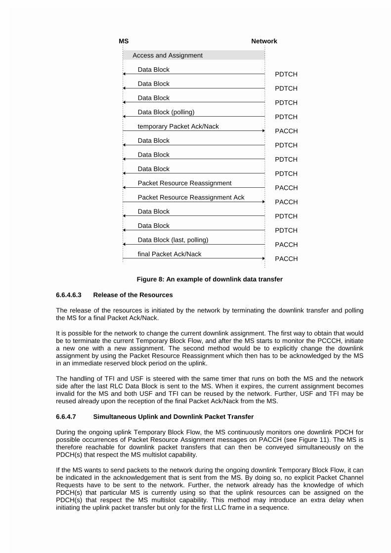
Figure 15 shows an example of message sequence for (multislot) downlink data transfer with oneresource reassignment and possible RLC Data Block re-transmissions.
Data Block
temporary Packet Ack/Nack
Access and Assignment
MS Network
PDTCH
PACCH
Packet Resource Reassignment
Packet Resource Reassignment Ack
PACCH
PACCH
PACCHfinal Packet Ack/Nack
Data BlockPDTCH
Data BlockPDTCH
Data Block (polling)PDTCH
Data BlockPDTCH
Data BlockPDTCH
Data BlockPDTCH
Data BlockPDTCH
Data BlockPDTCH
Data Block (last, polling)PACCH
Figure 8: An example of downlink data transfer
6.6.4.6.3 Release of the Resources
The release of the resources is initiated by the network by terminating the downlink transfer and pollingthe MS for a final Packet Ack/Nack.
It is possible for the network to change the current downlink assignment. The first way to obtain that wouldbe to terminate the current Temporary Block Flow, and after the MS starts to monitor the PCCCH, initiatea new one with a new assignment. The second method would be to explicitly change the downlinkassignment by using the Packet Resource Reassignment which then has to be acknowledged by the MSin an immediate reserved block period on the uplink.
The handling of TFI and USF is steered with the same timer that runs on both the MS and the networkside after the last RLC Data Block is sent to the MS. When it expires, the current assignment becomesinvalid for the MS and both USF and TFI can be reused by the network. Further, USF and TFI may bereused already upon the reception of the final Packet Ack/Nack from the MS.
6.6.4.7 Simultaneous Uplink and Downlink Packet Transfer
During the ongoing uplink Temporary Block Flow, the MS continuously monitors one downlink PDCH forpossible occurrences of Packet Resource Assignment messages on PACCH (see Figure 11). The MS istherefore reachable for downlink packet transfers that can then be conveyed simultaneously on thePDCH(s) that respect the MS multislot capability.
If the MS wants to send packets to the network during the ongoing downlink Temporary Block Flow, it canbe indicated in the acknowledgement that is sent from the MS. By doing so, no explicit Packet ChannelRequests have to be sent to the network. Further, the network already has the knowledge of whichPDCH(s) that particular MS is currently using so that the uplink resources can be assigned on thePDCH(s) that respect the MS multislot capability. This method may introduce an extra delay wheninitiating the uplink packet transfer but only for the first LLC frame in a sequence.

(Tdoc SMG2/3 WPA 97A216)
CHANGE REQUEST No. A023 rev.1
Technical Specification GSM 03.64 version 5.0.0
Status at SMG [ ]: Approved [ ] Rejected [ ] Postponed [ ]
Phase 1: [ ] Phase 2: [ ] Phase 2+: [Release 97] Work item: GPRS
Other phase(s) affected: [ ] If yes, linked CR(s):
Proposed change affects: SIM [ ] ME [X] Network [X]
Source: SMG2 WPA Date: 13 July 1997
Subject: Improved RLC Service Primitives
Category: F - Correction [ ]A - Corresponds to a Phase 2 correction [ ]B - Addition of Feature [ ]C - Functional modification of Feature [x]D - Editorial modification [ ]
Reason for change:
It has been agreed that MM signalling will be carried with the channel coding providing best transmissionquality on the radio interface. However, there is no mechanism to pass this requirement to the lowerlayers. This change request adds such a capability into GSM 03.64.
The maximum length of the LLC frame has been aligned with GSM 03.60.
Sections affected, and additional explanation of details of change (if needed):
Subclauses6.6.3 improvements to the definition of RLC/MAC service primitives and providing RLC/MAC user
selected option for picking up the most appropriate channel coding scheme Separate primitive forPTM has been introduced, to include the transmission repeat count as a parameter.
6.6.4 correction to the definition of maximum LLC frame length6.8 mapping of PTM-M into RLC/MAC-PTM_DATA
Attached revised pages:
Page(s):
If other core Specifications are affected, necessary (and attached) Joint CRs:
Affects(possibly):
MS Test Specifications [ ] BSS Test Specifications [ ] O&M Specifications [ ]
Attached CRs?:
Cross Phase Compatibility:
Change affects operation of: Phase 1 MS in Phase 2(+) NW [ ] Phase 2(+) MS in Phase 1 NW [ ]
Change affects operation of: Phase 1 SIM in Phase 2(+) ME[ ] Phase 2(+) SIM in Phase 1 ME [ ]
Other comments:
None
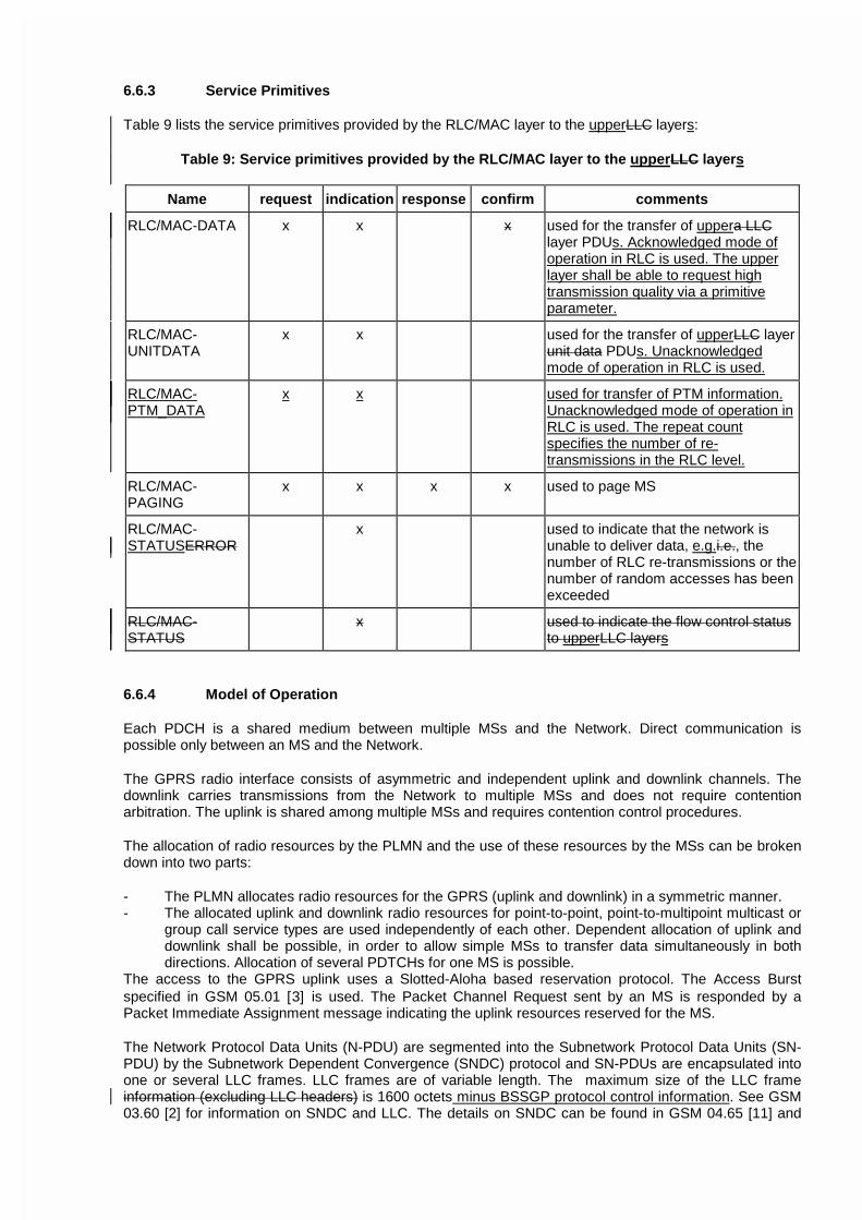
6.6.3 Service Primitives
Table 9 lists the service primitives provided by the RLC/MAC layer to the upperLLC layers:
Table 9: Service primitives provided by the RLC/MAC layer to the upperLLC layers
Name request indication response confirm comments
RLC/MAC-DATA x x x used for the transfer of uppera LLClayer PDUs. Acknowledged mode ofoperation in RLC is used. The upperlayer shall be able to request hightransmission quality via a primitiveparameter.
RLC/MAC-UNITDATA
x x used for the transfer of upperLLC layerunit data PDUs. Unacknowledgedmode of operation in RLC is used.
RLC/MAC-PTM_DATA
x x used for transfer of PTM information.Unacknowledged mode of operation inRLC is used. The repeat countspecifies the number of re-transmissions in the RLC level.
RLC/MAC-PAGING
x x x x used to page MS
RLC/MAC-STATUSERROR
x used to indicate that the network isunable to deliver data, e.g.i.e., thenumber of RLC re-transmissions or thenumber of random accesses has beenexceeded
RLC/MAC-STATUS
x used to indicate the flow control statusto upperLLC layers
6.6.4 Model of Operation
Each PDCH is a shared medium between multiple MSs and the Network. Direct communication ispossible only between an MS and the Network.
The GPRS radio interface consists of asymmetric and independent uplink and downlink channels. Thedownlink carries transmissions from the Network to multiple MSs and does not require contentionarbitration. The uplink is shared among multiple MSs and requires contention control procedures.
The allocation of radio resources by the PLMN and the use of these resources by the MSs can be brokendown into two parts:
- The PLMN allocates radio resources for the GPRS (uplink and downlink) in a symmetric manner.- The allocated uplink and downlink radio resources for point-to-point, point-to-multipoint multicast or
group call service types are used independently of each other. Dependent allocation of uplink anddownlink shall be possible, in order to allow simple MSs to transfer data simultaneously in bothdirections. Allocation of several PDTCHs for one MS is possible.
The access to the GPRS uplink uses a Slotted-Aloha based reservation protocol. The Access Burstspecified in GSM 05.01 [3] is used. The Packet Channel Request sent by an MS is responded by aPacket Immediate Assignment message indicating the uplink resources reserved for the MS.
The Network Protocol Data Units (N-PDU) are segmented into the Subnetwork Protocol Data Units (SN-PDU) by the Subnetwork Dependent Convergence (SNDC) protocol and SN-PDUs are encapsulated intoone or several LLC frames. LLC frames are of variable length. The maximum size of the LLC frameinformation (excluding LLC headers) is 1600 octets minus BSSGP protocol control information. See GSM03.60 [2] for information on SNDC and LLC. The details on SNDC can be found in GSM 04.65 [11] and

the details on LLC can be found in GSM 04.64 [12]. LLC frames are segmented into RLC Data Blocks. Atthe RLC/MAC layer, a selective ARQ protocol (including block numbering) between the MS and theNetwork provides retransmission of erroneous RLC Data Blocks. When a complete LLC frame issuccessfully transferred across the RLC layer, it is forwarded to the LLC layer.
6.8 PTM-M Data Transfer
PTM-M data, in the form of individual LLC frames, is mapped into RLC/MAC-PTM_DATA primitive anddistributed from SGSN to the BSS representing the cells that are defined by a geographical areaparameter. To the cells concerned, the BSS for each PTM-M LLC frame:
− Optionally, sends a “PTM-M new message” indicator on all individual paging channels on PCCCH ifallocated, otherwise on CCCH. The indication refers to a PTM-M notification channel PNCH onPCCCH or NCH on CCCH, where a notification for the new PTM-M message can be received.
If the indicator option is not supported, or if an MS can not receive the indicator when expected, e.g.because the corresponding block in the multiframe structure is used for other purposes than paging,the MS must read the notification channel.
− Sends a PTM-M notification on PNCH or NCH. The notification has the form of a Packet ResourceAssignment for the PTM-M LLC frame. The notification includes a group identity IMGI and an allocationof a TFI to be used in all RLC blocks of the LLC frame.
− Transmits the PTM-M LLC frame on the assigned downlink resources.
Transfer of PTM-M data is carried out without any ARQ on the RLC/MAC and LLC layers. Instead,retransmission of LLC frames is used.
− Retransmits the PTM-M LLC frame the specified number of times. For each retransmission, a separatePTM-M notification (resource assignment) is sent but with the same TFI as in the first transmission.
An MS accumulates correctly received RLC blocks from each transmission to assemble an LLC frame.
The dimensioning of PNCH shall be scaleable depending on capacity requirements.
An NCH may, if capacity allows, be used as a shared notification channel for PTM-M and AdvancedSpeech Call Items (ASCI).
An MS only interested in PTM-M needs to listen only to PNCH/NCH.

ETSI STC SMG2 WPA / SMG3 WPA Tdoc SMG2/3 WPA 97A223Kista, Sweden18 August - 22 August 1997
CHANGE REQUEST No. A026 rev1
Technical Specification GSM 03.64 version 5.0.0
Submitted to SMG for approval without presentation ("non-strategic") [ ]
with presentation ("strategic") [ ]
Status at SMG [ ]: Approved [ ] Rejected [ ] Postponed [ ]
Phase 1: [ ] Phase 2: [ ] Phase 2+: [Release ‘97] Work item: GPRS
Other phase(s) affected: [ ] If yes, linked CR(s):
Proposed change affects: SIM [ ] ME [ X ] Network [ X ]
Source: SMG2 WPA Date: 20-22/08/1997
Subject: Optimisation for network controlled cell re-selection.
Category: F - Correction [ ]
A - Corresponds to a Phase 2 correction [ ]
B - Addition of Feature [X]
C - Functional modification of Feature [ ]
D - Editorial modification [ ]
Reason for change:
This Change Request introduces a coordination procedure between the MS and the BSS in order to optimisethe usage of the radio resources in special situations where the network controlled cell re-selectionprocedures (NC1 or NC2 modes of operation) should not be used, particularly when a class A MS issimultaneously involved in a circuit switched service and in a GPRS packet transfer. Additional explanationsare provided in Tdoc SMG2 WPA 97A132.
Sections affected, and additional explanation of details of change (if needed):
6.5.6.4 Modified as explained above.
Attached revised pages:
Page(s): 27.
If other core Specifications are affected, necessary (and attached) Joint CRs:
Affects(possibly):
MS Test Specifications [ ] BSS Test Specifications [ ] O&M Specifications [ ]
Attached CRs?:
Cross Phase Compatibility:
Change affects operation of: Phase 1 MS in Phase 2(+) NW [ ] Phase 2(+) MS in Phase 1 NW [ ]
Change affects operation of: Phase 1 SIM in Phase 2(+) ME[ ] Phase 2(+) SIM in Phase 1 ME [ ]
Other comments:

GSM 03.64 version 5.0.0 27 TS 03 64 V5.0.0 (1997-07)
Two sets of parameters are broadcast on PBCCH and are valid in Transfer and Wait state respectively for all MSs in thecell. NETWORK_CONTROL_ORDER can also be sent individually to an MS on PACCH, in which case it overridesthe broadcast parameter.
The measurement reports shall be sent individually from each MS as RLC transmissions, addressed to the RRmanagement in BSS. The measurement reporting shall be maintained in the MS RR states Wait with Cell Update andTransfer and in the BSS RR states Measurement Report Reception and Transfer.
The measurement reports shall contain the measurements that the MS normally performs, as indicated by the BA-GPRSlist, and shall include the following information:
- RXLEV serving cell;
- a quality measure for serving cell;
- number of valid neighbours;
- RXLEV up to 6 neighbours;
- broadcast frequency, identifying up to 6 neighbours.
The measurement report may contain RXLEV measurements, without BSIC verification, on additional frequencies,ordered for the benefit of frequency allocation schemes.
In Transfer state, the quality measure shall include the following measurements on the PDCH that contains PACCH:
- the average interference level γch (see 6.5.8.3.2).
In Wait state, the quality measure shall include the following measurements on the PCCCH:
- the average interference level γch (see subclause 6.5.8.3.2);
- a BER measure obtained from the PPCH of that MS.
The cell re-selection command shall include:
- target cell channel description (GSM 04.08);
- penalty to prevent immediate return (3 bits);
- penalty timer (5 bits).
Situations may appear where the network controlled cell re-selection procedures (NC1 or NC2 modes of operation)should not be used:
- When a class A mobile station is simultaneously involved in a circuit switched service and in a GPRS transfer. Inthis case, handover for the circuit switched service has precedence over GPRS network controlled cell re-selection. In order to avoid that measurements are reported twice by the MS (once for the GPRS resource, oncefor the circuit switched resource), thus leading to inefficient usage of the radio bandwidth, network controlledcell re-selection should not be activated in this case.
- When an MS is performing Anonymous Access, cell re-selection implying a change of Routeing Area results inthe MS returning to the GPRS MM IDLE state, see GSM 03.60 [2]. Therefore, there might be cases where thenetwork controlled cell re-selection would result in the Anonymous Access failing.

GSM 03.64 version 5.0.0 27 TS 03 64 V5.0.0 (1997-07)
Since the BSS is not able to detect such situations, the MS shall inform the BSS when such a situation is encountered, sothat the BSS can select a more appropriate mode of operation. This coordination procedure shall be as indicatedhereafter:
- When an MS in Transfer or Wait state has been asked by the network to behave according to the NC1 or NC2modes of operation and the MS encounters one of the above mentioned situations, it shall continue to reportmeasurements and shall not obey to network controlled cell re-selection commands, if received and, in addition:
- As soon as an uplink transmission opportunity occurs, the MS shall inform the network that the requestedmode of operation should be suspended.
- It shall be up to the network to decide whether to maintain or to change the mode of operation. The networkshall reply with the value to be used.
- The MS shall adapt its behaviour accordingly. If no answer is received from the network, the MS shallassume no change and shall continue to inform the network, as described above, until an answer is received.
- When the situation which triggered the above mentioned actions ends, and provided that the MS is still inTransfer or Wait state:
- As soon as an uplink transmission opportunity occurs, the MS shall inform the network that the initial modeof operation (NC1 or NC2) may resume.
- It shall be up to the network to decide whether to maintain or to change the mode of operation. The networkshall reply with the value to be used.
- The MS shall adapt its behaviour accordingly. If no answer is received from the network, the MS shallassume no change (i.e. it shall continue to apply the last value received from the network) and it shallcontinue to inform the network, as described above, until an answer is received.
6.5.7 Timing Advance
The timing advance procedure is necessary because a proper value for timing advance has to be used for the uplinktransmission of Radio blocks.
The timing advance procedure comprises two parts:
- initial timing advance estimation;
- continuous updating.
6.5.7.1 Initial timing advance estimation
The initial timing advance estimation is made from the single access burst carrying the Packet Channel Request. ThePacket Immediate Assignment or Packet Resource Assignment then carries the estimated timing advance value to theMS. That value should be used by the MS for the uplink transmissions until the continuous updating provides a newvalue (see subclause 6.5.7.2).
In the case when Packet Queuing Notification is used the initial estimated timing advance may become too old to be sentin the Packet Immediate Assignment. The Packet Polling Message can then be used to trigger the transmission of anaccess burst from which the timing advance can be estimated. Alternatively Packet Immediate Assignment can be

1
ETSI STC SMG2/3 WPA/GPRS revison of Tdoc SMG2/3 WPA 97A232Kista/Stockholm, Sweden18 - 22 August, 1997
CHANGE REQUEST No. A027r2
Technical Specification GSM 03.64, version 5.0.0
Submitted to SMG for approval without presentation ("non-strategic") [ ]
with presentation ("strategic") [ ]
Status at SMG [ ]: Approved [ ] Rejected [ ] Postponed [ ]
Phase 1: [ ] Phase 2: [ ] Phase 2+: [Release’97] Work item: GPRS
Other phase(s) affected [ ] If yes, linked CR(s):
Proposed change affects: SIM [ ] ME [X] Network [ ]
Source: SMG2 WPA Date: 20 August, 1997
Subject: Abnormal cases in GPRS MS Ready State: Leaky bucket procedure
Category: F - Correction [ ]
A - Corresponds to a phase 2 correction [ ]
B - Addition of Feature [ ]
C - Functional modification of Feature [X]
D - Editorial modification [ ]
Reason for change:
The subclause 6.7.4 packet nack or absence of response is proposed to be a flexible leaky bucket type measurementbased on a packet ack/nack counter as being optional depending on parameter settings. This subclause 6.7.4 is coveringthe situation “Broken RLC Connection” in the RLC/MAC Protocol Operation, see Tdoc SMG2/3 WPA 97A120 § 2.4.
Sections affected, and additional explanation of details of change (if needed):
Attached revised page(s): Relevant page(s) for subclause 6.7 in GSM 03.64 (5.0.0).
If other core Specifications are affected, necessary (and attached) Joint CRs:
Affects (possibly): MS Test Specifications [ ] BSS Test Specifications[ ] O&M Specifications [ ]
Attached CRs?:
Cross Phase Compatibility:
Change affects operation of: Phase 1 MS in Phase 2(+) NW [ ] Phase 2(+) MS in Phase 1 NW [ No]
Change affects operation of: Phase 1 SIM in Phase 2(+) ME[No ] Phase 2(+) SIM in Phase 1 ME [No]
Other comments:

2
6.7 Abnormal cases in GPRS MS Ready State
6.7.4 Packet Nack or Absence of Response
When sending data blocks on PDTCH, a Packet Ack/Nack shall be sentresponded on PACCH. If no responses havebeen received or only Packet Nacks have been received within a predifined time , then the RLC retransmission datablocks and the remaining blocks shall continue after a cell re-selection procedure based onMS shall use a leaky buckettype measurement like the DSC.in order to determine when to perform cell re-selection.
Packet Nack or Absense of Response shall use a Packet Ack/Nack counter (PAN) initialised initiated to Z upon RLCconnection establishment. If Nack or no response or Nack is received within a predefined time, then PAN decrements byX4. If Packet Ack is received, then PAN increments by Y1 but never exceeding Z. The parameters X, Y and Z caneither be fixed orare broadcast on PBCCH or BCCH[FFS]. When PAN ≤ 0 is reached, a cell re-selection procedure istriggered, as for the PPCH or the PRACHPacket Channel rRequest fFailures (subclause 6.7.3 above).
Note: A possible implementation could be as follows. The parameters X, Y and Z as well as the RETRY bit “randomaccess retry to another cell” (subclause 6.7.3 above) shall be broadcast on PBCCH or BCCH in intervals not longer thanevery 8 multiframes (~2 s). The parameter values for X and Y: 0,1,2,3,4,5,6,7; for Z: 4,8,12,16,20,24,28,32; forRETRY: allowed 1, not allowed 0. The leaky bucket procedure will be disabled by setting X=Y=0. Other timers andcounters are defined in the RLC/MAC Protocol Operation.

1
ETSI STC SMG2/3 WPA (revision of Tdoc SMG2/3 WPA 97A215)Kista/Stockholm, Sweden18-22 August, 1997
CHANGE REQUEST No. A030 rev 1
Technical Specification GSM 03.64, version 5.0.0
Submitted to SMG for approval without presentation ("non-strategic") [ ]
with presentation ("strategic") [ ]
Status at SMG [ ]: Approved [ ] Rejected [ ] Postponed [ ]
Phase 1: [ ] Phase 2: [ ] Phase 2+: [Release’97] Work item: GPRS
Other phase(s) affected [ ] If yes, linked CR(s):
Proposed change affects: SIM [ ] ME [X] Network [ ]
Source: SMG2 WPA Date: 27 June, 1997
Subject: Abnormal cases in GPRS MS Ready State
Category: F - Correction [ ]A - Corresponds to a phase 2 correction [ ]B - Addition of Feature [ ]C - Functional modification of Feature [X]D - Editorial modification [ ]
Reason for change:The first subclause 6.7.1 ”RLC/MAC-Error Causes”: reasons are obsolete in a specification, so being deleted. The nextsubclause 6.7.2 the downlink signalling failure is treated like classical GSM in idle mode, see GSM 05.08 subclause 6.5.For PPCH the BS_PPA_MFRMS = 64/SPLIT_PG_CYCLE, (CR GSM 03.64-A017). The next subclause 6.7.3 packetchannel request failure: a cell re-selection is performed as described for the call re-establishment procedure in GSM05.08 subclause 6.7.2 but based on BA(GPRS) sent on the serving cell PBCCH, but not on its PACCH to loosecapacity. This cell re-selection is performed after the maximum number of random access attempt counters (N1 or N2)have expired in the ”RLC/MAC Protocol Operation”, (see Tdoc SMG2 GPRS 240/97 concerning GSM 04.08), and isperformed only if the ”random access retry to another cell” parameter bit (FFS; broadcast on PBCCH or BCCH by thecell on which the failure occurred) indicates that a reattempt shall be attempted. The next subclause 6.7.4 packet nack orabsence of response is pending a modified leaky bucket type measurement based on a packet ack/nack counter as beingoptional. The old subclause 6.7.5 ”PLMN Search” being covered by the PLMN selection process in GSM 03.22 isdeleted pending service dependent PLMN selection is decided in GSM 02.60.
Sections affected, and additional explanation of details of change (if needed):
Attached revised page(s): Relevant page(s) for subclause 6.7 in GSM 03.64 (5.0.0).
If other core Specifications are affected, necessary (and attached) Joint CRs:Affects (possibly): MS Test Specifications [ ] BSS Test Specifications[ ] O&M Specifications [ ]Attached CRs?:
Cross Phase Compatibility:Change affects operation of: Phase 1 MS in Phase 2(+) NW [ ] Phase 2(+) MS in Phase 1 NW [ ]
CR to 09.90 attached: NoChange affects operation of: Phase 1 SIM in Phase 2(+) ME[ ]
CR to 09.91 attached: NoPhase 2(+) SIM in Phase 1 ME [ ]CR to 09.91 attached: No
Other comments:

2
6.7 Abnormal cases in GPRS MS Ready State
6.7.1 RLC/MAC-Error Causes
The RLC/MAC error causes and procedures to handle these can be found abnormal cases of providing RLC/MAC-ERROR indication are equivalent not succeeding LOCATION UPDATING in GSM 03.22, 04.08, and 05.08. Thereasons can be too far distance for Timing Advance (TA > 63) between MS and ordinary BSS, too lowcarrier/(Interference + Noise) (C/(I+N) < 9 dB) on BSS or MS, as well as some malfunction of BSS or MS.
6.7.2 Packet Paging Request Downlink Signalling Failures
The quality of the channels for downlink signalling is determined by the downlink signalling counter DSC. Its operationis described in GSM 05.08. In case a PPCH is allocated, the counter is initialized to max[10,(90/64)*SPLIT_PG_CYCLE].Packet Paging Request failures of PPCH shall be based on the Downlink Signalling Counter reaching to 0 (DSC≤0)resulting in cell re-selection, i.e. putting down the upper BCCH carrier in the MS NCELL list to the lowest on the list for30 s penalty time and resetting the DSC counter, see GSM 05.08.If four successive request cycles for all decoded BCCH carriers in the MS NCELL list have failed, then go to PLMNsearch (see GSM 04.08).
6.7.3 Packet Channel Request Failures
Packet Channel Request fFailures on PRACH is an abnormal case of MS by receiving no Packet Immediate AssignmentAcknowledgement (Ack or Nack) (within a random backoff time 5 s) on PAGCH or AGCH after transmission initiatedon PRACH or RACH. for two successive random access attempts per NCELL shall result in cell re-selection, i.e. puttingdown the upper BCCH carrier in the NCELL list to the lowest on the list for a 30 s penalty time, see also GSM 04.08.If four successive request cycles for all decoded BCCH carriers in the MS NCELL list have failed, then go to PLMNsearch (see GSM 04.08).
Only if ”random access retry to another cell” is allowed (PBCCH or BCCH parameter bit FFS), the MS shall follow thecell re-selection procedure defined for the call re-establishment procedure in GSM 05.08 based on BA(GPRS) after themaximum number of random access attempts has been reached.
Otherwise if ”random access retry to another cell” is not allowed (PBCCH or BCCH parameter bit FFS), the MS shallfollow the normal RLC/MAC procedure.
6.7.4 Packet Nack or Absence of Response
When sending data blocks on PDTCH, a Packet Ack/Nack shall be responded on PACCH. If no responses have beenreceived or only Packet Nacks have been received , then the RLC retransmission data blocks and the remaining blocksshall continue after a cell re-selection procedure based on a leaky bucket type measurement like the DSC.Packet Nack or Absense of Response shall use a Packet Ack/Nack counter (PAN) initiated to Z. If no response or Nackis received, then PAN decrements by 4. If Packet Ack is received, then PAN increments by 1 but never exceeding Z.The parameter Z can either be fixed or broadcast on PBCCH [FFS]. When PAN ≤ 0 is reached, a cell re-selectionprocedure is triggered, as for the PPCH or the PRACH request failures.
6.7.5 PLMN Search
If no suitable cell of the Home PLMN can be used for packet data transfer with cell re-selection procedures, then thestate PLMN SEARCH shall be entered as stated in GSM 04.08. If PLMN NOT ALLOWED is received or registrationfailure is obtained on all PLMNs, the indicate RLC/MAC-ERROR and continue searching for PLMN, see GSM 03.22.