Embed Size (px)
Citation preview
1EINC Data Sheet TA200137 Issue 2/B 25/09/03
Data Sheet
EINCEthernet Internetwork Node Controller
ETHERNET INTERNETWORK NODE
CONTROLLER
Description
The EINC, Ethernet Internetwork Node Controller, provides themeans by which the Building Management System network canincorporate an Ethernet network. The EINC operates at theinternetwork level, including the necessary support for WAN’s (e.g.TMN support). It also provides virtual CNCs which allow supervisoryor tool software running in PCs connected to the Ethernet networkto connect to the BMS system.
It is provided with a 10 BASE-T interface, and an AUI connectorwhich allows an alternative network transceiver to be used.
Features
• Facilitates use of Ethernet network in BMS system• 10 BASE-T interface and AUI connector for alternative transceivers.• Four virtual CNCs for PC connection via Ethernet.• EINCs can span routers• Ethernet provides faster signalling rate.• Integration of BMS network into existing Ethernet system.• Automatic reporting of network population• Network alarms available in 10 languages• EEPROM retains configured data during power fail (no battery
required).
Physical
~
1 2 3 4 5 6 7 8 9 10
TX RX
OK
LAN
OK
TX RX
~230V
RDS/RS232 !MODEM24V
� � �
� � � � � � � � 00.10.70.00.UD.BB
�
S/No:Q3B____X73010003
� � � � � � � Location
� � � � � � � � 00.10.70.00.UD.BB
S/No:Q3B____X73010003EINC -400007096
� � � � � � �
� � � � � � �
mains ac supplyconnector
power/watchdogLEDs
230 mm (9.06")
Ethernet LEDs address/baud switch
current loopnetworkconnector
current loopnetwork LEDs
Ethernet (10BASE-T) connector Ethernet transceiver (AUI) connector
70 mm (2.76")
181
mm
(7.
13")
earth busbar
24 Vac supplyconnector
2 EINC Data Sheet TA200137 Issue 2/B 25/09/03
EINC Data Sheet
FUNCTIONALITY
SYSTEM
The EINC acts as an interface between the BMS current loop network and the Ethernet network. This enables it to be used in a numberof applications (a more detailed description of its uses is given in the Ethernet Products Engineering Guide, TE200369):
Virtual CNCs
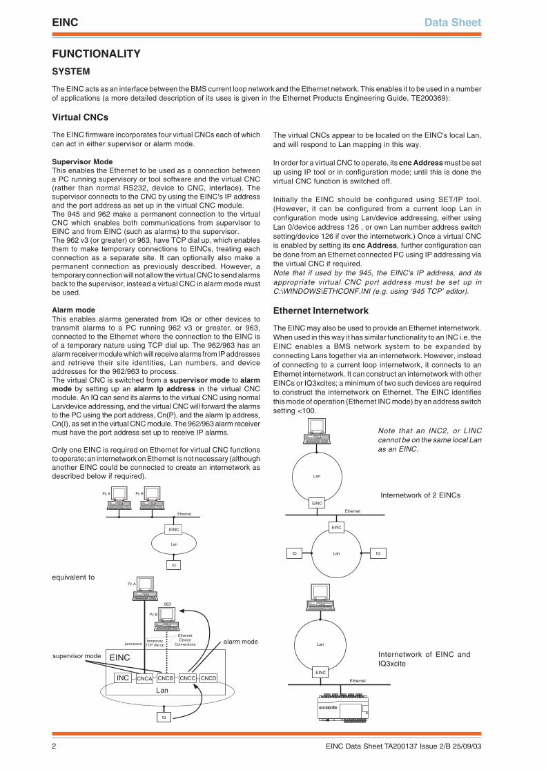
The EINC firmware incorporates four virtual CNCs each of whichcan act in either supervisor or alarm mode.
Supervisor ModeThis enables the Ethernet to be used as a connection betweena PC running supervisory or tool software and the virtual CNC(rather than normal RS232, device to CNC, interface). Thesupervisor connects to the CNC by using the EINC's IP addressand the port address as set up in the virtual CNC module.The 945 and 962 make a permanent connection to the virtualCNC which enables both communications from supervisor toEINC and from EINC (such as alarms) to the supervisor.The 962 v3 (or greater) or 963, have TCP dial up, which enablesthem to make temporary connections to EINCs, treating eachconnection as a separate site. It can optionally also make apermanent connection as previously described. However, atemporary connection will not allow the virtual CNC to send alarmsback to the supervisor, instead a virtual CNC in alarm mode mustbe used.
Alarm modeThis enables alarms generated from IQs or other devices totransmit alarms to a PC running 962 v3 or greater, or 963,connected to the Ethernet where the connection to the EINC isof a temporary nature using TCP dial up. The 962/963 has analarm receiver module which will receive alarms from IP addressesand retrieve their site identities, Lan numbers, and deviceaddresses for the 962/963 to process.The virtual CNC is switched from a supervisor mode to alarmmode by setting up an alarm Ip address in the virtual CNCmodule. An IQ can send its alarms to the virtual CNC using normalLan/device addressing, and the virtual CNC will forward the alarmsto the PC using the port address, Cn(P), and the alarm Ip address,Cn(I), as set in the virtual CNC module. The 962/963 alarm receivermust have the port address set up to receive IP alarms.
Only one EINC is required on Ethernet for virtual CNC functionsto operate; an internetwork on Ethernet is not necessary (althoughanother EINC could be connected to create an internetwork asdescribed below if required).
The virtual CNCs appear to be located on the EINC's local Lan,and will respond to Lan mapping in this way.
In order for a virtual CNC to operate, its cnc Address must be setup using IP tool or in configuration mode; until this is done thevirtual CNC function is switched off.
Initially the EINC should be configured using SET/IP tool.(However, it can be configured from a current loop Lan inconfiguration mode using Lan/device addressing, either usingLan 0/device address 126 , or own Lan number address switchsetting/device 126 if over the internetwork.) Once a virtual CNCis enabled by setting its cnc Address, further configuration canbe done from an Ethernet connected PC using IP addressing viathe virtual CNC if required.Note that if used by the 945, the EINC's IP address, and itsappropriate virtual CNC port address must be set up inC:\WINDOWS\ETHCONF.INI (e.g. using ‘945 TCP’ editor).
Ethernet Internetwork
The EINC may also be used to provide an Ethernet internetwork.When used in this way it has similar functionality to an INC i.e. theEINC enables a BMS network system to be expanded byconnecting Lans together via an internetwork. However, insteadof connecting to a current loop internetwork, it connects to anEthernet internetwork. It can construct an internetwork with otherEINCs or IQ3xcites; a minimum of two such devices are requiredto construct the internetwork on Ethernet. The EINC identifiesthis mode of operation (Ethernet INC mode) by an address switchsetting <100.
� � � �
� � � � �� �
� � �
� � � � � � � �
� � � �
Note that an INC2, or LINCcannot be on the same local Lanas an EINC.
Lan
IQ
Ethernet
Pc A Pc B
EINC
IQ
Pc A
Pc B
EthernetDevice
Connectionstemporary
TCP dial uppermanent
963
CNCAINC
EINC
CNCB
Lan
CNCC CNCD
equivalent to
supervisor mode
alarm mode
EINC
Lan
Ethernet
4 5 6
27 8 9
310 11 12
413 14 15
516 17 18
619 20 21
722 23 24
825 26 27
928 29 30
10+ 0+ 0 + 0 + 0 + 0 + 0+ 0+ 0+ 0
1 2 3
1+ 0
0 V24 V
24 V 34 35 36
12
37 38 39
13
40 41 42
14A
31 32 33P
11
43 44 45
15
46 47 48
16100-240 V
OK RXP 0 P 0 P 0P 0 P 0 P 0
Internetwork of 2 EINCs
Internetwork of EINC andIQ3xcite
3EINC Data Sheet TA200137 Issue 2/B 25/09/03
Data Sheet EINC
SYSTEM (continued)
Internetwork Ethernet extension
The EINC may also be used to extend a current loop internetworkinto an Ethernet internetwork. In this mode it acts as a routerbetween the current loop internetwork and the Ethernet network(e.g. EINC A in diagram below). A minimum of two EINCs or anEINC and an IQ3xcite are required to construct such aninternetwork. The EINC takes a Lan address on the internetworkwhich is used to identify the EINC for configuration purposes andas a Lan for its virtual CNCs (see below). The EINC identifies thismode of operation (internetwork extension mode) by an addressswitch =>100.
Stand Alone Mode
An EINC can be set to ‘Stand Alone’ by the IP tool. It will notattempt to build networks with other EINCs or IQ3xcites, but willstill communicate as a single EINC as above (with supervisors viavirtual CNCs and with its local Lan). An EINC should be set tostand alone mode to reduce Ethernet network traffic (i.e. to disablepolling messages trying to ‘find’ other Novar Trend Ethernetdevices).
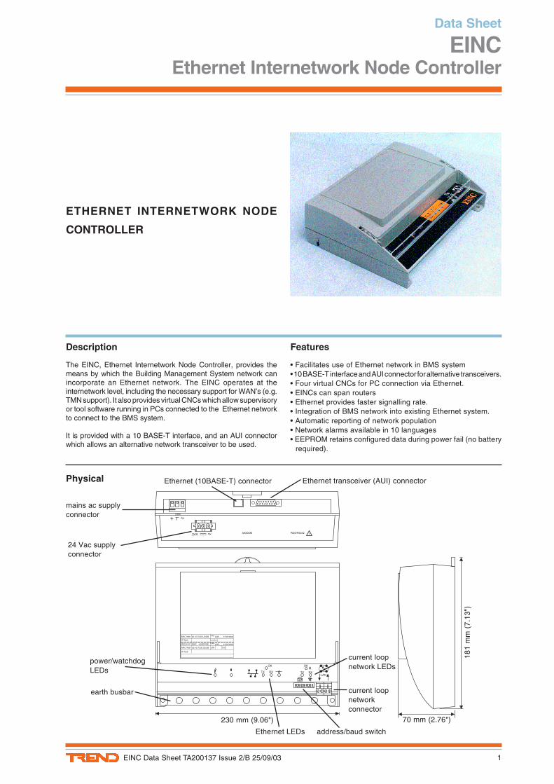
EINC with IQ3xcite
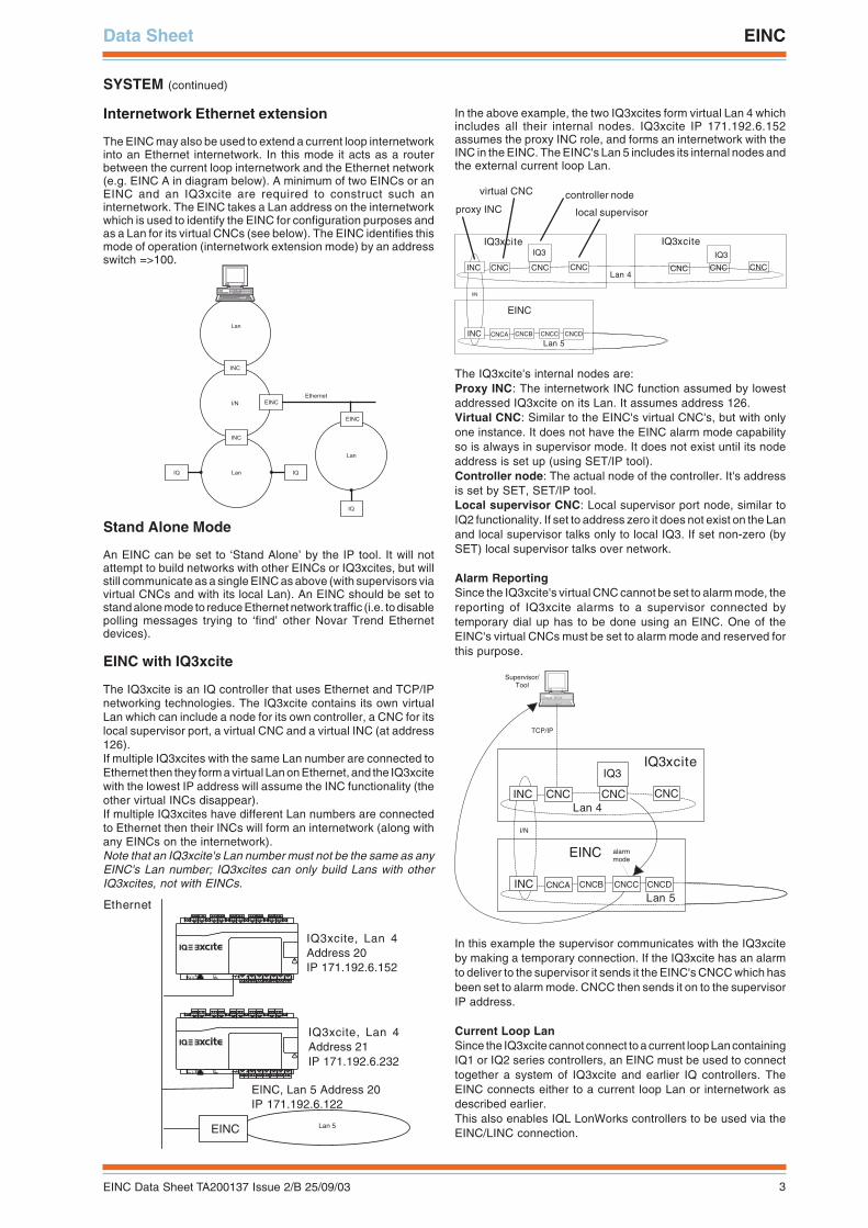
The IQ3xcite is an IQ controller that uses Ethernet and TCP/IPnetworking technologies. The IQ3xcite contains its own virtualLan which can include a node for its own controller, a CNC for itslocal supervisor port, a virtual CNC and a virtual INC (at address126).If multiple IQ3xcites with the same Lan number are connected toEthernet then they form a virtual Lan on Ethernet, and the IQ3xcitewith the lowest IP address will assume the INC functionality (theother virtual INCs disappear).If multiple IQ3xcites have different Lan numbers are connectedto Ethernet then their INCs will form an internetwork (along withany EINCs on the internetwork).Note that an IQ3xcite's Lan number must not be the same as anyEINC's Lan number; IQ3xcites can only build Lans with otherIQ3xcites, not with EINCs.
In the above example, the two IQ3xcites form virtual Lan 4 whichincludes all their internal nodes. IQ3xcite IP 171.192.6.152assumes the proxy INC role, and forms an internetwork with theINC in the EINC. The EINC's Lan 5 includes its internal nodes andthe external current loop Lan.
The IQ3xcite's internal nodes are:Proxy INC: The internetwork INC function assumed by lowestaddressed IQ3xcite on its Lan. It assumes address 126.Virtual CNC: Similar to the EINC's virtual CNC's, but with onlyone instance. It does not have the EINC alarm mode capabilityso is always in supervisor mode. It does not exist until its nodeaddress is set up (using SET/IP tool).Controller node: The actual node of the controller. It's addressis set by SET, SET/IP tool.Local supervisor CNC: Local supervisor port node, similar toIQ2 functionality. If set to address zero it does not exist on the Lanand local supervisor talks only to local IQ3. If set non-zero (bySET) local supervisor talks over network.
Alarm ReportingSince the IQ3xcite's virtual CNC cannot be set to alarm mode, thereporting of IQ3xcite alarms to a supervisor connected bytemporary dial up has to be done using an EINC. One of theEINC's virtual CNCs must be set to alarm mode and reserved forthis purpose.
In this example the supervisor communicates with the IQ3xciteby making a temporary connection. If the IQ3xcite has an alarmto deliver to the supervisor it sends it the EINC's CNCC which hasbeen set to alarm mode. CNCC then sends it on to the supervisorIP address.
Current Loop LanSince the IQ3xcite cannot connect to a current loop Lan containingIQ1 or IQ2 series controllers, an EINC must be used to connecttogether a system of IQ3xcite and earlier IQ controllers. TheEINC connects either to a current loop Lan or internetwork asdescribed earlier.This also enables IQL LonWorks controllers to be used via theEINC/LINC connection.
� � � � �� �
� � �
� � �
� � �
� � �
� � � �
� �
� � � � � � � �
� � � �
� �
Ethernet
Lan 5EINC
4 5 6
27 8 9
310 11 12
413 14 15
516 17 18
619 20 21
722 23 24
825 26 27
928 29 30
10+ 0+ 0 + 0 + 0 + 0 + 0+ 0+ 0+ 0
1 2 3
1+ 0
0 V24 V
24 V 34 35 36
12
37 38 39
13
40 41 42
14A
31 32 33P
11
43 44 45
15
46 47 48
16100-240 V
OK RXP 0 P 0 P 0P 0 P 0 P 0
4 5 6
27 8 9
310 11 12
413 14 15
516 17 18
619 20 21
722 23 24
825 26 27
928 29 30
10+ 0+ 0 + 0 + 0 + 0 + 0+ 0+ 0+ 0
1 2 3
1+ 0
0 V24 V
24 V 34 35 36
12
37 38 39
13
40 41 42
14A
31 32 33P
11
43 44 45
15
46 47 48
16100-240 V
OK RXP 0 P 0 P 0P 0 P 0 P 0
IQ3xcite, Lan 4Address 20IP 171.192.6.152
IQ3xcite, Lan 4Address 21IP 171.192.6.232
EINC, Lan 5 Address 20IP 171.192.6.122
CNC
IQ3
INC
IQ3xcite
CNC CNCLan 4
I/N
CNCAINC
EINC
CNCB
Lan 5CNCC CNCD
TCP/IP
Supervisor/ Tool
alarm mode
CNC
IQ3
IQ3xcite
CNC CNCCNC
IQ3
INC
IQ3xcite
CNC CNCLan 4
I/N
CNCAINC
EINC
CNCB
Lan 5CNCC CNCD
proxy INC
virtual CNC controller node
local supervisor
4 EINC Data Sheet TA200137 Issue 2/B 25/09/03
EINC Data Sheet
SYSTEM (continued)
IQ3xcite and TMNThe IQ3xcite does not have an integral autodialling facility, butautodialling can be achieved by using a TMN connected to anEINC's current loop network.The EINC should operate in internetwork extension mode (i.e.device address =>100) which provides a current loop internetworkwith an extension on Ethernet. However, this will only give normaltext communications, it cannot provide IQ3xcite's web pages.
The diagram below shows the equivalent diagram showing currentloop networks and virtual networks.
The internetwork now connects together the IQ3xcite, EINC andTMN. The autodialled supervisor or tool PC, E, is connected tothe TMN by a current loop Lan.
AddressingAs explained above an EINC can be configured from a currentloop Lan using its configuration mode. However, IQ3xcite doesnot have traditional configuration mode; it is intended to beconfigured using SET, with the facility to make parameter changesvia Ethernet using a browser and the IQ3xcite's own server(webpages).IQ3xcite has to have its IP address, subnet mask, UDP port, setup using SET/IP tool prior to it being accessible via its IP address.IP tool is recommended to be used to set up both IQ3xcites andEINCs. The device is initially identified by its unique MAC address(printed on the front panel label).This requires the PC running SET and the IP tool to be connectedto Ethernet. The IP tool can automatically fetch the details of allthe Novar Trend IP devices (EINCs and IQ3xcites) on its ownsegment of Ethernet; it can also fetch details from devices theother side of a router by reading the 'remote Trend devices'information (see below) from an IQ3xcite or EINC if the userenters the remote device’s IP address (alternatively the user canenter the details by hand).The IP tool also enables the current loop Lan and outstationaddress, the default router, the Virtual CNCs, and the remoteTrend devices (see below) to be configured, and for the deviceto be set stand alone if required.The IP, Lan, and outstation addresses should be written on thelabel; a tear off adhesive label strip with the unit's IP, Lan, andoutstation addresses can be used for a paper record e.g. logbook.
Routers
On EINCs pre version 4.1, although EINCs enabled Ethernet tobe used as an internetwork, the internetwork could not span arouter. On version 4.1 or greater EINCs can construct aninternetwork across a router.However, using all versions of EINC, it is possible for PCs toconnect to EINCs via routers, and to treat EINCs separated byrouters as separate sites.IQ3xcites also have the ability to span routers and EINCs orIQ3xcites are interchangeable in the description below, with thefollowing exceptions in IQ3xcite: no configuration mode, nobroadcast/directed option, no updatelist feature.
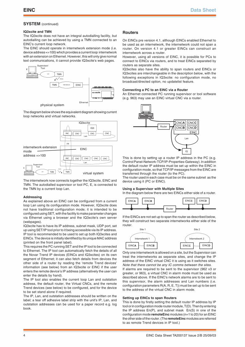
Connecting a PC to an EINC via a RouterAn Ethernet connected PC running supervisor or tool software(e.g. 963) may use an EINC virtual CNC via a router.
This is done by setting up a router IP address in the PC (e.g.Control Panel-Network-TCP/IP-Properties-Gateway). In additionthe default router IP address must be set up within the EINC inconfiguration mode, so that TCP/IP messages from the EINC aretransferred through the router (to the PC).The router used in each case must be on the same subnet as thedevice using it (PC or EINC).
Using a Supervisor with Multiple SitesIn the diagram below there are two EINCs either side of a router.
If the EINCs are not set up to span the router as described below,they will construct two separate internetworks either side of therouter.
Only one internetwork is allowed on a site, but the Supervisor cantreat the internetworks as separate sites, and change the IPaddress of the EINC virtual CNC it is using as it switches sites.Note that there cannot be any IC comms between the sites.If alarms are required to be sent to the supervisor (962 v3 orgreater, or 963), a virtual CNC in alarm mode must be used asdescribed above. If the EINC's network alarms are to be sent tothis supervisor, the alarm addresses and Lan numbers (i.e.configuration parameters R(A, R, E, T)) must be set up to be sentto the address of the virtual CNC in alarm mode.
Setting up EINCs to span RoutersThis is done by firstly setting the default router IP address by IPtool or in configuration mode router module, T(D). Then by enteringthe IP address En(P), and subnet mask En(S) in one of theconfiguration mode remoteEinc modules (n=1 to 20) for an EINCthe other side of the router. (The remoteEinc modules are referredto as remote Trend devices in IP tool.)
� � �
� �
� � � � � �� � � �
� � � �
� � � �
� � � �� � � �
� � � � � �
� � � � � � � � � � � � � � �� � � � �
� � � � � � � � � �� � � � �� � � � �
� � � � � � � � � � � � � � � � � � � � � � � � � � � �
� � � � � � � � � � � � � �
Supervisor/ Tool
Ethernet
Internetwork EINCTMN
Lan
PSTN
TMN
E
4 5 6
27 8 9
310 11 12
413 14 15
516 17 18
619 20 21
722 23 24
825 26 27
928 29 30
10+ 0+ 0 + 0 + 0 + 0 + 0+ 0+ 0+ 0
1 2 3
1+ 0
0 V24 V
24 V 34 35 36
12
37 38 39
13
40 41 42
14A
31 32 33P
11
43 44 45
15
46 47 48
16100-240 V
OK RXP 0 P 0 P 0P 0 P 0 P 0
CNC
IQ3
INC
IQ3xcite
CNC CNC
Lan
I/N
CNCINC
EINC
CNC
Lan
CNC CNC
Supervisor/ Tool
TMNLan TMN
PSTNE
internetwork extensionmodeaddress =>100
virtual system
physical system

5EINC Data Sheet TA200137 Issue 2/B 25/09/03
Data Sheet EINC
SYSTEM (continued)
In the above diagram, EINCA is configured with the default routerIP address and the remote EINC's (EINCB's) IP address andsubnet mask. It will send a message to EINCB. EINCB will thenreply and the EINCA will construct the internetwork between thetwo EINCs.In EINC v4.2 or greater (and IQ3xcites) EINCB will rememberEINCA's IP address and subnet mask and be able to constructthe internetwork across the router from its side (as long as it hasits own default router set up).(In earlier versions of EINC, EINCB would also have to be set upwith EINCA’s IP address and subnet mask.)
Multiple routers: The default router can be any router on thesame subnet as the device using it. It will pass the message toa router on the remote EINC’s subnet.
Multiple EINCs: As explained above in ‘Using a Supervisor withMultiple Sites’, if EINC's are not set up to span routers, they willconstruct separate internetworks on subnets separated by routers.
If the EINC one side of the router is set up with the details of anEINC the other side, they will construct an internetwork acrossthe router.The EINC with the lowest IP address (master) is responsible forcreating the internetwork across the router.In the diagram above, EINCA has the lowest IP address andshould be set up with the information for an EINC the other side,e.g. EINCC. The two internetworks will combine.
If EINCC were to be switched off, the message initiated by EINCAwould still reach the remaining EINC on the far subnet (EINCD)if it were to be sent as a broadcast message. Broadcast messagesare sent to all devices on the subnet (i.e. EINCC and EINCD). AllEINCs on the same channel (i.e. between routers) must be on thesame subnet. By default the EINC will operate in broadcast mode,but most users disable their routers from sending broadcastmessages for security reasons, and only directed messages arepermitted.
Without broadcasting, if EINCC were to be switched off, theinternetwork across the router will be broken from both directions.To prevent this happening EINCA should have details of bothEINC and EINCD. In the above system it would be recommendedthat both EINCA and EINCB have details of EINCC and EINCDand vice versa, this gives a reasonable level of redundancy incase of failure.In a more general system each EINC on one side of a routershould have details of as many EINCs as possible on each subnetthe other side of the router. With reasonable risk two devicesfrom each subnet could be used.It is recommended that the two lowest IP addresses one sideof a router have details of the two lowest IP addresses oneach subnet of the system the other side of the router.
Broadcast/Directed: There is an option, E(B), in the remoteEincslist page to switch remote broadcasts on or off ('send remoteBroadcasts'); this is not available in IQ3xcites. Normally if theoption is set on (broadcast), messages will be sent through therouter as 'directed' to the remote EINC's IP address and also tothe router requesting a 'broadcast' message to be sent to theremote EINC's subnet. If the option is set off, then the messagefrom EINCA to EINCC will only be directed, and if EINCC wereto be switched off then the internetwork across the router will belost, and communication with EINCD would be broken.As explained above most users disable routers from sendingbroadcast messages for security reasons in which case 'sendremote broadcasts' should be switched off and directedmessaging only used.
Update List: The setting up of several EINCs across routers isfacilitated by the uPdatelist configuration module (EINC only,not IQ3xcite). This enables one EINC's remoteEincs list to beset up, and then for it to be copied across to all the other EINCson the system including those on the local subnet, and thoseacross routers. It uses the remoteEincs list to discover the remotesubnets, so details of at least one EINC from every subnet mustbe set up on the list. When update list is initiated the list is sentto each known EINC, and then each one of them will pass it onto every other EINC on its subnet. A remote EINC will then havethe same list set up and will use it to create the internetwork fromits perspective, so the list must also contain the details of theoriginal EINC.
If using the uPdatelist facility described above, EINCA shouldhave its own details plus those of EINCB, C, and D set up in itslist so that it can be copied across to the other EINCs.
As a general rule, before using uPdatelist, if 'send remoteBroadcasts' is 'yes' details of only one EINC from each subnetand of this EINC should be set up in the remoteEINCs list (remoteTrend devices); if 'send remote Broadcasts ' is 'no' (orbroadcasting is disabled for security reasons) details of as manyEINCs as possible from each subnet and from this EINC's subnetshould be set up in the remoteEINCs list (remote Trend devices).Note that uPdatelist facility also transmits the broadcast/directedflag status to the other EINCs.
Internet Access: Because the Internet uses TCP/IP addressing,the 962v3 or 963 communication with the EINC can operate overthe Internet. Company Internet access is normally protected bya firewall which is usually the responsibility of the company's ITdepartment. The firewall will need to be set up to allow messagesthrough the port addresses being used for sending and receivingBMS system messages. Additionally the firewall may be set upeither to pass messages through or to redirect them. If redirectionis being used, then the messages are sent to the firewall IPaddress and the firewall must be set up with the BMS system IPaddress so it can pass them on. If using an impermanent ISPconnection (e.g. via a dial up modem) at either 962/963 or EINCend, the ISP must support reverse dial up.Note that EINC to EINC networking communications will notoperate across a firewall (i.e. virtual networks cannot be builtacross firewalls).
IQ3xcite and EINC with routersAs explained above IQ3xcites also have the capability to spanrouters and EINCs or IQ3xcites are almost completelyinterchangeable. However, since IQ3xcites do not haveconfiguration mode, they have to be set up using SET/IP tool.Also IQ3xcites do not have the updatelist feature, but IP tool hasfunctionality to facilitate the setting up of remote Trend devicesby copying the settings from one device to another. On a combinedIQ3xcite/EINC site the remote Trend devices should be set upusing IP tool rather than using the updatelist feature.
� � � � � � � � � �
� � � � � �
Remote EINC
� � � � � �� � � � � � � � � �
� � � � � �
Default Router
EINCA EINCDEINCCEINCB
Router
171.192.6.152 171.192.6.232 171.192.0.106 171.192.0.143
T(D) = Default Router IP addressEn(P) = Remote EINC IP addressEN(S) = Remote EINC Subnet mask
Default Router
6 EINC Data Sheet TA200137 Issue 2/B 25/09/03
EINC Data Sheet
SYSTEM (continued)
Because the IQ3xcites communicate across the router only usingdirected messages, details of as many EINCs/IQ3xcites aspossible from each subnet across routers should be set up asremote Trend devices.
Again the general rule applies: It is recommended that the twolowest IP addresses one side of a router have details of thetwo lowest IP addresses on each subnet of the system theother side of the router.
UDP Port:
The UDP (User Datagram Protocol) port number defines theEthernet port used by the EINCs to send messages to each other.To construct an internetwork, the EINCs must be on the samesubnet (unless set up to span routers), and must use the sameUDP port. If the user is restricted to using one subnet, but wishesto have separate sites on that subnet (i.e. more than oneinternetwork), then he can set different UDP port numbers for thegroups of EINCs in the different internetworks.
The above diagram is equivalent to two independentinternetworks, but without using a router.
Serial Port Servers
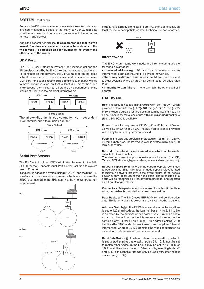
The EINC with its virtual CNCs eliminates the need for the 849/SPS (Ethernet Connect/Serial Port Server) solution to systemuse of Ethernet.If an EINC is added to a system using 849/SPS, and the 849/SPSinterface is to be maintained, care must be taken to ensure theEINC is connected to the SPS 'spur' via the 4 to 20 mA currentloop network.
e.g.
either
or
If the SPS is already connected to an INC, then use of EINC onthat Ethernet is incompatible; contact Technical Support for advice.
� � �
� � �
� � � � � � � �
� �
� � � �
� � �
� � �
� � � � �
� � � � � � � �
� � � �
� �
� � �
� � � � � � � �
� � � �
� �
� � � � � � � � � �� � � � �� � � � �
� � � � � � � � � � � � �
� � � � � � � � � �� � � � �� � � � �
� � � � � � � � � � � � �
� � � � � � � � � � � � � �
� � � � � � �� � � � � � �
� � � � � � � � � � � � � �
Same Subnet
Same Subnet
Internetwork
The EINC is an internetwork node; the internetwork gives thefollowing advantages:• Increased addressing - 116 Lans may be connected via aninternetwork each Lan having 116 devices networked.• There may be different baud rates in each Lan - this is relevantto older systems where an area may be limited to low baud rates(1k2).• Immunity to Lan failure - if one Lan fails the others will stilloperate.
HARDWARE
Box: The EINC is housed in an IP30 network box (NBOX), whichprovides a plastic 230 mm (9.06")x 181 mm (7.13") x 70 mm (2.76")IP30 enclosure suitable for three point mounting via 8 mm (0.31")holes. An optional metal enclosure with cable glanding knockouts(ENCLS/MBOX) is available.
Power: The EINC requires in 230 Vac, 50 or 60 Hz at 18 VA, or24 Vac, 50 or 60 Hz at 24 VA. The 230 Vac version is providedwith an optional supply terminal shroud.
Fusing: The 230 Vac version is protected by 125 mA (T), 250 V,20 mm supply fuse, the 24 Vac version is protected by 1.6 A, 20mm supply fuse.
Network: The network connection is a 4 wide set of 2 part terminals,suitable for 2 wire cables.The standard current loop node features are included (Lan OK,TX, and RX indicators, bypass relays, network alarm generation).
Network bypass relay: In order the current loop Lan continuesto operate if the EINC fails, a set of node bypass relays is fittedto maintain network integrity in the event failure of the node’spower supply, or failure of the node itself. The bypassing of anode will be recognised by the downstream node, and reportedas a Lan Changed alarm.
Connectors: Two part connectors are used throughout to facilitatewiring. A busbar is provided for screen termination.
Data Backup: The EINC uses EEPROM to hold configurationdata. This is non-volatile to power failure without need for a battery.
Address Switch : The EINC device address on the local Lanis set to 126 (hard coded); the Lan number (1, 4 to 9, 11 to 99)is selected by the address switch poles 1 to 7. It must be set toa Lan number unique on the internetwork and cannot be thesame as any IQ3xcite Lan number. An address setting <100identifies the EINC mode of operation as current loop Lan/Ethernetinternetwork whereas =>100 identifies the mode of operation ascurrent loop internetwork/Ethernet internetwork.
Baud Rate Switch : The baud rate on the current loop networkis set by address/baud rate switch poles 8 to 10. It must be setto match other nodes on the Lan. It may be set to 1k2, 9k6, or19k2 baud. It may also be set to 38k4 baud by selecting both 1k2and 19k2, although this rate can only be used with other node 2devices (e.g. INC2).
7EINC Data Sheet TA200137 Issue 2/B 25/09/03
Data Sheet EINC
HARDWARE (continued)
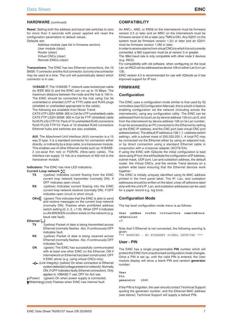
Reset: Setting both the address and baud rate switches to zerofor more than 3 seconds with power applied will reset theconfiguration parameters to default values.Defaults are:
Address module (see list in firmware section)User module (clear)Router (clear)Virtual CNCs (clear)Remote EINCs (clear)
Transceivers: The EINC has two Ethernet connections, the 10BASE-T connector and the AUI connector, but only one connectormay be used at a time. The unit will automatically detect whichconnector is in use.
10 BASE-T: The 10 BASE-T network uses twisted pair cable(to IEEE 802.3) and the EINC can run up to 10 Mbps. Themaximum distance between the node and the hub is 100 m.The EINC should be connected to the hub using Cat 5eunshielded or shielded (UTP or FTP) cable and RJ45 plugs(shielded or unshielded appropriate to the cable).The following are available from Novar Trend:CAT5 UTP LSZH 305M: 305 m Cat 5e UTP (unshielded) cableCAT5 FTP LSZH 305M: 305 m Cat 5e FTP (shielded) cableRJ45 PLUG UTP/10: Pack of 10 unshielded RJ45 connectorsRJ45 PLUG FTP/10: Pack of 10 shielded RJ45 connectorsEthernet hubs and switches are also available.
AUI: The Attachment Unit Interface (AUI) connector is a 15way D type. It is a standard connector for connection eitherdirectly, or indirectly by a drop cable, to a transceiver module.This enables use of other Ethernet media such as 10 BASE-2 (co-axial thin net) or FOR/RL (fibre-optic cable). Theinterface can supply 12 Vdc at a maximum of 400 mA to thetransceiver module.
Indicators: The EINC has nine LED indicators.Current Loop network
TX :(yellow) Indicates current flowing from the EINCcurrent loop network transmitter (normally ON). IfOFF indicates open circuit.
RX :(yellow) Indicates current flowing into the EINCcurrent loop network receiver (normally ON). If OFFindicates open circuit or short circuit.
OK :(green) This indicates that the EINC is able to sendand receive messages on the current loop network(normally ON). Flashes when prohibited addressswitch setting (0, 2, 3, >119). When OFF it indicatesa LAN BROKEN condition exists on the network (e.g.baud rate fault).
Ethernet TX :(yellow) Packet of data is being transmitted across
Ethernet (normally flashes ~6s). If continuously OFFindicates fault.
RX :(yellow) Packet of data is being received acrossEthernet (normally flashes ~6s). If continuously OFFindicates fault.
OK :(green) The EINC has successfully communicatedwith at least one other EINC on the Ethernet. ON ifinternetwork on Ethernet has been constructed. OFFif EINC alone (e.g. using virtual CNCs only)
(Link Integrity): (yellow) On when connection to Ethernetsystem detected (voltage present on network). NormallyON; if OFF indicates faulty Ethernet connection). Onlyapplies to 10BASE-T use; OFF for AUI use.
(Power) :(green) On when power supply is connected.(Watchdog):(red) Flashes when EINC has internal fault.
COMPATIBILITY
An ANC+, AND, or XN28 on the internetwork must be firmwareversion 2.5 or later and an MNC on the internetwork must befirmware version 2.54 or later (any TMN is OK). Any IQ251 on thesystem must be firmware version 1.2U or later and an IQ241must be firmware version 1.2M or later.In order to receive alarms from virtual CNCs to which it is not currentlyconnected, a 962 supervisor must be at version 3 or greater.The 38k4 baud rate is only compatible with other node 2 devices(e.g. INC2).For compatibility with old software, when configuring on the localLan, an INC2 can be addressed as device 126 on either Lan 0 or Lan126.EINC version 4.2 is recommended for use with IQ3xcite as it hasimproved support for IP tool.
FIRMWARE
Configuration
The EINC uses a configuration mode similar to that used by IQcontrollers (see IQ Configuration Manual); this is a built-in featureenabling configuration via the network (including across theinternetwork), using any configuration utility. The EINC can beaddressed from its local Lan by device address 126 on Lan 0, andfrom the internetwork by device address 126 on its Lan number.It can be accessed by an PC connected to the Ethernet by settingup the EINC IP address, and the CNC port (see virtual CNC portaddress below). The default IP address is 128.1.1.<address switchsetting>, with a subnet mask of 255.255.255.1. A local PC maybe connected via the Ethernet either by using an adjacent hub,or by direct connection using a standard Ethernet cable inconjunction with a crossover adapter (XCITE/XA).If using the EINC with IQ3xcite the initial configuration is bestdone using IP tool; this will facilitate the configuration of IP address,subnet mask, UDP port, Lan and outstation address, the defaultrouter, the Virtual CNCs, and the remote Trend devices on asystem wide basis ensuring that the Ethernet devices worktogether.The EINC is initially uniquely identified using its MAC addressprinted in the front panel label. The IP, Lan, and outstationaddresses should be written on the label; a tear off adhesive labelstrip with the unit's IP, Lan, and outstation addresses can be usedfor a paper record e.g. log book.
Configuration Mode
The top level configuration mode menu is as follows:
User addRes rouTer virtualCncs remoteEincsuPdatelist=?
Note that if Ethernet is not connected, the following warning isgiven:*** WARNING - NO ETHERNET SIGNAL DETECTED ***
User - PIN
The EINC has a single programmable PIN number which willprotect the EINC from unauthorised configuration mode changes.Once a PIN is set up, until the valid PIN is entered, the Usermodule display will show a blank PIN and random generatornumber.
UserPingenerator 1060
If the PIN is forgotten, the user should contact Technical Supportquoting the generator number, and the Ethernet MAC address(see below); Technical Support will supply a default PIN.
8 EINC Data Sheet TA200137 Issue 2/B 25/09/03
EINC Data Sheet
FIRMWARE (continued)
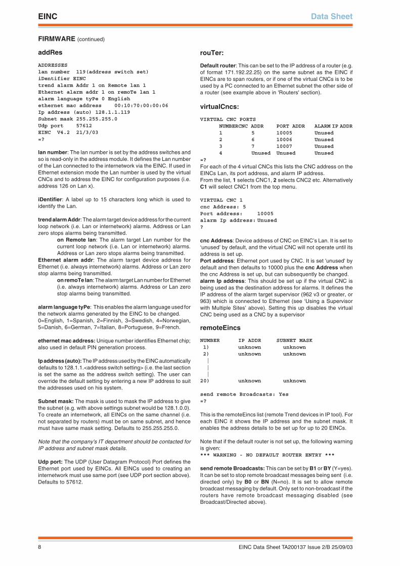
addRes
ADDRESSESlan number 119(address switch set)iDentifier EINCtrend alarm Addr 1 on Remote lan 1Ethernet alarm addr 1 on remoTe lan 1alarm language tyPe 0 Englishethernet mac address 00:10:70:00:00:06Ip address (auto) 128.1.1.119Subnet mask 255.255.255.0Udp port 57612EINC V4.2 21/3/03=?
lan number: The lan number is set by the address switches andso is read-only in the address module. It defines the Lan numberof the Lan connected to the internetwork via the EINC. If used inEthernet extension mode the Lan number is used by the virtualCNCs and to address the EINC for configuration purposes (i.e.address 126 on Lan x).
iDentifier: A label up to 15 characters long which is used toidentify the Lan.
trend alarm Addr: The alarm target device address for the currentloop network (i.e. Lan or internetwork) alarms. Address or Lanzero stops alarms being transmitted.
on Remote lan: The alarm target Lan number for thecurrent loop network (i.e. Lan or internetwork) alarms.Address or Lan zero stops alarms being transmitted.
Ethernet alarm addr: The alarm target device address forEthernet (i.e. always internetwork) alarms. Address or Lan zerostop alarms being transmitted.
on remoTe lan: The alarm target Lan number for Ethernet(i.e. always internetwork) alarms. Address or Lan zerostop alarms being transmitted.
alarm language tyPe: This enables the alarm language used forthe network alarms generated by the EINC to be changed.0=English, 1=Spanish, 2=Finnish, 3=Swedish, 4=Norwegian,5=Danish, 6=German, 7=Italian, 8=Portuguese, 9=French.
ethernet mac address: Unique number identifies Ethernet chip;also used in default PIN generation process.
Ip address (auto): The IP address used by the EINC automaticallydefaults to 128.1.1.<address switch setting> (i.e. the last sectionis set the same as the address switch setting). The user canoverride the default setting by entering a new IP address to suitthe addresses used on his system.
Subnet mask: The mask is used to mask the IP address to givethe subnet (e.g. with above settings subnet would be 128.1.0.0).To create an internetwork, all EINCs on the same channel (i.e.not separated by routers) must be on same subnet, and hencemust have same mask setting. Defaults to 255.255.255.0.
Note that the company's IT department should be contacted forIP address and subnet mask details.
Udp port: The UDP (User Datagram Protocol) Port defines theEthernet port used by EINCs. All EINCs used to creating aninternetwork must use same port (see UDP port section above).Defaults to 57612.
rouTer:
Default router: This can be set to the IP address of a router (e.g.of format 171.192.22.25) on the same subnet as the EINC ifEINCs are to span routers, or if one of the virtual CNCs is to beused by a PC connected to an Ethernet subnet the other side ofa router (see example above in 'Routers' section).
virtualCncs:
VIRTUAL CNC PORTSNUMBERCNC ADDR PORT ADDR ALARM IP ADDR1 5 10005 Unused2 6 10006 Unused3 7 10007 Unused4 Unused Unused Unused
=?
For each of the 4 virtual CNCs this lists the CNC address on theEINCs Lan, its port address, and alarm IP address.From the list, 1 selects CNC1, 2 selects CNC2 etc. AlternativelyC1 will select CNC1 from the top menu.
VIRTUAL CNC 1cnc Address: 5Port address: 10005alarm Ip address: Unused?
cnc Address: Device address of CNC on EINC’s Lan. It is set to‘unused’ by default, and the virtual CNC will not operate until itsaddress is set up.Port address: Ethernet port used by CNC. It is set 'unused' bydefault and then defaults to 10000 plus the cnc Address whenthe cnc Address is set up, but can subsequently be changed.alarm Ip address: This should be set up if the virtual CNC isbeing used as the destination address for alarms. It defines theIP address of the alarm target supervisor (962 v3 or greater, or963) which is connected to Ethernet (see ‘Using a Supervisorwith Multiple Sites’ above). Setting this up disables the virtualCNC being used as a CNC by a supervisor
remoteEincs
NUMBER IP ADDR SUBNET MASK1) unknown unknown2) unknown unknown|||
20) unknown unknown
send remote Broadcasts: Yes=?
This is the remoteEincs list (remote Trend devices in IP tool). Foreach EINC it shows the IP address and the subnet mask. Itenables the address details to be set up for up to 20 EINCs.
Note that if the default router is not set up, the following warningis given:*** WARNING - NO DEFAULT ROUTER ENTRY ***
send remote Broadcasts: This can be set by B1 or BY (Y=yes).It can be set to stop remote broadcast messages being sent (i.e.directed only) by B0 or BN (N=no). It is set to allow remotebroadcast messaging by default. Only set to non-broadcast if therouters have remote broadcast messaging disabled (seeBroadcast/Directed above).
9EINC Data Sheet TA200137 Issue 2/B 25/09/03
Data Sheet EINC
FIRMWARE (continued)
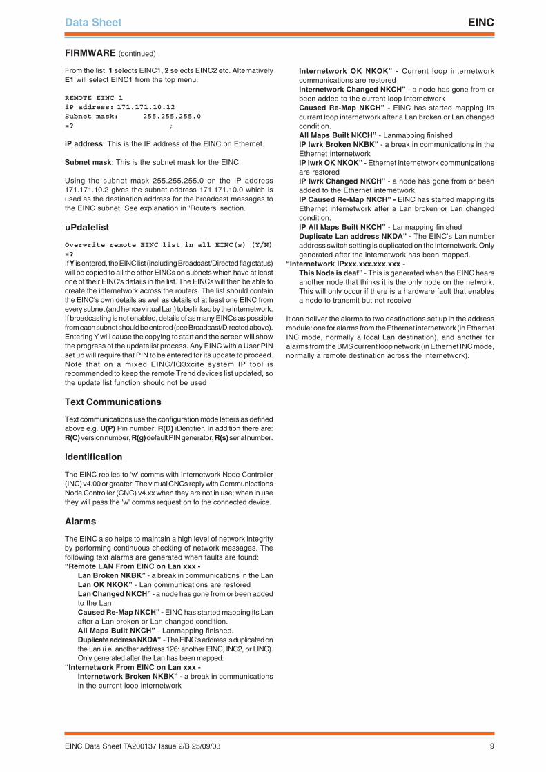
From the list, 1 selects EINC1, 2 selects EINC2 etc. AlternativelyE1 will select EINC1 from the top menu.
REMOTE EINC 1iP address: 171.171.10.12Subnet mask: 255.255.255.0=? ;
iP address: This is the IP address of the EINC on Ethernet.
Subnet mask: This is the subnet mask for the EINC.
Using the subnet mask 255.255.255.0 on the IP address171.171.10.2 gives the subnet address 171.171.10.0 which isused as the destination address for the broadcast messages tothe EINC subnet. See explanation in 'Routers' section.
uPdatelist
Overwrite remote EINC list in all EINC(s) (Y/N)=?If Y is entered, the EINC list (including Broadcast/Directed flag status)will be copied to all the other EINCs on subnets which have at leastone of their EINC's details in the list. The EINCs will then be able tocreate the internetwork across the routers. The list should containthe EINC's own details as well as details of at least one EINC fromevery subnet (and hence virtual Lan) to be linked by the internetwork.If broadcasting is not enabled, details of as many EINCs as possiblefrom each subnet should be entered (see Broadcast/Directed above).Entering Y will cause the copying to start and the screen will showthe progress of the updatelist process. Any EINC with a User PINset up will require that PIN to be entered for its update to proceed.Note that on a mixed EINC/IQ3xcite system IP tool isrecommended to keep the remote Trend devices list updated, sothe update list function should not be used
Text Communications
Text communications use the configuration mode letters as definedabove e.g. U(P) Pin number, R(D) iDentifier. In addition there are:R(C) version number, R(g) default PIN generator, R(s) serial number.
Identification
The EINC replies to 'w' comms with Internetwork Node Controller(INC) v4.00 or greater. The virtual CNCs reply with CommunicationsNode Controller (CNC) v4.xx when they are not in use; when in usethey will pass the 'w' comms request on to the connected device.
Alarms
The EINC also helps to maintain a high level of network integrityby performing continuous checking of network messages. Thefollowing text alarms are generated when faults are found:“Remote LAN From EINC on Lan xxx -
Lan Broken NKBK” - a break in communications in the LanLan OK NKOK” - Lan communications are restoredLan Changed NKCH” - a node has gone from or been addedto the LanCaused Re-Map NKCH” - EINC has started mapping its Lanafter a Lan broken or Lan changed condition.All Maps Built NKCH” - Lanmapping finished.Duplicate address NKDA” - The EINC’s address is duplicated onthe Lan (i.e. another address 126: another EINC, INC2, or LINC).Only generated after the Lan has been mapped.
“Internetwork From EINC on Lan xxx -Internetwork Broken NKBK” - a break in communicationsin the current loop internetwork
Internetwork OK NKOK” - Current loop internetworkcommunications are restoredInternetwork Changed NKCH” - a node has gone from orbeen added to the current loop internetworkCaused Re-Map NKCH” - EINC has started mapping itscurrent loop internetwork after a Lan broken or Lan changedcondition.All Maps Built NKCH” - Lanmapping finishedIP Iwrk Broken NKBK” - a break in communications in theEthernet internetworkIP Iwrk OK NKOK” - Ethernet internetwork communicationsare restoredIP Iwrk Changed NKCH” - a node has gone from or beenadded to the Ethernet internetworkIP Caused Re-Map NKCH” - EINC has started mapping itsEthernet internetwork after a Lan broken or Lan changedcondition.IP All Maps Built NKCH” - Lanmapping finishedDuplicate Lan address NKDA” - The EINC’s Lan numberaddress switch setting is duplicated on the internetwork. Onlygenerated after the internetwork has been mapped.
“Internetwork IPxxx.xxx.xxx.xxx -This Node is deaf” - This is generated when the EINC hearsanother node that thinks it is the only node on the network.This will only occur if there is a hardware fault that enablesa node to transmit but not receive
It can deliver the alarms to two destinations set up in the addressmodule: one for alarms from the Ethernet internetwork (in EthernetINC mode, normally a local Lan destination), and another foralarms from the BMS current loop network (in Ethernet INC mode,normally a remote destination across the internetwork).
10 EINC Data Sheet TA200137 Issue 2/B 25/09/03
EINC Data Sheet
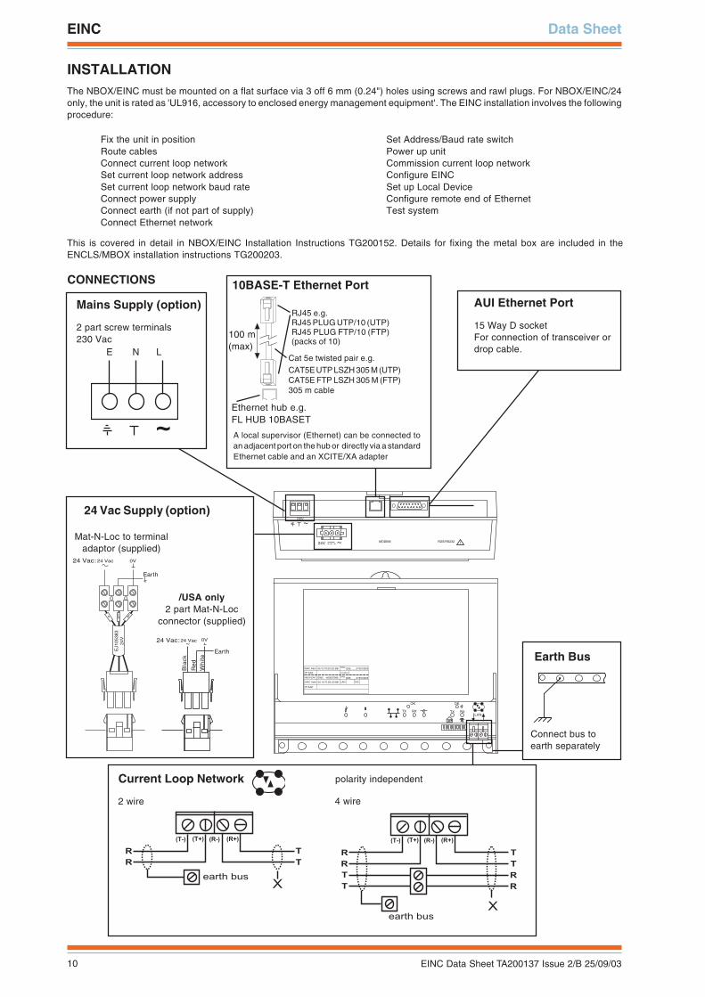
INSTALLATIONThe NBOX/EINC must be mounted on a flat surface via 3 off 6 mm (0.24") holes using screws and rawl plugs. For NBOX/EINC/24only, the unit is rated as 'UL916, accessory to enclosed energy management equipment'. The EINC installation involves the followingprocedure:
Fix the unit in positionRoute cablesConnect current loop networkSet current loop network addressSet current loop network baud rateConnect power supplyConnect earth (if not part of supply)Connect Ethernet network
Set Address/Baud rate switchPower up unitCommission current loop networkConfigure EINCSet up Local DeviceConfigure remote end of EthernetTest system
This is covered in detail in NBOX/EINC Installation Instructions TG200152. Details for fixing the metal box are included in theENCLS/MBOX installation instructions TG200203.
CONNECTIONS
EJ1
0538
324
V
24 Vac:24 Vac
Earth
0V
1 2 3 4 5 6 7 8 9 10
TX RX
OK
LAN
OK
TX RX
~230V
RDS/RS232 !MODEM
~
24V
� � �
� � � � � � � � 00.10.70.00.UD.BB
�
S/No:Q3B____X73010003
� � � � � � � Location
� � � � � � � � 00.10.70.00.UD.BB
S/No:Q3B____X73010003EINC -400007096
� � � � � � �
� � � � � � �
��
� � �
� � � � � � � � �
� � � � � � � � �
� �
�
� � � � � � � � � � � �
�
� � � � � � � �
�
�
�
�
�
�
�
Mains Supply (option)
2 part screw terminals230 Vac
E N L
10BASE-T Ethernet Port
Current Loop Network
2 wire 4 wire
AUI Ethernet Port
15 Way D socketFor connection of transceiver ordrop cable.
24 Vac:24 Vac
Earth
Bla
ck
Red
Wh
ite
0V~
24 Vac Supply (option)
/USA only2 part Mat-N-Loc
connector (supplied)
Earth Bus
Connect bus toearth separately
polarity independent
Cat 5e twisted pair e.g.CAT5E UTP LSZH 305 M (UTP)CAT5E FTP LSZH 305 M (FTP)305 m cable
RJ45 e.g.RJ45 PLUG UTP/10 (UTP)RJ45 PLUG FTP/10 (FTP)(packs of 10)
100 m(max)
Ethernet hub e.g.FL HUB 10BASET
A local supervisor (Ethernet) can be connected toan adjacent port on the hub or directly via a standardEthernet cable and an XCITE/XA adapter
Mat-N-Loc to terminaladaptor (supplied)
11EINC Data Sheet TA200137 Issue 2/B 25/09/03
Data Sheet EINC
MAINTENANCEReplacement of the fuse is described in the NBOX/EINC Installation Instructions TG200152 sheet 1.
DISPOSALCOSHH ASSESSMENT FOR DISPOSAL OF NODE CONTROLLER. No parts affected.
RECYCLING. All plastic and metal parts are recyclable. The printed circuit board may be sent to any PCB recovery contractor to recover some ofthe components for any metals such as gold and silver.
ORDER CODENBOX/EINC/230 :EINC for 230 VAC supply in NBOX plastic enclosure, including busbar and screwsNBOX/EINC/24 :EINC for 24 Vac supply in NBOX plastic enclosure, including busbar and screws
ENCLS/MBOX :Metal box with hinged front panel for NBOX device including busbar, screws, and cable glanding knockoutsFL HUB 10BASET :4 port Ethernet hub.FL SWITCH 5TX :5 port Ethernet switchFL HUB AGENT :4 port Ethernet managed hubCAT5 UTP LSZH 305M :305 m of Cat 5e UTP (unshielded) cable for wiring Ethernet connections.CAT5 FTP LSZH 305M :305 m of Cat 5e FTP (shielded) cable for wiring Ethernet connections.RJ45 PLUG UTP/10 :Pack of 10 unshielded RJ45 connectors for wiring Ethernet connections.RJ45 PLUG FTP/10 :Pack of 10 shielded RJ45 connectors for wiring Ethernet connections.XCITE/XA/5 :Pack of 5 Ethernet connector adapters for direct connection of PC to EINC using standard Ethernet cable.
12 EINC Data Sheet TA200137 Issue 2/B 25/09/03
EINC Data Sheet
Trend Control Systems Ltd reserves the right to revise this publication from time to time and make changes to the content hereofwithout obligation to notify any person of such revisions or changes.
Trend Control Systems Ltd P.O. Box 34 Horsham Sussex RH12 2YF England Tel:+44 (0)1403 211888 Fax:+44 (0)1403 241608 www.trend-controls.com
SPECIFICATION
Electrical
Supply/230 :230 Vac -15%, +10%, 50 or 60 Hz, 18 VA./24 :24 Vac, ±10%, 50 or 60 Hz, 24 VA
Fusing/230 :125 mA (T), 250 V, 20 mm mains fuse/24 :1.6 A (T), 20 mm mains fuse
Data Backup :No battery needed, configuration data storedin non-volatile memory
Current Loop Network:20 mA two wire current loop, opto-isolated polarityindependent, receiver, balanced transmitter
Current loop network distance:Between units dependent on cable type (seetable).
Mechanical
Dimensions :230 mm (9.06") x 181 mm (7.13") x 70 mm(2.76")
MaterialBox :ABSTerminal Cover:Clear Styrolux
Protection :IP30Weight :1.4 kg (3.08 lbs)
Environmental
EMCemissions :EN50081-1immunity :EN50082
Electrical safety :IEC 730-1UL :(NBOX/EINC/24 only) The unit is rated as
'UL916, accessory to enclosed energymanagement equipment.'
Ambient limitsstorage :-10 °C (14 °F) to 50 °C (122 °F)operating :0 °C (32 °F) to 45 °C (113 °F)humidity :0 to 95 %RH non-condensing
Indicators
Current Loop
TX :(yellow) ON if current is flowing from the currentloop network transmitter
RX :(yellow) ON if current is entering the current loopnetwork receiver
OK :(green) ON if EINC successfully communicatingover current loop network.
Ethernet
OK :(green) ON if EINC successfully communicatingover Ethernet with another EINC.
TX :(yellow) EINC transmitting Ethernet datapackets.
RX :(yellow) EINC receiving Ethernet data packets. (Link Integrity):(yellow) On when Ethernet 10 BASE-T
connected properly. (Power) :(green) On when supply is on. (Watchdog) :(red) Flashes when internal fault detected.
Version This document applies to the following versionfirmware :v4.2board :AP103428 issue 1/D
Current loop baud rate :Selectable by board switches 1k2, 9k6,19k2, 38k4 baud - set to be same as othernodes on Lan.
Lan number :Selectable by board switches - Lan numberset to be unique on internetwork; 116 nodesaddressable (1 to 119, excluded addresses2,3, and 10).
Device address :The address of the EINC on the Lan is presetat 126. The four virtual CNC addresses set inconfiguration mode, to be unique on Lan;116 nodes addressable (1 to 119, excludedaddresses 2,3, and 10) per Lan.
Ethernet10 BASE-T :IEEE 802.3AUI :Attachment Unit Interface for attachment to
alternative Ethernet media (e.g. 10 BASE-2).Connectors
10 BASE-T :RJ45 connector, unshielded twisted pair(UTP) cable, 10 Mbps, 100 m.
AUI :15 way D type connector for attachment ofAUI transceiver to convert to other Ethernetmedia (e.g. fibre optic, co-axial). Either directconnection or via drop cable. The interfacesupplies 12 Vdc at 400 mA maximum totransceiver.
Lan/internetwork:2 part connector screw terminals 0.5 to2.5 mm2 cross section area (14 to 20 AWG)cables.
Power :2 part connector screw terminals 0.5 to2.5 mm2 cross section area (14 to 20 AWG)cables.
elbaC duab2k1 duab8k4 duab6k92k91duab
4k83duab
fo.oNseriW
2819nedleBm0001
)sdy0901(m0001
)sdy0901(m0001
)sdy0901(m007
)sdy567(m005
)sdy545(2
7029nedleBm0001
)sdy0901(m0001
)sdy0901(m0001
)sdy0901(m005
)sdy545(m053
)sdy083(2
dnerT005/FH/22/1/1/PT
)1678nedleB(
m0001)sdy0901(
m0001)sdy0901(
m007)sdy567(
m053)sdy083(
m052)sdy072(
2
dnerT005/FH/22/2/2/PT
)3278nedleB(
m0001)sdy0901(
m0001)sdy0901(
m005)sdy545(
m052)sdy072(
m521)sdy531(
4