Embed Size (px)
Citation preview

Disclaimer: SCNZ and the author(s) of this document make no warrantee, guarantee or representation in connection with this
document and shall not be held liable or responsible for any loss or damage resulting from the use of this document Preliminary Bridge Estimating Notes for Design of Steel Composite Bridges Seminar Feb 2011 © Steel Construction New Zealand Inc. 2011 1
ESTIMATING
Preliminary Bridge Estimating Tool – I Girder Bridges Author: Kevin Cowie, Alistair Fussell Affiliation: Steel Construction New Zealand Inc. Date: 7th February 2011 Ref.: Seminar Notes for Design of Steel Composite Bridges Seminar February 2011
Key Words
Bridge Estimating, Estimating, Bridges
Introduction
The likely cost of steelwork is an important consideration in feasibility studies for a bridge project as well as in planning and budgeting for the construction. Very little guidance is published on the cost of bridge steelwork because it is difficult to generalise for the wide range of bridge types and configurations. The price a client
pays for the steelwork in a new bridge covers the cost of many activities and services as well as the basic cost of materials used and the direct workmanship in fabrication and erection. This article presents a simple method for bridge designers to quickly develop preliminary estimates for bridge superstructure steelwork costs. The bridge estimating method is limited to traditional multigirder (I sections, see figures 1 and 2) and ladder deck bridges (see figure 3). The bridge estimating method is suitable for spreadsheet application and example templates have been included. Rates appropriate at the time of the writing this article are given. These are based on feedback from steel bridge constructors. Elemental rates are given for various steelwork activities. Some rates are bundled to enable ease of preparing preliminary estimates. For the most up-to-date rates refer to the Steel Construction New Zealand website: www.scnz.org. When preparing final estimates, it is recommended that rates be confirmed with a suitable steel constructor.
Figure 1: Typical Short Span Multi Girder Bridge Details
Preliminary Bridge Estimating Notes for Design of Steel Composite Bridges Seminar Feb 2011 © Steel Construction New Zealand Inc. 2011 2
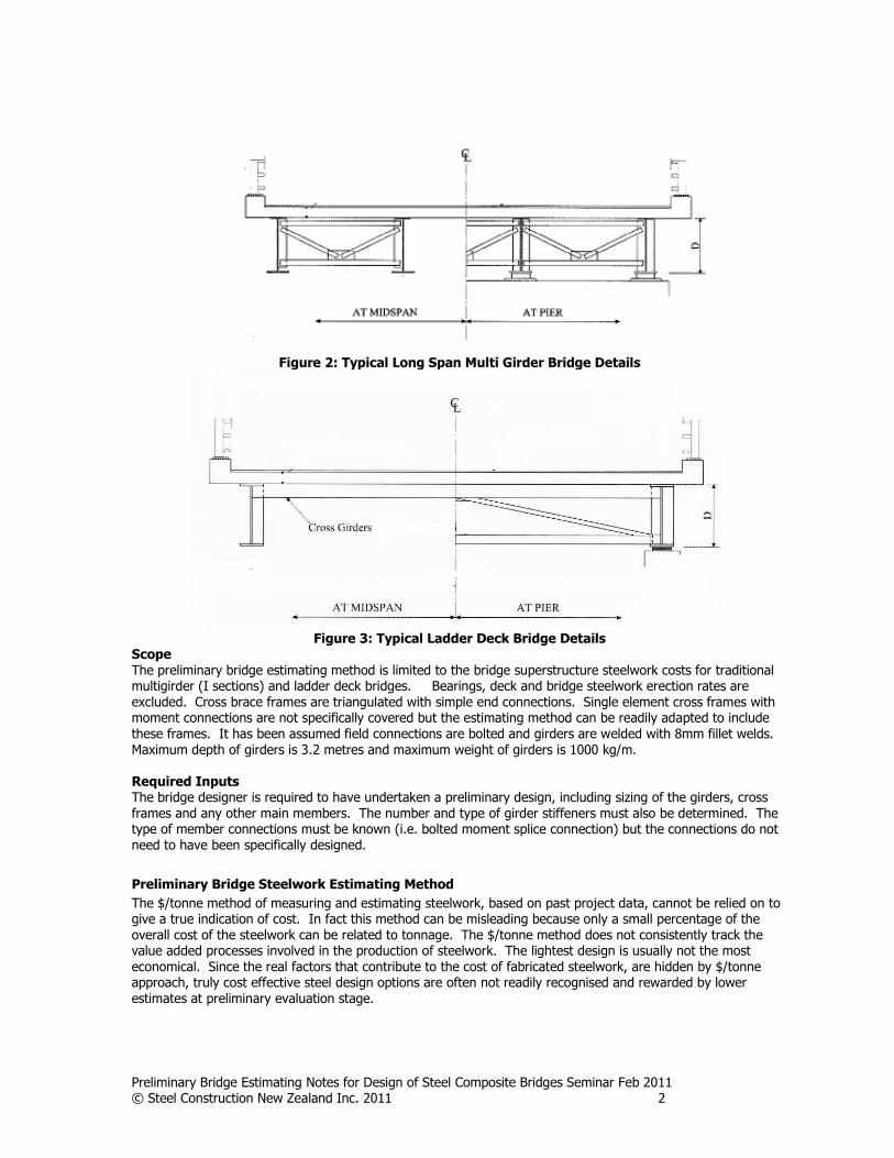
Figure 2: Typical Long Span Multi Girder Bridge Details
Figure 3: Typical Ladder Deck Bridge Details
Scope The preliminary bridge estimating method is limited to the bridge superstructure steelwork costs for traditional multigirder (I sections) and ladder deck bridges. Bearings, deck and bridge steelwork erection rates are excluded. Cross brace frames are triangulated with simple end connections. Single element cross frames with moment connections are not specifically covered but the estimating method can be readily adapted to include these frames. It has been assumed field connections are bolted and girders are welded with 8mm fillet welds. Maximum depth of girders is 3.2 metres and maximum weight of girders is 1000 kg/m. Required Inputs The bridge designer is required to have undertaken a preliminary design, including sizing of the girders, cross frames and any other main members. The number and type of girder stiffeners must also be determined. The type of member connections must be known (i.e. bolted moment splice connection) but the connections do not need to have been specifically designed.
Preliminary Bridge Steelwork Estimating Method
The $/tonne method of measuring and estimating steelwork, based on past project data, cannot be relied on to give a true indication of cost. In fact this method can be misleading because only a small percentage of the overall cost of the steelwork can be related to tonnage. The $/tonne method does not consistently track the value added processes involved in the production of steelwork. The lightest design is usually not the most economical. Since the real factors that contribute to the cost of fabricated steelwork, are hidden by $/tonne approach, truly cost effective steel design options are often not readily recognised and rewarded by lower estimates at preliminary evaluation stage.

Preliminary Bridge Estimating Notes for Design of Steel Composite Bridges Seminar Feb 2011 © Steel Construction New Zealand Inc. 2011 3
A good measurement system identifies the product’s key cost drivers and tracks them with suitable price indicators. Bridge steelwork costs can be readily associated with the following work categories:
Material supply and storage
Fabrication of girders and connections Surface Coatings Transportation Erection
In this article suitable price indicators are selected for the first four of these work categories. These are used to develop the preliminary bridge steelwork estimate. No indicators are given for erection as there are too many factors to consider for bridge construction. The relative costs of bridge steelwork cost (i.e. erection excluded) can be seen in figure 4 which is an example of a multi girder bridge. Each of the work categories and appropriate cost indicators are discussed below. Current rates have been included in the appendix.
Figure 4: Example of a Multi Girder Bridge Steelwork Cost (erection excluded)
Material Supply
Material supply is a major component of bridge steelwork fabrication. For most bridges, costs can be minimised by ordering plates and sections directly from the steel mill. Time has to be allowed in any bridge procurement programme for supply from the mills. Typical lead times are 6 to 8 weeks for plate from New Zealand Steel and 14 to 18 weeks for plate/sections from overseas mills. Australian steel mills hold a limited amount of ex-stock plate/sections. The typical lead times for this are 4 - 6 weeks. Full design information is not necessary to enable orders for steel to be placed but sufficient detail must be available to define all components in advance of rolling dates to minimise waste and costs. New Zealand Steel can supply plate up to 14 m long by 1.5 m wide. The maximum thickness for G300 plate is 50mm. For G350 plate the maximum thickness is 32mm. G300 and G350 plate can be supplied as L0 and L15 plate. The minimum mill order item quantity for AS/NZS 3678 plate is 6 tonnes. Offshore mills can supply plate up to 18 m long by 3.2 m wide. The maximum thickness for G250/G300 plate is
typically 100mm although larger thicknesses are available. The maximum thicknesses for G350 plate in typically 80mm. Weathering steel is also available from offshore mills. The minimum mill order item quantity for plate from offshore mills is typically 10 tonnes, however for weathering steel the minimum mill order item quantity may be greater. Plate availability and lead times may change and for the most up to date information please contact a SCNZ member listed on the web site: www.scnz.org For members fabricated from plate, most plate components including flanges, webs and stiffeners, are cut from plates of appropriate size and width to minimise wastage. Hence steel listing for ordering includes a computerised nesting process to achieve best utilisation and minimise waste to no more than a few percent.

Preliminary Bridge Estimating Notes for Design of Steel Composite Bridges Seminar Feb 2011 © Steel Construction New Zealand Inc. 2011 4
Therefore to reduce wastage, the designer should avoid mixing of grades where possible and rationalise the range of plate thicknesses and section sizes. The designer should consider the standard available plate sizes available. Reducing dimensions may save weight but this could increase the scrap produced, as a result the
anticipated cost savings may not be realised. It is worth spending time determining the optimum section size while keeping an eye on the plate waste remembering to allow for 10mm for the cut. Haunched or tapered webs will increase the wastage unless the plate could also be used for connection cleats and this incorporated into the computer nesting process. The designer should involve the steel bridge fabricator in the final selection of plate sizes and grades. Hot rolled sections indented from overseas mills are available as G300/G350 steel. The minimum mill order item quantity is 10 tonnes. For ex-stock long products typically only a limited amount of G300 sections are held at lengths of 6 / 9 / 12 / 15 / 18m. The supply rate for steel sections and plate is typically quoted in $/metre or $/tonne terms. These are reasonable units of measurement reflecting the cost of energy and high capital input per tonne of the commodity smeltered, rolled and shipped. It also allows steel supply quantities to be easily measured and costed. Typical plate supply rates in New Zealand, at time of publication, for indent orders are given in table 1. Hot
rolled sections supply rates are given in table 2 and are also provided on the SCNZ website: www.scnz.org These rates include an allowance for transport to the fabrication shop, and merchant and fabricator margins. Waste allowance is not included and should be added.
Fabrication of Girders and Connections
Fabrication is generally more economic if connections are simple, geometry is straight forward, and the amount of welding is minimised. Steel bridges tend to incorporate a limited number of generic connection types such as bolted moment splices, stiffeners, and simple brace connections. The detailed design of the connections is often not undertaken until late in the structural design process. However the structural engineer will usually know what type of connection should be used and the relative level of load that it will be required to transmit. Therefore, to assist the estimator and the structural engineer at the preliminary design evaluation stage, tables of typical connections have been listed for the range of common loading conditions. The fabricated price consists of two main components: workstation processing costs and work piece handling costs. The processing operations include saw and gas flame cutting, drilling, hole punching, cropping by guillotine, weld preparation and welding. The handling component is made up of through shop and workstation handling. The connection prices include allowances for supply of bolts and plate fittings. All rates are inclusive of fabricator margin. An estimate is prepared by summing the total number of connections in a project and multiplying by the relevant price / connection, then adding to the allowances for supply of main sections, surface coatings, and transport. Connections can be classified into end connections, work along a member and compound members. For compound members such as girders from three plate members the cost of fabrication is related to their length
and therefore the fabricating of these members is given as a rate per metre. Table 3 provides cost of fabrication of three plate girders. The cost includes stripping of plate, handling, assembly and continuous 8mm fillet weld of web to flanges and non destructive weld testing. Table 4 provides rates for complete penetration butt weld splicing of flange and web plates. Splicing is required where the bridge girder member is greater than the available plate length (typically 18m overseas indent or 12m NZ Steel Ltd) and at location where plate thicknesses change. The rates are for shop welding.
Preliminary Bridge Estimating Notes for Design of Steel Composite Bridges Seminar Feb 2011 © Steel Construction New Zealand Inc. 2011 5
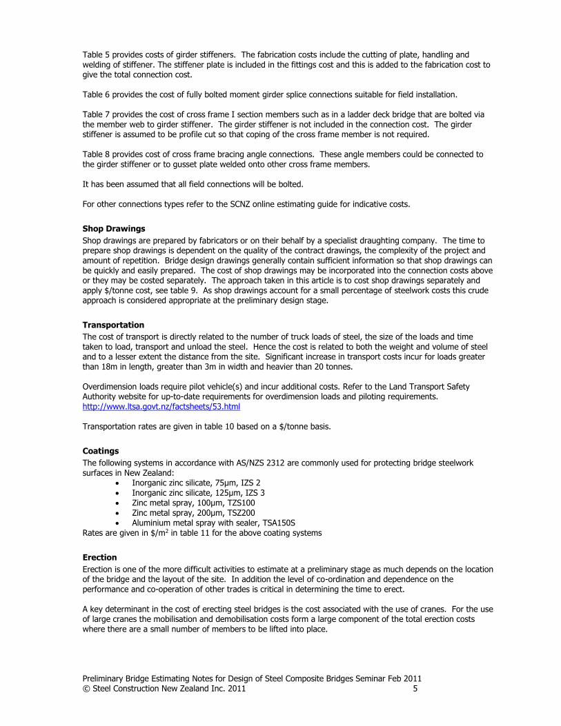
Table 5 provides costs of girder stiffeners. The fabrication costs include the cutting of plate, handling and welding of stiffener. The stiffener plate is included in the fittings cost and this is added to the fabrication cost to give the total connection cost.
Table 6 provides the cost of fully bolted moment girder splice connections suitable for field installation. Table 7 provides the cost of cross frame I section members such as in a ladder deck bridge that are bolted via the member web to girder stiffener. The girder stiffener is not included in the connection cost. The girder stiffener is assumed to be profile cut so that coping of the cross frame member is not required. Table 8 provides cost of cross frame bracing angle connections. These angle members could be connected to the girder stiffener or to gusset plate welded onto other cross frame members. It has been assumed that all field connections will be bolted. For other connections types refer to the SCNZ online estimating guide for indicative costs.
Shop Drawings
Shop drawings are prepared by fabricators or on their behalf by a specialist draughting company. The time to prepare shop drawings is dependent on the quality of the contract drawings, the complexity of the project and amount of repetition. Bridge design drawings generally contain sufficient information so that shop drawings can be quickly and easily prepared. The cost of shop drawings may be incorporated into the connection costs above or they may be costed separately. The approach taken in this article is to cost shop drawings separately and apply $/tonne cost, see table 9. As shop drawings account for a small percentage of steelwork costs this crude approach is considered appropriate at the preliminary design stage.
Transportation
The cost of transport is directly related to the number of truck loads of steel, the size of the loads and time taken to load, transport and unload the steel. Hence the cost is related to both the weight and volume of steel and to a lesser extent the distance from the site. Significant increase in transport costs incur for loads greater than 18m in length, greater than 3m in width and heavier than 20 tonnes. Overdimension loads require pilot vehicle(s) and incur additional costs. Refer to the Land Transport Safety Authority website for up-to-date requirements for overdimension loads and piloting requirements. http://www.ltsa.govt.nz/factsheets/53.html Transportation rates are given in table 10 based on a $/tonne basis.
Coatings
The following systems in accordance with AS/NZS 2312 are commonly used for protecting bridge steelwork surfaces in New Zealand:
Inorganic zinc silicate, 75µm, IZS 2 Inorganic zinc silicate, 125µm, IZS 3 Zinc metal spray, 100µm, TZS100 Zinc metal spray, 200µm, TSZ200 Aluminium metal spray with sealer, TSA150S
Rates are given in $/m2 in table 11 for the above coating systems
Erection
Erection is one of the more difficult activities to estimate at a preliminary stage as much depends on the location of the bridge and the layout of the site. In addition the level of co-ordination and dependence on the performance and co-operation of other trades is critical in determining the time to erect. A key determinant in the cost of erecting steel bridges is the cost associated with the use of cranes. For the use of large cranes the mobilisation and demobilisation costs form a large component of the total erection costs where there are a small number of members to be lifted into place.

Preliminary Bridge Estimating Notes for Design of Steel Composite Bridges Seminar Feb 2011 © Steel Construction New Zealand Inc. 2011 6
Rates are not given. A bridge contractor experienced in steel bridges may be willing to assist in estimating erection costs.
Worked Examples
Two worked examples have been prepared to illustrate the application of the estimating approach presented in this paper. The first example is a multigirder bridge, while the second is a ladder deck configuration.
Example 1 – Simply Supported Composite I Girder Bridge
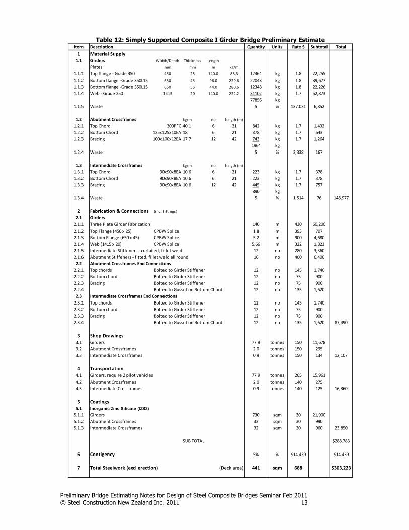
This bridge example has been taken from (Watson et al, 1996). While this bridge example is for an Australian setting the example is still useful to illustrate the steps to prepare a preliminary estimate. The bridge is shown in appendix 2 and is skewed at 15⁰ to the road alignment. The bridge spans 34.5 metres
with a width of 12.6 metres and consists of four composite plate I-beams, each weighing approximately 25 tonnes, at a spacing of 3.5 metres. The surface treatment to be applied is 75µm of inorganic zinc silicate (IZS2). Costing of the bridge Table 12 shows the estimated costs of the supply, fabrication, surface treatment of the girders and cross frames and bracing. Steel Supply The girders weight, number and lengths were calculated and the appropriate rate applied. This was similarly done for cross frame bracing. A 5% wastage factor was allowed for trimming the plates and for the waste involved in profiling the web to provide the specified camber. A 5% wastage factor was also allowed for hot rolled sections. Fabrication The fabrication costs of the girders, cross frame bracing were quickly and simply obtained from the relevant tables. An allowance was made for shop drawings. The amount is not significant. The girders between the piers are greater than 18m in length and so require pilot vehicles and will have
increased transport costs. Surface Treatment The surface areas were readily determined and the appropriate rates for inorganic zinc silicate applied
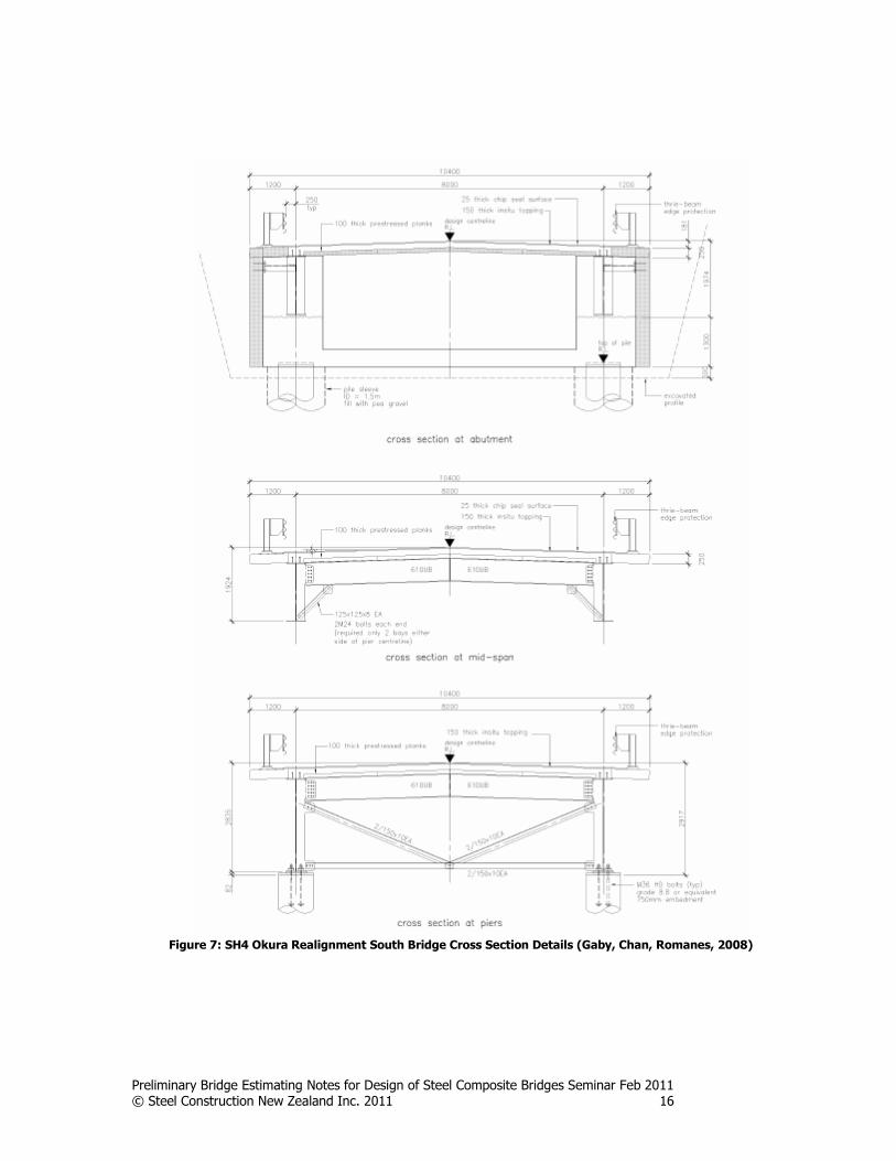
Example 2 – SH4 Okura Realignment South Bridge
This is a 3 span ladder deck bridge 96m long. Details of this bridge can be found in (Gaby, Chan and Romanes, 2008) Costing of the bridge Table 9 shows the estimated costs of the supply, fabrication, surface treatment of the girders and cross frames and bracing. Steel Supply The girder weight, number and lengths were calculated and the appropriate rate applied. This was similarly done for cross frame bracing and horizontal bracing. A 5% wastage factor was allowed for trimming the plates. Pier girder webs are tapered. This could increase wastage component however it is assumed a computer nesting program is used and the girder web plate could also be used for connection cleats. A 5% wastage factor was also allowed for hot rolled sections. Fabrication The fabrication costs of the girders, cross frames and bracing were quickly and simply obtained from the relevant tables. Span girders lengths are greater than 18m and so will exceed maximum available plate lengths. Therefore an allowance is made for complete penetration butt weld of span girder plates. An allowance was made for shop drawings. The amount is not significant.

Preliminary Bridge Estimating Notes for Design of Steel Composite Bridges Seminar Feb 2011 © Steel Construction New Zealand Inc. 2011 7
As the span girders are greater than 18m in length, pilot vehicles are required and this will increase transport costs.
Surface Treatment The surface areas were readily determined and the appropriate rates for inorganic zinc silicate applied. Overall Cost Comparison The steel option was being considered as an alternative to a concrete superstructure. Savings in substructure costs are significant and should be included in any cost comparison. Due to the lighter superstructure weight of a composite steel/concrete option instead of a concrete option, the cost savings in the foundations and columns amounted to a saving of close to $400/m2 of decking area (El Sarraf, 2009).
Conclusion
This article presents a simple method for developing preliminary estimates of steel bridge superstructure costs for traditional multi girder (I sections) and ladder deck bridges based on limited design information. This will be of assistance to engineers in evaluating different steel options and also in material selection choice. The rates provided in this article are for estimating purposes only and do not necessarily reflect the current market rates. Steel bridge fabricators and constructors should be consulted to provide input into the design details of the
bridge and will be able to provide up to date rates. The steel bridge superstructure fabrication cost is only a portion of the overall cost of a bridge project. The weight savings of a steel-concrete composite bridge may result in significantly reduction in substructure costs. The ease and speed of erection of a steel bridge are also has significant advantages over alternate material options.
References
AS/NZS 2312:2002/2004, Guide to the Protection of Structural Steel against Atmospheric Corrosion by the Use of Protective Coatings, incorporating Amendment No 1:2004. Standards New Zealand, Wellington El Sarraf, R., Economical Steel Bridge Solutions for New Zealand, SESOC Journal Vol 21 No 2 Vol 2 2009 Gaby, P, Chan, M and Romanes, M; Okura Ladder Deck Bridges, Conference Proceedings of the Metal’s Industry Conference, HERA, Manukau City, New Zealand. 2008 Hayward, A., Sadler, N., Tordoff, D., Steel bridges – A Practical Approach to Design for Efficient fabrication and Construction, The British Constructional Steelwork Association Ltd, London, 2002 HERA, Steel Bridges for New Zealand A 1 Day Seminar for bridge Design Engineers, Contractors and Specifiers, HERA Report R4-130, New Zealand Heavy Engineering Research Association, Manukau City, New Zealand, 2004 SCNZ, Online Estimation Guide, accessed on the website www.scnz.org Watson, K., B., Dallas, S., van der Kreek, N., Main, T., Costing of steelwork from feasibility through to completion, Steel Construction volume 30 Number 2, Australian Institute of Steel Construction, June 1996

Preliminary Bridge Estimating Notes for Design of Steel Composite Bridges Seminar Feb 2011 © Steel Construction New Zealand Inc. 2011 8
Appendix 1: Bridge Preliminary Estimating Rates
Supply Rates Table 1: Plate Indent Supply
Grade $/kg
250 1.70
300 1.70
300L0 1.70
300L15 1.70
350 1.80
350L10 1.80
350L15 1.80
1) For weathering steel add $0.4/kg 2) For charpy testing add $0.05/kg
Table 2: Section Supply
Section Indent $/kg
Ex-stock $/kg
Universal Beams (UB) G300 1.70 2.00
Angles (EA, UA) G300 1.70 2.00
Structural Hollow Sections (CHS, RHS, SHS) 2.40 2.80
1) For weathering steel add $0.4/kg 2) For charpy testing add $0.05/kg

Preliminary Bridge Estimating Notes for Design of Steel Composite Bridges Seminar Feb 2011 © Steel Construction New Zealand Inc. 2011 9
Fabrication Rates General Notes:
1) CFW: Continuous Fillet Weld 2) CPBW: Complete Penetration Butt Weld
Table 3: Three Plate Girder Fabrication Rates
Section Mass kg/m
Cost $/m
315 to 455 380
455.1 to 700 430
700.1 to 1000 490
Note: Stripping, handling, assembly, CFW (8mm) to web/flanges, Non destruction testing of welds
Table 4: CPBW Splice Rates for Girder Flanges/Webs
Plate thickness
mm
Cost
$/m
6 115
10 177
16 234
25 393
40 750
50 1050
60 1400
70 1800
80 2300
Table 5: Girder Stiffeners Connection Rates
Stiffeners Section Mass
kg/m
Fitted Stiffener Butt welded ends
$
Fitted Stiffener Fillet welded
$
Curtailed Stiffener Both ends
$
Curtailed Stiffener Single end
$
Fabricate Fittings Total Fabricate Fittings Total Fabricate Fittings Total Fabricate Fittings Total
315 to 455
440 70 510 250 70 320 150 70 220 200 70 270
455.1 to 700
550 90 640 310 90 400 190 90 280 250 90 340
700.1 to 1000
650 110 760 370 110 480 230 110 340 300 110 410
Diagram
Comments Cut & weld
Flange CPBW / Web CFW
Cut & Weld Flange/Web CFW
Cut & Weld Web CFW
Cut & Weld Flange/Web CFW
Note: CPBW costs are based on 16mm thick stiffener. CFW are based on 6mm CFW

Preliminary Bridge Estimating Notes for Design of Steel Composite Bridges Seminar Feb 2011 © Steel Construction New Zealand Inc. 2011 10
Table 6: Girder Splice Connection Rates
Connection 100% Moment Capacity Splice
Section Mass kg/m
Fully Bolted $
Fabrication Fittings Total
315 to 455 1200 800 2000
455.1 to 700 1700 1300 3000
700.1 to 1000 2200 1800 4000
Diagram
Comments: Cut plates & beams, drill/punch
holes, web splice plates each side
Table 7: Cross Frame I Sections End Connections
Connection Bolted to Girder Stiffener
Section Mass kg/m
$
Fabrication Fittings Total
<60.5 120 25 145
60.6 to 160 155 40 195
Diagram
Comments: Cut beam, drill/punch holes, web plate
not included - see girder stiffeners
Table 8: Cross Frame Bracing Angle Connection Rates
Connection Bolted to Girder Stiffener Bolted to Gussets Welded to Gussets
Section Mass kg/m
$
$
$
Fabrication Fittings Total Fabrication Fittings Total Fabrication Fittings Total
<30 65 10 75 120 15 135 130 5 135
Diagram
Comments: Cut beam, drill/punch holes, web plate not included - see girder stiffeners
Cut bracing member and gusset, drill/punch holes, CFW gusset to other members
Cut bracing member and gusset, CFW to gusset, CFW gusset to other members

Preliminary Bridge Estimating Notes for Design of Steel Composite Bridges Seminar Feb 2011 © Steel Construction New Zealand Inc. 2011 11
Other Rates Table 9: Shop Drawing Rates
Shop Drawings Per tonne
High standard of contract drawings 150
Table 10: Transportation Rates
Transport Per tonne
Unescorted (min 5 tonnes/ delivery) 140 One Pilot Vehicle 175 Two Pilot Vehicle 205
Assumptions:
1. 6 hr round trip for the distance less than or equal to 50 km from fabrication shop 2. 2.5 hr round trip for pilot vehicle accompanying loads. 3. Rates includes an allowance of $10 per tonne for loading and unloading. 4. Rates includes fabricator's margin.
Table 11: Coating Rates
Coating AS/NZS 2312:2004 System Rate
$/sqm Inorganic Zinc Silicate 75µm IZS 2 (solvent borne) 30 Inorganic Zinc Silicate 125µm IZS 3 (solvent borne) 40
Zinc Metal Spray 100µm TSZ100 60 Zinc Metal Spray 200µm TSZ200 70
Aluminium Metal Spray with sealer TSA150S 140 $/steel kg
Hot dipped galvanised HDG600 1.60

Preliminary Bridge Estimating Notes for Design of Steel Composite Bridges Seminar Feb 2011 © Steel Construction New Zealand Inc. 2011 12
Appendix 2: Simply Supported Composite I Girder Bridge
Figure 5: Simply Supported Composite I Girder Bridge Details (Watson et al, 1996)
Preliminary Bridge Estimating Notes for Design of Steel Composite Bridges Seminar Feb 2011 © Steel Construction New Zealand Inc. 2011 13
Table 12: Simply Supported Composite I Girder Bridge Preliminary Estimate Item Description Quantity Units Rate $ Subtotal Total
1 Material Supply
1.1 Girders Width/Depth Thickness Length
Plates mm mm m kg/m
1.1.1 Top flange - Grade 350 450 25 140.0 88.3 12364 kg 1.8 22,255
1.1.2 Bottom flange -Grade 350L15 650 45 96.0 229.6 22043 kg 1.8 39,677
1.1.3 Bottom flange -Grade 350L15 650 55 44.0 280.6 12348 kg 1.8 22,226
1.1.4 Web - Grade 250 1415 20 140.0 222.2 31102 kg 1.7 52,873
77856 kg
1.1.5 Waste 5 % 137,031 6,852
1.2 Abutment Crossframes kg/m no length (m)
1.2.1 Top Chord 300PFC 40.1 6 21 842 kg 1.7 1,432
1.2.2 Bottom Chord 125x125x10EA 18 6 21 378 kg 1.7 643
1.2.3 Bracing 100x100x12EA 17.7 12 42 743 kg 1.7 1,264
1964 kg
1.2.4 Waste 5 % 3,338 167
1.3 Intermediate Crossframes kg/m no length (m)
1.3.1 Top Chord 90x90x8EA 10.6 6 21 223 kg 1.7 378
1.3.2 Bottom Chord 90x90x8EA 10.6 6 21 223 kg 1.7 378
1.3.3 Bracing 90x90x8EA 10.6 12 42 445 kg 1.7 757
890 kg
1.3.4 Waste 5 % 1,514 76 148,977
2 Fabrication & Connections (incl fittings)
2.1 Girders
2.1.1 Three Plate Girder Fabrication 140 m 430 60,200
2.1.2 Top Flange (450 x 25) CPBW Splice 1.8 m 393 707
2.1.3 Bottom Flange (650 x 45) CPBW Splice 5.2 m 900 4,680
2.1.4 Web (1415 x 20) CPBW Splice 5.66 m 322 1,823
2.1.5 Intermediate Stiffeners - curtailed, fillet weld 12 no 280 3,360
2.1.6 Abutment Stiffeners - fitted, fillet weld all round 16 no 400 6,400
2.2 Abutment Crossframes End Connections
2.2.1 Top chords Bolted to Girder Stiffener 12 no 145 1,740
2.2.2 Bottom chord Bolted to Girder Stiffener 12 no 75 900
2.2.3 Bracing Bolted to Girder Stiffener 12 no 75 900
2.2.4 Bolted to Gusset on Bottom Chord 12 no 135 1,620
2.3 Intermediate Crossframes End Connections
2.3.1 Top chords Bolted to Girder Stiffener 12 no 145 1,740
2.3.2 Bottom chord Bolted to Girder Stiffener 12 no 75 900
2.3.3 Bracing Bolted to Girder Stiffener 12 no 75 900
2.3.4 Bolted to Gusset on Bottom Chord 12 no 135 1,620 87,490
3 Shop Drawings
3.1 Girders 77.9 tonnes 150 11,678
3.2 Abutment Crossframes 2.0 tonnes 150 295
3.3 Intermediate Crossframes 0.9 tonnes 150 134 12,107
4 Transportation
4.1 Girders, require 2 pilot vehicles 77.9 tonnes 205 15,961
4.2 Abutment Crossframes 2.0 tonnes 140 275
4.3 Intermediate Crossframes 0.9 tonnes 140 125 16,360
5 Coatings
5.1 Inorganic Zinc Silicate (IZS2)
5.1.1 Girders 730 sqm 30 21,900
5.1.2 Abutment Crossframes 33 sqm 30 990
5.1.3 Intermediate Crossframes 32 sqm 30 960 23,850
SUB TOTAL $288,783
6 Contigency 5% % $14,439 $14,439
7 Total Steelwork (excl erection) (Deck area) 441 sqm 688 $303,223
Preliminary Bridge Estimating Notes for Design of Steel Composite Bridges Seminar Feb 2011 © Steel Construction New Zealand Inc. 2011 14
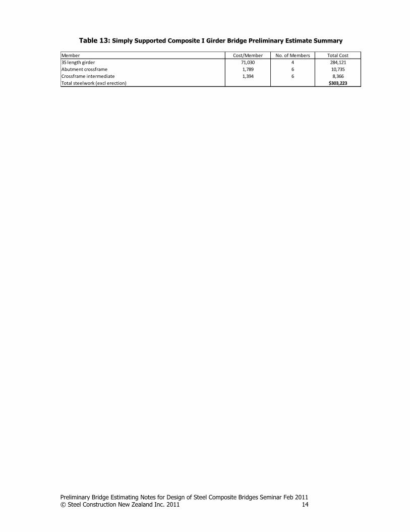
Table 13: Simply Supported Composite I Girder Bridge Preliminary Estimate Summary
Member
35 length girder
Abutment crossframe
Crossframe intermediate
Total steelwork (excl erection)
8,366
$303,223
71,030
1,789
1,394
4
6
6
Cost/Member No. of Members Total Cost
284,121
10,735

Preliminary Bridge Estimating Notes for Design of Steel Composite Bridges Seminar Feb 2011 © Steel Construction New Zealand Inc. 2011 15
Appendix 2: SH4 Okura Realignment South Bridge
Figure 6: SH4 Okura Realignment South Bridge Plan and Elevation Details (Gaby, Chan, Romanes, 2008)
Preliminary Bridge Estimating Notes for Design of Steel Composite Bridges Seminar Feb 2011 © Steel Construction New Zealand Inc. 2011 16
Figure 7: SH4 Okura Realignment South Bridge Cross Section Details (Gaby, Chan, Romanes, 2008)

Preliminary Bridge Estimating Notes for Design of Steel Composite Bridges Seminar Feb 2011 © Steel Construction New Zealand Inc. 2011 17
Table 14: SH4 Okura Realignment South Bridge Preliminary Estimate Item Description Quantity Units Rate $ Subtotal Total
1 Material Supply1.1 Girders Width/Depth Thickness Length
Span Girder mm mm m kg/m
1.1.1 Top flange - Grade 350 500 16 144.0 62.8 9043 kg 1.8 16,278
1.1.2 Bottom flange - Grade 350 500 25 144.0 98.1 14130 kg 1.8 25,434
1.1.3 Web - Grade 350 1480 12 144.0 139.4 20076 kg 1.8 36,137
300.3 43249 kg
1.1.4 Waste 5 % 77,848 3,892
Pier Girder
1.1.5 Top flange - Grade 350 500 20 48 78.5 3768 kg 1.8 6,782
1.1.6 Bottom flange - Grade 350 500 32 48.56 125.6 6099 kg 1.8 10,978
1.1.7 Web (depth varies) - Grade 350 1977 12 48 186.2 8939 kg 1.8 16,091
390.3 18806 kg
1.1.8 Waste 5 % 33,851 1,693
1.2 Transoms and Bracing kg/m no length (m)
1.2.1 Transoms 610UB 101 48 192 19392 kg 1.7 32,966
1.2.2 Bracing at Piers 150x10 EA 21.9 24 132.8 2908 kg 1.7 4,944
1.2.3 Transom Bracing 125x8 EA 14.9 16 24 358 kg 1.7 608
1.2.4 Horiz Bracing 125x8 EA 14.9 20 112 1669 kg 1.7 2,837
1.2.5 Edge Panel Supports CWB 39 48 50.4 1966 kg 2.75 5,405
26292 kg
Waste 5 % 46,761 2,338 166,384
2 Fabrication & Connections (incl fittings)
2.1 Girders
2.1.1 Three Plate Girder Fabrication Span Girder 144 m 380 54,720
2.1.2 Pier Girder 48 m 380 18,240
2.1.3 Span Girder Top Flange (500x16) CPBW 3.0 m 115 345
2.1.4 Span Girder Bottom Flange (500x25) CPBW 3.0 m 393 1,179
2.1.5 Span Girder Web (1480x12) CPBW 8.9 m 196 1,740
2.1.6 Bolted Girder Splice 8 no 2000 16,000
2.1.7 Span Girder Stiffeners - fitted, fillet all round 26 no 320 8,320
2.1.8 Pier Girder Stiffeners - fitted, fillet all round 22 no 320 7,040
2.2 Transom and Bracing Connections
2.2.1 Transoms Bolted to Girder Stiffener 48 no 195 9,360
2.2.2 Welded Moment 48 no 450 21,600
2.2.3 Bracing at Piers Bolted to Girder Stiffener 24 no 75 1,800
2.2.4 Bolted to Gussetts 24 no 135 3,240
2.2.5 Transom Bracing Bolted to Girder Stiffener 16 no 75 1,200
2.2.6 Bolted to Gussetts 16 no 135 2,160
2.2.7 Horiz Bracing Bolted to Gussetts 40 no 135 5,400
2.2.8 Edge Panel Supports Welded Moment 48 no 200 9,600 161,944
3 Shop Drawings 88 tonnes 150 13,252 13,252
4 Transportation
4.1 Span Girders, require 2 pilot vehicles 43.2 tonnes 205 8,866
4.2 Pier Girders 18.8 tonnes 140 2,633
4.3 Transoms and Bracing 26.3 tonnes 140 3,681 15,180
5 Coatings
5.1 Inorganic Zinc Silicate (IZS3) sqm/m
5.1.1 Span Girder 5.02 723 sqm 40 28,904
5.1.2 Pier Girder 6.03 290 sqm 40 11,585
5.1.3 Transoms 610UB 101 1.84 353 sqm 40 14,131
5.1.4 Bracing at Piers 150x10 EA 21.9 0.59 78 sqm 40 3,134
5.1.5 Transom Bracing 125x8 EA 14.9 0.491 12 sqm 40 471
5.1.6 Horiz Bracing 125x8 EA 14.9 0.491 55 sqm 40 2,200
5.1.7 Edge Panel Supports CWB 39 0.7 35 sqm 40 1,411
5.1.8 Girder stiffeners 36 sqm 40 1,440 $63,276
SUB TOTAL $420,037
6 Contigency 5% % $21,002 $21,002
7 Total Fabrication (Deck area) 966 sqm 457 $441,038