Embed Size (px)
Citation preview

I N S T A L L A T I O N / O P E R A T I O N
C307M-L (3/10)
ES30C/ES31CES30PC/ES31PC
ES30/ES31 SeriesEsprit® with IOC/IOP

Contents
Important Safety Instructions . . . . . . . . . . . . . . . . . . . . . . . . . . . . . . . . . . . . . . . . . . . . . . . . . . . . . . . . . . . . . . . . . . . . . . . . . . . . . . . . . . . . . . . . . . . . 4
Important Notices . . . . . . . . . . . . . . . . . . . . . . . . . . . . . . . . . . . . . . . . . . . . . . . . . . . . . . . . . . . . . . . . . . . . . . . . . . . . . . . . . . . . . . . . . . . . . . . . . . . . . 5Regulatory Notice . . . . . . . . . . . . . . . . . . . . . . . . . . . . . . . . . . . . . . . . . . . . . . . . . . . . . . . . . . . . . . . . . . . . . . . . . . . . . . . . . . . . . . . . . . . . . . . . . 5
Description. . . . . . . . . . . . . . . . . . . . . . . . . . . . . . . . . . . . . . . . . . . . . . . . . . . . . . . . . . . . . . . . . . . . . . . . . . . . . . . . . . . . . . . . . . . . . . . . . . . . . . . . . . . 6ES30C/ES31C Series Esprit with IOP . . . . . . . . . . . . . . . . . . . . . . . . . . . . . . . . . . . . . . . . . . . . . . . . . . . . . . . . . . . . . . . . . . . . . . . . . . . . . . . . . . 6
Models . . . . . . . . . . . . . . . . . . . . . . . . . . . . . . . . . . . . . . . . . . . . . . . . . . . . . . . . . . . . . . . . . . . . . . . . . . . . . . . . . . . . . . . . . . . . . . . . . . . . . 6ES30PC/ES31PC Esprit with Pressurized IOC . . . . . . . . . . . . . . . . . . . . . . . . . . . . . . . . . . . . . . . . . . . . . . . . . . . . . . . . . . . . . . . . . . . . . . . . . . . . 7
Models . . . . . . . . . . . . . . . . . . . . . . . . . . . . . . . . . . . . . . . . . . . . . . . . . . . . . . . . . . . . . . . . . . . . . . . . . . . . . . . . . . . . . . . . . . . . . . . . . . . . . 7
Installation . . . . . . . . . . . . . . . . . . . . . . . . . . . . . . . . . . . . . . . . . . . . . . . . . . . . . . . . . . . . . . . . . . . . . . . . . . . . . . . . . . . . . . . . . . . . . . . . . . . . . . . . . . . 8
Optional TXB Series Translator Board Installation . . . . . . . . . . . . . . . . . . . . . . . . . . . . . . . . . . . . . . . . . . . . . . . . . . . . . . . . . . . . . . . . . . . . . . . . . . . 12How to Remove the Pan/Tilt Cover . . . . . . . . . . . . . . . . . . . . . . . . . . . . . . . . . . . . . . . . . . . . . . . . . . . . . . . . . . . . . . . . . . . . . . . . . . . . . . . . . . 12How to Reinstall the Pan/Tilt Cover. . . . . . . . . . . . . . . . . . . . . . . . . . . . . . . . . . . . . . . . . . . . . . . . . . . . . . . . . . . . . . . . . . . . . . . . . . . . . . . . . . 12
Operation . . . . . . . . . . . . . . . . . . . . . . . . . . . . . . . . . . . . . . . . . . . . . . . . . . . . . . . . . . . . . . . . . . . . . . . . . . . . . . . . . . . . . . . . . . . . . . . . . . . . . . . . . . . 14Power-Up Display . . . . . . . . . . . . . . . . . . . . . . . . . . . . . . . . . . . . . . . . . . . . . . . . . . . . . . . . . . . . . . . . . . . . . . . . . . . . . . . . . . . . . . . . . . . . . . . . 14How to Operate Your System . . . . . . . . . . . . . . . . . . . . . . . . . . . . . . . . . . . . . . . . . . . . . . . . . . . . . . . . . . . . . . . . . . . . . . . . . . . . . . . . . . . . . . . 14Preset 95: Accessing Main Menu. . . . . . . . . . . . . . . . . . . . . . . . . . . . . . . . . . . . . . . . . . . . . . . . . . . . . . . . . . . . . . . . . . . . . . . . . . . . . . . . . . . . 14
CM6700/CM6800 . . . . . . . . . . . . . . . . . . . . . . . . . . . . . . . . . . . . . . . . . . . . . . . . . . . . . . . . . . . . . . . . . . . . . . . . . . . . . . . . . . . . . . . . . . . 14KBD200A/KBD300A: Direct Mode Only . . . . . . . . . . . . . . . . . . . . . . . . . . . . . . . . . . . . . . . . . . . . . . . . . . . . . . . . . . . . . . . . . . . . . . . . . . 15CM9500 . . . . . . . . . . . . . . . . . . . . . . . . . . . . . . . . . . . . . . . . . . . . . . . . . . . . . . . . . . . . . . . . . . . . . . . . . . . . . . . . . . . . . . . . . . . . . . . . . . . 15CM9740/CM9760/CM9770/CM9780 . . . . . . . . . . . . . . . . . . . . . . . . . . . . . . . . . . . . . . . . . . . . . . . . . . . . . . . . . . . . . . . . . . . . . . . . . . . . 15KBD4000/KBD4002/KBD4000V . . . . . . . . . . . . . . . . . . . . . . . . . . . . . . . . . . . . . . . . . . . . . . . . . . . . . . . . . . . . . . . . . . . . . . . . . . . . . . . . . 15MPT9500 . . . . . . . . . . . . . . . . . . . . . . . . . . . . . . . . . . . . . . . . . . . . . . . . . . . . . . . . . . . . . . . . . . . . . . . . . . . . . . . . . . . . . . . . . . . . . . . . . . 15Endura Systems . . . . . . . . . . . . . . . . . . . . . . . . . . . . . . . . . . . . . . . . . . . . . . . . . . . . . . . . . . . . . . . . . . . . . . . . . . . . . . . . . . . . . . . . . . . . . 15
Operating Notes . . . . . . . . . . . . . . . . . . . . . . . . . . . . . . . . . . . . . . . . . . . . . . . . . . . . . . . . . . . . . . . . . . . . . . . . . . . . . . . . . . . . . . . . . . . . . . . . . 16Environmental Range. . . . . . . . . . . . . . . . . . . . . . . . . . . . . . . . . . . . . . . . . . . . . . . . . . . . . . . . . . . . . . . . . . . . . . . . . . . . . . . . . . . . . . . . . 16Pan/Tilt Functions . . . . . . . . . . . . . . . . . . . . . . . . . . . . . . . . . . . . . . . . . . . . . . . . . . . . . . . . . . . . . . . . . . . . . . . . . . . . . . . . . . . . . . . . . . . 16Scan Speed . . . . . . . . . . . . . . . . . . . . . . . . . . . . . . . . . . . . . . . . . . . . . . . . . . . . . . . . . . . . . . . . . . . . . . . . . . . . . . . . . . . . . . . . . . . . . . . . 16Preset Functions. . . . . . . . . . . . . . . . . . . . . . . . . . . . . . . . . . . . . . . . . . . . . . . . . . . . . . . . . . . . . . . . . . . . . . . . . . . . . . . . . . . . . . . . . . . . . 16Random, Frame, and Auto Scanning . . . . . . . . . . . . . . . . . . . . . . . . . . . . . . . . . . . . . . . . . . . . . . . . . . . . . . . . . . . . . . . . . . . . . . . . . . . . . 16Zones . . . . . . . . . . . . . . . . . . . . . . . . . . . . . . . . . . . . . . . . . . . . . . . . . . . . . . . . . . . . . . . . . . . . . . . . . . . . . . . . . . . . . . . . . . . . . . . . . . . . . 16Patterns . . . . . . . . . . . . . . . . . . . . . . . . . . . . . . . . . . . . . . . . . . . . . . . . . . . . . . . . . . . . . . . . . . . . . . . . . . . . . . . . . . . . . . . . . . . . . . . . . . . 17Park . . . . . . . . . . . . . . . . . . . . . . . . . . . . . . . . . . . . . . . . . . . . . . . . . . . . . . . . . . . . . . . . . . . . . . . . . . . . . . . . . . . . . . . . . . . . . . . . . . . . . . 17IR Filter. . . . . . . . . . . . . . . . . . . . . . . . . . . . . . . . . . . . . . . . . . . . . . . . . . . . . . . . . . . . . . . . . . . . . . . . . . . . . . . . . . . . . . . . . . . . . . . . . . . . 17Auto Iris . . . . . . . . . . . . . . . . . . . . . . . . . . . . . . . . . . . . . . . . . . . . . . . . . . . . . . . . . . . . . . . . . . . . . . . . . . . . . . . . . . . . . . . . . . . . . . . . . . . 17Wiper . . . . . . . . . . . . . . . . . . . . . . . . . . . . . . . . . . . . . . . . . . . . . . . . . . . . . . . . . . . . . . . . . . . . . . . . . . . . . . . . . . . . . . . . . . . . . . . . . . . . . 17Open Collector Auxiliary Output . . . . . . . . . . . . . . . . . . . . . . . . . . . . . . . . . . . . . . . . . . . . . . . . . . . . . . . . . . . . . . . . . . . . . . . . . . . . . . . . 17
Operating Notes: Pressurized Models only . . . . . . . . . . . . . . . . . . . . . . . . . . . . . . . . . . . . . . . . . . . . . . . . . . . . . . . . . . . . . . . . . . . . . . . . . . . . 18Pressurized Integrated Optics Cartridge . . . . . . . . . . . . . . . . . . . . . . . . . . . . . . . . . . . . . . . . . . . . . . . . . . . . . . . . . . . . . . . . . . . . . . . . . . 18Alert Label Cycle . . . . . . . . . . . . . . . . . . . . . . . . . . . . . . . . . . . . . . . . . . . . . . . . . . . . . . . . . . . . . . . . . . . . . . . . . . . . . . . . . . . . . . . . . . . . 18Alert Reset . . . . . . . . . . . . . . . . . . . . . . . . . . . . . . . . . . . . . . . . . . . . . . . . . . . . . . . . . . . . . . . . . . . . . . . . . . . . . . . . . . . . . . . . . . . . . . . . . 19Current Reading Menu. . . . . . . . . . . . . . . . . . . . . . . . . . . . . . . . . . . . . . . . . . . . . . . . . . . . . . . . . . . . . . . . . . . . . . . . . . . . . . . . . . . . . . . . 19
ES30C22/ES31C22 Menu Tree . . . . . . . . . . . . . . . . . . . . . . . . . . . . . . . . . . . . . . . . . . . . . . . . . . . . . . . . . . . . . . . . . . . . . . . . . . . . . . . . . . . . . . . . . . 20
ES30CBW24/ES31CBW24 Menu Tree . . . . . . . . . . . . . . . . . . . . . . . . . . . . . . . . . . . . . . . . . . . . . . . . . . . . . . . . . . . . . . . . . . . . . . . . . . . . . . . . . . . . 21
ES30CBW35/ES31CBW35 Menu Tree . . . . . . . . . . . . . . . . . . . . . . . . . . . . . . . . . . . . . . . . . . . . . . . . . . . . . . . . . . . . . . . . . . . . . . . . . . . . . . . . . . . . 22
ES30PC22/ES31PC22 Menu Tree . . . . . . . . . . . . . . . . . . . . . . . . . . . . . . . . . . . . . . . . . . . . . . . . . . . . . . . . . . . . . . . . . . . . . . . . . . . . . . . . . . . . . . . . 23
ES30PCBW24/ES31PCBW24 Menu Tree . . . . . . . . . . . . . . . . . . . . . . . . . . . . . . . . . . . . . . . . . . . . . . . . . . . . . . . . . . . . . . . . . . . . . . . . . . . . . . . . . . 24
ES30PCBW35/ES31PCBW35 Menu Tree . . . . . . . . . . . . . . . . . . . . . . . . . . . . . . . . . . . . . . . . . . . . . . . . . . . . . . . . . . . . . . . . . . . . . . . . . . . . . . . . . . 25
Configuration . . . . . . . . . . . . . . . . . . . . . . . . . . . . . . . . . . . . . . . . . . . . . . . . . . . . . . . . . . . . . . . . . . . . . . . . . . . . . . . . . . . . . . . . . . . . . . . . . . . . . . . . 26
2 C307M-L (3/10)

ACK Act. . . . . . . . . . . . . . . . . . . . . . . . . . . . . . . . . . . . . . . . . . . . . . . . . . . . . . . . . . . . . . . . . . . . . . . . . . . . . . . . . . . . . . . . . . . . . . . . . . . . . . . . 26Alert Display Position . . . . . . . . . . . . . . . . . . . . . . . . . . . . . . . . . . . . . . . . . . . . . . . . . . . . . . . . . . . . . . . . . . . . . . . . . . . . . . . . . . . . . . . . . . . . . 27Alert Display Row . . . . . . . . . . . . . . . . . . . . . . . . . . . . . . . . . . . . . . . . . . . . . . . . . . . . . . . . . . . . . . . . . . . . . . . . . . . . . . . . . . . . . . . . . . . . . . . . 28Alert Repeat . . . . . . . . . . . . . . . . . . . . . . . . . . . . . . . . . . . . . . . . . . . . . . . . . . . . . . . . . . . . . . . . . . . . . . . . . . . . . . . . . . . . . . . . . . . . . . . . . . . . 29Auto Focus Mode . . . . . . . . . . . . . . . . . . . . . . . . . . . . . . . . . . . . . . . . . . . . . . . . . . . . . . . . . . . . . . . . . . . . . . . . . . . . . . . . . . . . . . . . . . . . . . . . 30Auto Iris. . . . . . . . . . . . . . . . . . . . . . . . . . . . . . . . . . . . . . . . . . . . . . . . . . . . . . . . . . . . . . . . . . . . . . . . . . . . . . . . . . . . . . . . . . . . . . . . . . . . . . . . 31Auto IR Level. . . . . . . . . . . . . . . . . . . . . . . . . . . . . . . . . . . . . . . . . . . . . . . . . . . . . . . . . . . . . . . . . . . . . . . . . . . . . . . . . . . . . . . . . . . . . . . . . . . . 32Auto Sharpness. . . . . . . . . . . . . . . . . . . . . . . . . . . . . . . . . . . . . . . . . . . . . . . . . . . . . . . . . . . . . . . . . . . . . . . . . . . . . . . . . . . . . . . . . . . . . . . . . . 33Az/El . . . . . . . . . . . . . . . . . . . . . . . . . . . . . . . . . . . . . . . . . . . . . . . . . . . . . . . . . . . . . . . . . . . . . . . . . . . . . . . . . . . . . . . . . . . . . . . . . . . . . . . . . . 34Az/El Line . . . . . . . . . . . . . . . . . . . . . . . . . . . . . . . . . . . . . . . . . . . . . . . . . . . . . . . . . . . . . . . . . . . . . . . . . . . . . . . . . . . . . . . . . . . . . . . . . . . . . . 35Azimuth Zero. . . . . . . . . . . . . . . . . . . . . . . . . . . . . . . . . . . . . . . . . . . . . . . . . . . . . . . . . . . . . . . . . . . . . . . . . . . . . . . . . . . . . . . . . . . . . . . . . . . . 36Backlight Compensation . . . . . . . . . . . . . . . . . . . . . . . . . . . . . . . . . . . . . . . . . . . . . . . . . . . . . . . . . . . . . . . . . . . . . . . . . . . . . . . . . . . . . . . . . . . 37Direction . . . . . . . . . . . . . . . . . . . . . . . . . . . . . . . . . . . . . . . . . . . . . . . . . . . . . . . . . . . . . . . . . . . . . . . . . . . . . . . . . . . . . . . . . . . . . . . . . . . . . . . 38Direction Line . . . . . . . . . . . . . . . . . . . . . . . . . . . . . . . . . . . . . . . . . . . . . . . . . . . . . . . . . . . . . . . . . . . . . . . . . . . . . . . . . . . . . . . . . . . . . . . . . . . 39Display Duration . . . . . . . . . . . . . . . . . . . . . . . . . . . . . . . . . . . . . . . . . . . . . . . . . . . . . . . . . . . . . . . . . . . . . . . . . . . . . . . . . . . . . . . . . . . . . . . . . 40Field Alignment. . . . . . . . . . . . . . . . . . . . . . . . . . . . . . . . . . . . . . . . . . . . . . . . . . . . . . . . . . . . . . . . . . . . . . . . . . . . . . . . . . . . . . . . . . . . . . . . . . 41Gain Limit . . . . . . . . . . . . . . . . . . . . . . . . . . . . . . . . . . . . . . . . . . . . . . . . . . . . . . . . . . . . . . . . . . . . . . . . . . . . . . . . . . . . . . . . . . . . . . . . . . . . . . 42Image Stabilizer . . . . . . . . . . . . . . . . . . . . . . . . . . . . . . . . . . . . . . . . . . . . . . . . . . . . . . . . . . . . . . . . . . . . . . . . . . . . . . . . . . . . . . . . . . . . . . . . . 43IR Filter Mode . . . . . . . . . . . . . . . . . . . . . . . . . . . . . . . . . . . . . . . . . . . . . . . . . . . . . . . . . . . . . . . . . . . . . . . . . . . . . . . . . . . . . . . . . . . . . . . . . . . 44Limit Stops . . . . . . . . . . . . . . . . . . . . . . . . . . . . . . . . . . . . . . . . . . . . . . . . . . . . . . . . . . . . . . . . . . . . . . . . . . . . . . . . . . . . . . . . . . . . . . . . . . . . . 45
Turning Limit Stops On or Off . . . . . . . . . . . . . . . . . . . . . . . . . . . . . . . . . . . . . . . . . . . . . . . . . . . . . . . . . . . . . . . . . . . . . . . . . . . . . . . . . . 45Programming Limit Stops. . . . . . . . . . . . . . . . . . . . . . . . . . . . . . . . . . . . . . . . . . . . . . . . . . . . . . . . . . . . . . . . . . . . . . . . . . . . . . . . . . . . . . 45
Line Synchronization. . . . . . . . . . . . . . . . . . . . . . . . . . . . . . . . . . . . . . . . . . . . . . . . . . . . . . . . . . . . . . . . . . . . . . . . . . . . . . . . . . . . . . . . . . . . . . 47LowLight Focus . . . . . . . . . . . . . . . . . . . . . . . . . . . . . . . . . . . . . . . . . . . . . . . . . . . . . . . . . . . . . . . . . . . . . . . . . . . . . . . . . . . . . . . . . . . . . . . . . . 48LowLight Limit. . . . . . . . . . . . . . . . . . . . . . . . . . . . . . . . . . . . . . . . . . . . . . . . . . . . . . . . . . . . . . . . . . . . . . . . . . . . . . . . . . . . . . . . . . . . . . . . . . . 49Low Lux Noise Reduction . . . . . . . . . . . . . . . . . . . . . . . . . . . . . . . . . . . . . . . . . . . . . . . . . . . . . . . . . . . . . . . . . . . . . . . . . . . . . . . . . . . . . . . . . . 50Park Time Minutes . . . . . . . . . . . . . . . . . . . . . . . . . . . . . . . . . . . . . . . . . . . . . . . . . . . . . . . . . . . . . . . . . . . . . . . . . . . . . . . . . . . . . . . . . . . . . . . 51Pattern Length. . . . . . . . . . . . . . . . . . . . . . . . . . . . . . . . . . . . . . . . . . . . . . . . . . . . . . . . . . . . . . . . . . . . . . . . . . . . . . . . . . . . . . . . . . . . . . . . . . . 52Picture Mode. . . . . . . . . . . . . . . . . . . . . . . . . . . . . . . . . . . . . . . . . . . . . . . . . . . . . . . . . . . . . . . . . . . . . . . . . . . . . . . . . . . . . . . . . . . . . . . . . . . . 53Power-Up Mode . . . . . . . . . . . . . . . . . . . . . . . . . . . . . . . . . . . . . . . . . . . . . . . . . . . . . . . . . . . . . . . . . . . . . . . . . . . . . . . . . . . . . . . . . . . . . . . . . 54Proportional Pan . . . . . . . . . . . . . . . . . . . . . . . . . . . . . . . . . . . . . . . . . . . . . . . . . . . . . . . . . . . . . . . . . . . . . . . . . . . . . . . . . . . . . . . . . . . . . . . . . 55Reset Camera . . . . . . . . . . . . . . . . . . . . . . . . . . . . . . . . . . . . . . . . . . . . . . . . . . . . . . . . . . . . . . . . . . . . . . . . . . . . . . . . . . . . . . . . . . . . . . . . . . . 56Scan Speed . . . . . . . . . . . . . . . . . . . . . . . . . . . . . . . . . . . . . . . . . . . . . . . . . . . . . . . . . . . . . . . . . . . . . . . . . . . . . . . . . . . . . . . . . . . . . . . . . . . . . 57Sharpness . . . . . . . . . . . . . . . . . . . . . . . . . . . . . . . . . . . . . . . . . . . . . . . . . . . . . . . . . . . . . . . . . . . . . . . . . . . . . . . . . . . . . . . . . . . . . . . . . . . . . . 58Shutter Speed . . . . . . . . . . . . . . . . . . . . . . . . . . . . . . . . . . . . . . . . . . . . . . . . . . . . . . . . . . . . . . . . . . . . . . . . . . . . . . . . . . . . . . . . . . . . . . . . . . . 59Speed Profile. . . . . . . . . . . . . . . . . . . . . . . . . . . . . . . . . . . . . . . . . . . . . . . . . . . . . . . . . . . . . . . . . . . . . . . . . . . . . . . . . . . . . . . . . . . . . . . . . . . . 60Sure Focus. . . . . . . . . . . . . . . . . . . . . . . . . . . . . . . . . . . . . . . . . . . . . . . . . . . . . . . . . . . . . . . . . . . . . . . . . . . . . . . . . . . . . . . . . . . . . . . . . . . . . . 61System Information. . . . . . . . . . . . . . . . . . . . . . . . . . . . . . . . . . . . . . . . . . . . . . . . . . . . . . . . . . . . . . . . . . . . . . . . . . . . . . . . . . . . . . . . . . . . . . . 61Text Display . . . . . . . . . . . . . . . . . . . . . . . . . . . . . . . . . . . . . . . . . . . . . . . . . . . . . . . . . . . . . . . . . . . . . . . . . . . . . . . . . . . . . . . . . . . . . . . . . . . . 62
Editing the Title Text . . . . . . . . . . . . . . . . . . . . . . . . . . . . . . . . . . . . . . . . . . . . . . . . . . . . . . . . . . . . . . . . . . . . . . . . . . . . . . . . . . . . . . . . . 62Displaying title text . . . . . . . . . . . . . . . . . . . . . . . . . . . . . . . . . . . . . . . . . . . . . . . . . . . . . . . . . . . . . . . . . . . . . . . . . . . . . . . . . . . . . . . . . . 62Setting Title Text Row . . . . . . . . . . . . . . . . . . . . . . . . . . . . . . . . . . . . . . . . . . . . . . . . . . . . . . . . . . . . . . . . . . . . . . . . . . . . . . . . . . . . . . . . 62Setting Zone Text Row . . . . . . . . . . . . . . . . . . . . . . . . . . . . . . . . . . . . . . . . . . . . . . . . . . . . . . . . . . . . . . . . . . . . . . . . . . . . . . . . . . . . . . . 63Setting Preset Text Row . . . . . . . . . . . . . . . . . . . . . . . . . . . . . . . . . . . . . . . . . . . . . . . . . . . . . . . . . . . . . . . . . . . . . . . . . . . . . . . . . . . . . . 63
Type of Lighting . . . . . . . . . . . . . . . . . . . . . . . . . . . . . . . . . . . . . . . . . . . . . . . . . . . . . . . . . . . . . . . . . . . . . . . . . . . . . . . . . . . . . . . . . . . . . . . . . 64White Balance . . . . . . . . . . . . . . . . . . . . . . . . . . . . . . . . . . . . . . . . . . . . . . . . . . . . . . . . . . . . . . . . . . . . . . . . . . . . . . . . . . . . . . . . . . . . . . . . . . 65Wide Dynamic Range . . . . . . . . . . . . . . . . . . . . . . . . . . . . . . . . . . . . . . . . . . . . . . . . . . . . . . . . . . . . . . . . . . . . . . . . . . . . . . . . . . . . . . . . . . . . . 66Wiper . . . . . . . . . . . . . . . . . . . . . . . . . . . . . . . . . . . . . . . . . . . . . . . . . . . . . . . . . . . . . . . . . . . . . . . . . . . . . . . . . . . . . . . . . . . . . . . . . . . . . . . . . 67Zones. . . . . . . . . . . . . . . . . . . . . . . . . . . . . . . . . . . . . . . . . . . . . . . . . . . . . . . . . . . . . . . . . . . . . . . . . . . . . . . . . . . . . . . . . . . . . . . . . . . . . . . . . . 68Zone Blank . . . . . . . . . . . . . . . . . . . . . . . . . . . . . . . . . . . . . . . . . . . . . . . . . . . . . . . . . . . . . . . . . . . . . . . . . . . . . . . . . . . . . . . . . . . . . . . . . . . . . 68Zoom . . . . . . . . . . . . . . . . . . . . . . . . . . . . . . . . . . . . . . . . . . . . . . . . . . . . . . . . . . . . . . . . . . . . . . . . . . . . . . . . . . . . . . . . . . . . . . . . . . . . . . . . . . 69Zoom Limit . . . . . . . . . . . . . . . . . . . . . . . . . . . . . . . . . . . . . . . . . . . . . . . . . . . . . . . . . . . . . . . . . . . . . . . . . . . . . . . . . . . . . . . . . . . . . . . . . . . . . 70Zoom Line . . . . . . . . . . . . . . . . . . . . . . . . . . . . . . . . . . . . . . . . . . . . . . . . . . . . . . . . . . . . . . . . . . . . . . . . . . . . . . . . . . . . . . . . . . . . . . . . . . . . . . 71
Troubleshooting . . . . . . . . . . . . . . . . . . . . . . . . . . . . . . . . . . . . . . . . . . . . . . . . . . . . . . . . . . . . . . . . . . . . . . . . . . . . . . . . . . . . . . . . . . . . . . . . . . . . . . 72Maintenance. . . . . . . . . . . . . . . . . . . . . . . . . . . . . . . . . . . . . . . . . . . . . . . . . . . . . . . . . . . . . . . . . . . . . . . . . . . . . . . . . . . . . . . . . . . . . . . . . . . . 73
Appendix . . . . . . . . . . . . . . . . . . . . . . . . . . . . . . . . . . . . . . . . . . . . . . . . . . . . . . . . . . . . . . . . . . . . . . . . . . . . . . . . . . . . . . . . . . . . . . . . . . . . . . . . . . . 74
Specifications . . . . . . . . . . . . . . . . . . . . . . . . . . . . . . . . . . . . . . . . . . . . . . . . . . . . . . . . . . . . . . . . . . . . . . . . . . . . . . . . . . . . . . . . . . . . . . . . . . . . . . . 81
C307M-L (3/10) 3

Important Safety Instructions1. Read these instructions.
2. Keep these instructions.
3. Heed all warnings.
4. Follow all instructions.
5. Do not block any ventilation openings. Install in accordance with the manufacturer’s instructions.
6. Do not install near any heat sources such as radiators, heat registers, stoves, or other apparatus (including amplifiers) that produce heat.
7. Only use attachments/accessories specified by the manufacturer.
8. Use only with the cart, stand, tripod, bracket, or table specified by the manufacturer, or sold with the apparatus. When a cart is used, use caution when moving the cart/apparatus combination to avoid injury from tip-over.
9. Refer all servicing to qualified service personnel. Servicing is required when the apparatus has been damaged in any way, such as power-supply cord or plug is damaged, liquid has been spilled or objects have fallen into the apparatus, the apparatus has been exposed to rain or moisture, does not operate normally, or has been dropped.
10. Installation should be done only by qualified personnel and conform to all local codes.
11. Unless the unit is specifically marked as a NEMA Type 3, 3R, 3S, 4, 4X, 6, or 6P enclosure, it is designed for indoor use only and it must not be installed where exposed to rain and moisture.
12. Use only installation methods and materials capable of supporting four times the maximum specified load.
13. Use stainless steel hardware to fasten the mount to outdoor surfaces.
14. To prevent damage from water leakage when installing a mount outdoors on a roof or wall, apply sealant around the bolt holes between the mount and mounting surface.
15. AN ALL-POLE MAINS SWITCH with a contact separation of at least 3 mm in each pole shall be incorporated in the electrical installation of the building.
16. A readily accessible disconnect device shall be incorporated in the building installation wiring.
CAUTION: These servicing instructions are for use by qualified service personnel only. To reduce the risk of electric shock do not perform any servicing other that contained in the operating instructions unless you are qualified to do so.
Only use replacement parts recommended by Pelco.
After replacement/repair of this unit’s electrical components, conduct a resistance measurement between the line and exposed parts to verify the exposed parts have not been connected to the line circuitry.
The product and/or manual may bear the following marks:
This symbol indicates that dangerous voltage constituting a risk of electric shock is present within this unit.
This symbol indicates that there are important operating and maintenance instructions in the literature accompanying this unit.
WARNING: HAZARDOUS MOVING PARTS. KEEP FINGERS AND OTHER BODY PARTS AWAY.
CAUTION:RISK OF ELECTRIC SHOCK.
DO NOT OPEN.
4 C307M-L (3/10)

Important Notices
REGULATORY NOTICEThis device complies with Part 15 of the FCC Rules. Operation is subject to the following two conditions: (1) this device may not cause harmful interference, and (2) this device must accept any interference received, including interference that may cause undesired operation.
RADIO AND TELEVISION INTERFERENCEThis equipment has been tested and found to comply with the limits of a Class B digital device, pursuant to Part 15 of the FCC Rules. These limits are designed to provide reasonable protection against harmful interference in a residential installation. This equipment generates, uses, and can radiate radio frequency energy and, if not installed and used in accordance with the instructions, may cause harmful interference to radio communications. However there is no guarantee that the interference will not occur in a particular installation. If this equipment does cause harmful interference to radio or television reception, which can be determined by turning the equipment off and on, the user is encouraged to try to correct the interference by one or more of the following measures:
• Reorient or relocate the receiving antenna.
• Increase the separation between the equipment and the receiver.
• Connect the equipment into an outlet on a circuit different from that to which the receiver is connected.
• Consult the dealer or an experienced radio/TV technician for help.
You may also find helpful the following booklet, prepared by the FCC: “How to Identify and Resolve Radio-TV Interference Problems.” This booklet is available from the U.S. Government Printing Office, Washington D.C. 20402.
Changes and modifications not expressly approved by the manufacturer or registrant of this equipment can void your authority to operate this equipment under Federal Communications Commission’s rules.
This Class B digital apparatus complies with Canadian ICES-003.
Cet appareil numérique de la classe B est conforme à la norme NMB-003 du Canada.
C307M-L (3/10) 5

Description
ES30C/ES31C SERIES ESPRIT WITH IOPThe ES30C and ES31C Series combine a receiver, pan/tilt, enclosure, and integrated optics package (IOP) in a single, easy-to-install system. The integrated optics package contains an auto-focus camera and lens module with programmable features.
The ES30C and ES31C systems are available with an input voltage of 24 VAC or with a selectable power source of 120/230 VAC. The systems are constructed of lightweight aluminum and have a heater, window defroster, sun shroud, and insulation blanket.
MODELS ES30C22 High resolution, color camera with LowLight™ technology, 220X zoom (22X optical zoom and 10X digital
zoom)
ES31C22 Same as ES30C22, except supplied with window wiper
ES30CBW24 Low-light, high resolution, color/black-white camera with infrared cut filter, 240X zoom (24X optical zoom and 10X digital zoom)
ES31CBW24 Same as ES30CBW24, except supplied with window wiper
ES30CBW35 High resolution, color/black-white camera with infrared cut filter, electronic image stabilization, and 420X zoom (35X optical zoom and 12X digital zoom)
ES31CBW35 Same as ES30CBW35, except supplied with window wiper
Model Numbers
Model FormatPedestal Mount Wall Mount
24 VAC 120/230 VAC 24 VAC 120/230 VAC
22X Color
Standard NTSCPAL
ES30C22-2NES30C22-2N-X
ES30C22-5NES30C22-5N-X
ES30C22-2WES30C22-2W-X
ES30C22-5WES30C22-5W-X
With Wiper NTSCPAL
ES31C22-2NES31C22-2N-X
ES31C22-5NES31C22-5N-X
ES31C22-2WES31C22-2W-X
ES31C22-5WES31C22-5W-X
24X Color/B-W
Standard NTSCPAL
ES30CBW24-2NES30CBW24-2N-X
ES30CBW24-5NES30CBW24-5N-X
ES30CBW24-2WES30CBW24-2W-X
ES30CBW24-5WES30CBW24-5W-X
With Wiper NTSCPAL
ES31CBW24-2NES31CBW24-2N-X
ES31CBW25-5NES31CBW24-5N-X
ES31CBW24-2WES31CBW24-2W-X
ES31CBW24-5WES31CBW24-5W-X
35X Color/B-W
Standard NTSCPAL
ES30CBW35-2NES30CBW35-2N-X
ES30CBW35-5NES30CBW35-5N-X
ES30CBW35-2WES30CBW35-2W-X
ES30CBW35-5WES30CBW35-5W-X
With Wiper NTSCPAL
ES31CBW35-2NES31CBW35-2N-X
ES31CBW35-5NES31CBW35-5N-X
ES31CBW35-2WES31CBW35-2W-X
ES31CBW35-5WES31CBW35-5W-X
6 C307M-L (3/10)
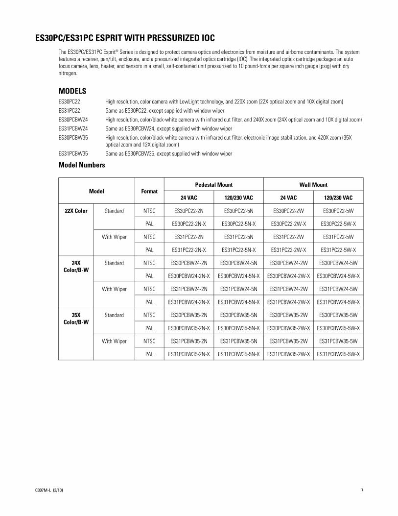
ES30PC/ES31PC ESPRIT WITH PRESSURIZED IOCThe ES30PC/ES31PC Esprit® Series is designed to protect camera optics and electronics from moisture and airborne contaminants. The system features a receiver, pan/tilt, enclosure, and a pressurized integrated optics cartridge (IOC). The integrated optics cartridge packages an auto focus camera, lens, heater, and sensors in a small, self-contained unit pressurized to 10 pound-force per square inch gauge (psig) with dry nitrogen.
MODELSES30PC22 High resolution, color camera with LowLight technology, and 220X zoom (22X optical zoom and 10X digital zoom)
ES31PC22 Same as ES30PC22, except supplied with window wiper
ES30PCBW24 High resolution, color/black-white camera with infrared cut filter, and 240X zoom (24X optical zoom and 10X digital zoom)
ES31PCBW24 Same as ES30PCBW24, except supplied with window wiper
ES30PCBW35 High resolution, color/black-white camera with infrared cut filter, electronic image stabilization, and 420X zoom (35X optical zoom and 12X digital zoom)
ES31PCBW35 Same as ES30PCBW35, except supplied with window wiper
Model Numbers
Model FormatPedestal Mount Wall Mount
24 VAC 120/230 VAC 24 VAC 120/230 VAC
22X Color Standard NTSC ES30PC22-2N ES30PC22-5N ES30PC22-2W ES30PC22-5W
PAL ES30PC22-2N-X ES30PC22-5N-X ES30PC22-2W-X ES30PC22-5W-X
With Wiper NTSC ES31PC22-2N ES31PC22-5N ES31PC22-2W ES31PC22-5W
PAL ES31PC22-2N-X ES31PC22-5N-X ES31PC22-2W-X ES31PC22-5W-X
24X Color/B-W
Standard NTSC ES30PCBW24-2N ES30PCBW24-5N ES30PCBW24-2W ES30PCBW24-5W
PAL ES30PCBW24-2N-X ES30PCBW24-5N-X ES30PCBW24-2W-X ES30PCBW24-5W-X
With Wiper NTSC ES31PCBW24-2N ES31PCBW24-5N ES31PCBW24-2W ES31PCBW24-5W
PAL ES31PCBW24-2N-X ES31PCBW24-5N-X ES31PCBW24-2W-X ES31PCBW24-5W-X
35X Color/B-W
Standard NTSC ES30PCBW35-2N ES30PCBW35-5N ES30PCBW35-2W ES30PCBW35-5W
PAL ES30PCBW35-2N-X ES30PCBW35-5N-X ES30PCBW35-2W-X ES30PCBW35-5W-X
With Wiper NTSC ES31PCBW35-2N ES31PCBW35-5N ES31PCBW35-2W ES31PCBW35-5W
PAL ES31PCBW35-2N-X ES31PCBW35-5N-X ES31PCBW35-2W-X ES31PCBW35-5W-X
C307M-L (3/10) 7

Installation1. When installing the ES30C/ES31C or ES30PC/ES31PC Esprit system, allow for sufficient clearance between the top of the unit and
overhead obstructions. This will prevent interference when the enclosure is driven to its maximum elevation of 33 degrees.
2. Remove the transformer module from the base of the system by loosening the four Phillips screws and lifting the module.
Figure 1. Removing the Transformer Module
3. Attach the base of the system to an Esprit mount (EWM or EPA):a. Apply a drop of Loctite® thread compound (supplied) to each of the three mounting holes and 10-32 x 1/2-inch flathead screws
(supplied).
WARNING: Applying the Loctite thread compound is an important step in the installation process. Failure to apply Loctite to the mounting holes may increase the risk of damage to the unit.
A33.0°
B
CD
Model ES30 ES31
A 16.6(42.5)
16.9(42.9)
B 9.4(23.9)
9.7(24.6)
C 7.1(18.1)
7.6(19.2)
D 4.2(10.7)
4.6(11.7)
NOTE: VALUES IN PARENTHESES ARE CENTIMETERS; ALL OTHERS ARE INCHES.
BASE
LOOSENPHILLIPSSCREWS
TRANSFORMERMODULE
8 C307M-L (3/10)

b. Attach the base of the system to the mount using the three screws and washers.
Figure 2. Attaching the Base to a Mount
4. Route the wires and cables through the center of the Esprit mount. Reinstall the transformer module into the base. The transformer module can be positioned in the mount base in only one orientation.
Figure 3. Reinstalling the Transformer Module
5. Models with 120/230 VAC only: Set the 120/230 voltage selector switch on the transformer to the appropriate voltage.
6. Connect wires and cables.a. Connect to power. Use the two supplied clamp connectors to connect the AC line and neutral.
b. Connect the video coaxial cable to the BNC connector.
c. Connect the wiring for a two-wire or four-wire control system. This step does not apply to Coaxitron® control systems.
120/230 VAC 24 VAC
Black wire Input (AC Line) White wire Input (AC Line)
White wire AC Neutral White wire AC Neutral
Green wire Ground Green wire Ground
Green wire RX–
Red wire RX+
Black wire TX–
White wire TX+
MOUNT
MOUNTING HOLES
BASE
MOUNTINGSCREWS
120/230 VOLTAGE SELECTOR SWITCH
C307M-L (3/10) 9

d. Connect AUX 2 (optional).
Figure 4. Wiring AUX 2
7. Install mount; refer to the installation manual supplied with the mount for instructions.
8. Turn on the power. If the red LED lights, turn off the power and proceed to the next step. If the red LED does not light, refer to Troubleshooting on page 72.
9. Plug the male Esprit system connector, located on the bottom of the pan/tilt, into the female Esprit system connector located on the transformer module. Align the pan/tilt part number with the alignment label of the base, and then attach the pan/tilt to the base with three 1/4-20 nuts and washers (supplied).
Figure 5. Attaching the Pan/Tilt to the Base
Orange wire AUX 2
Blue wire AUX 2 COMMON
AUX 2
AUX 2 COM
AUX 2
AUX 2 COM
ESPRIT
NOTE: CURRENT MUST NOT EXCEED 40 mA.
ORANGE WIRE
BLUE WIRE
USER ACCESSORY
D1 1N4005
K1 OMRON G5V-1-DC12
V1 32 VDC
PART NUMBER
MALE SYSTEM CONNECTOR
ALIGNMENT LABEL
FEMALE SYSTEM CONNECTOR
10 C307M-L (3/10)

10. Set the receiver address and system baud rate by configuring DIP switches SW1 and SW2.
NOTE: Switch settings have no effect on Coaxitron control signals. The Esprit will sense and automatically select input from Coaxitron control signals in either standard or extended mode.
To set the DIP switches:
a. Remove the plug from the left cover of the pan/tilt. It is not necessary to remove the pan/tilt cover.
b. Set the baud rate (SW1) and receiver address (SW2). For switch settings refer to the labels located on the inside lid of the housing or Table A and Table B in the Appendix on page 74.
c. Replace the plug.
11. Refer to Operation on page 14 and ES30C22/ES31C22 Menu Tree on page 20 manual for instructions on how to use your ES30C/ES31C Series Esprit integrated positioning system.
C307M-L (3/10) 11

Optional TXB Series Translator Board InstallationPelco’s TXB Series translator boards allow controllers from other companies to communicate with the Esprit system.
To install a TXB Series board, remove the left cover of the pan/tilt. Once the cover is removed, refer to the manual supplied with the translator board to complete the installation.
HOW TO REMOVE THE PAN/TILT COVER1. Unscrew the Phillips screw located on the left cover of the pan/tilt.
2. Remove and set aside the cover.
Figure 6. Removing the Pan/Tilt Cover
HOW TO REINSTALL THE PAN/TILT COVERThe pan/tilt covers must be properly seated and have a tight seal (all the way around) when installed.
Figure 7. Properly Seating the Pan/Tilt Covers
To reinstall the pan/tilt cover, do the following:
1. Properly position the cover and slide it into place. The sides of the cover must fit under the front and back rain guards of the pan/tilt, and the top of the cover must seat against the lip of the top gasket.
2. Apply pressure and push down the top of the cover to align the fastener holes.
PHILLIPS SCREW
PLUG
THIS SIDE IS IMPROPERLY INSTALLED
THIS SIDE IS PROPERLY INSTALLED
NOT SEALED
GAP
12 C307M-L (3/10)

3. Insert the Phillips screw and tighten. Tighten until the screw will not turn.
Figure 8. Reinstalling the Pan/Tilt Cover
TOP GASKET
FRONTRAINGUARD
C307M-L (3/10) 13

Operation
POWER-UP DISPLAYWhen the system is powered up, the selected protocol, revision number, and other information is displayed on the monitor. For example, the screen might show the following information:
The information remains on the monitor until the system receives a command.
HOW TO OPERATE YOUR SYSTEM
*Optical zoom magnifies the image and the picture remains clear. Resolution is constant.†Digital zoom magnifies the image and the picture may appear pixelated. The larger the zoom limit, the greater the reduction in resolution.
PRESET 95: ACCESSING MAIN MENUYou can call up the main menu on your monitor by programming (setting or creating) preset 95 (28 if in 32-preset mode).
Programming preset 95 for Pelco’s controllers varies according to the type of controller you are using. Instructions for programming preset 95 are given below for various Pelco controllers.
CM6700/CM68001. Enter the number of the camera and press the CAM key.
2. Enter 95 and hold the PRESET key for two seconds.
3. In the Edit Preset menu, arrow to SET, and then press the ACK key. The main menu appears.
Operation How to Control
Pan and Tilt Move joystick left/right and up/down.
ScanningStop scanRandom scanFrame scanAuto scan
Call preset 96.Call preset 97.Call preset 98.Call preset 99.
Zoom Far
To zoom far, do the following:1.Press the Zoom Tele button or turn the joystick clockwise until zoom stops at the optical zoom* limit.2.Release the button or joystick.3.To continue zooming (digitally), immediately press the button or turn the joystick clockwise again until you have the picture you want or reach the digital zoom† limit.
Zoom Wide Press the Zoom Wide button or turn the joystick counterclockwise.
Presets Refer to the documentation supplied with the controller.
Patterns Refer to the documentation supplied with the controller.
ESPRIT 35X IOP X.XXCONFIGURE DONE
D Address 1P Address 2Comm 2400, N, 8, 1
CAMERA XXXX-XXXX
14 C307M-L (3/10)

KBD200A/KBD300A: DIRECT MODE ONLY1. Enter 95.
2. Hold the PRESET key (approximately 5 seconds) until the main menu appears on the screen.
CM95001. Enter the number of the camera and press the CAM key. The main menu appears.
2. Highlight SETUP in the main menu and press the SELECT key.
3. Highlight CAM in the Setup menu and press the SELECT key.
4. Highlight PRESET in the Camera menu and press the SELECT key.
5. Enter 95 and press the F1 key. The main menu appears.
CM9740/CM9760/CM9770/CM97801. Press the ESCAPE key to open the main menu, and then select DEF. The Define Menu appears.
2. Enter your four-digit PIN if this is your first time entering this mode.
3. Enter 95 and select PRST. The main menu appears.
4. Select the Quit icon to return to the default menu.
KBD4000/KBD4002/KBD4000V1. Press the SPOT MONITOR key.
2. Enter 95, and then hold the PRESET key (approximately five seconds) until the main menu appears on the screen.
MPT9500
Standard Coaxitron® Mode1. Enter 95 and press the PRESET SET key.
2. Position the asterisk in the YES row and press the F1 key. The main menu appears.
Extended Coaxitron or RS-485 Mode1. Enter 95 and press the PRESET SET key.
2. Press the F2 key. The main menu appears.
ENDURA SYSTEMSIf your Esprit positioning system is connected to an Endura® system, you can access the main menu directly from the Endura workstation or the VCD5000. Note that access to the main menu is controlled through user permissions.
Endura Workstation1. Right-click in the video pane that is displaying video from an Esprit positioning system.
2. Click Preset, and then click Select Preset.
3. Enter 95, and the click OK.
VCD50001. Select a video pane that is displaying video from an Esprit positioning system.
2. Enter 95 on the KBD5000 keyboard. A shortcuts menu appears.
3. Press the Preset button on the keyboard.
C307M-L (3/10) 15

OPERATING NOTES
ENVIRONMENTAL RANGEThe operating temperature ranges from a minimum of -50°F (-45°C) to a maximum of 122°F (50°C) for sustained system operation or 140°F (60°C) absolute maximum. The entire unit can de-ice and be operational in two hours from a temperature of -13°F (-25°C). The thermostatically controlled heater consumes 10 W and cycles on at 70°F (21°C) and off at 85°F (29°C), while the window defroster runs continuously and consumes 2.5 W.
PAN/TILT FUNCTIONS
*50 mph wind-speed profile.†If manual limit stops are set, “Pan Limit” appears on your monitor when a limit stop is reached (except when you are programming or running a pattern). This does not apply to scan limit stops.
‡When the system reaches the upper limit, “Tilt Limit” appears on your monitor (except when you are programming or running a pattern).
If the proportional pan mode is enabled (refer to Proportional Pan on page 55), the pan/tilt speeds will depend on the amount of zoom. At telephoto zoom settings, the pan/tilt speeds will be slower for a given amount of joystick deflection than at wide zoom settings. This keeps the image from moving too fast on the monitor when there is a large amount of zoom. This slowing does not happen when going to a preset but does occur in Turbo mode when high zoom is selected. The minimum pan/tilt speeds are 0.1 degree per second at full zoom.
SCAN SPEEDScan speed is adjustable from 1 to 40 degrees per second through the programming menu.
PRESET FUNCTIONSThe Esprit system is capable of going to 80 preset locations, each with a 20-character label. The presets are numbered 1 to 32 and 35 to 82. Refer to the documentation for your control system for programming presets.
If you command the pan/tilt to go to an undefined preset, erratic operation may result.
Presets 33 and 34 are fixed commands, meaning that you cannot program them. Preset 33 is the “flip” command, which will pan the system 180 degrees. Preset 34 is the “pan zero” command, which will pan the system to the factory-determined zero reference point.
RANDOM, FRAME, AND AUTO SCANNINGSelect preset 97 (30) to start random scanning. Select preset 98 (31) to activate frame scanning (three seconds of scanning followed by a three-second pause). Select preset 99 (32) to start auto (continuous) scanning. Scan limit stops are controlled by software. Refer to Limit Stops on page 45 to program the scan limit stops.
When the pan/tilt reaches a scan limit stop, it reverses direction. Select preset 96 (29) to stop a scan. Any pan/tilt or lens command also will stop a scan.
ZONESA zone is a programmed pan area with set boundaries and identifying label. The Esprit system has a maximum of eight zones, each with a 20-character label. Zones can be programmed to blank video when the camera pans into the zone area. If a zone is blanked, the system displays the message, VIDEO BLANK. (Refer to Zone Blank on page 68 for instructions.)
ControllerType
Pan(Capability: 360° Continuous Pan Rotation)†
Tilt(Viewing Range: +33° to -83°)‡
Fixed speed Speed determined by controller Speed determined by controller
*Variable speed
*Turbo Mode*Preset Mode
0.1 to 40° per second, depending on joystick and zoom positions100° per second100° per second
0.1 to 20° per second, depending on joystick and zoom positionsDoes not affect the tilt speed30° per second
16 C307M-L (3/10)

PATTERNSThe Esprit system can do either one full pattern (1.5, 3, or 6 minutes long) or two half patterns (.75, 1.5, or 3 minutes long). This pattern can consist of any standard pan/tilt or lens command. Presets, flip, digital zoom, proportional pan, and Turbo are not allowed in a pattern. Zones can be enabled while running a pattern. Refer to the documentation for your control system to program and run patterns.
PARKIf the system does not receive any commands for a specified period of time (refer to Park Time Minutes on page 51), the system goes to preset 1 and parks. If the time specified is zero, or if preset 1 has not been programmed, the pan/tilt will not park.
IR FILTER(Applies only to 24X and 35X models.)
The 24X and 35X models have an IR (infrared) lens filter that can switch in and out, automatically or manually, depending on how the system is programmed. When the filter is IN, the camera produces a color picture. When the IR filter switches OUT, the picture changes to black-white, increasing visibility in low light conditions.
The Auto IR Level setting controls automatic operation of the filter. To manually override automatic operation, use presets 88 (filter IN) and 89 (filter OUT). The unit will remain in manual control until it is panned or tilted more than 15 degrees.
NOTE: Low light does not mean no light. Some type of illumination is required (street light, IR light, and so forth).
AUTO IRISIf auto iris is in the auto mode, it remains that way until you manually open or close the iris. The system will return to auto iris when it is panned or tilted more than 15 degrees.
WIPERThe ES31C Series features a window wiper to clear moisture from the enclosure glass. There are two modes of operation for the wiper, momentary and continuous. The wiper mode is easily set up through on-screen programming (refer to Wiper on page 67).
To operate the wiper do the following:
Momentary mode: To operate the wiper one full cycle, press the AUX 1 button on your controller. Each press of the button operates the wiper one full cycle, even if the AUX 1 button is latching. If AUX 1 is latching, the first press will activate the wiper (open the latch). Pressing AUX 1 a second time closes the latch, but will not cycle the wiper. Press the AUX 1 key again to cycle the wiper.
Continuous mode: To operate the wiper press the AUX 1 button on your controller. The wiper will continue to operate until the AUX 1 button is pressed again or until the programmed cycle is completed.
NOTE: (CM9740 and CM9760 matrix systems only) For the wiper to operate in continuous mode, the AUX 1 function in the camera file must be set to latching. If the AUX 1 camera file is not latching, the wiper will only operate in momentary mode, even if the Esprit wiper is programmed for continuous operation. Refer to the operation manual supplied with the CM9740 or CM9760 matrix system for instructions.
OPEN COLLECTOR AUXILIARY OUTPUTAn AUX 2 command from the controller will activate a device, such as a relay. The output will remain active for two seconds and then deactivate, even if the controller is set to latching mode.
Examples of devices that can be used with AUX 2 are a washer assembly (not supplied by Pelco) or a latching relay (not supplied by Pelco) attached to control a gate, lights, and so forth.
If a relay is used it must require less than 32 VDC and 40 mA to trigger the relay coil. The relay must be placed within 100 feet (30 m) of the Esprit unit.
C307M-L (3/10) 17

OPERATING NOTES: PRESSURIZED MODELS ONLY
PRESSURIZED INTEGRATED OPTICS CARTRIDGEThe pressurized IOC houses an auto focus camera, lens, heater, and sensors in a self-contained, sealed unit. Dry nitrogen pressurized to 10 psig controls the environment inside the cartridge, eliminating internal condensation and corrosion.
Sensors strategically placed inside the pressurized IOC continually monitor pressure, temperature, and relative humidity. If internal conditions reach unacceptable levels, an alert label appears on the screen describing the alert condition. Example: If pressure drops below 1 psig, Low Pressure is displayed on the monitor.
The following conditions will trigger an alert:
ALERT LABEL CYCLEThe Esprit system continually checks internal environmental conditions every 60 seconds. An Alert label appears on the monitor if conditions are beyond manufacturer set acceptable limits. The label will be repeatedly displayed until acknowledged by the system controller. Once acknowledged, alert behavior changes to the programmed acknowledge action. If the alert condition remains unacceptable after a period of time, the Alert label will reappear on the monitor, restarting the alert label cycle. The cycle will continue until the alert condition is resolved.
Condition Alert Label
1 psig Low Pressure
25 psig High Pressure
-40°C Low Temperature
60°C High Temperature
20% High Relative Humidity
USER DEFINED REFER TO REPEAT IN THE PROGRAMMING SECTION OF THIS MANUAL
USER DEFINED REFER TO ACK ACT IN THE PROGRAMMING SECTION OF THIS MANUAL
ALERT LABELDISPLAYED ON
MONITOR
REPEATALERT LABEL IS
DISPLAYED ON MONITOR UNTIL ACKNOWLEDGED
BY CONTROLLER
ACK ALERTALERT ACKNOWLEDGED
CYCL
E RE
PEAT
S UN
TIL
CON
DITI
ON IS
RES
OLVE
D
ALERT CONDITIONNOT RESOLVED
ACK ACTONCE ACKNOWLEDGED ALERT LABEL BEHAVIOR
CHANGES TO THE ACTIVE RESPONSE PROGRAMMED
FOR ACK ACT
ALERT CONDITIONLABEL OFF
RESOLVED
18 C307M-L (3/10)

C307M-L (3/10) 19
ALERT RESETThe Alert Reset function clears alert conditions and removes the Alert label. The system will automatically check internal environmental conditions 60 seconds after reset. If conditions remain beyond manufacturer set acceptable limits, the Alert label will reappear on the screen indicating further corrective action is required.
CURRENT READING MENU
The Current Reading menu displays the existing status of temperature, pressure, and dewpoint inside the integrated optics cartridge. An asterisk displayed to the left of a menu item denotes that an alert condition exists.
Due to the heat emitted from the electronics of the camera, normal temperature operating range is approximately 95°F.
Temperature 37 C 98 FDewpoint 08 C 46 FPressure 10.30 psig 0.71 bar
RefreshExit
IOC Internal Reading
20 C307M-L (3/10)
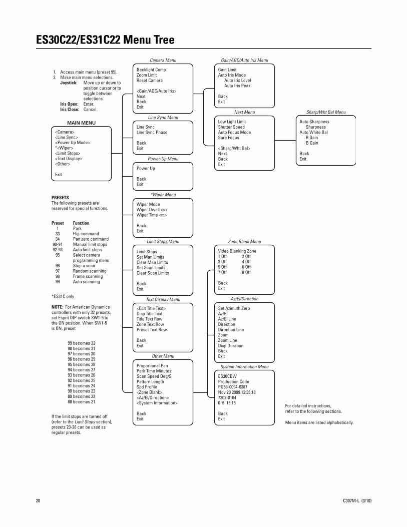
ES30C22/ES31C22 Menu Tree
For detailed instructions,refer to the following sections.
Menu items are listed alphabetically.
ES30CBWProduction CodePG53-0094-0387Nov 20 2009 13:35:187202-01040 6 15:15
BackExit
System Information Menu
Set Azimuth ZeroAz/ElAz/El LineDirectionDirection LineZoomZoom LineDisp DurationBackExit
Az/El/Direction
Video Blanking Zone1 Off 2 Off3 Off 4 Off5 Off 6 Off7 Off 8 Off
BackExit
Zone Blank Menu
Auto Sharpness SharpnessAuto White Bal R Gain B Gain
BackExit
Sharp/Wht Bal Menu
Low Light LimitShutter SpeedAuto Focus ModeSure Focus
<Sharp/Wht Bal>NextBackExit
Next Menu
Gain LimitAuto Iris Mode Auto Iris Level Auto Iris Peak
BackExit
Gain/AGC/Auto Iris Menu
Proportional PanPark Time MinutesScan Speed Deg/SPattern LengthSpd Profile<Zone Blank><Az/El/Direction><System Information>
BackExit
Other Menu
<Edit Title Text>Disp Title TextTitle Text RowZone Text RowPreset Text Row
BackExit
Text Display Menu
Limit StopsSet Man LimitsClear Man LimitsSet Scan LimitsClear Scan Limits
BackExit
Limit Stops Menu
Wiper ModeWiper Dwell <s>Wiper Time <m>
BackExit
*Wiper Menu
Power Up
BackExit
Power-Up Menu
Line SyncLine Sync Phase
BackExit
Line Sync Menu
Backlight CompZoom LimitReset Camera
<Gain/AGC/Auto Iris>NextBackExit
Camera Menu
If the limit stops are turned off(refer to the Limit Stops section),presets 23-26 can be used asregular presets.
99 becomes 3298 becomes 3197 becomes 3096 becomes 2995 becomes 2894 becomes 2793 becomes 2692 becomes 2591 becomes 2490 becomes 2389 becomes 2288 becomes 21
*ES31C only
NOTE: For American Dynamicscontrollers with only 32 presets,set Esprit DIP switch SW1-5 tothe ON position. When SW1-5is ON, preset
FunctionParkFlip commandPan zero commandManual limit stopsAuto limit stopsSelect cameraprogramming menuStop a scanRandom scanningFrame scanningAuto scanning
Preset1
3334
90-9192-93
95
96979899
PRESETSThe following presets arereserved for special functions.
<Camera><Line Sync><Power Up Mode>*<Wiper><Limit Stops><Text Display><Other>
Exit
MAIN MENU
1. Access main menu (preset 95).2. Make main menu selections. Joystick: Move up or down to position cursor or to toggle between selections. Iris Open: Enter. Iris Close: Cancel.

ES30CBW24/ES31CBW24 Menu Tree
For detailed instructions,refer to the following sections.
Menu items are listed alphabetically.
IR Filt/Sharp/Wht Bal Menu
Auto Sharpness SharpnessAuto White Bal R Gain B GainIR Filter Mode Auto IR Level
BackExit
System Information Menu
ES30CBWProduction CodePG53-0094-0387Nov 20 2009 13:35:187202-01040 6 15:15
BackExit
Az/El/Direction
Set Azimuth ZeroAz/ElAz/El LineDirectionDirection LineZoomZoom LineDisp DurationBackExit
Zone Blank Menu
Video Blanking Zone1 Off 2 Off3 Off 4 Off5 Off 6 Off7 Off 8 Off
BackExit
Next Menu
Low Light LimitShutter SpeedAuto Focus ModeSure FocusLowLight Focus<IR Filt/Sharp/Wht Bal>
BackExit
AGC/Auto Iris/ToL Menu
Gain LimitAuto Iris Mode Auto Iris Level Auto Iris Peak
BackExit
Other Menu
Proportional PanPark Time MinutesScan Speed Deg/SPattern LengthSpd Profile<Zone Blank><Az/El/Direction><System Information>
BackExit
Text Display Menu
<Edit Title Text>Disp Title TextTitle Text RowZone Text RowPreset Text Row
BackExit
Limit Stops Menu
Limit StopsSet Man LimitsClear Man LimitsSet Scan LimitsClear Scan Limits
BackExit
*Wiper Menu
Wiper ModeWiper Dwell <s>Wiper Time <m>
BackExit
Power Up
BackExit
Power-Up Menu
Line Sync Menu
Line SyncLine Sync Phase
BackExit
Camera Menu
Backlight CompZoom LimitReset CameraWDRField Alignment
<AGC/Auto Iris/ToL>NextBackExit
If the limit stops are turned off(refer to the Limit Stops section),presets 23-26 can be used asregular presets.
99 becomes 3298 becomes 3197 becomes 3096 becomes 2995 becomes 2894 becomes 2793 becomes 2692 becomes 2591 becomes 2490 becomes 2389 becomes 2288 becomes 21
NOTE: For American Dynamicscontrollers with only 32 presets,set Esprit DIP switch SW1-5 tothe ON position. When SW1-5is ON, preset
*ES31C only
FunctionParkFlip commandPan zero commandIR filter INIR filter OUTManual limit stopsAuto limit stopsSelect cameraprogramming menuStop a scanRandom scanningFrame scanningAuto scanning
Preset1
33348889
90-9192-93
95
96979899
PRESETSThe following presets arereserved for special functions.
<Camera><Line Sync><Power Up Mode>*<Wiper><Limit Stops><Text Display><Other>
Exit
MAIN MENU
1. Access main menu (preset 95).2. Make main menu selections.
Joystick: Move up or down to position cursor or to toggle between selections.Iris Open: Enter.Iris Close: Cancel.
C307M-L (3/10) 21

ES30CBW35/ES31CBW35 Menu Tree
For detailed instructions,refer to the following sections.
Menu items are listed alphabetically.
ES31CBW35aProduction CodePG53-0094-0400Nov 20 2009 13:35:187202-01040 6 15:15
BackExit
System Information Menu
Set Azimuth ZeroAz/ElAz/El LineDirectionDirection LineZoomZoom LineDisp DurationBackExit
Az/El/Direction
Video Blanking Zone1 Off 2 Off3 Off 4 Off5 Off 6 Off7 Off 8 Off
BackExit
Zone Blank Menu
Picture ModeLow Lux NR
BackExit
Next Menu
Auto Sharpness SharpnessAuto White Bal R Gain B GainIR Filter Mode Auto IR Level
BackExit
IR Filt/Sharp/Wht Bal Menu
Low Light LimitShutter SpeedAuto Focus ModeSure FocusLow Light FocusImg Stabilizer<IR Filt/Sharp/Wht Bal>
NextBackExit
Next Menu
Gain LimitAuto Iris Mode Auto Iris Level Auto Iris PeakType of Lighting
BackExit
AGC/Auto Iris/ToL Menu
Proportional PanPark Time MinutesScan Speed deg/sPattern LengthSpd Profile<Zone Blank><Az/El/Direction><System Information>
BackExit
Other Menu
<Edit Title Text>Disp Title TextTitle Text RowZone Text RowPreset Text Row
BackExit
Text Display Menu
Limit StopsSet Man LimitsClear Man LimitsSet Scan LimitsClear Scan Limits
BackExit
Limit Stops Menu
Wiper ModeWiper Dwell <s>Wiper Time <m>
BackExit
*Wiper Menu
Power Up
BackExit
Power-Up Menu
Line SyncLine Sync Phase
BackExit
Line Sync Menu
Backlight CompZoom LimitReset CameraWDRField Alignment
<AGC/Auto Iris/ToL>NextBackExit
Camera Menu
If the limit stops are turned off(refer to the Limit Stops section),presets 23-26 can be used asregular presets.
99 becomes 3298 becomes 3197 becomes 3096 becomes 2995 becomes 2894 becomes 2793 becomes 2692 becomes 2591 becomes 2490 becomes 2389 becomes 2288 becomes 21
*ES31C only
NOTE: For American Dynamicscontrollers with only 32 presets,set Esprit DIP switch SW1-5 tothe ON position. When SW1-5is ON, preset
FunctionParkFlip commandPan zero commandIR filter INIR filter OUTManual limit stopsAuto limit stopsSelect cameraprogramming menuStop a scanRandom scanningFrame scanningAuto scanning
Preset133348889
90-9192-93
95
96979899
PRESETSThe following presets arereserved for special functions.
<Camera><Line Sync><Power Up Mode>*<Wiper><Limit Stops><Text Display><Other>
Exit
MAIN MENU
1. Access main menu (preset 95).2. Make main menu selections. Joystick: Move up or down to position cursor or to toggle between selections. Iris Open: Enter. Iris Close: Cancel.
22 C307M-L (3/10)

ES30PC22/ES31PC22 Menu Tree
For detailed instructions,refer to the following sections.
Menu items are listed alphabetically.
System Information Menu
ES30CBWProduction CodePG53-0094-0387Nov 20 2009 13:35:187202-01040 6 15:15
BackExit
Az/El/Direction
Set Azimuth ZeroAz/ElAz/El LineDirectionDirection LineZoomZoom LineDisp DurationBackExit
Zone Blank Menu
Video Blanking Zone1 Off 2 Off3 Off 4 Off5 Off 6 Off7 Off 8 Off
BackExit
Sharp/Wht Bal Menu
Auto Sharpness SharpnessAuto White Bal R Gain B Gain
BackExit
RepeatAlert Disp RowDisp PosACK Act<Current Reading>Alert ResetBackExit
Alert Menu
37C98F06C46F
10.30 psig0.71 bsr
Temperature
Dewpoint
Pressure
RefreshBackExit
IOC Intermal Reading
Low Light LimitShutter SpeedAuto Focus ModeSure Focus
<Sharp/Wht Bal>NextBackExit
Next Menu
Gain/AGC/Auto Iris Menu
Gain LimitAuto Iris Mode Auto Iris Level Auto Iris Peak
NextBackExit
Proportional PanPark Time MinutesScan Speed Deg/SPattern LengthSpd Profile<Zone Blank><Az/El/Direction><System Information>BackExit
Other Menu
<Edit Title Text>Disp Title TextTitle Text RowZone Text RowPreset Text Row
BackExit
Text Display Menu
Limit StopsSet Man LimitsClear Man LimitsSet Scan LimitsClear Scan Limits
BackExit
Limit Stops Menu
Wiper ModeWiper Dwell <s>Wiper Time <m>
BackExit
*Wiper Menu
Power Up
BackExit
Power-Up Menu
Line SyncLine Sync Phase
BackExit
Line Sync Menu
Backlight CompZoom LimitReset Camera
<Gain/AGC/Auto Iris>NextBackExit
Camera Menu
If the limit stops are turned off(refer to the Limit Stops section),presets 23-26 can be used asregular presets.
99 becomes 3298 becomes 3197 becomes 3096 becomes 2995 becomes 2894 becomes 2793 becomes 2692 becomes 2591 becomes 2490 becomes 2389 becomes 2288 becomes 21
*ES31C only
NOTE: For American Dynamicscontrollers with only 32 presets,set Esprit DIP switch SW1-5 tothe ON position. When SW1-5is ON, preset
FunctionParkFlip commandPan zero commandManual limit stopsAuto limit stopsSelect cameraprogramming menuStop a scanRandom scanningFrame scanningAuto scanning
Preset1
3334
90-9192-93
95
96979899
PRESETSThe following presets arereserved for special functions.
MAIN MENU
<Camera><Line Sync><Power Up Mode>*<Wiper><Limit Stops><Text Display><Alert><Other>Exit
1. Access main menu (preset 95).2. Make main menu selections. Joystick: Move up or down to position cursor or to toggle between selections. Iris Open: Enter. Iris Close: Cancel.
C307M-L (3/10) 23

24 C307M-L (3/10)
ES30PCBW24/ES31PCBW24 Menu Tree
For detailed instructions,refer to the following sections.
Menu items are listed alphabetically.
ES30CBWProduction CodePG53-0094-0387Nov 20 2009 13:35:187202-01040 6 15:15
BackExit
System Information Menu
Set Azimuth ZeroAz/ElAz/El LineDirectionDirection LineZoomZoom LineDisp Duration
BackExit
Az/El/Direction
Video Blanking Zone1 Off 2 Off3 Off 4 Off5 Off 6 Off7 Off 8 Off
BackExit
Zone Blank Menu
Auto Sharpness SharpnessAuto White Bal R Gain B GainIR Filter Mode Auto IR Level
BackExit
IR Filt/Sharp/Wht Bal Menu
RepeatAlert Disp RowDisp PosACK Act<Current Reading>Alert Reset
BackExit
Alert Menu
Low Light LimitShutter SpeedAuto Focus ModeSure FocusLowLight Focus
<IR Filt/Sharp/Wht Bal>
BackExit
Next Menu
Gain LimitAuto Iris Mode Auto Iris Level Auto Iris Peak
BackExit
AGC/Auto Iris/ToL Menu
Proportional PanPark Time MinutesScan Speed Deg/SPattern LengthSpd Profile<Zone Blank><Az/El/Direction><System Information>
BackExit
Other Menu
37C98F06C46F
10.30 psig0.71 bsr
Temperature
Dewpoint
Pressure
Refresh
BackExit
IOC Intermal Reading
<Edit Title Text>Disp Title TextTitle Text RowZone Text RowPreset Text Row
BackExit
Text Display Menu
Limit StopsSet Man LimitsClear Man LimitsSet Scan LimitsClear Scan Limits
BackExit
Limit Stops Menu
Wiper ModeWiper Dwell <s>Wiper Time <m>
BackExit
*Wiper Menu
Power Up
BackExit
Power-Up Menu
Line SyncLine Sync Phase
BackExit
Line Sync Menu
Backlight CompZoom LimitReset CameraWDRField Alignment<AGC/Auto Iris/ToL>NextBackExit
Camera Menu
If the limit stops are turned off(refer to the Limit Stops section),presets 23-26 can be used asregular presets.
99 becomes 3298 becomes 3197 becomes 3096 becomes 2995 becomes 2894 becomes 2793 becomes 2692 becomes 2591 becomes 2490 becomes 2389 becomes 2288 becomes 21
*ES31C only
NOTE: For American Dynamicscontrollers with only 32 presets,set Esprit DIP switch SW1-5 tothe ON position. When SW1-5is ON, preset
FunctionParkFlip commandPan zero commandIR filter INIR filter OUTManual limit stopsAuto limit stopsSelect cameraprogramming menuStop a scanRandom scanningFrame scanningAuto scanning
Preset1
33348889
90-9192-93
95
96979899
PRESETSThe following presets arereserved for special functions.
<Camera><Line Sync><Power Up Mode>*<Wiper><Limit Stops><Text Display><Alert><Other>Exit
MAIN MENU
1. Access main menu (preset 95).2. Make main menu selections. Joystick: Move up or down to position cursor or to toggle between selections. Iris Open: Enter. Iris Close: Cancel.

C307M-L (3/10) 25
ES30PCBW35/ES31PCBW35 Menu Tree
For detailed instructions,refer to the following sections.
Menu items are listed alphabetically.
ES31PCBW35aProduction CodePG53-0094-0400Nov 20 2009 13:35:187202-01040 6 15:15
BackExit
System Information Menu
Set Azimuth ZeroAz/ElAz/El LineDirectionDirection LineZoomZoom LineDisp DurationBackExit
Az/El/Direction
Video Blanking Zone1 Off 2 Off3 Off 4 Off5 Off 6 Off7 Off 8 Off
BackExit
Zone Blank Menu
Picture ModeLow Lux NR
BackExit
Next Menu
Auto Sharpness SharpnessAuto White Bal R Gain B GainIR Filter Mode Auto IR Level
BackExit
IR Filt/Sharp/Wht Bal Menu
RepeatAlert Disp RowDisp PosACK Act<Current Reading>Alert ResetBackExit
Alert Menu
Low Light LimitShutter SpeedAuto Focus ModeSure FocusLowLight FocusImg Stabilizer<IR Filt/Sharp/Wht Bal>NextBackExit
Next Menu
Gain LimitAuto Iris Mode Auto Iris Level Auto Iris PeakType of Lighting
BackExit
AGC/Auto Iris/ToL Menu
Proportional PanPark Time MinutesScan Speed Deg/SPattern LengthSpd Profile<Zone Blank><Az/El/Direction><System Information>BackExit
Other Menu
37C98F06C46F
10.30 psig0.71 bsr
Temperature
Dewpoint
Pressure
RefreshBackExit
IOC Intermal Reading
<Edit Title Text>Disp Title TextTitle Text RowZone Text RowPreset Text RowBackExit
Text Display Menu
Limit StopsSet Man LimitsClear Man LimitsSet Scan LimitsClear Scan Limits
BackExit
Limit Stops Menu
Wiper ModeWiper Dwell <s>Wiper Time <m>
BackExit
*Wiper Menu
Power Up
BackExit
Power-Up Menu
Line SyncLine Sync Phase
BackExit
Line Sync Menu
Backlight CompZoom LimitReset CameraWDRField Alignment
<AGC/Auto Iris/ToL>NextBackExit
Camera Menu
If the limit stops are turned off(refer to the Limit Stops section)presets 23-26 can be used asregular presets.
99 becomes 3298 becomes 3197 becomes 3096 becomes 2995 becomes 2894 becomes 2793 becomes 2692 becomes 2591 becomes 2490 becomes 2389 becomes 2288 becomes 21
*ES31C only
NOTE: For American Dynamicscontrollers with only 32 presets,set Esprit DIP switch SW1-5 tothe ON position. When SW1-5is ON, preset
FunctionParkFlip commandPan zero commandIR filter INIR filter OUTManual limit stopsAuto limit stopsSelect cameraprogramming menuStop a scanRandom scanningFrame scanningAuto scanning
Preset1
33348889
90-9192-93
95
96979899
PRESETSThe following presets arereserved for special functions.
<Camera><Line Sync><Power Up Mode>*<Wiper><Limit Stops><Text Display><Alert><Other>Exit
MAIN MENU
1. Access main menu (preset 95).2. Make main menu selections. Joystick: Move up or down to position cursor or to toggle between selections. Iris Open: Enter. Iris Close: Cancel.

Configuration
ACK ACT(Applies only to pressurized models.)
If an envirornmental condition inside of the IOC goes outside of the factory set limits (such as Low Pressure) then select ACK Alert to activate the alert label behavior. Program ACK Act (acknowledge action) to establish alert label behavior after alert acknowledgement. The following acknowledge actions are available:
• Always on: The alert label is displayed until alert conditions are clear.
• Off 8 hrs: The alert label is turned off for 8 hours. Label returns after 8 hours if the alert condition persists.
• Off 24 hrs: The alert label is turned off for 24 hours. Label returns after 24 hours if the alert condition persists.
• Off 48 hrs: The alert label is turned off for 48 hours. Label returns after 48 hours if the alert condition persists.
To set the acknowledge action:
1. Program preset 95 (28). The main menu appears.
2. Position the cursor (>) beside Alert.
3. Press the Iris Open button to enter the Alert menu.
4. Position the cursor (>) beside ACK Act.
5. Press the Iris Open button. The cursor moves to the right.
6. Move the joystick up or down to make a selection.
7. Press one of the following buttons on your keyboard:
• Iris Open: Press the Iris Open button to select your choice.• Iris Close: Press the Iris Close button if you do not want to change the setting.
MAIN MENU<Camera><Line Sync><Power Up Mode><Wiper><Limit Stops><Text Display><Alert><Other>ACK AlertExit
Repeat ConstantAlert Disp RowDisp Pos RightACK Act Always On<Currrent Reading>Alert ResetBackExit
Alert Menu
26 C307M-L (3/10)

ALERT DISPLAY POSITION(Applies only to pressurized models.)
Screen positioning of the alert label is user-defined. Positioning options include Center, Left, and Right.
To set the alert label position:
1. Program preset 95 (28). The main menu appears.
2. Position the cursor (>) beside Alert.
3. Press the Iris Open button to enter the Alert menu.
4. Position the cursor (>) beside Disp Pos.
5. Press the Iris Open button. The cursor moves to the right.
6. Move the joystick up or down to make a selection.
7. Press one of the following buttons on your keyboard:
• Iris Open: Press the Iris Open button to select your choice.• Iris Close: Press the Iris Close button if you do not want to change the setting.
MAIN MENU<Camera><Line Sync><Power Up Mode><Wiper><Limit Stops><Text Display><Alert><Other>ACK AlertExit
Repeat ConstantAlert Disp RowDisp Pos RightACK Act Always On<Currrent Reading>Alert ResetBackExit
Alert Menu
C307M-L (3/10) 27

ALERT DISPLAY ROW(Applies only to pressurized models.)
The row on which the alert label is displayed is user-defined. Display row options include rows 1 through 12.
To set the alert display row:
1. Program preset 95 (28). The main menu appears.
2. Position the cursor (>) beside Alert.
3. Press the Iris Open button to enter the Alert menu.
4. Position the cursor (>) beside Alert Disp Row.
5. Press the Iris Open button. The cursor moves to the right.
6. Move the joystick up or down to make a selection.
7. Press one of the following buttons on your keyboard:
• Iris Open: Press the Iris Open button to select your choice.• Iris Close: Press the Iris Close button if you do not want to change the setting.
MAIN MENU<Camera><Line Sync><Power Up Mode><Wiper><Limit Stops><Text Display><Alert><Other>ACK AlertExit
Repeat ConstantAlert Disp RowDisp Pos RightACK Act Always On<Currrent Reading>Alert ResetBackExit
Alert Menu
28 C307M-L (3/10)

ALERT REPEAT(Applies only to pressurized models.)
You can program how often an ALERT label is repeatedly displayed until it is acknowledged by the system controller. The following settings are available:
• Constant: The ALERT label is continually displayed on the monitor until acknowledged.
• 15 min off: The ALERT label is displayed every 15 minutes for a 15-second duration until acknowledged.
• 30 min off: The ALERT label is displayed every 30 minutes for a 15-second duration until acknowledged.
• 60 min off: The ALERT label is displayed every 60 minutes for a 15-second duration until acknowledged.
To program the alert repeat setting:
1. Program preset 95 (28). The main menu appears.
2. Position the cursor (>) beside Alert.
3. Press the Iris Open button to enter the Alert menu.
4. Position the cursor (>) beside Repeat.
5. Press the Iris Open button. The cursor moves to the right.
6. Move the joystick up or down to select the repeat setting.
7. Press one of the following buttons on your keyboard:
• Iris Open: Press the Iris Open button to select your choice.• Iris Close: Press the Iris Close button if you do not want to change the setting.
MAIN MENU<Camera><Line Sync><Power Up Mode><Wiper><Limit Stops><Text Display><Alert><Other>ACK AlertExit
Repeat ConstantAlert Disp RowDisp Pos RightACK Act Always On<Currrent Reading>Alert ResetBackExit
Alert Menu
C307M-L (3/10) 29

AUTO FOCUS MODE
There are two auto focus modes:
• Auto: If auto focus is in the auto mode, pressing the Focus Far or Focus Near button will place the focus in the manual mode. The system will return to auto focus if you pan or tilt the unit or do a zoom function.
• Off: If the mode is set to Off, the system will operate in the manual mode.
NOTE: Auto focus does not operate at shutter speeds longer than 1/8 of a second.
To change the mode:
1. Program preset 95 (28). The main menu appears.
2. Position the cursor (>) beside Camera.
3. Press the Iris Open button to enter the Camera menu.
4. Position the cursor (>) beside Next.
5. Press the Iris Open button to go to the Next menu.
6. Position the cursor (>) beside Auto Focus Mode.
7. Press the Iris Open button. The cursor moves to the right, beside Auto or Off.
8. Move the joystick up or down to toggle between Auto and Off.
9. Press one of the following buttons on your keyboard:
• Iris Open: Press the Iris Open button to select your choice.
• Iris Close: Press the Iris Close button if you do not want to change the setting.
Backlight CompZoom LimitReset CameraWDRField Alignment
<AGC/Auto Iris/ToL>NextBackExit
Camera MenuMAIN MENU
<Camera><Line Sync><Power Up Mode><Wiper><Limit Stops><Text Display><Other>Exit
LowLight LimitShutter Speed
Auto Focus ModeSure Focus LowLight Focus Img Stabilizer <IR Filt/Sharp/Wht Bal>NextBackExit
Next Menu
30 C307M-L (3/10)
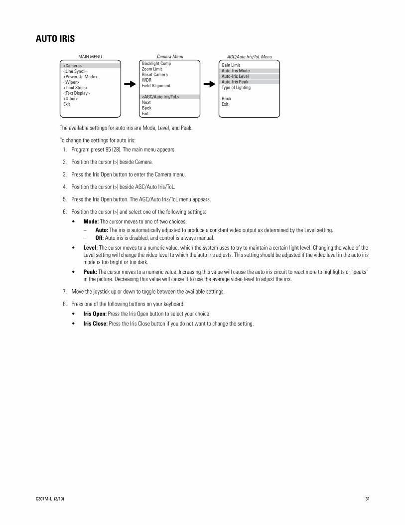
AUTO IRIS
The available settings for auto iris are Mode, Level, and Peak.
To change the settings for auto iris:
1. Program preset 95 (28). The main menu appears.
2. Position the cursor (>) beside Camera.
3. Press the Iris Open button to enter the Camera menu.
4. Position the cursor (>) beside AGC/Auto Iris/ToL.
5. Press the Iris Open button. The AGC/Auto Iris/ToL menu appears.
6. Position the cursor (>) and select one of the following settings:
• Mode: The cursor moves to one of two choices: – Auto: The iris is automatically adjusted to produce a constant video output as determined by the Level setting.– Off: Auto iris is disabled, and control is always manual.
• Level: The cursor moves to a numeric value, which the system uses to try to maintain a certain light level. Changing the value of the Level setting will change the video level to which the auto iris adjusts. This setting should be adjusted if the video level in the auto iris mode is too bright or too dark.
• Peak: The cursor moves to a numeric value. Increasing this value will cause the auto iris circuit to react more to highlights or “peaks” in the picture. Decreasing this value will cause it to use the average video level to adjust the iris.
7. Move the joystick up or down to toggle between the available settings.
8. Press one of the following buttons on your keyboard:
• Iris Open: Press the Iris Open button to select your choice.
• Iris Close: Press the Iris Close button if you do not want to change the setting.
Backlight CompZoom Limit
Reset CameraWDRField Alignment
<AGC/Auto Iris/ToL>NextBackExit
Camera Menu AGC/Auto Iris/ToL Menu
Gain LimitAuto-Iris ModeAuto-Iris LevelAuto-Iris PeakType of Lighting
BackExit
MAIN MENU
<Camera><Line Sync><Power Up Mode><Wiper><Limit Stops><Text Display><Other>Exit
C307M-L (3/10) 31

AUTO IR LEVEL(Applies only to 24X and 35X models.)
The auto IR level is the light level at which the infrared filter switches IN or OUT. The following are the available settings for the Auto IR Level:
• Dusk (default): Approximately 6 lux (black-white) approximately 13 lux (color)
• Dark: Approximately 0.1 lux (black-white) approximately 2 lux (color)
NOTES:
• If backlight compensation is ON and the IR cut filter switches OUT in normal lighting conditions, adjust the Auto IR Level to a darker setting. Refer to Backlight Compensation on page 37.
• Low light does not mean no light. Some type of illumination is required (street light, IR light, and so forth). The camera is not sensitive to IR light when the IR cut filter is IN.
To change the auto lR level settings:
1. Program preset 95 (28). The main menu appears.
2. Position the cursor (>) beside Camera.
3. Press the Iris Open button to enter the Camera menu.
4. Position the cursor (>) beside Next.
5. Press the Iris Open button to enter the Next menu.
6. Position the cursor (>) beside IR Filt/Sharp/Wht Bal.
7. Press the Iris Open button to enter the IR Filt/Sharp/Wht Bal menu.
8. Position the cursor (>) beside Auto IR Level.
9. Press the Iris Open button. The cursor moves to the right.
10. Move the joystick up or down to toggle between the level settings.
11. Press one of the following buttons on your keyboard:
• Iris Open: Press the Iris Open button to select your choice.
• Iris Close: Press the Iris Close button if you do not want to change the setting.
Backlight CompZoom LimitReset CameraWDRField Alignment
<AGC/Auto Iris/ToL>NextBackExit
Camera Menu
LowLight LimitShutter SpeedAuto Focus ModeSure FocusLowLight FocusImg Stabilizer<IR Filt/Sharp/Wht Bal>NextBackExit
Next Menu IR Filt/Sharp/Wht Bal Menu
Auto SharpnessSharpnessAuto White BalR GainB GainIR Filter ModeAuto IR Level
BackExit
MAIN MENU
<Camera><Line Sync><Power Up Mode><Wiper><Limit Stops><Text Display><Other>Exit
32 C307M-L (3/10)

AUTO SHARPNESS
The following settings are available for auto sharpness:
• On: Automatically sets the sharpness of the camera.
• Off: The sharpness of the camera needs to be manually set (refer to Sharpness).
To change the mode:
1. Program preset 95 (28). The main menu appears.
2. Position the cursor (>) beside Camera.
3. Press the Iris Open button to enter the Camera menu.
4. Position the cursor (>) beside Next.
5. Press the Iris Open button to enter the Next menu.
6. Position the cursor (>) beside IR Filt/Sharp/Wht Bal.
7. Press the Iris Open button to enter the IR Filt/Sharp/Wht Bal menu.
8. Position the cursor (>) beside Auto Sharpness.
9. Press the Iris Open button. The cursor moves to the right.
10. Move the joystick up or down to toggle between On and Off.
11. Press one of the following buttons on your keyboard:
• Iris Open: Press the Iris Open button to select your choice.
• Iris Close: Press the Iris Close button if you do not want to change the setting.
Backlight CompZoom LimitReset CameraWDRField Alignment
<AGC/Auto Iris/ToL>NextBackExit
Camera MenuLowLight LimitShutter SpeedAuto Focus ModeSure FocusLowLight FocusImg Stabilizer<IR Filt/Sharp/Wht Bal>NextBackExit
Next MenuAuto SharpnessSharpnessAuto White BalR GainB GainIR Filter ModeAuto IR Level
BackExit
IR Filt/Sharp/Wht Bal MenuMAIN MENU
<Camera><Line Sync><Power Up Mode><Wiper><Limit Stops><Text Display><Other>Exit
C307M-L (3/10) 33

AZ/EL
Az/El programs the horizontal display position of the Azimuth*/Elevation† label.
NOTE: Az/El display is not available while you are programming or running a pattern.
The following settings are available for the Az/El label:
• Off: Label is not displayed.
• Left (default): Label is displayed on the left-hand side of the screen.
• Center: Label is displayed in the center of the screen.
• Right: Label is displayed on the right-hand side of the screen.
To program the horizontal label position for Az/El:
1. Program preset 95 (28). The main menu appears.
2. Position the cursor (>) beside Other.
3. Press the Iris Open button to enter the Other menu.
4. Position the cursor (>) beside Az/El/Direction.
5. Press the Iris Open button to enter the Az/El/Direction menu.
6. Position the cursor (>) beside Az/El.
7. Press the Iris Open button. The cursor moves to the right.
8. Move the joystick up or down to view the available selections.
9. Press one of the following buttons on your keyboard:
• Iris Open: Press the Iris Open button to select your choice.
• Iris Close: Press the Iris Close button if you do not want to change the setting.
* Azimuth is the pan angle from zero to 359 degrees.† Elevation is the tilt position from 33 to -83 degrees.
Proportional Pan Park Time Minutes Scan Speed Deg/S Pattern Length Spd Profile<Zone Blank><Az/El/Direction><System Information>BackExit
Other Menu Az/El/DirectionSet Azimuth ZeroAz/ElAz/El LineDirectionDirection LineZoomZoom LineDisp DurationBackExit
MAIN MENU
<Camera><Line Sync><Power Up Mode><Wiper><Limit Stops><Text Display><Other>Exit
34 C307M-L (3/10)

AZ/EL LINE
Az/El Line controls the vertical display position of the Azimuth/Elevation label. The label may be displayed on lines 3 through 12. Line 3 is the third line from the top of the screen and line 12 is located at the bottom of the screen. Line 10 is the default setting.
NOTE: Az/El display is not available while you are programming or running a pattern.
To program the vertical label position for Az/El:
1. Program preset 95 (28). The main menu appears.
2. Position the cursor (>) beside Other.
3. Press the Iris Open button to enter the Other menu.
4. Position the cursor (>) beside Az/El/Direction.
5. Press the Iris Open button to enter the Az/El/Direction menu.
6. Position the cursor (>) beside Az/El Line.
7. Press the Iris Open button. The cursor moves to the right.
8. Move the joystick up or down to view the available selections.
9. Press one of the following buttons on your keyboard:
• Iris Open: Press the Iris Open button to select your choice.
• Iris Close: Press the Iris Close button if you do not want to change the setting.
Proportional Pan Park Time Minutes Scan Speed Deg/S Pattern Length Spd Profile<Zone Blank><Az/El/Direction><System Information>BackExit
Other MenuSet Azimuth ZeroAz/ElAz/El LineDirectionDirection LineZoomZoom LineDisp DurationBackExit
Az/El/DirectionMAIN MENU
<Camera><Line Sync><Power Up Mode><Wiper><Limit Stops><Text Display><Other>Exit
C307M-L (3/10) 35

AZIMUTH ZERO
Azimuth is the pan angle from zero to 359 degrees. Azimuth zero is the programmed 0° point that is normally set to magnetic north. Once programmed, on-screen pan position (azimuth) and compass readings are based on the set azimuth zero point.
To set azimuth zero:
1. Program preset 95 (28). The main menu appears.
2. Position the cursor (>) beside Other.
3. Press the Iris Open button to enter the Other menu.
4. Position the cursor (>) beside Az/El/Direction.
5. Press the Iris Open button to enter the Az/El/Direction menu.
6. Position the cursor (>) beside Set Azimuth Zero.
7. Press the Iris Open button. The programming menu for Set Azimuth Zero appears on the monitor.
8. Use the joystick to pan the Esprit unit to the desired azimuth zero (zero degree point) position.
9. Press the Iris Open button to set the azimuth zero position.
Proportional Pan Park Time Minutes Scan Speed Deg/S Pattern Length Spd Profile<Zone Blank><Az/El/Direction><System Information>BackExit
Other Menu Az/El/Direction
Set Azimuth ZeroAz/ElAz/El LineDirectionDirection LineZoomZoom LineDisp DurationBackExit
MAIN MENU
<Camera><Line Sync><Power Up Mode><Wiper><Limit Stops><Text Display><Other>Exit
36 C307M-L (3/10)

BACKLIGHT COMPENSATION
There are two backlight compensation modes:
• On: The system uses the center 10 percent of the picture to adjust the iris. If there is a bright light source outside of this area, it will wash out to white. The camera will adjust the iris so that the object in the sensitive area is properly exposed.
NOTE: Applies only to 24X and 35X models.) If backlight compensation is ON and the IR cut filter switches OUT (black-white mode) in normal lighting conditions, adjust the Auto IR Level to a darker setting. Refer to Auto IR Level on page 32.
• Off: Backlight compensation is not activated.
To change the backlight compensation mode:
1. Program preset 95 (28). The main menu appears.
2. Position the cursor (>) beside Camera.
3. Press the Iris Open button to enter the Camera menu.
4. Position the cursor (>) beside Backlight Comp.
5. Press the Iris Open button. The cursor moves to the right, beside On or Off.
6. Move the joystick up or down to toggle between On and Off.
7. Press one of the following buttons on your keyboard:
• Iris Open: Press the Iris Open button to select your choice.
• Iris Close: Press the Iris Close button if you do not want to change the setting.
Backlight Comp Zoom Limit Reset CameraWDRField Alignment
<AGC/Auto Iris/ToL>NextBackExit
Camera MenuMAIN MENU
<Camera><Line Sync><Power Up Mode><Wiper><Limit Stops><Text Display><Other>Exit
NON-SENSITIVE AREA
SENSITIVE AREA
C307M-L (3/10) 37

DIRECTION
Direction programs the horizontal display position of the Direction label (N, NW, NE, …).
NOTES:
• For direction to be accurate, the azimuth zero must be set to magnetic north.
• Direction display is not available while you are programming or running a pattern.
The following settings are available for the Direction label:
• Off: Label is not displayed.
• Left: Label is displayed on the left-hand side of the screen.
• Center: Label is displayed in the center of the screen.
• Right (default): Label is displayed on the right-hand side of the screen.
To program the horizontal label position for Direction:
1. Program preset 95 (28). The main menu appears.
2. Position the cursor (>) beside Other.
3. Press the Iris Open button to enter the Other menu.
4. Position the cursor (>) beside Az/El/Direction.
5. Press the Iris Open button to enter the Az/El/Direction menu.
6. Position the cursor (>) beside Direction.
7. Press the Iris Open button. The cursor moves to the right.
8. Move the joystick up or down to view the available selections.
9. Press one of the following buttons on your keyboard:
• Iris Open: Press the Iris Open button to select your choice.
• Iris Close: Press the Iris Close button if you do not want to change the setting.
Proportional Pan Park Time Minutes Scan Speed Deg/S Pattern Length Spd Profile<Zone Blank><Az/El/Direction><System Information>BackExit
Other Menu Az/El/DirectionSet Azimuth ZeroAz/ElAz/El LineDirectionDirection LineZoomZoom LineDisp DurationBackExit
MAIN MENU
<Camera><Line Sync><Power Up Mode><Wiper><Limit Stops><Text Display><Other>Exit
38 C307M-L (3/10)
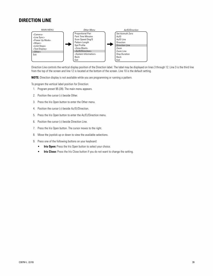
DIRECTION LINE
Direction Line controls the vertical display position of the Direction label. The label may be displayed on lines 3 through 12. Line 3 is the third line from the top of the screen and line 12 is located at the bottom of the screen. Line 10 is the default setting.
NOTE: Direction display is not available while you are programming or running a pattern.
To program the vertical label position for Direction:
1. Program preset 95 (28). The main menu appears.
2. Position the cursor (>) beside Other.
3. Press the Iris Open button to enter the Other menu.
4. Position the cursor (>) beside Az/El/Direction.
5. Press the Iris Open button to enter the Az/El/Direction menu.
6. Position the cursor (>) beside Direction Line.
7. Press the Iris Open button. The cursor moves to the right.
8. Move the joystick up or down to view the available selections.
9. Press one of the following buttons on your keyboard:
• Iris Open: Press the Iris Open button to select your choice.
• Iris Close: Press the Iris Close button if you do not want to change the setting.
Proportional Pan Park Time Minutes Scan Speed Deg/S Pattern Length Spd Profile<Zone Blank><Az/El/Direction><System Information>BackExit
Other Menu Az/El/DirectionSet Azimuth ZeroAz/ElAz/El LineDirectionDirection LineZoomZoom LineDisp DurationBackExit
MAIN MENU
<Camera><Line Sync><Power Up Mode><Wiper><Limit Stops><Text Display><Other>Exit
C307M-L (3/10) 39

DISPLAY DURATION
Display Duration programs the duration the Az/El, Direction, and Zoom labels are displayed on the monitor. The available settings for display duration include the following:
• Constant: The label is displayed continuously.
• 2 Seconds (default): The label is displayed for 2 seconds after PTZ functions end.
• 5 Seconds: The label is displayed for 5 seconds after PTZ functions end.
• 10 Seconds: The label is displayed for 10 seconds after PTZ functions end.
To program the display duration for the Az/El, Direction, and Zoom labels:
1. Program preset 95 (28). The main menu appears.
2. Position the cursor (>) beside Other.
3. Press the Iris Open button to enter the Other menu.
4. Position the cursor (>) beside Az/El/Direction.
5. Press the Iris Open button to enter the Az/El/Direction menu.
6. Position the cursor (>) beside Disp Duration.
7. Press the Iris Open button. The cursor moves to the right.
8. Move the joystick up or down to view the available selections.
9. Press one of the following buttons on your keyboard:
• Iris Open: Press the Iris Open button to select your choice.
• Iris Close: Press the Iris Close button if you do not want to change the setting.
Proportional Pan Park Time Minutes Scan Speed Deg/S Pattern Length Spd Profile<Zone Blank><Az/El/Direction><System Information>BackExit
Other Menu Az/El/DirectionSet Azimuth ZeroAz/ElAz/El LineDirectionDirection LineZoomZoom LineDisp DurationBackExit
MAIN MENU
<Camera><Line Sync><Power Up Mode><Wiper><Limit Stops><Text Display><Other>Exit
40 C307M-L (3/10)

FIELD ALIGNMENT(Applies only to 24X and 35X models.)
Field alignment determines whether the camera produces progressive segmented frame output (PsF) or interlaced frame output. Analog video from the camera is always output in separate fields as required for compatibility. This feature allows PsF to be recombined by an encoding device without a time difference between fields, as is typically seen from interlaced analog video output. Enabling field align requires that the encoding device you are using always combines the odd and even fields in the specified order.
There are three field alignment settings:
• Off (default): Field alignment is disabled. Use this setting if you are using an analog device/system or a digital encoder that does not support PsF.
• Odd: Arranges the odd field for a particular video frame before the even field for that frame.
• Even: Arranges the even field for a particular video frame before the odd field for that frame.
NOTE: If you enable field alignment by selecting Odd or Even, you must disable any deinterlacing settings for the encoding device to achieve maximum resolution.
To configure the field alignment:
1. Program preset 95 (28). The main menu appears.
2. Position the cursor (>) beside Camera.
3. Press the Iris Open button to enter the Camera menu.
4. Position the cursor (>) beside Field Alignment.
5. Press the Iris Open button. The cursor moves to the right, beside the current field alignment setting.
6. Move the joystick up or down to change the setting.
7. Press one of the following buttons on your keyboard:
• Iris Open: Press the Iris Open button to select your choice.
• Iris Close: Press the Iris Close button if you do not want to change the setting.
Backlight CompZoom LimitReset CameraWDRField Alignment
<AGC/Auto Iris/ToL>NextBackExit
Camera MenuMAIN MENU
<Camera><Line Sync><Power Up Mode><Wiper><Limit Stops><Text Display><Other>Exit
C307M-L (3/10) 41

GAIN LIMIT
The gain limit sets the maximum level for the automatic gain control. Increasing the level will increase the signal level and increase the noise level of the picture.
To change the gain:
1. Program preset 95 (28). The main menu appears.
2. Position the cursor (>) beside Camera.
3. Press the Iris Open button to enter the Camera menu.
4. Position the cursor (>) beside AGC/Auto Iris/ToL.
5. Press the Iris Open button to enter the AGC/Auto Iris/ToL menu.
6. Position the cursor (>) beside Gain Limit.
7. Press the Iris Open button. The cursor moves to the right, beside the current gain level setting (a numeric value).
8. Move the joystick up or down to change the level.
9. Press one of the following buttons on your keyboard:
• Iris Open: Press the Iris Open button to select your choice.
• Iris Close: Press the Iris Close button if you do not want to change the setting.
Backlight CompZoom Limit
Reset CameraWDRField Alignment
<AGC/Auto Iris/ToL>NextBackExit
Camera Menu
Gain LimitAuto-Iris ModeAuto-Iris LevelAuto-Iris PeakType of Lighting
BackExit
AGC/Auto Iris/ToL MenuMAIN MENU
<Camera><Line Sync><Power Up Mode><Wiper><Limit Stops><Text Display><Other>Exit
42 C307M-L (3/10)

IMAGE STABILIZER(Applies only to 35X models.)
Image stabilization is a feature of the camera that can compensate for some forms of external influences. In all cases, care should be taken to make sure that any Esprit system is mounted to a rigid location.
The image stabilization feature will not correct for all ranges of vibration. If the available settings fail to eliminate the vibration seen in the video, other measures should be taken to isolate the vibration or to seek a more rigid mounting location.
NOTE: When image stabilization is activated, wide dynamic range is disabled and digital zoom is limited.
There are three settings for image stabilization:
• 5 Hz: This setting corrects for vibrations at the 5 Hz frequency.
• 10 Hz: This setting corrects for vibrations at the 10 Hz frequency.
• Off: The setting is disabled.
NOTE: Apply each of the settings to the camera to see which one best addresses the vibration that is affecting the video quality.
To change the image stabilizer setting:
1. Program preset 95 (28). The main menu appears.
2. Position the cursor (>) beside Camera.
3. Press the Iris Open button to enter the Camera menu.
4. Position the cursor (>) beside Next.
5. Press the Iris Open button to enter the Next menu.
6. Position the cursor (>) beside Img Stabilizer.
7. Press the Iris Open button. The cursor moves to the right, beside the current image stabilizer setting.
8. Move the joystick up or down to change the setting.
9. Press one of the following buttons on your keyboard:
• Iris Open: Press the Iris Open button to select your choice.
• Iris Close: Press the Iris Close button if you do not want to change the setting.
Backlight CompZoom LimitReset CameraWDRField Alignment
<AGC/Auto Iris/ToL>NextBackExit
Camera Menu
LowLight LimitShutter SpeedAuto Focus ModeSure FocusLowLight Focus Img Stabilizer <IR Filt/Sharp/Wht Bal>NextBackExit
Next MenuMAIN MENU
<Camera><Line Sync><Power Up Mode><Wiper><Limit Stops><Text Display><Other>Exit
C307M-L (3/10) 43

IR FILTER MODE(Applies only to 24X and 35X models.)
There are two settings for the IR filter mode:
• Auto: IR filter switches in and out automatically.
NOTES:
• Automatic shutter speed must be set to Auto for the IR filter to operate automatically. If the automatic shutter speed is disabled, the IR filter setting will automatically switch to OFF.
• If IR filter mode is changed to Auto, the Shutter Speed setting will return to Auto.
• Off: IR filter is manually operated. The following presets are used to manually operate the IR filter.
• Preset 88: Filter IN (color)
• Preset 89: Filter OUT (monochrome)
To change the lR filter mode:
1. Program preset 95 (28). The main menu appears.
2. Position the cursor (>) beside Camera.
3. Press the Iris Open button to enter the Camera menu.
4. Position the cursor (>) beside Next.
5. Press the Iris Open button to enter the Next menu.
6. Position the cursor (>) beside IR Filt/Sharp/Wht Bal.
7. Press the Iris Open button to enter the IR Filt/Sharp/Wht Bal menu.
8. Position the cursor (>) beside IR Filter Mode.
9. Press the Iris Open button. The cursor moves to the right, beside the word Auto or Off.
10. Move the joystick up or down to toggle between Auto and Off.
11. Press one of the following buttons on your keyboard:
• Iris Open: Press the Iris Open button to select your choice.
• Iris Close: Press the Iris Close button if you do not want to change the setting.
Backlight CompZoom LimitReset CameraWDRField Alignment
<AGC/Auto Iris/ToL>NextBackExit
Camera Menu Auto SharpnessSharpnessAuto White BalR GainB GainIR Filter ModeAuto IR Level
BackExit
IR Filt/Sharp/Wht Bal MenuMAIN MENU
<Camera><Line Sync><Power Up Mode><Wiper><Limit Stops><Text Display><Other>Exit
LowLight LimitShutter SpeedAuto Focus ModeSure FocusLowLight FocusImg Stabilizer<IR Filt/Sharp/Wht Bal>NextBackExit
Next Menu
44 C307M-L (3/10)

LIMIT STOPS
NOTE: Limit stops are inactive while setting items in the program menu (e.g. azimuth zero, scan limits, manual pan limits).
TURNING LIMIT STOPS ON OR OFF
To change the limit stop mode:
1. Program preset 95 (28). The main menu appears.
2. Position the cursor (>) beside Limit Stop.
3. Press the Iris Open button to enter the Limit Stop menu.
4. Position the cursor (>) beside Limit Stops.
5. Press the Iris Open button. The cursor moves to the right, beside On or Off.
6. Move the joystick up or down to toggle between On and Off.
7. Press one of the following buttons on your keyboard:
• Iris Open: Press the Iris Open button to select your choice.
• Iris Close: Press the Iris Close button if you do not want to change the setting.
PROGRAMMING LIMIT STOPS
Manual Limit StopsWhen manual limit stops are set, pan operation (using a joystick or pan/tilt keys) stops when a limit stop is reached. The manual limit stops can be set in one of two ways:
• At the controller by programming presets 90 (23) and 91 (24)
• At the controller by programming the Limit Stops menu
PresetsRefer to the documentation for your control system for programming presets, and then do the following:
1. Make sure limit stops are turned ON, then exit the menu.
2. Push the joystick left until you reach the limit you want the camera to go to on the left.
3. Program preset 90 (23).
4. Push the joystick right to the limit you want the camera to go to on the right.
5. Program preset 91 (24).
Setting presets 90 (23) and 91 (24) to the same point disables manual limit stops.
NOTE: Programming preset 90 (23) disables the manual limit stops until preset 91 (24) is set. Preset 90 (23) is the left manual limit and preset 91 (24) is the right manual limit.
Limit Stops Set Man LimitsClear Man LimitsSet Scan LimitsClear Scan LimitsBackExit
Limit Stop MenuMAIN MENU
<Camera><Line Sync><Power Up Mode><Wiper><Limit Stops><Text Display><Other>Exit
C307M-L (3/10) 45

Limit Stops MenuThe manual pan limit stops can be set at the controller using the Limit Stops menu:
1. Program preset 95 (28). The main menu appears.
2. Position the cursor (>) beside Limit Stop.
3. Press the Iris Open button to enter the Limit Stop menu.
4. Move the cursor to Set Man Limits and press the Iris Open button. PRESS IRIS OPEN TO SET LEFT LIMIT appears.
5. Move the pan/tilt to the desired left limit position and press the Iris Open button to set the left manual limit. PRESS IRIS OPEN TO SET RIGHT LIMIT appears.
6. Move the pan/tilt to the desired right limit position and press the Iris Open button to set the right manual limit.
7. Exit the Limit Stop menu.
Clear Manual StopsTo clear the manual limit stops:
1. Program preset 95 (28). The main menu appears.
2. Position the cursor (>) beside Limit Stop.
3. Press the Iris Open button to enter the Limit Stop menu.
4. Move the cursor to Clear Man Limits and press the Iris Open button. The cursor will flash to an asterisk (*) briefly to indicate the limits have been disabled.
Scan Limit StopsWhen scan limit stops are set, the pan/tilt reverses direction during random, frame, or autoscanning when a limit stop is reached. The manual scan limit stops can be set in one of two ways:
• At the controller by programming presets 92 and 93
• At the controller by programming the Limit Stops menu
Limit Stops MenuThe manual pan limit stops can be set at the controller using the Limit Stops menu:
1. Program preset 95 (28). The main menu appears.
2. Position the cursor (>) beside Limit Stop.
3. Press the Iris Open button to enter the Limit Stop menu.
4. Move the cursor to Set Scan Limits and press the Iris Open button. PRESS IRIS OPEN TO SET LEFT LIMIT appears.
5. Move the pan/tilt to the desired left limit position and press the Iris Open button to set the left manual limit. PRESS IRIS OPEN TO SET RIGHT LIMIT appears.
6. Move the pan/tilt to the desired right limit position and press the Iris Open button to set the right scan limit.
7. Exit the Limit Stop menu.
Clear Scan Limit StopsTo clear the scan limit stops, move the cursor to Clear Scan Limits and press the Iris Open button. The cursor will flash to an asterisk (*) briefly to indicate the limits have been disabled.
46 C307M-L (3/10)

LINE SYNCHRONIZATION
If cameras are out of phase with each other, they may produce what appears to be vertical roll when switching between cameras.
There are two settings for line synchronization:
• On: Adjust the synchronization of the power line voltage so that it is in phase with other cameras.
• Off: The system synchronizes to an internal clock.
To change the line synchronization settings:
1. Program preset 95 (28). The main menu appears.
2. Position the cursor (>) beside Line Sync.
3. Press the Iris Open button. The Line Sync menu appears.
4. Position the cursor (>) beside one of the following choices. Press the Iris Open button.
• Line Sync: The cursor moves to one of two choices: on or off. Move the joystick up or down to toggle between them. Press the Iris Open button to select the choice. If you changed to off, the camera may reset itself as it adjusts to the new synchronization. If the camera resets, it will only affect the line synchronization. It will not change any other camera parameters, such as auto focus or auto iris. Press the Iris Close button if you do not want to change the setting.
• Line Sync Phase: The cursor moves to a numeric value. Move the joystick up or down to change the value. The value represents the phase angle in tenths of a degree between 0 and 359 degrees. For example, 900 is 90 degrees, 1200 is 120 degrees, and 2400 is 240 degrees. Press the Iris Open button on your keyboard to select your choice. The Line Sync setting changes to ON. The camera may reset or the picture on your monitor may wiggle when you change the phase angle. If the camera resets, it will only affect the line synchronization. It will not change any other camera parameters, such as auto focus or auto iris. Press the Iris Close button if you do not want to change the setting.
Line Sync Line Sync PhaseBackExit
Line Sync MenuMAIN MENU
<Camera><Line Sync><Power Up Mode><Wiper><Limit Stops><Text Display><Other>Exit
C307M-L (3/10) 47

LOWLIGHT FOCUS
This setting allows the camera to focus better in infrared lighting. The available settings are Def (default), 850nm, or 950nm
NOTE: Low light does not mean no light. Some type of illumination is required.
To change the LowLight focus:
1. On the main menu, move the joystick up or down to position the cursor (>) beside Camera.
2. Press the Iris Open button to enter the Camera menu.
3. Position the cursor (>) beside Next.
4. Press the Iris Open button to go to the Next menu.
5. Position the cursor (>) beside LowLight focus.
6. Press the Iris Open button. The cursor moves to the right, beside the current LowLight focus.
7. Move the joystick up or down to choose the LowLight focus.
8. Press one of the following buttons on your keyboard:
• Iris Open: Press the Iris Open button to select your choice.
• Iris Close: Press the Iris Close button if you do not want to change the setting.
Backlight CompZoom LimitReset CameraWDRField Alignment
<AGC/Auto Iris/ToL>NextBackExit
Camera MenuMAIN MENU
<Camera><Line Sync><Power Up Mode><Wiper><Limit Stops><Text Display><Other>Exit
LowLight LimitShutter SpeedAuto Focus ModeLow Light Focus Img Stabilizer <IR Filt/Sharp/Wht Bal>NextBackExit
Next Menu
48 C307M-L (3/10)

LOWLIGHT LIMIT
This setting determines the maximum length of time the shutter will remain open automatically in low light conditions. There are six choices:
2 = 1/2 second 8 = 1/8 second 30 = 1/30 second
4 = 1/4 second 15 = 1/15 second 60 = 1/60 second
NOTES:
• Low light does not mean no light. Some type of illumination is required.
• Auto focus is automatically turned off when the shutter speed is longer than 1/8 of a second.
To change the LowLight limit:
1. On the main menu, move the joystick up or down to position the cursor (>) beside Camera.
2. Press the Iris Open button to enter the Camera menu.
3. Position the cursor (>) beside Next.
4. Press the Iris Open button to go to the Next menu.
5. Position the cursor (>) beside LowLight Limit.
6. Press the Iris Open button. The cursor moves to the right, beside the current LowLight Limit.
7. Move the joystick up or down to choose the LowLight Limit.
8. Press one of the following buttons on your keyboard:
• Iris Open: Press the Iris Open button to select your choice.
• Iris Close: Press the Iris Close button if you do not want to change the setting.
Backlight CompZoom LimitReset CameraWDRField Alignment
<AGC/Auto Iris/ToL>NextBackExit
Camera MenuMAIN MENU
<Camera><Line Sync><Power Up Mode><Wiper><Limit Stops><Text Display><Other>Exit
LowLight LimitShutter SpeedAuto Focus ModeSure FocusLowLight FocusImg Stabilizer<IR Filt/Sharp/Wht Bal>NextBackExit
Next Menu
C307M-L (3/10) 49

LOW LUX NOISE REDUCTION(Applies only to 24X and 35X models)
Low lux noise reduction helps to reduce video noise in low light scenes. When enabled, low lux noise reduction is directly affected by the AGC settings for the dome system.
There are two low lux noise reduction settings:
• On (default): Low lux noise reduction is enabled. As the scene darkens and AGC increases, the noise reduction effect automatically increases. As noise reduction increases, you may also notice some afterimaging and a slight reduction in color saturation.
• Off: Low lux noise reduction is disabled.
To change the low lux noise reduction setting:
1. On the main menu, move the joystick up or down to position the cursor (>) beside Camera.
2. Press the Iris Open button to enter the Camera menu.
3. Position the cursor (>) beside Next.
4. Press the Iris Open button to go to the Next menu.
5. Position the cursor (>) beside Next.
6. Press the Iris Open button to go to the second Next menu.
7. Position the cursor (>) beside Low Lux NR.
8. Press the Iris Open button. The cursor moves to the right, beside On or Off.
9. Move the joystick up or down to toggle between On and Off.
10. Press one of the following buttons on your keyboard:
• Iris Open: Press the Iris Open button to select your choice.
• Iris Close: Press the Iris Close button if you do not want to change the setting.
Backlight CompZoom LimitReset CameraWDRField Alignment
<AGC/Auto Iris/ToL>NextBackExit
Camera MenuPicture ModeLow Lux NR
BackExit
Next MenuMAIN MENU
<Camera><Line Sync><Power Up Mode><Wiper><Limit Stops><Text Display><Other>Exit
LowLight LimitShutter SpeedAuto Focus ModeSure FocusLowLight Focus Img Stabilizer <IR Filt/Sharp/Wht Bal>NextBackExit
Next Menu
50 C307M-L (3/10)

PARK TIME MINUTES
This feature causes the system to park at preset 1 after a programmed number of minutes of control inactivity. The time can be set from 1 minute to 720 minutes (12 hours), or it can be set to zero, which disables this feature.
NOTE: Preset 1 must be programmed for the dome to park.
To change the park time:
1. Program preset 95 (28). The main menu appears.
2. Position the cursor (>) beside Other.
3. Press the Iris Open button to enter the Other menu.
4. Position the cursor (>) beside Park Time Minutes.
5. Press the Iris Open button. The cursor moves to the right, beside the current park time.
6. Move the joystick up or down to change the park time.
7. Press one of the following buttons on your keyboard:
• Iris Open: Press the Iris Open button to select your choice.
• Iris Close: Press the Iris Close button if you do not want to change the setting.
Proportional Pan Park Time Minutes Scan Speed Deg/S Pattern Length Spd Profile<Zone Blank><Az/El/Direction><System Information>BackExit
Other MenuMAIN MENU
<Camera><Line Sync><Power Up Mode><Wiper><Limit Stops><Text Display><Other>Exit
C307M-L (3/10) 51

PATTERN LENGTH
The Esprit can do the following:
• One full pattern: 1.5, 3, or 6 minutes long
• Two half patterns: 0.75, 1.5, or 3 minutes long
This pattern can consist of any standard pan, tilt, or lens command. Presets, flip, and Turbo are not allowed in a pattern. Zone scan can be enabled while running a pattern.
NOTE: Digital zoom and proportional pan are not available during a pattern.
To set the pattern length:
1. Program preset 95 (28). The main menu appears.
2. Position the cursor (>) beside Other.
3. Press the Iris Open button to enter the menu entitled Other.
4. Position the cursor (>) beside Pattern Length.
5. Press the Iris Open button. The cursor moves to the right, beside the number of minutes (1.5, 3, or 6).
6. Move the joystick up or down to toggle through the number of minutes (1.5, 3, or 6).
7. Press one of the following buttons on your keyboard:
• Iris Open: Press the Iris Open button to select your choice.
• Iris Close: Press the Iris Close button if you do not want to change the setting.
WARNING: If the pattern length is changed, all patterns that were stored are erased.
Proportional Pan Park Time Minutes Scan Speed Deg/S Pattern Length Spd Profile<Zone Blank><Az/El/Direction><System Information>BackExit
Other MenuMAIN MENU
<Camera><Line Sync><Power Up Mode><Wiper><Limit Stops><Text Display><Other>Exit
52 C307M-L (3/10)

PICTURE MODE(Applies only to 35X models.)
Picture mode offers enhanced color and brightness depending on the scene.
To change the picture mode setting:
1. On the main menu, move the joystick up or down to position the cursor (>) beside Camera.
2. Press the Iris Open button to enter the Camera menu.
3. Position the cursor (>) beside Next.
4. Press the Iris Open button to go to the Next menu.
5. Position the cursor (>) beside Next.
6. Press the Iris Open button to go to the second Next menu.
7. Position the cursor (>) beside Picture Mode.
8. Press the Iris Open button. The cursor moves to the right, beside 1 or 2.
9. Move the joystick up or down to toggle between 1 and 2.
NOTE: The scene on your monitor will darken temporarily when you change the picture mode setting.
10. Press one of the following buttons on your keyboard:
• Iris Open: Press the Iris Open button to select your choice.
• Iris Close: Press the Iris Close button if you do not want to change the setting.
NOTE: Picture Mode is set to 1 when Type of Lighting is T2.
Backlight CompZoom LimitReset CameraWDRField Alignment
<AGC/Auto Iris/ToL>NextBackExit
Camera MenuPicture ModeLow Lux NR
BackExit
Next MenuMAIN MENU
<Camera><Line Sync><Power Up Mode><Wiper><Limit Stops><Text Display><Other>Exit
LowLight LimitShutter SpeedAuto Focus ModeSure FocusLowLight Focus Img Stabilizer <IR Filt/Sharp/Wht Bal>NextBackExit
Next Menu
C307M-L (3/10) 53

POWER-UP MODE
This feature lets the dome resume a desired condition following power-up. The menu includes the following choices.
• Default: On power-up, the system goes through a configuration cycle and stops at zero reference, showing “Configuration Done,” address, and mode settings on the screen.
• Park: The system moves to preset 1 when the power-up sequence finishes. The only text on the screen is the preset label (if any is programmed).
• Scan Auto: The system initiates scan mode when the power-up sequence finishes. Again, there is no text.
• Scan Frame: The system initiates a frame scan when the power-up sequence finishes.
• Scan Rand: The system initiates a random scan when the power-up sequence finishes.
• Full Pat: The system initiates its programmed pattern when the power-up sequence finishes. The length can be set to 1.5, 3, or 6 minutes.
• Half Pat 1: The system initiates the first half-pattern when the power-up sequence finishes. The length can be set to 0.75, 1.5, or 3 minutes.
• Half Pat 2: The system initiates the second half-pattern when the power-up sequence finishes. The length can be set to 0.75, 1.5, or 3 minutes.
The default setting is Default.
To select the power-up mode:
1. Program preset 95 (28). The main menu appears.
2. Position the cursor (>) beside Power Up.
3. Press the Iris Open button to enter the Power-Up menu.
4. Press the Iris Open button to move the cursor to the right.
5. Move the joystick up or down to cycle through the selections. Stop on the item you want to select.
6. Press one of the following buttons on your keyboard:
• Iris Open: Press the Iris Open button to select your choice.
• Iris Close: Press the Iris Close button if you do not want to change the setting.
Power UpBackExit
Power-Up MenuMAIN MENU
<Camera><Line Sync><Power Up Mode><Wiper><Limit Stops><Text Display><Other>Exit
54 C307M-L (3/10)

PROPORTIONAL PAN
There are two proportional pan modes:
• On: Enables the proportional pan mode. The amount of zoom controls the pan/tilt. At telephoto zoom settings, the pan/tilt speeds will be slower for a given amount of joystick deflection than at wide zoom settings. This keeps the image from moving too fast on the monitor when there is a large amount of zoom.
• Off: Disables proportional pan mode. The pan speed will not depend on the amount of zoom.
NOTE: Proportional pan is not available during a pattern.
To change the proportional pan mode:
1. Program preset 95 (28). The main menu appears.
2. Position the cursor (>) beside Other.
3. Press the Iris Open button to enter the Other menu.
4. Position the cursor (>) beside Proportional Pan.
5. Press the Iris Open button. The cursor moves to the right, beside the word On or Off.
6. Move the joystick up or down to toggle between On and Off.
7. Press one of the following buttons on your keyboard:
• Iris Open: Press the Iris Open button to select your choice.
• Iris Close: Press the Iris Close button if you do not want to change the setting.
Proportional Pan Park Time Minutes Scan Speed Deg/S Pattern Length Spd Profile<Zone Blank><Az/El/Direction><System Information>BackExit
Other MenuMAIN MENU
<Camera><Line Sync><Power Up Mode><Wiper><Limit Stops><Text Display><Other>Exit
C307M-L (3/10) 55

RESET CAMERA
Resetting the camera returns the settings to their defaults.
NOTE: The values in the following table for Gain Limit, Auto Iris, Level, and Peak are typical.
Turning off power does not reset the camera. Camera settings are retained in memory. When the power is turned back on, the settings will be the same as they were when the power was turned off.
To reset the camera:
1. Program preset 95 (28). The main menu appears.
2. Position the cursor (>) beside Camera.
3. Press the Iris Open button to enter the Camera menu.
4. Position the cursor (>) beside Reset Camera.
5. Press the Iris Open button to reset the camera.
35X Models 24X Models 22X Models
Defa
ult S
ettin
g
Backlight Comp Off Off Off
Zoom Limit No default No default No default
Gain/AGCGain Limit 23 25 25
Auto IrisModeLevelPeak
NTSCAuto11616
PALAuto488
NTSCAuto10616
PALAuto9616
Auto6616
Low Light Limit 8 2 2
Shutter Speed Auto Auto Auto
Auto Focus Mode Auto Auto Auto
IR FilterIR Filter ModeAuto IR Level
AutoDusk
OffDusk
N/AN/A
SharpnessAuto SharpnessSharpness
OnNo defaults
OnNo default
OnNo default
White BalanceAuto White BalR GainB Gain
OnNo defaultNo default
OnNo defaultNo default
OnNo defaultNo default
Backlight CompZoom LimitReset CameraWDRField Alignment
<AGC/Auto Iris/ToL>NextBackExit
Camera MenuMAIN MENU
<Camera><Line Sync><Power Up Mode><Wiper><Limit Stops><Text Display><Other>Exit
56 C307M-L (3/10)
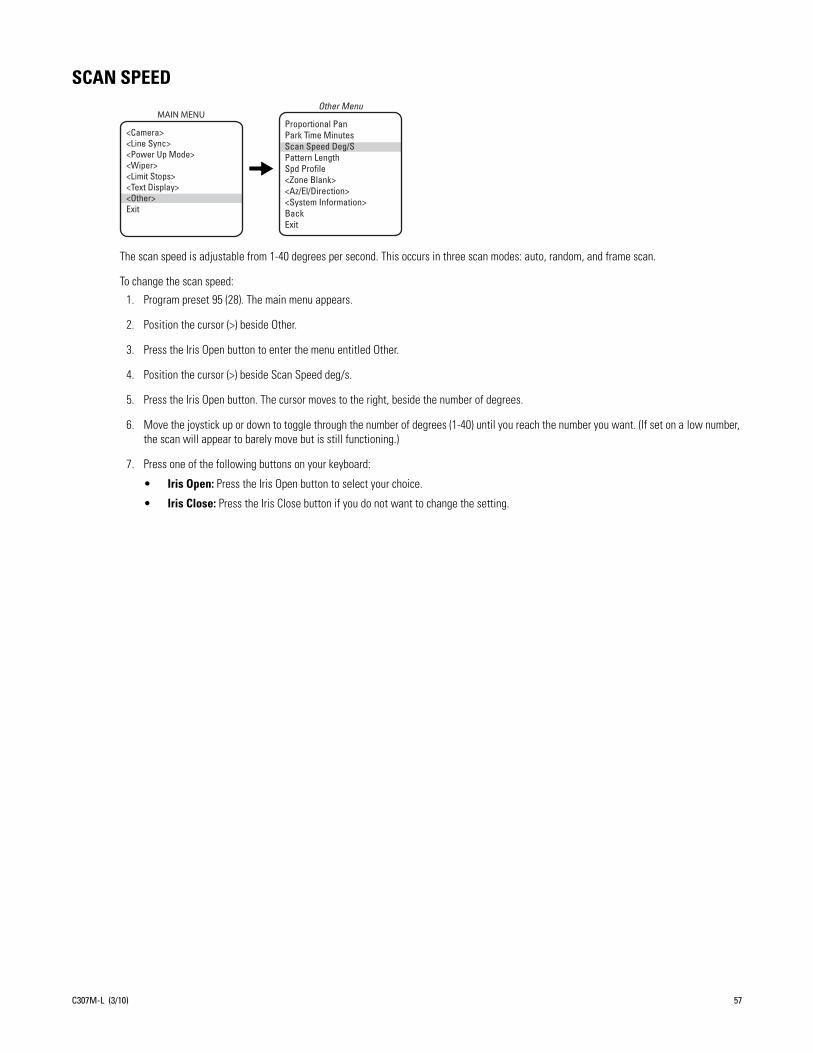
SCAN SPEED
The scan speed is adjustable from 1-40 degrees per second. This occurs in three scan modes: auto, random, and frame scan.
To change the scan speed:
1. Program preset 95 (28). The main menu appears.
2. Position the cursor (>) beside Other.
3. Press the Iris Open button to enter the menu entitled Other.
4. Position the cursor (>) beside Scan Speed deg/s.
5. Press the Iris Open button. The cursor moves to the right, beside the number of degrees.
6. Move the joystick up or down to toggle through the number of degrees (1-40) until you reach the number you want. (If set on a low number, the scan will appear to barely move but is still functioning.)
7. Press one of the following buttons on your keyboard:
• Iris Open: Press the Iris Open button to select your choice.
• Iris Close: Press the Iris Close button if you do not want to change the setting.
Proportional Pan Park Time Minutes Scan Speed Deg/S Pattern Length Spd Profile<Zone Blank><Az/El/Direction><System Information>Back Exit
Other MenuMAIN MENU
<Camera><Line Sync><Power Up Mode><Wiper><Limit Stops><Text Display><Other>Exit
C307M-L (3/10) 57

SHARPNESS
Use the Sharpness setting to manually set the sharpness of the camera.
To manually set the sharpness of the camera:
1. Program preset 95 (28). The main menu appears.
2. Position the cursor (>) beside Camera.
3. Press the Iris Open button to enter the Camera menu.
4. Position the cursor (>) beside Next.
5. Press the Iris Open button to enter the Next menu.
6. Position the cursor (>) beside IR Filt/Sharp/Wht Bal.
7. Press the Iris Open button to enter the IR Filt/Sharp/Wht Bal menu.
8. Position the cursor (>) beside Sharpness.
9. Press the Iris Open button. The cursor moves to the right, beside the numeric value.
10. Move the joystick up or down to toggle through the sharpness settings.
NOTE: As you change the value, you will see the sharpness change.
11. Press one of the following buttons on your keyboard:
• Iris Open: Press the Iris Open button to select your choice.
• Iris Close: Press the Iris Close button if you do not want to change the setting.
NOTE: If the Auto Sharpness setting is On, it will change to Off when you select a Sharpness value.
Backlight CompZoom LimitReset CameraWDRField Alignment
<AGC/Auto Iris/ToL>NextBackExit
Camera MenuAuto SharpnessSharpnessAuto White BalR GainB GainIR Filter ModeAuto IR Level
BackExit
IR Filt/Sharp/Wht Bal MenuMAIN MENU
<Camera><Line Sync><Power Up Mode><Wiper><Limit Stops><Text Display><Other>Exit
LowLight LimitShutter SpeedAuto Focus ModeSure FocusLowLight FocusImg Stabilizer<IR Filt/Sharp/Wht Bal>NextBackExit
Next Menu
58 C307M-L (3/10)

SHUTTER SPEED
There are several electronic shutter speed settings:
Auto1/21/41/81/151/301/601/1001/1201/1801/2501/5001/10001/20001/40001/10,0001/30,000
In the Auto setting the camera controls the shutter speed automatically. Increasing the shutter speed lowers the light sensitivity, but rapidly moving objects will be less blurred.
NOTE: (Applies only to 24X and 35X.) If the IR Filter Mode is set to Auto, the Shutter Speed setting will default automatically to the Auto setting.
To change the electronic shutter speed settings:
1. Program preset 95 (28). The main menu appears.
2. Position the cursor (>) beside Camera.
3. Press the Iris Open button to enter the Camera menu.
4. Position the cursor (>) beside Next.
5. Press the Iris Open button to go to the Next menu.
6. Position the cursor (>) beside Shutter Speed.
7. Press the Iris Open button.
8. The cursor moves to the right, beside the current shutter speed.
9. Move the joystick up or down to choose the shutter speed.
10. Press one of the following buttons on your keyboard:
• Iris Open: Press the Iris Open button to select your choice.
• Iris Close: Press the Iris Close button if you do not want to change the setting.
Backlight CompZoom LimitReset CameraWDRField Alignment
<AGC/Auto Iris/ToL>NextBackExit
Camera MenuMAIN MENU
<Camera><Line Sync><Power Up Mode><Wiper><Limit Stops><Text Display><Other>Exit
LowLight Limit Shutter SpeedAuto Focus ModeSure FocusLowLight FocusImg Stabilizer<IR Filt/Sharp/Wht Bal>NextBackExit
Next Menu
C307M-L (3/10) 59

SPEED PROFILE
This feature allows the operator to set the wind speed conditions for the location of the Esprit system. You can set two wind speed profiles of 50 mph or 90 mph in which the system will remain operational. In both settings, the pan speed will be a maximum of 40 degrees per second. The difference will be in the Turbo and preset pan speeds. The Turbo and preset pan speeds are 100 degrees per second in the 50 mph wind profile setting and 50 degrees per second in the 90 mph profile.
To set the speed profile:
1. Program preset 95 (28). The main menu appears.
2. Position the cursor (>) beside Other.
3. Press the Iris Open button to enter the menu entitled Other.
4. Position the cursor (>) beside Spd Profile.
5. Press the Iris Open button. The cursor moves to the right, beside the wind speed (50 mph wind or 90 mph wind).
6. Move the joystick up or down to toggle through the wind speeds (50 mph wind or 90 mph wind).
7. Press one of the following buttons on your keyboard:
• Iris Open: Press the Iris Open button to select your choice.
• Iris Close: Press the Iris Close button if you do not want to change the setting.
Proportional Pan Park Time Minutes Scan Speed Deg/S Pattern Length Spd Profile<Zone Blank><Az/El/Direction><System Information>BackExit
Other MenuMAIN MENU
<Camera><Line Sync><Power Up Mode><Wiper><Limit Stops><Text Display><Other>Exit
60 C307M-L (3/10)
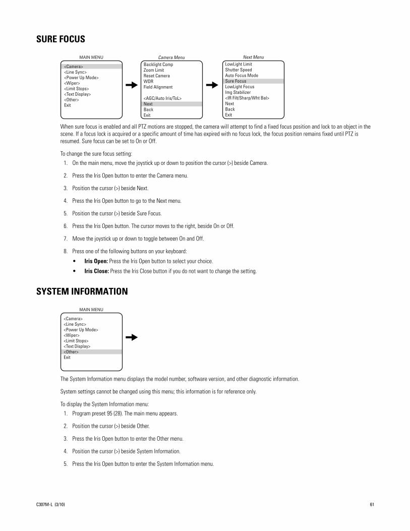
SURE FOCUS
When sure focus is enabled and all PTZ motions are stopped, the camera will attempt to find a fixed focus position and lock to an object in the scene. If a focus lock is acquired or a specific amount of time has expired with no focus lock, the focus position remains fixed until PTZ is resumed. Sure focus can be set to On or Off.
To change the sure focus setting:
1. On the main menu, move the joystick up or down to position the cursor (>) beside Camera.
2. Press the Iris Open button to enter the Camera menu.
3. Position the cursor (>) beside Next.
4. Press the Iris Open button to go to the Next menu.
5. Position the cursor (>) beside Sure Focus.
6. Press the Iris Open button. The cursor moves to the right, beside On or Off.
7. Move the joystick up or down to toggle between On and Off.
8. Press one of the following buttons on your keyboard:
• Iris Open: Press the Iris Open button to select your choice.
• Iris Close: Press the Iris Close button if you do not want to change the setting.
SYSTEM INFORMATION
The System Information menu displays the model number, software version, and other diagnostic information.
System settings cannot be changed using this menu; this information is for reference only.
To display the System Information menu:
1. Program preset 95 (28). The main menu appears.
2. Position the cursor (>) beside Other.
3. Press the Iris Open button to enter the Other menu.
4. Position the cursor (>) beside System Information.
5. Press the Iris Open button to enter the System Information menu.
Backlight CompZoom LimitReset CameraWDRField Alignment
<AGC/Auto Iris/ToL>NextBackExit
Camera MenuMAIN MENU
<Camera><Line Sync><Power Up Mode><Wiper><Limit Stops><Text Display><Other>Exit
LowLight LimitShutter SpeedAuto Focus ModeSure FocusLowLight Focus Img Stabilizer <IR Filt/Sharp/Wht Bal>NextBackExit
Next Menu
MAIN MENU
<Camera><Line Sync><Power Up Mode><Wiper><Limit Stops><Text Display><Other>Exit
C307M-L (3/10) 61

TEXT DISPLAY
NOTE: When displaying more than one type of text, be sure that each type of text is set to display on a different row. If more than one type of text is set to display on the same row, text overlap may occur.
EDITING THE TITLE TEXTTo edit the title text:
1. Program preset 95 (28). The main menu appears.
2. Position the cursor (>) beside Text Display.
3. Press the Iris Open button to enter the Text Display menu.
4. Position the cursor (>) beside Edit Title Text.
5. Press the Iris Open button. The cursor moves to the top of the screen.
6. Move the joystick left or right to position the cursor in the desired location.
7. Move the joystick up or down to scroll through uppercase and lowercase letters and numbers.
8. Press one of the following buttons on your keyboard:
• Iris Open: Press the Iris Open button to select your choice.
• Iris Close: Press the Iris Close button if you do not want to change the setting.
DISPLAYING TITLE TEXTTo activate or deactivate the title text:
1. Program preset 95 (28). The main menu appears.
2. Position the cursor (>) beside Text Display.
3. Press the Iris Open button to enter the Text Display menu.
4. Position the cursor (>) beside Disp Title Text.
5. Press the Iris Open button. The cursor moves to the right.
6. Move the joystick up or down to toggle between Off and On.
7. Press one of the following buttons on your keyboard:
• Iris Open: Press the Iris Open button to select your choice.
• Iris Close: Press the Iris Close button if you do not want to change the setting.
SETTING TITLE TEXT ROWThe title text row is the line on the screen on which the title text is displayed. The available settings for the Title Text Row are rows 1 through 12.
To change the settings for title text row:
1. Program preset 95 (28). The main menu appears.
2. Position the cursor (>) beside Text Display.
MAIN MENU
<Edit Title Text>Disp Title TextTitle Text RowZone Text RowPreset Text RowBackExit
Text Display Menu
<Camera><Line Sync><Power Up Mode>*<Wiper><Limit Stops><Text Display><Other>Exit
62 C307M-L (3/10)

3. Press the Iris Open button to enter the Text Display menu.
4. Position the cursor (>) beside Title Text Row.
5. Press the Iris Open button. The cursor moves to the right.
6. Move the joystick up or down to toggle between available rows.
7. Press one of the following buttons on your keyboard:
• Iris Open: Press the Iris Open button to select your choice.
• Iris Close: Press the Iris Close button if you do not want to change the setting.
SETTING ZONE TEXT ROWThe zone text row is the line on the screen on which the zone text is displayed. The available settings for the Zone Text Row are rows 1 through 12.
To change the settings for zone text row:
1. Program preset 95 (28). The main menu appears.
2. Position the cursor (>) beside Text Display.
3. Press the Iris Open button to enter the Text Display menu.
4. Position the cursor (>) beside Zone Text Row.
5. Press the Iris Open button. The cursor moves to the right.
6. Move the joystick up or down to toggle between available rows
7. Press one of the following buttons on your keyboard:
• Iris Open: Press the Iris Open button to select your choice.
• Iris Close: Press the Iris Close button if you do not want to change the setting.
SETTING PRESET TEXT ROWThe preset text row is the line on the screen on which the preset text is displayed. The available settings for the Preset Text Row are rows 1 through 12.
To change the settings for preset text row:
1. Program preset 95 (28). The main menu appears.
2. Position the cursor (>) beside Text Display.
3. Press the Iris Open button to enter the Text Display menu.
4. Position the cursor (>) beside Preset Text Row.
5. Press the Iris Open button. The cursor moves to the right.
6. Move the joystick up or down to toggle between available rows.
7. Press one of the following buttons on your keyboard:
• Iris Open: Press the Iris Open button to select your choice.
• Iris Close: Press the Iris Close button if you do not want to change the setting.
C307M-L (3/10) 63

TYPE OF LIGHTING(Applies only to 35X models.)
There are two types of lighting settings:
• T1 (default): For use in outdoor applications.
• T2: For use in indoor applications.
NOTE: If T2 is selected, Picture Mode cannot be changed.
To set the type of lighting:
1. Program preset 95 (28). The main menu appears.
2. Position the cursor (>) beside Camera.
3. Press the Iris Open button to enter the Camera menu.
4. Position the cursor (>) beside AGC/Auto Iris/ToL.
5. Press the Iris Open button to go to the AGC/Auto Iris/ToL menu.
6. Position the cursor (>) beside Type of Lighting.
7. Press the Iris Open button. The cursor moves to the following line, beside T1 or T2.
8. Move the joystick up or down to make a selection.
9. Press one of the following buttons on your keyboard:
• Iris Open: Press the Iris Open button to select your choice.
• Iris Close: Press the Iris Close button if you do not want to change the setting.
Backlight CompZoom Limit
Reset CameraWDRField Alignment
<AGC/Auto Iris/ToL>NextBackExit
Camera Menu AGC/Auto Iris/ToL Menu
Gain LimitAuto-Iris ModeAuto-Iris LevelAuto-Iris PeakType of Lighting
BackExit
MAIN MENU
<Camera><Line Sync><Power Up Mode><Wiper><Limit Stops><Text Display><Other>Exit
64 C307M-L (3/10)

WHITE BALANCE
The available settings for white balance are Auto White Bal, R Gain, and B Gain.
1. Program preset 95 (28). The main menu appears.
2. Position the cursor (>) beside Camera.
3. Press the Iris Open button to enter the Camera menu.
4. Position the cursor (>) beside Next.
5. Press the Iris Open button to go to the Next menu.
6. Position the cursor (>) beside IR Filt/Sharp/Wht Bal.
7. Press the Iris Open button to enter the IR Filt/Sharp/Wht Bal menu.
8. Position the cursor (>) beside one of the following choices and press the Iris Open button.
• Auto White Bal: Automatically processes the viewed image to retain color balance over a color temperature range. The available settings for auto white balance are On or Off.
• R Gain: Adjusts the picture output in the red range.
• B Gain: Adjusts the picture output in the blue range.
9. Move the joystick up or down to make a selection.
10. Press one of the following buttons on your keyboard:
• Iris Open: Press the Iris Open button to select your choice.
• Iris Close: Press the Iris Close button if you do not want to change the setting.
Backlight CompZoom LimitReset CameraWDRField Alignment
<AGC/Auto Iris/ToL>NextBackExit
Camera MenuAuto SharpnessSharpnessAuto White BalR GainB GainIR Filter ModeAuto IR Level
BackExit
IR Filt/Sharp/Wht Bal MenuMAIN MENU
<Camera><Line Sync><Power Up Mode><Wiper><Limit Stops><Text Display><Other>Exit
LowLight LimitShutter SpeedAuto Focus ModeSure FocusLowLight FocusImg Stabilizer<IR Filt/Sharp/Wht Bal>NextBackExit
Next Menu
C307M-L (3/10) 65
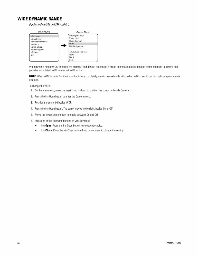
WIDE DYNAMIC RANGE(Applies only to 24X and 35X models.)
Wide dynamic range (WDR) balances the brightest and darkest sections of a scene to produce a picture that is better balanced in lighting and provides more detail. WDR can be set to Off or On.
NOTE: When WDR is set to On, the iris will not close completely even in manual mode. Also, when WDR is set to On, backlight compensation is disabled.
To change the WDR:
1. On the main menu, move the joystick up or down to position the cursor (>) beside Camera.
2. Press the Iris Open button to enter the Camera menu.
3. Position the cursor (>) beside WDR.
4. Press the Iris Open button. The cursor moves to the right, beside On or Off.
5. Move the joystick up or down to toggle between On and Off.
6. Press one of the following buttons on your keyboard:
• Iris Open: Press the Iris Open button to select your choice.
• Iris Close: Press the Iris Close button if you do not want to change the setting.
Backlight CompZoom LimitReset CameraWDRField Alignment
<AGC/Auto Iris/ToL>NextBackExit
Camera MenuMAIN MENU
<Camera><Line Sync><Power Up Mode><Wiper><Limit Stops><Text Display><Other>Exit
66 C307M-L (3/10)

WIPER
The available settings for wiper mode are Wiper Mode, Wiper Dwell, and Wiper Time.
To change the wiper settings:
1. Program preset 95 (28). The main menu appears.
2. Position the cursor (>) beside Wiper.
3. Press the Iris Open button to enter the Wiper menu.
4. Move the joystick up or down to position the cursor next to one of the wiper settings.
5. Press the Iris Open button. The cursor moves to the right.
6. Move the joystick up or down to toggle through the choices.
• Momentary Mode: To operate the wiper one full cycle, press the AUX 1 button on your controller. Each press of the button operates the wiper one full cycle, even if the AUX 1 button is latching. If AUX 1 is latching, the first press will activate the wiper (open the latch). Pressing AUX 1 a second time closes the latch, but will not cycle the wiper. Press the AUX 1 key again to cycle the wiper.
• Continuous Mode: To operate the wiper press the AUX 1 button on your controller. The wiper will continue to operate until the AUX 1 button is pressed again or until the programmed cycle is completed.
NOTE: CM9740 and CM9760 matrix systems only: For the wiper to operate in continuous mode, the AUX 1 function in the camera file must be set to latching. If the AUX 1 camera file is not latching, the wiper will only operate in momentary mode, even if the Esprit wiper is programmed for continuous operation. Refer to the operation manual supplied with the CM9740 or CM9760 matrix system for instructions.
• Wiper Dwell: The time between wiper cycles. The dwell time can be programmed from 2 to 255 seconds.
• Wiper Time: The length of the wiper cycle. Wiper time can be programmed from 2 to 1,440 minutes (2 minutes to 24 hours).
7. Press one of the following buttons on your keyboard:
• Iris Open: Press the Iris Open button to select your choice.
• Iris Close: Press the Iris Close button if you do not want to change the setting.
Wiper Mode Wiper Dwell <s> Wiper Time <m>BackExit
Wiper MenuMAIN MENU
<Camera><Line Sync><Power Up Mode><Wiper><Limit Stops><Text Display><Other>Exit
C307M-L (3/10) 67

ZONESBasic rules for setting zones:
1. Refer to the documentation for your control system to program zones.
2. Establish zones using the controller, prior to programming ZONE BLANK with the Esprit on-screen menu.
3. To accurately set zone areas, zoom wide to the maximum field of view.
4. Set zones moving the joystick left to right. The left position is always the start position.
ZONE BLANK
The Esprit system features on-screen programmable zone blanking. This feature lets you define any zone as blanked for video (viewing/recording).
Zones can be programmed to overlap each other, although this is not recommended. If you program two zones to overlap, the title of the zone with the highest priority (zone 8 is the highest, zone 1 is the lowest) will be displayed on the monitor. This rule also applies to blanked zones that overlap. The blanking status of the zone with the highest priority will determine if the area is blanked or not. Example: Zone 1 is blanked but a portion of the zone overlaps zone 8 which is not blanked. The overlapped portion of zone 1 will be displayed on the monitor with the zone 8 label.
There are two video zone blank settings:
• On: Enables video blanking.
• Off: Disables video blanking.
To change the video blank zone setting:
1. Program preset 95 (28). The main menu appears.
2. Position the cursor (>) beside Other.
3. Press the Iris Open button to enter the Other menu.
4. Position the cursor (>) beside Zone Blank.
5. Press the Iris Open button to enter the Zone Blank menu.
6. Position the cursor (>) beside the number of the zone for which you want to set the blank option.
7. Press the Iris Open button. The cursor moves to the right, beside the word On or Off.
8. Move the joystick up or down to toggle between the words On and Off.
9. Press one of the following buttons on your keyboard:
• Iris Open: Press the Iris Open button to select your choice.
• Iris Close: Press the Iris Close button if you do not want to change the setting.
Proportional Pan Park Time Minutes Scan Speed Deg/S Pattern LengthSpd Profile <Zone Blank><Az/El/Direction><System Information>BackExit
Other MenuVideo Blanking Zones1 Off 2 Off3 Off 4 Off5 Off 6 Off7 Off 8 Off
BackExit
Zone Blank MenuMAIN MENU
<Camera><Line Sync><Power Up Mode><Wiper><Limit Stops><Text Display><Other>Exit
68 C307M-L (3/10)

ZOOM
Zoom programs the horizontal display position of the Zoom label. The following settings are available for the Zoom label:
• Off: Label is not displayed.
• Left: Label is displayed on the left-hand side of the screen.
• Center (default): Label is displayed in the center of the screen.
• Right: Label is displayed on the right-hand side of the screen.
NOTE: Zoom display is not available while you are programming or running a pattern.
To program the horizontal label position for Zoom:
1. Program preset 95 (28). The main menu appears.
2. Position the cursor (>) beside Other.
3. Press the Iris Open button to enter the Other menu.
4. Position the cursor (>) beside Az/El/Direction.
5. Press the Iris Open button to enter the Az/El/Direction menu.
6. Position the cursor (>) beside Zoom.
7. Press the Iris Open button. The cursor moves to the right.
8. Move the joystick up or down to view the available selections.
9. Press one of the following buttons on your keyboard:
• Iris Open: Press the Iris Open button to select your choice.
• Iris Close: Press the Iris Close button if you do not want to change the setting.
Proportional Pan Park Time Minutes Scan Speed Deg/S Pattern Length Spd Profile<Zone Blank><Az/El/Direction><System Information>BackExit
Other MenuSet Azimuth ZeroAz/ElAz/El LineDirectionDirection LineZoomZoom LineDisp DurationBackExit
Az/El/DirectionMAIN MENU
<Camera><Line Sync><Power Up Mode><Wiper><Limit Stops><Text Display><Other>Exit
C307M-L (3/10) 69

ZOOM LIMIT
ES30C22/ES31C22 or ES30PC22/ES31PC22: 22X optical zoom and 12X digital zoom; can be set for 22X, 32X, 88X, 176X, 220X, or 264X
ES30CBW24/ES31CBW24 or EC30PCBW224/ES31PCBW24: 24X optical zoom and 12X digital zoom; can be set for 24X, 32X, 96X, 192X, 240X, or 288X
ES30CBW35/ES31CBW35 or ES30PCBW35/ES31PCBW35: 35X optical zoom and 12X digital zoom; can be set for 35X, 70X, 140X, 280X, 350X, or 420X
To change the zoom limit:
1. Program preset 95 (28). The main menu appears.
2. Position the cursor (>) beside Camera.
3. Press the Iris Open button to enter the Camera menu.
4. Position the cursor (>) beside Zoom Limit.
5. Press the Iris Open button. The cursor moves to the right, beside the current zoom limit.
6. Move the joystick up or down to choose the zoom limit.
7. Press one of the following buttons on your keyboard:
• Iris Open: Press the Iris Open button to select your choice.
• Iris Close: Press the Iris Close button if you do not want to change the setting.
Backlight CompZoom LimitReset CameraWDRField Alignment
<AGC/Auto Iris/ToL>NextBackExit
Camera MenuMAIN MENU
<Camera><Line Sync><Power Up Mode><Wiper><Limit Stops><Text Display><Other>Exit
70 C307M-L (3/10)

ZOOM LINE
Zoom Line controls the vertical display position of the Zoom label. The label may be displayed on lines 3 through 12. Line 3 is the third line from the top of the screen and line 12 is located at the bottom of the screen. Line 10 is the default setting.
NOTE: Zoom display is not available while you are programming or running a pattern.
To program the vertical label position for Zoom:
1. Program preset 95 (28). The main menu appears.
2. Position the cursor (>) beside Other.
3. Press the Iris Open button to enter the Other menu.
4. Position the cursor (>) beside Az/El/Direction.
5. Press the Iris Open button to enter the Az/El/Direction menu.
6. Position the cursor (>) beside Zoom Line.
7. Press the Iris Open button. The cursor moves to the right.
8. Move the joystick up or down to view the available selections.
9. Press one of the following buttons on your keyboard:
• Iris Open: Press the Iris Open button to select your choice.
• Iris Close: Press the Iris Close button if you do not want to change the setting.
Proportional Pan Park Time Minutes Scan Speed Deg/S Pattern Length Spd Profile<Zone Blank><Az/El/Direction><System Information>BackExit
Other MenuSet Azimuth ZeroAz/ElAz/El LineDirectionDirection LineZoomZoom LineDisp DurationBackExit
Az/El/DirectionMAIN MENU
<Camera><Line Sync><Power Up Mode><Wiper><Limit Stops><Text Display><Other>Exit
C307M-L (3/10) 71

Troubleshooting
Symptom: System does not operate.1. Check system input voltage.
2. The Esprit system is protected by a resettable overcurrent protective device located in the transformer module. Whenever a fault condition is experienced in the system causing excessive current flow through the protective device, a change occurs that will prevent current flow. The protective device will remain in this state as long as power is applied and the system fault remains. The protective device will reset itself after power has been removed for a few minutes and will operate normally when the system fault has been repaired.
3. Check the camera and lens power connections and video BNC connections.
Symptom: No control/sluggish control (Coaxitron)1. Check for correct type and length of coaxial cable.
2. Check for correct coaxial termination (refer to the controller manual to determine proper termination of video input). Normal load termination is 75 ohms. When looping through VCRs or multiplexers, make sure the signal is terminated at the end device. Some termination symptoms and problems are listed below.
3. If pan/tilt operation is sluggish, check the controller manual to make sure the control signal is set in the extended mode, not standard mode.
4. Check that the video is terminated.
Symptom: No control (RS-422)1. Check for correct cable type and length. The maximum cable distance for RS-422 communication over 24-gauge wire is 4,000 feet
(1,219 m). Pelco recommends using shielded twisted pairs, such as Belden 9843 or similar cable, that meets or exceeds the basic requirements for EIA RS-422 or RS-485 applications.
2. Check for correct wire connections between transmitting device (such as the CM6700 Series matrix system) and Esprit system receiver. Correct connections are from the transmitting device TX+ to Esprit system RX+ and from the transmitting device TX- to Esprit system RX-.
3. Check for correct DIP switch settings.
Symptom: Ground loopsGround loops are indicated by seeing 60 Hz noise on the video.
1. Check for resistance between the grounds of the keyboard and the system. Ideally, there should be zero ohms.
2. Remove the coaxial BNC connector and check for voltage between the BNC shield of the controller and the BNC shield of the system. No voltage should be detected.
It is recommended that a Pelco GIT100 ground isolation transformer be installed to eliminate the above problems.
Symptom Problem
Extremely bright video No termination or high resistance
Over contrast or contrast level of monitor needs to be increased to maximum for a good video image
Double termination (37.5 ohms)
72 C307M-L (3/10)

Symptom: No video or poor video1. Check the video and power connections to the camera.
2. Check for power to the camera from the Esprit system camera power output.
3. Check all coaxial BNC connectors from the camera to the monitor.
4. Make sure the controller is set for the correct camera-to-monitor viewing combination; for example, Camera 1 to Monitor 1. Refer to the controller manual for information.
5. Check for normal load termination of 75 ohms. When looping through VCRs or multiplexers, make sure the signal is terminated at the end device. Some termination symptoms and problems are listed below.
Symptom: Wiper does not work with Genex Multiplexer in Track Main modeIf you have a Genex®/KBD4000/Esprit with wiper combination, you must perform the following steps to make the wiper function when Genex is in Track Main mode:
1. Call the spot monitor.
2. Call the camera.
3. Press the auxiliary ON key.
MAINTENANCEClean the enclosure window periodically with a mild non-abrasive detergent in water and a soft cloth to help maintain picture clarity.
If operating problems are experienced with the system, refer to Troubleshooting on page 72.
The pan/tilt is IP 66 and NEMA 4X rated. The pan/tilt left side cover must be removed to gain access to the DIP switches. When the cover is correctly reinstalled, the rating will remain in effect.
If the window wiper assembly is installed, replace worn or deteriorated wiper blades immediately. At a minimum, replace wiper blade once a year.
To order replacement wiper blades or if further maintenance is required, contact Pelco’s Customer Service Department for assistance. Refer to the Product Warranty and Return Information.
NOTE: The system contains no user-serviceable parts. If there is a problem with your system, it must be returned to Pelco for servicing.
Symptom Problem
Extremely bright video No termination or high resistance
Over contrast or contrast level of monitor needs to be increased to maximum for a good video image
Double termination (37.5 ohms)
C307M-L (3/10) 73

AppendixNOTE: Esprit will sense and automatically select input from Coaxitron control signals in either the standard or extended mode. Therefore, the DIP switches settings have no effect on Coaxitron control signals.
*SW1-3 is not used; set it to the OFF position.
*SW1-4 is not used; set it to the OFF position.
Table A. Switch Settings for SW1
Baud RateSwitch Setting
SW1-1 SW1-2 SW1-3
2400 OFF OFF OFF*
4800 ON OFF OFF*
9600 OFF ON OFF*
2400 ON ON OFF*
Switch Setting
SW1-4 SW1-5 SW1-6 SW1-7 SW1-8
OFF* Note (1) Note (2) Note (3) Note (4)
NOTES:
(1) SW1-5 OFF For controllers that have more than 32 presets.ON For American Dynamics™ controllers (32 presets).
(2) SW1-6 OFF For all control systems except CM9502 with variable speed keyboards. For CM9502 with fixed speed keyboards, set switch
to OFF.ON For CM9502 with variable speed keyboards to get smoother joystick control.
(3) SW1-7 OFF RS-422 transmitter is not terminated.ON RS-422 transmitter is terminated.
(4) SW1-8 OFF 1.2 Vp-p video level.ON 1 Vp-p video level.
74 C307M-L (3/10)
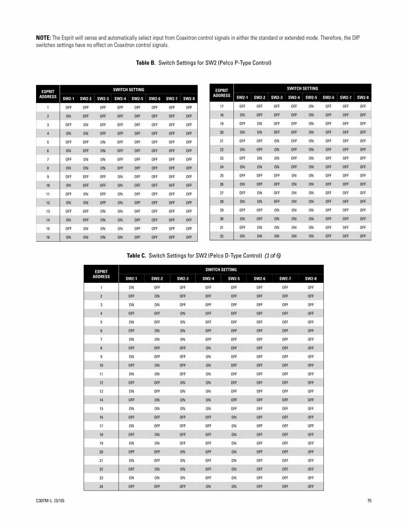
NOTE: The Esprit will sense and automatically select input from Coaxitron control signals in either the standard or extended mode. Therefore, the DIP switches settings have no effect on Coaxitron control signals.
Table B. Switch Settings for SW2 (Pelco P-Type Control)
Table C. Switch Settings for SW2 (Pelco D-Type Control) (1 of 6)
ESPRITADDRESS
SWITCH SETTING
SW2-1 SW2-2 SW2-3 SW2-4 SW2-5 SW2-6 SW2-7 SW2-8
1 ON OFF OFF OFF OFF OFF OFF OFF
2 OFF ON OFF OFF OFF OFF OFF OFF
3 ON ON OFF OFF OFF OFF OFF OFF
4 OFF OFF ON OFF OFF OFF OFF OFF
5 ON OFF ON OFF OFF OFF OFF OFF
6 OFF ON ON OFF OFF OFF OFF OFF
7 ON ON ON OFF OFF OFF OFF OFF
8 OFF OFF OFF ON OFF OFF OFF OFF
9 ON OFF OFF ON OFF OFF OFF OFF
10 OFF ON OFF ON OFF OFF OFF OFF
11 ON ON OFF ON OFF OFF OFF OFF
12 OFF OFF ON ON OFF OFF OFF OFF
13 ON OFF ON ON OFF OFF OFF OFF
14 OFF ON ON ON OFF OFF OFF OFF
15 ON ON ON ON OFF OFF OFF OFF
16 OFF OFF OFF OFF ON OFF OFF OFF
17 ON OFF OFF OFF ON OFF OFF OFF
18 OFF ON OFF OFF ON OFF OFF OFF
19 ON ON OFF OFF ON OFF OFF OFF
20 OFF OFF ON OFF ON OFF OFF OFF
21 ON OFF ON OFF ON OFF OFF OFF
22 OFF ON ON OFF ON OFF OFF OFF
23 ON ON ON OFF ON OFF OFF OFF
24 OFF OFF OFF ON ON OFF OFF OFF
ESPRITADDRESS
SWITCH SETTING
SW2-1 SW2-2 SW2-3 SW2-4 SW2-5 SW2-6 SW2-7 SW2-8
1 OFF OFF OFF OFF OFF OFF OFF OFF
2 ON OFF OFF OFF OFF OFF OFF OFF
3 OFF ON OFF OFF OFF OFF OFF OFF
4 ON ON OFF OFF OFF OFF OFF OFF
5 OFF OFF ON OFF OFF OFF OFF OFF
6 ON OFF ON OFF OFF OFF OFF OFF
7 OFF ON ON OFF OFF OFF OFF OFF
8 ON ON ON OFF OFF OFF OFF OFF
9 OFF OFF OFF ON OFF OFF OFF OFF
10 ON OFF OFF ON OFF OFF OFF OFF
11 OFF ON OFF ON OFF OFF OFF OFF
12 ON ON OFF ON OFF OFF OFF OFF
13 OFF OFF ON ON OFF OFF OFF OFF
14 ON OFF ON ON OFF OFF OFF OFF
15 OFF ON ON ON OFF OFF OFF OFF
16 ON ON ON ON OFF OFF OFF OFF
ESPRITADDRESS
SWITCH SETTING
SW2-1 SW2-2 SW2-3 SW2-4 SW2-5 SW2-6 SW2-7 SW2-8
17 OFF OFF OFF OFF ON OFF OFF OFF
18 ON OFF OFF OFF ON OFF OFF OFF
19 OFF ON OFF OFF ON OFF OFF OFF
20 ON ON OFF OFF ON OFF OFF OFF
21 OFF OFF ON OFF ON OFF OFF OFF
22 ON OFF ON OFF ON OFF OFF OFF
23 OFF ON ON OFF ON OFF OFF OFF
24 ON ON ON OFF ON OFF OFF OFF
25 OFF OFF OFF ON ON OFF OFF OFF
26 ON OFF OFF ON ON OFF OFF OFF
27 OFF ON OFF ON ON OFF OFF OFF
28 ON ON OFF ON ON OFF OFF OFF
29 OFF OFF ON ON ON OFF OFF OFF
30 ON OFF ON ON ON OFF OFF OFF
31 OFF ON ON ON ON OFF OFF OFF
32 ON ON ON ON ON OFF OFF OFF
C307M-L (3/10) 75

25 ON OFF OFF ON ON OFF OFF OFF
26 OFF ON OFF ON ON OFF OFF OFF
27 ON ON OFF ON ON OFF OFF OFF
28 OFF OFF ON ON ON OFF OFF OFF
29 ON OFF ON ON ON OFF OFF OFF
30 OFF ON ON ON ON OFF OFF OFF
31 ON ON ON ON ON OFF OFF OFF
32 OFF OFF OFF OFF OFF ON OFF OFF
33 ON OFF OFF OFF OFF ON OFF OFF
34 OFF ON OFF OFF OFF ON OFF OFF
35 ON ON OFF OFF OFF ON OFF OFF
36 OFF OFF ON OFF OFF ON OFF OFF
37 ON OFF ON OFF OFF ON OFF OFF
38 OFF ON ON OFF OFF ON OFF OFF
39 ON ON ON OFF OFF ON OFF OFF
40 OFF OFF OFF ON OFF ON OFF OFF
41 ON OFF OFF ON OFF ON OFF OFF
42 OFF ON OFF ON OFF ON OFF OFF
43 ON ON OFF ON OFF ON OFF OFF
44 OFF OFF ON ON OFF ON OFF OFF
45 ON OFF ON ON OFF ON OFF OFF
46 OFF ON ON ON OFF ON OFF OFF
47 ON ON ON ON OFF ON OFF OFF
48 OFF OFF OFF OFF ON ON OFF OFF
49 ON OFF OFF OFF ON ON OFF OFF
50 OFF ON OFF OFF ON ON OFF OFF
51 ON ON OFF OFF ON ON OFF OFF
52 OFF OFF ON OFF ON ON OFF OFF
53 ON OFF ON OFF ON ON OFF OFF
54 OFF ON ON OFF ON ON OFF OFF
55 ON ON ON OFF ON ON OFF OFF
56 OFF OFF OFF ON ON ON OFF OFF
57 ON OFF OFF ON ON ON OFF OFF
58 OFF ON OFF ON ON ON OFF OFF
59 ON ON OFF ON ON ON OFF OFF
60 OFF OFF ON ON ON ON OFF OFF
61 ON OFF ON ON ON ON OFF OFF
62 OFF ON ON ON ON ON OFF OFF
63 ON ON ON ON ON ON OFF OFF
64 OFF OFF OFF OFF OFF OFF ON OFF
65 ON OFF OFF OFF OFF OFF ON OFF
66 OFF ON OFF OFF OFF OFF ON OFF
67 ON ON OFF OFF OFF OFF ON OFF
68 OFF OFF ON OFF OFF OFF ON OFF
69 ON OFF ON OFF OFF OFF ON OFF
70 OFF ON ON OFF OFF OFF ON OFF
71 ON ON ON OFF OFF OFF ON OFF
72 OFF OFF OFF ON OFF OFF ON OFF
73 ON OFF OFF ON OFF OFF ON OFF
Table C. Switch Settings for SW2 (Pelco D-Type Control) (2 of 6)
ESPRITADDRESS
SWITCH SETTING
SW2-1 SW2-2 SW2-3 SW2-4 SW2-5 SW2-6 SW2-7 SW2-8
76 C307M-L (3/10)

74 OFF ON OFF ON OFF OFF ON OFF
75 ON ON OFF ON OFF OFF ON OFF
76 OFF OFF ON ON OFF OFF ON OFF
77 ON OFF ON ON OFF OFF ON OFF
78 OFF ON ON ON OFF OFF ON OFF
79 ON ON ON ON OFF OFF ON OFF
80 OFF OFF OFF OFF ON OFF ON OFF
81 ON OFF OFF OFF ON OFF ON OFF
82 OFF ON OFF OFF ON OFF ON OFF
83 ON ON OFF OFF ON OFF ON OFF
84 OFF OFF ON OFF ON OFF ON OFF
85 ON OFF ON OFF ON OFF ON OFF
86 OFF ON ON OFF ON OFF ON OFF
87 ON ON ON OFF ON OFF ON OFF
88 OFF OFF OFF ON ON OFF ON OFF
89 ON OFF OFF ON ON OFF ON OFF
90 OFF ON OFF ON ON OFF ON OFF
91 ON ON OFF ON ON OFF ON OFF
92 OFF OFF ON ON ON OFF ON OFF
93 ON OFF ON ON ON OFF ON OFF
94 OFF ON ON ON ON OFF ON OFF
95 ON ON ON ON ON OFF ON OFF
96 OFF OFF OFF OFF OFF ON ON OFF
97 ON OFF OFF OFF OFF ON ON OFF
98 OFF ON OFF OFF OFF ON ON OFF
99 ON ON OFF OFF OFF ON ON OFF
100 OFF OFF ON OFF OFF ON ON OFF
101 ON OFF ON OFF OFF ON ON OFF
102 OFF ON ON OFF OFF ON ON OFF
103 ON ON ON OFF OFF ON ON OFF
104 OFF OFF OFF ON OFF ON ON OFF
105 ON OFF OFF ON OFF ON ON OFF
106 OFF ON OFF ON OFF ON ON OFF
107 ON ON OFF ON OFF ON ON OFF
108 OFF OFF ON ON OFF ON ON OFF
109 ON OFF ON ON OFF ON ON OFF
110 OFF ON ON ON OFF ON ON OFF
111 ON ON ON ON OFF ON ON OFF
112 OFF OFF OFF OFF ON ON ON OFF
113 ON OFF OFF OFF ON ON ON OFF
114 OFF ON OFF OFF ON ON ON OFF
115 ON ON OFF OFF ON ON ON OFF
116 OFF OFF ON OFF ON ON ON OFF
117 ON OFF ON OFF ON ON ON OFF
118 OFF ON ON OFF ON ON ON OFF
119 ON ON ON OFF ON ON ON OFF
120 OFF OFF OFF ON ON ON ON OFF
121 ON OFF OFF ON ON ON ON OFF
122 OFF ON OFF ON ON ON ON OFF
Table C. Switch Settings for SW2 (Pelco D-Type Control) (3 of 6)
ESPRITADDRESS
SWITCH SETTING
SW2-1 SW2-2 SW2-3 SW2-4 SW2-5 SW2-6 SW2-7 SW2-8
C307M-L (3/10) 77

123 ON ON OFF ON ON ON ON OFF
124 OFF OFF ON ON ON ON ON OFF
125 ON OFF ON ON ON ON ON OFF
126 OFF ON ON ON ON ON ON OFF
127 ON ON ON ON ON ON ON OFF
128 OFF OFF OFF OFF OFF OFF OFF ON
129 ON OFF OFF OFF OFF OFF OFF ON
130 OFF ON OFF OFF OFF OFF OFF ON
131 ON ON OFF OFF OFF OFF OFF ON
132 OFF OFF ON OFF OFF OFF OFF ON
133 ON OFF ON OFF OFF OFF OFF ON
134 OFF ON ON OFF OFF OFF OFF ON
135 ON ON ON OFF OFF OFF OFF ON
136 OFF OFF OFF ON OFF OFF OFF ON
137 ON OFF OFF ON OFF OFF OFF ON
138 OFF ON OFF ON OFF OFF OFF ON
139 ON ON OFF ON OFF OFF OFF ON
140 OFF OFF ON ON OFF OFF OFF ON
141 ON OFF ON ON OFF OFF OFF ON
142 OFF ON ON ON OFF OFF OFF ON
143 ON ON ON ON OFF OFF OFF ON
144 OFF OFF OFF OFF ON OFF OFF ON
145 ON OFF OFF OFF ON OFF OFF ON
146 OFF ON OFF OFF ON OFF OFF ON
147 ON ON OFF OFF ON OFF OFF ON
148 OFF OFF ON OFF ON OFF OFF ON
149 ON OFF ON OFF ON OFF OFF ON
150 OFF ON ON OFF ON OFF OFF ON
151 ON ON ON OFF ON OFF OFF ON
152 OFF OFF OFF ON ON OFF OFF ON
153 ON OFF OFF ON ON OFF OFF ON
154 OFF ON OFF ON ON OFF OFF ON
155 ON ON OFF ON ON OFF OFF ON
156 OFF OFF ON ON ON OFF OFF ON
157 ON OFF ON ON ON OFF OFF ON
158 OFF ON ON ON ON OFF OFF ON
159 ON ON ON ON ON OFF OFF ON
160 OFF OFF OFF OFF OFF ON OFF ON
161 ON OFF OFF OFF OFF ON OFF ON
162 OFF ON OFF OFF OFF ON OFF ON
163 ON ON OFF OFF OFF ON OFF ON
164 OFF OFF ON OFF OFF ON OFF ON
165 ON OFF ON OFF OFF ON OFF ON
166 OFF ON ON OFF OFF ON OFF ON
167 ON ON ON OFF OFF ON OFF ON
168 OFF OFF OFF ON OFF ON OFF ON
169 ON OFF OFF ON OFF ON OFF ON
170 OFF ON OFF ON OFF ON OFF ON
171 ON ON OFF ON OFF ON OFF ON
Table C. Switch Settings for SW2 (Pelco D-Type Control) (4 of 6)
ESPRITADDRESS
SWITCH SETTING
SW2-1 SW2-2 SW2-3 SW2-4 SW2-5 SW2-6 SW2-7 SW2-8
78 C307M-L (3/10)

172 OFF OFF ON ON OFF ON OFF ON
173 ON OFF ON ON OFF ON OFF ON
174 OFF ON ON ON OFF ON OFF ON
175 ON ON ON ON OFF ON OFF ON
176 OFF OFF OFF OFF ON ON OFF ON
177 ON OFF OFF OFF ON ON OFF ON
178 OFF ON OFF OFF ON ON OFF ON
179 ON ON OFF OFF ON ON OFF ON
180 OFF OFF ON OFF ON ON OFF ON
181 ON OFF ON OFF ON ON OFF ON
182 OFF ON ON OFF ON ON OFF ON
183 ON ON ON OFF ON ON OFF ON
184 OFF OFF OFF ON ON ON OFF ON
185 ON OFF OFF ON ON ON OFF ON
186 OFF ON OFF ON ON ON OFF ON
187 ON ON OFF ON ON ON OFF ON
188 OFF OFF ON ON ON ON OFF ON
189 ON OFF ON ON ON ON OFF ON
190 OFF ON ON ON ON ON OFF ON
191 ON ON ON ON ON ON OFF ON
192 OFF OFF OFF OFF OFF OFF ON ON
193 ON OFF OFF OFF OFF OFF ON ON
194 OFF ON OFF OFF OFF OFF ON ON
195 ON ON OFF OFF OFF OFF ON ON
196 OFF OFF ON OFF OFF OFF ON ON
197 ON OFF ON OFF OFF OFF ON ON
198 OFF ON ON OFF OFF OFF ON ON
199 ON ON ON OFF OFF OFF ON ON
200 OFF OFF OFF ON OFF OFF ON ON
201 ON OFF OFF ON OFF OFF ON ON
202 OFF ON OFF ON OFF OFF ON ON
203 ON ON OFF ON OFF OFF ON ON
204 OFF OFF ON ON OFF OFF ON ON
205 ON OFF ON ON OFF OFF ON ON
206 OFF ON ON ON OFF OFF ON ON
207 ON ON ON ON OFF OFF ON ON
208 OFF OFF OFF OFF ON OFF ON ON
209 ON OFF OFF OFF ON OFF ON ON
210 OFF ON OFF OFF ON OFF ON ON
211 ON ON OFF OFF ON OFF ON ON
212 OFF OFF ON OFF ON OFF ON ON
213 ON OFF ON OFF ON OFF ON ON
214 OFF ON ON OFF ON OFF ON ON
215 ON ON ON OFF ON OFF ON ON
216 OFF OFF OFF ON ON OFF ON ON
217 ON OFF OFF ON ON OFF ON ON
218 OFF ON OFF ON ON OFF ON ON
219 ON ON OFF ON ON OFF ON ON
220 OFF OFF ON ON ON OFF ON ON
Table C. Switch Settings for SW2 (Pelco D-Type Control) (5 of 6)
ESPRITADDRESS
SWITCH SETTING
SW2-1 SW2-2 SW2-3 SW2-4 SW2-5 SW2-6 SW2-7 SW2-8
C307M-L (3/10) 79

221 ON OFF ON ON ON OFF ON ON
222 OFF ON ON ON ON OFF ON ON
223 ON ON ON ON ON OFF ON ON
224 OFF OFF OFF OFF OFF ON ON ON
225 ON OFF OFF OFF OFF ON ON ON
226 OFF ON OFF OFF OFF ON ON ON
227 ON ON OFF OFF OFF ON ON ON
228 OFF OFF ON OFF OFF ON ON ON
229 ON OFF ON OFF OFF ON ON ON
230 OFF ON ON OFF OFF ON ON ON
231 ON ON ON OFF OFF ON ON ON
232 OFF OFF OFF ON OFF ON ON ON
233 ON OFF OFF ON OFF ON ON ON
234 OFF ON OFF ON OFF ON ON ON
235 ON ON OFF ON OFF ON ON ON
236 OFF OFF ON ON OFF ON ON ON
237 ON OFF ON ON OFF ON ON ON
238 OFF ON ON ON OFF ON ON ON
239 ON ON ON ON OFF ON ON ON
240 OFF OFF OFF OFF ON ON ON ON
241 ON OFF OFF OFF ON ON ON ON
242 OFF ON OFF OFF ON ON ON ON
243 ON ON OFF OFF ON ON ON ON
244 OFF OFF ON OFF ON ON ON ON
245 ON OFF ON OFF ON ON ON ON
246 OFF ON ON OFF ON ON ON ON
247 ON ON ON OFF ON ON ON ON
248 OFF OFF OFF ON ON ON ON ON
249 ON OFF OFF ON ON ON ON ON
250 OFF ON OFF ON ON ON ON ON
251 ON ON OFF ON ON ON ON ON
252 OFF OFF ON ON ON ON ON ON
253 ON OFF ON ON ON ON ON ON
254 OFF ON ON ON ON ON ON ON
Table C. Switch Settings for SW2 (Pelco D-Type Control) (6 of 6)
ESPRITADDRESS
SWITCH SETTING
SW2-1 SW2-2 SW2-3 SW2-4 SW2-5 SW2-6 SW2-7 SW2-8
80 C307M-L (3/10)

Specifications
ELECTRICALInput Voltage 24, 120, or 230 VAC, 50/60 Hz; switch selectable for 120/230 VAC inputs; reset feature enables when
power becomes unstable or interrupted
Power Requirements Maximum power consumption is 70 VA per system
Heater and Defroster Thermostatically controlled heater consumes 10 W; cycles on at 40°F (5°C) and off at 60°F (16°C)
Defogger The window defogger consumes 3 W; cycles on at 70°F (21°C) and off at 85°F (29°C)
Electrical Connections 2 power source connections made at mount location with wire splices and 1 ground wire splice; 1 BNC receptacle and 4 wire splices at mount location for RS-422 D and P protocols; 2 wire splices for open collector auxiliary output
Aux 2 Open collector output with 2-second activation; connected relay must require no more than 32 VDC and 40 mA to energize relay coil; wire length between Esprit and relay must be less than 100 ft (30 m)
MECHANICALPan Movement 360° continuous pan rotation
Vertical Tilt Unobstructed +33° to -83°
Variable Pan/Tilt SpeedPan 0.1° to 40°/sec variable-speed operation, 100°/sec TurboTilt 0.1° to 20°/sec variable-speed operation
Preset SpeedsPan 100°/secTilt 30°/sec
Camera Mounting Integrated camera sled assembly
Latches 1 link-lock, No. 3 stainless-steel latch; can be secured with padlock (not supplied)
CAMERASScanning System 2:1 interlace
Image Sensor 1/4-inch
Effective Pixels NTSC PALES30C22/ES31C22 768 (H) x 494 (V) 752 (H) x 582 (V)ES30CBW24/ES31CBW24 768 (H) x 494 (V) 752 (H) x 582 (V)ES30CBW35/ES31CBW35 768 (H) x 494 (V) 752 (H) x 582 (V)ES30PC22/ES31PC22 768 (H) x 494 (V) 752 (H) x 582 (V)ES30PCBW24/ES31PCBW24 768 (H) x 494 (V) 752 (H) x 582 (V)ES30PCBW35/ES31PCBW35 768 (H) x 494 (V) 752 (H) x 582 (V)
Horizontal Resolution NTSC PALES30C22/ES31C22 >470 TV lines >460 TV linesES30CBW24/ES31CBW24 >520 TV lines >520 TV linesES30CBW35/ES31CBW35 >540 TV lines >540 TV linesES30PC22/ES31PC22 >470 TV lines >460 TV linesES30PCBW24/ES31PCBW24 >520 TV lines >520 TV linesES30PCBW35/ES31PCBW35 >540 TV lines >540 TV lines
C307M-L (3/10) 81

Focal LengthES30C22/ES31C22 4 ~ 88 mm opticalES30CBW24/ES31CBW24 3.8 ~ 91.2 mm opticalES30CBW35/ES31CBW35 3.4 ~ 119 mm optical
ES30PC22/ES31PC22 4 ~ 88 mm opticalES30PCBW24/ES31PCBW24 3.8 ~ 91.2 mm opticalES30PCBW35/ES31PCBW35 3.4 ~ 119 mm optical
Zoom RatioES30C22/ES31C22 22X optical zoom, 10X digital zoomES30CBW24/ES31CBW24 24X optical zoom, 10X digital zoomES30CBW35/ES31CBW35 35X optical zoom, 12X digital zoom
ES30PC22/ES31PC22 22X optical zoom, 10X digital zoomES30PCBW24/ES31PCBW24 24X optical zoom, 10X digital zoomES30PCBW35/ES31PCBW35 35X optical zoom, 12X digital zoom
Digital Slow Shutter Auto/manual speed selection
Horizontal Angle of ViewES30C22/ES31C22 47° at 4 mm wide zoom; 2° at 88 mm telephoto zoomES30CBW24/ES31CBW24 50.7° at 3.8 mm wide zoom; 2.3° at 91.2 mm telephoto zoomES30CBW35/ES31CBW35 55.8° at 3.4 mm wide zoom; 1.7° at 119 mm telephoto zoom
ES30PC22/ES31PC22 47° at 4 mm wide zoom; 2° at 88 mm telephoto zoomES30PCBW24/ES31PCBW24 50.7° at 3.8 mm wide zoom; 2.3° at 91.2 mm telephoto zoomES30PCBW35/ES31PCBW35 55.8° at 3.4 mm wide zoom; 1.7° at 119 mm telephoto zoom
Focus Automatic and manual override
SensitivityES30C22/ES31C22 0.02 lux at 1/2-second shutter speed (NTSC)
0.02 lux at 1/1.5-second shutter speed (PAL)ES30CBW24/ES31CBW24 0.005 lux at 1/2-second shutter speed (color, NTSC/PAL)
0.015 lux at 1/60-second shutter speed (B-W, NTSC/PAL)0.0005 lux at 1/2-second shutter speed (B-W, NTSC/PAL)
ES30CBW35/ES31CBW35 0.55 lux at 1/60-second shutter speed (color, NTSC)0.063 lux at 1/4-second shutter speed (color, NTSC)0.00018 lux at 1/2-second shutter speed (B-W, NTSC)0.50 lux at 1/50-second shutter speed (color, PAL)0.062 lux at 1/3-second shutter speed (color, PAL)0.00014 lux at 1/1.5-second shutter speed (B-W, NTSC)
ES30PC22/ES31PC22 0.02 lux at 1/2-second shutter speed (NTSC)0.02 lux at 1/1.5-second shutter speed (PAL)
ES30PCBW24/ES31PCBW24 0.005 lux at 1/2-second shutter speed (color, NTSC/PAL)0.015 lux at 1/60-second shutter speed (B-W, NTSC/PAL)0.0005 lux at 1/2-second shutter speed (B-W, NTSC/PAL)
ES30PCBW35/ES31PCBW35 0.55 lux at 1/60-second shutter speed (color, NTSC)0.063 lux at 1/4-second shutter speed (color, NTSC)0.00018 lux at 1/2-second shutter speed (B-W, NTSC)0.50 lux at 1/50-second shutter speed (color, PAL)0.062 lux at 1/3-second shutter speed (color, PAL)0.00014 lux at 1/1.5-second shutter speed (B-W, NTSC)
Synchronization System AC line lock, phase adjustable through remote control*
White Balance Automatic with manual override*
Shutter Speed 1/2 to 1/30,000 (NTSC)1/1.5 to 1/30,000 (PAL)
Iris Control Automatic with manual override*
82 C307M-L (3/10)

Gain ControlES30C22/ES31C22 Automatic/OFF*ES30CBW24/ES31CBW24 Automatic/OFF*ES30CBW35/ES31CBW35 Automatic/OFF*
ES30PC22/ES31PC22 Automatic/OFF*ES30PCBW24/ES31PCBW24 Automatic/OFF*ES30PCBW35/ES31PCBW35 Automatic/OFF*
Video Output 1 Vp-p, 75 ohms
Signal-to-Noise RatioES30C22/ES31C22 50 dBES30CBW24/ES31CBW24 50 dBES30CBW35/ES31CBW35 50 dB
ES30PC22/ES31PC22 50 dBES30PCBW24/ES31PCBW24 50 dBES30PCBW35/ES31PCBW35 50 dB
GENERALConstruction
System Die-cast, extruded and sheet aluminum; stainless steel hardwareEWM Wall Mount AluminumEPA Pedestal Adapter Aluminum
FinishSystem Gray polyester powder coat, anodizedEWM Wall Mount Gray polyester powder coatEPA Pedestal Adapter Gray polyester powder coat
Viewing Window 0.23-inch (5.84 mm) thick, optically clear, polycarbonate with proprietary impact resistant UV rated coating
Window Viewing Area 2-inch (5 cm) diameter
Operating Temperature -50° to 122°F (-45° to 50°C) for sustained system operation or 140°F (60°C) absolute maximum. Within two hours after power-up, the entire unit can de-ice and be operational from a temperature of -13°F (-25°C).
Operating Environment Will remain operational in 90 mph wind conditions; withstands 130 mph
Weight With Pedestal Adapter With Wall MountStandard w/IOP 20 lb (9.0 kg) 22 lb (9.9 kg)With Wiper and IOP 21 lb (9.5 kg) 23 lb (10.4 kg)
*Manual control of camera setup functions can be done with CM6700, CM8500, CM9500, CM9760 and MPT9500 controllers, but not with CM7500, MPT9000 or KBD9000 controllers.
(Design and product specifications subject to change without notice.)
NOTE: VALUES IN PARENTHESES ARE CENTIMETERS;ALL OTHERS ARE INCHES.
5.2(13.3)
13.3(33.9)
3.9(9.9)
14.6(37.0)
9.8(24.9)
3.6(9.1)
17.5(44.3)
7.9(20.0)
7.7(19.7)
C307M-L (3/10) 83
REVISION HISTORY
Manual # Date CommentsC307M 9/00 Original version.C307M-A 3/01 Added RS-422 and wiper functions material to the Troubleshooting section.C307M-B 8/02 Revised per ECO 02-8063.C307M-C 9/02 Revised model descriptions and specifications.C307M-D 11/02 Revised installation instructions for addition of alignment label.C307M-E 6/03 Added 24 VAC wire chart.C307M-F 8/03 Revised per ECO 03-9210 for new camera design.C307M-G 2/04 Referenced wire clamps per ECO 04-9710. Revised signal to noise ratio for the ES30C22/ES31C22.C307M-H 1/05 DIP switch SW1-8 functionality changed to video level per ECO 02-8186.C307M-I 11/05 Added operation and programming information. Added information on ES30CBW24/ES31CBW24. Updated layout. C307M-J 5/06 Removed information on ES30CBW18/ES31CBW18. Updated layout. C307M-K 11/07 Added information on ES30CBW35/ES31CBW35.C307M-L 3/10 Removed information on ES30CBW16/ES31CBW16. Added information on new settings including field alignment, low lux noise reduction, picture mode, sure focus,
system information, and wide dynamic range. Applied new template and merged C311M-O information with C307M-L.
Pelco, the Pelco logo, Camclosure, Coaxitron, Digital Sentry, Endura, Esprit, ExSite, Genex, Intelli-M, Legacy, and Spectra are registered trademarks of Pelco, Inc. © Copyright 2010, Pelco, Inc. All rights reserved.Spectra III and Sarix are trademarks of Pelco, Inc.DLP is a registered trademark of Texas Instruments Incorporated.All product names and services identified throughout this document are trademarks or registered trademarks of their respective companies. The absence of a trademark or registered trademark from this document does not constitute a waiver of intellectual property rights.
84 C307M-L (3/10)

The materials used in the manufacture of this document and its components are compliant to the requirements of Directive 2002/95/EC.
This equipment contains electrical or electronic components that must be recycled properly to comply with Directive 2002/96/EC of the European Union regarding the disposal of waste electrical and electronic equipment (WEEE). Contact your local dealer for procedures for recycling this equipment.
PRODUCT WARRANTY AND RETURN INFORMATION
WARRANTYPelco will repair or replace, without charge, any merchandise proved defective inmaterial or workmanship for a period of one year after the date of shipment.
Exceptions to this warranty are as noted below:• Five years:
– Fiber optic products– Unshielded Twisted Pair (UTP) transmission products– CC3701H-2, CC3701H-2X, CC3751H-2, CC3651H-2X, MC3651H-2, and
MC3651H-2X camera models• Three years:
– Pelco-designed fixed network cameras and network dome cameras withSarix™ technology.
– Pelco-branded fixed camera models (CCC1390H Series, C10DN Series,C10CH Series, and IP3701H Series)
– EH1500 Series enclosures– Spectra® IV products (including Spectra IV IP)– Camclosure® Series (IS, ICS, IP) integrated camera systems– DX Series digital video recorders (except DX9000 Series which is covered
for a period of one year), DVR5100 Series digital video recorders, DigitalSentry® Series hardware products, DVX Series digital video recorders, andNVR300 Series network video recorders
– Endura® Series distributed network-based video products– Genex® Series products (multiplexers, server, and keyboard)– PMCL200/300/400 Series LCD monitors– PMCL5xx Series FHD monitors
• Two years:– Standard varifocal, fixed focal, and motorized zoom lenses– DF5/DF8 Series fixed dome products– Legacy® Series integrated positioning systems– Spectra III™, Spectra Mini, Spectra Mini IP, Esprit®, ExSite®, and PS20
scanners, including when used in continuous motion applications.– Esprit Ti and TI2500 Series thermal imaging products– Esprit and WW5700 Series window wiper (excluding wiper blades).– CM6700/CM6800/CM9700 Series matrix– Digital Light Processing (DLP®) displays (except lamp and color wheel). The
lamp and color wheel will be covered for a period of 90 days. The air filter isnot covered under warranty.
– Intelli-M® eIDC controllers• One year:
– Video cassette recorders (VCRs), except video heads. Video heads will becovered for a period of six months.
• Six months:– All pan and tilts, scanners, or preset lenses used in continuous motion
applications (preset scan, tour, and auto scan modes).Pelco will warrant all replacement parts and repairs for 90 days from the date ofPelco shipment. All goods requiring warranty repair shall be sent freight prepaidto a Pelco designated location. Repairs made necessary by reason of misuse,alteration, normal wear, or accident are not covered under this warranty.
Pelco assumes no risk and shall be subject to no liability for damages or lossresulting from the specific use or application made of the Products. Pelco’s liabilityfor any claim, whether based on breach of contract, negligence, infringement ofany rights of any party or product liability, relating to the Products shall not exceedthe price paid by the Dealer to Pelco for such Products. In no event will Pelco beliable for any special, incidental, or consequential damages (including loss of use,loss of profit, and claims of third parties) however caused, whether by thenegligence of Pelco or otherwise.
The above warranty provides the Dealer with specific legal rights. The Dealer mayalso have additional rights, which are subject to variation from state to state.
If a warranty repair is required, the Dealer must contact Pelco at (800) 289-9100 or(559) 292-1981 to obtain a Repair Authorization number (RA), and provide thefollowing information:
1. Model and serial number2. Date of shipment, P.O. number, sales order number, or Pelco invoice number3. Details of the defect or problem
If there is a dispute regarding the warranty of a product that does not fall underthe warranty conditions stated above, please include a written explanation withthe product when returned.
Method of return shipment shall be the same or equal to the method by which theitem was received by Pelco.
RETURNSTo expedite parts returned for repair or credit, please call Pelco at (800) 289-9100or (559) 292-1981 to obtain an authorization number (CA number if returned forcredit, and RA number if returned for repair) and designated return location.
All merchandise returned for credit may be subject to a 20 percent restocking andrefurbishing charge.
Goods returned for repair or credit should be clearly identified with the assignedCA or RA number and freight should be prepaid.
2-10-10

Pelco, Inc. Worldwide Headquarters 3500 Pelco Way Clovis, California 93612 USAUSA & Canada Tel (800) 289-9100 Fax (800) 289-9150
International Tel +1 (559) 292-1981 Fax +1 (559) 348-1120
www.pelco.com


![MultidimensionalRankReductionEstimator forParametricMIMOChannelModels · 2017. 8. 28. · conventional ESPRIT algorithm [7] and the multidimen-sional ESPRIT (MD ESPRIT) algorithm](https://img.pdfslide.us/doc/110x75/60d81e8baa8017424c077cbf/multidimensionalrankreductionestimator-forparametricmimochannelmodels-2017-8-28.jpg)