Embed Size (px)
Citation preview
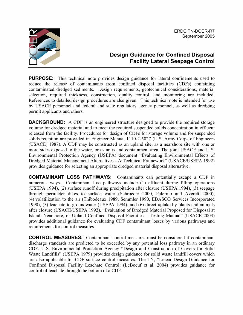
ERDC TN-DOER-R7 September 2005
Design Guidance for Confined Disposal Facility Lateral Seepage Control
PURPOSE: This technical note provides design guidance for lateral confinements used to reduce the release of contaminants from confined disposal facilities (CDFs) containing contaminated dredged sediments. Design requirements, geotechnical considerations, material selection, required thickness, construction, quality control, and monitoring are included. References to detailed design procedures are also given. This technical note is intended for use by USACE personnel and federal and state regulatory agency personnel, as well as dredging permit applicants and others. BACKGROUND: A CDF is an engineered structure designed to provide the required storage volume for dredged material and to meet the required suspended solids concentration in effluent released from the facility. Procedures for design of CDFs for storage volume and for suspended solids retention are provided in Engineer Manual 1110-2-5027 (U.S. Army Corps of Engineers (USACE) 1987). A CDF may be constructed as an upland site, as a nearshore site with one or more sides exposed to the water, or as an island containment area. The joint USACE and U.S. Environmental Protection Agency (USEPA) document “Evaluating Environmental Effects of Dredged Material Management Alternatives - A Technical Framework” (USACE/USEPA 1992) provides guidance for selecting an appropriate dredged material disposal alternative. CONTAMINANT LOSS PATHWAYS: Contaminants can potentially escape a CDF in numerous ways. Contaminant loss pathways include (1) effluent during filling operations (USEPA 1994), (2) surface runoff during precipitation after closure (USEPA 1994), (3) seepage through perimeter dikes to surface water (Schroeder 2000, Palermo and Averett 2000), (4) volatilization to the air (Thibodeaux 1989, Semmler 1990, EBASCO Services Incorporated 1990), (5) leachate to groundwater (USEPA 1994), and (6) direct uptake by plants and animals after closure (USACE/USEPA 1992). “Evaluation of Dredged Material Proposed for Disposal at Island, Nearshore, or Upland Confined Disposal Facilities – Testing Manual” (USACE 2003) provides additional guidance for evaluating CDF contaminant losses by various pathways and requirements for control measures. CONTROL MEASURES: Contaminant control measures must be considered if contaminant discharge standards are predicted to be exceeded by any potential loss pathway in an ordinary CDF. U.S. Environmental Protection Agency “Design and Construction of Covers for Solid Waste Landfills” (USEPA 1979) provides design guidance for solid waste landfill covers which are also applicable for CDF surface control measures. The TN, “Linear Design Guidance for Confined Disposal Facility Leachate Control: (LeBoeuf et al. 2004) provides guidance for control of leachate through the bottom of a CDF.
ERDC TN-DOER-R7 September 2005
DESIGN CONSIDERATIONS FOR LATERAL SEEPAGE CONTROL: This technical note includes discussion of design elements for lateral seepage control systems, including slurry walls and sheet-pile walls. All involve installation of a low-permeability core in the normal dike of a CDF. The information on slurry walls and sheet-pile walls is from "Design Guidance for Applications of Permeable Barriers to Remediate Dissolved Chlorinated Solvents," DG 1110-345-117 (USACE 1997). Detailed discussion of dike design and construction within which the aforementioned lateral control features may be employed is provided in USACE (1987). General Design Considerations. The purpose of a lateral seepage control system is to control leachate movement outside the boundaries of confined disposal facilities. The feasibility of implementing such control measures is predicated upon a review of the following items (after Spooner et al. (1985)): • Potential leachate incompatibility. • Anticipated hydraulic gradients and maximum allowable permeability in the completed
control feature. • Depth, permeability, continuity, and hardness of the aquiclude. • Wall placement relative to sediment and leachates. • Cost and time considerations. Each of these items is summarized in Table 1. Once determined necessary, design of such systems usually involves either a performance type specification or a materials and methods specification for contract execution. Table 2 summarizes various technologies for barrier wall emplacement. The following paragraphs provide additional design guidance specific to the particular control measure employed. In certain instances, it may be desirable or advantageous to control groundwater movement through other means such as trenches (passive) or groundwater pumping wells (active). These control features can effectively lower the groundwater table so that it will not intersect regions in which the contaminated sediment is placed. Example systems and design calculations are summarized in Canter and Knox (1985), among other sources. The effectiveness and long-term performance of a lateral seepage control system depends on the level of construction quality control that is implemented. National Seal Company (NSC) (1991), Cavalli (1992), and Sherman (1992) address the quality control issues involved with the liner and barrier technologies more commonly used in control measures for confined disposal facilities. Slurry Walls. Slurry walls are the most common subsurface barrier used for diverting or containing contaminated groundwater. They are constructed by first excavating a trench under a head of liquid slurry. The slurry, which is usually a mixture of bentonite and water, helps maintain the integrity of the trench by forming a filter cake over the face of the wall. As a trench is excavated, it is quickly refilled with a mixture of cement-bentonite or a selected soil-bentonite backfill. The more common slurry walls constructed are the soil-bentonite slurry wall and the cement-bentonite slurry wall. Another, but less common, type is the plastic concrete slurry wall. Several types of slurry walls are described in detail below.
2
ERDC TN-DOER-R7 September 2005
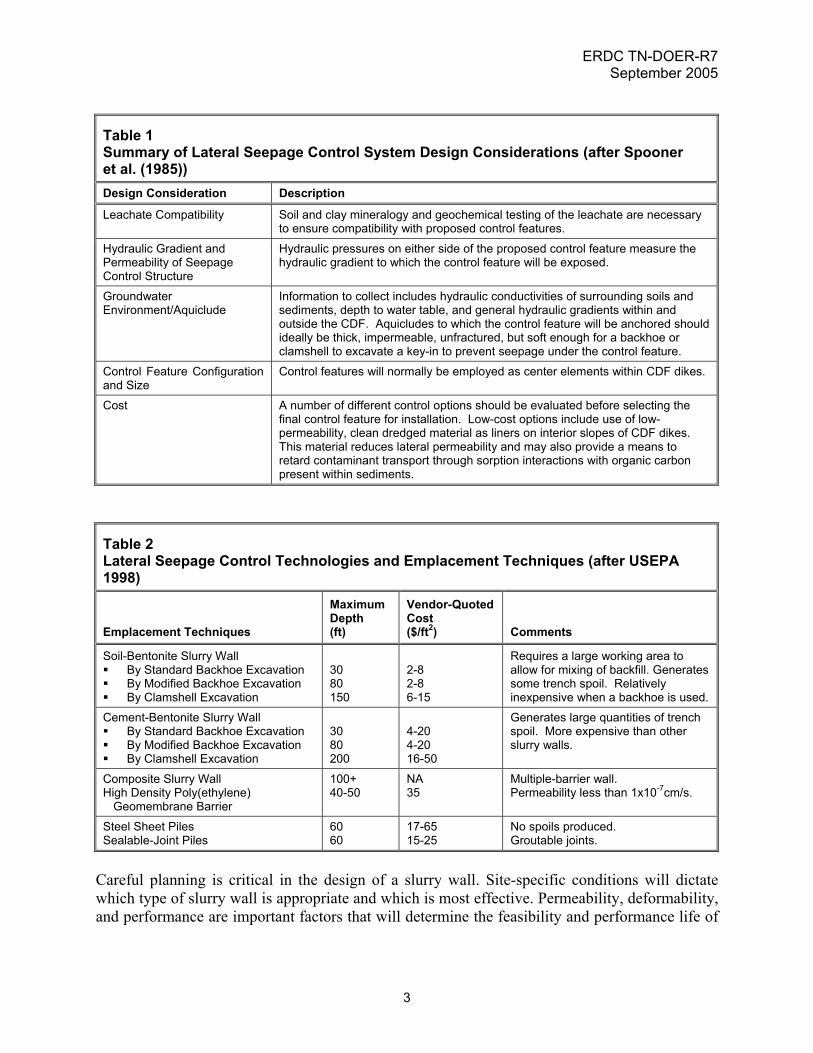
Table 1 Summary of Lateral Seepage Control System Design Considerations (after Spooner et al. (1985)) Design Consideration Description
Leachate Compatibility Soil and clay mineralogy and geochemical testing of the leachate are necessary to ensure compatibility with proposed control features.
Hydraulic Gradient and Permeability of Seepage Control Structure
Hydraulic pressures on either side of the proposed control feature measure the hydraulic gradient to which the control feature will be exposed.
Groundwater Environment/Aquiclude
Information to collect includes hydraulic conductivities of surrounding soils and sediments, depth to water table, and general hydraulic gradients within and outside the CDF. Aquicludes to which the control feature will be anchored should ideally be thick, impermeable, unfractured, but soft enough for a backhoe or clamshell to excavate a key-in to prevent seepage under the control feature.
Control Feature Configuration and Size
Control features will normally be employed as center elements within CDF dikes.
Cost A number of different control options should be evaluated before selecting the final control feature for installation. Low-cost options include use of low-permeability, clean dredged material as liners on interior slopes of CDF dikes. This material reduces lateral permeability and may also provide a means to retard contaminant transport through sorption interactions with organic carbon present within sediments.
Table 2 Lateral Seepage Control Technologies and Emplacement Techniques (after USEPA 1998)
Emplacement Techniques
Maximum Depth (ft)
Vendor-QuotedCost ($/ft2) Comments
Soil-Bentonite Slurry Wall By Standard Backhoe Excavation By Modified Backhoe Excavation By Clamshell Excavation
30 80 150
2-8 2-8 6-15
Requires a large working area to allow for mixing of backfill. Generates some trench spoil. Relatively inexpensive when a backhoe is used.
Cement-Bentonite Slurry Wall By Standard Backhoe Excavation By Modified Backhoe Excavation By Clamshell Excavation
30 80 200
4-20 4-20 16-50
Generates large quantities of trench spoil. More expensive than other slurry walls.
Composite Slurry Wall High Density Poly(ethylene)
Geomembrane Barrier
100+ 40-50
NA 35
Multiple-barrier wall. Permeability less than 1x10⁻⁷cm/s.
Steel Sheet Piles Sealable-Joint Piles
60 60
17-65 15-25
No spoils produced. Groutable joints.
Careful planning is critical in the design of a slurry wall. Site-specific conditions will dictate which type of slurry wall is appropriate and which is most effective. Permeability, deformability, and performance are important factors that will determine the feasibility and performance life of
3
ERDC TN-DOER-R7 September 2005
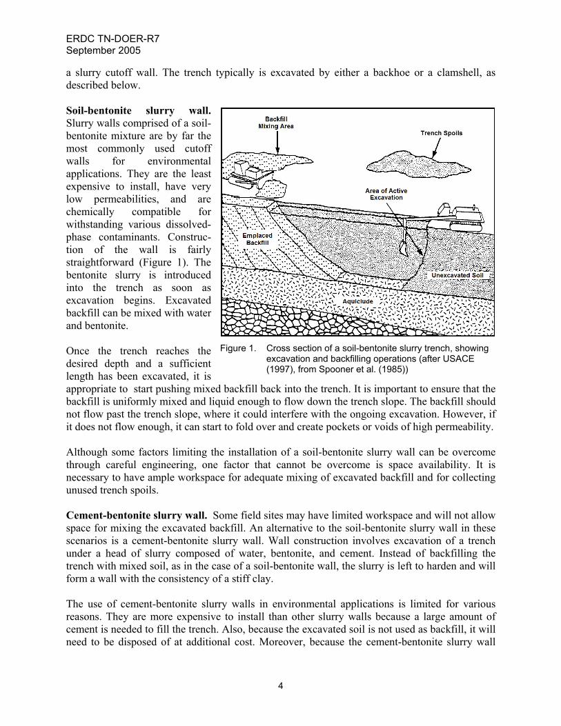
a slurry cutoff wall. The trench typically is excavated by either a backhoe or a clamshell, as described below. Soil-bentonite slurry wall. Slurry walls comprised of a soil-bentonite mixture are by far the most commonly used cutoff walls for environmental applications. They are the least expensive to install, have very low permeabilities, and are chemically compatible for withstanding various dissolved-phase contaminants. Construc-tion of the wall is fairly straightforward (Figure 1). The bentonite slurry is introduced into the trench as soon as excavation begins. Excavated backfill can be mixed with water and bentonite. Once the trench reaches the desired depth and a sufficient length has been excavated, it is appropriate to start pushing mixed backfill back into the trench. It is important to ensure that the backfill is uniformly mixed and liquid enough to flow down the trench slope. The backfill should not flow past the trench slope, where it could interfere with the ongoing excavation. However, if it does not flow enough, it can start to fold over and create pockets or voids of high permeability.
Figure 1. Cross section of a soil-bentonite slurry trench, showing excavation and backfilling operations (after USACE (1997), from Spooner et al. (1985))
Although some factors limiting the installation of a soil-bentonite slurry wall can be overcome through careful engineering, one factor that cannot be overcome is space availability. It is necessary to have ample workspace for adequate mixing of excavated backfill and for collecting unused trench spoils. Cement-bentonite slurry wall. Some field sites may have limited workspace and will not allow space for mixing the excavated backfill. An alternative to the soil-bentonite slurry wall in these scenarios is a cement-bentonite slurry wall. Wall construction involves excavation of a trench under a head of slurry composed of water, bentonite, and cement. Instead of backfilling the trench with mixed soil, as in the case of a soil-bentonite wall, the slurry is left to harden and will form a wall with the consistency of a stiff clay. The use of cement-bentonite slurry walls in environmental applications is limited for various reasons. They are more expensive to install than other slurry walls because a large amount of cement is needed to fill the trench. Also, because the excavated soil is not used as backfill, it will need to be disposed of at additional cost. Moreover, because the cement-bentonite slurry wall
4
ERDC TN-DOER-R7 September 2005
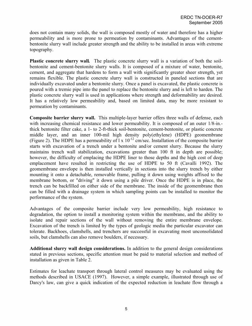
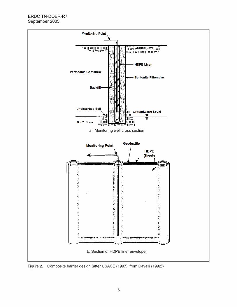
does not contain many solids, the wall is composed mostly of water and therefore has a higher permeability and is more prone to permeation by contaminants. Advantages of the cement-bentonite slurry wall include greater strength and the ability to be installed in areas with extreme topography. Plastic concrete slurry wall. The plastic concrete slurry wall is a variation of both the soil-bentonite and cement-bentonite slurry walls. It is composed of a mixture of water, bentonite, cement, and aggregate that hardens to form a wall with significantly greater sheer strength, yet remains flexible. The plastic concrete slurry wall is constructed in paneled sections that are individually excavated under a bentonite slurry. Once a panel is excavated, the plastic concrete is poured with a tremie pipe into the panel to replace the bentonite slurry and is left to harden. The plastic concrete slurry wall is used in applications where strength and deformability are desired. It has a relatively low permeability and, based on limited data, may be more resistant to permeation by contaminants. Composite barrier slurry wall. This multiple-layer barrier offers three walls of defense, each with increasing chemical resistance and lower permeability. It is composed of an outer 1/8-in.-thick bentonite filter cake, a 1- to 2-ft-thick soil-bentonite, cement-bentonite, or plastic concrete middle layer, and an inner 100-mil high density poly(ethylene) (HDPE) geomembrane (Figure 2). The HDPE has a permeability of l x 10-12 cm/sec. Installation of the composite barrier starts with excavation of a trench under a bentonite and/or cement slurry. Because the slurry maintains trench wall stabilization, excavations greater than 100 ft in depth are possible; however, the difficulty of emplacing the HDPE liner to those depths and the high cost of deep emplacement have resulted in restricting the use of HDPE to 50 ft (Cavalli 1992). The geomembrane envelope is then installed vertically in sections into the slurry trench by either mounting it onto a detachable, removable frame, pulling it down using weights affixed to the membrane bottom, or "driving" it down using a pile driver. Once the HDPE is in place, the trench can be backfilled on either side of the membrane. The inside of the geomembrane then can be filled with a drainage system in which sampling points can be installed to monitor the performance of the system. Advantages of the composite barrier include very low permeability, high resistance to degradation, the option to install a monitoring system within the membrane, and the ability to isolate and repair sections of the wall without removing the entire membrane envelope. Excavation of the trench is limited by the types of geologic media the particular excavator can tolerate. Backhoes, clamshells, and trenchers are successful in excavating most unconsolidated soils, but clamshells can also remove boulders, if necessary. Additional slurry wall design considerations. In addition to the general design considerations stated in previous sections, specific attention must be paid to material selection and method of installation as given in Table 2. Estimates for leachate transport through lateral control measures may be evaluated using the methods described in USACE (1997). However, a simple example, illustrated through use of Darcy's law, can give a quick indication of the expected reduction in leachate flow through a
5
ERDC TN-DOER-R7 September 2005
a. Monitoring well cross section
b. Section of HDPE liner envelope
Figure 2. Composite barrier design (after USACE (1997), from Cavalli (1992))
6
ERDC TN-DOER-R7 September 2005
slurry wall. Using hypothetical site dimensions of a slurry wall 50 m long, 25 m deep, and 1 m thick, and Darcy's law (Spooner et al. 1985):
Q = AKdh
dl
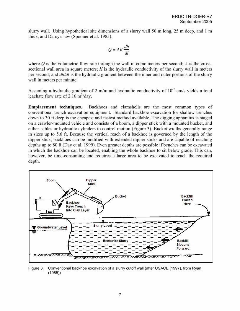
where Q is the volumetric flow rate through the wall in cubic meters per second; A is the cross-sectional wall area in square meters; K is the hydraulic conductivity of the slurry wall in meters per second; and dh/dl is the hydraulic gradient between the inner and outer portions of the slurry wall in meters per minute. Assuming a hydraulic gradient of 2 m/m and hydraulic conductivity of 10-7 cm/s yields a total leachate flow rate of 2.16 m3/day. Emplacement techniques. Backhoes and clamshells are the most common types of conventional trench excavation equipment. Standard backhoe excavation for shallow trenches down to 30 ft deep is the cheapest and fastest method available. The digging apparatus is staged on a crawler-mounted vehicle and consists of a boom, a dipper stick with a mounted bucket, and either cables or hydraulic cylinders to control motion (Figure 3). Bucket widths generally range in sizes up to 5.6 ft. Because the vertical reach of a backhoe is governed by the length of the dipper stick, backhoes can be modified with extended dipper sticks and are capable of reaching depths up to 80 ft (Day et al. 1999). Even greater depths are possible if benches can be excavated in which the backhoe can be located, enabling the whole backhoe to sit below grade. This can, however, be time-consuming and requires a large area to be excavated to reach the required depth.
Figure 3. Conventional backhoe excavation of a slurry cutoff wall (after USACE (1997), from Ryan
(1985))
7
ERDC TN-DOER-R7 September 2005
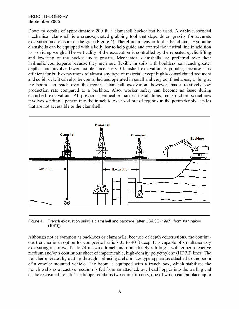
Down to depths of approximately 200 ft, a clamshell bucket can be used. A cable-suspended mechanical clamshell is a crane-operated grabbing tool that depends on gravity for accurate excavation and closure of the grab (Figure 4). Therefore, a heavier tool is beneficial. Hydraulic clamshells can be equipped with a kelly bar to help guide and control the vertical line in addition to providing weight. The verticality of the excavation is controlled by the repeated cyclic lifting and lowering of the bucket under gravity. Mechanical clamshells are preferred over their hydraulic counterparts because they are more flexible in soils with boulders, can reach greater depths, and involve fewer maintenance costs. Clamshell excavation is popular, because it is efficient for bulk excavations of almost any type of material except highly consolidated sediment and solid rock. It can also be controlled and operated in small and very confined areas, as long as the boom can reach over the trench. Clamshell excavation, however, has a relatively low production rate compared to a backhoe. Also, worker safety can become an issue during clamshell excavation. At previous permeable barrier installations, construction sometimes involves sending a person into the trench to clear soil out of regions in the perimeter sheet piles that are not accessible to the clamshell.
Figure 4. Trench excavation using a clamshell and backhoe (after USACE (1997), from Xanthakos
(1979)) Although not as common as backhoes or clamshells, because of depth constrictions, the continu-ous trencher is an option for composite barriers 35 to 40 ft deep. It is capable of simultaneously excavating a narrow, 12- to 24-in.-wide trench and immediately refilling it with either a reactive medium and/or a continuous sheet of impermeable, high-density polyethylene (HDPE) liner. The trencher operates by cutting through soil using a chain-saw type apparatus attached to the boom of a crawler-mounted vehicle. The boom is equipped with a trench box, which stabilizes the trench walls as a reactive medium is fed from an attached, overhead hopper into the trailing end of the excavated trench. The hopper contains two compartments, one of which can emplace up to
8
ERDC TN-DOER-R7 September 2005
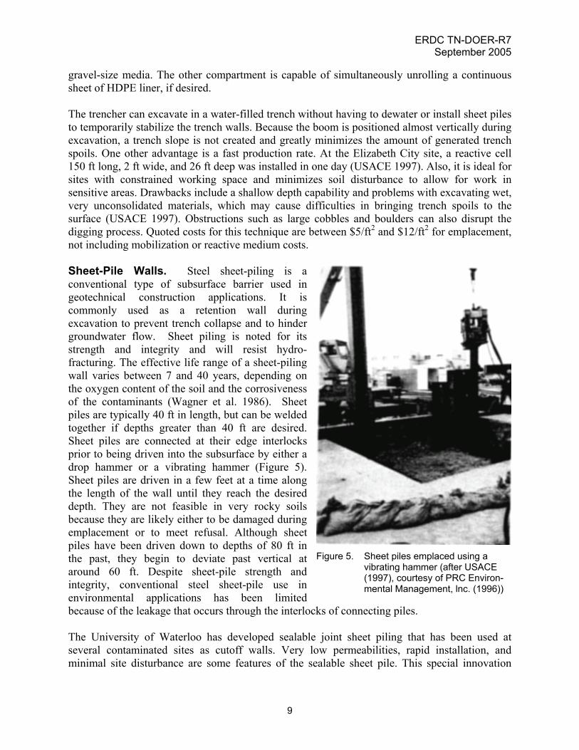
gravel-size media. The other compartment is capable of simultaneously unrolling a continuous sheet of HDPE liner, if desired. The trencher can excavate in a water-filled trench without having to dewater or install sheet piles to temporarily stabilize the trench walls. Because the boom is positioned almost vertically during excavation, a trench slope is not created and greatly minimizes the amount of generated trench spoils. One other advantage is a fast production rate. At the Elizabeth City site, a reactive cell 150 ft long, 2 ft wide, and 26 ft deep was installed in one day (USACE 1997). Also, it is ideal for sites with constrained working space and minimizes soil disturbance to allow for work in sensitive areas. Drawbacks include a shallow depth capability and problems with excavating wet, very unconsolidated materials, which may cause difficulties in bringing trench spoils to the surface (USACE 1997). Obstructions such as large cobbles and boulders can also disrupt the digging process. Quoted costs for this technique are between $5/ft2 and $12/ft2 for emplacement, not including mobilization or reactive medium costs. Sheet-Pile Walls. Steel sheet-piling is a conventional type of subsurface barrier used in geotechnical construction applications. It is commonly used as a retention wall during excavation to prevent trench collapse and to hinder groundwater flow. Sheet piling is noted for its strength and integrity and will resist hydro-fracturing. The effective life range of a sheet-piling wall varies between 7 and 40 years, depending on the oxygen content of the soil and the corrosiveness of the contaminants (Wagner et al. 1986). Sheet piles are typically 40 ft in length, but can be welded together if depths greater than 40 ft are desired. Sheet piles are connected at their edge interlocks prior to being driven into the subsurface by either a drop hammer or a vibrating hammer (Figure 5). Sheet piles are driven in a few feet at a time along the length of the wall until they reach the desired depth. They are not feasible in very rocky soils because they are likely either to be damaged during emplacement or to meet refusal. Although sheet piles have been driven down to depths of 80 ft in the past, they begin to deviate past vertical at around 60 ft. Despite sheet-pile strength and integrity, conventional steel sheet-pile use in environmental applications has been limited because of the leakage that occurs through the interlocks of connecting piles.
Figure 5. Sheet piles emplaced using a vibrating hammer (after USACE (1997), courtesy of PRC Environ-mental Management, lnc. (1996))
The University of Waterloo has developed sealable joint sheet piling that has been used at several contaminated sites as cutoff walls. Very low permeabilities, rapid installation, and minimal site disturbance are some features of the sealable sheet pile. This special innovation
9
ERDC TN-DOER-R7 September 2005
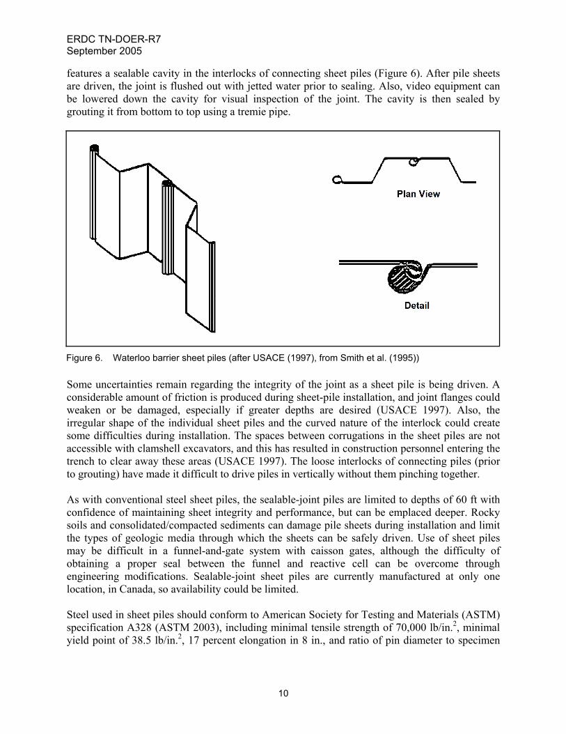
features a sealable cavity in the interlocks of connecting sheet piles (Figure 6). After pile sheets are driven, the joint is flushed out with jetted water prior to sealing. Also, video equipment can be lowered down the cavity for visual inspection of the joint. The cavity is then sealed by grouting it from bottom to top using a tremie pipe.
Figure 6. Waterloo barrier sheet piles (after USACE (1997), from Smith et al. (1995)) Some uncertainties remain regarding the integrity of the joint as a sheet pile is being driven. A considerable amount of friction is produced during sheet-pile installation, and joint flanges could weaken or be damaged, especially if greater depths are desired (USACE 1997). Also, the irregular shape of the individual sheet piles and the curved nature of the interlock could create some difficulties during installation. The spaces between corrugations in the sheet piles are not accessible with clamshell excavators, and this has resulted in construction personnel entering the trench to clear away these areas (USACE 1997). The loose interlocks of connecting piles (prior to grouting) have made it difficult to drive piles in vertically without them pinching together. As with conventional steel sheet piles, the sealable-joint piles are limited to depths of 60 ft with confidence of maintaining sheet integrity and performance, but can be emplaced deeper. Rocky soils and consolidated/compacted sediments can damage pile sheets during installation and limit the types of geologic media through which the sheets can be safely driven. Use of sheet piles may be difficult in a funnel-and-gate system with caisson gates, although the difficulty of obtaining a proper seal between the funnel and reactive cell can be overcome through engineering modifications. Sealable-joint sheet piles are currently manufactured at only one location, in Canada, so availability could be limited. Steel used in sheet piles should conform to American Society for Testing and Materials (ASTM) specification A328 (ASTM 2003), including minimal tensile strength of 70,000 lb/in.2, minimal yield point of 38.5 lb/in.2, 17 percent elongation in 8 in., and ratio of pin diameter to specimen
10
ERDC TN-DOER-R7 September 2005
11
diameter of 2 for the 180-deg bend test. (Grout used in sealable-joint sheet piles is described in the following sections on grout use in permeable reactive barrier design.) SUMMARY: This technical note presents technical guidance for designing confined disposal facility lateral seepage control systems to enhance containment of pollutants. The guidance is summarized in the points below. • CDF lateral seepage control systems that isolate the contaminated material from the
environment must be properly designed, constructed, and maintained.
• System materials must be characterized from the physical, chemical, and biological standpoints. Determining the minimum required lateral seepage control system thickness is dependent on the physical and chemical properties of the contaminated sediments and the seepage control materials, including the potential for consolidation.
• Scheduling of lateral seepage control system construction must consider both exposure of the system materials to the environment and engineering and operational constraints.
POINTS OF CONTACT: For additional information, contact Dr. Paul R. Schroeder (601-634-3709, [email protected]) or the manager of the Dredging Operations and Environmental Research Program, Dr. Robert M. Engler (601-634-3624, Robert.M.Engler@ erdc.usace.army.mil). This technical note should be cited as follows:
LeBoeuf, E. J., and Thackston, E. L. (2005). “Design guidance for confined disposal facility lateral seepage control,” DOER Technical Notes Collection (ERDC TN-DOER-R7), U.S. Army Engineer Research and Development Center, Vicksburg, MS. http://el.erdc.usace.army.mil/dots/doer/
REFERENCES American Society for Testing and Materials (ASTM). (2003). “Standard specification for steel sheet piling,”
ASTM A328/A328M-03, West Conshohocken, PA.
Canter, L. W., and Knox, R. C. (1985). Groundwater pollution control. Lewis Publishers, Inc., Chelsea, MI.
Cavalli, N. J. (1992). “Composite barrier slurry wall.” Slurry walls: Design, construction and quality control. ASTM/STP 1129, Paul, D. B., Davidson, R. R., and Cavalli, N. J. (ed.), American Society for Testing and Materials, West Conshohocken, PA.
Day, S. R., O’Hannesin, S. F., and Marsden, L. (1999). “Geotechnical techniques for the construction of reactive barriers,” Journal of Hazardous Materials 67(3), 285-297.
EBASCO Services Incorporated. (1990). “Final air monitoring report volume I, New Bedford Harbor pilot dredging and disposal study,” Contractor Report for EPA Contract Number 68-01-7250.
LeBoeuf, E. J., Thackston, E. L., Schroeder, P. R., and Palermo, M. R. (2004). “ Liner design guidance for confined disposal facility leachate control,” DOER Technical Notes Collection (ERDC TN-DOER-R6), U.S. Army Engineer Research and Development Center, Vicksburg, MS. http://el.erdc.usace.army.mil/dots/doer/
National Seal Company (NSC). (1991). Construction quality control manual. National Seal Company, Aurora, IL.
Palermo, M. R., and Averett, D. E. (2000). “Confined disposal facility (CDF) containment features: A summary of field experience,” DOER Technical Notes Collection (ERDC TN DOER-C18), U.S. Army Engineer Research and Development Center, Vicksburg, MS. http://el.erdc.usace.army.mil/dots/doer/
ERDC TN-DOER-R7 September 2005
PRC Environmental Management, Inc. (1996). Naval Air Station Moffett Field, California, Iron Curtain Area Groundwater Flow Model. PRC, June.
Ryan, C. R. (1985). “Slurry cutoff walls: Applications in the control of hazardous wastes.” Hydraulic barriers in soil and rock. ASTM STP 874, Johnson, A. I., Frobel, R. K., Cavalli, N. J. and Peterson, C. B. (ed.), American Society for Testing and Materials, West Conshohocken, PA.
Schroeder, P. R. (2000). “Leachate screening considerations,” DOER Technical Notes Collection (ERDC TN DOER-C16), U.S. Army Engineer Research and Development Center, Vicksburg, MS. http://el.erdc.usace.army.mil/dots/doer/
Semmler, J. A. (1990). “PCB-volatilization from dredged material, Indiana Harbor, IN,” Environmental Effects of Dredging Technical Notes, EEDP-02-12, U.S. Army Engineer Waterways Experiment Station, Vicksburg, MS.
Sherman, V. W. (1992). Construction quality control and construction quality assurance for low permeability clay barrier soils. Michigan Department of Natural Resources, Lansing, MI.
Smith, D., Cherry, J., and Jowett, R. (1995). “Sealable joint steel sheet piling for groundwater pollution control.” Proceedings of ER ’95: Committed to Results, U.S. Department of Energy, Denver, CO.
Spooner, P., Wetzel, R., Spooner, C., Furman, C., Tokarski, E., Hunt, G., Hodge, V., and Robinson, T. (1985). Slurry trench construction for pollution migration control. Noyes Publications, Park Ridge, NJ.
Thibodeaux, L. J. (1989). “Theoretical models for evaluation of volatile emissions to air during dredged material disposal with applications to New Bedford Harbor, Massachusetts,” Miscellaneous Paper EL-89-3, U.S. Army Engineer Waterways Experiment Station, Vicksburg, MS.
U.S. Army Corps of Engineers (USACE). (1987). “Confined disposal of dredged material,” Engineer Manual 1110-2-5027, Office, Chief of Engineers, Washington, DC.
______. (1997). “Design guidance for applications of permeable barriers to remediate dissolved chlorinated solvents,” USACE DG 1110-345-117, Office, Chief of Engineers, Washington, DC.
______. (2003). “Evaluation of dredged material proposed for disposal at island, nearshore, or upland confined disposal facilities – Testing manual,” Technical Report ERDC/EL TR-03-1, U.S. Army Engineer Research and Development Center, Vicksburg, MS.
U.S. Army Corps of Engineers (USACE)/U.S. Environmental Protection Agency (USEPA). (1992). “Evaluating environmental effects of dredged material management alternatives - A technical framework,” EPA842-B-92-008, U.S. Army Corps of Engineers and U.S. Environmental Protection Agency, Washington, DC.
U.S. Environmental Protection Agency (USEPA). (1979). “Design and construction of covers for solid waste landfills,” EPA 600/2-79/165, U.S. Environmental Protection Agency, Washington, DC.
______. (1994). “Assessment and remediation of contaminated sediments (ARCS) program: Remediation guidance document,” EPA 905-B94-003, U.S. Environmental Protection Agency, Washington, DC.
______. (1998). "Permeable reactive barrier technologies for contaminant remediation," EPA/600/R-98/125, U.S. Environmental Protection Agency, Washington, DC.
Wagner, K., Boyer, K., Claff, R., Evans, M., Henry, S., Hodge, V., Mahmud, S., Sarno, D., Scopino, E., and Pooner, P. (1986). Remedial action technology for waste disposal sites. Noyes Data Corporation, Park Ridge, NJ.
Xanthakos, P. P. (1979). Slurry walls. McGraw-Hill Book Co., NY.
NOTE: The contents of this technical note are not to be used for advertising, publication, or promotional purposes. Citation of trade names does not constitute an official endorsement or approval of the use of such products.
12