Embed Size (px)
Citation preview

FACULTY OF ENGINEERING AND SUSTAINABLE DEVELOPMENT Department of Building, Energy and Environmental Engineering
Environmental Assessment of a Residential Building According to Miljö byggnad
Ning Li
2015
Student thesis, Bachelor degree, 15 HE Energy Technology
Study Programme in Energy Systems Engineering
Degree Project for a Bachelor of Science with Major in Energy Systems
Supervisor: Peter Hansson Examiner: Mathias Cehlin


Abstract
Miljöbyggnad is a Swedish system for certifying building in regarding to energy, indoor
climate and materials. Energy usage in built environment occupies more than a third of
total energy consumption and greenhouse gas emissions in Sweden (SEA, 2008).
Among fifteen indicators regulated by Miljöbyggnad, four indicators which consist of
specific energy use, thermal climate winter, thermal climate summer and daylight have
been analyzed in this report.
There has two objectives for the project. The first objective is to make optimized
approaches for the building according to baseline simulation model. And the second
objective is to make assessment of the optimized model based on Miljöbyggnad
environmental certification.
As a conclusion, the implemented approaches helped to improve indoor thermal comfort
and decrease demand of operational electricity for lighting. The four analyzed indicator
of the optimized model have achieved GOLD level according to criteria regulated by
Miljöbyggnad.

Table of Contents
Abstract ........................................................................................................................... III
1. Introduction .............................................................................................................. 1 Background ................................................................................................................... 1 Objective ....................................................................................................................... 3 Method .......................................................................................................................... 4
2. Setup of Baseline Model............................................................................................... 5
Geometry ...................................................................................................................... 5 Building Envelope ........................................................................................................ 5
3. Energy performance of the baseline model .................................................................. 7
Energy Demand ............................................................................................................ 7 Heating ..................................................................................................................... 8 Ventilation ................................................................................................................ 9 Lighting .................................................................................................................... 9
Occupant and Equipment.......................................................................................... 9
4. Optimization and Assessment based on Miljöbyggnad .............................................. 10 Measure proposal ........................................................................................................ 10 Indicator 1: Specific energy use ................................................................................. 10
Criteria .................................................................................................................... 10
Assessment ............................................................................................................. 10 Indicator 10: Thermal climate winter ......................................................................... 12
Criteria .................................................................................................................... 12
Assessment ............................................................................................................. 12
Indicator 11: Thermal climate summer ...................................................................... 14 Criteria .................................................................................................................... 14
Assessment ............................................................................................................. 14 Indicator 12: Daylight ................................................................................................. 15
Criteria .................................................................................................................... 15
Assessment ............................................................................................................. 15
5. Discussion of additional measures ............................................................................. 18
Ventilation system ...................................................................................................... 18 Lighting Control ......................................................................................................... 18
6. Conclusion .................................................................................................................. 20
References ...................................................................................................................... 21
Appendix I – Energy Performance (the First Floor)....................................................... 22
Appendix II – Energy Performance (the Second Floor) ................................................. 23
Appendix III – Energy Performance (the Third Floor) .................................................. 24
Appendix IV – Energy Performance (the Fourth Floor) ................................................ 25
Appendix V – Energy Performance (the Fifth Floor)..................................................... 26
Appendix VI – Daylight intensity of Zone 5 in Lux ...................................................... 27
Appendix VII – Comfort indices of Zone 5. .................................................................. 28

1
1. Introduction
Background
In developed countries, energy consumption by building is occupied around 30% - 40%
of total energy use. As stated by Asdrubali and et al. (Asdrubali, et al., 2015), with growth
of urbanization, population and demand of building comfort and services, building energy
efficiency is significantly demand to be improved. Meanwhile, cost of energy and
environmental impact are also the important objectives for building’s sustainability
(Andaloro, et al., 2010). Based on such expectations, concept of green building is firstly
launched and operated by the Building Research Establishment (BRE) in 1988 and the
assessment tool is named BREEAM (Building Research Establishment Environmental
Assessment Method) as described by Lee and Burnett (Lee & Burnett, 2007). Today, over
250 000 buildings are certificated by BREEAM. LEED (Leadership in Energy and
Environmental Design) is a more widely applied building environmental assessment tool
now day (Seinre, et al., 2014) which developed by U.S. Green Building Council and
implemented over 24 countries.
Miljöbyggnad is a Swedish system for certifying building in regarding to energy, indoor
climate and materials. Energy usage in built environment occupies more than a third of
total energy consumption and greenhouse gas emissions in Sweden (SEA, 2008). As
stated by Sweden’s national goals, energy usage in the building sector is to be reduced by
20% till 2020 and 50% till 2050 (Molin, et al., 2011). Indoor climate of residential
building is a significant factor for influencing thermal comfort of dwellers. During
procedure of Miljöbyggnad certifying, credits given by indoor environment performance
is around 60% of the total credits which represents the main portion of building energy
and environmental performance.
Figure 1, Aggregation tool of Miljöbyggnad certification for new building.
There are three degrees of the certification, ranked from lowest to highest performance
as BRONZE, SILVER and GOLD. In order to evaluate the degree of the certification for

2
the building, an aggregation tool provided by SGBC (SGBC, 2014) will be employed.
According to manual regulated by SGBC (SGBC, 2014), fifteen indicators which belong
to the three main areas are required to be illustrated. However, four indicators from the
fifteens will be discussed and analyzed in this project. Which are energy use, thermal
climate winter, thermal climate summer and daylight. As shown in Figure 1, explanation
of the rest indicators which required to be achieved to the GOLD degree are also briefly
discussed and presented based on simulation results of the building.

3
Objective
Two main objectives of the project has been set up.
The first objective is to build optimized approaches for the baseline simulation model of
the building in order to achieve GOLD for Miljöbyggnad certification.
The second objective is to make assessment for indicator 1 specific energy use, indicator
10 thermal climate winter, indicator 11 thermal climate summer and indicator 12 daylight.
To verify if the four indicators can achieve gold level.

4
Method
Building energy performance simulation through the simulation code IDA ICE (Indoor
climate and Energy) is the main approach for assessment of Miljöbyggnad criteria in this
project. With simulated results of building energy demand, indoor thermal comfort
indices and indoor air quality level, controlling of lower energy consumption, better
energy performance and more comfortable indoor climate can be designed and achieved.
For assessment of indicator 12 daylight, simulation code Ecotect Analysis and VELUX
Daylight Visualizer are also employed for expressing surrounding sunlight path and
indoor daylight factor of the building.
In order to decide adaptable simulation model of the building, literature review from
relative scientific papers and corresponding international standards was applied during
setup of both baseline and optimized model.

5
2. Setup of Baseline Model
The investigated building in this project is built for residential purpose and located in
Gävle, Sweden. Due to the limitation of the simulation code IDA ICE, climate data of the
location is set as weather condition of Stockholm according to ASHRAE weather data
instead, which has a similarity climate profile. There is no holiday required to be specified
for the building.
Geometry Geometry of the building for the baseline model is constructed as shown in Figure 2.
(a) (b)
(c) (d)
Figure 2, Geometry of the investigated building.
The residential building contains five floors. Within the domain of the building, four types
of zones have been separated and drawn. Which are apartments, elevator, staircase and
common areas. The common areas include corridor, laundry room and mechanic rooms
on the top floor.
Computed from IDA ICE, the total floor area of the building is around 2503m2 and the
total area of windows is around 208.63m2 for baseline model.
Building Envelope
As described by Dr. Lal Jayamaha (Jayamaha, 2006), the building envelope plays a key
role for regulating indoor environment which is significantly influence heating,

6
ventilation and air-conditioning systems of the designated building. Walls, roofs, floors,
windows and doors are the main components of building envelope. Heat gain and loss
through the building envelope is by conduction, convection and radiation. Air leakage are
also required to be considered during the building energy simulation.
According to building code regulated by BBR (Boverket’s building regulation), the air
tight of building envelope shall be sufficiently that at 50 Pa pressure different between
interior and exterior, the average air leakage does not exceed 0.6 l/s-m2. From supplied
data, the building has achieved 0.3 l/s-m2 of average air leakage. With multiplied by areas
of building envelope, the maximum total air leakage of the building is 804.474 l/s at 50
Pa as shown in Table 1.
Table 1, Input data of building envelope.
To analysis of complex building envelope material, the concept of thermal resistance (R-
value) is usually to be used for describing each component. However, McQuiston and et
al. (McQuiston, et al., 2005) mentioned that the overall heat transfer coefficient (U-value)
is more frequently and conveniently to be implemented.
U value of each building component can be expressed as (McQuiston, et al., 2005):
'
1 1=U
R A R (Equation 1)
Heat transfer rate through each component can be expressed as:
Q UA t (Equation 2)
As listed in Table 1, U values of external walls, windows and doors are set as 0.11, 0.92
and 1W/K-m2 which is defined according to the given data and lower than BBR
regulations.
As definite by McQuiston and et al. (McQuiston, et al., 2005), a large variation in the
thermal resistance of the building envelope is named thermal bridge. Compared with the
contiguous parts of the building envelope, thermal bridges are the areas which have a
significantly higher rate of heat transfer. Due to its’ influence to building envelope’s heat
insulation performance, thermal bridges are required to be set before the simulation. In
this project, typical level of thermal bridge of the building envelope was selected.

7
3. Energy performance of the baseline model
Energy Demand According to the Swedish Legislation (BBR 20), building energy performance consist of
three main parts which include building electricity, heating system and comfort cooling,
meanwhile the operational electricity does not taken into consideration to the total
building energy usage, but it still influence the building energy balance. As described by
Swedish Legislation (BFS, 2011), the building needs for cooling shall be minimized. The
general recommendation states instead of installation of cooling system, choose other
measures such as sun-shading and reduce internal heat loads through electrical lighting
or equipments (BFS, 2011).
Energy demand of the building are computed and presented in Table 2. The total energy
demand for the building of the baseline model is 46.8 kWh/m2, which includes 28.9
kWh/m2 of district heating, 8.8 kWh/m2 of electricity for lighting and 9 kWh/m2 of HVAC
auxiliary. The total electricity for tenant (household electricity) is 30 kWh/m2 (SVEBY,
2012) which consist of 10.5 kWh/m2 of electrical lighting for apartments and 19.5
kWh/m2 of equipment electricity.
Table 2,Energy Demand for the baseline model.
Delivered energy Demand
kWh kWh/m2 kW
Lighting, facility 22229 8.8 3.19
HVAC aux 22778 9.0 2.64
Total, Facility electric 45007 17.9
District cooling 0 0.0 0.0
District heating 73003 28.9 37.9
Total, Facility district 73003 28.9
Total 118010 46.8
Lighting, tenant 26433 10.5 9.95
Equipment, tenant 49185 19.5 9.62
Total, Tenant electric 75618 30.0
Grand total 193628 76.8
Monthly delivered energy for the baseline model is shown as in Figure 3. Each color is
represented different energy demand sector as list in Table 2.Figure 2
Figure 3, Monthly delivered energy for the baseline model.
Month 1 2 3 4 5 6 7 8 9 10 11 12
kWh
0·0 3
2·0ʴ3
4·0ҁ3
6·0Ҁ3
8·0Ҁ3
10·0嘀3
12·0弄3
14·0殱3
16·0搀3
18·0縀3

8
As shown in Figure 3, the maximum heating demand is in December and January. Due
to control method of operational lighting and ventilation system for the baseline model,
demands of electricity for operational lighting and ventilation are constant throughout the
year.
Heating
The building is connected to a district heating system, which supplies heat to the radiators
for space heating. The coefficient of performance (COP) of heating is 0.98. The air
handing units (AHUs) to conditioning the incoming ventilation air, and for the hot tap
water.
The supplied air to the building has to be heated to 16oC. According to statistics by
SVEBY (SVEBY, 2012), the indoor air temperature set point for heating is 21oC.
Changings of AHUs temperatures for baseline model are presented as in Figure 4. As
shown as blue line in the figure, the return air temperature is operated between 21.5 oC to
31.1 oC. However, the comfort indoor temperature range of Swedish residential building
is between 21 oC to 26 oC. With no substitutable measures for comfort cooling of baseline
model, the percentage of total occupant hours with thermal dissatisfied (PPD) is 30%.
The hot tap water needs to be heated and stored in tanks at temperatures between 55 oC
to 65 oC and the heat is distributed by several radiators in the building. SVEBY illustrated
that the year standard of hot tap water for residential building is 25 kWh/m2.
Figure 4, AHUs temperatures changing.
Heat recovery efficiency of the air handing unit is 85%. As shown in Figure 4, return air
temperature is higher than the temperature of supply air. For recovery waste heat from air
outlet, heat exchangers are required to be installed.
Figure 5, Monthly energy usage of AHUs.
Return air dry-bulb temperature, Deg-C
Supply air dry-bulb temperature, Deg-C
Outside air dry-bulb temperature, Deg-C
0 1000 2000 3000 4000 5000 6000 7000 8000
Jan Feb Mar Apr May Jun Jul Aug Sep Oct Nov Dec
癈
-15
-10
-5
0
5
10
15
20
25
30
Entire simulation: from 2014/1/1 to 2014/12/31
Month 1 2 3 4 5 6 7 8 9 10 11 12
kWh
0·0ȏ3
2·03
ؽ0·43
6·0ȏ3
8·0Ӆ3
10·03
12·0뀀3
14·0롰3
16·0 3
9
As shown in Figure 5, pink bars indicated AHUs heat recovery. The annual heat recovery
for baseline model is 91720.5 kWh.
Ventilation
Ventilation system for baseline model is a constant air volume system. With the minimum
supply air flow rate equals to 0.35l/s per m2 as regulated by BBR20. Beside heat recovery
efficiency, specific fan power (SFP) is another important factor for influencing energy
demand of ventilation system. The SFP value of fans for the AHUs is expressed as
Equation 3 (Engdahl & Johansson, 2003).
=P
SFPqv
(Equation 3)
Where, P is total fan power (kW), qv is amount air flow through the fan (m3/s).
Which means with a lower SFP value, power demand of fans is lower for supplement of
equivalent air. The SFP value of the building AHUs is 1.5.
The contaminant concentration level of indoor environment has to be controlled. With
installed sensor, carbon dioxide concentration is required to be controlled between 0 ppm
to 800ppm according to ASHRAE standards.
Lighting
Electric lighting expenditures assumed as keep in constant throughout the year for
baseline model. As described by Dr. Lal Jayamaha (Jayamaha, 2006), the lighting power
density can be used for evaluating the overall efficiency of a lighting design. ASHRAE
Standard prescribes that a simplest method for determination of interior lighting power is
determine the maximum allowable lighting power density in W/m2, with multiplied by
the lighted floor areas, the gross demand of lighting power can be computed.
According to recommended range given by ASHRAE standard, 6 W/m2 of lighting power
density is set for apartments and 3 W/m2 of lighting power density for common areas such
as corridors, elevators and staircases. Compact fluorescent lamp is the usual type of lamp.
Therefore, 55 lm/W of luminous efficacy is implemented in the baseline model.
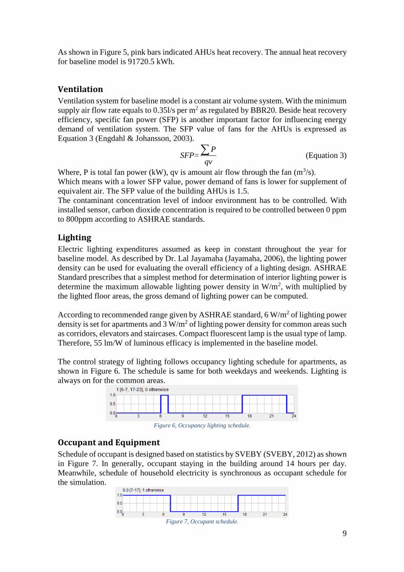
The control strategy of lighting follows occupancy lighting schedule for apartments, as
shown in Figure 6. The schedule is same for both weekdays and weekends. Lighting is
always on for the common areas.
Figure 6, Occupancy lighting schedule.
Occupant and Equipment
Schedule of occupant is designed based on statistics by SVEBY (SVEBY, 2012) as shown
in Figure 7. In generally, occupant staying in the building around 14 hours per day.
Meanwhile, schedule of household electricity is synchronous as occupant schedule for
the simulation.
Figure 7, Occupant schedule.

10
4. Optimization and Assessment based on Miljöbyggnad
Measure proposal During this project, some improved measures upon the baseline model of the building
should be implemented in the simulation for achieving a better certification level.
For indicator 7 Ventilation standard of Miljöbyggnad, type of ventilation system
is changed from CAV to VAV system with temperature control.
For indicator 11, due to with no cooling system installed, indoor air temperature
in summer is much higher than standard of comfort temperature. Blinds between
window’s panes will be installed for add shielding to the windows in order to
reduce overheating during summer. VAV system instead of CAV system with
minimum constant supply air flow rate also contributed to improve indoor thermal
comfort of the building.
For indicator 12 Daylight, in order to achieve the required window to floor area
ratio (AF), total areas of window is increased. Meanwhile, combination between
lighting system with daylight through the windows, artificial lighting control upon
daylight intensity is implemented by installation of daylight sensor.
In the following sections, detailed measures and assessments regarding indicator 1, 10,
11 and 12 of Miljöbyggnad according to the optimized model will be analyzed and
discussed.
Indicator 1: Specific energy use
Criteria
The assessment criteria for dwellings and non-residential premises with heating method
other than electric heating is shown in Table 3.
Table 3, Assessment criteria for indicator 1: Specific energy use.
Assessment
According to regulation by BBR, Gävleborg is belonging to Climate zone 2. The
building’s specific energy use for dwelling in Climate zone 2 is 110 kWh/m2 Atemp per
year. Therefore, in order to achieve gold level, specific energy use of the optimized model
for the building should be lower than 71.5 kWh/m2 Atemp per year.
Delivery energy overview from simulation result of the optimized model is listed in Table
4. It can be seen the specific energy use of the building is 52.4 kWh/m2 per year. Therefore,
gold level of indicator 1 can be achieved.
Energy Performance of each floor of the building for the optimized model are listed in
Appendix I to Appendix V.

11
Table 4, Delivered energy overview of the optimized model.
Delivered energy Demand
kWh kWh/m2 kW
Lighting, facility 20048 8.0 3.19
HVAC aux 32315 12.8 52.71
Total, Facility electric 52363 20.8
District cooling 0 0.0 0.0
District heating 79675 31.6 42.6
Total, Facility district 79675 31.6
Total 132038 52.4
Lighting, tenant 23043 9.1 9.95
Equipment, tenant 49190 19.5 9.62
Total, Tenant electric 72233 28.6
Grand total 204271 81.0
Items of the specific energy use required to be identified as well. As shown in Table 5. Table 5, Monthly Energy Use.
Month Zone heating Zone cooling AHU heating AHU cooling Dom. hot water
1 4582.0 0.0 1085.0 0.0 5355.0
2 2288.0 0.0 254.1 0.0 4837.0
3 1329.0 0.0 101.2 0.0 5355.0
4 85.3 0.0 0.1 0.0 5182.0
5 -0.0 0.0 0.0 0.0 5355.0
6 -0.0 0.0 0.0 0.0 5182.0
7 0.0 0.0 0.0 0.0 5355.0
8 0.0 0.0 0.0 0.0 5355.0
9 0.0 0.0 0.0 0.0 5182.0 10 14.7 0.0 0.0 0.0 5355.0
11 1685.0 0.0 245.2 0.0 5182.0
12 4223.0 0.0 400.5 0.0 5355.0
Total 14207.0 0.0 2086.1 0.0 63050.0
Total per floor area (kWh/m2 per year)
5.67 0 0.83 0 25.1
Figure 8, Overview of energy use.
Figure 8 indicated domestic hot water is almost constantly supply for the building
throughout the year. Meanwhile, auxiliary energy of heating is provided by AHUs during
winter to maintain indoor thermal comfort.
As shown in Table 4, annual energy use for district heating is 31.6 kWh/m2 which consist
of 5.67 kWh/m2 of zone heating, 0.83 kWh/m2 of AHU heating and 25.1 kWh/m2 of
domestic hot water.
Month 1 2 3 4 5 6 7 8 9 10 11 12
kWh
0·0뿰3
1·0ӳ3
2·0†3
3·0 3
4·0 3
5·0ӳ3
6·0d3
7·0͢3
8·0ȏ3
9·0Ȏ3
10·0@3

12
The operational electricity for lighting of common areas is reduced from 8.8 kWh/m2 to
8 kWh/m2 in the optimized model. The auxiliary energy used by HVAC system is
increased from 9 kWh/m2 to 12.8 kWh/m2 due to the ventilated supply air flow rate is
higher than the minimum regulated flow rate, therefore, demand of fan power for the
AHUs is increased.
In summary, the annual total operational electricity demand by lighting and HVAC
system is 20.8 kWh/m2.
Indicator 10: Thermal climate winter
Criteria
Thermal climate in winter is assessed in rooms with either
Computer simulation of indoor climate compared with PPD requirements
Transmission factor
The assessment criteria with transmission factor is for newly-produced single family
houses, therefore criteria with PPD index is implemented for the assessment.
The assessment criteria with PPD index for assessment of newly constructed homes and
business premises is listed in Table 6.
Table 6, Assessment criteria for indicator 10.
Assessment
According to ASHREA Standard 55-1992 (McQuiston, et al., 2005), Predicated mean
vote (PMV) is used as thermal comfort index for assess the indoor environment thermal
conditions. The scale of PMV is list in Table 7.
Table 7, Thermal sensation scale for PMV Method.
The PPD index is predicted percent dissatisfied which induced by PMV and illustrated
from ISO Standard 7730 (ISO, 1994) as shown in Figure 9.

13
Figure 9, PPD as a function of PMV (ISO, 1994).
Overview of the average thermal comfort of the whole building, the PPD index during
the total occupant hours is 7% as output simulated by IDA ICE in Table 8.
Table 8, Building Comfort Reference.
Percentage of hours when operative temperature is above 26°C in worst zone 16 %
Percentage of hours when operative temperature is above 26°C in average zone 2 %
Percentage of total occupant hours with thermal dissatisfaction 7 %
For assessment of thermal comfort in winter, as definite by Miljöbyggnad the represented
room in apartment buildings has the worst conditions for thermal climate. After
comparison between PPD indexes of each zones, zone 5 with the highest PPD index is
choose as the representative room. Meanwhile, zone 5 is the room which indicated by red
color in Figure 11.
The simulated results of Fanger’s comfort indices for zone 5 given by IDA ICE is listed
in Table 9. Meanwhile, the hourly data of the two comfort indices is shown in Appendix
VII. Table 9, Thermal comfort indices of zone 5.
During the heating seasons in winter, the maximum PPD index of the representative room
is 8.1% and the worst PMV index is -0.4 which means occupant in the room feeling
slightly cold. However, refer to the criteria for gold level, 8.1% of PPD is lower than 10%
of PPD which demonstrates thermal climate in winter of the building can achieve gold
level.

14
Indicator 11: Thermal climate summer
Criteria
Thermal climate in winter is assessed in rooms with either
Computer simulation of indoor climate compared with PPD requirements
Solar factor
The PPD requirement for indicator 11 is same as indicator 10 and as listed in Table 6.
The assessment criteria with solar factor SVF for newly-produced dwellings is shown in
Table 10. Table 10, Assessment criteria of solar factor.
The solar factor (SVF) of the building is calculated from Equation 4 as below.
glas
syst
floor
ASVF g
A (Equation 4)
Where,
gsyst is weighted g-value of windows and blinds
Aglas is glazed part of windows, doors and glass partitions (m2)
Afloor is floor area of the assessed space (m2)
Assessment
Same as assessment of indicator 10, zone 5 is the representative room for estimating
thermal climate during cooling season. As shown in Table 9, the maximum PPD index
during summer is 6.2%. Compared with 10% of PPD as the criteria, indicator 11 also
achieves gold level.
Considering about criteria of solar factor. As discussing in assessment of indicator 12, the
window areas of the building for optimized model is 377.39m2 and total areas of building
floors is 2503.1m2. The solar heat gain coefficient (g-value) of windows is 0.46. By
installation of blinds between panes, multiplier 0.1 is required to multiply to the g-value
of window. Therefore, according to the given equation 4, the solar factor (SVF) of the
building is computed and equal to 0.0069.
Compared with SVF value given in Table 10, SVF of 0.0069 is much lower than 0.036.
As a conclusion, indicator 11 can achieve the GOLD level.

15
Indicator 12: Daylight
Criteria
The assessment criteria for daylight with either
Daylight factor
Window area to floor area ratio (AF-Method)
In this project, both methods are applied for evaluating daylight level of the building. As
shown in tables below, the requirement of the indicator illustrated.
Table 11, Assessment criteria for daylight factor.
Table 12, Assessment criteria for AF-Method.
Assessment
Since the best grade can be achieved through AF-Method is Silver, in the first part of the
assessment, improvement of daylight based on AF-Method is discussed firstly.
The window areas of the baseline model is 208.63m2. For achieving the gold level of the
certification, window areas of the building required to be larger than 375.465m2 (floor
areas 2503.1m2*15%). Therefore, at least 166.835m2 areas of window need to be added.
Due to activity of sun path in Sweden as shown in Figure 10, which obtained from Ecotect
analysis. In order to maximize obtained solar light as well as minimize heat losses
through the windows, the added areas of windows are designed to be implemented on
south facade, west façade and east façade of the building. However, areas of windows on
the north façade keeps in constant.

16
Figure 10, Sun path in Sweden.
Window areas of the building for baseline model and optimized model is listed in Table
13. Window areas of 168.76m2 have been added in the optimized model.
Table 13, Comparison of window areas between baseline model and optimized model.
Windows Area [m2] Baseline Optimized
N 33.08 33.08
E 61.32 120.93
S 45.21 91.49
W 69.02 131.90
Sum1/Weighted average2
208.631 377.391
In summary, the window to floor areas ratio (AF) of the building for the optimized model
is 15.08% as calculated in equation 4. Therefore, the building can achieve Silver level
through AF-Method. 2
2
(floor)
377.39100(%) 100(%) 15.08%
2503.1
glass
golv
A mAF
A m (Equation 4)
As listed in Table 11, for achieving gold level based on assessment criteria of daylight
factor for indicator 12, daylight factor of the selected point within the room is required to
be larger than 1.2%. As well as, a survey have to be implemented afterward. It is required
to show that 80% of respondents building users think the daylight quality is better than
acceptable.
For sake of verifying daylight factor of the building, the daylight simulation code which
named VELUX Daylight Visualizer is employed. The simulated room is selected from
optimized model with increased window areas. Location of the room is indicated in
Figure 11.

17
Figure 11, Location of the selected room for simulation of daylight factor.
As described in Miljöbyggnad instruction (SGBC, 2014), the selected point is at 0.8
meters above the floor, 1 meter from the darkest side wall and in half the depth of the
room.
According to the description, the red point is determined for assessment of this criteria as
shown in Figure 12. The daylight factor of the red point is between 2% – 3%, which
expressed the daylight factor of the room has achieved GOLD level for indicator 12.
Figure 12, Daylight factor of the selected room.
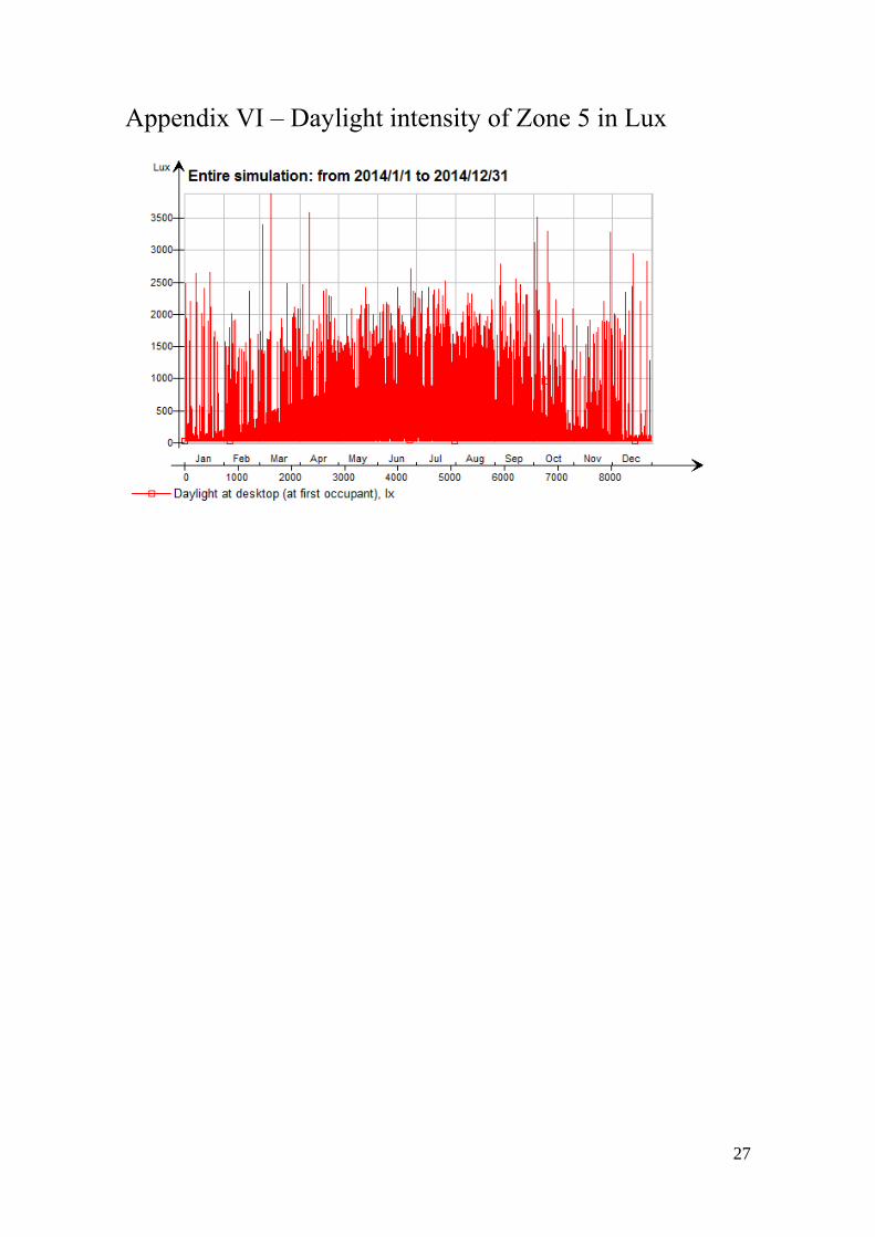
The indoor daylight intensity of the selected room (Zone 5) is calculated by IDA ICE
and showed in Appendix VI.
18
5. Discussion of additional measures
Beside measures discussed in the previous sections regarding the 4 indicators, improved
approaches of ventilation systems and lighting control are also significant for energy
saving of the building.
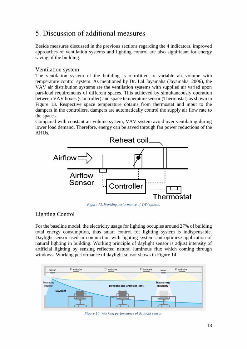
Ventilation system The ventilation system of the building is retrofitted to variable air volume with
temperature control system. As mentioned by Dr. Lal Jayamaha (Jayamaha, 2006), the
VAV air distribution systems are the ventilation systems with supplied air varied upon
part-load requirements of different spaces. This achieved by simultaneously operation
between VAV boxes (Controller) and space temperature sensor (Thermostat) as shown in
Figure 13. Respective space temperature obtains from thermostat and input to the
dampers in the controllers, dampers are automatically control the supply air flow rate to
the spaces.
Compared with constant air volume system, VAV system avoid over ventilating during
lower load demand. Therefore, energy can be saved through fan power reductions of the
AHUs.
Figure 13, Working performance of VAV system.
Lighting Control
For the baseline model, the electricity usage for lighting occupies around 27% of building
total energy consumption, thus smart control for lighting system is indispensable.
Daylight sensor used in conjunction with lighting system can optimize application of
natural lighting in building. Working principle of daylight sensor is adjust intensity of
artificial lighting by sensing reflected natural luminous flux which coming through
windows. Working performance of daylight sensor shows in Figure 14.
Figure 14, Working performance of daylight sensor.

19
The control set point of daylight at the workplace is limited between 100 lux to 750 lux
according to typical lux values recommended by AHRAE standard (ASHRAE, 2008) in
the optimized model. Meanwhile, the control strategy of light is changed from “Schedule”
to “Setpoints and Schedule”. Which means when the indoor daylight intensity is higher
than 750 lux, the artificial lighting is turned off. In the contrary, the artificial light is
staring to work when the reflected natural light is lower than 100 lux.
With implementation of lighting control and increased window areas, annual 0.8 kWh/m2
of electricity usage by lighting can be reduced.
20
6. Conclusion
The aim of this project was to improve energy performance and indoor climate of the
residential building, thereafter, made assessment of the building for 4 indicators
according to Miljöbyggnad certification requirements.
Compared with energy performance from simulation of baseline model, indicators of
specific energy use, thermal climate winter, thermal climate in summer and daylight have
been improved to GOLD level for Miljöbyggnad environmental assessment.
For further work regarding the rest Miljöbyggnad indicators, heat pumps, geothermal,
thermal storage and renewable energy technologies such as combined solar thermal and
PV panels are recommended to be implemented for reducing consumption of non-
renewable energy source from delivered energy of the building.

21
References Andaloro, A. P. F., Salomone, R., Ioppolo, G. & Andaloro, . L., 2010. Energy
certification of buildings: A comparative analysis of progress towards implementation
in European countries., Italy: ELSEVIER Energy Policy.
Asdrubali, F., Baldinelli, G., Bianchi, F. & Sambuco, S., 2015. A comparison between
environmental sustainability rating systems LEED and ITACA for residential buildings.,
Italy: ELSEVIER.
ASHRAE, 2008. ASHRAE Handbook: HVAC Systems & Equipment., Unite States:
ASHRAE.
BFS, 2011. 9. Energy Management, Sweden: BBR.
Engdahl, F. & Johansson, D., 2003. Optimal supply air temperature with respect to
energy use in a variable air volume system., Lund: Lund University.
ISO, 1994. ISO 7703:1994 Ergonomics of the thermal environment -- Analytical
determination and interpretation of thermal comfort using calculation of the PMV and
PPD indices and local thermal comfort criteria., Switzerland: International
Organization for Standardization.
Jayamaha, D. L., 2006. Energy-Efficient Building Systems - Green Strategies for
operation and maintance.. 1st ed. Unit States: McGraw-Hill.
Lee, W. L. & Burnett, J., 2007. Benchmarking energy use assessment of HK-BEAM,
BREEAM and LEED., Hong Kong: ScienceDirect.
McQuiston, F. C., Parker, J. D. & Spitler, J. D., 2005. Heating, Ventilating, and Air
Conditioning - Analysis and Design.. Sixth ed. Unit States: WILEY.
Molin, A., Rohdin, P. & Moshfegh, B., 2011. Investigation of energy performance of
newly built low-energy buildings in Sweden., Linköping: ELSEVIER.
SEA, 2008. Energy Mode (Swedish Energiläget), Eskilstuna: Swedish Energy Agency.
Seinre, E., Kurnitski, J. & Voll, H., 2014. Building sustainability objective assessment
in Estonian context and a comparative evaluation with LEED and BREEAM., Tallinn:
ELSEVIER.
SGBC, 2014. Sweden Green Building Council. [Online]
Available at: https://www.sgbc.se/dokument-och-manualer
SVEBY, 2012. Brukarindata bostäder, Stockholm: Branschstandard för energi i
byggnader.

22
Appendix I – Energy Performance (the First Floor)

23
Appendix II – Energy Performance (the Second Floor)

24
Appendix III – Energy Performance (the Third Floor)

25
Appendix IV – Energy Performance (the Fourth Floor)

26
Appendix V – Energy Performance (the Fifth Floor)
27
Appendix VI – Daylight intensity of Zone 5 in Lux

28
Appendix VII – Comfort indices of Zone 5.


![Miljöutredning av storhushåll215446/FULLTEXT01.pdf1.3.1 Miljö-FMEA Miljö-FMEA, (Failure Mode and Effect Analysis) feleffektsanalys [6] används som metod i denna rapport för att](https://img.pdfslide.us/doc/110x75/60d22b7237e80d58ad0cdc43/miljutredning-av-storhushll-215446fulltext01pdf-131-milj-fmea-milj-fmea.jpg)