Embed Size (px)
Citation preview

Entity-Relationship Modeling I
The cautious seldom err. Confucius

Class Outline What are the steps in designing databases? Why is modeling important? What are the basic elements of a database model? How are the following represented in Chen’s relational database
model? entity attribute degree of relationship connectivity cardinality binary M:N relationships participation

Data Modeling A model is a simplified representation (usually a graphic) of a
complex object in reality to make it understandable If the elements in the model are correctly associated with
elements in reality, the model can be used to solve problems in reality (e.g., engineer’s model to determine a bridge’s weight tolerance; if the model is incorrect...)
an ER model is an integrated set of concepts that describes data, relationships between data, and the constraints on the data as they are used within a specific organization; a data model renders organization’s (users’) view of objects and/or events and their associations
ER model is a blueprint from which a well-structured database is created
ER models are independent of details of implementation

E-R Modeling Concepts
Objects
Entities
Relationships
Attributes
Relationship Type
Degree
Values
Domains
1 : 1
1 : N
M : N
Mandatory
Optional
Connectivity
Participation
Recursive
Binary
Ternary
N-ary
Cardinality

Entities Entity
Something that can be identified in the users’ environment about which we want to store data; typically is a noun
Entities or objects must have occurrences that can be uniquely identified
Identified by an organization or its users Consists of tangible or intangible objects or events
Entity Instance A single entity occurrence or instance within a collection of entities
e.g., STUDENT is an entity; Annie Abel is an entity instance as are Bob Brown and Cathy Chen.
STUDENT

Attributes properties that describe characteristics of an entity - assumed all
instances of a given entity have the same attributes use atomic attributes, those that cannot be divided further (e.g., not composite
attributes (e.g., use last name & first name, not name) do not use derived attributes (attributes that can be calculated using other
attributes; e.g., age) use single value attributes not multi-valued (e.g., medication1, medication2,
etc.) multi-valued attributes, if they have their own important attributes should be
elevated to entities
e.g., attributes of the entity STUDENT might include name, address, etc.
STUDENT birth datefirst name
last namephotophone #

Identifier Each entity occurrence has a unique identifier The identifier is an attribute (or group of attributes)
that describes or identifies each entity occurrence An identifier should be unique to each occurrence Referred to as a ‘primary key’ in relational models
STUDENTe.g., in the list of potential attributes of the entity STUDENT, the identifier could be Student Number.
StudentID

Relationships Association or connection between two or more
entities Usually a verb HAS-A is also a common relationship
(EMPLOYEE-has a-DEPENDENT) E-R model also contains relationship classes
STUDENT takes COURSE
StudentID CourseID

Degree of Relationship: Binary
In a binary relationship, two entities are associated.This is the most common degree of relationship.
VACATIONER
takes
TRIP
EMPLOYEE
DEPARTMENT
works for

Degree of Relationship: Ternary
In a ternary relationship, three entities are associated
create
DESIGNER
WRITER ILLUSTRATOR
CUSTOMER
WAREHOUSE
ITEM
order

Degree of Relationship: Unary (Recursive)
In a recursive relationship, one entity is associated with itself
TEAM
plays
COURSE
requires

Child Toy
Employee Office
Musician Song
One-to-Many
One-to-One
Many-to-Many
1 M
M
1
N
1
Connectivity Connectivity describes constraints on relationship (also referred to as “maximum
cardinality”) Number of instances of entity B that can (or must) be associated with each instance of entity
A
has
has
sings

Representing M:N binary relationships M:N relationships are represented by two 1:M relationships. the relationship is itself an entity, called a composite entity
(rectangle around the diamond) The composite entity often has its own attributes
STUDENT CLASSenrolls inM N
STUDENT CLASSenrolls inM M
Date Mark
1 1

Cardinality Cardinality is the specific number of entity occurrences
associated with one occurrence of the related entity often referred to as ‘business rules’ because cardinality is
usually determined by organizational policy
Doctor Patients1 M
e.g., at a clinic, a given doctor may not have any patients or up to ten patients. A patient may not have any doctor (waiting to be seen) or may be assigned to one doctor.
(0,10) (0,1)has

Occurrences DiagramPictorial mapping of the occurrences between two entities assists in understanding connectivity, cardinality
D1 P1
D2 P2
D3 P3
D4 P4
D5 P5
D6 P6A doctor may see between 0 and 10 patients; a patient may only be seen by 0 or 1 doctors. 1 doctor may see many patients (1:M)

Relationship Participation Also referred to as “minimum cardinality” Mandatory Participation
An instance of a given entity must definitely match an instance of a second entity
e.g., each student must enroll in exactly one course
Optional Participation An instance of a given entity does not necessarily participate in the
relationship lower bound of cardinality is zero e.g., a faculty member teaches zero, one, or two courses
makes1
MEMBER DONATION
OPTIONALMANDATORY
N
(0,N) (1,1)
a member may or may not make a donation but a donation must be associated with a member

From the DOCTOR perspective:– a doctor may have many patients (M patients of 1:M
connectivity)– a doctor does not necessarily have patients (optional
participation of patients, cardinality is (0,N))
From the PATIENT perspective:– A patient has (associated with) one and only one doctor (1
doctor of 1:M connectivity)– A patient may or may not have (associated with) a doctor
(optional participation, cardinality is (0,1))
DOCTOR PATIENThas1 M
(0,N) (0,1)
Example: Doctor & Patient
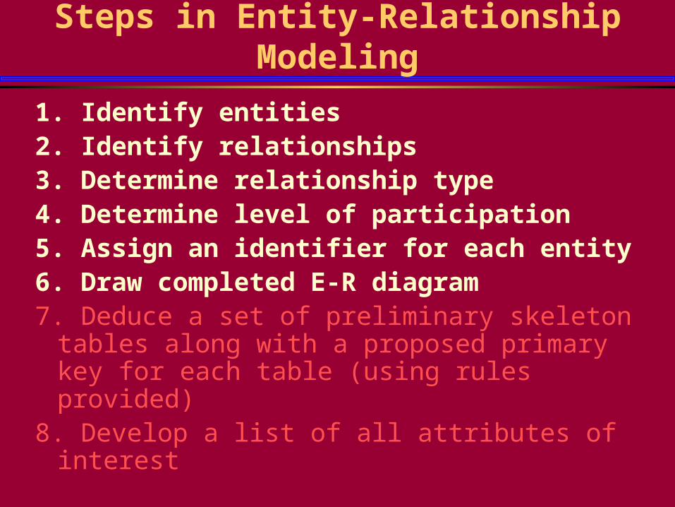
Steps in Entity-Relationship Modeling
1. Identify entities2. Identify relationships3. Determine relationship type4. Determine level of participation5. Assign an identifier for each entity6. Draw completed E-R diagram7. Deduce a set of preliminary skeleton tables along
with a proposed primary key for each table (using rules provided)
8. Develop a list of all attributes of interest

E-R Method Example: Scheduling DB
Step 1. Identify entity types
APPOINTMENT
DOCTOR PATIENT
Step 2. Identify relationships
DOCTOR APPhas
PATIENT APPhas

Schedule Database (cont’d) Step 3. Determine relationship type. Ask:
How many appointments can a patient have? Can an appointment involve many patients?Each patient may have many appointments but an appointment involves only one patient. The relationship type is one-to-many or:
PATEINT APPhas1 N
How many appointments can a doctor have? Can many doctors be involved in one appointment?. The relationship type is many-to-many because a doctor may have many appointments and an appointment may involve 1 or more doctors.
DOCTOR APPhasNM

Schedule Database (cont’d)
Step 4. Determine level of participation Since each patient does not need to have an appointment
(walk-in) it is considered optional. BUT, each appointment must have a patient, hence it is considered mandatory.
PATEINT APPhas1 N
(0, N) (1, 1) For the doctor-appointment relationship, a doctor does not need to
have an appointment so it is considered optional. BUT, each appointment must have a doctor, hence it is considered mandatory.
M NDOCTOR APPhas
(0, N) (1,M)

Schedule Database (cont’d)
Step 5. Assign an identifier for each entity DoctorId, PatientId, AppointmentId
Step 6. Draw completed E-R diagram
Patient
Doctor Apphas
has
DoctorId, ...
AppId, ...
PatientID, ...
N
1
NM(0,N) (1,M) (1,1)
(0,N)

Schedule Database (cont’d)
Step 6. Draw completed E-R diagram - resolve M:N relationships
Patient
Doctor Apphas
has
DoctorId, ...
AppId, ...
N
1
NM(0,N) (1,M) (1,1)
(0,N)
AppId ...
DoctorId ...
PatientID, ...


![Confucius - Essential Confucius [Trans. Cleary] (HarperCollins, 1992)](https://img.pdfslide.us/doc/110x75/55cf9709550346d0338f650b/confucius-essential-confucius-trans-cleary-harpercollins-1992.jpg)