Embed Size (px)
Citation preview
Enterprise Cloud
Functional Description
[Global Standard Services]
NTT Communications
Ver.2.86
(June 15th, 2016 Edition)
Enterprise Cloud Functional Description
2
About This Document
[Structure of This Document]
The document is composed of three parts.
Overview part 1 Overview of the Enterprise Cloud
Features part 2 Service Management (Portal Site)
3 Compute (Global Standard Menu)
4 Backup (Global Standard Menu)
5 Network (Global Standard Menu)
6 External Storage (Global Standard Menu)
7 Security (Global Standard Menu)
Maintenance
part
8 Maintenance and Operation of the Enterprise Cloud (Japan Contract)
[Purpose of This Document/How to Use This Document]
This document explains the menus in the Enterprise Cloud and the features in
each menu. Please note that the information in this document is for users.
If anything in the document is unclear, please contact an NTT sales representative
or Support. The contact information for Support is included in this document.
For instructions on how to use the Customer Portal, refer to "Enterprise Cloud User's
Guide."
The service may differ from the information in this document as a result of feature
additions/changes. You can download the latest version of this document and user
guides from the website below.
Information for Users who have signed contracts only
- You will need the ID/password provided when you started the service, or sent
separately, to access and use the service.
http://www.ntt.com/bhec/data/support.html
General Information (Knowledge Center)
https://ecl.ntt.com/en
Enterprise Cloud Functional Description
3
Contents
About This Document ............................................................................. 2
Contents ............................................................................................... 3
1. Overview of the Enterprise Cloud ......................................................... 11
1.1 What is Enterprise Cloud? ................................................................ 11
1.2 Features that make up Enterprise Cloud ............................................ 12
1.3 Services Available at All Data Centers (Global Standard Menu) ............. 15
Available Equipment Environment ........................................ 19 1.3.1
Available Data Centers ........................................................ 23 1.3.2
Service Order, Delivery Time and Minimum Usage Period ........ 27 1.3.3
Resource Contract Conditions and Service Combination 1.3.4
Conditions ......................................................................... 30
1.4 Services That Have Data Center-Specific Usage (Local Option Menu) .... 32
1.5 Example Usage Model ..................................................................... 34
1.6 Explanation of Common Terms ........................................................ 36
1.7 Restrictions.................................................................................... 39
2. Service Management (Portal Site) ........................................................ 40
40
2.1 Enterprise Cloud Customer Portal ..................................................... 40
Available Features .............................................................. 40 2.1.1
List of Items That Can Be Controlled .................................... 42 2.1.2
Each Type of Permissions .................................................... 45 2.1.3
Important Points ................................................................ 51 2.1.4
2.2 Security Web Portal ........................................................................ 53
Available Features .............................................................. 54 2.2.1
Important Points ................................................................ 56 2.2.2
3. Compute (Global Standard Menu) ........................................................ 57
57
3.1 Compute Resource ......................................................................... 57
Available Features .............................................................. 57 3.1.1
Provision of Compute Resource Pools .................................... 58 3.1.2
Features for Controlling Compute Resource Pools ................... 61 3.1.3
vApp Feature ..................................................................... 62 3.1.4

Enterprise Cloud Functional Description
4
Assigning Resources to a Virtual Machine .............................. 62 3.1.5
Snapshot........................................................................... 78 3.1.6
Important Points ................................................................ 82 3.1.7
3.2 Compute Resource (Dedicated Device) .............................................. 87
Available Features .............................................................. 87 3.2.1
Provision of Compute Resource Pools .................................... 88 3.2.2
Parameter Settings for Resources ......................................... 94 3.2.3
Assigning Resources to a Virtual Machine .............................. 96 3.2.4
Important Points ................................................................ 98 3.2.5
3.3 Private Catalog ............................................................................... 99
Available Features .............................................................. 99 3.3.1
Provision of a Disk for Saving Template Catalogs .................. 100 3.3.2
Create Template Feature ................................................... 100 3.3.3
Import Template Feature .................................................. 101 3.3.4
Export Template Feature ................................................... 105 3.3.5
Important Points .............................................................. 106 3.3.6
3.4 OS License .................................................................................. 108
Available Features ............................................................ 108 3.4.1
Provision of an OS License ................................................. 108 3.4.2
Provision of a Public Catalog .............................................. 109 3.4.3
OS License Switching ........................................................ 109 3.4.4
Important Points .............................................................. 110 3.4.5
3.5 Database License (MS SQL) ........................................................... 114
Available Features ............................................................ 114 3.5.1
Provision of a Database License ......................................... 114 3.5.2
Provision of a Public Catalog .............................................. 114 3.5.3
Important Points .............................................................. 115 3.5.4
Initial State of Microsoft SQL Server ................................... 117 3.5.5
3.6 Database License (Oracle SE One) .................................................. 129
Availabile Features/Services .............................................. 129 3.6.1
Service Details, and Notes about Use/Design ....................... 131 3.6.2
Restrictions ..................................................................... 137 3.6.3
Operation and maintenance of the service ........................... 138 3.6.4
Bring Your Own License (BYOL) for Oracle License (Japan 3.6.5
Contract Only) ................................................................. 138
3.7 Database License (Oracle EE) ........................................................ 140

Enterprise Cloud Functional Description
5
Availabile Features/Services .............................................. 140 3.7.1
Service Details, and Notes about Use/Design ....................... 142 3.7.2
Restrictions ..................................................................... 145 3.7.3
Operation and maintenance of the service ........................... 146 3.7.4
3.8 Microsoft SAL (RDS SAL) ............................................................... 147
Available Features ............................................................ 147 3.8.1
Provision of an RDS SAL .................................................... 148 3.8.2
Provision of a Public Catalog .............................................. 148 3.8.3
Important Points .............................................................. 149 3.8.4
3.9 Backup License (Acronis) ............................................................... 150
Available Features ............................................................ 150 3.9.1
Important Points .............................................................. 150 3.9.2
Restriction ....................................................................... 150 3.9.3
3.10 HULFT License ............................................................................ 152
Overview ........................................................................ 152 3.10.1
Available Products ............................................................ 152 3.10.2
Important Points on Usage & Architecture ........................... 153 3.10.3
Restrictions ..................................................................... 153 3.10.4
4. Backup (Global Standard Menu) ........................................................ 154
154
4.1 Image Backup .............................................................................. 154
Available Features .............................................................. 154 4.1.1
Backup and Restore............................................................ 154 4.1.2
Backup and Restore Management .......................................... 156 4.1.3
Important Points ................................................................. 158 4.1.4
4.2 File Backup ................................................................................... 162
Available Features .............................................................. 162 4.2.1
Backup File Storage .......................................................... 163 4.2.2
Backup File Restore ............................................................ 164 4.2.3
Backup and Restore Management .......................................... 164 4.2.4
Important Points ................................................................. 166 4.2.5
5. Network Features (Global Standard Menu) .......................................... 170
170
5.1 Internet Connectivity .................................................................... 170
Available Features ............................................................ 170 5.1.1

Enterprise Cloud Functional Description
6
An Internet GW Is Provided ............................................... 170 5.1.2
Global IP Addresses Are Provided ....................................... 171 5.1.3
Important Points .............................................................. 173 5.1.4
5.2 VPN Connectivity .......................................................................... 174
Available Features ............................................................ 174 5.2.1
VPN Gateway ................................................................... 174 5.2.2
VPN Routing Settings ........................................................ 175 5.2.3
Enterprise Cloud and VPN Routing Design ........................... 175 5.2.4
Important Points .............................................................. 177 5.2.5
5.3 Server Segment ........................................................................... 179
Available Features ............................................................ 179 5.3.1
Server Segments Are Provided ........................................... 179 5.3.2
Important Points .............................................................. 185 5.3.3
5.4 Service Interconnectivity ............................................................... 186
Available Features ............................................................ 186 5.4.1
Service Interconnect Gateway ........................................... 187 5.4.2
Routing Settings .............................................................. 187 5.4.3
Important Points .............................................................. 188 5.4.4
5.5 Colocation Interconnectivity ........................................................... 189
Available Features ............................................................ 189 5.5.1
Layer 2 (L2) Connection .................................................... 189 5.5.2
Important Points .............................................................. 193 5.5.3
5.6 On-Premises Interconnectivity ....................................................... 194
Available Features ............................................................ 194 5.6.1
Layer 2 (L2) Connection .................................................... 194 5.6.2
Important Points .............................................................. 199 5.6.3
5.7 vFirewall ..................................................................................... 200
Available Features ............................................................ 201 5.7.1
Routing Feature ............................................................... 202 5.7.2
Firewall Feature ............................................................... 203 5.7.3
Packet Filtering Feature .................................................... 205 5.7.4
NAT/NAPT Feature ........................................................... 206 5.7.5
Features that the log dedicated portal provides .................... 206 5.7.6
Important Points .............................................................. 207 5.7.7
5.8 vLoad Balancer ............................................................................ 208
Available Features ............................................................ 209 5.8.1
Enterprise Cloud Functional Description
7
Load Balancing Feature ..................................................... 209 5.8.2
Routing Feature ............................................................... 212 5.8.3
IP Address Delivery Feature ............................................... 212 5.8.4
Important Points .............................................................. 214 5.8.5
Reference Information ...................................................... 214 5.8.6
5.9 Integrated Network Appliance ........................................................ 217
Available Features ............................................................ 218 5.9.1
Firewall Feature ............................................................... 220 5.9.2
NAT/NAPT Feature ........................................................... 221 5.9.3
Routing Feature ............................................................... 223 5.9.4
Load Balancing Feature ..................................................... 224 5.9.5
IPsec Termination Function ............................................... 227 5.9.6
Important Points .............................................................. 230 5.9.7
Reference Information ...................................................... 232 5.9.8
6. External Storage (Global Standard Menu) ........................................... 233
233
6.1 Global File Storage (Global Data Backup) ......................................... 233
Available Features ............................................................ 234 6.1.1
Provides Storage for Saving Data ....................................... 234 6.1.2
Data Replication Feature (Burst Feature)............................. 236 6.1.3
Important Points .............................................................. 238 6.1.4
7. Security Features (Global Standard Menu) .......................................... 240
240
7.1 IPS/IDS ....................................................................................... 240
Available Features ............................................................ 240 7.1.1
IPS/IDS Feature ............................................................... 240 7.1.2
Important Points .............................................................. 242 7.1.3
7.2 Email Anti-Virus ........................................................................... 244
Available Features ............................................................ 244 7.2.1
Virus Scan Feature ........................................................... 244 7.2.2
Important Points .............................................................. 246 7.2.3
7.3 Web Anti-Virus ............................................................................. 248
Available Features ............................................................ 248 7.3.1
Virus Scan Feature ........................................................... 248 7.3.2
Important Points .............................................................. 250 7.3.3
Enterprise Cloud Functional Description
8
7.4 URL Filtering ................................................................................ 252
Available Features ............................................................ 252 7.4.1
URL Filtering Feature ........................................................ 252 7.4.2
Important Points .............................................................. 255 7.4.3
7.5 Application Filtering ...................................................................... 257
Available Features ............................................................ 257 7.5.1
Application Filtering Feature .............................................. 257 7.5.2
Important Points .............................................................. 259 7.5.3
7.6 Web Application Firewall (WAF) ..................................................... 261
Available Features ............................................................ 261 7.6.1
Web Application Firewall Feature ........................................ 261 7.6.2
Important Points .............................................................. 265 7.6.3
7.7 UTM............................................................................................ 266
Available Features ............................................................ 266 7.7.1
IPS/IDS ........................................................................... 268 7.7.2
Anti Virus ........................................................................ 269 7.7.3
Web Filter ........................................................................ 270 7.7.4
Spam Filter ...................................................................... 272 7.7.5
Important Points ............................................................... 273 7.7.6
7.8 Web Security (WAF) ..................................................................... 275
Available Features ............................................................ 275 7.8.1
WAF ............................................................................... 276 7.8.2
IP reputation ................................................................... 277 7.8.3
Important Points .............................................................. 278 7.8.4
7.9 VM Anti-Virus ............................................................................... 280
Available Features ............................................................ 280 7.9.1
Real-Time Scan Feature .................................................... 280 7.9.2
Scheduled Scan Feature .................................................... 281 7.9.3
Actions ........................................................................... 282 7.9.4
Scan Exception Feature ..................................................... 284 7.9.5
Pattern File Automatic Update Feature ................................ 284 7.9.6
Important Points .............................................................. 284 7.9.7
7.10 VM Virtual Patch .......................................................................... 288
Available Features ............................................................ 288 7.10.1
VM Virtual Patch Feature ................................................... 288 7.10.2
Recommended Scan Feature ............................................. 289 7.10.3
Enterprise Cloud Functional Description
9
Important Points .............................................................. 290 7.10.4
7.11 VM Firewall ................................................................................. 293
Available Features ............................................................ 293 7.11.1
VM Firewall ..................................................................... 293 7.11.2
Important Points .............................................................. 294 7.11.3
7.12 Application Profiling ..................................................................... 297
Available Features ............................................................ 297 7.12.1
Application Profiling Report ................................................ 297 7.12.2
Important Points .............................................................. 299 7.12.3
7.13 Network Profiling ......................................................................... 301
Available Features ............................................................ 301 7.13.1
Network Profiling Report ................................................... 301 7.13.2
Important Points .............................................................. 303 7.13.3
7.14 RTMD Web ................................................................................. 305
Available Features ............................................................ 305 7.14.1
File Analysis Feature ......................................................... 305 7.14.2
Traffic Analysis Feature ..................................................... 306 7.14.3
Report Feature ................................................................. 307 7.14.4
Important Points .............................................................. 307 7.14.5
7.15 RTMD Email ................................................................................ 309
Available Features ............................................................ 309 7.15.1
File Analysis Feature ......................................................... 309 7.15.2
Important Points .............................................................. 311 7.15.3
8. Maintenance and Operation of the Enterprise Cloud (Japan Contract) ...... 312
312
8.1 Set of Materials Sent When You Start Using the Service .................... 312
8.2 Customer Support ........................................................................ 313
Support Center/Technical Help Desk ................................... 313 8.2.1
Maintenance and Operations System .................................. 314 8.2.2
8.3 Contact When a Failure Occurs....................................................... 315
Items Monitored Remotely and Procedures for Notifying Users316 8.3.1
Remote Monitoring System ................................................ 317 8.3.2
8.4 Maintenance Information ............................................................... 319
8.5 Limitations to Maintenance Operations ............................................ 320
Index ................................................................................................ 321

Enterprise Cloud Functional Description
10
[Revision History] .............................................................................. 323
Enterprise Cloud Functional Description
11
1. Overview of the Enterprise Cloud
1.1 What is Enterprise Cloud?
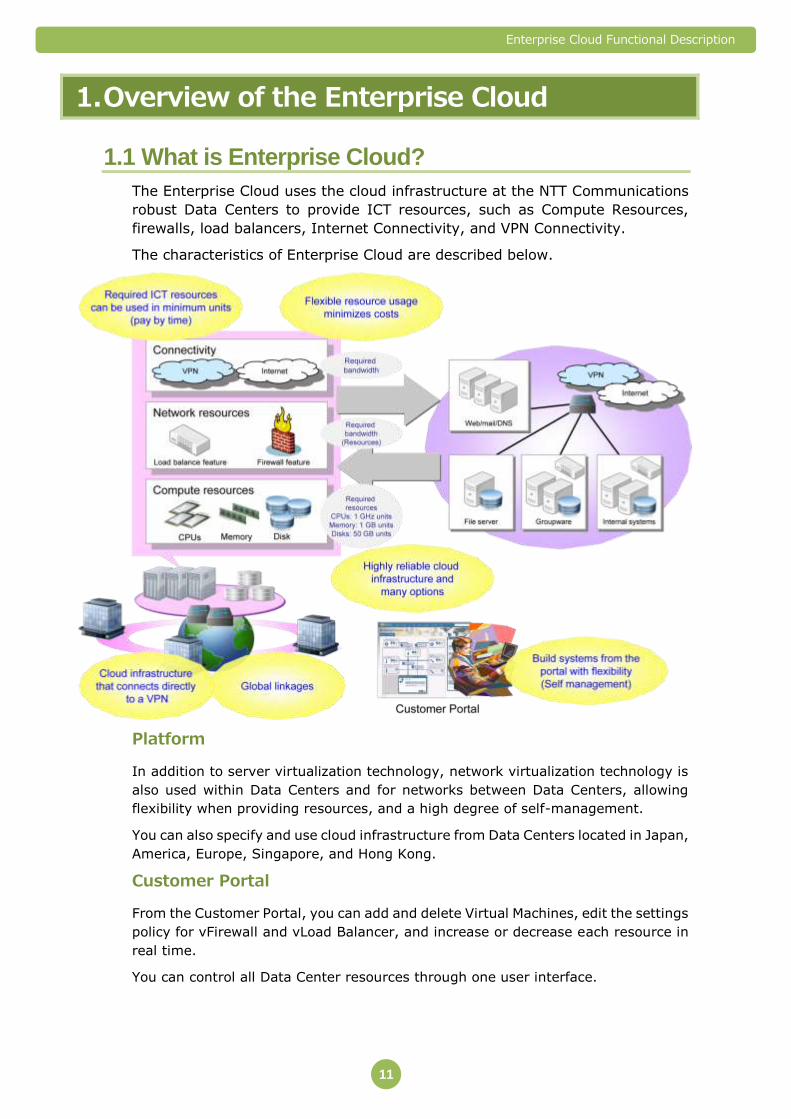
The Enterprise Cloud uses the cloud infrastructure at the NTT Communications
robust Data Centers to provide ICT resources, such as Compute Resources,
firewalls, load balancers, Internet Connectivity, and VPN Connectivity.
The characteristics of Enterprise Cloud are described below.
Platform
In addition to server virtualization technology, network virtualization technology is
also used within Data Centers and for networks between Data Centers, allowing
flexibility when providing resources, and a high degree of self-management.
You can also specify and use cloud infrastructure from Data Centers located in Japan,
America, Europe, Singapore, and Hong Kong.
Customer Portal
From the Customer Portal, you can add and delete Virtual Machines, edit the settings
policy for vFirewall and vLoad Balancer, and increase or decrease each resource in
real time.
You can control all Data Center resources through one user interface.
Enterprise Cloud Functional Description
12
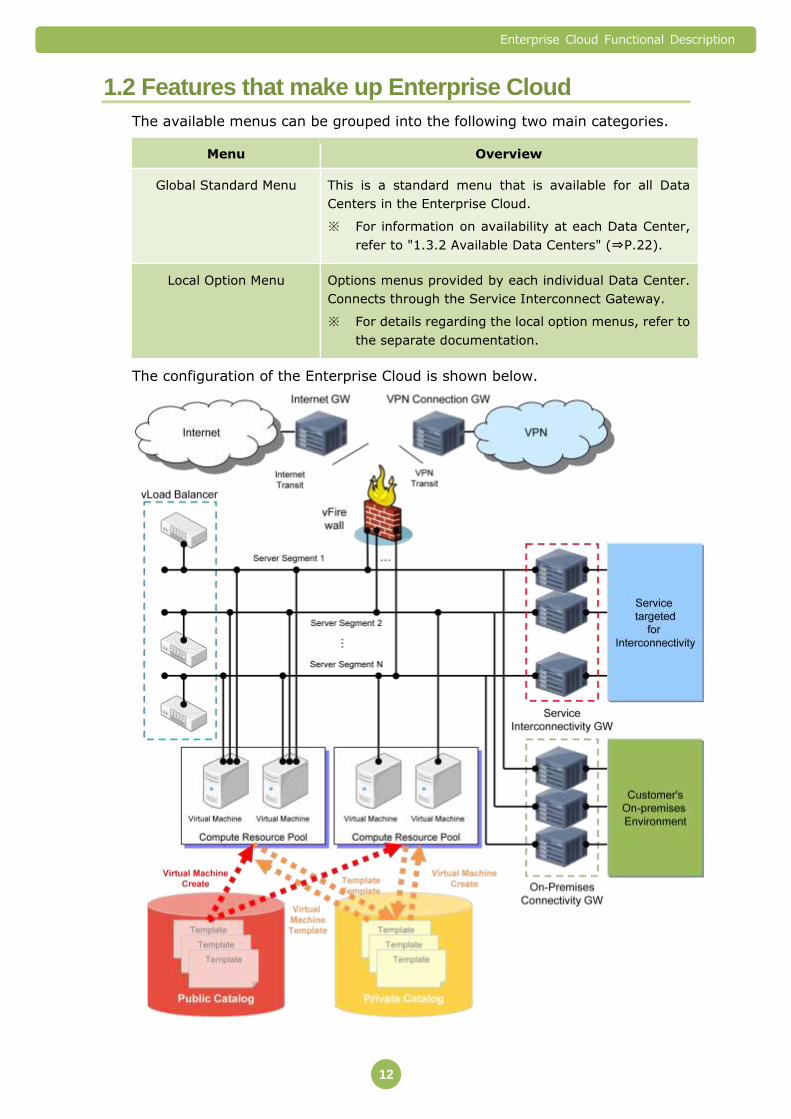
1.2 Features that make up Enterprise Cloud
The available menus can be grouped into the following two main categories.
Menu Overview
Global Standard Menu This is a standard menu that is available for all Data
Centers in the Enterprise Cloud.
※ For information on availability at each Data Center,
refer to "1.3.2 Available Data Centers" (⇒P.22).
Local Option Menu Options menus provided by each individual Data Center.
Connects through the Service Interconnect Gateway.
※ For details regarding the local option menus, refer to
the separate documentation.
The configuration of the Enterprise Cloud is shown below.
Enterprise Cloud Functional Description
13
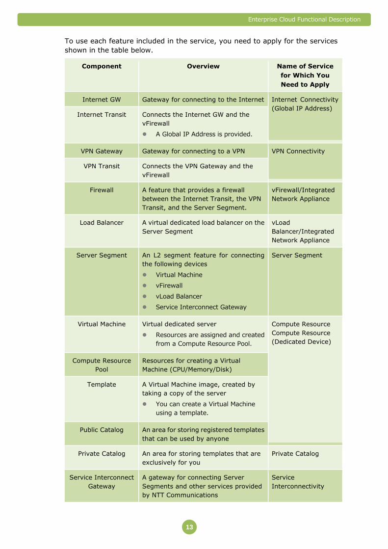
To use each feature included in the service, you need to apply for the services
shown in the table below.
Component Overview Name of Service
for Which You
Need to Apply
Internet GW Gateway for connecting to the Internet Internet Connectivity
(Global IP Address) Internet Transit Connects the Internet GW and the
vFirewall
A Global IP Address is provided.
VPN Gateway Gateway for connecting to a VPN VPN Connectivity
VPN Transit Connects the VPN Gateway and the
vFirewall
Firewall A feature that provides a firewall
between the Internet Transit, the VPN
Transit, and the Server Segment.
vFirewall/Integrated
Network Appliance
Load Balancer A virtual dedicated load balancer on the
Server Segment
vLoad
Balancer/Integrated
Network Appliance
Server Segment An L2 segment feature for connecting
the following devices
Virtual Machine
vFirewall
vLoad Balancer
Service Interconnect Gateway
Server Segment
Virtual Machine Virtual dedicated server
Resources are assigned and created
from a Compute Resource Pool.
Compute Resource
Compute Resource
(Dedicated Device)
Compute Resource
Pool
Resources for creating a Virtual
Machine (CPU/Memory/Disk)
Template A Virtual Machine image, created by
taking a copy of the server
You can create a Virtual Machine
using a template.
Public Catalog An area for storing registered templates
that can be used by anyone
Private Catalog An area for storing templates that are
exclusively for you
Private Catalog
Service Interconnect
Gateway
A gateway for connecting Server
Segments and other services provided
by NTT Communications
Service
Interconnectivity

Enterprise Cloud Functional Description
14
Component Overview Name of Service
for Which You
Need to Apply
Global File Storage
(Global Data Backup)
A feature for backing up the desired
data to a remote (Japan or overseas)
Data Center
Provided through the Service
Interconnect Gateway.
Global File Storage
(Global Data Backup)
On-Premises GW A gateway that provides an L2
connection to Server Segments in
your system environment (called the
"On-Premises Environment" below)
within your own operating system
environment.
On-Premises
Interconnectivity
Colocation
Interconnectivity
Provides a secure L2 connection
between the Server segment and
Customer Colocation
Colocation
Interconnectivity
Other Service
Environment
Unique services offered by each Data
Center
They can be used in conjunction
with Enterprise Cloud.
Local Option Menu

Enterprise Cloud Functional Description
15
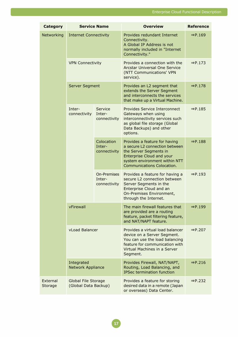
1.3 Services Available at All Data Centers (Global Standard Menu)
In Enterprise Cloud, you can use the following menus at all Data Centers.
Category Service Name Overview Reference
Compute Compute
Resource
Compute
Class
Provides the CPUs and Memory
for creating a Virtual Machine
by virtualizing a physical server
shared by multiple users.
⇒P.56
Storage
Class
Provides the Disks for creating
a Virtual Machine by
virtualizing storage devices
shared by multiple users.
⇒P.56
Compute
Resource
(Dedicated
Device)
Compute
Class
Provides the CPUs and Memory
for creating a Virtual Machine
by virtualizing a physical server
dedicated to you.
⇒P.86
Storage
Class
Provides the Disks for creating
a Virtual Machine by
virtualizing a storage device
dedicated to you.
⇒P.86
Private Catalog Provides a Disk for storing
templates of the Virtual
Machines that you create.
You can quickly create new
Virtual Machines from the
saved templates.
⇒P.98 Lic
ense
OS Windows
Server
Provides a Microsoft Windows
Server license for Virtual
Machines.
⇒P.107
Red Hat
Enterprise
Linux
Provides a Red Hat Enterprise
Linux subscription for Virtual
Machines.
⇒P.107
Database Provides a Microsoft SQL
Server license for Virtual
Machines.
⇒P.113
Microsoft
SAL
RDS SAL Provides a Microsoft Remote
Desktop Service Subscriber
Access License.
⇒P.128
Backup
License
Acronis Provides backup software
license for Virtual Machines.
⇒P.149

Enterprise Cloud Functional Description
16
Category Service Name Overview Reference
Image Backup Provides a feature for backing
up the current state of an entire
Virtual Machine.
⇒P.153
File Backup Provides a feature for backing
up files and folder in Virtual
Machine.
⇒P.110
Enterprise Cloud Functional Description
17
Category Service Name Overview Reference
Networking Internet Connectivity Provides redundant Internet
Connectivity.
A Global IP Address is not
normally included in "Internet
Connectivity."
⇒P.169
VPN Connectivity Provides a connection with the
Arcstar Universal One Service
(NTT Communications' VPN
service).
⇒P.173
Server Segment Provides an L2 segment that
extends the Server Segment
and interconnects the services
that make up a Virtual Machine.
⇒P.178
Inter-
connectivity
Service
Inter-
connectivity
Provides Service Interconnect
Gateways when using
interconnectivity services such
as global file storage (Global
Data Backups) and other
options.
⇒P.185
Colocation
Inter-
connectivity
Provides a feature for having
a secure L2 connection between
the Server Segments in
Enterprise Cloud and your
system environment within NTT
Communications Colocation.
⇒P.188
On-Premises
Inter-
connectivity
Provides a feature for having a
secure L2 connection between
Server Segments in the
Enterprise Cloud and an
On-Premises Environment,
through the Internet.
⇒P.193
vFirewall The main firewall features that
are provided are a routing
feature, packet filtering feature,
and NAT/NAPT feature.
⇒P.199
vLoad Balancer Provides a virtual load balancer
device on a Server Segment.
You can use the load balancing
feature for communication with
Virtual Machines in a Server
Segment.
⇒P.207
Integrated
Network Appliance
Provides Firewall, NAT/NAPT,
Routing, Load Balancing, and
IPSec termination function
⇒P.216
External
Storage
Global File Storage
(Global Data Backup)
Provides a feature for storing
desired data in a remote (Japan
or overseas) Data Center.
⇒P.232
Enterprise Cloud Functional Description
18
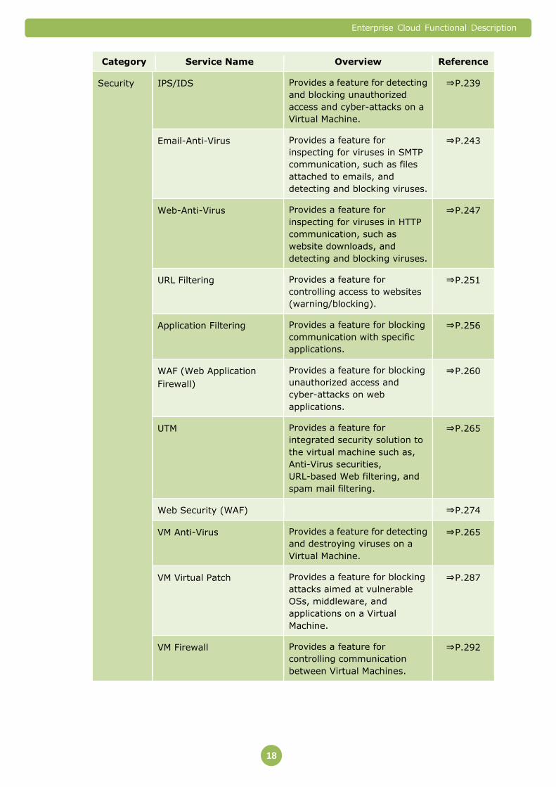
Category Service Name Overview Reference
Security IPS/IDS Provides a feature for detecting
and blocking unauthorized
access and cyber-attacks on a
Virtual Machine.
⇒P.239
Email-Anti-Virus Provides a feature for
inspecting for viruses in SMTP
communication, such as files
attached to emails, and
detecting and blocking viruses.
⇒P.243
Web-Anti-Virus Provides a feature for
inspecting for viruses in HTTP
communication, such as
website downloads, and
detecting and blocking viruses.
⇒P.247
URL Filtering Provides a feature for
controlling access to websites
(warning/blocking).
⇒P.251
Application Filtering Provides a feature for blocking
communication with specific
applications.
⇒P.256
WAF (Web Application
Firewall)
Provides a feature for blocking
unauthorized access and
cyber-attacks on web
applications.
⇒P.260
UTM Provides a feature for
integrated security solution to
the virtual machine such as,
Anti-Virus securities,
URL-based Web filtering, and
spam mail filtering.
⇒P.265
Web Security (WAF) ⇒P.274
VM Anti-Virus Provides a feature for detecting
and destroying viruses on a
Virtual Machine.
⇒P.265
VM Virtual Patch Provides a feature for blocking
attacks aimed at vulnerable
OSs, middleware, and
applications on a Virtual
Machine.
⇒P.287
VM Firewall Provides a feature for
controlling communication
between Virtual Machines.
⇒P.292
Enterprise Cloud Functional Description
19
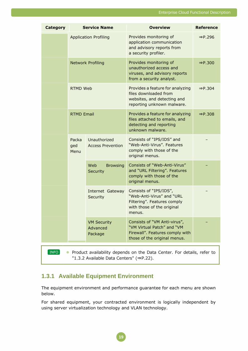
Category Service Name Overview Reference
Application Profiling Provides monitoring of
application communication
and advisory reports from
a security profiler.
⇒P.296
Network Profiling Provides monitoring of
unauthorized access and
viruses, and advisory reports
from a security analyst.
⇒P.300
RTMD Web Provides a feature for analyzing
files downloaded from
websites, and detecting and
reporting unknown malware.
⇒P.304
RTMD Email Provides a feature for analyzing
files attached to emails, and
detecting and reporting
unknown malware.
⇒P.308
Packa
ged
Menu
Unauthorized
Access Prevention
Consists of “IPS/IDS” and
“Web-Anti-Virus”. Features
comply with those of the
original menus.
-
Web Browsing
Security
Consists of “Web-Anti-Virus”
and “URL Filtering”. Features
comply with those of the
original menus.
-
Internet Gateway
Security
Consists of “IPS/IDS”,
“Web-Anti-Virus” and “URL
Filtering”. Features comply
with those of the original
menus.
-
VM Security
Advanced
Package
Consists of “VM Anti-virus”,
“VM Virtual Patch” and “VM
Firewall”. Features comply with
those of the original menus.
-
Product availability depends on the Data Center. For details, refer to
"1.3.2 Available Data Centers" (⇒P.22).
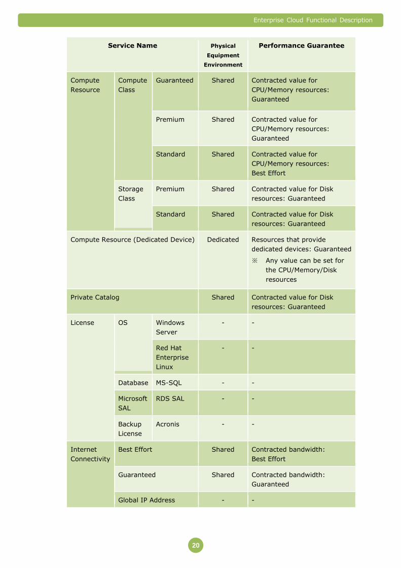
Available Equipment Environment 1.3.1
The equipment environment and performance guarantee for each menu are shown
below.
For shared equipment, your contracted environment is logically independent by
using server virtualization technology and VLAN technology.
Enterprise Cloud Functional Description
20
Service Name Physical
Equipment
Environment
Performance Guarantee
Compute
Resource
Compute
Class
Guaranteed Shared Contracted value for
CPU/Memory resources:
Guaranteed
Premium Shared Contracted value for
CPU/Memory resources:
Guaranteed
Standard Shared Contracted value for
CPU/Memory resources:
Best Effort
Storage
Class
Premium Shared Contracted value for Disk
resources: Guaranteed
Standard Shared Contracted value for Disk
resources: Guaranteed
Compute Resource (Dedicated Device) Dedicated Resources that provide
dedicated devices: Guaranteed
※ Any value can be set for
the CPU/Memory/Disk
resources
Private Catalog Shared Contracted value for Disk
resources: Guaranteed
License OS Windows
Server
- -
Red Hat
Enterprise
Linux
- -
Database MS-SQL - -
Microsoft
SAL
RDS SAL - -
Backup
License
Acronis - -
Internet
Connectivity
Best Effort Shared Contracted bandwidth:
Best Effort
Guaranteed Shared Contracted bandwidth:
Guaranteed
Global IP Address - -

Enterprise Cloud Functional Description
21
Service Name Physical
Equipment
Environment
Performance Guarantee
VPN
Connectivity
Best Effort Shared Contracted bandwidth:
Best Effort
Guaranteed Shared Contracted bandwidth:
Guaranteed
Server Segment Shared Bandwidth for traffic usage:
Best Effort
Interconnectivity Service Inter-
connectivity
Shared Bandwidth for traffic usage:
Best Effort
Colocation Inter-
connectivity
Shared Bandwidth for traffic usage:
Best Effort
On-Premises
Inter-
connectivity
Devices in
the Data
Center:
Shared
Devices in
the
On-Premises
Environment
: Dedicated
Contracted bandwidth:
Best Effort
vFirewall Shared Resource processing capacity:
Maximum value guaranteed
vLoad Balancer Shared Resource processing capacity:
Maximum value guaranteed
Integrated Network Appliance Shared Resource processing capacity:
Best Effort.
Global File Storage
(Global Data Backup)
Shared Contracted Disk capacity:
Guaranteed
Bandwidth usage: Best Effort
IPS/IDS Shared Amount of traffic: Best Effort
Email-Anti-Virus Shared Amount of traffic: Best Effort
Web-Anti-Virus Shared Amount of traffic: Best Effort
URL Filtering Shared Amount of traffic: Best Effort
Application Filtering Shared Amount of traffic: Best Effort
Web Application Firewall (WAF) Dedicated Amount of traffic: Best Effort
UTM - Amount of traffic: Best Effort
Enterprise Cloud Functional Description
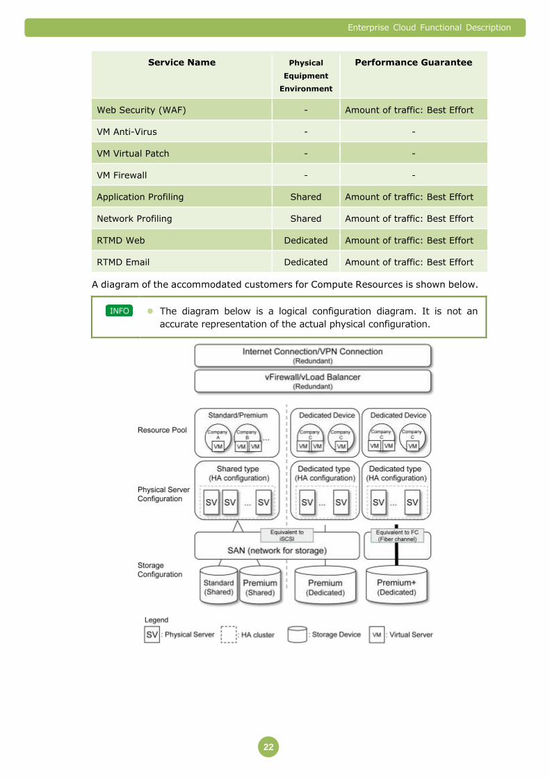
22
Service Name Physical
Equipment
Environment
Performance Guarantee
Web Security (WAF) - Amount of traffic: Best Effort
VM Anti-Virus - -
VM Virtual Patch - -
VM Firewall - -
Application Profiling Shared Amount of traffic: Best Effort
Network Profiling Shared Amount of traffic: Best Effort
RTMD Web Dedicated Amount of traffic: Best Effort
RTMD Email Dedicated Amount of traffic: Best Effort
A diagram of the accommodated customers for Compute Resources is shown below.
The diagram below is a logical configuration diagram. It is not an
accurate representation of the actual physical configuration.
Enterprise Cloud Functional Description
23
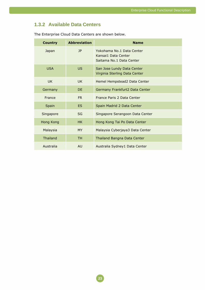
Available Data Centers 1.3.2
The Enterprise Cloud Data Centers are shown below.
Country Abbreviation Name
Japan JP Yokohama No.1 Data Center
Kansai1 Data Center
Saitama No.1 Data Center
USA US San Jose Lundy Data Center
Virginia Sterling Data Center
UK UK Hemel Hempstead2 Data Center
Germany DE Germany Frankfurt2 Data Center
France FR France Paris 2 Data Center
Spain ES Spain Madrid 2 Data Center
Singapore SG Singapore Serangoon Data Center
Hong Kong HK Hong Kong Tai Po Data Center
Malaysia MY Malaysia Cyberjaya3 Data Center
Thailand TH Thailand Bangna Data Center
Australia AU Australia Sydney1 Data Center

Enterprise Cloud Functional Description
24
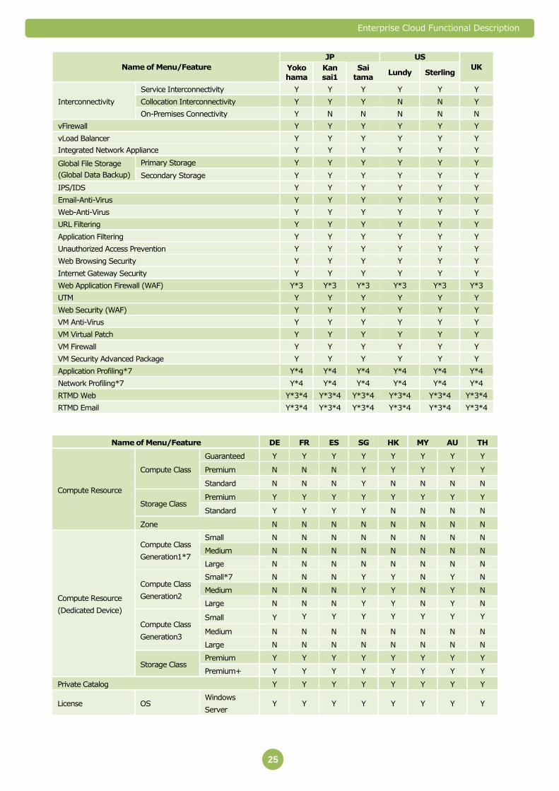
Services Provided by Each Data Center
The services that can be used at each Data Center are shown below.
Name of Menu/Feature
JP US
UK Yoko
hama
Kan
sai1
Sai
tama Lundy Sterling
Compute Resource
Compute Class
Guaranteed Y Y Y Y Y Y
Premium Y Y N Y Y Y
Standard Y Y N Y Y Y
Storage Class Premium Y Y Y Y Y Y
Standard Y Y Y Y Y Y
Zone*1 Y Y Y N N N
Compute Resource
(Dedicated Device)
Compute Class
Generation1*7
Small Y Y Y N N N
Medium N N N N N N
Large Y Y Y N N N
Compute Class
Generation2
Small*7 Y Y Y Y Y N
Medium Y Y Y Y Y Y
Large Y Y Y Y Y N
Compute Class
Generation3
Small Y Y Y Y Y Y
Medium Y Y Y N N N
Large Y Y Y N N N
Storage Class Premium Y Y Y Y Y Y
Premium+ Y Y Y Y Y Y
Private Catalog Y Y Y Y Y Y
License
OS
Windows Server Y Y Y Y Y Y
Red Hat Enterprise
Linux Y Y Y Y Y Y
CentOS N Y N N N N
Ubuntu N Y N N N N
Database
MS SQL Y Y Y Y Y Y
Oracle SE One Y*6 Y*6 Y*6 N N Y
Orace SE RAC Y*6 Y*6 Y*6 N N N
Oracle EE RAC N Y*6 Y*6 N N Y
AP Server WebLogic SE N N Y*6 N N N
Microsoft SAL RDS SAL Y Y Y Y Y Y
Backup License Acronis Y Y Y Y Y Y
HULFT Y Y Y Y Y Y
Image Backup Y Y Y N Y N
File Backup*7 Y N Y N N N
Internet Connectivity
Best Effort
10 Mbps Y Y Y Y Y Y
100 Mbps Y Y Y Y Y Y
1 Gbps Y Y Y Y Y Y
Guaranteed
1 to 100 Mbps Y Y Y* Y*2 Y*2 Y*2
200 Mbps to 1
Gbps Y Y
Y Y Y Y
Global IP Address Y Y Y Y Y Y
VPN Connection
Best Effort 100 Mbps Y Y Y Y Y Y
Guaranteed
100 Mbps Y Y Y N N N
200 Mbps Y Y Y Y Y Y
1 Gbps Y*5 Y*5 Y*5 Y Y Y
Server Segment Y Y Y Y Y Y
Enterprise Cloud Functional Description
25
Name of Menu/Feature
JP US
UK Yoko
hama
Kan
sai1
Sai
tama Lundy Sterling
Interconnectivity
Service Interconnectivity Y Y Y Y Y Y
Collocation Interconnectivity Y Y Y N N Y
On-Premises Connectivity Y N N N N N
vFirewall Y Y Y Y Y Y
vLoad Balancer Y Y Y Y Y Y
Integrated Network Appliance Y Y Y Y Y Y
Global File Storage
(Global Data Backup)
Primary Storage Y Y Y Y Y Y
Secondary Storage Y Y Y Y Y Y
IPS/IDS Y Y Y Y Y Y
Email-Anti-Virus Y Y Y Y Y Y
Web-Anti-Virus Y Y Y Y Y Y
URL Filtering Y Y Y Y Y Y
Application Filtering Y Y Y Y Y Y
Unauthorized Access Prevention Y Y Y Y Y Y
Web Browsing Security Y Y Y Y Y Y
Internet Gateway Security Y Y Y Y Y Y
Web Application Firewall (WAF) Y*3 Y*3 Y*3 Y*3 Y*3 Y*3
UTM Y Y Y Y Y Y
Web Security (WAF) Y Y Y Y Y Y
VM Anti-Virus Y Y Y Y Y Y
VM Virtual Patch Y Y Y Y Y Y
VM Firewall Y Y Y Y Y Y
VM Security Advanced Package Y Y Y Y Y Y
Application Profiling*7 Y*4 Y*4 Y*4 Y*4 Y*4 Y*4
Network Profiling*7 Y*4 Y*4 Y*4 Y*4 Y*4 Y*4
RTMD Web Y*3*4 Y*3*4 Y*3*4 Y*3*4 Y*3*4 Y*3*4
RTMD Email Y*3*4 Y*3*4 Y*3*4 Y*3*4 Y*3*4 Y*3*4
Name of Menu/Feature DE FR ES SG HK MY AU TH
Compute Resource
Compute Class
Guaranteed Y Y Y Y Y Y Y Y
Premium N N N Y Y Y Y Y
Standard N N N Y N N N N
Storage Class Premium Y Y Y Y Y Y Y Y
Standard Y Y Y Y N N N N
Zone N N N N N N N N
Compute Resource
(Dedicated Device)
Compute Class
Generation1*7
Small N N N N N N N N
Medium N N N N N N N N
Large N N N N N N N N
Compute Class
Generation2
Small*7 N N N Y Y N Y N
Medium N N N Y Y N Y N
Large N N N Y Y N Y N
Compute Class
Generation3
Small Y Y Y Y Y Y Y Y
Medium N N N N N N N N
Large N N N N N N N N
Storage Class Premium Y Y Y Y Y Y Y Y
Premium+ Y Y Y Y Y Y Y Y
Private Catalog Y Y Y Y Y Y Y Y
License OS Windows
Server Y Y Y Y Y Y Y Y

Enterprise Cloud Functional Description
26
Name of Menu/Feature DE FR ES SG HK MY AU TH
Red Hat
Enterprise
Linux
Y Y Y Y Y Y Y Y
CentOS N N N N N N N N
Ubuntu N N N N N N N N
Database
MS SQL Y Y Y Y Y Y Y Y
Oracle SE One Y N N Y N N N N
Orace SE RAC N N N N N N N N
Oracle EE RAC Y N N N N N N N
AP Server WebLogic SE N N N N N N N N
Microsoft SAL RDS SAL Y N N Y Y Y Y Y
Backup License Acronis Y Y Y Y Y Y Y Y
HULFT Y N Y Y N Y Y Y
Image Backup N N N N N N N N
File Backup*7 N N N N N N N N
Internet Connectivity
Best Effort
10 Mbps Y Y Y Y Y Y Y Y
100 Mbps Y Y Y Y Y Y Y Y
1 Gbps N N N N N N N N
Guaranteed
1 to 100 Mbps Y*2 Y*2 Y*2 Y*2 N Y*2 Y*2 Y*2
200 Mbps
to 1 Gbps N N N Y N N N N
Global IP Address Y Y Y Y Y Y Y Y
VPN Connection
Best Effort 100 Mbps Y Y Y Y Y Y Y Y
Guaranteed
100 Mbps N N N Y Y Y Y Y
200 Mbps N N N Y N N N N
1 Gbps N N N N N N N N
Server Segment Y Y Y Y Y Y Y Y
Interconnectivity
Service Interconnectivity Y Y Y Y Y Y Y Y
Collocation Interconnectivity N N Y Y Y Y Y Y
On-Premises Connectivity N N N N N N N N
vFirewall N N N Y Y Y Y Y
vLoad Balancer N N N Y Y Y Y Y
Integrated Network Appliance Y Y Y Y Y Y Y Y
Global File Storage
(Global Data Backup)
Primary Storage Y Y Y Y Y Y Y Y
Secondary Storage N N N Y Y Y Y N
IPS/IDS Y Y Y Y Y Y Y Y
Email-Anti-Virus Y Y Y Y Y Y Y Y
Web-Anti-Virus Y Y Y Y Y Y Y Y
URL Filtering Y Y Y Y Y Y Y Y
Application Filtering Y Y Y Y Y Y Y Y
Unauthorized Access Prevention Y Y Y Y Y Y Y Y
Web Browsing Security Y Y Y Y Y Y Y Y
Internet Gateway Security Y Y Y Y Y Y Y Y
Web Application Firewall (WAF) Y*3 Y*3 Y*3 Y*3 Y*3 Y*3 Y*3 Y*3
UTM Y Y Y Y*4 Y Y Y Y
Web Security (WAF) Y Y Y Y Y Y Y Y
VM Anti-Virus Y Y Y Y Y Y Y Y
VM Virtual Patch Y Y Y Y Y Y Y Y
VM Firewall Y Y Y Y Y Y Y Y
VM Security Advanced Package Y Y Y Y Y Y Y Y
Enterprise Cloud Functional Description
27
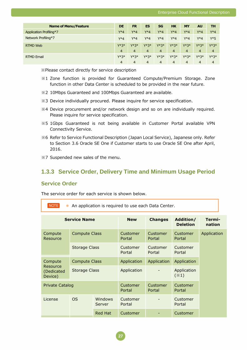
Name of Menu/Feature DE FR ES SG HK MY AU TH
Application Profiling*7 Y*4 Y*4 Y*4 Y*4 Y*4 Y*4 Y*4 Y*4
Network Profiling*7 Y*4 Y*4 Y*4 Y*4 Y*4 Y*4 Y*4 Y*5
RTMD Web Y*3*
4
Y*3*
4
Y*3*
4
Y*3*
4
Y*3*
4
Y*3*
4
Y*3*
4
Y*3*
4
RTMD Email Y*3*
4
Y*3*
4
Y*3*
4
Y*3*
4
Y*3*
4
Y*3*
4
Y*3*
4
Y*3*
4
※Please contact directly for service description
※1 Zone function is provided for Guaranteed Compute/Premium Storage. Zone
function in other Data Center is scheduled to be provided in the near future.
※2 10Mbps Guaranteed and 100Mbps Guaranteed are available.
※3 Device individually procured. Please inquire for service specification.
※4 Device procurement and/or network design and so on are individually required.
Please inquire for service specification.
※5 1Gbps Guaranteed is not being available in Customer Portal available VPN
Connectivity Service.
※6 Refer to Service Functional Description (Japan Local Service), Japanese only. Refer
to Section 3.6 Oracle SE One if Customer starts to use Oracle SE One after April,
2016.
※7 Suspended new sales of the menu.
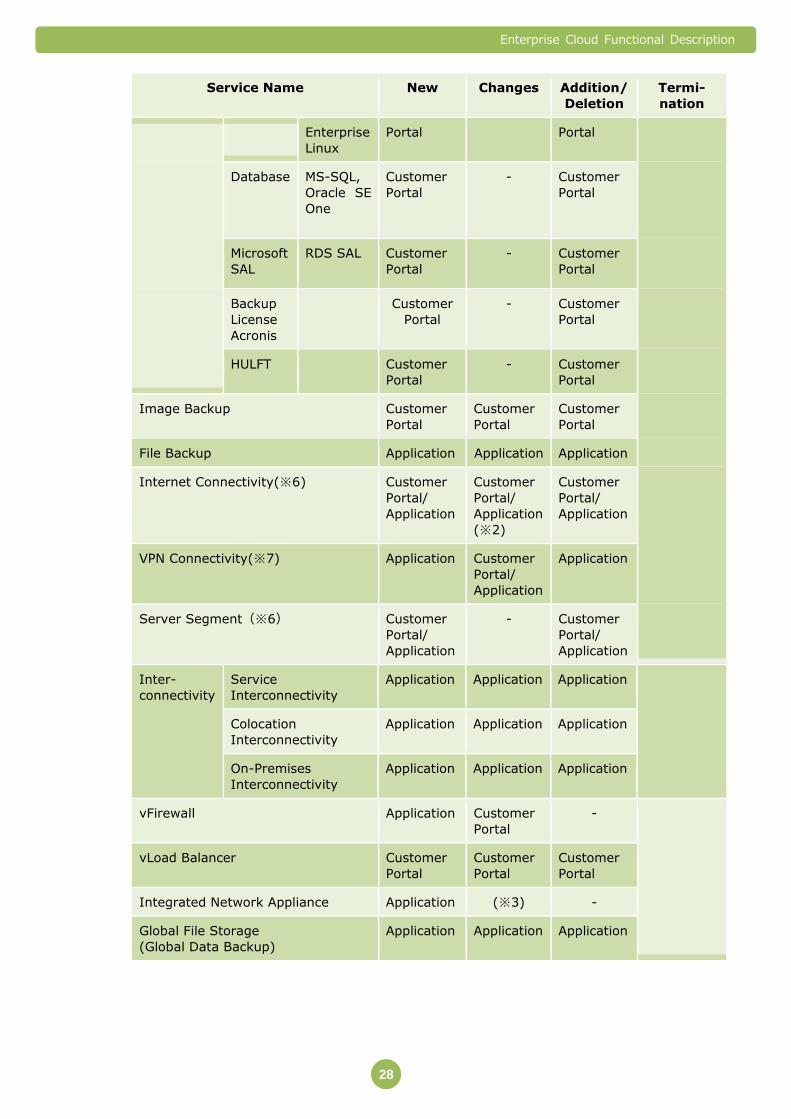
Service Order, Delivery Time and Minimum Usage Period 1.3.3
Service Order
The service order for each service is shown below.
An application is required to use each Data Center.
Service Name New Changes Addition/
Deletion
Termi-
nation
Compute
Resource
Compute Class Customer
Portal
Customer
Portal
Customer
Portal
Application
Storage Class Customer
Portal
Customer
Portal
Customer
Portal
Compute
Resource
(Dedicated
Device)
Compute Class Application Application Application
Storage Class Application - Application
(※1)
Private Catalog Customer
Portal
Customer
Portal
Customer
Portal
License OS Windows
Server
Customer
Portal
- Customer
Portal
Red Hat Customer - Customer
Enterprise Cloud Functional Description
28
Service Name New Changes Addition/
Deletion
Termi-
nation
Enterprise
Linux
Portal Portal
Database MS-SQL,
Oracle SE
One
Customer
Portal
- Customer
Portal
Microsoft
SAL
RDS SAL Customer
Portal
- Customer
Portal
Backup
License
Acronis
Customer
Portal
- Customer
Portal
HULFT Customer
Portal
- Customer
Portal
Image Backup Customer
Portal
Customer
Portal
Customer
Portal
File Backup Application Application Application
Internet Connectivity(※6) Customer
Portal/
Application
Customer
Portal/
Application
(※2)
Customer
Portal/
Application
VPN Connectivity(※7) Application Customer
Portal/
Application
Application
Server Segment(※6) Customer
Portal/
Application
-
Customer
Portal/
Application
Inter-
connectivity
Service
Interconnectivity
Application Application Application
Colocation
Interconnectivity
Application Application Application
On-Premises
Interconnectivity
Application Application Application
vFirewall Application Customer
Portal
-
vLoad Balancer Customer
Portal
Customer
Portal
Customer
Portal
Integrated Network Appliance Application (※3) -
Global File Storage
(Global Data Backup)
Application Application Application
Enterprise Cloud Functional Description
29
Service Name New Changes Addition/
Deletion
Termi-
nation
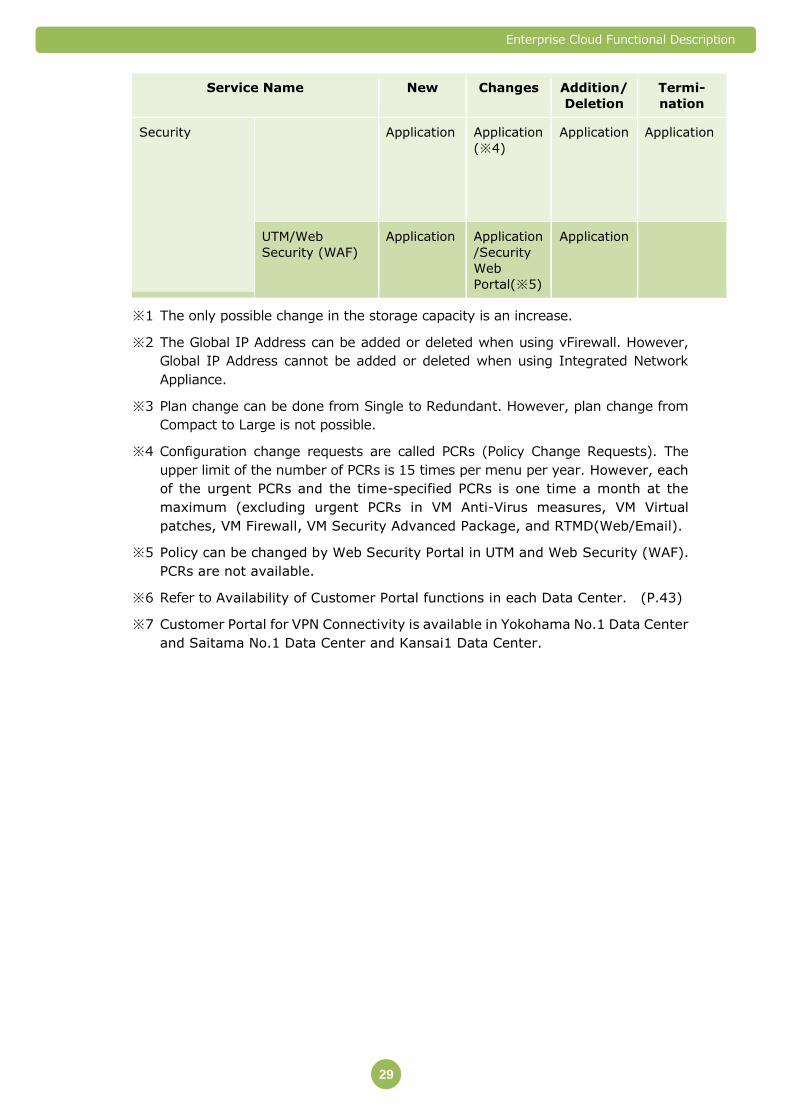
Security Application Application
(※4)
Application Application
UTM/Web
Security (WAF)
Application Application
/Security
Web
Portal(※5)
Application
※1 The only possible change in the storage capacity is an increase.
※2 The Global IP Address can be added or deleted when using vFirewall. However,
Global IP Address cannot be added or deleted when using Integrated Network
Appliance.
※3 Plan change can be done from Single to Redundant. However, plan change from
Compact to Large is not possible.
※4 Configuration change requests are called PCRs (Policy Change Requests). The
upper limit of the number of PCRs is 15 times per menu per year. However, each
of the urgent PCRs and the time-specified PCRs is one time a month at the
maximum (excluding urgent PCRs in VM Anti-Virus measures, VM Virtual
patches, VM Firewall, VM Security Advanced Package, and RTMD(Web/Email).
※5 Policy can be changed by Web Security Portal in UTM and Web Security (WAF).
PCRs are not available.
※6 Refer to Availability of Customer Portal functions in each Data Center. (P.43)
※7 Customer Portal for VPN Connectivity is available in Yokohama No.1 Data Center
and Saitama No.1 Data Center and Kansai1 Data Center.

Enterprise Cloud Functional Description
30
Standard Delivery Time
Please contact your local sales representative for details.
Minimum Usage Period
The minimum usage period is one month from the time that you start using
Enterprise Cloud.
However, minimum usage periods for the following service menus are specified
separately.
Service Name Minimum Usage Period
Compute Resource (Dedicated Device) 1 year
Resource Contract Conditions and Service Combination 1.3.4
Conditions
Resource Contract Conditions
The following resource contracts are required for each Data Center.
vFirewall/Integrated
Network Appliance
A contract for either one of the menu is mandatory.
Customer cannot have a contract for both.
You can only contract for one Internet Connectivity and one VPN
Connectivity for each Data Center that you are using.
Enterprise Cloud Functional Description
31
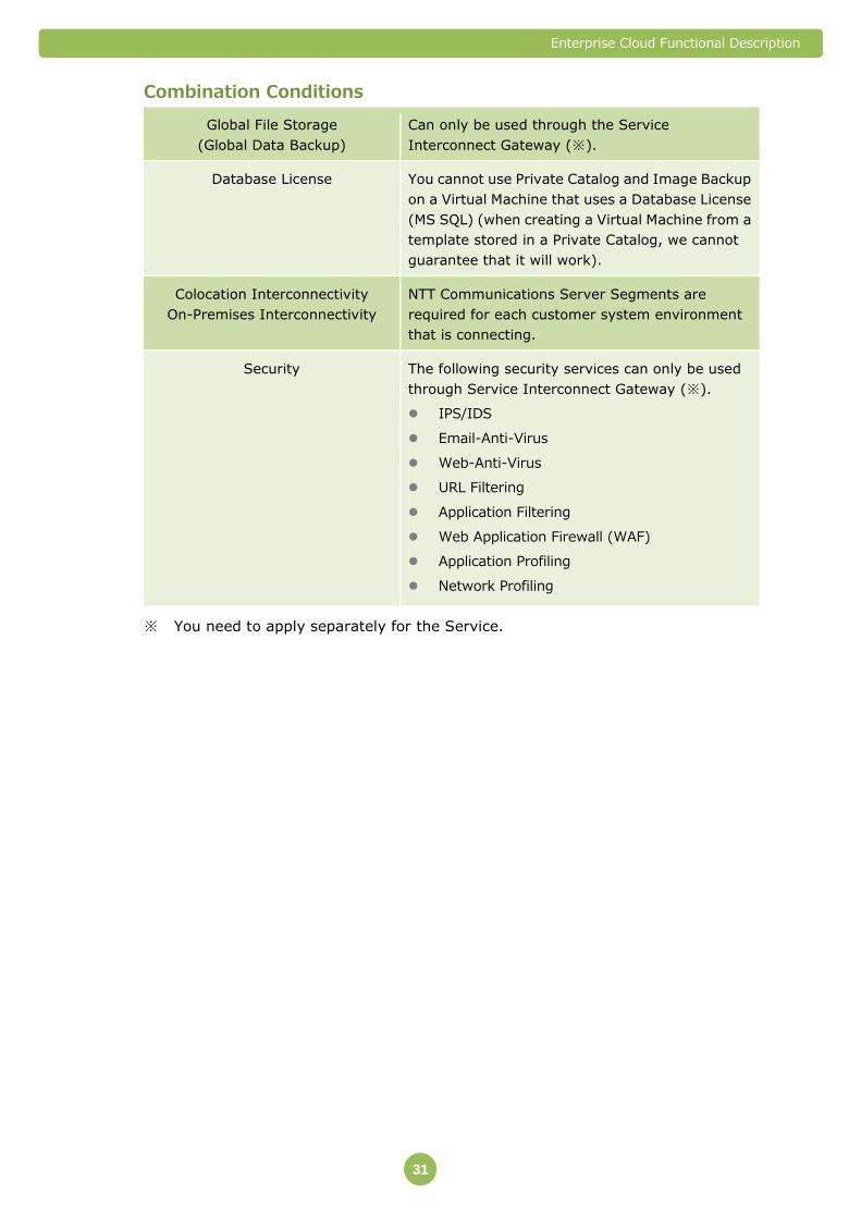
Combination Conditions
Global File Storage
(Global Data Backup)
Can only be used through the Service
Interconnect Gateway (※).
Database License You cannot use Private Catalog and Image Backup
on a Virtual Machine that uses a Database License
(MS SQL) (when creating a Virtual Machine from a
template stored in a Private Catalog, we cannot
guarantee that it will work).
Colocation Interconnectivity
On-Premises Interconnectivity
NTT Communications Server Segments are
required for each customer system environment
that is connecting.
Security The following security services can only be used
through Service Interconnect Gateway (※).
IPS/IDS
Email-Anti-Virus
Web-Anti-Virus
URL Filtering
Application Filtering
Web Application Firewall (WAF)
Application Profiling
Network Profiling
※ You need to apply separately for the Service.
Enterprise Cloud Functional Description
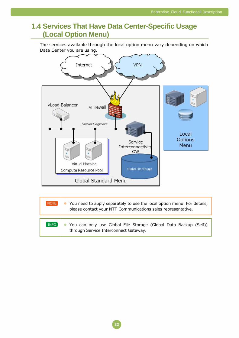
32
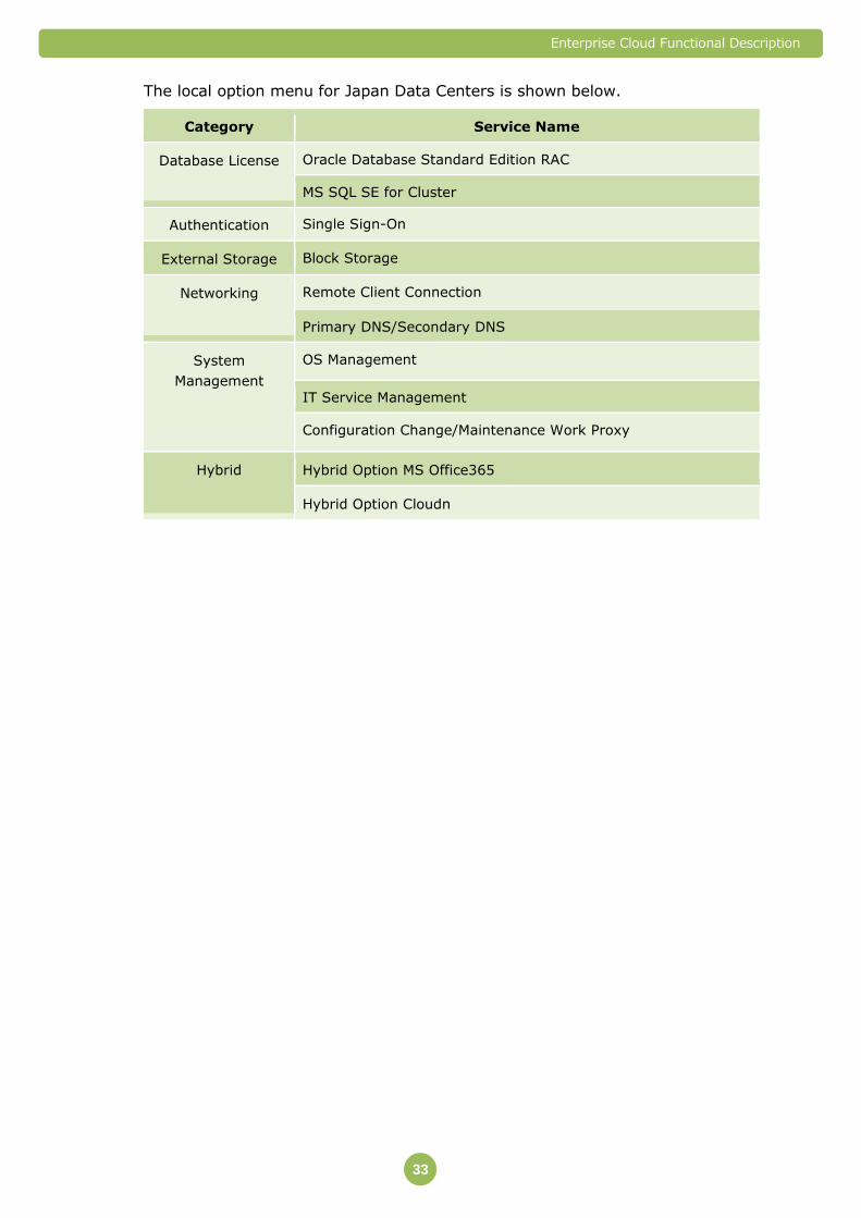
1.4 Services That Have Data Center-Specific Usage (Local Option Menu)
The services available through the local option menu vary depending on which
Data Center you are using.
You need to apply separately to use the local option menu. For details,
please contact your NTT Communications sales representative.
You can only use Global File Storage (Global Data Backup (Self))
through Service Interconnect Gateway.
Enterprise Cloud Functional Description
33
The local option menu for Japan Data Centers is shown below.
Category Service Name
Database License Oracle Database Standard Edition RAC
MS SQL SE for Cluster
Authentication Single Sign-On
External Storage Block Storage
Networking Remote Client Connection
Primary DNS/Secondary DNS
System
Management
OS Management
IT Service Management
Configuration Change/Maintenance Work Proxy
Hybrid Hybrid Option MS Office365
Hybrid Option Cloudn
Enterprise Cloud Functional Description
34
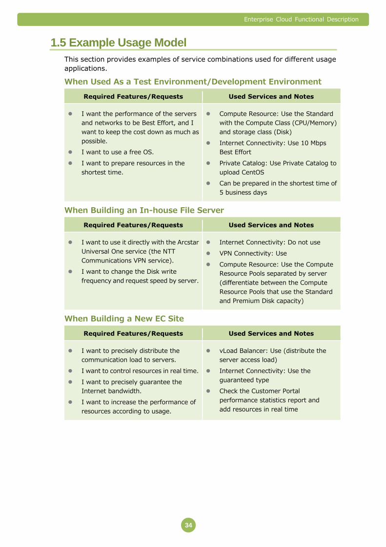
1.5 Example Usage Model
This section provides examples of service combinations used for different usage
applications.
When Used As a Test Environment/Development Environment
Required Features/Requests Used Services and Notes
I want the performance of the servers
and networks to be Best Effort, and I
want to keep the cost down as much as
possible.
I want to use a free OS.
I want to prepare resources in the
shortest time.
Compute Resource: Use the Standard
with the Compute Class (CPU/Memory)
and storage class (Disk)
Internet Connectivity: Use 10 Mbps
Best Effort
Private Catalog: Use Private Catalog to
upload CentOS
Can be prepared in the shortest time of
5 business days
When Building an In-house File Server
Required Features/Requests Used Services and Notes
I want to use it directly with the Arcstar
Universal One service (the NTT
Communications VPN service).
I want to change the Disk write
frequency and request speed by server.
Internet Connectivity: Do not use
VPN Connectivity: Use
Compute Resource: Use the Compute
Resource Pools separated by server
(differentiate between the Compute
Resource Pools that use the Standard
and Premium Disk capacity)
When Building a New EC Site
Required Features/Requests Used Services and Notes
I want to precisely distribute the
communication load to servers.
I want to control resources in real time.
I want to precisely guarantee the
Internet bandwidth.
I want to increase the performance of
resources according to usage.
vLoad Balancer: Use (distribute the
server access load)
Internet Connectivity: Use the
guaranteed type
Check the Customer Portal
performance statistics report and
add resources in real time
Enterprise Cloud Functional Description
35
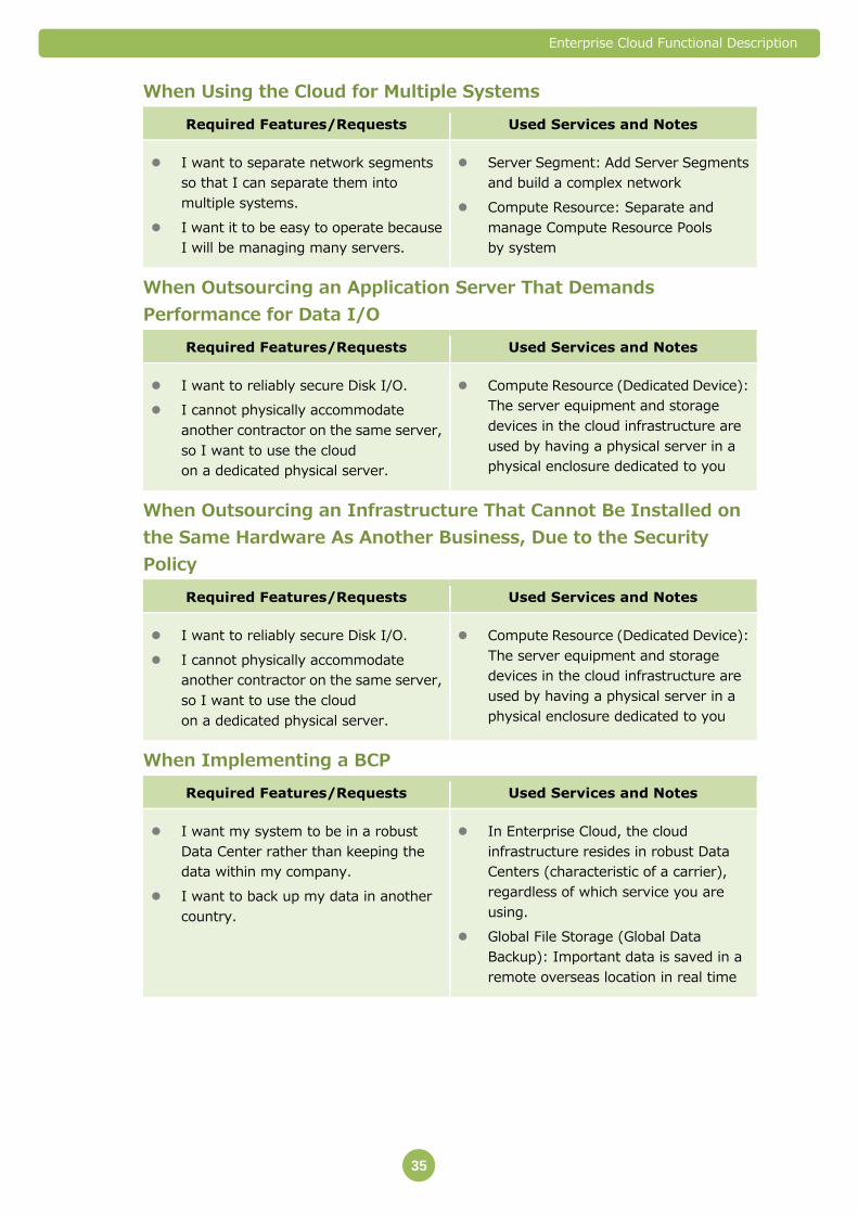
When Using the Cloud for Multiple Systems
Required Features/Requests Used Services and Notes
I want to separate network segments
so that I can separate them into
multiple systems.
I want it to be easy to operate because
I will be managing many servers.
Server Segment: Add Server Segments
and build a complex network
Compute Resource: Separate and
manage Compute Resource Pools
by system
When Outsourcing an Application Server That Demands
Performance for Data I/O
Required Features/Requests Used Services and Notes
I want to reliably secure Disk I/O.
I cannot physically accommodate
another contractor on the same server,
so I want to use the cloud
on a dedicated physical server.
Compute Resource (Dedicated Device):
The server equipment and storage
devices in the cloud infrastructure are
used by having a physical server in a
physical enclosure dedicated to you
When Outsourcing an Infrastructure That Cannot Be Installed on
the Same Hardware As Another Business, Due to the Security
Policy
Required Features/Requests Used Services and Notes
I want to reliably secure Disk I/O.
I cannot physically accommodate
another contractor on the same server,
so I want to use the cloud
on a dedicated physical server.
Compute Resource (Dedicated Device):
The server equipment and storage
devices in the cloud infrastructure are
used by having a physical server in a
physical enclosure dedicated to you
When Implementing a BCP
Required Features/Requests Used Services and Notes
I want my system to be in a robust
Data Center rather than keeping the
data within my company.
I want to back up my data in another
country.
In Enterprise Cloud, the cloud
infrastructure resides in robust Data
Centers (characteristic of a carrier),
regardless of which service you are
using.
Global File Storage (Global Data
Backup): Important data is saved in a
remote overseas location in real time
Enterprise Cloud Functional Description
36
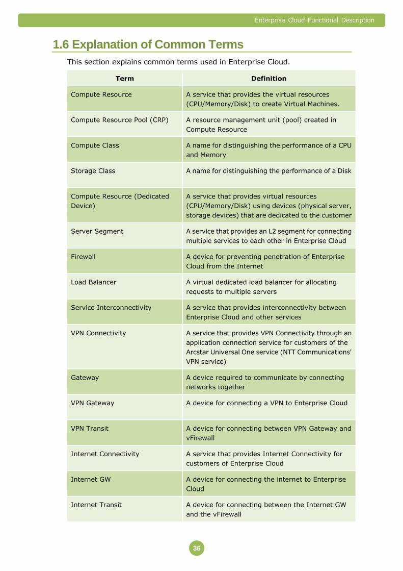
1.6 Explanation of Common Terms
This section explains common terms used in Enterprise Cloud.
Term Definition
Compute Resource
A service that provides the virtual resources
(CPU/Memory/Disk) to create Virtual Machines.
Compute Resource Pool (CRP)
A resource management unit (pool) created in
Compute Resource
Compute Class
A name for distinguishing the performance of a CPU
and Memory
Storage Class
A name for distinguishing the performance of a Disk
Compute Resource (Dedicated
Device)
A service that provides virtual resources
(CPU/Memory/Disk) using devices (physical server,
storage devices) that are dedicated to the customer
Server Segment
A service that provides an L2 segment for connecting
multiple services to each other in Enterprise Cloud
Firewall
A device for preventing penetration of Enterprise
Cloud from the Internet
Load Balancer
A virtual dedicated load balancer for allocating
requests to multiple servers
Service Interconnectivity
A service that provides interconnectivity between
Enterprise Cloud and other services
VPN Connectivity
A service that provides VPN Connectivity through an
application connection service for customers of the
Arcstar Universal One service (NTT Communications'
VPN service)
Gateway
A device required to communicate by connecting
networks together
VPN Gateway
A device for connecting a VPN to Enterprise Cloud
VPN Transit
A device for connecting between VPN Gateway and
vFirewall
Internet Connectivity
A service that provides Internet Connectivity for
customers of Enterprise Cloud
Internet GW
A device for connecting the internet to Enterprise
Cloud
Internet Transit
A device for connecting between the Internet GW
and the vFirewall
Enterprise Cloud Functional Description
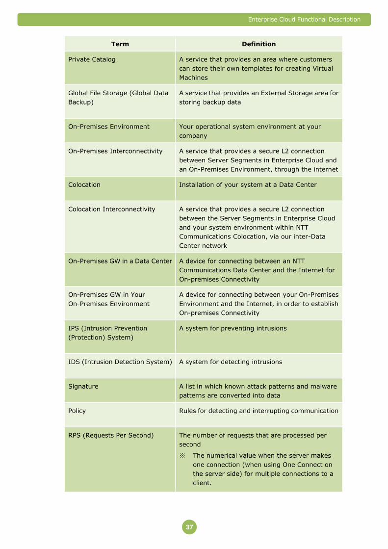
37
Term Definition
Private Catalog
A service that provides an area where customers
can store their own templates for creating Virtual
Machines
Global File Storage (Global Data
Backup)
A service that provides an External Storage area for
storing backup data
On-Premises Environment
Your operational system environment at your
company
On-Premises Interconnectivity
A service that provides a secure L2 connection
between Server Segments in Enterprise Cloud and
an On-Premises Environment, through the internet
Colocation
Installation of your system at a Data Center
Colocation Interconnectivity
A service that provides a secure L2 connection
between the Server Segments in Enterprise Cloud
and your system environment within NTT
Communications Colocation, via our inter-Data
Center network
On-Premises GW in a Data Center
A device for connecting between an NTT
Communications Data Center and the Internet for
On-premises Connectivity
On-Premises GW in Your
On-Premises Environment
A device for connecting between your On-Premises
Environment and the Internet, in order to establish
On-premises Connectivity
IPS (Intrusion Prevention
(Protection) System)
A system for preventing intrusions
IDS (Intrusion Detection System)
A system for detecting intrusions
Signature
A list in which known attack patterns and malware
patterns are converted into data
Policy
Rules for detecting and interrupting communication
RPS (Requests Per Second)
The number of requests that are processed per
second
※ The numerical value when the server makes
one connection (when using One Connect on
the server side) for multiple connections to a
client.
Enterprise Cloud Functional Description
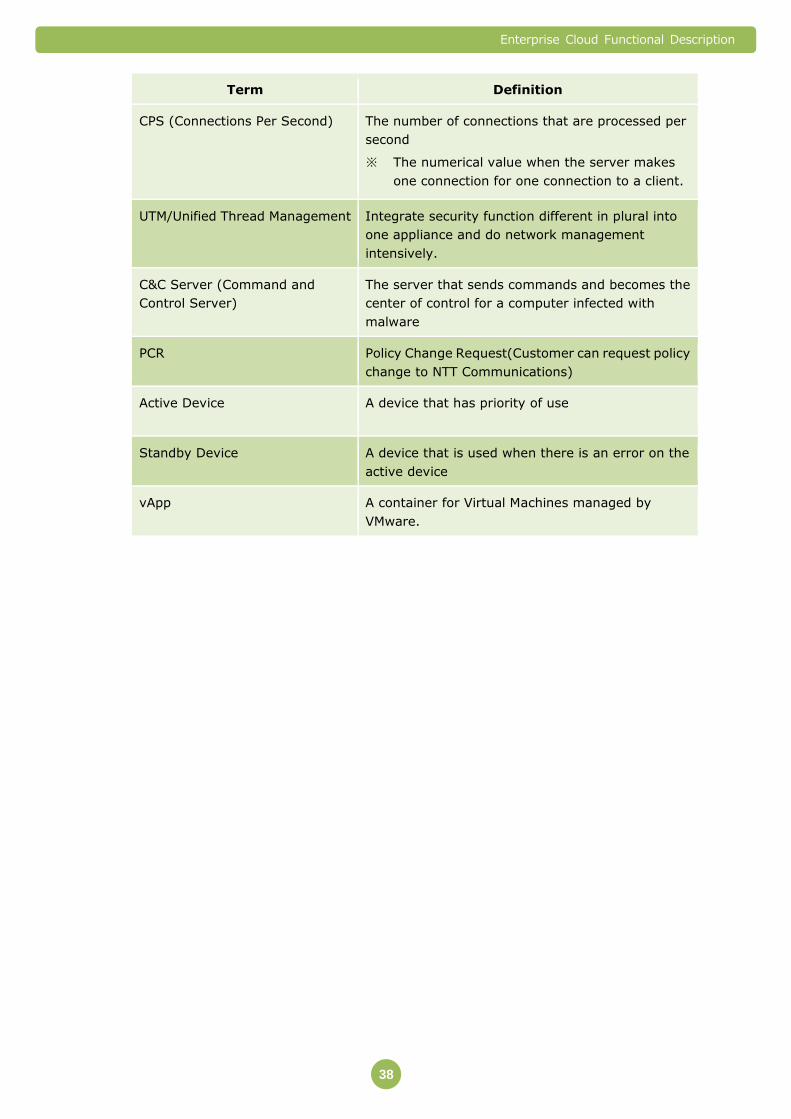
38
Term Definition
CPS (Connections Per Second)
The number of connections that are processed per
second
※ The numerical value when the server makes
one connection for one connection to a client.
UTM/Unified Thread Management Integrate security function different in plural into
one appliance and do network management
intensively.
C&C Server (Command and
Control Server)
The server that sends commands and becomes the
center of control for a computer infected with
malware
PCR
Policy Change Request(Customer can request policy
change to NTT Communications)
Active Device
A device that has priority of use
Standby Device
A device that is used when there is an error on the
active device
vApp A container for Virtual Machines managed by
VMware.

Enterprise Cloud Functional Description
39
1.7 Restrictions
Customers cannot enter the hosting room in which the servers and other equipment
provided by Enterprise Cloud are housed. All system construction work that you
perform should be performed remotely.
The common conditions for providing Enterprise Cloud, and service specifications
and the conditions for providing each service may change without notice.
When a contract or service is removed or canceled, or when you delete a service
from the Customer Portal, the data will be erased according to the method specified
by NTT Communications. A data erasure certificate is not issued.
When you use Enterprise Cloud, you must comply with the laws of foreign countries
and international trade and other Japanese import and export regulations, along
with all applicable laws and regulations related to importing, reimporting, exporting,
and reporting to and from other countries and regions. In other words, you are
solely responsible for compliance with laws and regulations related to all actions that
are taken when using Enterprise Cloud, such as transferring, processing, and
providing content.
You may not use Enterprise Cloud for the development, production, or use of
conventional weapons or weapons of mass destruction including nuclear weapons,
as stipulated in the Foreign Exchange and Foreign Trade Law and other Japanese
laws relating to exporting.
Enterprise Cloud Functional Description
40
2. Service Management (Portal Site)
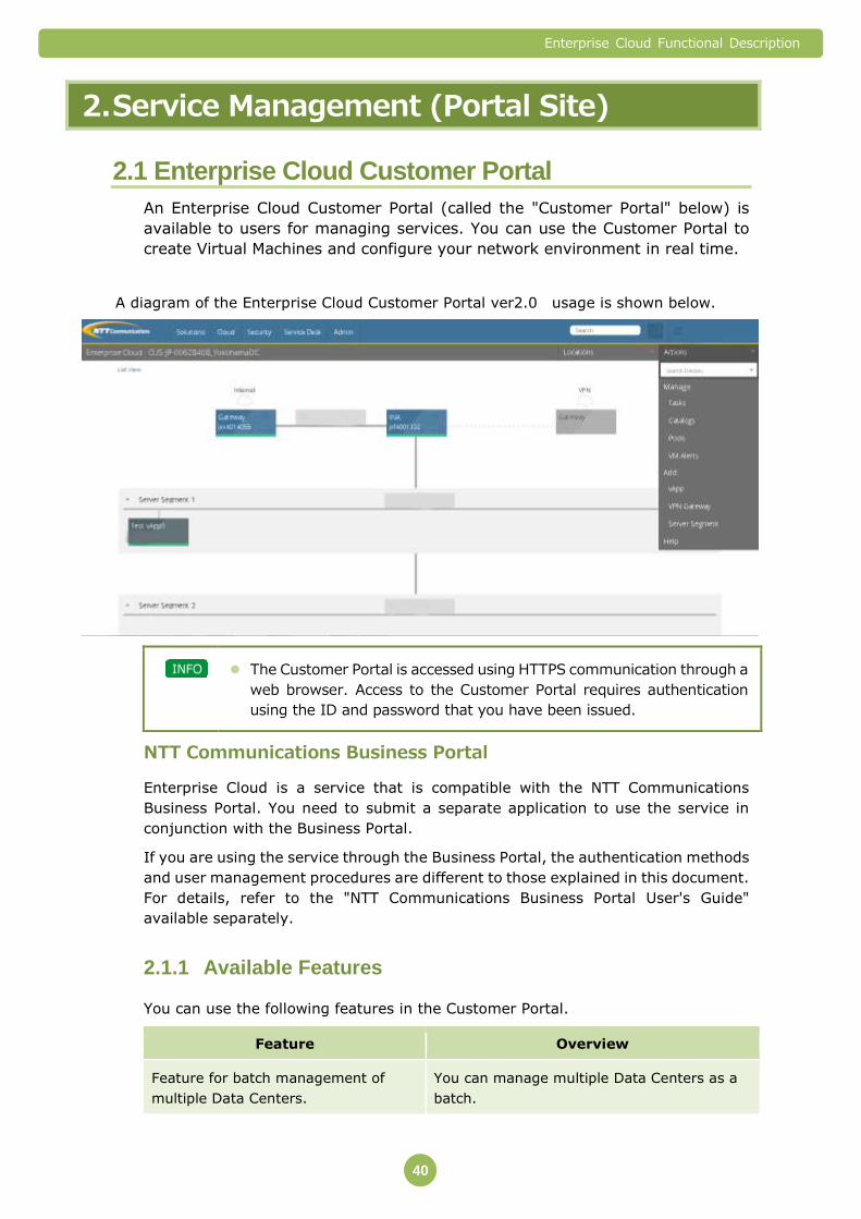
2.1 Enterprise Cloud Customer Portal
An Enterprise Cloud Customer Portal (called the "Customer Portal" below) is
available to users for managing services. You can use the Customer Portal to
create Virtual Machines and configure your network environment in real time.
A diagram of the Enterprise Cloud Customer Portal ver2.0 usage is shown below.
The Customer Portal is accessed using HTTPS communication through a
web browser. Access to the Customer Portal requires authentication
using the ID and password that you have been issued.
NTT Communications Business Portal
Enterprise Cloud is a service that is compatible with the NTT Communications
Business Portal. You need to submit a separate application to use the service in
conjunction with the Business Portal.
If you are using the service through the Business Portal, the authentication methods
and user management procedures are different to those explained in this document.
For details, refer to the "NTT Communications Business Portal User's Guide"
available separately.
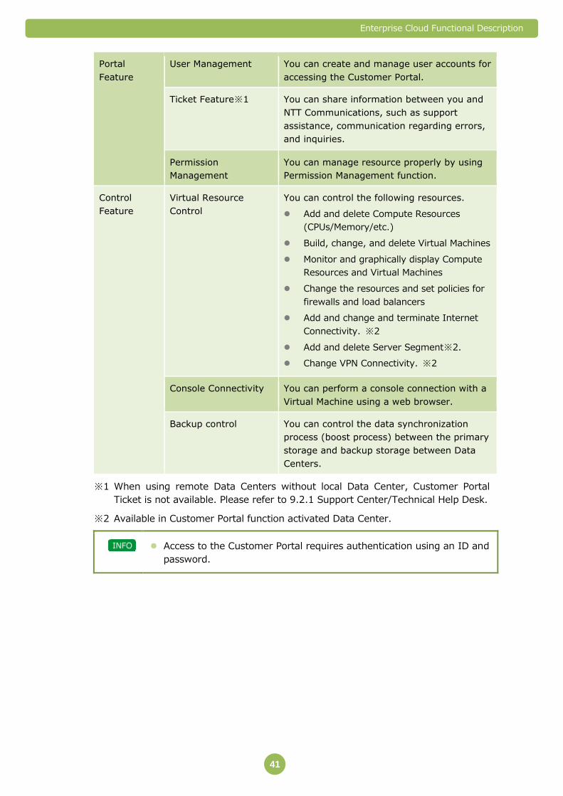
Available Features 2.1.1
You can use the following features in the Customer Portal.
Feature Overview
Feature for batch management of
multiple Data Centers.
You can manage multiple Data Centers as a
batch.
Enterprise Cloud Functional Description
41
Portal
Feature
User Management You can create and manage user accounts for
accessing the Customer Portal.
Ticket Feature※1 You can share information between you and
NTT Communications, such as support
assistance, communication regarding errors,
and inquiries.
Permission
Management
You can manage resource properly by using
Permission Management function.
Control
Feature
Virtual Resource
Control
You can control the following resources.
Add and delete Compute Resources
(CPUs/Memory/etc.)
Build, change, and delete Virtual Machines
Monitor and graphically display Compute
Resources and Virtual Machines
Change the resources and set policies for
firewalls and load balancers
Add and change and terminate Internet
Connectivity. ※2
Add and delete Server Segment※2.
Change VPN Connectivity. ※2
Console Connectivity You can perform a console connection with a
Virtual Machine using a web browser.
Backup control You can control the data synchronization
process (boost process) between the primary
storage and backup storage between Data
Centers.
※1 When using remote Data Centers without local Data Center, Customer Portal
Ticket is not available. Please refer to 9.2.1 Support Center/Technical Help Desk.
※2 Available in Customer Portal function activated Data Center.
Access to the Customer Portal requires authentication using an ID and
password.

Enterprise Cloud Functional Description
42
List of Items That Can Be Controlled 2.1.2
You can use the following operations in the Customer Portal.
Name of Menu/Feature Create/
Execute Display Change Delete
Compute Resource Pool
Compute Resource
CPU Y Y
Memory Y Y
Storage Y Y
Resource Pool Y Y Y Y
Monitoring Y
Public Catalog Virtual Machine Template/ vApp Template
Y
Private Catalog
Resource (Storage Capacity) Y Y Y Y
Template Y Y Y
Download Template Y
Take a Virtual Machine Template (OVA File)
Upload Y
Virtual Machine/vApp※4
Create a Virtual Machine/vApp
Private Catalog
Y
Use a Template
Public Catalog Y
Use a Template
Resource
vCPU Y Y
Memory Y Y
Number of Disks
Y Y Y
Disk Capacity Y Extension
vNIC (Select the Layout Segment)
Y Y
Powered On, Powered Off, Reset, Shutdown, Suspend, Restart
Y Y
Snapshot※5 Y Y
Console Connectivity Y Y
ISO Image Mount Feature Y
Install/Update VMware Guest Tools
Y
Set Guest Customization Enabled Y
Enable Windows OS SID Modification Feature
Y
Monitoring, Log Y
Image Backup Y Y Y Y
File Backup Y※1 Y Y Y
Internet Connectivity※2 Y Y Y Y
VPN Connectivity ※3
Bandwidth Y Y
Ping Y
Routing Information Y Y Y Y
Server Segment Segment Management※2 Y Y Y
IP Address Management Y Y Y
Interconnectivity Service Interconnectivity Y

Enterprise Cloud Functional Description
43
Name of Menu/Feature Create/
Execute Display Change Delete
Collocation Connectivity Y
Link
(On/Off),
VLAN
(Add/Delete)
vFirewall
vFirewall Installation (Required)
Network Configuration Y
Resource Level Y Y
Address or Object/Group Y Y Y Y
Service or Object/Group Y Y Y Y
Filtering Rules Y Y Y Y
NAT/NAPT Y Y Y Y
GIP Y
Routing Y Y Y Y
Performance Information Y
vLoad Balancer
vLoad Balancer Installation Y Y Y
Network Configuration Y
Resource Level Y Y
Contract Resources Y
Routing Y Y Y Y
Health Check Y Y Y Y
Real Server Settings Y Y Y Y
Server Group Settings Y Y Y Y
VIP Y Y Y Y
Monitoring Y Y Y Y
Global File Storage (Global Data Backup)
Disk Capacity Y
Boost Plan (S, M, L) Y
Boost Y Y Y Y
Replication Y Y Y Y
※1 File Backup Restore control is provided by the application installed in Virtual
Machine.
※2 The function is available on the Customer Portal the service released Data Center.
The number of Global IP address can be changed in case of using vFirewall.
※3 The function is available on the Customer Portal the service released Data Center.
※4 vApp is a new feature that can be seen on Customer Portal ver2.0 . vApp for
Enterprise Cloud can only support one single Virtual Machine.
※5 About availability in each Data Center, please refer to Section 3.1.6 Snapshot.
Enterprise Cloud Functional Description
44
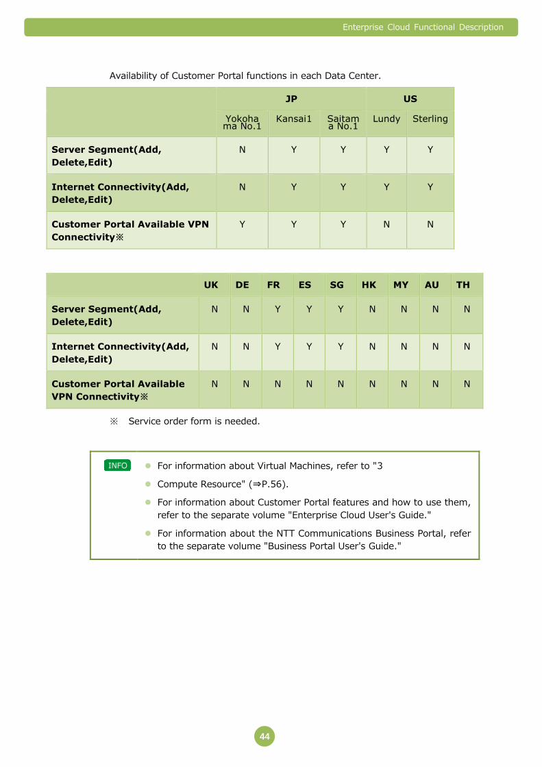
Availability of Customer Portal functions in each Data Center.
JP US
Yokohama No.1
Kansai1 Saitama No.1
Lundy Sterling
Server Segment(Add,
Delete,Edit)
N Y Y Y Y
Internet Connectivity(Add,
Delete,Edit)
N Y Y Y Y
Customer Portal Available VPN
Connectivity※
Y Y Y N N
UK DE FR ES SG HK MY AU TH
Server Segment(Add,
Delete,Edit)
N N Y Y Y N N N N
Internet Connectivity(Add,
Delete,Edit)
N N Y Y Y N N N N
Customer Portal Available
VPN Connectivity※
N N N N N N N N N
※ Service order form is needed.
For information about Virtual Machines, refer to "3
Compute Resource" (⇒P.56).
For information about Customer Portal features and how to use them,
refer to the separate volume "Enterprise Cloud User's Guide."
For information about the NTT Communications Business Portal, refer
to the separate volume "Business Portal User's Guide."
Enterprise Cloud Functional Description
45
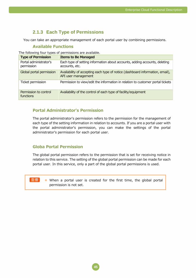
Each Type of Permissions 2.1.3
You can take an appropriate management of each portal user by combining permissions.
Available Functions
The following four types of permissions are available.
Type of Permission Items to Be Managed Portal administrator's permission
Each type of setting information about accounts, adding accounts, deleting accounts, etc.
Global portal permission Availability of accepting each type of notice (dashboard information, email), API user management
Ticket permission Permission to view/edit the information in relation to customer portal tickets
Permission to control functions
Availability of the control of each type of facility/equipment
Portal Administrator's Permission
The portal administrator's permission refers to the permission for the management of
each type of the setting information in relation to accounts. If you are a portal user with
the portal administrator's permission, you can make the settings of the portal
administrator's permission for each portal user.
Globa Portal Permission
The global portal permission refers to the permission that is set for receiving notice in
relation to this service. The setting of the global portal permission can be made for each
portal user. In this service, only a part of the global portal permissions is used.
When a portal user is created for the first time, the global portal
permission is not set.

Enterprise Cloud Functional Description
46
The following table shows the types of the notices with their summary as well as their availability in this
service.
Global Portal Permission Summary
Manage API User Can manage API users
Receive Maintenance Email Receives the notification in relation to maintenance
Receive Outage Email Receives the notification in relation to service troubles
Receive Marketing Email Receives the notification in relation marketing and the
update information about documents
Receive Security Email Receives the notification in relation to security
*Some permissions other than the above are displayed at the portal. They are not used in this service.
Ticket Permission
With the ticket permission, you can set the permission to view and the permission to
edit the tickets to each data center. The portal users that belong to the ticket
permission group can make the portal operations in relation to tickets within the scope
of the privilege assigned to the ticket permission group. To set up a permission, you
need to be a portal user that has a "portal administrator's permission" in the global
ticket permission.
If you add a new portal user, periodical batch processing links the
information to the ticket system. After you add a portal user to the
ticket permission group, if you do not see the user newly added, wait for
a while and make the setting.
In the ticket group, a group named "Automatic Group – Full Ticketing
Permissions" is registered as default. This group is the user group that
is assigned with the permissions to control all functions. This group is
not allowed to make any operation other than adding or deleting
portal users who belong to the group (editing ID names and/or
description and deleting user groups).
Permission to Control Function
The permission to control function refers to the permission to control the operation of
each of the facility and equipment.
On the Customer Portal, you can assign the permissions to control each function by the
unit of every one of the facility and equipment with respect to each user group. For
example, you can assign a permission for the control to every virtual server.

Enterprise Cloud Functional Description
47
The portal users that belong to the user group assigned with a permission to control the
functions of each of the facility and equipment can control each of the facility and
equipment with the assigned permission.
Details of the Permission
You can set up a permission concerning "View", "Edit (2.0)", and "Alarm" of each of the
facility and equipment.
Classification Description View The permission to view the setting information about facility and
equipment.
Edit (CP2.0) The permission to edit the setting information about facility and equipment (changing and deleting settings).
Add (CP2.0) The permission to add the setting information about facility and equipment.
Alarm The permission to receive the alert mail concerning facility and equipment.
Besides the permission to control the functions concerning each of the existing facility
and equipment, you can set up the default permission to control functions that is
automatically assigned to each of the new creation of facility and equipment. You can
assign the permission to control functions to each user group depending on the
requirements of the customer. A portal user needs to have the permission of a portal
administrator to make this operation. If a portal user belongs to two or more user
groups, the portal user is assigned with all the permissions to control the functions
assigned to the group he/she belong to.
It is necessary that a permission to control functions should be implemented in the unit
of the Area to which the Data Center belongs. If you do not have any such contract, you
do not need any such permission (they are not shown).
Shown below is some information about Areas.
Area Name of Data Center
Japan Yokohama No.1, Kansai1, Saitama No.1, Hong Kong Tai Po
Europe Hemel Hempstead2, Frankfurt2, Spain Madrid2, France Paris2
US San Jose Lundy, Virginia Sterling
APAC Singapore Serangoon, Malaysia Cyberjaya3, Thai Bangna, Australia Sydney1
In the user group, a group named "Automatic Group – Full
Permissions" is registered as default. This group is the user group that
is assigned with the permissions to control all functions. This group is
not allowed to make any operation other than adding or deleting
portal users who belong to the group (editing ID names and/or
description and deleting user groups).

Enterprise Cloud Functional Description
48
Included in the Permission
Shown below are the facility and equipment that can be assigned with the permissions to control
functions followed by their descriptions.
Classification Description Service Can add a permission to view/edit information about each service in the
contract. Enterprise Cloud Service Can add a permission to view/edit/add each type of resource to each
data center used in an individual Enterprise Cloud Service. Applicable items: To add a resource pool, add vApp add a private catalog, add vLoad Balancer, take management of an image backup, take management of a server segment
vFirewall Can add a permission to view/edit information about an individual vFirewall
vLoad Balancer Can add a permission to view/edit information about an individual vLoad Balancer
Integrated Network Appliance (INA)
Can add a permission to view/edit information about an individual Integrated Network Appliance
vApp (Virtual Machine) Can add a permission to view/edit information about an individual vApp (Virtual Machine)/to add a template and a permission for an alarm.
Virtual Machine Template Can add a permission to view/edit an individual Virtual Machine template.
Compute Resource Pool Can further add a permission to view/edit an individual Compute Resource Pool.
Private Catalog Can add a permission to view/edit an individual Private Catalog and a permission for vApp templates (ova format).
Colocation Interconnectivity Can add a permission to view/edit information about an individual colocation Interconnectivity gateway.
VPN Connectivity Can add a permission to view/edit information about an individual VPN gateway.
Internet Connectivity Can add a permission to view/edit information about an individual Internet gateway
There are some attentions in the services listed below.
Classification Description Image Backup The permission to the whole of the Image Backup (registering a backup
job, restoration, deleting a backup image): Included in the Enterprise Cloud Service. For an operation in relation to the backup of a server, however, the Edit (CP2.0) permission of each vApp is necessary. For receiving a notice in relation to a backup, it is necessary to check Edit (CP2.0) or Alert with vApp.
Server Segment Adding, deleting, and editing a Server Segment are included in the Enterprise Cloud Service. No display is available, and it is not possible to set up individual permissions of each segment.
Global File Storage Included in the service. This is displayed only when a contract is made.
Acronis license HULFT license DB license (Oracle SE/EE RAC) Power option※
It is not allowed to set up permissions. Customer who have view only permission account can manage the services.

Enterprise Cloud Functional Description
49
※ Available menus vary depending on the country of a contract and a data center. Currently,
as no permission function is available, the service is usable with an account of a view
permission. Permissions will be added in the future.
As the Customer Portal is updated to ver. 2.0, the "edit" permissions of
some services are subdivided into Edit (CP2.0) and Add xx (CP2.0).
Currently, "edit" works as a strong permission that includes the both.
So if you create a new group and set up the permissions, uncheck "edit"
and use only those permissions that are marked with "(CP2.0)".
Information about the indications on the Customer Portal and the description
Indication on the Portal
(Area)
Applicable Item
Item to Set Up Permissions
Description
Per Service Permissions
(Area)
Service in the contract
View The view permission in the Cloud, Colocation, Colocation Interconnectivity, and Global File Storage services
Edit The edit permission in the Cloud, Colocation, Colocation Interconnectivity, ad Global File Storage service
Alarm Not used.
Per Enterprise Cloud
Service Permissions
(Area)
Enterprise Cloud View The view permission at the Enterprise Cloud Portal
Edit *1 Not used.
Edit (CP2.0) The edit permission at the Enterprise Cloud Portal.
Add Compute Pool (CP2.0)
The permission to add Compute Pool
Add vApp (CP2.0) *2 The permission to add vApp (Virtual Machine)
Add Private Catalog (CP2.0)
The permission to add Private Catalog
Add vLB (CP2.0) The permission to add vLB
Alarm Not used.
Per Enterprise Cloud vFW Permissions
(Area)
vFirewall View The permission to view vFirewall
Edit *1 Not used.
Edit (CP2.0) The permission to edit vFirewall
Alarm Not used.
Per Enterprise Cloud vLB
Permissions (Area)
vLoad Balancer View The permission to view vLoad Balancer
Edit *1 Not used.
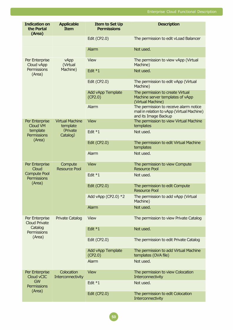
Enterprise Cloud Functional Description
50
Indication on the Portal
(Area)
Applicable Item
Item to Set Up Permissions
Description
Edit (CP2.0) The permission to edit vLoad Balancer
Alarm Not used.
Per Enterprise Cloud vApp Permissions
(Area)
vApp (Virtual
Machine)
View The permission to view vApp (Virtual Machine)
Edit *1 Not used.
Edit (CP2.0) The permission to edit vApp (Virtual Machine)
Add vApp Template (CP2.0)
The permission to create Virtual Machine server templates of vApp (Virtual Machine)
Alarm The permission to receive alarm notice mail in relation to vApp (Virtual Machine) and its Image Backup
Per Enterprise Cloud VM template
Permissions (Area)
Virtual Machine template (Private Catalog)
View The permission to view Virtual Machine templates
Edit *1 Not used.
Edit (CP2.0) The permission to edit Virtual Machine templates
Alarm Not used.
Per Enterprise Cloud
Compute Pool Permissions
(Area)
Compute Resource Pool
View The permission to view Compute Resource Pool
Edit *1 Not used.
Edit (CP2.0) The permission to edit Compute Resource Pool
Add vApp (CP2.0) *2 The permission to add vApp (Virtual Machine)
Alarm Not used.
Per Enterprise Cloud Private
Catalog Permissions
(Area)
Private Catalog View The permission to view Private Catalog
Edit *1 Not used.
Edit (CP2.0) The permission to edit Private Catalog
Add vApp Template (CP2.0)
The permission to add Virtual Machine templates (OVA file)
Alarm Not used.
Per Enterprise Cloud vCIC
GW Permissions
(Area)
Colocation Interconnectivity
View The permission to view Colocation Interconnectivity
Edit *1 Not used.
Edit (CP2.0) The permission to edit Colocation Interconnectivity

Enterprise Cloud Functional Description
51
Indication on the Portal
(Area)
Applicable Item
Item to Set Up Permissions
Description
Per Enterprise Cloud vVPN
GW Permissions
(Area)
VPN Connectivity
View The permission to view VPN Connectivity
Edit *1 Not used.
Edit (CP2.0) The permission to edit VPN Connectivity
Per Enterprise Cloud INA
Permissions (Area)
Integrated Network Appliance
View The permission to view INA
Edit *1 Not used.
Edit (CP2.0) The permission to edit INA
Alarm Not used.
Per Enterprise Cloud
vInternet GW Permissions
(Area)
Internet Connectivity
View The permission to view Internet Connectivity
Edit *1 Not used.
Edit (CP2.0) The permission to edit Internet Connectivity
*1. "Edit" is in the enabled status on the system as a permission similar to Edit (CP2.0) + Add (CP2.0).
So if you set up the permission, make sure uncheck it.
*2. If you add a permission of vApp (Virtual Machine), it is necessary to set up both Add vApp (CP2.0)
items of Enterprise Cloud and Compute Resource Pool.
* Alarms are valid only with vApp.
* Integrated Network Appliance and vFirewall are used in a service included in a contract.
* Some data centers may show "Per Enterprise Cloud vLB2 Permissions", but this is not used in this
service.
Important Points 2.1.4
The Customer Portal is accessed through a web browser using the Internet. Please
prepare an environment in which you have Internet access.
Use the following web browser to access the Customer Portal.
Mozilla Firefox 10 or higher 32bit
※ To use a console connection, you need Mozilla Firefox 11.0 or higher running
on Windows except version 8.
If Firefox version is 30 or higher, please change VMware Remote Console Plug-in
setting to be always activated.
Enterprise Cloud Functional Description
52
NTT Communications is not responsible for unauthorized use of the
Customer Portal resulting from the loss or leaking of password
information issued to the customer.
When using one Customer Portal to batch manage multiple Data
Centers, please notify NTT Communications beforehand. You cannot
consolidate Data Centers back into one Data Center after you start
using them in separate Customer Portals.
When using a console connection, enable the Java Script features in
your web browser.
You cannot manage one Data Center from multiple Customer Portals.
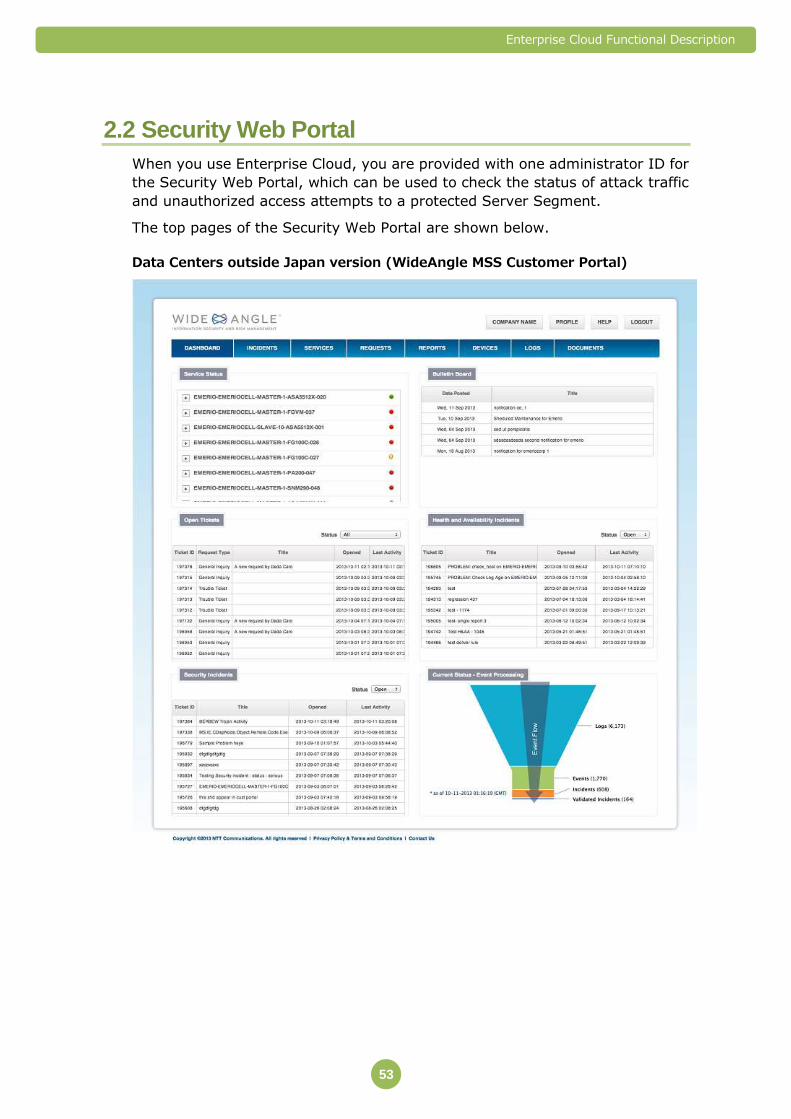
Enterprise Cloud Functional Description
53
2.2 Security Web Portal
When you use Enterprise Cloud, you are provided with one administrator ID for
the Security Web Portal, which can be used to check the status of attack traffic
and unauthorized access attempts to a protected Server Segment.
The top pages of the Security Web Portal are shown below.
Data Centers outside Japan version (WideAngle MSS Customer Portal)
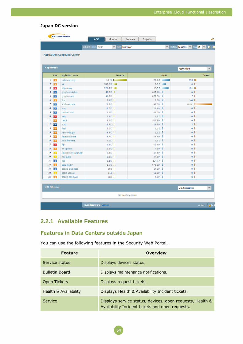
Enterprise Cloud Functional Description
54
Japan DC version
Available Features 2.2.1
Features in Data Centers outside Japan
You can use the following features in the Security Web Portal.
Feature Overview
Service status Displays devices status.
Bulletin Board Displays maintenance notifications.
Open Tickets Displays request tickets.
Health & Availability Displays Health & Availability Incident tickets.
Service Displays service status, devices, open requests, Health &
Availability Incident tickets and open requests.
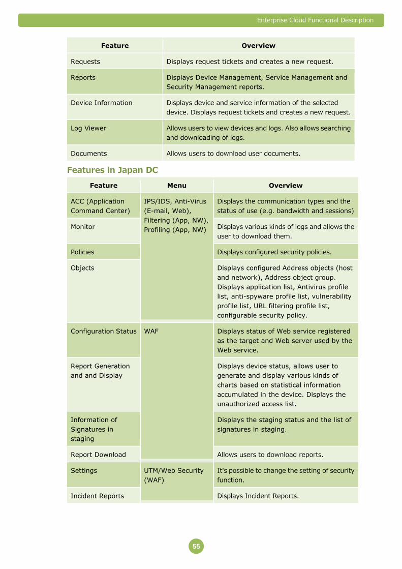
Enterprise Cloud Functional Description
55
Feature Overview
Requests Displays request tickets and creates a new request.
Reports Displays Device Management, Service Management and
Security Management reports.
Device Information Displays device and service information of the selected
device. Displays request tickets and creates a new request.
Log Viewer Allows users to view devices and logs. Also allows searching
and downloading of logs.
Documents Allows users to download user documents.
Features in Japan DC
Feature Menu Overview
ACC (Application
Command Center)
IPS/IDS, Anti-Virus
(E-mail, Web),
Filtering (App, NW),
Profiling (App, NW)
Displays the communication types and the
status of use (e.g. bandwidth and sessions)
Monitor Displays various kinds of logs and allows the
user to download them.
Policies Displays configured security policies.
Objects Displays configured Address objects (host
and network), Address object group.
Displays application list, Antivirus profile
list, anti-spyware profile list, vulnerability
profile list, URL filtering profile list,
configurable security policy.
Configuration Status WAF Displays status of Web service registered
as the target and Web server used by the
Web service.
Report Generation
and and Display
Displays device status, allows user to
generate and display various kinds of
charts based on statistical information
accumulated in the device. Displays the
unauthorized access list.
Information of
Signatures in
staging
Displays the staging status and the list of
signatures in staging.
Report Download Allows users to download reports.
Settings UTM/Web Security
(WAF)
It's possible to change the setting of security
function.
Incident Reports Displays Incident Reports.
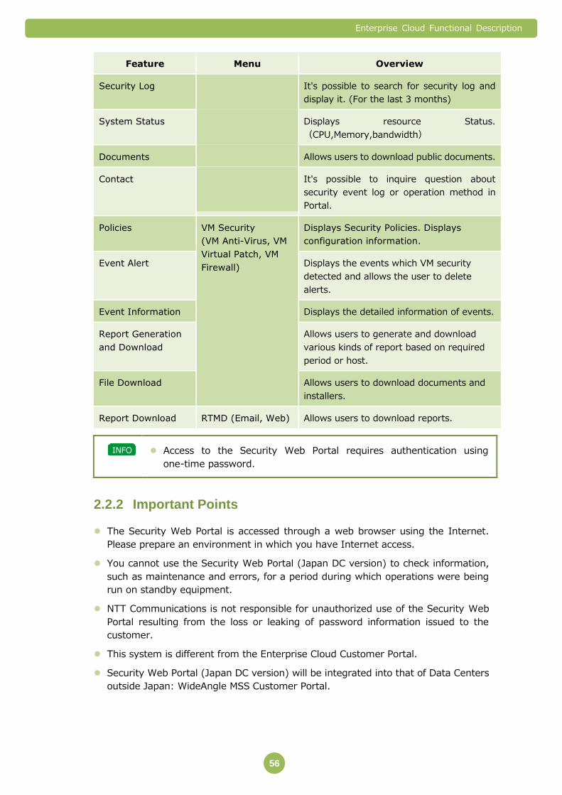
Enterprise Cloud Functional Description
56
Feature Menu Overview
Security Log It's possible to search for security log and
display it. (For the last 3 months)
System Status Displays resource Status.
(CPU,Memory,bandwidth)
Documents Allows users to download public documents.
Contact It's possible to inquire question about
security event log or operation method in
Portal.
Policies VM Security
(VM Anti-Virus, VM
Virtual Patch, VM
Firewall)
Displays Security Policies. Displays
configuration information.
Event Alert Displays the events which VM security
detected and allows the user to delete
alerts.
Event Information Displays the detailed information of events.
Report Generation
and Download
Allows users to generate and download
various kinds of report based on required
period or host.
File Download Allows users to download documents and
installers.
Report Download RTMD (Email, Web) Allows users to download reports.
Access to the Security Web Portal requires authentication using
one-time password.
Important Points 2.2.2
The Security Web Portal is accessed through a web browser using the Internet.
Please prepare an environment in which you have Internet access.
You cannot use the Security Web Portal (Japan DC version) to check information,
such as maintenance and errors, for a period during which operations were being
run on standby equipment.
NTT Communications is not responsible for unauthorized use of the Security Web
Portal resulting from the loss or leaking of password information issued to the
customer.
This system is different from the Enterprise Cloud Customer Portal.
Security Web Portal (Japan DC version) will be integrated into that of Data Centers
outside Japan: WideAngle MSS Customer Portal.

Enterprise Cloud Functional Description
57
3. Compute (Global Standard Menu)
3.1 Compute Resource
Compute Resource is a service that provides virtual equipment (Compute
Resources) by combining CPUs, Memory, and Disks to create Virtual Machines.
Compute Resources are provided by virtualizing physical servers and storage
devices shared by multiple users.
Use the Customer Portal to create, change, or delete a Virtual Machine.
Available Features 3.1.1
You can use the following features in Compute Resource.
Feature Overview
1 Provision of Compute
Resource Pools
A feature that uses the Compute Resources
(CPU/Memory/Disk) to create Virtual Machines.
You can create multiple machines.
2 Features for controlling
Compute Resource Pools
From the Customer Portal, you can perform the
following actions for Compute Resource Pools.
Add/reduce resources
Assign resources to a Virtual Machine
Add, delete, or change a Compute Resource Pool

Enterprise Cloud Functional Description
58
The infrastructure for Compute Resources is comprised of HA (High
Availability) clusters and storage devices that have spare physical
servers. If a failure is detected on a physical server that contains
Compute Resources, the server is automatically replaced by a standby
server.
You can select Compute Resources that offer the appropriate
performance level (Guaranteed, Premium, Standard) for your intended
use.
Provision of Compute Resource Pools 3.1.2
You can create and use multiple Compute Resource Pools (CPUs/Memory/Disk) to
create a Virtual Machine.
Use the Customer Portal to add, delete, and change Compute Resource Pools.
When using multiple Data Centers, there must be a Compute Resource
Pool for each Data Center.
Compute Resources (CPU/Memory/Disk) cannot be assigned to
multiple Compute Resource Pools.
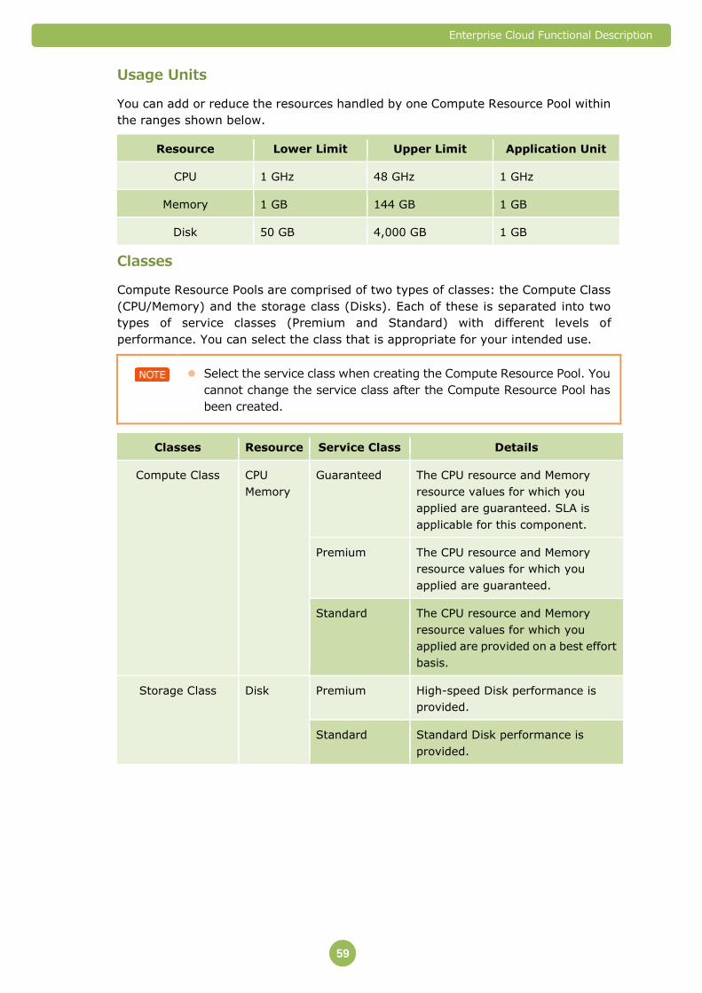
Enterprise Cloud Functional Description
59
Usage Units
You can add or reduce the resources handled by one Compute Resource Pool within
the ranges shown below.
Resource Lower Limit Upper Limit Application Unit
CPU 1 GHz 48 GHz 1 GHz
Memory 1 GB 144 GB 1 GB
Disk 50 GB 4,000 GB 1 GB
Classes
Compute Resource Pools are comprised of two types of classes: the Compute Class
(CPU/Memory) and the storage class (Disks). Each of these is separated into two
types of service classes (Premium and Standard) with different levels of
performance. You can select the class that is appropriate for your intended use.
Select the service class when creating the Compute Resource Pool. You
cannot change the service class after the Compute Resource Pool has
been created.
Classes Resource Service Class Details
Compute Class CPU
Memory
Guaranteed The CPU resource and Memory
resource values for which you
applied are guaranteed. SLA is
applicable for this component.
Premium The CPU resource and Memory
resource values for which you
applied are guaranteed.
Standard The CPU resource and Memory
resource values for which you
applied are provided on a best effort
basis.
Storage Class Disk Premium High-speed Disk performance is
provided.
Standard Standard Disk performance is
provided.
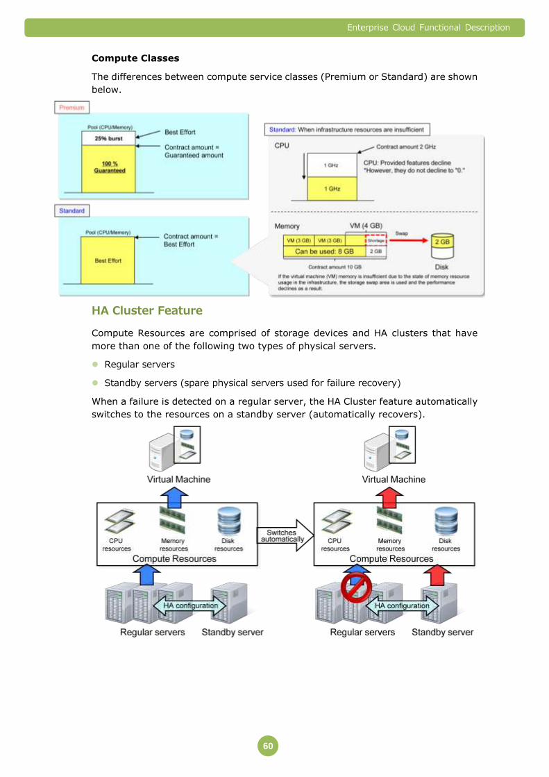
Enterprise Cloud Functional Description
60
Compute Classes
The differences between compute service classes (Premium or Standard) are shown
below.
HA Cluster Feature
Compute Resources are comprised of storage devices and HA clusters that have
more than one of the following two types of physical servers.
Regular servers
Standby servers (spare physical servers used for failure recovery)
When a failure is detected on a regular server, the HA Cluster feature automatically
switches to the resources on a standby server (automatically recovers).

Enterprise Cloud Functional Description
61
The HA Cluster feature does not detect any failures and perform an
automatic recovery on a Virtual Machine that you have created.
The HA Cluster feature does not guarantee the recovery of a Guest OS
or applications running on a Guest OS, on a Virtual Machine that you
have created.
Zones
When a failure is detected on a regular server, the Virtual Machine restarts on a
standby server. The Virtual Machine that you created may temporarily stop until it
restarts on the standby server.
As a result, if you have created a redundant configuration between multiple Virtual
Machines but you have added the Virtual Machines to the same Compute Resource
Pool, the redundant configuration may not behave as expected.
Zones are used to deal with this problem.
A zone is a group of physical equipment (physical servers and storage devices) that
accommodate a Compute Resource Pool. You can choose either Zone A or Zone B for
each Compute Resource Pool.
Virtual machines created from Compute Resource Pools with different zones run on
different physical equipment, as shown below.
Example: When zones are set on Compute Resource Pools 1 to 3
Compute Resource Pool Zone Virtual Machine Physical Equipment
Running the Virtual
Machine
Compute Resource Pool 1 Zone A Virtual Machine i Physical Equipment A
Virtual Machine ii Physical Equipment A
Virtual Machine iii Physical Equipment A
Compute Resource Pool 2 Zone A Virtual Machine Physical Equipment A
Compute Resource Pool 3 Zone B Virtual Machine Physical Equipment B
For information on Data Centers that offer zones, refer to "1.3.2
Available Data Centers" (⇒P. 22).
Zone function provides the availability of the physical serve that Virtual
Machine would run. It does not provide the availability for Network
devices.
Features for Controlling Compute Resource Pools 3.1.3
From the Customer Portal, you can perform the following actions for Compute
Resource Pools.
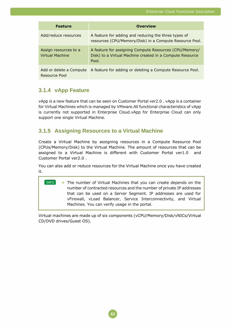
Enterprise Cloud Functional Description
62
Feature Overview
Add/reduce resources A feature for adding and reducing the three types of
resources (CPU/Memory/Disk) in a Compute Resource Pool.
Assign resources to a
Virtual Machine
A feature for assigning Compute Resources (CPU/Memory/
Disk) to a Virtual Machine created in a Compute Resource
Pool.
Add or delete a Compute
Resource Pool
A feature for adding or deleting a Compute Resource Pool.
vApp Feature 3.1.4
vApp is a new feature that can be seen on Customer Portal ver2.0 . vApp is a container
for Virtual Machines which is managed by VMware.All functional characteristics of vApp
is currently not supported in Enterprise Cloud.vApp for Enterprise Cloud can only
support one single Virtual Machine.
Assigning Resources to a Virtual Machine 3.1.5
Create a Virtual Machine by assigning resources in a Compute Resource Pool
(CPUs/Memory/Disk) to the Virtual Machine. The amount of resources that can be
assigned to a Virtual Machine is different with Customer Portal ver1.0 and
Customer Portal ver2.0 .
You can also add or reduce resources for the Virtual Machine once you have created
it.
The number of Virtual Machines that you can create depends on the
number of contracted resources and the number of private IP addresses
that can be used on a Server Segment. IP addresses are used for
vFirewall, vLoad Balancer, Service Interconnectivity, and Virtual
Machines. You can verify usage in the portal.
Virtual machines are made up of six components (vCPU/Memory/Disk/vNICs/Virtual
CD/DVD drives/Guest OS).

Enterprise Cloud Functional Description
63
Resources that can be assigned to a Virtual Machine (Customer Portal ver2.0 )
*The amount of resources that can be assigned to Virtual Machine differ according
to the Compute Class.
* The amount of vCPU, and Disk Capacity that could be assigned to each Virtual
Machine differ depending on the Compute Class. The total disk capacity that could be
assigned must be the amount which subtracts the memory capacity assigned to
Virtual Machine from the leftover disk capacity of Compute Resource Pool.
If the leftover of Storage Resource for Compute Resource Pool is
3,500GB, and 128GB memory is being mounted, the maximum of total
disk capacity is 3,372GB (= 3,500-128).
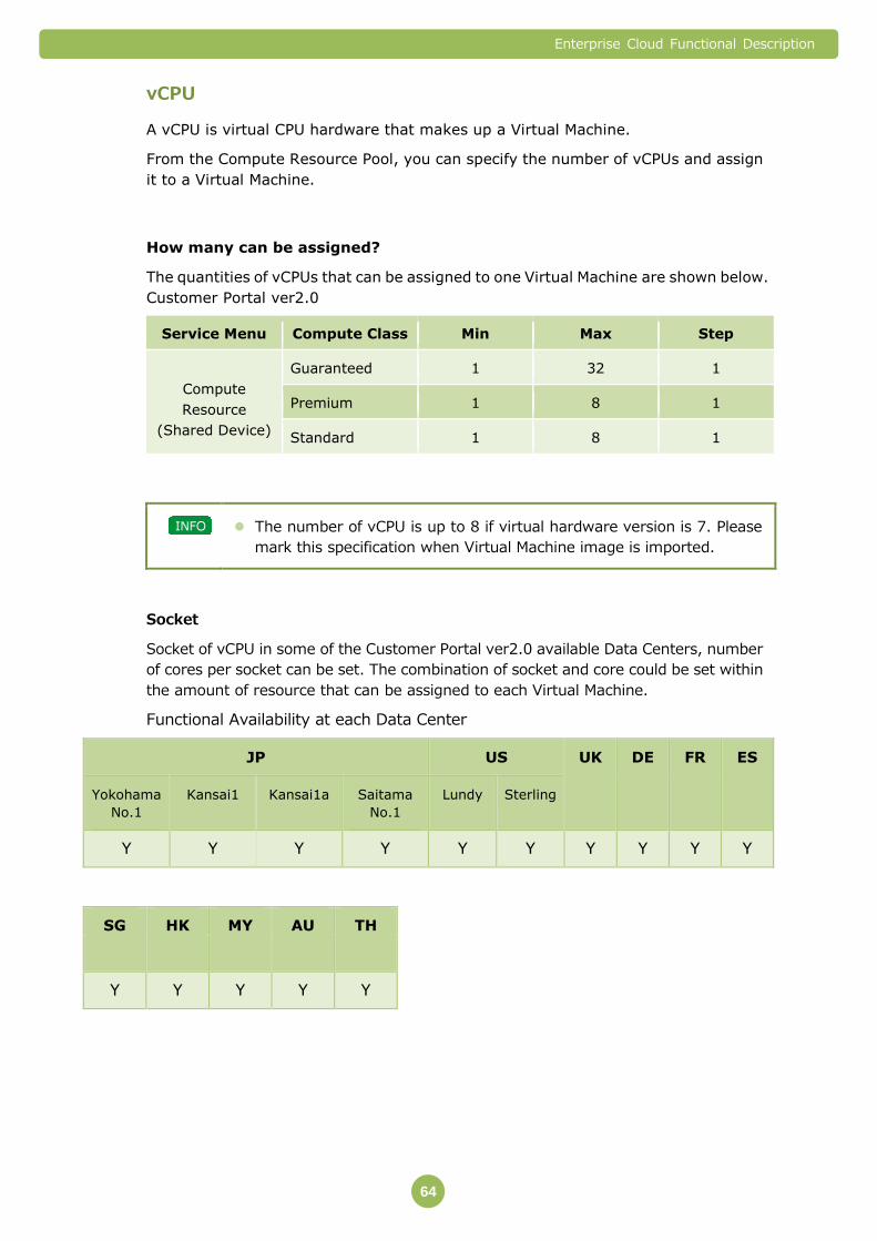
Enterprise Cloud Functional Description
64
vCPU
A vCPU is virtual CPU hardware that makes up a Virtual Machine.
From the Compute Resource Pool, you can specify the number of vCPUs and assign
it to a Virtual Machine.
How many can be assigned?
The quantities of vCPUs that can be assigned to one Virtual Machine are shown below.
Customer Portal ver2.0
Service Menu Compute Class Min Max Step
Compute
Resource
(Shared Device)
Guaranteed 1 32 1
Premium 1 8 1
Standard 1 8 1
The number of vCPU is up to 8 if virtual hardware version is 7. Please
mark this specification when Virtual Machine image is imported.
Socket
Socket of vCPU in some of the Customer Portal ver2.0 available Data Centers, number
of cores per socket can be set. The combination of socket and core could be set within
the amount of resource that can be assigned to each Virtual Machine.
Functional Availability at each Data Center
JP US UK DE FR ES
Yokohama
No.1
Kansai1 Kansai1a Saitama
No.1
Lundy Sterling
Y Y Y Y Y Y Y Y Y Y
SG HK MY AU TH
Y Y Y Y Y

Enterprise Cloud Functional Description
65
vCPU processing capacity
The vCPU processing capacity is different for each Data Center. The processing
capacity is the same as the physical processors listed in the table below.
Data Center Processor
Yokohama No.1 2010 Intel Xeon Processor (equivalent to a maximum of
2.5 GHz)
Kansai 1 2012 Intel Xeon Processor (equivalent to a maximum of
2.0 GHz)
Saitama No.1 2012 Intel Xeon Processor (equivalent to a maximum of
2.2GHz)
San Jose Lundy 2012 Intel Xeon Processor (equivalent to a maximum of
2.2 GHz)
Virginia Sterling 2012 Intel Xeon Processor (equivalent to a maximum of
2.2 GHz)
UK Hemel Hempstead2 2012 Intel Xeon Processor (equivalent to a maximum of
2.2 GHz)
Germany Frankfurt2 2012 Intel Xeon Processor (equivalent to a maximum of
2.2 GHz)
France Paris2 2012 Intel Xeon Processor (equivalent to a maximum of
2.2 GHz)
Spain Madrid2 2012 Intel Xeon Processor (equivalent to a maximum of
2.2 GHz)
Singapore Serangoon 2012 Intel Xeon Processor (equivalent to a maximum of
2.2 GHz)
Hong Kong Tai Po 2009 Intel Xeon Processor (equivalent to a maximum of
2.7 GHz)
Australia Sydney1 2012 Intel Xeon Processor (equivalent to a maximum of
2.2 GHz)
Thailand Bangna 2012 Intel Xeon Processor (equivalent to a maximum of
2.0 GHz)
You can only change the number of vCPUs when the Virtual Machine is
powered off. Please do not change configuration in Partially Powered
Off state.
Enterprise Cloud Functional Description
66
Data Center Processor
Malaysia Cyberjaya3 2012 Intel Xeon Processor (equivalent to a maximum of
2.2 GHz)
The vCPU processing power varies depending on the following
conditions. There is no guarantee that a vCPU will always operate at the
maximum processing capacity.
- When the total vCPU processing capacity for Virtual Machines
running in one Compute Resource Pool is more than the purchased
Compute Resource Pool (CPU resources)
- The load condition of the Guest OS on the Virtual Machine
Understanding resource consumption
The CPU resources that are consumed from the Compute Resource Pool are the
resources that are actually used by the Virtual Machine for computational
processing.
If a vCPU assigned to a Virtual Machine is not running, CPU resources
are not consumed from the Compute Resources.
If computational processing by a vCPU reaches the CPU upper limit for
the Compute Resource Pool for each Virtual Machine, the processing
capacity is averaged between the Virtual Machines and operations
continue.
Memory
Memory is virtual Memory hardware that makes up a Virtual Machine.
From the Compute Resource Pool, you can specify the Memory capacity and assign
capacity to a Virtual Machine.
Enterprise Cloud Functional Description
67
How many can be assigned?
You can add or reduce the Memory capacity that is assigned to one Virtual Machine
within the ranges shown below. Customer Portal ver2.0
Service Menu Compute Class Min Max Step
Compute
Resource
(Shared Device)
Guaranteed 1 128 1
Premium 1 32 1
Standard 1 32 1
You can only change the Memory capacity when the Virtual Machine is
powered off. Please do not change configuration in Partially Powered
Off state.
Understanding resource consumption
The capacity totals below are consumed from the Compute Resource Pool.
Total Memory capacity set for Virtual Machines that are running
Memory resources for virtualization overheads
For information regarding overheads, refer to " Default Gateway
When vFirewall/INA is not set as Default Gateway, it's necessary to set specific Static
Route additionally in Guest OS. For details, please check Server Segment section.
Snapshot
A snapshot is reproduction of vApp (virtual machine) just as it was when Customer
took the snapshot. The snapshot includes the state of the data on all virtual
machine disks at a given point in time. Customer can take or restore it by
Customer Portal or API.
The data is different form Image backup or File backup, so data is not
kept as physical data. Data does nothing but be kept logically.
Available Data Centers
Functional Availability at each Data Center
JP US UK DE FR ES
Yokohama
No.1
Kansai1 Kansai1a Saitama
No.1
Lundy Sterling
N N N N N N Y Y Y Y

Enterprise Cloud Functional Description
68
SG HK MY AU TH
Y Y Y Y Y
*After April, 2016 the function will become effective in sequence.
Generation
One generation Snapshot is kept.
When Snapshot will be taken again during execution, it is overwritten
by new data.
Retention Period
Retention period is two days (48 hours). Snapshot data will be deleted when the
retention period expires.
Notification about deletion is not send, so we recommend executing
deletion by Customer before retention period respires.
Stored Data in Snapshot
Stored data in Snapshot listed in the table below.
Item Information Detail
vApp Friendly Name
Explanation
Virtual Machine
Friendly Name
Explanation
vCPU
Memory Setting of Memory Option
is needed.
Disk Including Data in disk
vNIC Network settings in both
Customer Portal and
Guest OS
Other Devices
CD/DVD drive and so on
Device information only
Enterprise Cloud Functional Description
69
The use condition
Disk Resource in Compute Resource is needed for Snapshot. All disk volume attached
Virtual Machine and assigned Memory (if memory option is set) is consumed until
Snapshot deletion.
Functions
Item Outline
Take Snapshot Taking Snapshot on time when it was operated.
Restore Snapshot Restoring vApp(Virtual Machine)
Delete Snapshot Deleting Snapshot
Take Snapshot
Snapshot options are listed below.
Option Outline
Memory If this option is used, a dump of the internal state of the virtual
machine (basically a memory dump) is included in the
snapshot.
Quiesce If this option is used, the file system quiesce on Guest OS is
taken.
To use these options virtual machine must be powered on when the
snapshot is taken.
Must have the most up-to-date VMware tools installed, and must be
enabled to use Quiesce option
Quiesce option is not guaranteed success. The fault will be happened
because of the user-setting of Guest OS or applications, so please test
before actual operation.
Restore Snapshot
The snapshot includes the state of the virtual machine power state. So Virtual Machine
is restored the same state.
Enterprise Cloud Functional Description
70
Delete Snapshot
Customer can delete snapshot. Even if deletion is executed, real Virtual Machine itself is
not be lost.
To execute deletion the state of the virtual machine power state must
be PoweredOff or PoweredOn.
It sometimes even takes several hours for completion if Customer does
the operation it takes load on disk (read and write) in Virtual Machine.
Important Points
During Snapshot taking, the functions listed below are not available.
Name of Menu/Feature create/
execute Display Change Delete
Private
Catalog
Template N
Resource
vCPU Y N
Memory Y N
Virtual
Machine/
vApp
Number of
disks N Y N
Disk Capacity Y
N
(extensi
on)
vNIC(Select Server Segment) N Y
ISO Image Mount Feature N
Set Guest Customization Enabled N
Windows OS SID Modification Feature N
Friendly name Y N
Explanation Y N
When Virtual Machine state is PoweredOn, the performance of the Disk I/O of the
Virtual Server might be reduced or stopped tens of seconds if customer take or delete
Snapshot.
It is recommended to take snapshot in the state of PoweredOff if the
affection cannot be estimated.
Please test this function and confirm the influence to the system before
actual operation.
Important Points" (⇒P.77).
The available Memory capacity varies depending on the following
situations. There is no guarantee that the maximum Memory capacity
will be always available.

Enterprise Cloud Functional Description
71
- The usage status of Memory resources for which you have applied
- The load condition of the Guest OS on the Virtual Machine
When the Memory resources consumed on each Virtual Machine reach
the upper limit of Memory for the Compute Resource Pool, Memory in
the swap regions of the Disk resources may be activated.

Enterprise Cloud Functional Description
72
Disk
A Disk is a virtual storage device that makes up a Virtual Machine.
From the Compute Resource Pool, you can specify the Disk capacity and assign
capacity to a Virtual Machine.
There are two types of Disks: a root Disk and a data Disk.
Disk Description
Root Disk The Disk that stores the Guest OS.
There is always one root Disk created for one Virtual
Machine.
Data Disk The Disk that stores data.
You can connect multiple Disks for one Virtual Machine.
If a Virtual Machine is deleted, the root Disk and data Disks are deleted
at the same time.
The data from a deleted Disk is erased according to the appropriate
method specified by NTT Communications. A data erasure certificate is
not issued.
You cannot remove (detach) a data Disk that is connected to a Virtual
Machine and connect (attach) it to another Virtual Machine.
You can add and delete data Disks and expand the Disk capacity from
the Customer Portal, regardless of whether the Virtual Machine is
powered on or off. But please do not change in Partially Powered Off
state.
If you add or delete a data Disk or expand the Disk capacity while the
Virtual Machine is powered on, the Disk may not be recognized properly
by the Guest OS. However, it will be recognized properly if the Guest OS
is compatible with hot swap.
The Disk capacity of the root Disk depends on the template that was
selected when creating the Virtual Machine.
How many can be assigned?
You can add or reduce the Disk capacity and the number of data Disks connected to one
Virtual Machine within the ranges shown below.
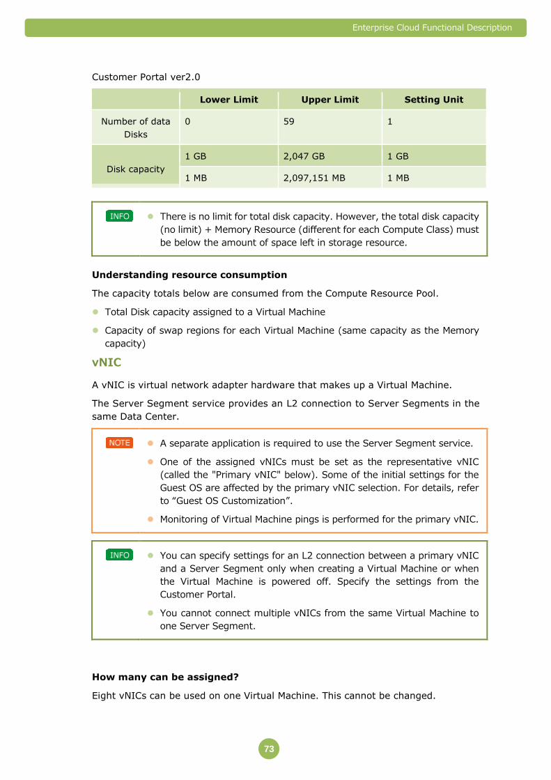
Enterprise Cloud Functional Description
73
Customer Portal ver2.0
Lower Limit Upper Limit Setting Unit
Number of data
Disks
0 59 1
Disk capacity
1 GB 2,047 GB 1 GB
1 MB 2,097,151 MB 1 MB
There is no limit for total disk capacity. However, the total disk capacity
(no limit) + Memory Resource (different for each Compute Class) must
be below the amount of space left in storage resource.
Understanding resource consumption
The capacity totals below are consumed from the Compute Resource Pool.
Total Disk capacity assigned to a Virtual Machine
Capacity of swap regions for each Virtual Machine (same capacity as the Memory
capacity)
vNIC
A vNIC is virtual network adapter hardware that makes up a Virtual Machine.
The Server Segment service provides an L2 connection to Server Segments in the
same Data Center.
A separate application is required to use the Server Segment service.
One of the assigned vNICs must be set as the representative vNIC
(called the "Primary vNIC" below). Some of the initial settings for the
Guest OS are affected by the primary vNIC selection. For details, refer
to “Guest OS Customization”.
Monitoring of Virtual Machine pings is performed for the primary vNIC.
You can specify settings for an L2 connection between a primary vNIC
and a Server Segment only when creating a Virtual Machine or when
the Virtual Machine is powered off. Specify the settings from the
Customer Portal.
You cannot connect multiple vNICs from the same Virtual Machine to
one Server Segment.
How many can be assigned?
Eight vNICs can be used on one Virtual Machine. This cannot be changed.
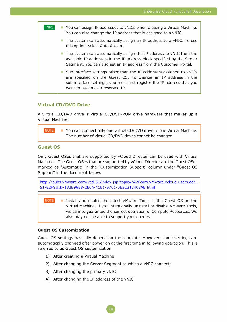
Enterprise Cloud Functional Description
74
You can assign IP addresses to vNICs when creating a Virtual Machine.
You can also change the IP address that is assigned to a vNIC.
The system can automatically assign an IP address to a vNIC. To use
this option, select Auto Assign.
The system can automatically assign the IP address to vNIC from the
available IP addresses in the IP address block specified by the Server
Segment. You can also set an IP address from the Customer Portal.
Sub-interface settings other than the IP addresses assigned to vNICs
are specified on the Guest OS. To change an IP address in the
sub-interface settings, you must first register the IP address that you
want to assign as a reserved IP.
Virtual CD/DVD Drive
A virtual CD/DVD drive is virtual CD/DVD-ROM drive hardware that makes up a
Virtual Machine.
You can connect only one virtual CD/DVD drive to one Virtual Machine.
The number of virtual CD/DVD drives cannot be changed.
Guest OS
Only Guest OSes that are supported by vCloud Director can be used with Virtual
Machines. The Guest OSes that are supported by vCloud Director are the Guest OSes
marked as "Automatic" in the "Customization Support" column under "Guest OS
Support" in the document below.
http://pubs.vmware.com/vcd-51/index.jsp?topic=%2Fcom.vmware.vcloud.users.doc_
51%2FGUID-132B96E8-2E0A-41E1-B701-0E3C213403AE.html
Install and enable the latest VMware Tools in the Guest OS on the
Virtual Machine. If you intentionally uninstall or disable VMware Tools,
we cannot guarantee the correct operation of Compute Resources. We
also may not be able to support your queries.
Guest OS Customization
Guest OS settings basically depend on the template. However, some settings are
automatically changed after power on at the first time in following operation. This is
referred to as Guest OS customization.
1) After creating a Virtual Machine
2) After changing the Server Segment to which a vNIC connects
3) After changing the primary vNIC
4) After changing the IP address of the vNIC
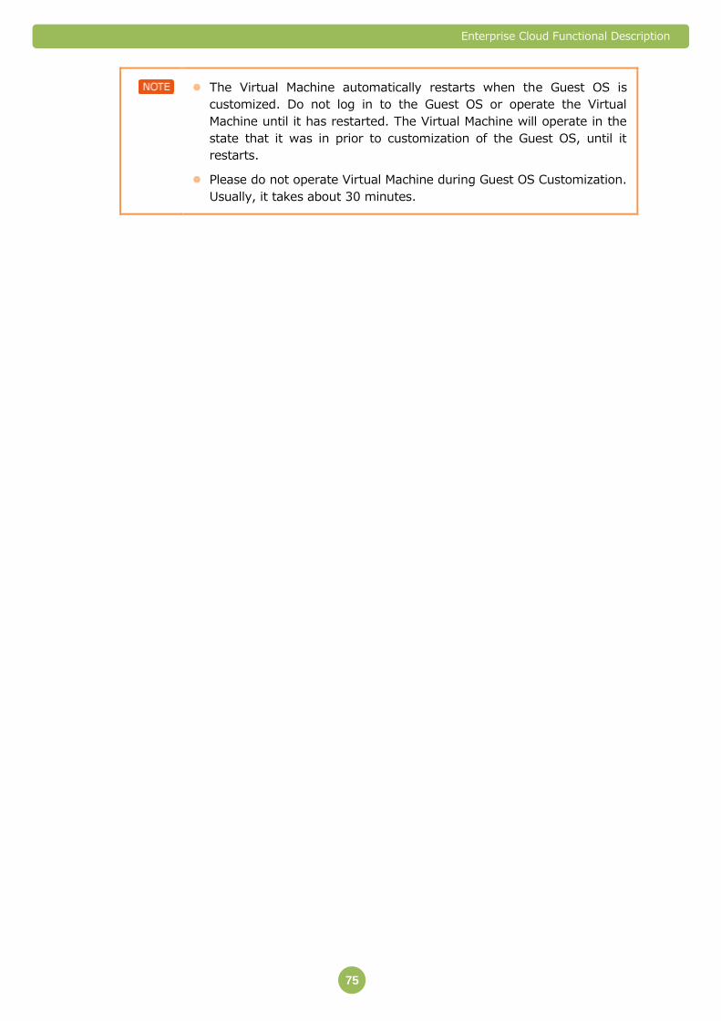
Enterprise Cloud Functional Description
75
The Virtual Machine automatically restarts when the Guest OS is
customized. Do not log in to the Guest OS or operate the Virtual
Machine until it has restarted. The Virtual Machine will operate in the
state that it was in prior to customization of the Guest OS, until it
restarts.
Please do not operate Virtual Machine during Guest OS Customization.
Usually, it takes about 30 minutes.

Enterprise Cloud Functional Description
76
Settings that are changed when customizing the Guest OS
The Guest OS settings that are changed when customizing the Guest OS are shown
below.
Items that are changed automatically when turning the power on for the first time
after creating a Virtual Machine.
Item Setting Remarks
IP Address A value specified by the user or
by NTT Communications
Applies to all vNICs.
Net mask The subnet mask of the Server
Segment to which the vNIC
connects
Applies to all vNICs.
Default gateway A value specified by the user or
by NTT Communications (※)
Primary DNS A value specified by the user or
by NTT Communications
Secondary DNS A value specified by the user or
by NTT Communications
DNS suffix A value specified by the user or
no value
S-ID - For Windows OS only, a
Sysprep is performed
and the S-ID is changed
automatically.
root/Admin password A value specified by NTT
Communications
Host/computer name A value specified by NTT
Communications
※ The settings that are specified by NTT Communications are the IP addresses for
the vFirewall/Integrated Network Appliance for the Server Segments to which
the primary vNIC connects. However, the IP address that is set for Server
Segments that do not connect to the vFirewall/Integrated Network Appliance is
"the "broadcast address" of the IP address block for the Server Segment - 1."
For example, if the IP address block is "192.168.0.0/24," the IP address that is
"the "broadcast address" of the IP address block for the Server Segment - 1" will
be "192.168.0.254."

Enterprise Cloud Functional Description
77
Settings that are changed automatically when starting for the first time after
changing the Server Segment to which the vNIC connects, the primary vNIC, or the
vNIC IP address
Item Setting Remarks
IP Address A value specified by the user or
by NTT Communications
Applies to the vNIC for
which the destination
Server Segment has
changed.
Net mask The subnet mask of the Server
Segment to which the vNIC
connects
Applies to the vNIC for
which the destination
Server Segment has
changed.
Default gateway A value specified by the user or
by NTT Communications (※)
Primary DNS A value specified by the user or
by NTT Communications
Secondary DNS A value specified by the user or
by NTT Communications
DNS suffix A value specified by the user or
no value
Host/computer name A value specified by NTT
Communications
※ The settings that are specified by NTT Communications are the IP addresses for
the vFirewall/Integrated Network Appliance for the Server Segments to which
the primary vNIC connects. However, the IP address that is set for Server
Segments that do not connect to the vFirewall/Integrated Network Appliance is
"the "broadcast address" of the IP address block for the Server Segment - 1."
For example, if the IP address block is "192.168.0.0/24," the IP address that is
"the "broadcast address" of the IP address block for the Server Segment - 1" will
be "192.168.0.254."
The S-ID and root/Admin password does not change.
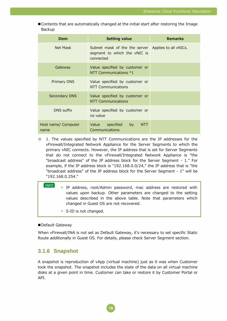
Enterprise Cloud Functional Description
78
Contents that are automatically changed at the initial start after restoring the Image
Backup
Item Setting value Remarks
Net Mask Subnet mask of the the server
segment to which the vNIC is
connected
Applies to all vNICs.
Gateway Value specified by customer or
NTT Communications *1
Primary DNS Value specified by customer or
NTT Communications
Secondary DNS Value specified by customer or
NTT Communications
DNS suffix Value specified by customer or
no value
Host name/ Computer
name
Value specified by NTT
Communications
※ 1. The values specified by NTT Communications are the IP addresses for the
vFirewall/Integrated Network Appliance for the Server Segments to which the
primary vNIC connects. However, the IP address that is set for Server Segments
that do not connect to the vFirewall/Integrated Network Appliance is "the
"broadcast address" of the IP address block for the Server Segment - 1." For
example, if the IP address block is "192.168.0.0/24," the IP address that is "the
"broadcast address" of the IP address block for the Server Segment - 1" will be
"192.168.0.254."
IP address, root/Admin password, mac address are restored with
values upon backup. Other parameters are changed to the setting
values described in the above table. Note that parameters which
changed in Guest OS are not recovered.
S-ID is not changed.
Default Gateway
When vFirewall/INA is not set as Default Gateway, it's necessary to set specific Static
Route additionally in Guest OS. For details, please check Server Segment section.
Snapshot 3.1.6
A snapshot is reproduction of vApp (virtual machine) just as it was when Customer
took the snapshot. The snapshot includes the state of the data on all virtual machine
disks at a given point in time. Customer can take or restore it by Customer Portal or
API.
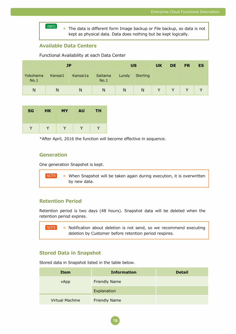
Enterprise Cloud Functional Description
79
The data is different form Image backup or File backup, so data is not
kept as physical data. Data does nothing but be kept logically.
Available Data Centers
Functional Availability at each Data Center
JP US UK DE FR ES
Yokohama
No.1
Kansai1 Kansai1a Saitama
No.1
Lundy Sterling
N N N N N N Y Y Y Y
SG HK MY AU TH
Y Y Y Y Y
*After April, 2016 the function will become effective in sequence.
Generation
One generation Snapshot is kept.
When Snapshot will be taken again during execution, it is overwritten
by new data.
Retention Period
Retention period is two days (48 hours). Snapshot data will be deleted when the
retention period expires.
Notification about deletion is not send, so we recommend executing
deletion by Customer before retention period respires.
Stored Data in Snapshot
Stored data in Snapshot listed in the table below.
Item Information Detail
vApp Friendly Name
Explanation
Virtual Machine Friendly Name
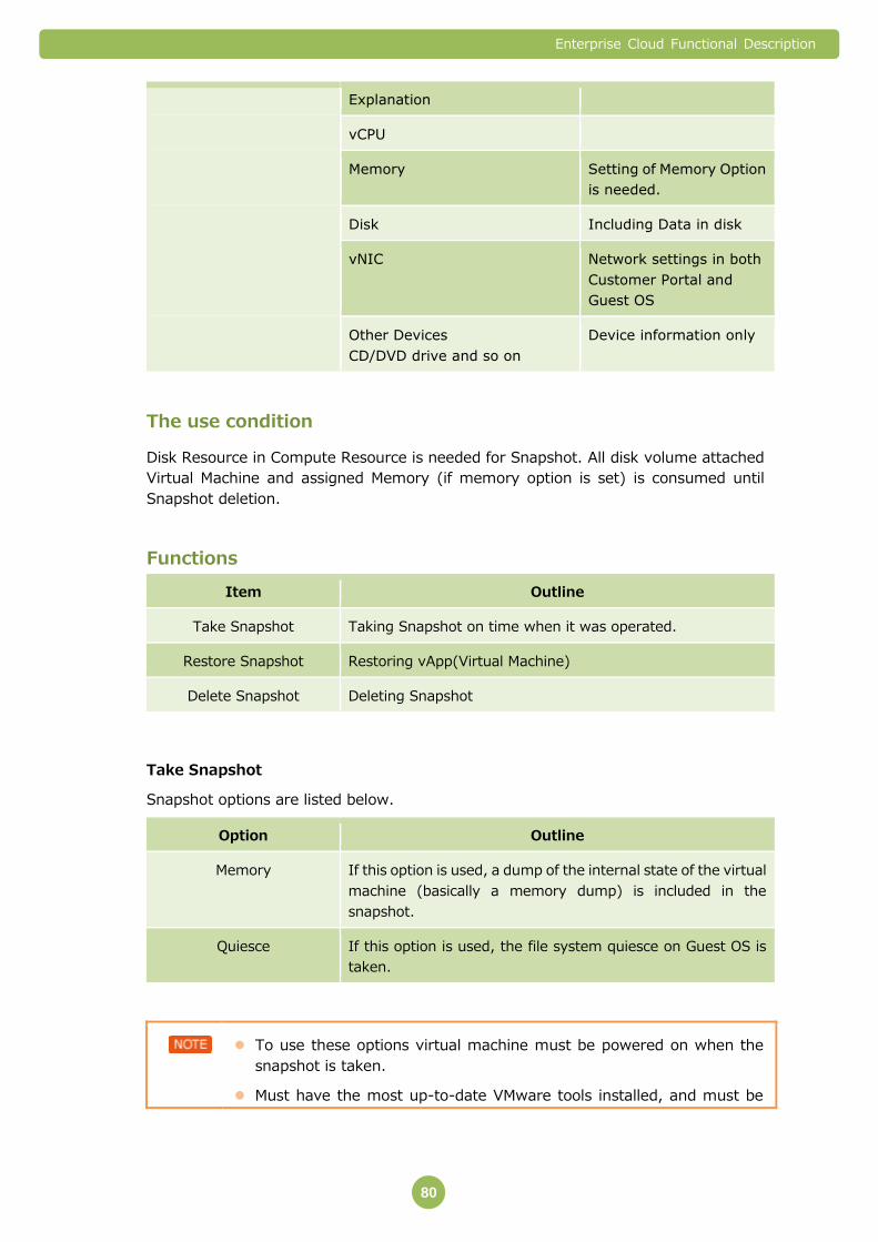
Enterprise Cloud Functional Description
80
Explanation
vCPU
Memory Setting of Memory Option
is needed.
Disk Including Data in disk
vNIC Network settings in both
Customer Portal and
Guest OS
Other Devices
CD/DVD drive and so on
Device information only
The use condition
Disk Resource in Compute Resource is needed for Snapshot. All disk volume attached
Virtual Machine and assigned Memory (if memory option is set) is consumed until
Snapshot deletion.
Functions
Item Outline
Take Snapshot Taking Snapshot on time when it was operated.
Restore Snapshot Restoring vApp(Virtual Machine)
Delete Snapshot Deleting Snapshot
Take Snapshot
Snapshot options are listed below.
Option Outline
Memory If this option is used, a dump of the internal state of the virtual
machine (basically a memory dump) is included in the
snapshot.
Quiesce If this option is used, the file system quiesce on Guest OS is
taken.
To use these options virtual machine must be powered on when the
snapshot is taken.
Must have the most up-to-date VMware tools installed, and must be
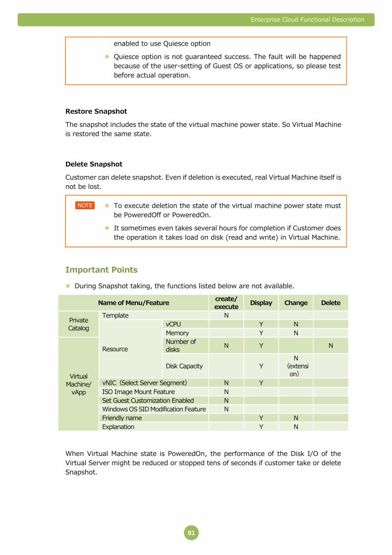
Enterprise Cloud Functional Description
81
enabled to use Quiesce option
Quiesce option is not guaranteed success. The fault will be happened
because of the user-setting of Guest OS or applications, so please test
before actual operation.
Restore Snapshot
The snapshot includes the state of the virtual machine power state. So Virtual Machine
is restored the same state.
Delete Snapshot
Customer can delete snapshot. Even if deletion is executed, real Virtual Machine itself is
not be lost.
To execute deletion the state of the virtual machine power state must
be PoweredOff or PoweredOn.
It sometimes even takes several hours for completion if Customer does
the operation it takes load on disk (read and write) in Virtual Machine.
Important Points
During Snapshot taking, the functions listed below are not available.
Name of Menu/Feature create/
execute Display Change Delete
Private
Catalog
Template N
Resource
vCPU Y N
Memory Y N
Virtual
Machine/
vApp
Number of
disks N Y N
Disk Capacity Y
N
(extensi
on)
vNIC(Select Server Segment) N Y
ISO Image Mount Feature N
Set Guest Customization Enabled N
Windows OS SID Modification Feature N
Friendly name Y N
Explanation Y N
When Virtual Machine state is PoweredOn, the performance of the Disk I/O of the
Virtual Server might be reduced or stopped tens of seconds if customer take or delete
Snapshot.

Enterprise Cloud Functional Description
82
It is recommended to take snapshot in the state of PoweredOff if the
affection cannot be estimated.
Please test this function and confirm the influence to the system before
actual operation.
Important Points 3.1.7
Resources Consumed by the Memory and Disk Overhead Regions
In Connection With Server Virtualization
Virtual machines have four types of power states. The consumption of resources in
the overhead regions for server virtualization depends on the power state. The
overheads therefore need to be taken into account when designing the system
(designing resources).
Each power state and the overhead regions required for each power state are shown
in the table below.
The items marked with a "Y" are items that consume resources in overhead regions.
For example, if the power state is Powered Off, resources from the overhead are not
consumed for the CPU and Memory. On the other hand, the overhead portion
consumes resources for the Disks.
Power State Meaning of Power State CPU Memory
(※1)
Disk
(※2)
Powered Off The power for the Virtual
Machine is off.
- - Y
Partially Powered Off The power for the Virtual
Machine is on but the Guest
OS is stopped.
- - Y
Powered On The power for the Virtual
Machine is on.
Y Y Y
Suspended The operation of the Virtual
Machine has been stopped
temporarily using the cloud
infrastructure.
The suspend state and sleep
state for the Guest OS is
different to hibernation.
- - Y
※6 The following overhead regions are required based on the number of vCPUs.
※7 The capacity of Disk resources consumed as the swap region is the same as the
used Memory capacity.
Memory resource overheads (reference values※)
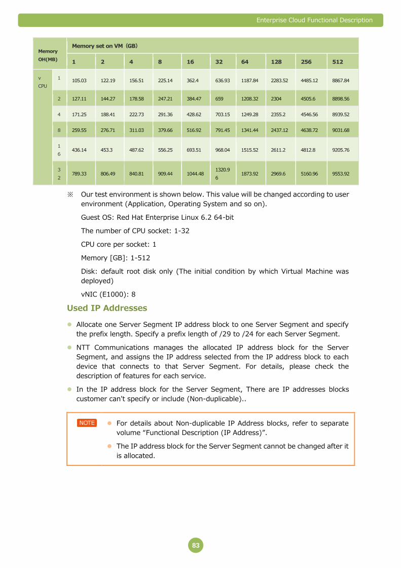
Enterprise Cloud Functional Description
83
Memory
OH(MB)
Memory set on VM(GB)
1 2 4 8 16 32 64 128 256 512
v
CPU
1 105.03 122.19 156.51 225.14 362.4 636.93 1187.84 2283.52 4485.12 8867.84
2 127.11 144.27 178.58 247.21 384.47 659 1208.32 2304 4505.6 8898.56
4 171.25 188.41 222.73 291.36 428.62 703.15 1249.28 2355.2 4546.56 8939.52
8 259.55 276.71 311.03 379.66 516.92 791.45 1341.44 2437.12 4638.72 9031.68
1
6 436.14 453.3 487.62 556.25 693.51 968.04 1515.52 2611.2 4812.8 9205.76
3
2 789.33 806.49 840.81 909.44 1044.48
1320.9
6 1873.92 2969.6 5160.96 9553.92
※ Our test environment is shown below. This value will be changed according to user
environment (Application, Operating System and so on).
Guest OS: Red Hat Enterprise Linux 6.2 64-bit
The number of CPU socket: 1-32
CPU core per socket: 1
Memory [GB]: 1-512
Disk: default root disk only (The initial condition by which Virtual Machine was
deployed)
vNIC (E1000): 8
Used IP Addresses
Allocate one Server Segment IP address block to one Server Segment and specify
the prefix length. Specify a prefix length of /29 to /24 for each Server Segment.
NTT Communications manages the allocated IP address block for the Server
Segment, and assigns the IP address selected from the IP address block to each
device that connects to that Server Segment. For details, please check the
description of features for each service.
In the IP address block for the Server Segment, There are IP addresses blocks
customer can't specify or include (Non-duplicable)..
For details about Non-duplicable IP Address blocks, refer to separate
volume “Functional Description (IP Address)”.
The IP address block for the Server Segment cannot be changed after it
is allocated.

Enterprise Cloud Functional Description
84
Restrictions on the Hardware Configuration for Compute Resource
If multiple Virtual Machines with the same role are created for one physical server
and that physical server fails, the applications on those Virtual Machines may stop at
the same time.
You cannot select a physical server that runs a specific Virtual Machine.
The network equipment and physical server interface provided by Compute
Resource has redundancy. If the interface fails, it automatically switches from the
regular interface to the standby interface. The Guest OS on the Virtual Machine and
the applications that are running on the Guest OS may be affected when switching
interfaces.
If the zone is the same, resources may be kept on the same physical server or
storage device, even if the service class (Premium or Standard) is different.
In maintenance there is a possibility that Virtual Machines may move to another
physical server using Live Migration function. Once it happens, Virtual Machine will
be momentarily stopped, however there is no effect in general use of Guest OS and
applications. And there are two possibilities that performance may fall and packet
loss according to the loading state of the virtual server and applications.
Enterprise Cloud Functional Description
85
Restrictions on the Settings for Compute Resource Application
Resources
The performance of each resource may vary by Data Center.
When changing Compute Resources, you need to create the Virtual Machines and
configure the resource settings for Virtual Machines yourself. NTT Communications
is not responsible for errors that occur as a result of these settings, such as
abnormal operation of your applications.
When changing Compute Resources, we may ask you to create a new
Compute Resource Pool to ensure that a stable service is provided, even
if the compute resource that you are changing has not reached the
resource upper limits.
Restrictions on Virtual Machine Disks
To use the Disk capacity expansion feature, you need to install and enable VMware
Tools (Version 8.6.0 or higher) in the Guest OS on the Virtual Machine.
The Disk capacity expansion feature cannot be used while a backup image is being
obtained.
You cannot reduce the Disk capacity.
Restrictions on Virtual Hardware
You cannot change MAC addresses that have been set on virtual hardware such as
vNIC.
You cannot use your own MAC addresses that are not administered by NTT
Communications.
If we become aware that you have changed a MAC address or are using your own
MAC address, we may stop that Virtual Machine without advance notice.
Enterprise Cloud Functional Description
86
Restrictions on the Guest OS and Applications
When installing a Guest OS on a Virtual Machine, you need to verify the system
requirements for the Guest OS (number of vCPUs, Memory capacity, Disk capacity,
and so on), licenses, and terms of support with your Guest OS vendor yourself.
When installing applications on a Guest OS, you need to verify the system
requirements for the application (number of vCPUs, the CPU processing capacity of
the vCPU, Memory capacity, number and capacity of Disks, number of vNICs, and so
on), licenses, and terms of support with your application vendor yourself.
When you install a Guest OS or application, NTT Communications is not responsible
for checking or reporting whether operations can be guaranteed in your system
configuration or whether there are any licensing issues.
The Guest OS will recognize a vNIC as a NIC, even if it is not connected to a Server
Segment. When changing the Guest OS network settings, do not disable a vNIC that
has been recognized, even if you are not using that vNIC. If you do disable it, errors
may occur in services such as Private Catalog and Image Backup.
Other
Compute Resource uses software that NTT Communications has licensed from
VMWare, Inc.
The VMware features provided in Compute Resource have been selected based on
Compute Resource specifications. Not all VMware features are included.
The following virtualization software is used in Compute Resource.
- VMware vSphere
- VMware vCloud Director
- Equivalent successor products
Suspended new sales of the Compute Resorce
New sale of Premium Compute and Standard Comute is suspended.
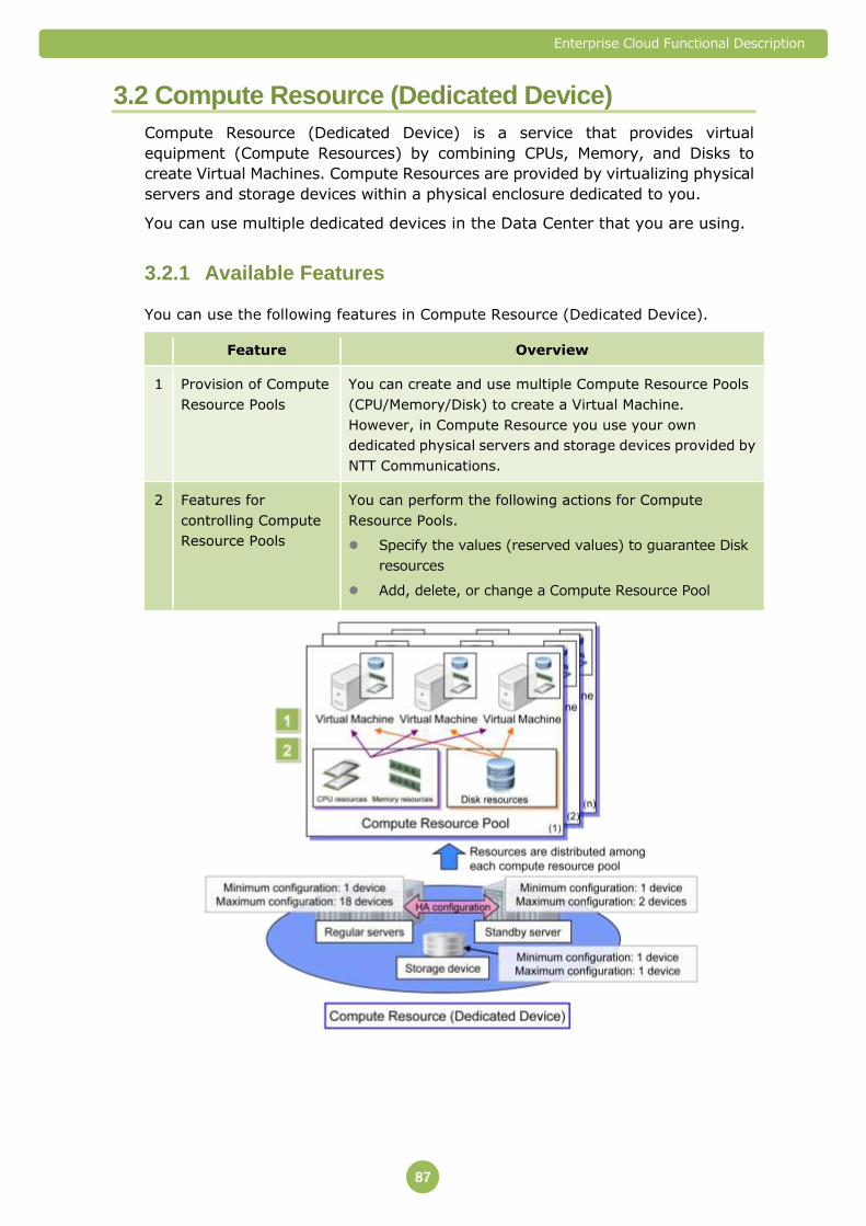
Enterprise Cloud Functional Description
87
3.2 Compute Resource (Dedicated Device)
Compute Resource (Dedicated Device) is a service that provides virtual
equipment (Compute Resources) by combining CPUs, Memory, and Disks to
create Virtual Machines. Compute Resources are provided by virtualizing physical
servers and storage devices within a physical enclosure dedicated to you.
You can use multiple dedicated devices in the Data Center that you are using.
Available Features 3.2.1
You can use the following features in Compute Resource (Dedicated Device).
Feature Overview
1 Provision of Compute
Resource Pools
You can create and use multiple Compute Resource Pools
(CPU/Memory/Disk) to create a Virtual Machine.
However, in Compute Resource you use your own
dedicated physical servers and storage devices provided by
NTT Communications.
2 Features for
controlling Compute
Resource Pools
You can perform the following actions for Compute
Resource Pools.
Specify the values (reserved values) to guarantee Disk
resources
Add, delete, or change a Compute Resource Pool

Enterprise Cloud Functional Description
88
Compute Resource (Dedicated Device) is a service that provides the
same features as Compute Resource, the service in which physical
equipment is shared with other users. This section explains the
differences between the two services. For information regarding
Compute Resource, refer to "3
Compute Resource" (⇒P.56).
You can select storage devices from a storage class (Premium or
Premium+) that offers the appropriate performance level for your
intended use.
Provision of Compute Resource Pools 3.2.2
In Compute Resource (Dedicated Device), you can use Compute Resources
(CPU/Memory/Disk) that are comprised of your own dedicated physical servers and
storage devices provided by NTT Communications. In addition, you can divide your
Compute Resources into multiple Compute Resource Pools.
To add, delete, or change a Compute Resource Pool, please submit the application
specified separately.
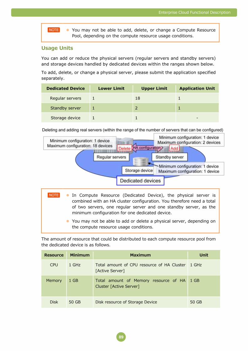
Enterprise Cloud Functional Description
89
You may not be able to add, delete, or change a Compute Resource
Pool, depending on the compute resource usage conditions.
Usage Units
You can add or reduce the physical servers (regular servers and standby servers)
and storage devices handled by dedicated devices within the ranges shown below.
To add, delete, or change a physical server, please submit the application specified
separately.
Dedicated Device Lower Limit Upper Limit Application Unit
Regular servers 1 18 1
Standby server 1 2 1
Storage device 1 1 -
In Compute Resource (Dedicated Device), the physical server is
combined with an HA cluster configuration. You therefore need a total
of two servers, one regular server and one standby server, as the
minimum configuration for one dedicated device.
You may not be able to add or delete a physical server, depending on
the compute resource usage conditions.
The amount of resource that could be distributed to each compute resource pool from
the dedicated device is as follows.
Resource Minimum Maximum Unit
CPU 1 GHz Total amount of CPU resource of HA Cluster
[Active Server]
1 GHz
Memory 1 GB Total amount of Memory resource of HA
Cluster [Active Server]
1 GB
Disk 50 GB Disk resource of Storage Device 50 GB

Enterprise Cloud Functional Description
90
There is no limit for total disk capacity. However, the total disk capacity
(no limit) + Memory Resource (different for each Compute Class) must
be below the amount of space left in storage resource.
Classes The Compute Resource Pool is comprised of two classes: a Compute Class
(CPU and Memory) provided by a physical server, and a storage class (Disks)
provided by a storage device. You can choose from three different service class
(Small/Medium/Large) that has different resource capacity. Storage classes are
separated into two types of service classes (Premium and Premium+) with different
levels of Disk performance. You can select the class that is appropriate for your
intended use.
Classes Resource Service Class Details
Compute Class
(Physical server)
CPU
Memory
Small The Physical Server of Small is the
smallest. The physical server of Small
provides smaller CPU Resource and
Memory Resource than Medium.
Medium The Physical Server of Medium is
larger than that of Small and smaller
than that of Large. The physical
server of Medium provides larger CPU
Resource and Memory Resource than
Small.
Large The Physical Server of Large is the
largest. The Physical Server of Large
provides the largest CPU Resource
and Memory. The CPU performance
is higher than that of Medium.
Storage Class
(Storage device)
Disk Premium Provides a Disk resource with
high-speed Disk performance
(equivalent to iSCSI).
Premium+ Provides a Disk resource with faster
Disk performance than Premium
(equivalent to FC).

Enterprise Cloud Functional Description
91
Physical server performance
The physical configurations of one physical server that are provided are shown
below.
Generation Class
Number of
physical
CPU
sockets
Total of
physical
CPU cores
CPU※
(GHz)
Memory※
(GB)
CPU
processing
capacity
Generation1
Small 2 16 32 128 Intel Xeon
2.0GHz
Medium 4 32 70.4 192 Intel Xeon
2.0GHz
Large 4 32 86.4 768 Intel Xeon
2.0GHz
Generation2
Small 2 16 41.6 128 Intel Xeon
2.6GHz
Medium 4 32 83.2 192 Intel Xeon
2.6GHz
Large 4 32 83.2 768 Intel Xeon
2.6GHz
Generation3
Small 2 16 38.4 128 Intel Xeon
2.4GHz
Medium 4 40 80 192 Intel Xeon
2.0GHz
Large 4 40 80 768 Intel Xeon
2.0GHz
※ About 10%-15% overhead is required for virtualization. So Customer can use
the following amount resource approximately. As of February, 2015.
Available Resource by 1 physical server (as of December 2015)
Generation Class CPU
Resource(GHz)
Memory
Resource(GB)
Generation1 Small 27 115
Medium 65 182
Large 80 730
Generation2 Small 35 115
Medium 75 176
Large 75 729
Generation3 Small 32 115
Medium 72 176
Large 72 729
The processing capacity of a CPU that provides 1 GHz of CPU resource is
equivalent to the processing capacity when the physical processor
above operates at 1 GHz.
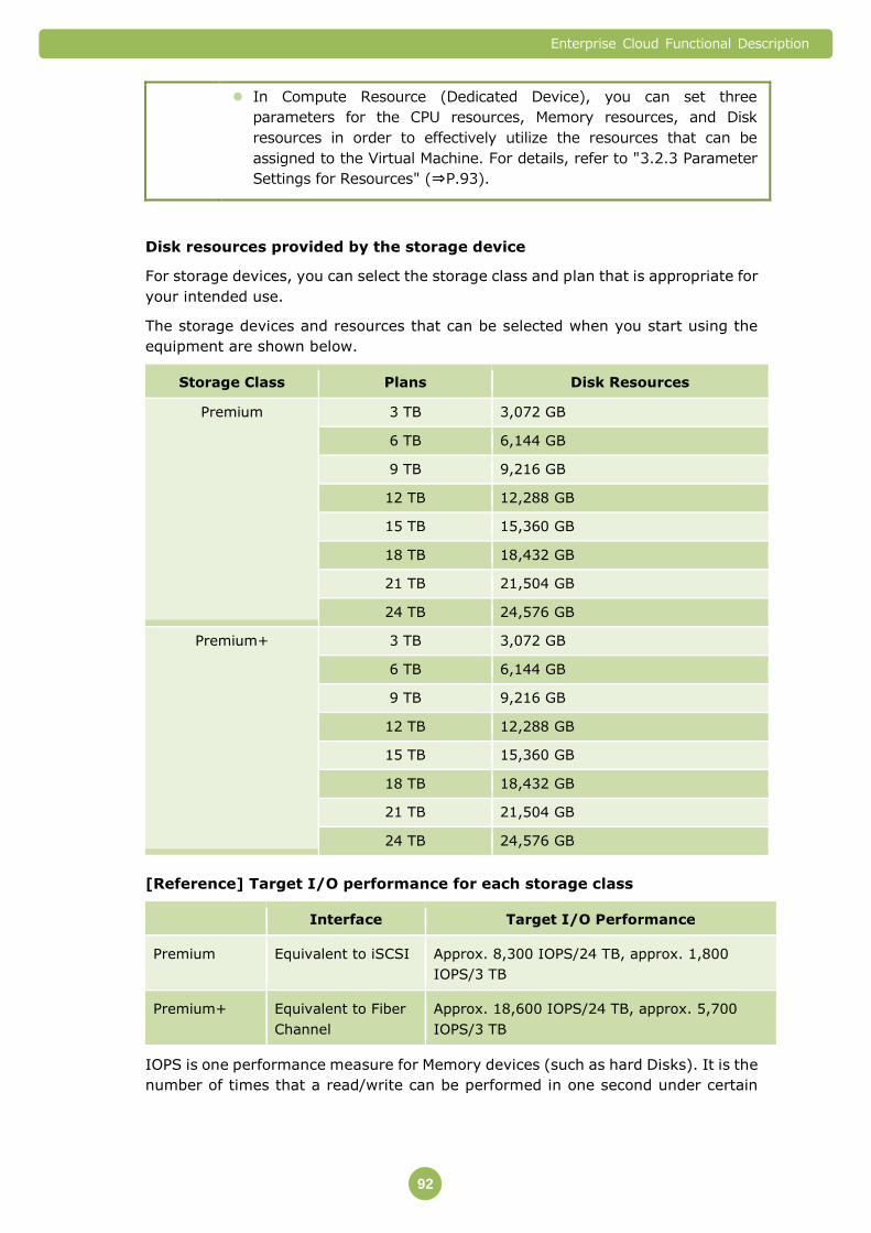
Enterprise Cloud Functional Description
92
In Compute Resource (Dedicated Device), you can set three
parameters for the CPU resources, Memory resources, and Disk
resources in order to effectively utilize the resources that can be
assigned to the Virtual Machine. For details, refer to "3.2.3 Parameter
Settings for Resources" (⇒P.93).
Disk resources provided by the storage device
For storage devices, you can select the storage class and plan that is appropriate for
your intended use.
The storage devices and resources that can be selected when you start using the
equipment are shown below.
Storage Class Plans Disk Resources
Premium 3 TB 3,072 GB
6 TB 6,144 GB
9 TB 9,216 GB
12 TB 12,288 GB
15 TB 15,360 GB
18 TB 18,432 GB
21 TB 21,504 GB
24 TB 24,576 GB
Premium+ 3 TB 3,072 GB
6 TB 6,144 GB
9 TB 9,216 GB
12 TB 12,288 GB
15 TB 15,360 GB
18 TB 18,432 GB
21 TB 21,504 GB
24 TB 24,576 GB
[Reference] Target I/O performance for each storage class
Interface Target I/O Performance
Premium Equivalent to iSCSI Approx. 8,300 IOPS/24 TB, approx. 1,800
IOPS/3 TB
Premium+ Equivalent to Fiber
Channel
Approx. 18,600 IOPS/24 TB, approx. 5,700
IOPS/3 TB
IOPS is one performance measure for Memory devices (such as hard Disks). It is the
number of times that a read/write can be performed in one second under certain

Enterprise Cloud Functional Description
93
conditions. The IOPS values above are the performance values measured under the
following conditions.
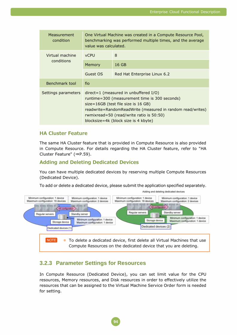
Enterprise Cloud Functional Description
94
Measurement
condition
One Virtual Machine was created in a Compute Resource Pool,
benchmarking was performed multiple times, and the average
value was calculated.
Virtual machine
conditions
vCPU 8
Memory 16 GB
Guest OS Red Hat Enterprise Linux 6.2
Benchmark tool fio
Settings parameters direct=1 (measured in unbuffered I/O)
runtime=300 (measurement time is 300 seconds)
size=16GB (test file size is 16 GB)
readwrite=RandomReadWrite (measured in random read/writes)
rwmixread=50 (read/write ratio is 50:50)
blocksize=4k (block size is 4 kbyte)
HA Cluster Feature
The same HA Cluster feature that is provided in Compute Resource is also provided
in Compute Resource. For details regarding the HA Cluster feature, refer to "HA
Cluster Feature" (⇒P.59).
Adding and Deleting Dedicated Devices
You can have multiple dedicated devices by reserving multiple Compute Resources
(Dedicated Device).
To add or delete a dedicated device, please submit the application specified separately.
To delete a dedicated device, first delete all Virtual Machines that use
Compute Resources on the dedicated device that you are deleting.
Parameter Settings for Resources 3.2.3
In Compute Resource (Dedicated Device), you can set limit value for the CPU
resources, Memory resources, and Disk resources in order to effectively utilize the
resources that can be assigned to the Virtual Machine Service Order form is needed
for setting.

Enterprise Cloud Functional Description
95
The items marked with a "Y" are items that can be set. For example, a limit value can
be set for CPU resources and Memory resources.
Item Description CPU Memory Disk
Limit value Sets the upper limit of the
resources that a Compute
Resource Pool can use.
Y Y -
Reservation
rate
Sets the percentage value
of the reservation value
for the limit value.
Specified by
NTT
Communications
Specified by
NTT
Communications
-
Reservation
value
Sets the resource value
that the Compute
Resource Pool can
definitely use.
Specified by
NTT
Communications
Specified by
NTT
Communications
Y
CPU Resources
You can add or reduce CPU resources within the ranges shown below.
Lower Limit Upper Limit Setting Unit
Limit value 1 GHz The resource value
provided by the HA
cluster
1 GHz
Memory Resources
You can add or reduce Memory resources within the ranges shown below.
Lower Limit Upper Limit Setting Unit
Limit value 1 GB The resource value
provided by the HA
cluster
1 GB
Disk Resources
You can add or reduce Disk resources within the ranges shown below.
Lower Limit Upper Limit Setting Unit
Reservation value 50 GB Disk resources
provided by the
storage device
1 GB
The total of the Disk resource reserved rates for all Compute Resources
that belong to the same storage device cannot exceed the Disk
resources provided by that storage.
Enterprise Cloud Functional Description
96
The Disk resources listed in the Customer Portal may vary slightly from
the values in the table.
Disk performance varies according to the storage class. For details,
refer to "Class" (⇒P.88).
Assigning Resources to a Virtual Machine 3.2.4
Create a Virtual Machine by assigning resources in a Compute Resource Pool
(CPUs/Memory/Disk) to the Virtual Machine.
vCPU
The quantities of vCPUs that can be assigned to one Virtual Machine are shown
below.
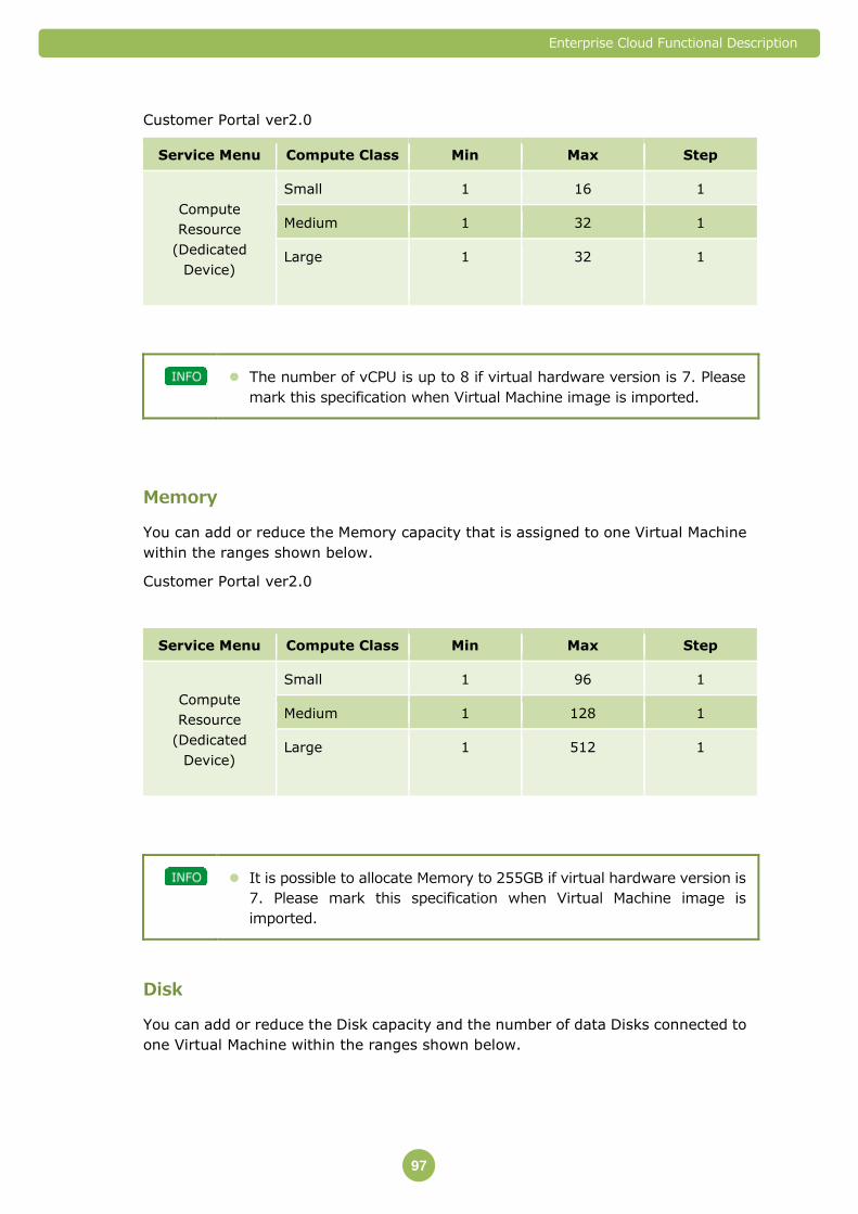
Enterprise Cloud Functional Description
97
Customer Portal ver2.0
Service Menu Compute Class Min Max Step
Compute
Resource
(Dedicated
Device)
Small 1 16 1
Medium 1 32 1
Large 1 32 1
The number of vCPU is up to 8 if virtual hardware version is 7. Please
mark this specification when Virtual Machine image is imported.
Memory
You can add or reduce the Memory capacity that is assigned to one Virtual Machine
within the ranges shown below.
Customer Portal ver2.0
Service Menu Compute Class Min Max Step
Compute
Resource
(Dedicated
Device)
Small 1 96 1
Medium 1 128 1
Large 1 512 1
It is possible to allocate Memory to 255GB if virtual hardware version is
7. Please mark this specification when Virtual Machine image is
imported.
Disk
You can add or reduce the Disk capacity and the number of data Disks connected to
one Virtual Machine within the ranges shown below.
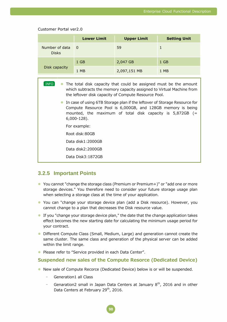
Enterprise Cloud Functional Description
98
Customer Portal ver2.0
Lower Limit Upper Limit Setting Unit
Number of data
Disks
0 59 1
Disk capacity
1 GB 2,047 GB 1 GB
1 MB 2,097,151 MB 1 MB
The total disk capacity that could be assigned must be the amount
which subtracts the memory capacity assigned to Virtual Machine from
the leftover disk capacity of Compute Resource Pool.
In case of using 6TB Storage plan if the leftover of Storage Resource for
Compute Resource Pool is 6,000GB, and 128GB memory is being
mounted, the maximum of total disk capacity is 5,872GB (=
6,000-128).
For example:
Root disk:80GB
Data disk1:2000GB
Data disk2:2000GB
Data Disk3:1872GB
Important Points 3.2.5
You cannot "change the storage class (Premium or Premium+)" or "add one or more
storage devices." You therefore need to consider your future storage usage plan
when selecting a storage class at the time of your application.
You can "change your storage device plan (add a Disk resource). However, you
cannot change to a plan that decreases the Disk resource value.
If you "change your storage device plan," the date that the change application takes
effect becomes the new starting date for calculating the minimum usage period for
your contract.
Different Compute Class (Small, Medium, Large) and generation cannot create the
same cluster. The same class and generation of the physical server can be added
within the limit range.
Please refer to “Service provided in each Data Center”.
Suspended new sales of the Compute Resorce (Dedicated Device)
New sale of Compute Recorce (Dedicated Device) below is or will be suspended.
- Generation1 all Class
- Genaration2 small in Japan Data Centers at January 8th, 2016 and in other
Data Centers at February 29th, 2016.

Enterprise Cloud Functional Description
99
3.3 Private Catalog
Private Catalog is a service that provides Disks for storing templates of Virtual
Machines that you have created. You can create new Virtual Machines from the
templates saved in Private Catalog.
Available Features 3.3.1
You can use the following features in Private Catalog.
Feature Overview
1
Provision of a Disk for
saving template catalogs
A feature that provides a Disk region for saving Virtual
Machine templates and adds or reduces the capacity.
You can create new Virtual Machines from the templates
saved in this Disk region.
2 Create Template feature A feature that converts a created Virtual Machine into a
template. You can also delete created templates.
3 Import Template feature A feature for importing Virtual Machine images created
on a local server to Private Catalog.
4 Export Template feature A feature for exporting templates stored in Private
Catalog to a local server.
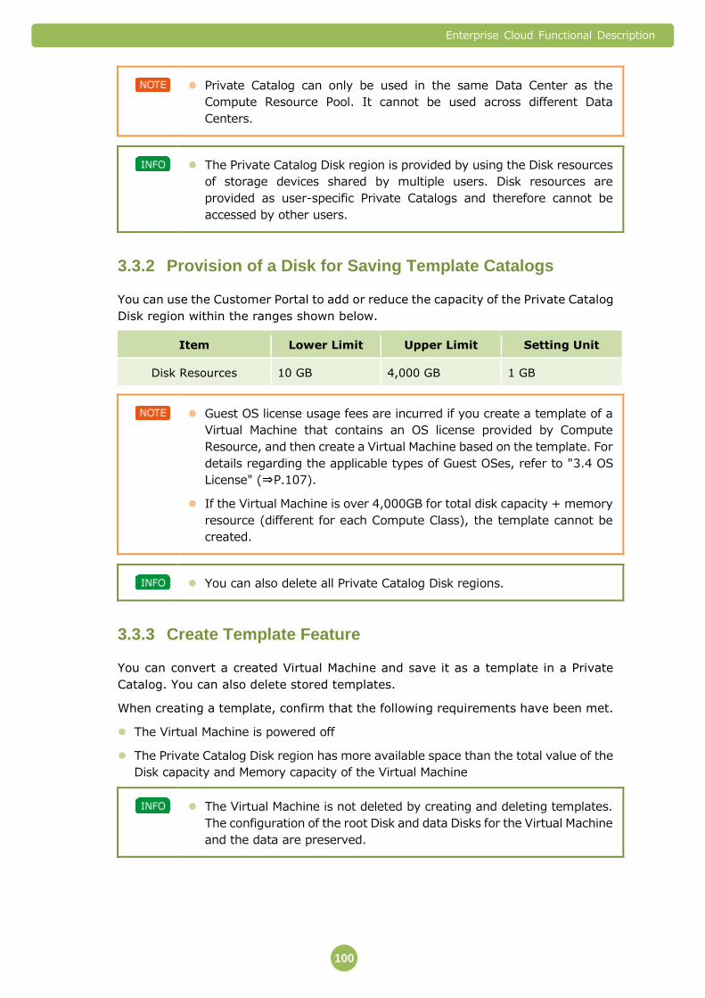
Enterprise Cloud Functional Description
100
Private Catalog can only be used in the same Data Center as the
Compute Resource Pool. It cannot be used across different Data
Centers.
The Private Catalog Disk region is provided by using the Disk resources
of storage devices shared by multiple users. Disk resources are
provided as user-specific Private Catalogs and therefore cannot be
accessed by other users.
Provision of a Disk for Saving Template Catalogs 3.3.2
You can use the Customer Portal to add or reduce the capacity of the Private Catalog
Disk region within the ranges shown below.
Item Lower Limit Upper Limit Setting Unit
Disk Resources 10 GB 4,000 GB 1 GB
Guest OS license usage fees are incurred if you create a template of a
Virtual Machine that contains an OS license provided by Compute
Resource, and then create a Virtual Machine based on the template. For
details regarding the applicable types of Guest OSes, refer to "3.4 OS
License" (⇒P.107).
If the Virtual Machine is over 4,000GB for total disk capacity + memory
resource (different for each Compute Class), the template cannot be
created.
You can also delete all Private Catalog Disk regions.
Create Template Feature 3.3.3
You can convert a created Virtual Machine and save it as a template in a Private
Catalog. You can also delete stored templates.
When creating a template, confirm that the following requirements have been met.
The Virtual Machine is powered off
The Private Catalog Disk region has more available space than the total value of the
Disk capacity and Memory capacity of the Virtual Machine
The Virtual Machine is not deleted by creating and deleting templates.
The configuration of the root Disk and data Disks for the Virtual Machine
and the data are preserved.
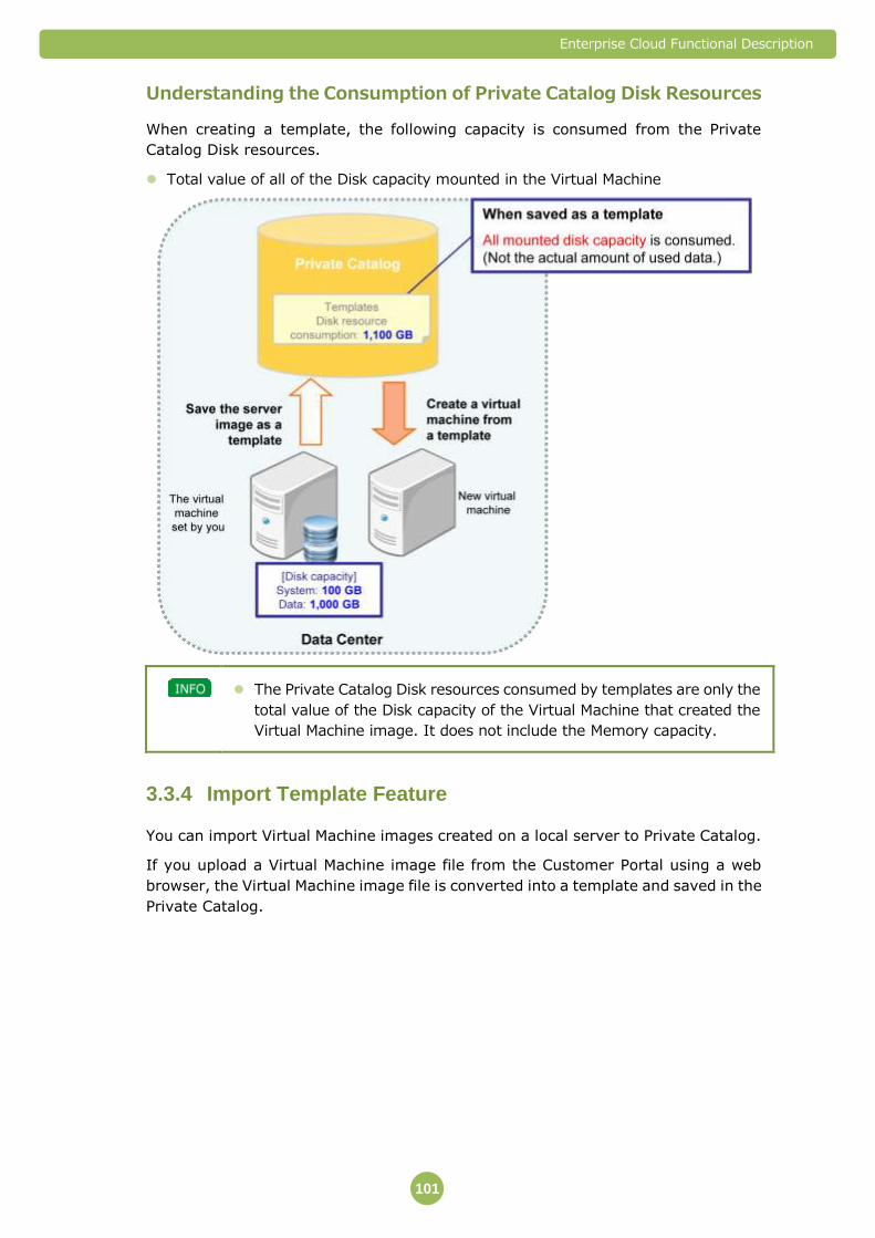
Enterprise Cloud Functional Description
101
Understanding the Consumption of Private Catalog Disk Resources
When creating a template, the following capacity is consumed from the Private
Catalog Disk resources.
Total value of all of the Disk capacity mounted in the Virtual Machine
The Private Catalog Disk resources consumed by templates are only the
total value of the Disk capacity of the Virtual Machine that created the
Virtual Machine image. It does not include the Memory capacity.
Import Template Feature 3.3.4
You can import Virtual Machine images created on a local server to Private Catalog.
If you upload a Virtual Machine image file from the Customer Portal using a web
browser, the Virtual Machine image file is converted into a template and saved in the
Private Catalog.

Enterprise Cloud Functional Description
102
To import a Virtual Machine image, you will require more available
space in the Private Catalog Disk region than the total of the Disk
capacity and Memory capacity of the Virtual Machine image that is
being imported (not the file size of the actual OVA file).
You are responsible for appropriately managing licenses for software
such as Guest OSes and applications included in the imported Virtual
Machine image. For example, please check with the vendor of your
Guest OS or application to confirm that the license can be used in
Compute Resource, prior to use.
For the Guest OS to import and use a Virtual Machine image of Windows
Server, you will need to switch the SPLA OS license.
Understanding the Consumption of Private Catalog Disk Resources
When importing a template, the following capacity is consumed from the Private
Catalog Disk resources.
Total value of all of the Disk capacity mounted in the Virtual Machine
The Private Catalog Disk resources consumed by templates are only the
total value of the Disk capacity of the Virtual Machine that created the
Virtual Machine image. It does not include the Memory capacity.
Enterprise Cloud Functional Description
103
VM Image Import Function
In order to import a VM to Enterprise cloud environment, the VM must be created in
either one of the (2) environments listed below.
1. VMware vSphere 4.x and above
2. VMware ESXi 4.x and above
In addition to the above, customers are requested to use vCloud Director (VCD) 1.5
and above.
Company takes no responsibility that the imported VM (including the Operating System
and application within the VM) will function as intended by the customer.
Requirements to create a VM image
Customers are requested to read and understand the following document from
VMware vSphere Document Center in order to export a VM image as an OVF template.
(External Link)
http://pubs.vmware.com/vsphere-50/topic/com.vmware.ICbase/PDF/vsphere-esxi-v
center-server-50-virtual-machine-admin-guide.pdf
When creating a VM image (exporting to OVF template), the following conditions must
be met:
- Customers are requested to use vCD to set “Enable Guest Customization” to
“On”. Customers must prepare the VCD environment.
- The VM image must be shutdown properly. VMs that were improperly
shutdown prior to creating a VM image may not function when imported to the
Enterprise Cloud environment.
- The VM within the VM image is limited to one VM. VM images with multiple
VMs (such as vApps) may not be imported to Enterprise Cloud environment.
- All virtual disk files within the VM image must be a single virtual disk file (VMDK
file). A VMDK file that is split into multiple files cannot be supported.
Requirements of VM image
The VM image must be a single file in OVA format v1.0.0 or 1.1.0.
The size of the OVA file must be 250GB or less.
All characters (text) used within the OVA template, including the OVA file name and
parameters within the VM image may not use the following characters.
‘ ’ (space)
multi-byte characters
Characters that may not be used in Microsoft Windows
Other characters that are not listed as UTF-8
Requirements of Virtual Hardware

Enterprise Cloud Functional Description
104
Windows Linux
Virtual Hardware version
7,8,9
OS type of Virtual Hardware
OS type that is appropriate for the installed Guest OS
Virtual Devices Required CPU, Memory, Video Card, VMCI Device, SCSI Controller, CD/DVD drive (1st drive), Floppy Drive (1st drive), Hard Disk (1st drive)
Virtual Devices Not Supported
Parallel Port, SCSI Device, Serial Port, USB Controller, USB Device, PCI Device, CD/DVD drive (2nd device or more), Floppy Drive (2nd device or more)
SCSI Bus Sharing None
SCSI Controller LSI Logic SAS recommended LSI Logic Parallel recommend
vCPU 1, 2, 4, 6 or 8
CPU Cores 1 Core per Socket
CPU Resource Allocation Limit
Must be “Unlimited”
Memory More than 1GB, Less than 32 GB
Virtual Disk Type Thin Provisioning recommended, may be thick provisioned
Virtual Disk numbers Max. 7 virtual disks (including root disk), cannot be in “Independent Mode”
Virtual Device Node of root disk *1
SCSI(0:0)
Virtual Disk size *2 Less than or equal to 2000GB for all virtual disks
vNIC *3 Recommended to delete all vNICs beforehand (will be deleted when importing)
VMCI Must be disabled
CD/DVD Device*4 Host Device Mount or Client Device Mount
CD/DVD Drive Must be either in “Host Device Mount” or “Client Device Mount”
setting
※1 Root disk cannot be changed after importing to Enterprise Cloud environment
※2 When uploading a VM image to Enterprise Cloud environment, it is required
to have sufficient space available in the private catalog. The uploaded VM size
should be calculated by the virtual disk size, not the thin provisioned file size.
For example, if a customer has created a VM image (OVA) with 5 virtual disks
each with 500 GB in size, the VM image may be small as 100 GB if using thin
provisioned virtual disks. In this case, the total of the virtual disk size would be

Enterprise Cloud Functional Description
105
2,500GB (500GB x 5) and would fail when importing the VM to Enterprise
Cloud.
※3 Existing vNICs should be deleted and new vNICs should be created in such a
way that Company can support during the post process of VM image import.
※4 VM image which includes mounted ISO image cannot be imported. Please
create VM image after ISO image is unmounted.
Requirements of Guest OS
A list of Guest OS’s that may be imported can be found at the following VMware
document (external link):
http://pubs.vmware.com/vcd-51/index.jsp?topic=%2Fcom.vmware.vcloud.users
.doc_51%2FGUID-132B96E8-2E0A-41E1-B701-0E3C213403AE.html
Please refer to Chapter 9 “Working with Virtual Machines”, Section “Guest
Operating System” and refer to the table in “Guest Operating System Support”.
Guest OS installed in the VM image must have Guest Customization as
“Automatic”.
Export Template Feature 3.3.5
You can convert a Private Catalog template to a Virtual Machine image and export it
from the Customer Portal to your own environment using a Web browser.
If NTT Communications owns the licenses for software included in the
exported Virtual Machine image, such as the Guest OS and applications,
the continued use of those licenses on your local computer is a license
violation and is therefore not permitted. In this situation, you are
responsible for appropriately managing licenses by replacing the
licenses for such software with licenses that you own.
Download sessions established while logged in to the Customer Portal
can be continued after logging out of the Customer Portal. However, the
download session may be terminated after downloading continuously
for more than 48 hours.
A template is not deleted even if you export it.

Enterprise Cloud Functional Description
106
Important Points 3.3.6
Important Points regarding the Windows Server Guest OS
When creating a Virtual Machine from a template that uses Windows Server as the
Guest OS, Sysprep will automatically run the first time that you start the Virtual
Machine. Sysprep is a tool that configures Windows OS system settings in advance.
Microsoft product specifications and license terms allow you to run
Sysprep up to the limit listed below. If you exceed this limit, you may
not be able to use the Virtual Machine.
Windows Server 2012 R2: 1000 times
Windows Server 2012: 1000 times
Windows Server 2008 R2: 3 times
※Once the virtual machine is created from the template, you will be
using up the limited times for Sysprep running.
Important Points regarding Guest OS Settings
In case of using Create Template Feature
When changing the Guest OS network settings, do not disable Network Adaptor
(NICS) that has been recognized in the Customer Portal, even if you are not using
that Adaptor. Creating a Virtual Machine from a template in which Adaptor is
disabled in the Guest OS may result in errors.
In case of using Import Template Feature
Windows Linux
Configuration of Firewall
within Guest OS *1
Must permit ICMP
(Company monitors VM using ICMP ping)
Perl N/A Must use Perl pre-installed in
the Guest OS
Network Adaptor (NICs) Must not disable Network Adaptor (NICs) from Guest OS
VMware Tools Must have the most up-to-date VMware tools installed, and must
be automatically enabled when a VM is turned on
※1 Customer has the responsibility to secure the VM. Customer may do so by
configuring the vFirewall that Enterprise Cloud provides and/or by using the
firewall within the Guest OS or by using other methods.
All software that requires certain hardware (such as hardware monitoring agents) must
be uninstalled or disabled before creating a VM image.

Enterprise Cloud Functional Description
107
It is the sole responsibility of the customer to comply with all license agreements of the
OS, applications, etc. when creating and importing a VM image to Enterprise Cloud
environment.
When importing a VM with a specific version of Windows Server, there is a possibility to
switch the license from customer owned to a license that the company provides in
Enterprise Cloud. Please contact your local sales representative for details.
Important Points regarding Serves Segment deletion
Server Segment cannot be deleted as long as the template exists on Private Catalog,
when Virtual Machine which vNIC connecting the Server Segment is converted. When
there is a schedule which deletes Server Segment, please convert Virtual Machine after
removing vNIC from the Server Segment in advance.
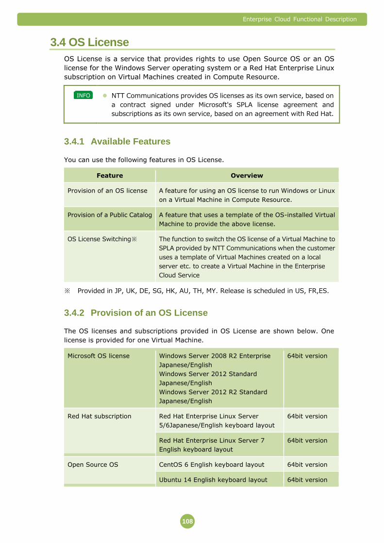
Enterprise Cloud Functional Description
108
3.4 OS License
OS License is a service that provides rights to use Open Source OS or an OS
license for the Windows Server operating system or a Red Hat Enterprise Linux
subscription on Virtual Machines created in Compute Resource.
NTT Communications provides OS licenses as its own service, based on
a contract signed under Microsoft's SPLA license agreement and
subscriptions as its own service, based on an agreement with Red Hat.
Available Features 3.4.1
You can use the following features in OS License.
Feature Overview
Provision of an OS license A feature for using an OS license to run Windows or Linux
on a Virtual Machine in Compute Resource.
Provision of a Public Catalog A feature that uses a template of the OS-installed Virtual
Machine to provide the above license.
OS License Switching※ The function to switch the OS license of a Virtual Machine to
SPLA provided by NTT Communications when the customer
uses a template of Virtual Machines created on a local
server etc. to create a Virtual Machine in the Enterprise
Cloud Service
※ Provided in JP, UK, DE, SG, HK, AU, TH, MY. Release is scheduled in US, FR,ES.
Provision of an OS License 3.4.2
The OS licenses and subscriptions provided in OS License are shown below. One
license is provided for one Virtual Machine.
Microsoft OS license Windows Server 2008 R2 Enterprise
Japanese/English
Windows Server 2012 Standard
Japanese/English
Windows Server 2012 R2 Standard
Japanese/English
64bit version
Red Hat subscription Red Hat Enterprise Linux Server
5/6Japanese/English keyboard layout
64bit version
Red Hat Enterprise Linux Server 7
English keyboard layout
64bit version
Open Source OS CentOS 6 English keyboard layout 64bit version
Ubuntu 14 English keyboard layout 64bit version
Enterprise Cloud Functional Description
109
※ Red Hat Enterprise Linux Server 7 is available in Kansai1 and Kansai1a
Data Center.
When you use OS License, you can use the "software access" and
"software maintenance" features from the Red Hat Enterprise Linux
software subscription. Please follow the instructions from NTT
Communications regarding the procedure and access method for using
these features.
Provision of a Public Catalog 3.4.3
You can use a template for creating a Virtual Machine for which a Microsoft OS
license and Red Hat subscription and Open Source OS have been provided.
You can use templates from the Customer Portal when creating a Virtual Machine in
Compute Resource or Compute Resource (Dedicated Device).
A Microsoft OS license and Red Hat subscription are only provided for a
Virtual Machine created using the provided template (called a "Virtual
Machine created with OS License" below).
Template (Including Open Source OS) can be available only in Data
Center which was created. Please don’t use it in another Data Center.
When you use the template to create a Virtual Machine, you can use the
OS-installed Virtual Machine immediately.
Templates exist for each Data Center and are stored in the Public
Catalog, which can be accessed by all users of that Data Center.
OS License Switching 3.4.4
OS License Switching is a process that switches an OS license to SPLA provided by NTT
Communications after the customer uses a template of Virtual Machines created on a
local server to create a Virtual Machine in the Enterprise Cloud Service.
The switching of an OS license is executed by NTT Communications based on an
application made by the customer. The customer cannot execute it from the Customer
Portal.
Before using OS License Switch, import the virtual server image created
by the customer on a local server etc. to a private catalog.
After using OS License Switch, delete the template imported to the
private catalog.
The customer is asked to refer to the guidebook provided by NTT Com
to activate the license of the Windows Server.

Enterprise Cloud Functional Description
110
The target of the support in this service is the virtual servers installed
based on the license of the VL (Volume License) version.
It is necessary that the default gateway of the virtual server be set to
vFirewall/integrated network appliance. In any other cases, this service
is not available.
Available OS Licenses
Listed below are the OS licenses provided with OS License Switch.
Windows Server 2008 R2 Standard Japanese/English 64 bit version
Windows Server 2008 R2 Enterprise Japanese/English 64 bit version
Windows Server 2008 Standard Japanese/English 64 bit version/32 bit version
Windows Server 2008 Enterprise Japanese/English 64 bit version/32 bit version
Windows Server 2012 Standard Japanese/English 64 bit version
Windows Server 2012 R2 Standard Japanese/English 64 bit version
Important Points 3.4.5
OS License does not include monitoring and operating services for the OS. This
service supports initial settings, initial Log-In to the Server, and OS License
authentication.
NTT Communications does not provide support (investigations, assistance, or
advice) for requests from users regarding troubleshooting procedures for errors
relating to installation, setup, or basic functionality that you encounter for licensed
products that you are using in OS License.
When using programs provided in OS License, it is assumed that you agree with the
Services Provider Use Rights (SPUR) when using Microsoft products, or the Red Hat
Enterprise Agreement when using Red Hat products. For details, refer to the
following URLs.
Microsoft Services Provider Use Rights (SPUR)
http://www.microsoftvolumelicensing.com/userights/DocumentSearch.aspx?
Mode=3&DocumentTypeId=2
※ Refer to the latest version of the Services Provider Use Rights (Worldwide)
(Japanese).
Red Hat Enterprise Agreement
http://www.jp.redhat.com/licenses/Enterprise_Agr_Japan.pdf
Information required for installation, such as activation key or subscription number,
cannot be disclosed directly to users in writing or by any other means.
After Microsoft and Red Hat support has ended, OS License service support will be
not provided.
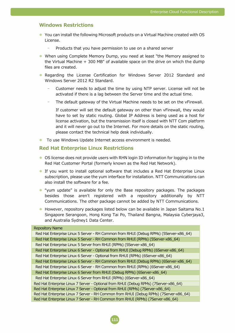
Enterprise Cloud Functional Description
111
Windows Restrictions
You can install the following Microsoft products on a Virtual Machine created with OS
License.
- Products that you have permission to use on a shared server
When using Complete Memory Dump, you need at least "the Memory assigned to
the Virtual Machine + 300 MB" of available space on the drive on which the dump
files are created.
Regarding the License Certification for Windows Server 2012 Standard and
Windows Server 2012 R2 Standard.
- Customer needs to adjust the time by using NTP server. License will not be
activated if there is a lag between the Server time and the actual time.
- The default gateway of the Virtual Machine needs to be set on the vFirewall.
If customer will set the default gateway on other than vFirewall, they would
have to set by static routing. Global IP Address is being used as a host for
license activation, but the transmission itself is closed with NTT Com platform
and it will never go out to the Internet. For more details on the static routing,
please contact the technical help desk individually.
To use Windows Update Internet access environment is needed.
Red Hat Enterprise Linux Restrictions
OS license does not provide users with RHN login ID information for logging in to the
Red Hat Customer Portal (formerly known as the Red Hat Network).
If you want to install optional software that includes a Red Hat Enterprise Linux
subscription, please use the yum interface for installation. NTT Communications can
also install the software for a fee.
“yum update” is available for only the Base repository packages. The packages
besides those aren't registered with a repository additionally by NTT
Communications. The other package cannot be added by NTT Communications.
However, repository packages listed below can be available in Japan Saitama No.1
Singapore Serangoon, Hong Kong Tai Po, Thailand Bangna, Malaysia Cyberjaya3,
and Australia Sydney1 Data Center.
Repository Name
Red Hat Enterprise Linux 5 Server - RH Common from RHUI (Debug RPMs) (5Server-x86_64)
Red Hat Enterprise Linux 5 Server - RH Common from RHUI (RPMs) (5Server-x86_64)
Red Hat Enterprise Linux 5 Server from RHUI (RPMs) (5Server-x86_64)
Red Hat Enterprise Linux 6 Server - Optional from RHUI (Debug RPMs) (6Server-x86_64)
Red Hat Enterprise Linux 6 Server - Optional from RHUI (RPMs) (6Server-x86_64)
Red Hat Enterprise Linux 6 Server - RH Common from RHUI (Debug RPMs) (6Server-x86_64)
Red Hat Enterprise Linux 6 Server - RH Common from RHUI (RPMs) (6Server-x86_64)
Red Hat Enterprise Linux 6 Server from RHUI (Debug RPMs) (6Server-x86_64)
Red Hat Enterprise Linux 6 Server from RHUI (RPMs) (6Server-x86_64)
Red Hat Enterprise Linux 7 Server - Optional from RHUI (Debug RPMs) (7Server-x86_64)
Red Hat Enterprise Linux 7 Server - Optional from RHUI (RPMs) (7Server-x86_64)
Red Hat Enterprise Linux 7 Server - RH Common from RHUI (Debug RPMs) (7Server-x86_64)
Red Hat Enterprise Linux 7 Server - RH Common from RHUI (RPMs) (7Server-x86_64)

Enterprise Cloud Functional Description
112
Red Hat Enterprise Linux 7 Server from RHUI (Debug RPMs) (7Server-x86_64)
Red Hat Enterprise Linux 7 Server from RHUI (RPMs) (7Server-x86_64)
Internet access environment is needed to execute “yum update”. However, for only
VPN Connectivity user in Japan Saitama No.1, Yokohama No.1, Kansai1, Singapore
Serangoon, Hong Kong Tai Po, Thailand Bangna, Malaysia Cyberjaya3, and Australia
Sydney1 Data Center can do “yum update”.
Impementation of package version up (i.e. ver6.2 to 6.5) which executed “yum
upgrade” is not supported.
Precaution about CentOS, Ubuntu
Internet access environment is needed to access repository server.
Precautions about OS License Switch
See Private Catalog section to create a template of virtual servers.
After creating a Virtual Machine at a target of OS License Switch process in the
Enterprise Cloud Service, do not execute Power ON.
OS License Switch does not execute Sysprep. If you want to execute Sysprep,
remake a template from the virtual server after the processing of OS License Switch.
Use the template to create a virtual server. Before its execution, access the
Customer Portal and click on "Change SID" for a startup.
If the customer wants to make application for the processing of OS License Switch
for a virtual server that is turned on (Power ON) before the processing of OS License
Switch or for a Virtual Machine already running, the customer needs to check the
operation in advance before turning off (Power OFF) the Virtual Machine and needs
to make application. While NTT Communications is working on, the Guest OS
customization is executed. For the details, see "About Guest OS Customization"
⇒P.73).
Prohibited Acts
The acts listed below violate the agreement between the user and Microsoft or the
Enterprise Agreement with Red Hat, or are considered incorrect usage as stipulated
in the NTT Communications Service Feature Overview or Conditions for Providing
Services. Users engaged in such acts may be subject to penalties imposed by NTT
Communications such as suspension of service, or incorrect usage penalties imposed
by Microsoft.
The following acts are specific examples. The acts that may be subject to penalties
are not limited to the acts below.
Using licensed products or subscription products provided through OS License
outside of the cloud environment specified by NTT Communications.
Using the Customer Portal features to create and save another template of the
Virtual Machine image, using the export feature to store the template outside of the
NTT Communications cloud environment, creating a new Virtual Machine based on
that file, and running licensed products or subscription products that have been
provided by NTT Communications.

Enterprise Cloud Functional Description
113
Duplicating and using the software without notifying NTT Communications.
Using OS License to duplicate the image of the Virtual Machine that you are running
and then running it as another Virtual Machine without changing the registration
information and without notifying NTT Communications.
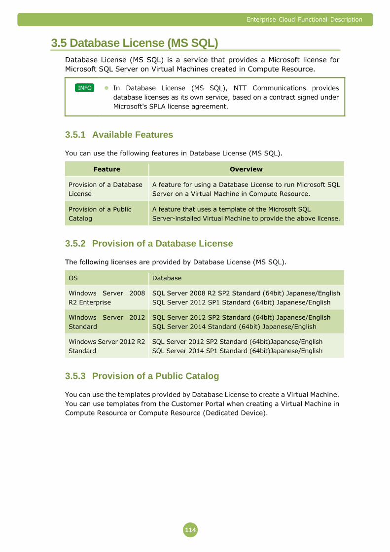
Enterprise Cloud Functional Description
114
3.5 Database License (MS SQL)
Database License (MS SQL) is a service that provides a Microsoft license for
Microsoft SQL Server on Virtual Machines created in Compute Resource.
In Database License (MS SQL), NTT Communications provides
database licenses as its own service, based on a contract signed under
Microsoft's SPLA license agreement.
Available Features 3.5.1
You can use the following features in Database License (MS SQL).
Feature Overview
Provision of a Database
License
A feature for using a Database License to run Microsoft SQL
Server on a Virtual Machine in Compute Resource.
Provision of a Public
Catalog
A feature that uses a template of the Microsoft SQL
Server-installed Virtual Machine to provide the above license.
Provision of a Database License 3.5.2
The following licenses are provided by Database License (MS SQL).
OS Database
Windows Server 2008
R2 Enterprise
SQL Server 2008 R2 SP2 Standard (64bit) Japanese/English
SQL Server 2012 SP1 Standard (64bit) Japanese/English
Windows Server 2012
Standard
SQL Server 2012 SP2 Standard (64bit) Japanese/English
SQL Server 2014 Standard (64bit) Japanese/English
Windows Server 2012 R2
Standard
SQL Server 2012 SP2 Standard (64bit)Japanese/English
SQL Server 2014 SP1 Standard (64bit)Japanese/English
Provision of a Public Catalog 3.5.3
You can use the templates provided by Database License to create a Virtual Machine.
You can use templates from the Customer Portal when creating a Virtual Machine in
Compute Resource or Compute Resource (Dedicated Device).

Enterprise Cloud Functional Description
115
A Database license is only provided for a Virtual Machine created using the provided template (called a "Virtual Machine created with Database License (MS SQL)" below).
One Database License and one OS License are provided as a set for one Virtual Machine created using Database License (MS SQL).
For details regarding the conditions for providing an OS license, refer to "3.4 OS License" (⇒P.107).
SQL Server is installed the first time that you start a Virtual Machine created with Database License (MS SQL). It will therefore take approximately two hours before the login screen is displayed for the first time. Do not perform operations that suspend processing (power off, reset, shutdown, suspend, or restart the Virtual Machine) while you are waiting for the login screen to appear.
Templates exist for each Data Center and are stored in the Public
Catalog, which can be accessed by all users of that Data Center.
Important Points 3.5.4
You cannot save a Virtual Machine created with Database License (MS SQL) to the
Private Catalog in Data Centers where the service for creating a Virtual Machine
from a Private Catalog is not provided.
The Disk capacity required to SQL Server is shown below.
SQL Server Type Required Disk
Capacity
SQL Server 2008 R2 SP2 Standard Japanese 64bit version Approximately 7 GB
SQL Server 2012 SP1 Standard Japanese 64bit version Approximately 13 GB
SQL Server 2012 SP2 Standard Japanese 64bit version Approximately 11GB
SQL Server 2014 Standard Japanese 64bit version Approximately 6GB
SQL Server 2014 SP1 Standard Japanese 64bit version Approximately 9GB
SQL Server 2008 R2 SP2 Standard English 64bit version Approximately 7 GB
SQL Server 2012 SP1 Standard English 64bit version Approximately 13 GB
SQL Server 2012 SP2 Standard English 64bit version Approximately 11GB
SQL Server 2014 Standard English 64bit version Approximately 6GB
SQL Server 2014 SP1 Standard English 64bit version Approximately 9GB
Numbers of vCPUs that can be used with SQL Server Standard Edition comply with
specifications of Microsoft.

Enterprise Cloud Functional Description
116
SQL Server 2008R2
http://msdn.microsoft.com/ja-jp/library/ms143760(v=sql.105).aspx
SQL Server 2012
http://msdn.microsoft.com/ja-jp/library/ms143760(v=sql.110).aspx
SQL Server 2014
http://msdn.microsoft.com/ja-jp/library/ms143760(v=sql.120).aspx
Please set the number of socket under 4 and over 2 cores per socket when over 5
vCPU will be set on Virtual Server.
You cannot change the SQL Server type for a Virtual Machine created with Database
License (MS SQL).
If you reinstall SQL Server, create the Virtual Machine again from the template.
The template specifications may change.
Some initial parameters cannot be changed by Customer.
Prohibited Acts
The acts listed below violate the agreement between the user and Microsoft, or are
considered incorrect usage of NTT Communications services. Users engaged in such
acts may be subject to penalties imposed by NTT Communications such as
suspension of service, or incorrect usage penalties imposed by Microsoft.
The following acts are specific examples. The acts that may be subject to penalties
are not limited to the acts below.
Using licensed products provided through Database License (MS SQL) outside of the
cloud environment specified by NTT Communications.
Using the Customer Portal features to create and save another template of the
Virtual Machine image, using the export feature to store the template outside of the
NTT Communications cloud environment, creating a new Virtual Machine based on
that file, and running licensed products that have been provided by NTT
Communications.
Duplicating and using the software without notifying NTT Communications.
Using Database License (MS SQL) to duplicate the image of the Virtual Machine that
you are running and then running it as another Virtual Machine without notifying
NTT Communications.

Enterprise Cloud Functional Description
117
Initial State of Microsoft SQL Server 3.5.5
For SQL Server 2008 R2 Standard Japanese
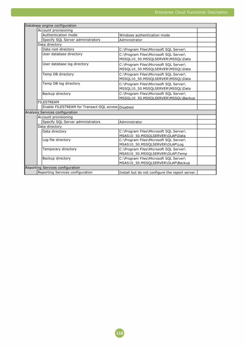
Enterprise Cloud Functional Description
118
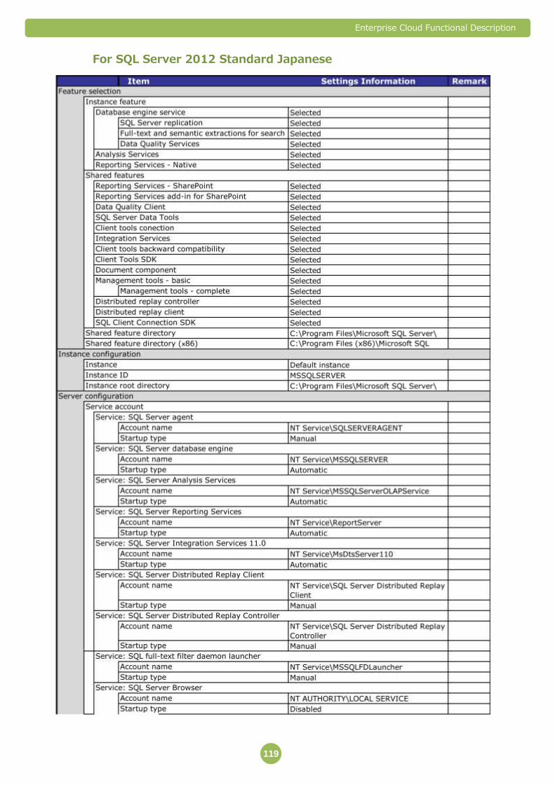
Enterprise Cloud Functional Description
119
For SQL Server 2012 Standard Japanese

Enterprise Cloud Functional Description
120

Enterprise Cloud Functional Description
121
For SQL Server 2008 R2 Standard English
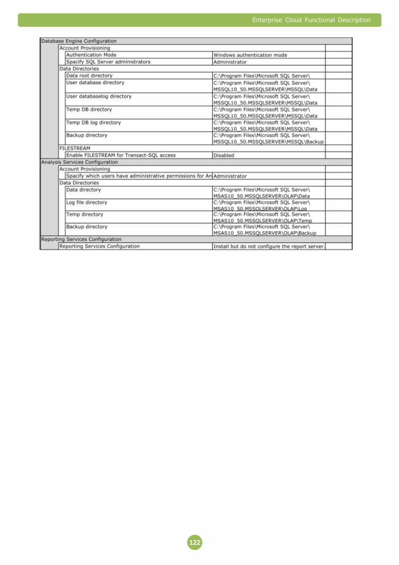
Enterprise Cloud Functional Description
122

Enterprise Cloud Functional Description
123
For SQL Server 2012 Standard English
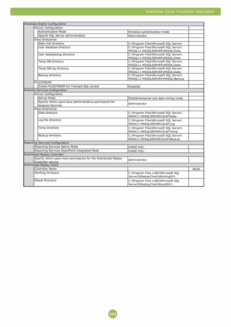
Enterprise Cloud Functional Description
124
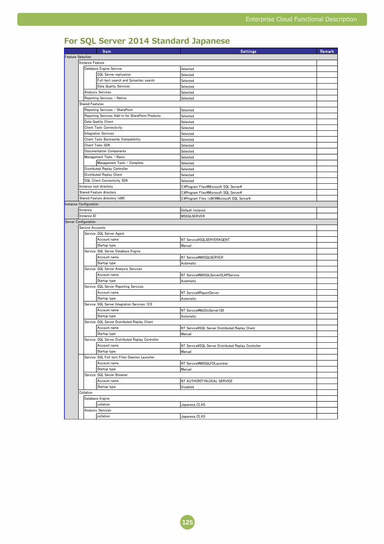
Enterprise Cloud Functional Description
125
For SQL Server 2014 Standard Japanese Item Sett ings Remark
Feature Selection
Instance Feature
Database Engine Service Selected
SQL Server replication Selected
Full-text search and Symantec search Selected
Data Quality Services Selected
Analysis Services Selected
Reporting Services - Native Selected
Shared Features
Reporting Services - SharePoint Selected
Reporting Services Add-in for SharePoint Products Selected
Data Quality Client Selected
Client Tools Connectivity Selected
Integration Services Selected
Client Tools Backwards Compatibility Selected
Client Tools SDK Selected
Documentation Components Selected
Management Tools - Basic Selected
Management Tools - Complete Selected
Distributed Replay Controller Selected
Distributed Replay Client Selected
SQL Client Connectivity SDK Selected
Instance root directory C:\Program Files\Microsoft SQL Server\
Shared Feature directory C:\Program Files\Microsoft SQL Server\
Shared Feature directory (x86) C:\Program Files (x86)\Microsoft SQL Server\
Instance Configuration
Instance Default instance
Instance ID MSSQLSERVER
Server Configuration
Service Accounts
Service:SQL Server Agent
Account name NT Service\SQLSERVERAGENT
Startup type Manual
Service:SQL Server Database Engine
Account name NT Service\MSSQLSERVER
Startup type Automatic
Service:SQL Server Analysis Services
Account name NT Service\MSSQLServerOLAPService
Startup type Automatic
Service:SQL Server Reporting Services
Account name NT Service\ReportServer
Startup type Automatic
Service:SQL Server Integration Services 12.0
Account name NT Service\MsDtsServer120
Startup type Automatic
Service:SQL Server Distributed Replay Client
Account name NT Service\SQL Server Distributed Replay Client
Startup type Manual
Service:SQL Server Distributed Replay Controller
Account name NT Service\SQL Server Distributed Replay Controller
Startup type Manual
Service:SQL Full-text Filter Daemon Launcher
Account name NT Service\MSSQLFDLauncher
Startup type Manual
Service:SQL Server Browser
Account name NT AUTHORITY\LOCAL SERVICE
Startup type Disabled
Collation
Database Engine
collation Japanese_CI_AS
Analysis Services
collation Japanese_CI_AS

Enterprise Cloud Functional Description
126
Database Engine Configuration
Server Configuration
Authentication Mode Windows authentication mode
Specify SQL Server administrators Administrator
Data Directories
Data root directory C:\Program Files\Microsoft SQL Server\
User database directory C:\Program Files\Microsoft SQL Server\MSSQL12.MSSQLSERVER\MSSQL\Data
User databaselog directory C:\Program Files\Microsoft SQL Server\MSSQL12.MSSQLSERVER\MSSQL\Data
Temp DB directory C:\Program Files\Microsoft SQL Server\MSSQL12.MSSQLSERVER\MSSQL\Data
Temp DB log directory C:\Program Files\Microsoft SQL Server\MSSQL12.MSSQLSERVER\MSSQL\Data
Backup directory C:\Program Files\Microsoft SQL Server\MSSQL12.MSSQLSERVER\MSSQL\Backup
FILESTREAM
Enable FILESTREAM for Transact-SQL access Disabled
Analysis Services Configuration
Server Configuration
Server Mode Multidimensional and data mining mode
Spacify which users have administrative permissions for Analysis ServicesAdministrator
Data Directories
Data directory C:\Program Files\Microsoft SQL Server\MSAS12.MSSQLSERVER\OLAP\Data
Log file directory C:\Program Files\Microsoft SQL Server\MSAS12.MSSQLSERVER\OLAP\Log
Temp directory C:\Program Files\Microsoft SQL Server\MSAS12.MSSQLSERVER\OLAP\Temp
Backup directory C:\Program Files\Microsoft SQL Server\MSAS12.MSSQLSERVER\OLAP\Backup
Reporting Services Configuration
Reporting Services Native Mode Install only.
Reporting Services SharePoint Integrated Mode Install only.
Distributed Replay Controller
Spacify which users have permissions for the Distributed Replay Controller service Administrator
Distributed Replay Client
Controller Name Blank
Working Directory C:\Program Files (x86)\Microsoft SQL Server\DReplayClient\WorkingDir\
Result Directory C:\Program Files (x86)\Microsoft SQL Server\DReplayClient\ResultDir\

Enterprise Cloud Functional Description
127
For SQL Server 2014 Standard EnglishItem Sett ings In format ion Remark
Feature Selection
Instance Features
Database Engine Services Selected
SQL Server Replication Selected
Full-Text and Semantic Extractions for Search Selected
Data Quality Services Selected
Analysis Services Selected
Reporting Services - Native Selected
Shared Features
Reporting Services - SharePoint Selected
Reporting Services Add-in for SharePoint Products Selected
Data Quality Client Selected
Client Tools Connectivity Selected
Integration Services Selected
Client Tools Backwards Compatibility Selected
Client Tools SDK Selected
Documentation Components Selected
Management Tools - Basic Selected
Management Tools - Complete Selected
Distributed Replay Controller Selected
Distributed Replay Client Selected
SQL Client Connectivity SDK Selected
Instance root directory C:\Program Files\Microsoft SQL Server\
Shared Feature directory C:\Program Files\Microsoft SQL Server\
Shared Feature directory (x86) C:\Program Files (x86)\Microsoft SQL Server\
Instance Configuration
Instance Default instance
Instance ID MSSQLSERVER
Server Configuration
Service Accounts
Service:SQL Server Agent
Account Name NT Service\SQLSERVERAGENT
Startup Type Manual
Service:SQL Server Database Engine
Account Name NT Service\MSSQLSERVER
Startup Type Automatic
Service:SQL Server Analysis Services
Account Name NT Service\MSSQLServerOLAPService
Startup Type Automatic
Service:SQL Server Reporting Services
Account Name NT Service\ReportServer
Startup Type Automatic
Service:SQL Server Integration Services 12.0
Account Name NT Service\MsDtsServer120
Startup Type Automatic
Service:SQL Server Distributed Replay Client
Account Name NT Service\SQL Server Distributed Replay Client
Startup Type Manual
Service:SQL Server Distributed Replay Controller
Account Name NT Service\SQL Server Distributed Replay Controller
Startup Type Manual
Service:SQL Full-text Filter Daemon Launcher
Account Name NT Service\MSSQLFDLauncher
Startup Type Manual
Service:SQL Server Browser
Account Name NT AUTHORITY\LOCAL SERVICE
Startup Type Disabled
Collation
Database Engine
collation SQL_Latin1_General_CP1_CI_AS
Analysis Services
collation Latin1_General_CI_AS

Enterprise Cloud Functional Description
128
Database Engine Configuration
Server Configuration
Authentication Mode Windows authentication mode
Spacify SQL Server administrators Administrator
Data Directories
Data root directory C:\Program Files\Microsoft SQL Server\
User database directory C:\Program Files\Microsoft SQL Server\MSSQL12.MSSQLSERVER\MSSQL\Data
User databaselog directory C:\Program Files\Microsoft SQL Server\MSSQL12.MSSQLSERVER\MSSQL\Data
Temp DB directory C:\Program Files\Microsoft SQL Server\MSSQL12.MSSQLSERVER\MSSQL\Data
Temp DB log directory C:\Program Files\Microsoft SQL Server\MSSQL12.MSSQLSERVER\MSSQL\Data
Backup directory C:\Program Files\Microsoft SQL Server\MSSQL12.MSSQLSERVER\MSSQL\Backup
FILESTREAM
Enable FILESTREAM for Transact-SQL access Disabled
Analysis Services Configuration
Server Configuration
Server Mode Multidimensional and data mining mode
Spacify which users have administrative permissions for Analysis Services Administrator
Data Directories
Data directory C:\Program Files\Microsoft SQL Server\MSAS12.MSSQLSERVER\OLAP\Data
Log file directory C:\Program Files\Microsoft SQL Server\MSAS12.MSSQLSERVER\OLAP\Log
Temp directory C:\Program Files\Microsoft SQL Server\MSAS12.MSSQLSERVER\OLAP\Temp
Backup directory C:\Program Files\Microsoft SQL Server\MSAS12.MSSQLSERVER\OLAP\Backup
Reporting Services Configuration
Reporting Services Native Mode Install only.
Reporting Services SharePoint Integrated Mode Install only.
Distributed Replay Controller
Spacify which users have permissions for the Distributed Replay Controller service Administrator
Distributed Replay Client
Controller Name Blank
Working Directory C:\Program Files (x86)\Microsoft SQL Server\DReplayClient\WorkingDir\
Result Directory C:\Program Files (x86)\Microsoft SQL Server\DReplayClient\ResultDir\

Enterprise Cloud Functional Description
129
3.6 Database License (Oracle SE One)
Database License (Oracle SE One) Service offers execution environment and license of
Oracle ® Database Standard Edition One (hereafter, “Oracle SE One”), using the
Compute Resource that it manages.
※ Oracle is a registered trademark of Oracle Corporation, its subsidiaries, and
affiliated companies. Company names and product names appearing in this
document may be trademark or registered trademark of the respective companies.
Availabile Features/Services 3.6.1
In this service, the following features/services are available, in addition to the basic
services offered under Enterprise Cloud Service.
Features/Services Description Compute Resource Pool for Oracle Database Virtual Server and Public Catalog
Provides Compute Resource Pools, and Public Catalogs that store Virtual Server Templates for Oracle SE One.
Oracle Database Software License Offers an Oracle Database Standard Edition One License that is necessary for running Oracle SE One
Oracle Database Software Support Provides product support, such as technical inquiry and correction patches regarding Oracle Database Software. If the customer wishes, it also allows searching/viewing of knowledge provided by My Oracle Support, as well as download of correction patches.
Enterprise Cloud Functional Description
130
1) Compute Resource for Oracle Database Virtual Servers, and Public Catalog
Dedicated Compute Resource platform for Oracle SE One (hereafter, SE One
Platform) is provided. Customers can create Compute Resource Pools specifically for
Oracle SE One(hereafter, SE One Resource) on this SE One Platform.
A Public Catalog that stores templates for creating Virtual Servers (hereafter, SE
One Virtual Server) where Oracle Database Software can be installed, is provided.
Customers can use Oracle Database by creating SE One Virtual Server on SE One
Resource.
Creating SE One Virtual Servers on a Compute Resource Pool other than SE One
Resource will be regarded as license violation.
SE One Platform is a single entity (there is only 1 Zone*1). You cannot set multiple
Zones in SE One Resource.
*1 For details about Zone, please refer to “Section 3. Compute Resource”.
SE One Resource can be created by selecting the SE One Resource from “Pool
Management”-“Add Pool”-“Type” from Customer Portal.
Type Guaranteed Compute /Premium Storage/Zone A/Oracle SE ONE※
※ There is a case offered by “Standard Compute/Premium Storage/Zone A/Oracle
SE ONE” by the basis environment.
You can create multiple SE One Virtual Servers, for up to the number preset by the
Enterprise Cloud Service specifications.
Oracle Database installed on SE One Virtual Server includes the latest Patch Set
Release (PSR) at the time of the offering of major version that the customer
specified. Note that Patch Set Update (PSU) or Critical Patch Update (CPU) may be
applied to fix bugs.
Oracle Database package is already installed at the start of the service. Customers
need to access SE One Virtual Server, and create database using Database
Configuration Assistant (DBCA) and Create Database command.
Resources that can be assigned to SE One Virtual Server is preset in Enterprise
Cloud Service. Note an upper limit may apply, depending on the facility that stores
the SE One Platform.
2) Oracle Database Software license
SE One Resource is already applied with an Oracle Database Software license
(Oracle Database Standard Edition One) that NTT Communications obtained from
Oracle Corporation. You do not need to purchase additional Oracle Database
Software Licenses.

Enterprise Cloud Functional Description
131
3) Oracle Database Software Support
NTT Communications provides product support with regard to Oracle Database
Software, including response to technical inquiry and provision of correction patch,
as long as it is within the scope of supporting Oracle Database Software that Oracle
Corporation offers.
To make technical inquiries or requests for correction patch, please use ticket on
Customer Portal.
Installation of correction patch is not included in this service.
When downloading and providing a correction patch, NTT Communications may use
the customer’s SE One Virtual Server account to upload the correction patch.
When downloading and providing a correction patch, NTT Communications may use
the customer’s SE One Virtual Server account to upload the correction patch.
Customers can obtain Support ID that allows them to search/view knowledge, and
download correction patches at My Oracle Support by themselves. To make a
request for Support ID, use Ticket at Customer Portal.
You cannot make Service Request (SR) at My Oracle Support. Please use Ticket at
Customer Portal when you want to inquire about technical issues.
Service Details, and Notes about Use/Design 3.6.2
The followings are details about this service, and things that need to be considered
when creating a system design using the service.
1) Components of the service
To use this service, you will need to apply for the services in the following table.
Service name Function summary Compute Resource Provides SE One Resource necessary for running SE One Virtual
Servers. Compute Class: Guaranteed※ Storage Class: Premium
OS License Provides The OS License and software of SE One Virtual Server Red Hat Enterprise Linux Windows Server (Japanese Data Center only)
※ There is a case offered by Standard Compute by the basis eviroment in Japan Data Center.
2) Oracle software settings
In addition to the parameters specified by the customer, there are following
default/selectable settings in Oracle software. The default settings are fixed and cannot
be changed.

Enterprise Cloud Functional Description
132
Name and version of database software
Items Description
Database software Oracle Database Standard Edition One
Version 11.2.0.4.X※1, 12.1.0.1.X※1
※ ”X” in the version will be changed, and cannot be specified by the customer.
SE One Virtual Server OS
OS name and version
Red Hat Enterprise Linux 6 x86_64 version (64 bit version)
Microsoft Windows Server 2012 R2 Standard x86_64 (64bit)※1 Japanese Data Center only Microsoft Windows Server 2012 Standard x86_64 (64bit)
Microsoft Windows Server 2008 R2 Enterprise x86_64 (64bit)
Red Hat Enterprise Linux 5 x86_64 (64bit)
※Oracle Database Version 12.1.0.1.X is not available in Microsoft Windows Server 2012 R2.
※Timezone is set UTC in Red Hat Enterprise Linux and JST in Microsoft Windows Server.
Oracle Database Software Owner Account
<For Oracle Database 11.2>
Red Hat Enterprise Linux
Oracle Database Software Owner
Account
Group that the account belongs to Remarks
oracle oinstall (Primary Group), dba
Oracle Install User
Microsoft Windows Server
Oracle Database Software Owner
Account
Group that the account belongs to Remarks
oracle Administrators, ora_dba, Users Oracle Install User
<For Oracle Database 12.1>
Red Hat Enterprise Linux
Oracle Database Software Owner
Account
Group that the account belongs to Remarks
oracle oinstall (Primary Group) , dba, oper, backupdba, dgdba, kmdba
Oracle Install User
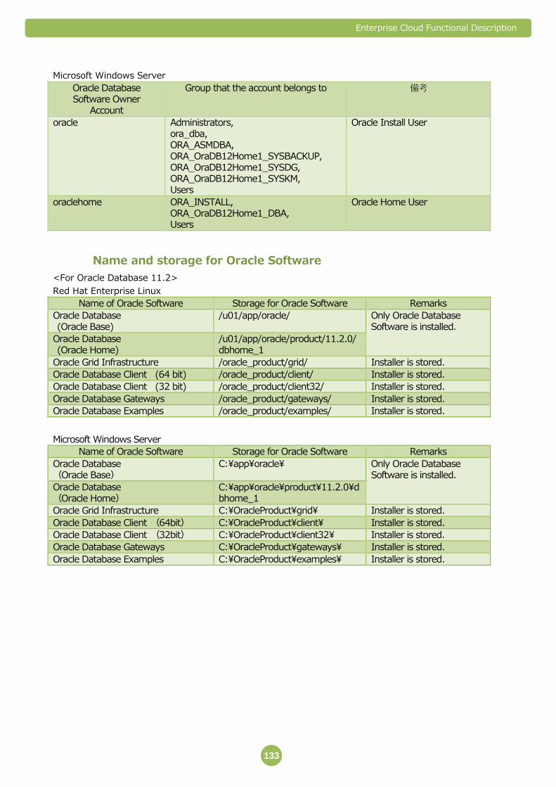
Enterprise Cloud Functional Description
133
Microsoft Windows Server
Oracle Database Software Owner
Account
Group that the account belongs to 備考
oracle Administrators, ora_dba, ORA_ASMDBA, ORA_OraDB12Home1_SYSBACKUP, ORA_OraDB12Home1_SYSDG, ORA_OraDB12Home1_SYSKM, Users
Oracle Install User
oraclehome ORA_INSTALL, ORA_OraDB12Home1_DBA, Users
Oracle Home User
Name and storage for Oracle Software
<For Oracle Database 11.2>
Red Hat Enterprise Linux
Name of Oracle Software Storage for Oracle Software Remarks
Oracle Database (Oracle Base)
/u01/app/oracle/ Only Oracle Database Software is installed.
Oracle Database (Oracle Home)
/u01/app/oracle/product/11.2.0/dbhome_1
Oracle Grid Infrastructure /oracle_product/grid/ Installer is stored.
Oracle Database Client (64 bit) /oracle_product/client/ Installer is stored.
Oracle Database Client (32 bit) /oracle_product/client32/ Installer is stored.
Oracle Database Gateways /oracle_product/gateways/ Installer is stored.
Oracle Database Examples /oracle_product/examples/ Installer is stored.
Microsoft Windows Server
Name of Oracle Software Storage for Oracle Software Remarks
Oracle Database (Oracle Base)
C:\app\oracle\ Only Oracle Database Software is installed.
Oracle Database (Oracle Home)
C:\app\oracle\product\11.2.0\dbhome_1
Oracle Grid Infrastructure C:\OracleProduct\grid\ Installer is stored.
Oracle Database Client (64bit) C:\OracleProduct\client\ Installer is stored.
Oracle Database Client (32bit) C:\OracleProduct\client32\ Installer is stored.
Oracle Database Gateways C:\OracleProduct\gateways\ Installer is stored.
Oracle Database Examples C:\OracleProduct\examples\ Installer is stored.

Enterprise Cloud Functional Description
134
<For Oracle Database 12.1 >
Red Hat Enterprise Linux
Name of Oracle Software Storage for Oracle Software Remarks
Oracle Database (Oracle Base)
/u01/app/oracle/ Only Oracle Database Software is installed.
Oracle Database (Oracle Home)
/u01/app/oracle/product/12.1.0/dbhome_1
Oracle Grid Infrastructure /oracle_product/grid/ Installer is stored.
Oracle Database Client (64 bit) /oracle_product/client/ Installer is stored.
Oracle Database Client (32 bit) /oracle_product/client32/ Installer is stored.
Oracle Database Gateways /oracle_product/gateways/ Installer is stored.
Oracle Database Examples /oracle_product/examples/ Installer is stored.
Oracle Database Global Service Manager
/oracle_product/gsm/ Installer is stored.
Microsoft Windows Server
Name of Oracle Software Storage for Oracle Software Remarks
Oracle Database
(Oracle Base)
C:\app\oraclehome\ Only Oracle Database Software is installed.
Oracle Database
(Oracle Home)
C:\app\oraclehome\product\12.1.0\dbhome_1
Oracle Grid Infrastructure C:\OracleProduct\grid\ Installer is stored.
Oracle Database Client (64bit) C:\OracleProduct\client\ Installer is stored.
Oracle Database Client (32bit) C:\OracleProduct\client32\ Installer is stored.
Oracle Database Gateways C:\OracleProduct\gateways\ Installer is stored.
Oracle Database Examples C:\OracleProduct\examples\ Installer is stored.
Oracle Database Global Service Manager
C:\OracleProduct\gsm\ Installer is stored.
Oracle Fusion Middleware Web Tier Utilities
C:\OracleProduct\ofm_webtier\ Installer is stored.

Enterprise Cloud Functional Description
135
Parameter settings for Oracle Database regarding SE One Virtual
Server OS
<Oracle Database 11.2 and 12.1>
Red Hat Enterprise Linux
Parameter name Value
Kernel parameter
fs.aio-max-nr 1048576
fs.file-max 6815744
kernel.shmall 2097152
kernel.shmmax 536870912
kernel.shmmni 4096
kernel.sem 250 32000 100 128
net.ipv4.ip_local_port_range 9000 65500
net.core.rmem_default 262144
net.core.rmem_max 4194304
net.core.wmem_default 262144
net.core.wmem_max 1048576
Resource restriction parameter for Oracle users
Soft limit on the number of processes that a single user can use (soft nproc) 2047
Hard limit on the number of processes that a single user can use (hard nproc) 16384
Soft limit on the number of open file descriptor (soft nofile) 1024
Hard limit on the number of open file descriptor (hard nofile) 65536
Soft limit on the stack segment size of the process (soft stack) 10240
Microsoft Windows Server
There is no parameter setting for Oracle Database
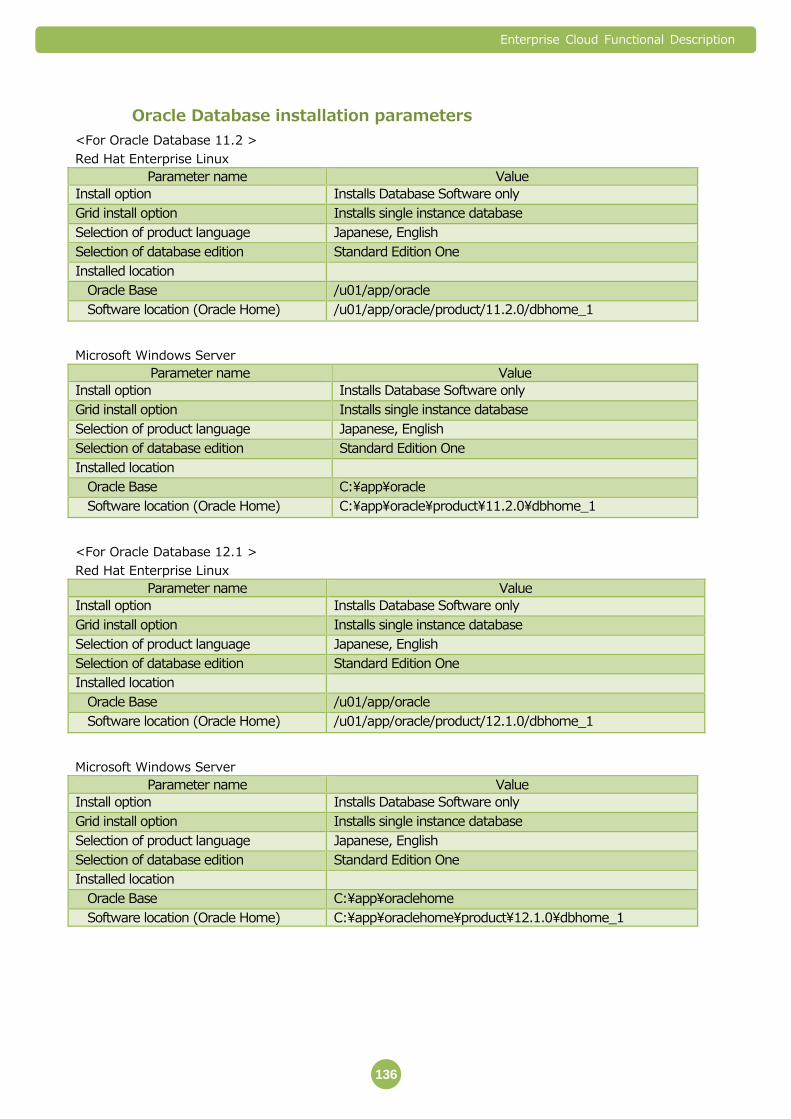
Enterprise Cloud Functional Description
136
Oracle Database installation parameters
<For Oracle Database 11.2 >
Red Hat Enterprise Linux
Parameter name Value
Install option Installs Database Software only
Grid install option Installs single instance database
Selection of product language Japanese, English
Selection of database edition Standard Edition One
Installed location
Oracle Base /u01/app/oracle
Software location (Oracle Home) /u01/app/oracle/product/11.2.0/dbhome_1
Microsoft Windows Server
Parameter name Value
Install option Installs Database Software only
Grid install option Installs single instance database
Selection of product language Japanese, English
Selection of database edition Standard Edition One
Installed location
Oracle Base C:\app\oracle
Software location (Oracle Home) C:\app\oracle\product\11.2.0\dbhome_1
<For Oracle Database 12.1 >
Red Hat Enterprise Linux
Parameter name Value
Install option Installs Database Software only
Grid install option Installs single instance database
Selection of product language Japanese, English
Selection of database edition Standard Edition One
Installed location
Oracle Base /u01/app/oracle
Software location (Oracle Home) /u01/app/oracle/product/12.1.0/dbhome_1
Microsoft Windows Server
Parameter name Value
Install option Installs Database Software only
Grid install option Installs single instance database
Selection of product language Japanese, English
Selection of database edition Standard Edition One
Installed location
Oracle Base C:\app\oraclehome
Software location (Oracle Home) C:\app\oraclehome\product\12.1.0\dbhome_1
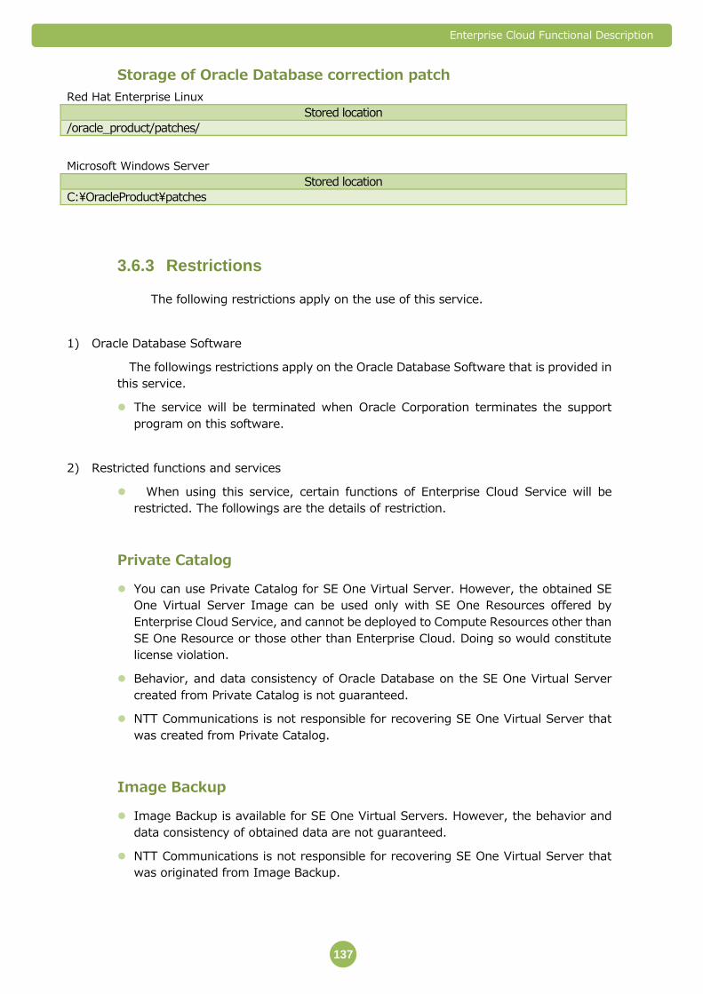
Enterprise Cloud Functional Description
137
Storage of Oracle Database correction patch
Red Hat Enterprise Linux
Stored location
/oracle_product/patches/
Microsoft Windows Server
Stored location
C:\OracleProduct\patches
Restrictions 3.6.3
The following restrictions apply on the use of this service.
1) Oracle Database Software
The followings restrictions apply on the Oracle Database Software that is provided in
this service.
The service will be terminated when Oracle Corporation terminates the support
program on this software.
2) Restricted functions and services
When using this service, certain functions of Enterprise Cloud Service will be
restricted. The followings are the details of restriction.
Private Catalog
You can use Private Catalog for SE One Virtual Server. However, the obtained SE
One Virtual Server Image can be used only with SE One Resources offered by
Enterprise Cloud Service, and cannot be deployed to Compute Resources other than
SE One Resource or those other than Enterprise Cloud. Doing so would constitute
license violation.
Behavior, and data consistency of Oracle Database on the SE One Virtual Server
created from Private Catalog is not guaranteed.
NTT Communications is not responsible for recovering SE One Virtual Server that
was created from Private Catalog.
Image Backup
Image Backup is available for SE One Virtual Servers. However, the behavior and
data consistency of obtained data are not guaranteed.
NTT Communications is not responsible for recovering SE One Virtual Server that
was originated from Image Backup.

Enterprise Cloud Functional Description
138
1) Failure restoration
In the event that SE One Virtual Server malfunctions, NTT Communications
assumes no responsibility for recovering the SE One Virtual Server and all the
installed software and data.
2) Performance assurance
In this service, performance is not guaranteed. Since the service is based on shared
resource, sufficient performance may not be obtained depending on the state of
accommodation.
Operation and maintenance of the service 3.6.4
In this service, operation and maintenance of SE One Virtual Server is supported
in accordance with “Section 8. Maintenance and Operation of Enterprise Cloud
Service (Japan Contract).” In addition, technical inquiries about Oracle products
offered in the service will be accepted, investigated, and replied.
Bring Your Own License (BYOL) for Oracle License 3.6.5
(Japan Contract Only)
Oracle Lisence which Customer owns can be bringed to Enterprise Cloud. It's
possible to be to use BYOL and reduce the charge for Oracle License.
BYOL available Oracle product is below.
- Oracle Database Standard Edition One
Unit of BYOL available Licsence is only “Processor”. Named User Plus (NUP) can not
be available.
Minumum unit of Licence is 1Processor. It is not possible to divide License less than
1.
BYOL available License can be only applied for SE One Resorce. It is not possible to
use other Compute Resource Pool.
BYOL available License cannot use both Enterprise Cloud and others at the same
time.
Charge for the service is calculated by 1 month unit.
The service charge is calculated as follows.
(The total charge for a month) – 16GHz × (montly charge unit) × (the number of
Oracle Processor License)
The reduction upper limit is up to the total charge for a month.
The reduction cannot be carried forward in the next month.

Enterprise Cloud Functional Description
139
Software Update License & Support has to be effective to use BYOL.
NTTCom will confirm the following information at the time of applicate.
- Name of Comute Resource Pool
- Name of Oracle Program
- The number of processor
- PUC number
- Licence type
- License Validity (The start and the end date)
- Contract Name (Company name)
- Oracle License bender name
- Support ID (CSI number)
- Support period (The start and the end date)
Oracle program support is applied to the condition that Customer convenanted with
Oracle Company or Oracle vender before. Please continue and use the support desk.
This is just License birging service. So this means NTTCom does not support
importing Virtual Server image include Oracle which was used in Customer
environment. About the way to import Virtula Server Image, refer to “3.3 Private
Catalog Inport Template Feature” section.
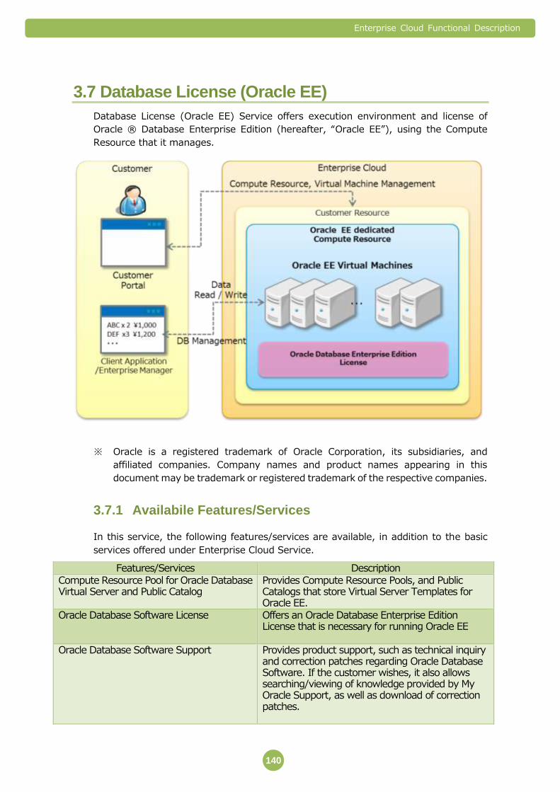
Enterprise Cloud Functional Description
140
3.7 Database License (Oracle EE)
Database License (Oracle EE) Service offers execution environment and license of
Oracle ® Database Enterprise Edition (hereafter, “Oracle EE”), using the Compute
Resource that it manages.
※ Oracle is a registered trademark of Oracle Corporation, its subsidiaries, and
affiliated companies. Company names and product names appearing in this
document may be trademark or registered trademark of the respective companies.
Availabile Features/Services 3.7.1
In this service, the following features/services are available, in addition to the basic
services offered under Enterprise Cloud Service.
Features/Services Description Compute Resource Pool for Oracle Database Virtual Server and Public Catalog
Provides Compute Resource Pools, and Public Catalogs that store Virtual Server Templates for Oracle EE.
Oracle Database Software License Offers an Oracle Database Enterprise Edition License that is necessary for running Oracle EE
Oracle Database Software Support Provides product support, such as technical inquiry and correction patches regarding Oracle Database Software. If the customer wishes, it also allows searching/viewing of knowledge provided by My Oracle Support, as well as download of correction patches.
Enterprise Cloud Functional Description
141
1) Compute Resource for Oracle Database Virtual Servers, and Public Catalog
Dedicated Compute Resource platform for Oracle EE (hereafter, EE Platform) is
provided. Customers can create Compute Resource Pools specifically for Oracle EE
(hereafter, EE Resource) on this EE Platform.
A Public Catalog that stores templates for creating Virtual Servers (hereafter, EE
Virtual Server) where Oracle Database Software can be installed, is provided.
Customers can use Oracle Database by creating EE Virtual Server on EE Resource.
Creating EE Virtual Servers on a Compute Resource Pool other than EE Resource will
be regarded as license violation.
EE Platform is a single entity (there is only 1 Zone*1). You cannot set multiple Zones
in EE Resource.
*1 For details about Zone, please refer to “Section 3. Compute Resource”.
EE Resource can be created by selecting the EE Resource from “Pool
Management”-“Add Pool”-“Type” from Customer Portal.
Type Guaranteed Compute/Premium Storage/Zone A/Oracle EE
You can create multiple EE Virtual Servers, for up to the number preset by the
Enterprise Cloud Service specifications.
Oracle Database installed on EE Virtual Server includes the latest Patch Set Release
(PSR) at the time of the offering of major version that the customer specified. Note
that Patch Set Update (PSU) or Critical Patch Update (CPU) may be applied to fix
bugs.
Oracle Database package is already installed at the start of the service. Customers
need to access EE Virtual Server, and create database using Database Configuration
Assistant (DBCA) and Create Database command.
Resources that can be assigned to EE Virtual Server are preset in Enterprise Cloud
Service. Note an upper limit may apply, depending on the facility that stores the EE
Platform.
2) Oracle Database Software license
EE Resource is already applied with an Oracle Database Software license (Oracle
Database Enterprise Edition) that NTT Communications obtained from Oracle
Corporation. You do not need to purchase additional Oracle Database Software
Licenses.
This service provides only Oracle Database Enterprise Edition. The other option
licenses are not provided. If Customer uses the other opition license, it will be
regarded as license violation.
3) Oracle Database Software Support
NTT Communications provides product support with regard to Oracle Database
Software, including response to technical inquiry and provision of correction patch,

Enterprise Cloud Functional Description
142
as long as it is within the scope of supporting Oracle Database Software that Oracle
Corporation offers.
To make technical inquiries or requests for correction patch, please use ticket on
Customer Portal.
Installation of correction patch is not included in this service.
When downloading and providing a correction patch, NTT Communications may use
the customer’s EE Virtual Server account to upload the correction patch.
When downloading and providing a correction patch, NTT Communications may use
the customer’s EE Virtual Server account to upload the correction patch.
Customers can obtain Support ID that allows them to search/view knowledge, and
download correction patches at My Oracle Support by themselves. To make a
request for Support ID, use Ticket at Customer Portal.
You cannot make Service Request (SR) at My Oracle Support. Please use Ticket at
Customer Portal when you want to inquire about technical issues.
Service Details, and Notes about Use/Design 3.7.2
The followings are details about this service, and things that need to be considered
when creating a system design using the service.
1) Components of the service
To use this service, you will need to apply for the services in the following table.
Service name Function summary Compute Resource Provides EE Resource necessary for running EE Virtual Servers.
Compute Class: Guaranteed Storage Class: Premium
OS License Provides The OS License and software of EE Virtual Server Red Hat Enterprise Linux
2) Oracle software settings
In addition to the parameters specified by the customer, there are following
default/selectable settings in Oracle software. The default settings are fixed and cannot
be changed.
Name and version of database software
Items Description
Database software Oracle Database Enterprise Edition One
Version 11.2.0.4.X※1, 12.1.0.2.X※1
※1 ”X” in the version will be changed, and cannot be specified by the customer.
EE Virtual Server OS
OS name and version
Red Hat Enterprise Linux 6 x86_64 version (64 bit version)
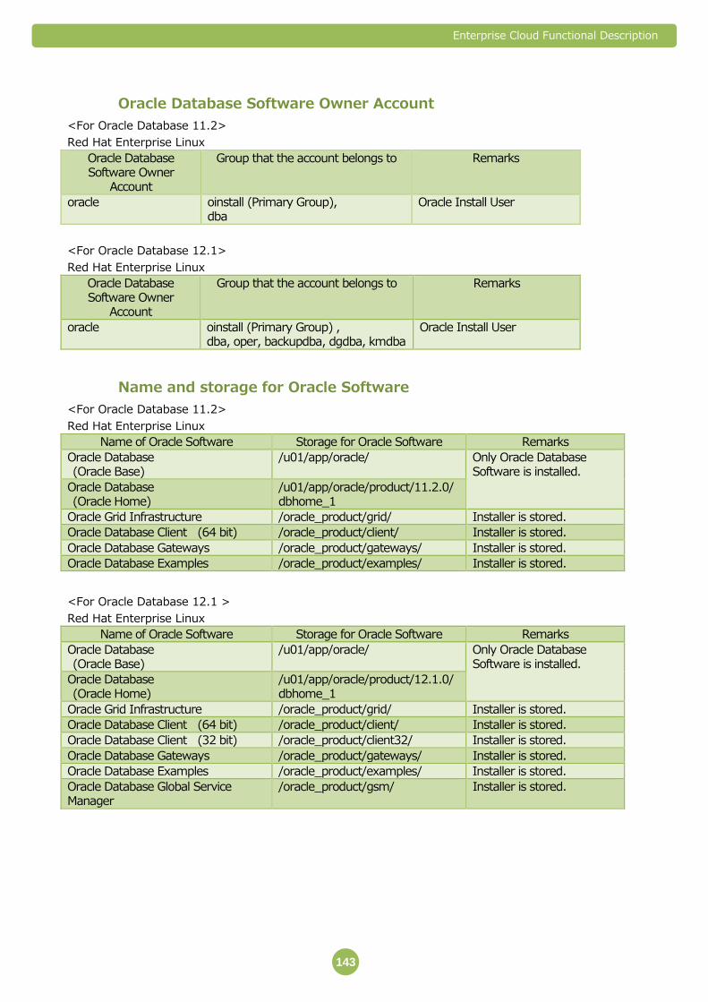
Enterprise Cloud Functional Description
143
Oracle Database Software Owner Account
<For Oracle Database 11.2>
Red Hat Enterprise Linux
Oracle Database Software Owner
Account
Group that the account belongs to Remarks
oracle oinstall (Primary Group), dba
Oracle Install User
<For Oracle Database 12.1>
Red Hat Enterprise Linux
Oracle Database Software Owner
Account
Group that the account belongs to Remarks
oracle oinstall (Primary Group) , dba, oper, backupdba, dgdba, kmdba
Oracle Install User
Name and storage for Oracle Software
<For Oracle Database 11.2>
Red Hat Enterprise Linux
Name of Oracle Software Storage for Oracle Software Remarks
Oracle Database (Oracle Base)
/u01/app/oracle/ Only Oracle Database Software is installed.
Oracle Database (Oracle Home)
/u01/app/oracle/product/11.2.0/dbhome_1
Oracle Grid Infrastructure /oracle_product/grid/ Installer is stored.
Oracle Database Client (64 bit) /oracle_product/client/ Installer is stored.
Oracle Database Gateways /oracle_product/gateways/ Installer is stored.
Oracle Database Examples /oracle_product/examples/ Installer is stored.
<For Oracle Database 12.1 >
Red Hat Enterprise Linux
Name of Oracle Software Storage for Oracle Software Remarks
Oracle Database (Oracle Base)
/u01/app/oracle/ Only Oracle Database Software is installed.
Oracle Database (Oracle Home)
/u01/app/oracle/product/12.1.0/dbhome_1
Oracle Grid Infrastructure /oracle_product/grid/ Installer is stored.
Oracle Database Client (64 bit) /oracle_product/client/ Installer is stored.
Oracle Database Client (32 bit) /oracle_product/client32/ Installer is stored.
Oracle Database Gateways /oracle_product/gateways/ Installer is stored.
Oracle Database Examples /oracle_product/examples/ Installer is stored.
Oracle Database Global Service Manager
/oracle_product/gsm/ Installer is stored.

Enterprise Cloud Functional Description
144
Parameter settings for Oracle Database regardingEE Virtual Server
OS
<Oracle Database 11.2 and 12.1>
Red Hat Enterprise Linux
Parameter name Value
Kernel parameter
fs.aio-max-nr 1048576
fs.file-max 6815744
kernel.shmall 2097152
kernel.shmmax 536870912
kernel.shmmni 4096
kernel.sem 250 32000 100 128
net.ipv4.ip_local_port_range 9000 65500
net.core.rmem_default 262144
net.core.rmem_max 4194304
net.core.wmem_default 262144
net.core.wmem_max 1048576
Resource restriction parameter for Oracle users
Soft limit on the number of processes that a single user can use (soft nproc) 2047
Hard limit on the number of processes that a single user can use (hard nproc) 16384
Soft limit on the number of open file descriptor (soft nofile) 1024
Hard limit on the number of open file descriptor (hard nofile) 65536
Soft limit on the stack segment size of the process (soft stack) 10240
Oracle Database installation parameters
<For Oracle Database 11.2 >
Red Hat Enterprise Linux
Parameter name Value
Install option Installs Database Software only
Grid install option Installs single instance database
Selection of product language Japanese, English
Selection of database edition Enterprise Edition
Installed location
Oracle Base /u01/app/oracle
Software location (Oracle Home) /u01/app/oracle/product/11.2.0/dbhome_1
<For Oracle Database 12.1 >
Red Hat Enterprise Linux
Parameter name Value
Install option Installs Database Software only
Grid install option Installs single instance database
Selection of product language Japanese, English
Selection of database edition Enterprise Edition
Installed location
Oracle Base /u01/app/oracle
Software location (Oracle Home) /u01/app/oracle/product/12.1.0/dbhome_1
Enterprise Cloud Functional Description
145
Storage of Oracle Database correction patch
Red Hat Enterprise Linux
Stored location
/oracle_product/patches/
Restrictions 3.7.3
The following restrictions apply on the use of this service.
1) Oracle Database Software
The followings restrictions apply on the Oracle Database Software that is provided in
this service.
The service will be terminated when Oracle Corporation terminates the support
program on this software.
2) Restricted functions and services
When using this service, certain functions of Enterprise Cloud Service will be
restricted. The followings are the details of restriction.
Private Catalog
You can use Private Catalog for EE Virtual Server. However, the obtained EE Virtual
Server Image can be used only with EE Resources offered by Enterprise Cloud
Service, and cannot be deployed to Compute Resources other than EE Resource or
those other than Enterprise Cloud. Doing so would constitute license violation.
Behavior, and data consistency of Oracle Database on the EE Virtual Server created
from Private Catalog is not guaranteed.
NTT Communications is not responsible for recovering EE Virtual Server that was
created from Private Catalog.
Image Backup
Image Backup is available for EE Virtual Servers. However, the behavior and data
consistency of obtained data are not guaranteed.
NTT Communications is not responsible for recovering EE Virtual Server that was
originated from Image Backup.
1) Failure restoration
In the event that EE Virtual Server malfunctions, NTT Communications assumes no
responsibility for recovering the EE Virtual Server and all the installed software and
data.

Enterprise Cloud Functional Description
146
2) Performance assurance
In this service, performance is not guaranteed. Since the service is based on shared
resource, sufficient performance may not be obtained depending on the state of
accommodation.
Operation and maintenance of the service 3.7.4
In this service, operation and maintenance of EE Virtual Server is supported in
accordance with “Section 8. Maintenance and Operation of Enterprise Cloud Service
(Japan Contract).” In addition, technical inquiries about Oracle products offered in
the service will be accepted, investigated, and replied.
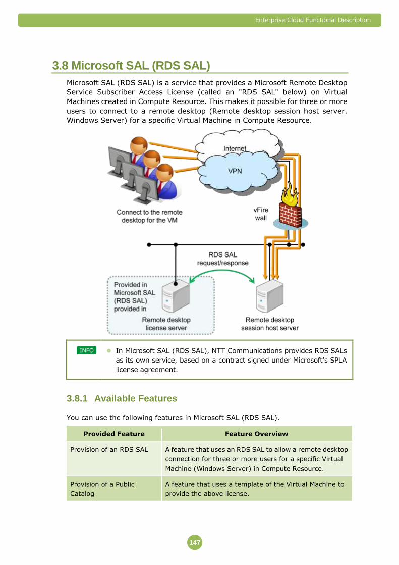
Enterprise Cloud Functional Description
147
3.8 Microsoft SAL (RDS SAL)
Microsoft SAL (RDS SAL) is a service that provides a Microsoft Remote Desktop
Service Subscriber Access License (called an "RDS SAL" below) on Virtual
Machines created in Compute Resource. This makes it possible for three or more
users to connect to a remote desktop (Remote desktop session host server.
Windows Server) for a specific Virtual Machine in Compute Resource.
In Microsoft SAL (RDS SAL), NTT Communications provides RDS SALs
as its own service, based on a contract signed under Microsoft's SPLA
license agreement.
Available Features 3.8.1
You can use the following features in Microsoft SAL (RDS SAL).
Provided Feature Feature Overview
Provision of an RDS SAL A feature that uses an RDS SAL to allow a remote desktop
connection for three or more users for a specific Virtual
Machine (Windows Server) in Compute Resource.
Provision of a Public
Catalog
A feature that uses a template of the Virtual Machine to
provide the above license.

Enterprise Cloud Functional Description
148
Provision of an RDS SAL 3.8.2
The RDS SALs provided by Microsoft SAL (RDS SAL) are shown below.
Item Details
Version Windows Server 2008 R2 Remote Desktop Services SAL
Quantity 10, 30, 50, or 100
Type User SAL
It is necessary to match the OS version of Session Host Server and RDS SAL version of
Remote Desktop License Server. As the current RDS SAL version of Remote Desktop
License Server is Windows Server 2008 R2, the only available OS License for Session
Host Server would be “Windows Server 2008 R2.”
Provision of a Public Catalog 3.8.3
You can use the templates provided by the RDS SAL to create a Virtual Machine
(remote desktop license server).
You can use templates from the Customer Portal when creating a Virtual Machine in
Compute Resource or Compute Resource (Dedicated Device).
An RDS SAL is only provided for a Virtual Machine created using the
provided template (called a "Virtual Machine created with Microsoft SAL
(RDS SAL)" below).
One RDS SAL and one OS license are provided as a set for one Virtual
Machine created using Microsoft SAL (RDS SAL).
The OS that is provided in the set is "Windows Server 2008 R2 Enterprise Japanese/English (64 bit version)." For details regarding the conditions for providing an OS license, refer to "3.4 OS License" (⇒P.107).
Templates exist for each Data Center and are stored in the Public
Catalog, which can be accessed by all users of that Data Center.
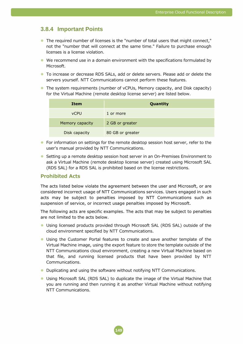
Enterprise Cloud Functional Description
149
Important Points 3.8.4
The required number of licenses is the "number of total users that might connect,"
not the "number that will connect at the same time." Failure to purchase enough
licenses is a license violation.
We recommend use in a domain environment with the specifications formulated by
Microsoft.
To increase or decrease RDS SALs, add or delete servers. Please add or delete the
servers yourself. NTT Communications cannot perform these features.
The system requirements (number of vCPUs, Memory capacity, and Disk capacity)
for the Virtual Machine (remote desktop license server) are listed below.
Item Quantity
vCPU 1 or more
Memory capacity 2 GB or greater
Disk capacity 80 GB or greater
For information on settings for the remote desktop session host server, refer to the
user's manual provided by NTT Communications.
Setting up a remote desktop session host server in an On-Premises Environment to
ask a Virtual Machine (remote desktop license server) created using Microsoft SAL
(RDS SAL) for a RDS SAL is prohibited based on the license restrictions.
Prohibited Acts
The acts listed below violate the agreement between the user and Microsoft, or are
considered incorrect usage of NTT Communications services. Users engaged in such
acts may be subject to penalties imposed by NTT Communications such as
suspension of service, or incorrect usage penalties imposed by Microsoft.
The following acts are specific examples. The acts that may be subject to penalties
are not limited to the acts below.
Using licensed products provided through Microsoft SAL (RDS SAL) outside of the
cloud environment specified by NTT Communications.
Using the Customer Portal features to create and save another template of the
Virtual Machine image, using the export feature to store the template outside of the
NTT Communications cloud environment, creating a new Virtual Machine based on
that file, and running licensed products that have been provided by NTT
Communications.
Duplicating and using the software without notifying NTT Communications.
Using Microsoft SAL (RDS SAL) to duplicate the image of the Virtual Machine that
you are running and then running it as another Virtual Machine without notifying
NTT Communications.
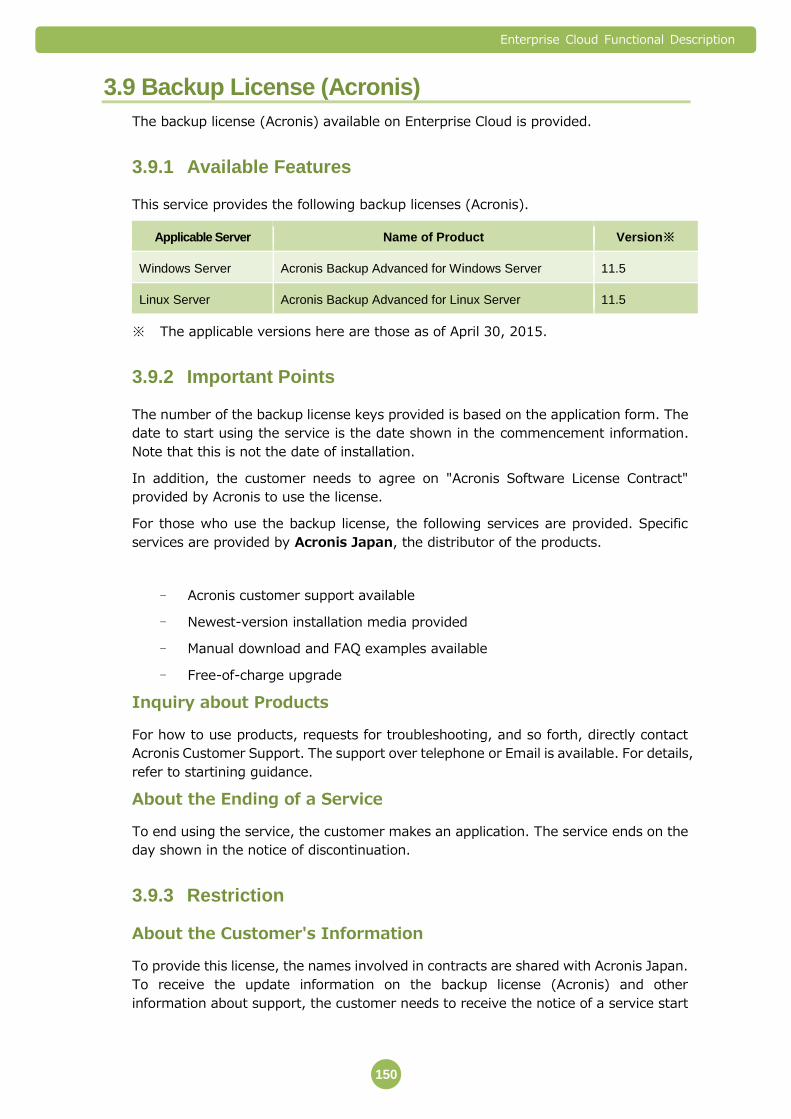
Enterprise Cloud Functional Description
150
3.9 Backup License (Acronis)
The backup license (Acronis) available on Enterprise Cloud is provided.
Available Features 3.9.1
This service provides the following backup licenses (Acronis).
Applicable Server Name of Product Version※
Windows Server Acronis Backup Advanced for Windows Server 11.5
Linux Server Acronis Backup Advanced for Linux Server 11.5
※ The applicable versions here are those as of April 30, 2015.
Important Points 3.9.2
The number of the backup license keys provided is based on the application form. The
date to start using the service is the date shown in the commencement information.
Note that this is not the date of installation.
In addition, the customer needs to agree on "Acronis Software License Contract"
provided by Acronis to use the license.
For those who use the backup license, the following services are provided. Specific
services are provided by Acronis Japan, the distributor of the products.
- Acronis customer support available
- Newest-version installation media provided
- Manual download and FAQ examples available
- Free-of-charge upgrade
Inquiry about Products
For how to use products, requests for troubleshooting, and so forth, directly contact
Acronis Customer Support. The support over telephone or Email is available. For details,
refer to startining guidance.
About the Ending of a Service
To end using the service, the customer makes an application. The service ends on the
day shown in the notice of discontinuation.
Restriction 3.9.3
About the Customer's Information
To provide this license, the names involved in contracts are shared with Acronis Japan.
To receive the update information on the backup license (Acronis) and other
information about support, the customer needs to receive the notice of a service start

Enterprise Cloud Functional Description
151
and to use the Acronis Customer Support shown in the notice of a service start to
register the customer's information.
About the Usage of the License
The following types of use are prohibited.
- To use this license for a virtual server other than the ones for Enterprise Cloud
- To continue to use the license after the day of the end of the service
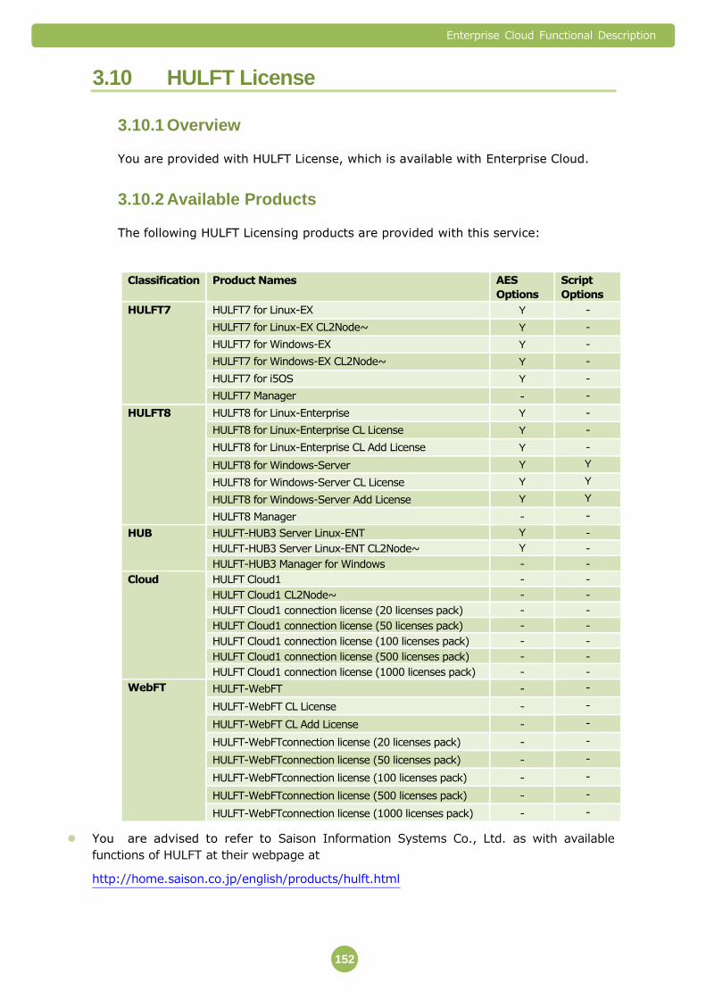
Enterprise Cloud Functional Description
152
3.10 HULFT License
Overview 3.10.1
You are provided with HULFT License, which is available with Enterprise Cloud.
Available Products 3.10.2
The following HULFT Licensing products are provided with this service:
Classification Product Names AES
Options
Script
Options
HULFT7 HULFT7 for Linux-EX Y -
HULFT7 for Linux-EX CL2Node~ Y -
HULFT7 for Windows-EX Y -
HULFT7 for Windows-EX CL2Node~ Y -
HULFT7 for i5OS Y -
HULFT7 Manager - -
HULFT8 HULFT8 for Linux-Enterprise Y -
HULFT8 for Linux-Enterprise CL License Y -
HULFT8 for Linux-Enterprise CL Add License Y -
HULFT8 for Windows-Server Y Y
HULFT8 for Windows-Server CL License Y Y
HULFT8 for Windows-Server Add License Y Y
HULFT8 Manager - -
HUB HULFT-HUB3 Server Linux-ENT Y -
HULFT-HUB3 Server Linux-ENT CL2Node~ Y -
HULFT-HUB3 Manager for Windows - -
Cloud HULFT Cloud1 - -
HULFT Cloud1 CL2Node~ - -
HULFT Cloud1 connection license (20 licenses pack) - -
HULFT Cloud1 connection license (50 licenses pack) - -
HULFT Cloud1 connection license (100 licenses pack) - -
HULFT Cloud1 connection license (500 licenses pack) - -
HULFT Cloud1 connection license (1000 licenses pack) - -
WebFT HULFT-WebFT - -
HULFT-WebFT CL License - -
HULFT-WebFT CL Add License - -
HULFT-WebFTconnection license (20 licenses pack) - -
HULFT-WebFTconnection license (50 licenses pack) - -
HULFT-WebFTconnection license (100 licenses pack) - -
HULFT-WebFTconnection license (500 licenses pack) - -
HULFT-WebFTconnection license (1000 licenses pack) - -
You are advised to refer to Saison Information Systems Co., Ltd. as with available
functions of HULFT at their webpage at
http://home.saison.co.jp/english/products/hulft.html
Enterprise Cloud Functional Description
153
Important Points on Usage & Architecture 3.10.3
You are required to download HULFT modules so that you can install it in Virtual Server.
In order for you to utilize HULFT over Enterprise Cloud, you are advised to confirm
required HULFT user environment (Operating System, Memory, and Disks and so on). As
with required HULFT operational environment, you are required to refer to Saison
Information Systems Co., Ltd. at http://home.saison.co.jp/english/products/hulft.html
Following HULFT License will include the services below in details via Saison Information
Systems Co., Ltd.:
- Usage of HULFT Technical Support Center
- Provisioning of Revised Version at no charge (Except major updates)
- Usage of Technical Support Webpage
Restrictions 3.10.4
Your Private Information
You are hereby advised that your private information attained in provisioning the service
will be shared with Saison Information Systems Co., Ltd. If in any case that you would like
to receive HULFT updates and such information, you are required to register your
information at HULFT Customer Licensing Site noted in the Initial Startup Certificate.
Those who contracted Enterprise Cloud in either of People of Republic of China, Hong
Kong Special Administrative Region of the People's Republic of China, or République
Française, will not be able to purchase and attain HULFT Licensing.
Support Coverage
Following inquiries are to be addressed as specified here:
<Customers who contracted the service in Japan>
Japanese inquiries only; any inquiries through phone-in, Fax, and e-mail are accepted.
Support for products mainly for troubleshooting purposes will be responded for 24-7.
For other inquiries will be covered for support on any business days (from Mondays
through Fridays) from 9:30am through 17:00pm (JST / except national holidays and
Corporate Winter Holiday from December 30th through to the 3rd of January the following
year).
<Customers who contracted the service in country other than Japan>
E-mail inquiries in English only. Inquiries in English will be covered for support on any
business days (from Mondays through Fridays) from 9:30am through 17:00pm (JST /
except national holidays and Corporate Winter Holiday from December 30th through to
the 3rd of January the following year).
Depending upon the users’ Operating System Versions, the service becomes
chargeable. For the details, you are required to inquire your sales in charge.
You are able to peruse the following services: downloading documents, use of
HULFT-FAQ online site, and technical information.
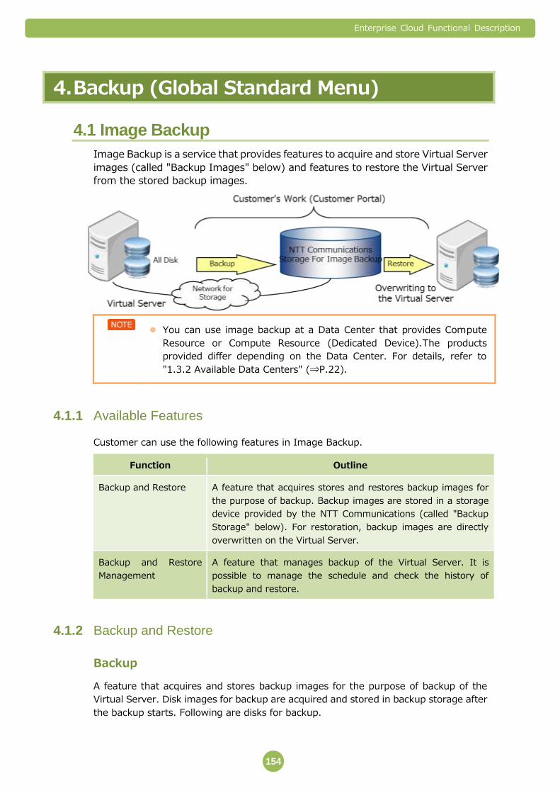
Enterprise Cloud Functional Description
154
4. Backup (Global Standard Menu)
4.1 Image Backup
Image Backup is a service that provides features to acquire and store Virtual Server
images (called "Backup Images" below) and features to restore the Virtual Server
from the stored backup images.
You can use image backup at a Data Center that provides Compute
Resource or Compute Resource (Dedicated Device).The products
provided differ depending on the Data Center. For details, refer to
"1.3.2 Available Data Centers" (⇒P.22).
Available Features 4.1.1
Customer can use the following features in Image Backup.
Function Outline
Backup and Restore A feature that acquires stores and restores backup images for
the purpose of backup. Backup images are stored in a storage
device provided by the NTT Communications (called "Backup
Storage" below). For restoration, backup images are directly
overwritten on the Virtual Server.
Backup and Restore
Management
A feature that manages backup of the Virtual Server. It is
possible to manage the schedule and check the history of
backup and restore.
Backup and Restore 4.1.2
Backup
A feature that acquires and stores backup images for the purpose of backup of the
Virtual Server. Disk images for backup are acquired and stored in backup storage after
the backup starts. Following are disks for backup.

Enterprise Cloud Functional Description
155
All disks for the Virtual Server
Image Backup does not support Virtual Machine which is over 4,000GB for total disk
capacity + the memory resource (different for each Compute Class).
Restore
Backup image is overwritten on and restored from the Virtual Server from which
backup is acquired.
The Virtual Server is restored at the state of Power Off. The Virtual
Server needs to be manually started.
The restored Virtual Server is restored with the following settings for vCPU, memory,
disk and vNIC.
Item Description of setting
vCPU Restores the configuration of the Virtual Server targeted for
backup.
Memory Restores the configuration of the Virtual Server targeted for
backup.
Disk Restores the configuration of the Virtual Server targeted for
backup.
vNIC Restores the vNIC information of the Virtual Server
targeted for backup (IP address, net mask, Mac address).
For various settings of Guest OS, settings of the Virtual Server targeted
for backup are restored, but some setting items including default GW,
subnet mask and DNS are not backed up. For details, refer to "Guest OS
Customization" (⇒P.73).
The "change S-ID" (Sysprep) that is normally performed while using
Windows is not performed.
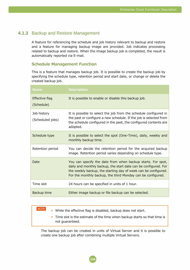
Enterprise Cloud Functional Description
156
Backup and Restore Management 4.1.3
A feature for referencing the schedule and job history relevant to backup and restore
and a feature for managing backup image are provided. Job indicates processing
related to backup and restore. When the image backup job is completed, the result is
automatically reported via E-mail.
Schedule Management Function
This is a feature that manages backup job. It is possible to create the backup job by
specifying the schedule type, retention period and start date, or change or delete the
created backup job.
Name Description
Effective flag
(Schedule)
It is possible to enable or disable this backup job.
Job history
(Scheduled jobs)
It is possible to select the job from the schedule configured in
the past or configure a new schedule. If the job is selected from
the schedule configured in the past, the configured contents are
adopted.
Schedule type It is possible to select the spot (One-Time), daily, weekly and
monthly backup time.
Retention period You can decide the retention period for the acquired backup
image. Retention period varies depending on schedule type.
Date You can specify the date from when backup starts. For spot,
daily and monthly backup, the start date can be configured. For
the weekly backup, the starting day of week can be configured.
For the monthly backup, the third Monday can be configured.
Time slot 24 hours can be specified in units of 1 hour.
Backup time Either image backup or file backup can be selected.
While the effective flag is disabled, backup does not start.
Time slot is the estimate of the time when backup starts so that time is
not guaranteed.
The backup job can be created in units of Virtual Server and it is possible to
create one backup job after combining multiple Virtual Servers.

Enterprise Cloud Functional Description
157
Backup Schedule
With the schedule management function, retention time, date and time slot can be
specified for each schedule type. For backup, only the method that starts the backup at
the specified time slot is available. Time can be specified at the local time when backup
is acquired.
Setting the retention period, date and time slot for each schedule type
Schedule
type
Retention time Date *4 Time slot *2
Spot 1 day, 31 days,
366 days
Specifying the date
(Calendar date)
0 to 1, 1 to 2, 2 to 3, 3 to 4, 4 to
5, 5 to 6, 6 to 7, 7 to 8, 8 to 9, 9
to 10, 10 to 11, 11 to 12
12 to 13, 13 to 14, 14 to 15, 15
to 16, 16 to 17, 17 to 18, 18 to
19
19 to 20, 20 to 21, 21 to 22, 22
to 23, 23 to 24
Daily 1, 2, 3, 4, 5, 6, 7
and 8 days
Specifying the date
(Calendar date)
Weekly 7, 14, 21, 28, 35,
42, 49 and 56 days
Specifying the date
(Specifying the day
of week on which
backup is acquired)
Monthly 31, 62, 93, 124,
155, 186, 217 and
248 days
The specific day is
specified.*1
(Example: Second
Wednesday)
Or the date is
specified (1st to
31st, the last day)
*If the combination between ordinal numbers and day of week is not correct, backup
does not start.
* Specification of date and time slot is dependent on the preconfigured time zone.
Virtual Server Management Function
For the registered Virtual Server, it is possible to check the configuration to
confirm whether the backup job is enabled.
Displaying the History of Backup and Restore
History of execution of backup and restoration is displayed. History is displayed in
order of time when job starts, job type (backup or restore), status
(Success/Failed), execution time and target Virtual Server. Following 2 display
methods: history display for the latest 7 days and all history display.
Backup Image Management and Restore
List of backup image is displayed. The list displays start time, end time, image
size and disk type (all disks). Restore can be executed from the list. Restore is

Enterprise Cloud Functional Description
158
immediately executed. It is also possible to delete the backup image
immediately.
Important Points 4.1.4
A Backup or Restore is failed by use conditions of the foundation. A notice mail is
sent in this case, so please try re execution of Backup or Restore.
Backup Images are not deleted automatically even if the Vitual Server was deleted.
Accounting will be continued until retention time ends in this case, so please be
careful. And if the Virtual Server is deleted in the state for which backup images
were still stored, it is not possible to delete the backup images by Virtual Server
control panel. In this case Virtual Server can be deleted by Image Backup
management panel. For details, refer to “User’s Guide (Image Backup)”.
Backup Image Store
Image backup supports following Guest OS license Virtua Server templates
provided by NTT Communications.
Windows Server 2008 R2 Enterprise
Windows Server 2012 Standard
Windows Server 2012 R2 Standard
Red Hat Enterprise Linux Server 5.8/6.2/6.5/6.7/7.1
The backup image storage capacity is the size of the Disk of the Virtual Server
targeted for backup. It is different from the data capacity written into the backup
storage.
When Virtual Server is deployed from Virtual Server template backup
jobs cannot be set immediately. From a first access to Image Backup
setting display, please wait for about from 2 to 5 hours and set.
The Virtual Server is charged according to disk size.
The starting point of the retention period for backup storage is the start
time of the backup. Charging starts from that point. No fee is charged if
backup fails.
The Backup Image acquisition process is performed independently of whether the
Virtual Server targeted for backup is powered on or off.
During backups, the performance of the Disk I/O of the Virtual Server that is being
backed up might be reduced.
The backup begins within the Time Window you specify. The backup start time
cannot be specified in units of minutes and seconds.
Backup cannot be configured in the last 5 minutes (55 minutes to 0 minute) of the
1-hour time slot for backup. (The alert message appears.)
Enterprise Cloud Functional Description
159
If the number of backup jobs that are performed at the same time in each time slot
exceeds the maximum value, we recommend using the closest available time slot
within the same day or the closest date in the same time slot.
If the Virtual Server targeted for backup has been deleted at the backup start time,
the backup will not be performed.
Disk of the target Virtual Server cannot be extended while performing the backup
process.
To ensure consistency of the file system during backup, we recommend setting
rest points, such as turning OFF the Virtual Server, and performing the backup.
When Virtual Server is shut down by Customer Portal or in Guest OS,
status is change to Partially Powered Off. So please push Power Off
button by Customer Portal mandatory in order to complete to be
powered off.
If the target Virtual Server is restored during the backup, inconsistency in backup
data may occur so do not perform the restore operation during the backup.
When restoring the backup, old root/Admin passwords used when performing the
backup are enabled. Be careful not to forget old passwords because you cannot log
in to the Virtual Server if you do not know these old passwords.
Backup image is stored in the storage for backup during the retention period
specified by customer and the image is deleted when the retention period expires.
The retention period cannot be extended.
Backup image cannot be acquired while External Storage is being mounted. Please
make sure to backup after the unmount. When restoring, please remount again.
The character type which can be used by Friendly Name of Virtual Machine and vApp
is limited to designate by the following. Backup and Restore will be failed in case of
all except for that. Even when a backup is successful, it can't be restored, so please
make a contact to a support desk.
ASCII Charactors Example
Uppercase and lowercase of Alphabet A-Z,a-z
Number 0-9
Backup Image Restore
For restore, backup image is overwritten on and restored from the Virtual Server
from which backup is acquired.
It may take some time for Guest OS Customization at the initial start-up
after the restore. Please start the operation after 15 minutes, once you
have confirmed the status as “Successful” on the Backup Report for the
Customer Portal or received the Restore Completion Mail (If the mail
Enterprise Cloud Functional Description
160
receive setting is valid) Restore operation cannot be performed if the
target Virtual Server is deleted.
Please do not operate the Virtual Machine (such as changing SID etc.) before
the initial power on when restoring. Performance and Statistic Report from
the past will be deleted.
After a restore NIC parameter in Guest OS may be changed. It cannot affect the
communication, but, please contact support desk when there is some
inconvenience.
When disk of Virtual Server under operation is deleted after backup and the disk
contract of Compute Resource is being reduced, please perform restoration after
checking whether the amount of disks required for restoration is secured in
Compute Resource.
Please execute the VM restoration one by one within same Compute Resource Pool.
It is necessary to have free memory and Storage on Compute Resource Pool for
overhead only when restoring. (The overhead is recommended to be max. 20% of
the memory and same volume of the Storage assigned to the Virtual Machine.)
If the IP Address for Virtual Machine is assigned either on vFirewall or vLoad
Balancer, please release the settings of vFirewall or vLoad balancer temporarily and
restore. Please contact the Support Center via Customer Portal ticket, if the
restoration does not complete.
Please do not assign the IP Address of the Virtual Machine used during the Backup to
other Virtual Machines. Restoration will fail due to IP Address duplication.
Backup of Compute Resource (Dedicated Device)
Be careful with the following points when backing up the Virtual Server used by
Compute Resource (Dedicated Device).
For the backup work area, 10% of the Storage Device that is used by Compute
Resource (Dedicated Device) will be used.
During the backup, the performance of the Disk I/O of the Storage Device that is
used by Compute Resource (Dedicated Device) may decrease temporarily.
Backup of Compute Resource (Dedicated Device) may not be supported depending
on usage of disk I/O so please contact us.
License of the Restored Virtual Server
If the Virtual Server targeted for backup was using the OS license provided by NTT
Communications, the overwritten restored license on the Virtual Server is
equivalent to the OS license. Therefore, no OS license is added to the restored
Virtual Server.
Guest OS Setting
When changing the Guest OS network settings, do not disable a vNIC that has been
recognized, even if you are not using that vNIC. If Virtual Servers with disabled vNIC
are backed up and restored, failures might occur.
Enterprise Cloud Functional Description
161
Difference between the Setting Time and Chargeable Duration due
to Difference of Time Zone
Configurable date and time slot are set on the Portal window according to the local time
(configured time zone). However, the system operated with the universal time
coordinated (UTC) so that charging is processed with UTC. For Japan, backup process
that takes a maximum of 9 hours is charged as the process for the previous day.
Example) Charging when backup is performed at the end of month in the Japanese
time zone
To make the explanation easy to understand, Japan Standard Time (JST) is set for time
zone, backup date is set to 0:00 on April 1 (Japan Standard Time) and 0 minute is set
for the backup period.
If the backup retention period is set to one day, the data retention period is set from
0:00 to 23:59 on April 1 in Japan Standard Time. However, if the period is converted
with UTC, the period is converted to (1) 15:00 to 23:59 on March 31 and (2) 00:00 to
14:59 on April 1. Therefore, (1) is processed as the fee for March and (2) is processed
as the fee for April. The time notation in the E-mail about the result of job is UTC.
When Using OS Management
If the OS management service is used, you cannot use the image backup service.
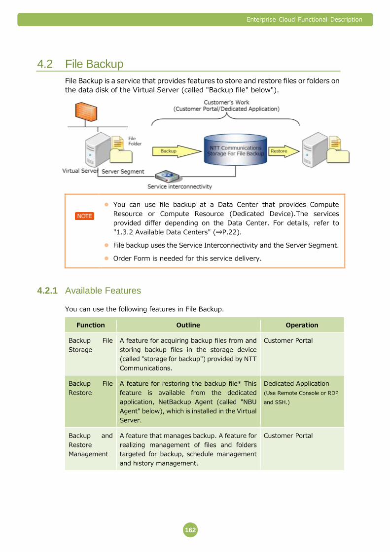
Enterprise Cloud Functional Description
162
4.2 File Backup
File Backup is a service that provides features to store and restore files or folders on
the data disk of the Virtual Server (called "Backup file" below").
You can use file backup at a Data Center that provides Compute
Resource or Compute Resource (Dedicated Device).The services
provided differ depending on the Data Center. For details, refer to
"1.3.2 Available Data Centers" (⇒P.22).
File backup uses the Service Interconnectivity and the Server Segment.
Order Form is needed for this service delivery.
Available Features 4.2.1
You can use the following features in File Backup.
Function Outline Operation
Backup File
Storage
A feature for acquiring backup files from and
storing backup files in the storage device
(called "storage for backup") provided by NTT
Communications.
Customer Portal
Backup File
Restore
A feature for restoring the backup file* This
feature is available from the dedicated
application, NetBackup Agent (called "NBU
Agent" below), which is installed in the Virtual
Server.
Dedicated Application
(Use Remote Console or RDP
and SSH.)
Backup and
Restore
Management
A feature that manages backup. A feature for
realizing management of files and folders
targeted for backup, schedule management
and history management.
Customer Portal

Enterprise Cloud Functional Description
163
Backup File Storage 4.2.2
Backup files are stored in backup storage at the time of start time. Backup file is stored
in the storage for backup during the retention period specified by customer and the file
is automatically deleted when the retention period expires.
Specifying Backup File
When specifying the backup file, Virtual Server needs to be selected and the path of the
file or folder targeted for backup needs to be entered when configuring the backup job
in the Customer Portal.
Encrypting Backup File
The backup file is automatically encrypted by using NBU Agent and the file is stored in
the storage for backup. The encryption key needs to be generated by using NBU Agent.
Encryption cannot be disabled.
If the encryption key is lost, the same encryption needs to be generated again when
restoring the backup file. In this case, the encryption key needs to be generated by
using the same pass phrase as that of the original encryption key.
Keep the pass phrase with care because the backup file cannot be
restored if you forget the pass phrase.
Setting the retention period, date and time slot for each schedule type
Schedule
type
Full backup/
incremental backup
Retention
period
Date *4 Time slot *2
Spot Full backup 1 day, 31 days,
366 days
Specifying the date
(Calendar date)
0 to 3,3 to 6,6 to 9,9 to
12,12 to 15,15 to 18,18 to
21,12 to 24 Daily Full backup
1, 2, 3, 4, 5, 6, 7
and 8 days
Specifying the day of
week (Calendar date)
Weekly (1) Weekly full backup 7, 14, 21, 28, 35,
42 and 56 days
Specifying the date
(Specifying the day of
week on which
backup is acquired) (2) Weekly full backup
+ daily incremental
backup
7, 14, 21, 28, 35,
42 and 56 days
Monthly Full backup 31, 62, 93, 124,
155, 186, 217 and
248 days
The specific day is
specified*1.
(Example: Second
Wednesday)
Or the date is specified
(1st to 31st, the last
day)
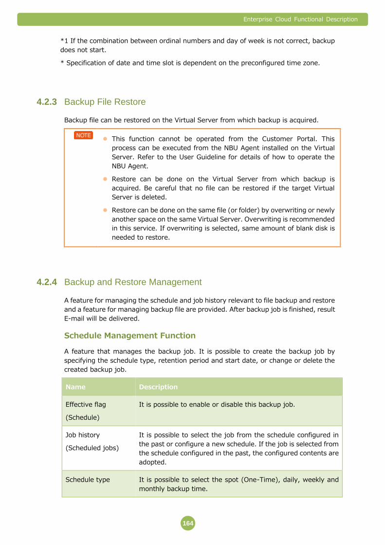
Enterprise Cloud Functional Description
164
*1 If the combination between ordinal numbers and day of week is not correct, backup
does not start.
* Specification of date and time slot is dependent on the preconfigured time zone.
Backup File Restore 4.2.3
Backup file can be restored on the Virtual Server from which backup is acquired.
This function cannot be operated from the Customer Portal. This
process can be executed from the NBU Agent installed on the Virtual
Server. Refer to the User Guideline for details of how to operate the
NBU Agent.
Restore can be done on the Virtual Server from which backup is
acquired. Be careful that no file can be restored if the target Virtual
Server is deleted.
Restore can be done on the same file (or folder) by overwriting or newly
another space on the same Virtual Server. Overwriting is recommended
in this service. If overwriting is selected, same amount of blank disk is
needed to restore.
Backup and Restore Management 4.2.4
A feature for managing the schedule and job history relevant to file backup and restore
and a feature for managing backup file are provided. After backup job is finished, result
E-mail will be delivered.
Schedule Management Function
A feature that manages the backup job. It is possible to create the backup job by
specifying the schedule type, retention period and start date, or change or delete the
created backup job.
Name Description
Effective flag
(Schedule)
It is possible to enable or disable this backup job.
Job history
(Scheduled jobs)
It is possible to select the job from the schedule configured in
the past or configure a new schedule. If the job is selected from
the schedule configured in the past, the configured contents are
adopted.
Schedule type It is possible to select the spot (One-Time), daily, weekly and
monthly backup time.

Enterprise Cloud Functional Description
165
Name Description
Incremental backup* If the weekly backup is selected for the schedule type,
combination with daily incremental backup can be selected.
Retention period You can decide the retention period for the acquired backup
image. Retention period varies depending on schedule type.
Date You can specify the date from when backup starts. For spot,
daily and monthly backup, the start date can be configured. For
the weekly backup, the starting day of week can be configured.
For the monthly backup, the third Monday can be configured.
Time slot 24 hours can be specified in units of 3 hours.
Backup target path Enter the path of the file or folder targeted for backup. Multiple
paths can be described simultaneously by starting new lines.
(Example: /usr/local (for Linux) and c:\Program Files (for
Windows), etc.)
* Although the backup schedule is registered even if the path
that does not exist in the Virtual Server is entered, please note
that backup will not be executed. And if file or folder name is
changed after backup job was set, backup job will not be
executed.
Backup type Either image backup or file backup can be selected.
※ Full backup is executed once a week and daily incremental backup is executed for
backing up images or files added from the previous day. With combination of
weekly full backup and daily incremental backup, usage fee can be saved
compared to the fee charged when full backup is executed every day.
While the effective flag is disabled, backup does not start.
Time slot is the estimate of the time when backup starts so that time is
not guaranteed.
The backup job can be created as one backup job by combining multiple
files and folders existing in a single VM or multiple VMs.
Virtual Server Management Function
For the Virtual Server registered as the target of file backup, it is possible to check the
configurations to confirm whether the backup job is enabled. It is possible to move
from this feature to the schedule management feature and then set a new schedule.
Enterprise Cloud Functional Description
166
Backup History
History of execution of backup is displayed. History is displayed in order of time when
job starts, job type (backup), status (Success/Failed), execution time and target
file/folder. Following 2 display methods: history display for the latest 7 days and all
history display. Restore can be executed only from the NBU Agent installed on the
Virtual Server. Restore history can be displayed by NBU Agent.
Restore Management
The backup file list (start time, end time disk type (all disks)) can be checked and
restored from the NBU Agent. Restore is immediately executed. It is also possible to
delete the backup file immediately.
Important Points 4.2.5
A Backup or Restore is failed by use conditions of the foundation. A notice mail is
sent in this case, so please try re execution of Backup or Restore.
About Application for this Service
To use this service, you must provide information about ID/password with
administrator right or root right for the Virtual Server containing file and folder
targeted for file backup to NTT Communications. NTT Communications use this
information for installing and configuring NBU Agent. Be sure to delete ID or
change password immediately after NBU Agent becomes available.
In addition to installation and configuration of NBU Agent, the work for registering
information of the targeted Virtual Server into the NTT Communications' backup
infrastructure is necessary. Even if the customer configures NBU Agent, this
service is not available until NTT Communications completes the above registration
work.
NTT Communications set up Server Segment for File Backup. If Customer have
already used IP address range below, this service cannot be provided.
- 10.223.112.0/20
Please permit port 1556 for this service. Please refer to following site in case of
Windows Firewall settings.
http://windows.microsoft.com/ja-jp/windows/understanding-firewall-settings#1T
C=windows-7
Please do not change any Server Segment parameter for Filebackup by Customer
Portal.
In Windows Server Registry Key will be added for this service. Please confirm
whether there isn't influence to the system beforehand.
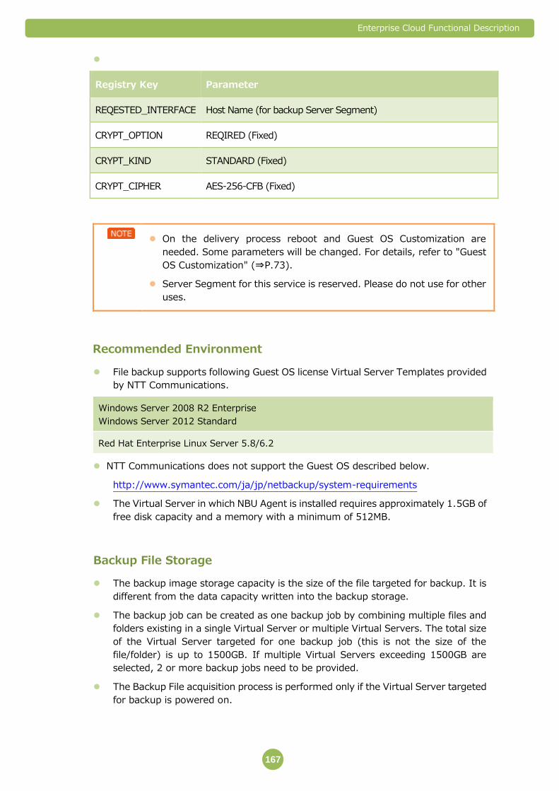
Enterprise Cloud Functional Description
167
Registry Key Parameter
REQESTED_INTERFACE Host Name (for backup Server Segment)
CRYPT_OPTION REQIRED (Fixed)
CRYPT_KIND STANDARD (Fixed)
CRYPT_CIPHER AES-256-CFB (Fixed)
On the delivery process reboot and Guest OS Customization are
needed. Some parameters will be changed. For details, refer to "Guest
OS Customization" (⇒P.73).
Server Segment for this service is reserved. Please do not use for other
uses.
Recommended Environment
File backup supports following Guest OS license Virtual Server Templates provided
by NTT Communications.
Windows Server 2008 R2 Enterprise
Windows Server 2012 Standard
Red Hat Enterprise Linux Server 5.8/6.2
NTT Communications does not support the Guest OS described below.
http://www.symantec.com/ja/jp/netbackup/system-requirements
The Virtual Server in which NBU Agent is installed requires approximately 1.5GB of
free disk capacity and a memory with a minimum of 512MB.
Backup File Storage
The backup image storage capacity is the size of the file targeted for backup. It is
different from the data capacity written into the backup storage.
The backup job can be created as one backup job by combining multiple files and
folders existing in a single Virtual Server or multiple Virtual Servers. The total size
of the Virtual Server targeted for one backup job (this is not the size of the
file/folder) is up to 1500GB. If multiple Virtual Servers exceeding 1500GB are
selected, 2 or more backup jobs need to be provided.
The Backup File acquisition process is performed only if the Virtual Server targeted
for backup is powered on.

Enterprise Cloud Functional Description
168
During backups, the performance of the Disk I/O of the Virtual Server that is being
backed up might be reduced.
The backup begins within the time slot you specify. The backup start time cannot
be specified in units of minutes and seconds.
Backup cannot be configured in the last 5 minutes (55 minutes to 0 minute) of the
3-hour time slot for backup. (The alert message appears.)
If the number of backup jobs that are performed at the same time in each time slot
exceeds the maximum value, we recommend the closest available time slot within
the same day or the closest date in the same time slot.
If the Virtual Server targeted for backup has been deleted at the backup start time,
the backup will not be performed.
Disk of the target Virtual Server cannot be extended while performing the backup
process.
The starting point of the retention period for backup file is the start time of the
backup.
If the target Virtual Server is restored during the backup, inconsistency in backup
data may occur so do not perform the restore operation during the backup.
When backup is acquired periodically, there might be a time period without the
backup file due to the gap between the start time of next backup and retention
period. In order to avoid this situation, one additional day will be added to the
retention period with no charge.
Backup of Compute Resource (Dedicated Device)
Be careful with the following points when performing the file backup for the Virtual
Server used by Compute Resource (Dedicated Device).
During the backup, the performance of the Disk I/O of the Storage Device that is
used by Compute Resource (Dedicated Device) may decrease temporarily.
Backup of Compute Resource (Dedicated Device) may not be supported depending
on usage of disk I/O. In this case, please contact our Support Center.
Difference between the Setting Time and Chargeable Duration due
to Difference of Time Zone
Configurable date and time slot are set on the Portal window according to the local time
(configured time zone). However, fee is charged based on the universal time
coordinated (UTC) in consideration of specifications of the service. For Japan, backup
process that takes a maximum of 9 hours is charged as the process for the previous day
due to a time difference.
Example) Charging when backup is performed at the end of month in the Japanese
time zone
Japan Standard Time (JST) is set for time zone; backup date is set to 0:00 on April 1
(Japan Standard Time) and 0 minute is set for the backup period.

Enterprise Cloud Functional Description
169
If the backup retention period is set to one day, the data retention period is set from
0:00 to 23:59 on April 1 in Japan Standard Time. However, if the period is converted
with UTC, the period is converted to (1) 15:00 to 23:59 on March 31 and (2) 00:00 to
14:59 on April 1. Therefore, (1) is processed as the fee for March and (2) is processed
as the fee for April.
A half-width kana character cannot be specified in backup and
restore. (Japan only)
The file and folder using a half-width kana character cannot be backed up.
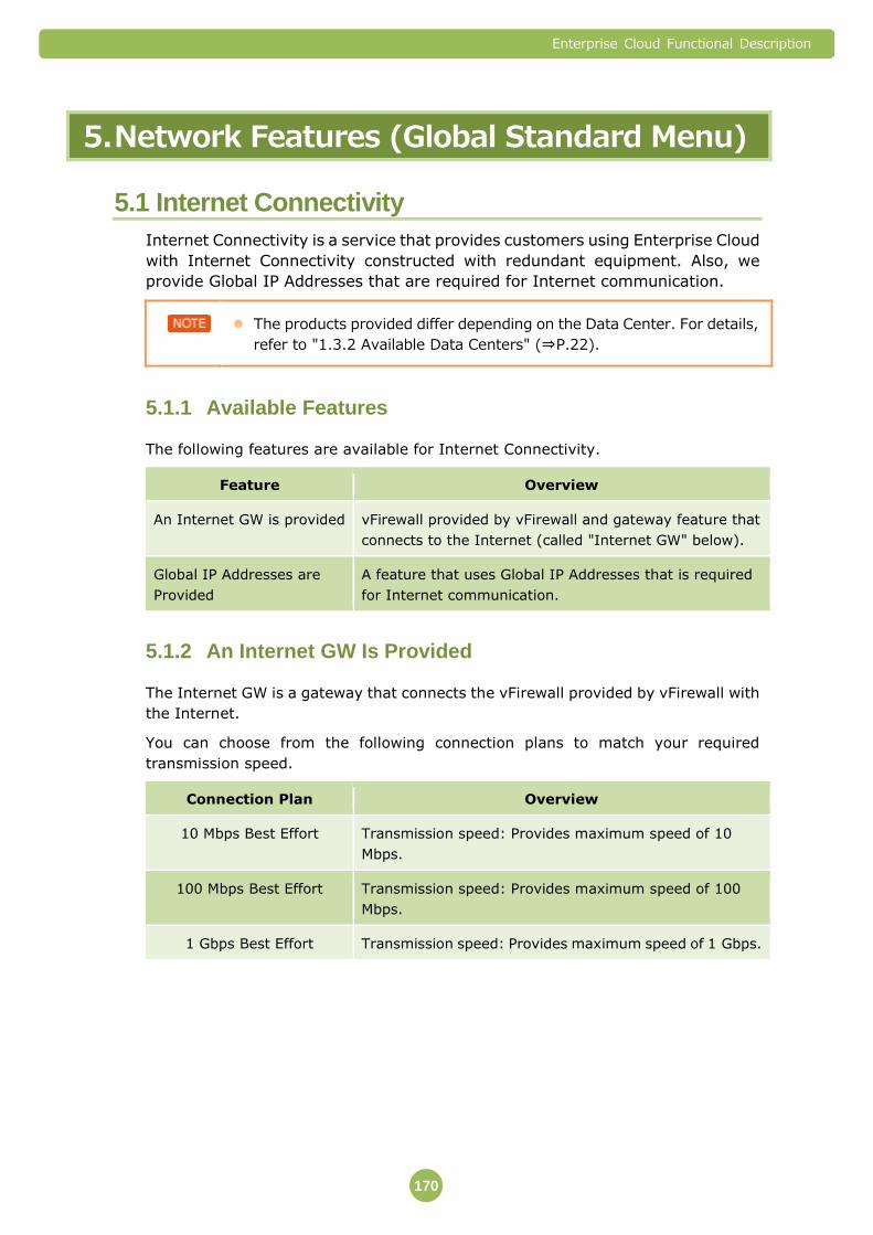
Enterprise Cloud Functional Description
170
5. Network Features (Global Standard Menu)
5.1 Internet Connectivity
Internet Connectivity is a service that provides customers using Enterprise Cloud
with Internet Connectivity constructed with redundant equipment. Also, we
provide Global IP Addresses that are required for Internet communication.
The products provided differ depending on the Data Center. For details,
refer to "1.3.2 Available Data Centers" (⇒P.22).
Available Features 5.1.1
The following features are available for Internet Connectivity.
Feature Overview
An Internet GW is provided vFirewall provided by vFirewall and gateway feature that
connects to the Internet (called "Internet GW" below).
Global IP Addresses are
Provided
A feature that uses Global IP Addresses that is required
for Internet communication.
An Internet GW Is Provided 5.1.2
The Internet GW is a gateway that connects the vFirewall provided by vFirewall with
the Internet.
You can choose from the following connection plans to match your required
transmission speed.
Connection Plan Overview
10 Mbps Best Effort Transmission speed: Provides maximum speed of 10
Mbps.
100 Mbps Best Effort Transmission speed: Provides maximum speed of 100
Mbps.
1 Gbps Best Effort Transmission speed: Provides maximum speed of 1 Gbps.
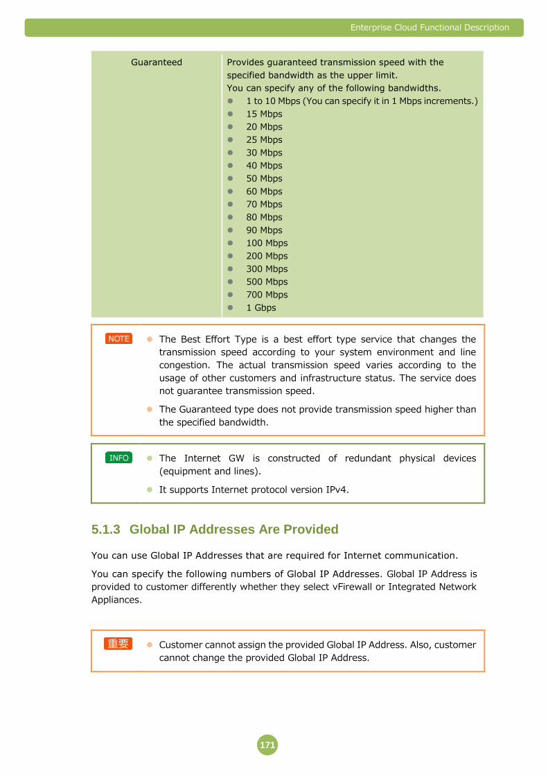
Enterprise Cloud Functional Description
171
Guaranteed Provides guaranteed transmission speed with the
specified bandwidth as the upper limit.
You can specify any of the following bandwidths.
1 to 10 Mbps (You can specify it in 1 Mbps increments.)
15 Mbps
20 Mbps
25 Mbps
30 Mbps
40 Mbps
50 Mbps
60 Mbps
70 Mbps
80 Mbps
90 Mbps
100 Mbps
200 Mbps
300 Mbps
500 Mbps
700 Mbps
1 Gbps
The Best Effort Type is a best effort type service that changes the
transmission speed according to your system environment and line
congestion. The actual transmission speed varies according to the
usage of other customers and infrastructure status. The service does
not guarantee transmission speed.
The Guaranteed type does not provide transmission speed higher than
the specified bandwidth.
The Internet GW is constructed of redundant physical devices
(equipment and lines).
It supports Internet protocol version IPv4.
Global IP Addresses Are Provided 5.1.3
You can use Global IP Addresses that are required for Internet communication.
You can specify the following numbers of Global IP Addresses. Global IP Address is
provided to customer differently whether they select vFirewall or Integrated Network
Appliances.
Customer cannot assign the provided Global IP Address. Also, customer
cannot change the provided Global IP Address.
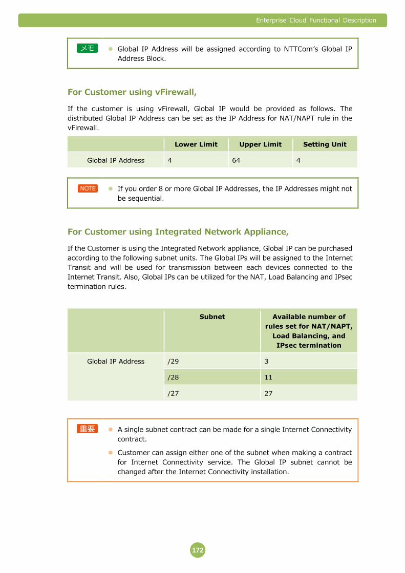
Enterprise Cloud Functional Description
172
Global IP Address will be assigned according to NTTCom’s Global IP
Address Block.
For Customer using vFirewall,
If the customer is using vFirewall, Global IP would be provided as follows. The
distributed Global IP Address can be set as the IP Address for NAT/NAPT rule in the
vFirewall.
Lower Limit Upper Limit Setting Unit
Global IP Address 4 64 4
If you order 8 or more Global IP Addresses, the IP Addresses might not
be sequential.
For Customer using Integrated Network Appliance,
If the Customer is using the Integrated Network appliance, Global IP can be purchased
according to the following subnet units. The Global IPs will be assigned to the Internet
Transit and will be used for transmission between each devices connected to the
Internet Transit. Also, Global IPs can be utilized for the NAT, Load Balancing and IPsec
termination rules.
Subnet Available number of
rules set for NAT/NAPT,
Load Balancing, and
IPsec termination
Global IP Address /29 3
/28 11
/27 27
A single subnet contract can be made for a single Internet Connectivity
contract.
Customer can assign either one of the subnet when making a contract
for Internet Connectivity service. The Global IP subnet cannot be
changed after the Internet Connectivity installation.

Enterprise Cloud Functional Description
173
Important Points 5.1.4
Restrictions When Connecting to the Internet
Internet Connectivity is a service in which multiple customers share the Internet
lines that are made available by NTT Communications. Internet lines that are
provided by the customer cannot be used.
Bandwidths specified with the Guaranteed type are guaranteed for all the Global IP
Addresses provided. You cannot specify IP Addresses and guarantee the bandwidth.
The Guaranteed type only guarantees the communication bandwidths that pass
through the Internet GW. In order to guarantee the communication bandwidth that
the vFirewall and vLoad Balancer pass through, it is necessary to have separate
contracts for a suitable number of firewall resources and load balancer resources.
Communication interruptions might occur when Internet Connectivity settings are
changed.
This service does not provide DNS resolver. Please prepare DNS by Customer.
The DNS resolver is not offered with this service. Customer needs to prepare.
Restrictions on Placing Orders
If you are using DDoS Solution Service (J030801) at Yokohama No.1 Data Center,
you cannot use a plan higher than 1 Gbps Best Effort type or 200 Mbps Guaranteed
Band type.
※ DDos Solution Service is a service that is unique to Japan Data Centers
(Local Option Menu).

Enterprise Cloud Functional Description
174
5.2 VPN Connectivity
VPN Connectivity provides a connection to Arcstar Universal One Service (NTT
Communications VPN service). The function of plan change and routing setting
and Ping is available on the Customer Portal the service released Data Center.
Available Features 5.2.1
The following features are available for VPN Connectivity.
Feature Overview
VPN Gateway A gateway feature (called "VPN Gateway" below) that
connects Arcstar Universal One Service to vFirewall or
Integrated Network Appliance.
VPN Routing Settings A feature that sets up routing to enable communication
between Arcstar Universal One Service and vFirewall or
Integrated Network Appliance.
Ping Ping function in VPN Gateway
※ Arcstar IP-VPN Service can be available via Universal One using “Arcster Universal
One Connectivity Service”.
VPN Gateway 5.2.2
The VPN Connectivity GW is a gateway that connects Arcstar Universal One Service
to vFirewall or Integrated Network Appliance.
You can choose from the following connection plans to match your required
transmission speed.
Connection Plan Overview
100 Mbps Best Effort Transmission speed: Provides maximum uplink speed of
100 Mbps and maximum downlink speed of 100 Mbps.
Guaranteed Provides guaranteed transmission speed with the
specified bandwidth (uplink/downlink) as the upper limit.
You can specify any of the following bandwidths.
100 Mbps
200 Mbps
1 Gbps
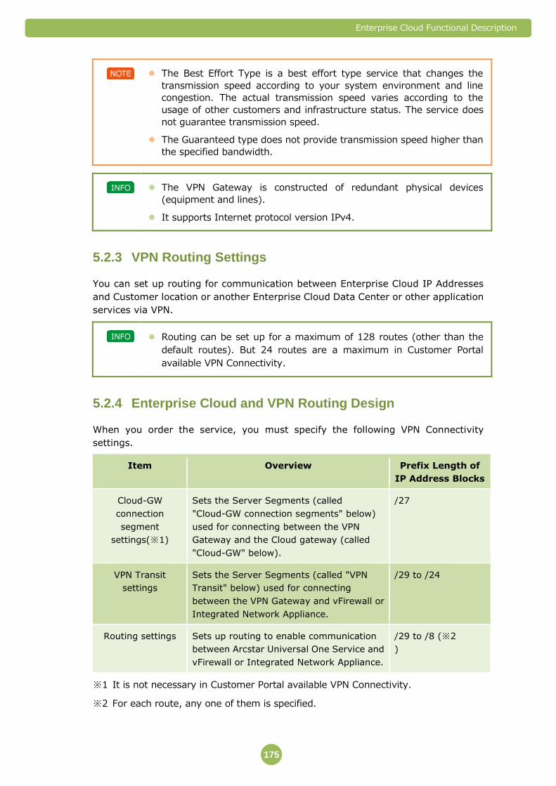
Enterprise Cloud Functional Description
175
The Best Effort Type is a best effort type service that changes the
transmission speed according to your system environment and line
congestion. The actual transmission speed varies according to the
usage of other customers and infrastructure status. The service does
not guarantee transmission speed.
The Guaranteed type does not provide transmission speed higher than
the specified bandwidth.
The VPN Gateway is constructed of redundant physical devices
(equipment and lines).
It supports Internet protocol version IPv4.
VPN Routing Settings 5.2.3
You can set up routing for communication between Enterprise Cloud IP Addresses
and Customer location or another Enterprise Cloud Data Center or other application
services via VPN.
Routing can be set up for a maximum of 128 routes (other than the
default routes). But 24 routes are a maximum in Customer Portal
available VPN Connectivity.
Enterprise Cloud and VPN Routing Design 5.2.4
When you order the service, you must specify the following VPN Connectivity
settings.
Item Overview Prefix Length of
IP Address Blocks
Cloud-GW
connection
segment
settings(※1)
Sets the Server Segments (called
"Cloud-GW connection segments" below)
used for connecting between the VPN
Gateway and the Cloud gateway (called
"Cloud-GW" below).
/27
VPN Transit
settings
Sets the Server Segments (called "VPN
Transit" below) used for connecting
between the VPN Gateway and vFirewall or
Integrated Network Appliance.
/29 to /24
Routing settings Sets up routing to enable communication
between Arcstar Universal One Service and
vFirewall or Integrated Network Appliance.
/29 to /8 (※2
)
※1 It is not necessary in Customer Portal available VPN Connectivity.
※2 For each route, any one of them is specified.
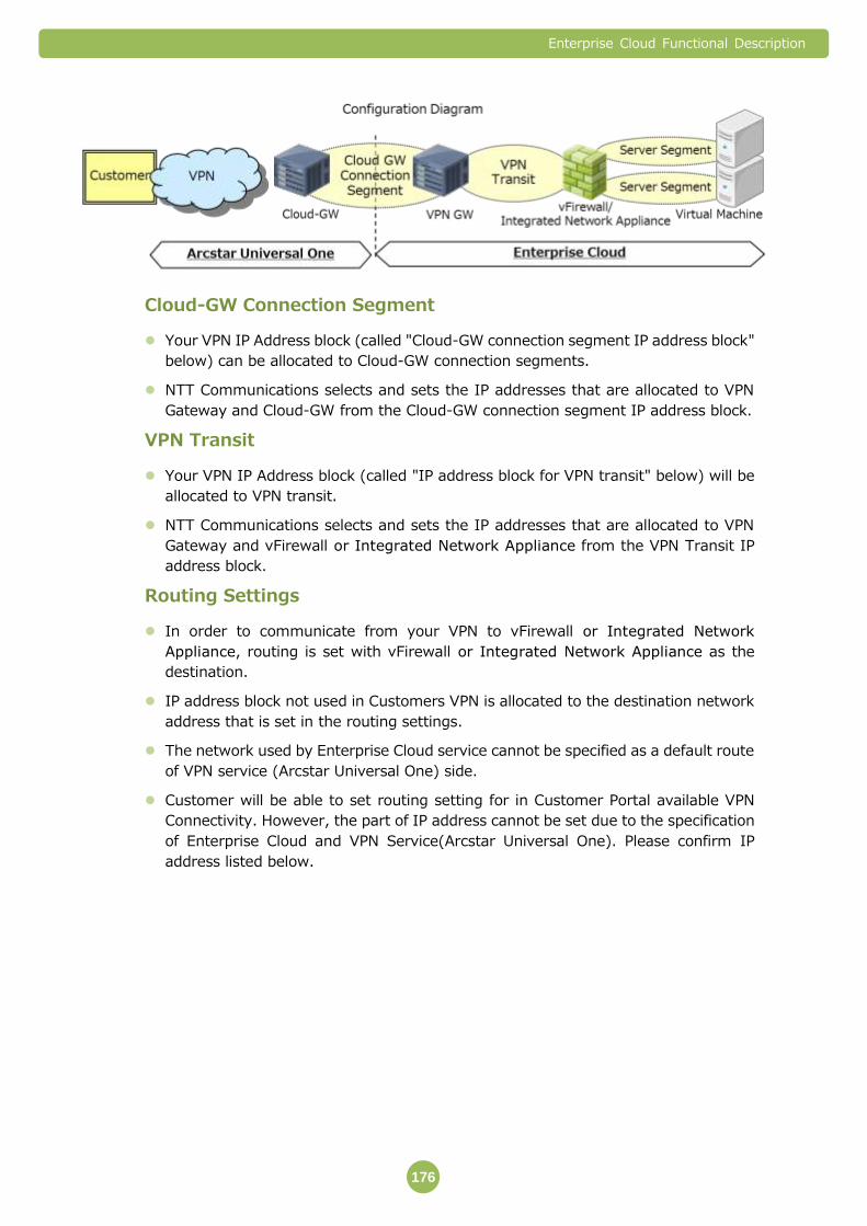
Enterprise Cloud Functional Description
176
Cloud-GW Connection Segment
Your VPN IP Address block (called "Cloud-GW connection segment IP address block"
below) can be allocated to Cloud-GW connection segments.
NTT Communications selects and sets the IP addresses that are allocated to VPN
Gateway and Cloud-GW from the Cloud-GW connection segment IP address block.
VPN Transit
Your VPN IP Address block (called "IP address block for VPN transit" below) will be
allocated to VPN transit.
NTT Communications selects and sets the IP addresses that are allocated to VPN
Gateway and vFirewall or Integrated Network Appliance from the VPN Transit IP
address block.
Routing Settings
In order to communicate from your VPN to vFirewall or Integrated Network
Appliance, routing is set with vFirewall or Integrated Network Appliance as the
destination.
IP address block not used in Customers VPN is allocated to the destination network
address that is set in the routing settings.
The network used by Enterprise Cloud service cannot be specified as a default route
of VPN service (Arcstar Universal One) side.
Customer will be able to set routing setting for in Customer Portal available VPN
Connectivity. However, the part of IP address cannot be set due to the specification
of Enterprise Cloud and VPN Service(Arcstar Universal One). Please confirm IP
address listed below.
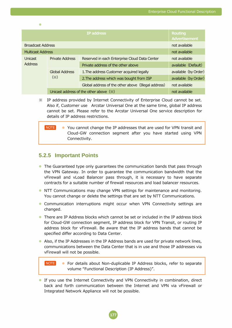
Enterprise Cloud Functional Description
177
IP address Routing
Advertisement
Broadcast Address not available
Multicast Address not available
Unicast
Address
Private Address Reserved in each Enterprise Cloud Data Center not available
Private address of the other above available(Default)
Global Address
(※)
1.The address Customer acquired legally available(by Order)
2.The address which was bought from ISP available(by Order)
Global address of the other above(Illegal address) not available
Unicast address of the other above(※) not available
※ IP address provided by Internet Connectivity of Enterprise Cloud cannot be set.
Also if, Customer use Arcstar Universal One at the same time, global IP address
cannot be set. Please refer to the Arcstar Universal One service description for
details of IP address restrictions.
You cannot change the IP addresses that are used for VPN transit and
Cloud-GW connection segment after you have started using VPN
Connectivity.
Important Points 5.2.5
The Guaranteed type only guarantees the communication bands that pass through
the VPN Gateway. In order to guarantee the communication bandwidth that the
vFirewall and vLoad Balancer pass through, it is necessary to have separate
contracts for a suitable number of firewall resources and load balancer resources.
NTT Communications may change VPN settings for maintenance and monitoring.
You cannot change or delete the settings that are set by NTT Communications.
Communication interruptions might occur when VPN Connectivity settings are
changed.
There are IP Address blocks which cannot be set or included in the IP address block
for Cloud-GW connection segment, IP address block for VPN Transit, or routing IP
address block for vFirewall. Be aware that the IP address bands that cannot be
specified differ according to Data Center.
Also, if the IP Addresses in the IP Address bands are used for private network lines,
communications between the Data Center that is in use and those IP addresses via
vFirewall will not be possible.
For details about Non-duplicable IP Address blocks, refer to separate
volume “Functional Description (IP Address)”.
If you use the Internet Connectivity and VPN Connectivity in combination, direct
back and forth communication between the Internet and VPN via vFirewall or
Integrated Network Appliance will not be possible.

Enterprise Cloud Functional Description
178
If you started using the VPN Connectivity at Yokohama No.1 Data Center on or
before November 15, 2013 and have not carried out lease construction for changing
bandwidth, you should pay attention to the following points.
To be Customer Portal available
- VPN Connectivity service termination and new order is needed.
Change bandwidth
- Lease construction is necessary for changing bandwidth. Please specify a
construction date of at least 17 business days after the date you order it. Also,
on the date of construction there might be multiple communication
interruptions that last up to several tens of minutes each.
- If you are connected to a VPN other than Arcstar Universal One Service when
the above-mentioned leased construction takes place, you will need to
transfer to Arcstar Universal One.
- Prefix Length of IP Address Blocks /29-/8 are available.
If you started using the VPN Connectivity at Yokohama No.1 Data Center after
November 15, 2013, you should pay attention to the following points.
To be Customer Portal Available
- VPN Connectivity service termination and new order is needed.
Change bandwidth in order form
- Lease construction is not necessary. 17 business days is needed to change.
Cloud-GW Connectivity segment setting is not necessary in Customer Portal
available VPN Connectivity. Moreover,1Gbps Guaranteed plan is not available.
IP address blocks listed below will be sent out to VPN service as route advertisement
regardless of customer’s setting.
- VPN transit
- Cloud-GW connection segment
When adding the Customer Portal supported VPN Connectivity, the IP address
assigned to VPN transit must be one of the unused IP in VPN Network. It cannot
overlap nor include the connected IP of VPN site(including Cloud-GW) and LAN
address.
In routing settings in Customer Portal supported VPN Connectivity, order form is
needed in order to set Global IP address for routing. Without the order form, setting
by Customer Portal will not be available. Please contact each NTT Communications
affiliate.

Enterprise Cloud Functional Description
179
5.3 Server Segment
Server segment is a service that extends Server Segments. We provide L2
segments (called "Server Segment" below) to interconnect the multiple services
that make up Enterprise Cloud.
You can connect the Virtual Machines, vLoad Balancers and Service Interconnect
Gateways over the Server Segment and also construct systems with complex
network structures.
The standard is for one Server Segment to be provided
Available Features 5.3.1
The following features are available for Server Segment.
Feature Overview
Server Segments are
provided
A feature that uses L2 segments to interconnect the
multiple services which make up Enterprise Cloud.
Server Segments Are Provided 5.3.2
The standard is for one Server Segments to be provided. You can specify Server
Segments within the ranges listed below for each Data Center.
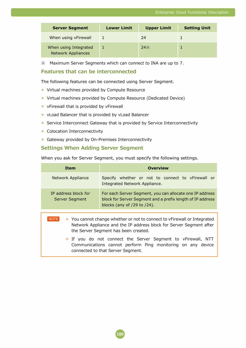
Enterprise Cloud Functional Description
180
Server Segment Lower Limit Upper Limit Setting Unit
When using vFirewall 1 24 1
When using Integrated
Network Appliances
1 24※ 1
※ Maximum Server Segments which can connect to INA are up to 7.
Features that can be interconnected
The following features can be connected using Server Segment.
Virtual machines provided by Compute Resource
Virtual machines provided by Compute Resource (Dedicated Device)
vFirewall that is provided by vFirewall
vLoad Balancer that is provided by vLoad Balancer
Service Interconnect Gateway that is provided by Service Interconnectivity
Colocation Interconnectivity
Gateway provided by On-Premises Interconnectivity
Settings When Adding Server Segment
When you ask for Server Segment, you must specify the following settings.
Item Overview
Network Appliance Specify whether or not to connect to vFirewall or
Integrated Network Appliance.
IP address block for
Server Segment
For each Server Segment, you can allocate one IP address
block for Server Segment and a prefix length of IP address
blocks (any of /29 to /24).
You cannot change whether or not to connect to vFirewall or Integrated
Network Appliance and the IP address block for Server Segment after
the Server Segment has been created.
If you do not connect the Server Segment to vFirewall, NTT
Communications cannot perform Ping monitoring on any device
connected to that Server Segment.
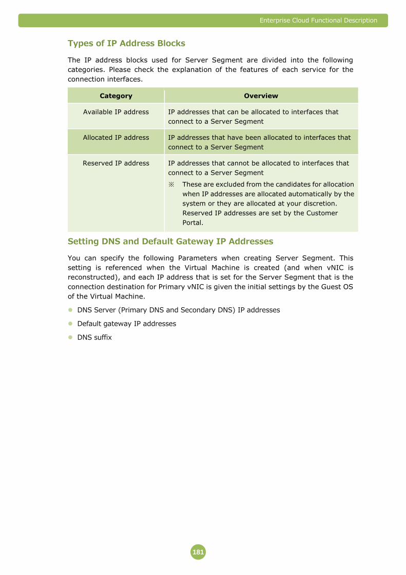
Enterprise Cloud Functional Description
181
Types of IP Address Blocks
The IP address blocks used for Server Segment are divided into the following
categories. Please check the explanation of the features of each service for the
connection interfaces.
Category Overview
Available IP address IP addresses that can be allocated to interfaces that
connect to a Server Segment
Allocated IP address IP addresses that have been allocated to interfaces that
connect to a Server Segment
Reserved IP address IP addresses that cannot be allocated to interfaces that
connect to a Server Segment
※ These are excluded from the candidates for allocation
when IP addresses are allocated automatically by the
system or they are allocated at your discretion.
Reserved IP addresses are set by the Customer
Portal.
Setting DNS and Default Gateway IP Addresses
You can specify the following Parameters when creating Server Segment. This
setting is referenced when the Virtual Machine is created (and when vNIC is
reconstructed), and each IP address that is set for the Server Segment that is the
connection destination for Primary vNIC is given the initial settings by the Guest OS
of the Virtual Machine.
DNS Server (Primary DNS and Secondary DNS) IP addresses
Default gateway IP addresses
DNS suffix

Enterprise Cloud Functional Description
182
The parameter setting for each address differs depending on whether customer
uses vFirewall or Integrated Network Appliance.
vFirewall Integrated Network Appliance
DNS Server (Primary
DNS, Secondary DNS)
IP Address
・IP addresses specified by Customer or NTTCommunications
Default gateway IP
Address
・Customer can specify the
IP address at the time
Server Segment is
created.
(Cannot be changed after
activation) If it was not
specified vFirewall
AcitveIP address is
assigned.
・When the segment is connected
to INA, ActiveIP address is
assigned. It cannot be changed.
・ When the segment is not
connected to INA, Customer can
specify the IP address. It cannot
be changed. When the IP
address is not be specified NTT
Communications will be
specified.
DNS suffix ・IP addresses specified by Customer or no value
※ The IP address that is set for Server Segments that do not connect to the
Integrated Network Appliance is "the "broadcast address" of the IP address block
for the Server Segment - 1." For example, if the IP address block is
"192.168.0.0/24," the IP address that is "the "broadcast address" of the IP
address block for the Server Segment - 1" will be "192.168.0.254."

Enterprise Cloud Functional Description
183
You can only specify the DNS and default gateway IP address at the
time Server Segment is created.
If IP addresses have not been specified, they will be allocated automatically as shown below.
Service Allocable IP Addresses
DNS Server(Primary
DNS、Secondary DNS)
IP addresses specified by NTT Communications
Default Gateway When connected to vFirewall or Integrated
Network Appliance:Active IP Address of each
Network Appliance
When not connected to vFirewall or Integrated
Network Appliance: IP address specified by NTT
Communications
Restrictions in case of default GW is specified by Customer
vFirewall: The IP address which is set as a Default Gateway cannot be assigned to the vNIC of the Virtual Machine.
INA: The IP address which is set as a Default Gateway cannot be assigned to the vNIC of the Virtual Machine and Service Interconnectivity Gateway.
※ DNS IP address auto assigned by Guest OS Customization is not available for
resolver. It is dummy IP address. Customer prepares DNS, please.
In initial Server Segment setting for Primary vNIC, if vFirewall/INA was not set as
default gateway, customer need to set static routing on Guest OS additionally(When
returning default gateway to vFirewall/INA manually in Guest OS, it's unnecessary.).
If it is not added, Ping monitoring or OS license activation and so on will no longer be
available.
For details about IP Address blocks for static routing, refer to separate
volume “Functional Description (IP Address)”.

Enterprise Cloud Functional Description
184
Even if the default gateway is set as vFirewall/INA manually in Guest OS, and the
customer manually changed the setting of the default gateway to non- EC vFW,
customer also need to set static routing listed below on Guest OS.
Picture: Image of Static Route should be added when “non EC-FW” is set as Default Gateway.

Enterprise Cloud Functional Description
185
Important Points 5.3.3
The one Server Segment that is provided as standard when you start using the Data
Center is always connected to vFirewall or Integrated Network Appliance.
Server Segment cannot be deleted as long as the template exists on Private Catalog,
when Virtual Machine which vNIC connecting the Server Segment is converted.
There are IP Addresses which cannot be specified as IP address blocks
(Non-duplicable IP Address) for Server Segments. Be aware that the IP address
bands that cannot be specified differ according to Data Center.
For details about Non-duplicable IP Address blocks, refer to separate
volume “Functional Description (IP Address)”.
Customer’s carried-in Global IP Address can be assigned to Server Segment.
However, please note that there are following restrictions.
- Please apply via Service Order Form when adding Server Segment with Customer’s
carried-in Global IP Address.
- The direct Internet transmission is not possible via vFirewall or Integrated
Network Appliance when using the Customer’s carried-in Global IP Address. NAT
setting is necessary for the Global IP Address provided by NTT Communications.
- If the registered name for IP Address under NIC organization and the
representative contractor name of Enterprise Cloud service does not match, the
carried-in IP address would be considered as illegal Global IP Address and it cannot
be supported. Also, we cannot guarantee the sustainability of the carried-in Global
IP Address.
When over 64 Virtual Machine will be made on one Server Segment relevant to the
following condition, preliminary setting by NTTCom is needed. So please request in
ticket.
- Data Centers in Japan:Server Segment which was added before January 31st
2016.
- Data Centers the others: All Server Segments are target.
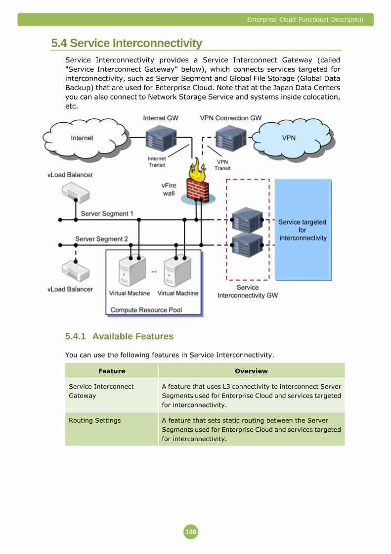
Enterprise Cloud Functional Description
186
5.4 Service Interconnectivity
Service Interconnectivity provides a Service Interconnect Gateway (called
"Service Interconnect Gateway" below), which connects services targeted for
interconnectivity, such as Server Segment and Global File Storage (Global Data
Backup) that are used for Enterprise Cloud. Note that at the Japan Data Centers
you can also connect to Network Storage Service and systems inside colocation,
etc.
Available Features 5.4.1
You can use the following features in Service Interconnectivity.
Feature Overview
Service Interconnect
Gateway
A feature that uses L3 connectivity to interconnect Server
Segments used for Enterprise Cloud and services targeted
for interconnectivity.
Routing Settings A feature that sets static routing between the Server
Segments used for Enterprise Cloud and services targeted
for interconnectivity.

Enterprise Cloud Functional Description
187
Service Interconnect Gateway 5.4.2
The Service Interconnect Gateway operates as a router. Using an L3 connection, it
connects Server Segments used for Enterprise Cloud and the networks used by
services targeted for interconnectivity.
You can specify the number of Service Interconnect Gateway that can be used in the
same Data Center within the range listed below.
Lower Limit Upper Limit Units Provided
Service Interconnect
Gateway
1 The number of
Server Segments in
use (※maximum
24 units)
1
※ With Service Interconnectivity, you can install one Service Interconnect
Gateway for each Server Segment.
You can select the IP addresses used for Service Interconnectivity from
the available IP Addresses. You can only specify them at the time the
Service Interconnect Gateway is created based on the application form.
If IP addresses have not been specified, they will be allocated automatically.
You cannot change the IP addresses that are used for Service
Interconnectivity after you have started using Service
Interconnectivity.
Global IP address cannot be assigned to the interface which connects to
the Service Interconnectivity connection service.
The Service Interconnect Gateway is configured in an active/standby
structure, so one virtual IP, one active device IP and one standby device
IP address are used.
The Service Interconnect Gateway is a Best Effort type service that
changes the transmission speed according to your system environment
and line congestion.
Routing Settings 5.4.3
You can set a maximum of 32 types of static routing for Service Interconnect
Gateway, including the default gateway.
The static routing settings are implemented based on parameter sheets
agreed upon with you and the policies of NTT Communications.
Enterprise Cloud Functional Description
188
Important Points 5.4.4
When using the same Server Segment Service Interconnectivity from a Virtual
Machine that has the default gateway set as vFirewall, the routing information of the
service targeted for the Service Interconnectivity side must be set to the Guest OS
on the Virtual Machine.
Please refer to the explanation about services targeted for interconnectivity
regarding the requirements for connection with these services.

Enterprise Cloud Functional Description
189
5.5 Colocation Interconnectivity
Colocation Interconnectivity is a service that provides a secure L2 connection
between the Server Segment that NTT Communications provides and your system
environment inside our colocation via our inter-Data Center network.
Available Features 5.5.1
You can use the following features in Colocation Interconnectivity.
Feature Overview
Layer 2 (L2) Connection A feature that connects the Server Segment NTT
Communications provides and your system environment
inside our colocation using the same Server Segment.
Layer 2 (L2) Connection 5.5.2
For one colocation connection, you can have L2 connections with Server segments (a
maximum of 24 Server Segments) using tagging VLAN.
The colocation connection is constructed of redundant physical devices
(equipment and lines).
The maximum bandwidth that can be used by one colocation is 1 Gbps.
After starting use, you can start/stop using the service by changing the communication bandwidth settings (1000Mbps/0 Mbps), and add/delete VLAN from the Customer Portal.
Connectable Colocations
The colocations that can be connected differ according to Enterprise Cloud Service
Data Center. The following are the colocations that can be connected.
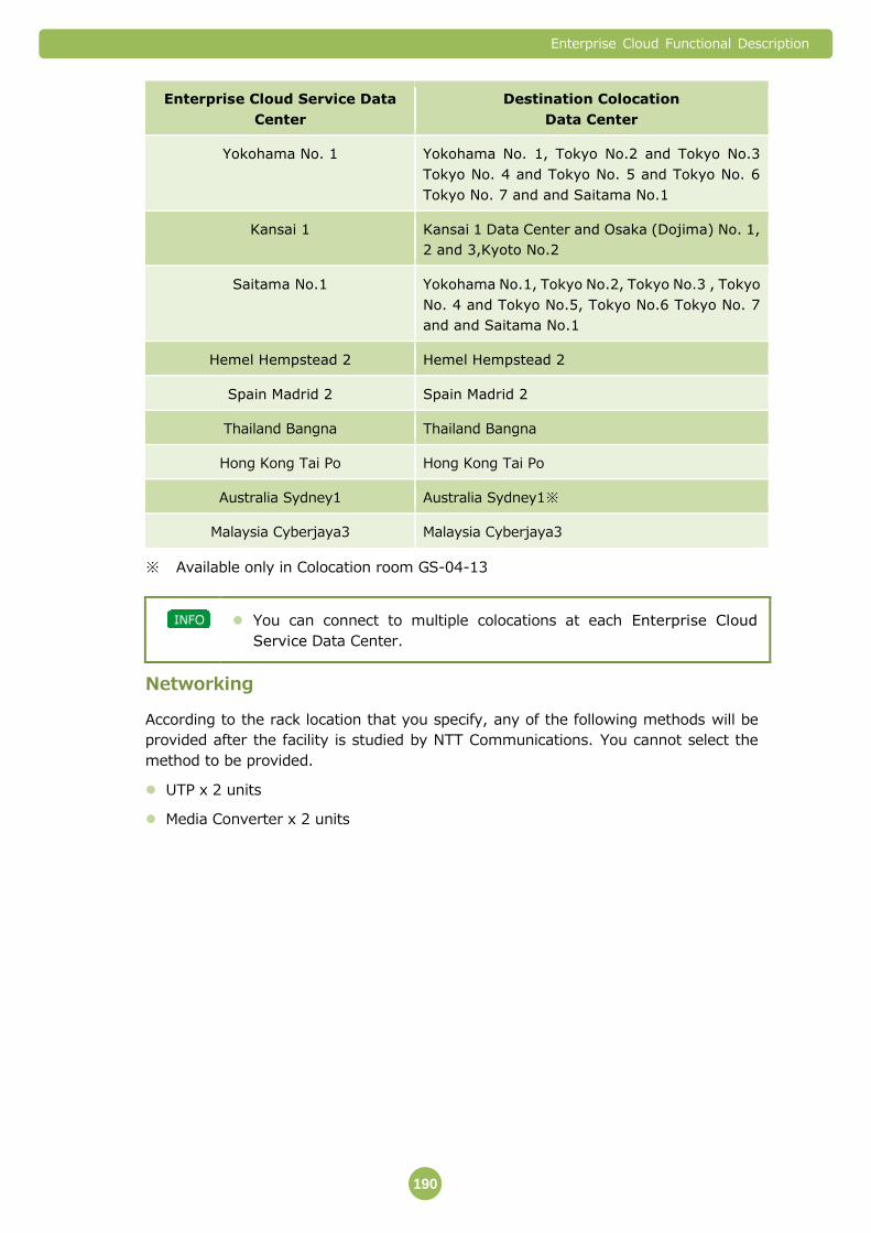
Enterprise Cloud Functional Description
190
Enterprise Cloud Service Data
Center
Destination Colocation
Data Center
Yokohama No. 1 Yokohama No. 1, Tokyo No.2 and Tokyo No.3
Tokyo No. 4 and Tokyo No. 5 and Tokyo No. 6
Tokyo No. 7 and and Saitama No.1
Kansai 1 Kansai 1 Data Center and Osaka (Dojima) No. 1,
2 and 3,Kyoto No.2
Saitama No.1 Yokohama No.1, Tokyo No.2, Tokyo No.3 , Tokyo
No. 4 and Tokyo No.5, Tokyo No.6 Tokyo No. 7
and and Saitama No.1
Hemel Hempstead 2 Hemel Hempstead 2
Spain Madrid 2 Spain Madrid 2
Thailand Bangna Thailand Bangna
Hong Kong Tai Po Hong Kong Tai Po
Australia Sydney1 Australia Sydney1※
Malaysia Cyberjaya3 Malaysia Cyberjaya3
※ Available only in Colocation room GS-04-13
You can connect to multiple colocations at each Enterprise Cloud
Service Data Center.
Networking
According to the rack location that you specify, any of the following methods will be
provided after the facility is studied by NTT Communications. You cannot select the
method to be provided.
UTP x 2 units
Media Converter x 2 units

Enterprise Cloud Functional Description
191
The media converter specifications are shown below (specifications of Japan Data
Center).
Contact us for specifications of overseas Data Center.
Country/Item JP UK,SG,HK,ES,AU TH
Height x Width x
Depth
4.24 cm × 13 cm
× 20 cm
Please contact us 4.5 cm × 9.5 cm
× 10.5 cm
Weight 0.7 kg or less
(including AC
adapter)
0.27 kg
Power supply type AC100 V AC220 V
Power consumption
(AC adapter)
10 W or less 6W
Power redundancy Single Single
Connection wiring MDI-X Auto-MDI
Linkdown forwarding Yes Yes
You must prepare a separate location and power supply for the media
converter.
In order to connect the media converter, you must have two Ethernet
cables with the same rating that are Enhanced Category 5 (Cat 5e) or
greater.
Customer L2 Switch
Please be aware of the following points regarding the Customer L2 switch settings.
For one colocation connection, a maximum of 24 VLANs can be used. Please connect
the Customer L2 switch VLAN port using tagged settings. The range of VLAN IDs
where you can specify is from 2 to 4094. The maximum number of steps of a VLAN
tag is one step.
Priority control cannot be performed according to CoS values.
Please set Interface as 1000GASE-T, the connection procedure to Auto Negotiation.
The UTP x 2 cables and the media converter x 2 units, which are the connection
points, have a redundant configuration. Please set L2 switch as active and standby
configuration to avoid frame a loop in Layer 2 and connection braking off.
Please set the Customer system so that no problems occur if part of the provided
network has a communication interruption.
The minimum frame length is 68 bytes (tag) and the maximum is 1,522 bytes (tag).
IEEE 802.3x (pause) and LLDP cannot be used with the Customer L2 switch.

Enterprise Cloud Functional Description
192
To set redundant configuration customer selected, please use the
VLAN-ID between from 2 to 4094 with tagged settings. Please confirm
beforehand whether the L2 switch prepared for this service can be
available to use tagged settings.
The checking-of-operations protocol used by Cisco [IOS 12.2(53)SE2]
is as follows.
- PVST+
- Rapid PVST+
- Flex Link (It isn't possible to use Flex Link at the Data Center where
LPT isn't supported.)
NTT Communications does not support about actual connectivity in
all IOS version.
Untagged control frame defined by Spanning Tree Protocol (IEEE
802.1d) will be discarded systematically.
L2 Broadcast, L2 Multicast and Unknown Unicast that exceed 10 Mbps
may be discarded.
Even if the communication bandwidth is set to Disabled (0 Mbps), the
control frames can communicate at approximately 100kbps and other
frames can communicate at a few kbps.

Enterprise Cloud Functional Description
193
Important Points 5.5.3
Please set active and standby redundant configuration in Customer L2 switch
interface.
Communication cutting by operation of a Customer’s redundant control becomes
the outside of SLA.
If a failure occurs on the communication path of this service, the communication
path is automatically switched to another route and communications are restored in
approximately 30 seconds.
Within the Customer system environment that is connected by colocation
interconnectivity, one MAC address can be used for one IP address.
The MAC addresses used by Enterprise Cloud are shown below. For the Customer
system, please use MAC addresses that do not duplicate the following MAC
addresses.
Note that the following MAC addresses may be changed. We apologize in
advance for this.
- MAC addresses that begin with 00-50-56 (VMWare)
- MAC addresses that begin with a2
- MAC addresses that begin with 00-0b-fc-fe-1b
- MAC addresses that begin with 00-00-0c-07-ac(HSRPv1)
- 00-00-0c-9f-f0-00~00-00-0c-9f-ff-9f (HSRPv2) (※1)
- 00-00-5e-00-01-00~00-00-5e-00-01-fb (VRRPv2) (※2)
Two or more Enterprise Cloud connection via Colocation Connectivity is not
supported. There is a possibility that the MAC address assigned to Virtual Machine
may overlap and communication trouble may happen.
Multiple Links (two or more contracts) can be increased connection bandwidth
between Enterprise Cloud and Colocation. But one Server Segment can be
connected to one link.
※5 Please use from 00-00-0c-9f-ff-a0 onward for the Customer system.
※6 Please use from 00-00-5e-00-01-fc onward for the Customer system.
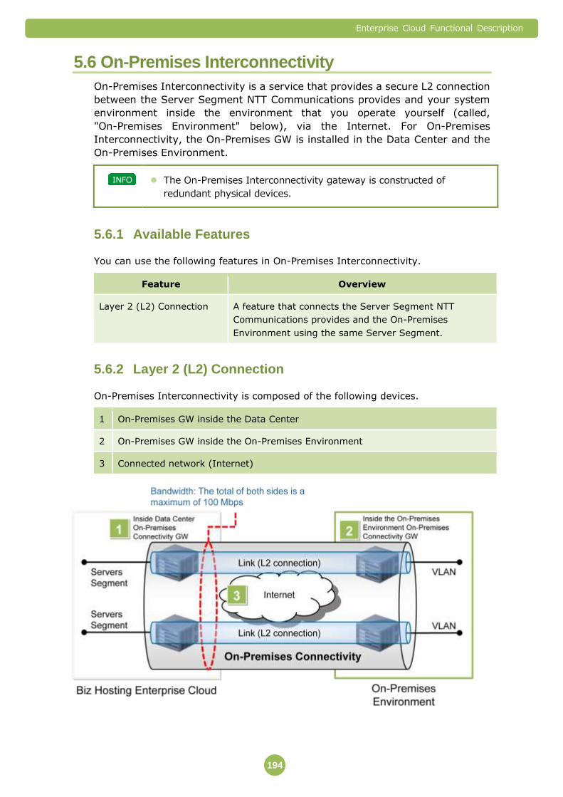
Enterprise Cloud Functional Description
194
5.6 On-Premises Interconnectivity
On-Premises Interconnectivity is a service that provides a secure L2 connection
between the Server Segment NTT Communications provides and your system
environment inside the environment that you operate yourself (called,
"On-Premises Environment" below), via the Internet. For On-Premises
Interconnectivity, the On-Premises GW is installed in the Data Center and the
On-Premises Environment.
The On-Premises Interconnectivity gateway is constructed of
redundant physical devices.
Available Features 5.6.1
You can use the following features in On-Premises Interconnectivity.
Feature Overview
Layer 2 (L2) Connection A feature that connects the Server Segment NTT
Communications provides and the On-Premises
Environment using the same Server Segment.
Layer 2 (L2) Connection 5.6.2
On-Premises Interconnectivity is composed of the following devices.
1 On-Premises GW inside the Data Center
2 On-Premises GW inside the On-Premises Environment
3 Connected network (Internet)

Enterprise Cloud Functional Description
195
Adding and Reducing L2 Connections
You can add, change and delete L2 connections between NTT Communications’s
Server Segments and On-Premises Environment, within the ranges listed below for
one On-Premises Interconnectivity.
Lower Limit Upper Limit Setting Unit
Number of L2 connections 1 24 1
You can connect to multiple On-Premises Environments at each Data
Center.
The bandwidth that can be used for one On-Premises Interconnectivity
is a maximum of 100 Mbps for the total communication going both
ways.
The connection network is provided via the Internet, so quality cannot
be guaranteed.
Use Conditions for On-Premises Interconnectivity
The following shows an example of general On-Premises Environment structure.
Here is an explanation of the required conditions for the On-Premises Environment,
for connecting between Server Segment and the On-Premises Environment.
You are responsible for the design and settings of "your own area"
within the On-Premises Environment.
On-Premises GW inside the Data Center
The connection line from the On-Premises GW inside the Data Center to the Internet
is provided by dedicated On-Premises Interconnectivity lines. An Internet
Connectivity service is not necessary. For details on Internet Connectivity, refer to "
Internet Connectivity" (⇒P.169).
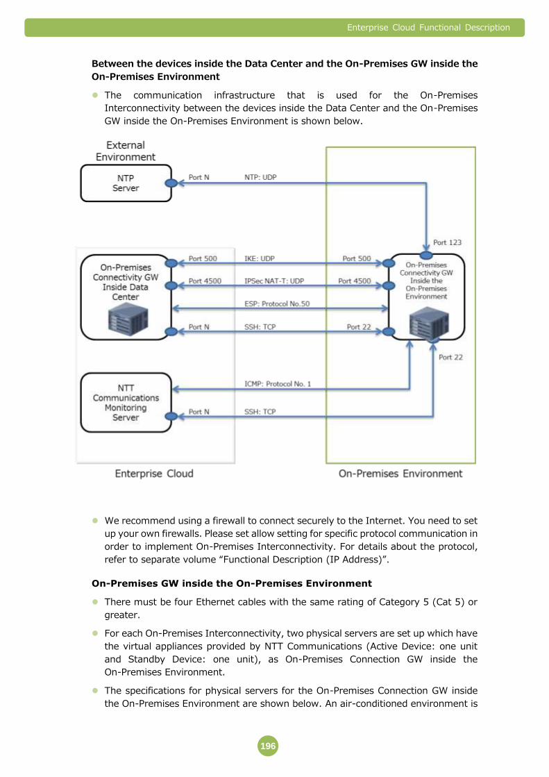
Enterprise Cloud Functional Description
196
Between the devices inside the Data Center and the On-Premises GW inside the
On-Premises Environment
The communication infrastructure that is used for the On-Premises
Interconnectivity between the devices inside the Data Center and the On-Premises
GW inside the On-Premises Environment is shown below.
We recommend using a firewall to connect securely to the Internet. You need to set
up your own firewalls. Please set allow setting for specific protocol communication in
order to implement On-Premises Interconnectivity. For details about the protocol,
refer to separate volume “Functional Description (IP Address)”.
On-Premises GW inside the On-Premises Environment
There must be four Ethernet cables with the same rating of Category 5 (Cat 5) or
greater.
For each On-Premises Interconnectivity, two physical servers are set up which have
the virtual appliances provided by NTT Communications (Active Device: one unit
and Standby Device: one unit), as On-Premises Connection GW inside the
On-Premises Environment.
The specifications for physical servers for the On-Premises Connection GW inside
the On-Premises Environment are shown below. An air-conditioned environment is
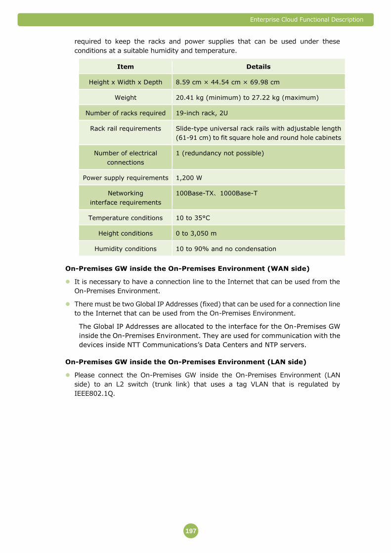
Enterprise Cloud Functional Description
197
required to keep the racks and power supplies that can be used under these
conditions at a suitable humidity and temperature.
Item Details
Height x Width x Depth 8.59 cm × 44.54 cm × 69.98 cm
Weight 20.41 kg (minimum) to 27.22 kg (maximum)
Number of racks required 19-inch rack, 2U
Rack rail requirements Slide-type universal rack rails with adjustable length
(61-91 cm) to fit square hole and round hole cabinets
Number of electrical
connections
1 (redundancy not possible)
Power supply requirements 1,200 W
Networking
interface requirements
100Base-TX、1000Base-T
Temperature conditions 10 to 35°C
Height conditions 0 to 3,050 m
Humidity conditions 10 to 90% and no condensation
On-Premises GW inside the On-Premises Environment (WAN side)
It is necessary to have a connection line to the Internet that can be used from the
On-Premises Environment.
There must be two Global IP Addresses (fixed) that can be used for a connection line
to the Internet that can be used from the On-Premises Environment.
The Global IP Addresses are allocated to the interface for the On-Premises GW
inside the On-Premises Environment. They are used for communication with the
devices inside NTT Communications’s Data Centers and NTP servers.
On-Premises GW inside the On-Premises Environment (LAN side)
Please connect the On-Premises GW inside the On-Premises Environment (LAN
side) to an L2 switch (trunk link) that uses a tag VLAN that is regulated by
IEEE802.1Q.

Enterprise Cloud Functional Description
198
The VLAN ID (Identification Number) used must fulfill the following conditions.
Usable VLAN ID Range 2 to 4,094
Number of VLAN IDs required for Server
Segment connection
1 to 24
VLAN ID (※) used in redundant
configuration
1
Number of MAC addresses for each
connected Server Segment
The number that can be used differs
depending on the prefix length.
For /26: 60
For /25: 124
For /24: 252
※ For the redundant VLAN ID, please specify a VLAN ID that is smaller than the
number of the VLAN that is used for On-Premises Interconnectivity. For
example, if the VLAN ID that is used for the L2 connection inside the
On-Premises Environment has the number 500, specify numbers from 499
and below for the redundant VLAN ID.

Enterprise Cloud Functional Description
199
Important Points 5.6.3
If failures occur, the switchover from the active device to the standby device will be
performed automatically. The time taken from when the reason for the switchover
occurs to when the switchover is completed is generally just a few seconds. Even
when the failure in the active device is solved, it does not switch over to the active
device.
Within the On-Premises Environment, the NTT Communications is only responsible
for the On-Premises GW.
On-Premises GW inside the On-Premises Environment can only be installed
(address) inside Japan. They cannot be installed outside of Japan.
If failures caused by your deliberate act occur to the physical server owned by NTT
Communications that features as the On-Premises GW inside the On-Premises
Environment, you may be held responsible for restoring it to its original condition.
You cannot use an NAT feature using a network device for the connection from
On-Premises GW inside the On-Premises Environment to the Internet.
You cannot use one Server Segment for multiple L2 connections.
You cannot connect multiple VLANs set inside a single On-Premises Environment to
the same Server Segment simultaneously.
To add and use a VLAN ID that is lower than the redundant VLAN ID in the L2 tunnel,
you need to change the redundant VLAN ID.
If different IP address blocks or subnet masks are set for the Server Segments and
VLAN inside the On-Premises Environment that connect via L2, NTT
Communications assumes no responsibility whatsoever for issues arising from those
settings.
You are responsible for IP address design in the On-Premises Environment and
Enterprise Cloud. NTT Communications assumes no responsibility for any failures
that may occur due to IP design problems.
In order to prevent adverse effects on shared equipment, NTT Communications
uses settings that partially restrict multicast and broadcast communications.
If the MAC address of the Virtual Machine of Enterprise Cloud and the MAC address
of the devices inside the On-Premises Environment overlap, the Customer might be
required to change the MAC addresses. Also, if MAC addresses adversely affect
equipment shared with other customers, we might restrict the use of On-Premises
connection without prior permission from you.
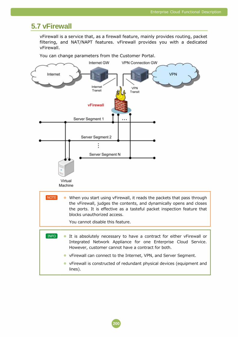
Enterprise Cloud Functional Description
200
5.7 vFirewall
vFirewall is a service that, as a firewall feature, mainly provides routing, packet
filtering, and NAT/NAPT features. vFirewall provides you with a dedicated
vFirewall.
You can change parameters from the Customer Portal.
When you start using vFirewall, it reads the packets that pass through
the vFirewall, judges the contents, and dynamically opens and closes
the ports. It is effective as a tasteful packet inspection feature that
blocks unauthorized access.
You cannot disable this feature.
It is absolutely necessary to have a contract for either vFirewall or
Integrated Network Appliance for one Enterprise Cloud Service.
However, customer cannot have a contract for both.
vFirewall can connect to the Internet, VPN, and Server Segment.
vFirewall is constructed of redundant physical devices (equipment and
lines).
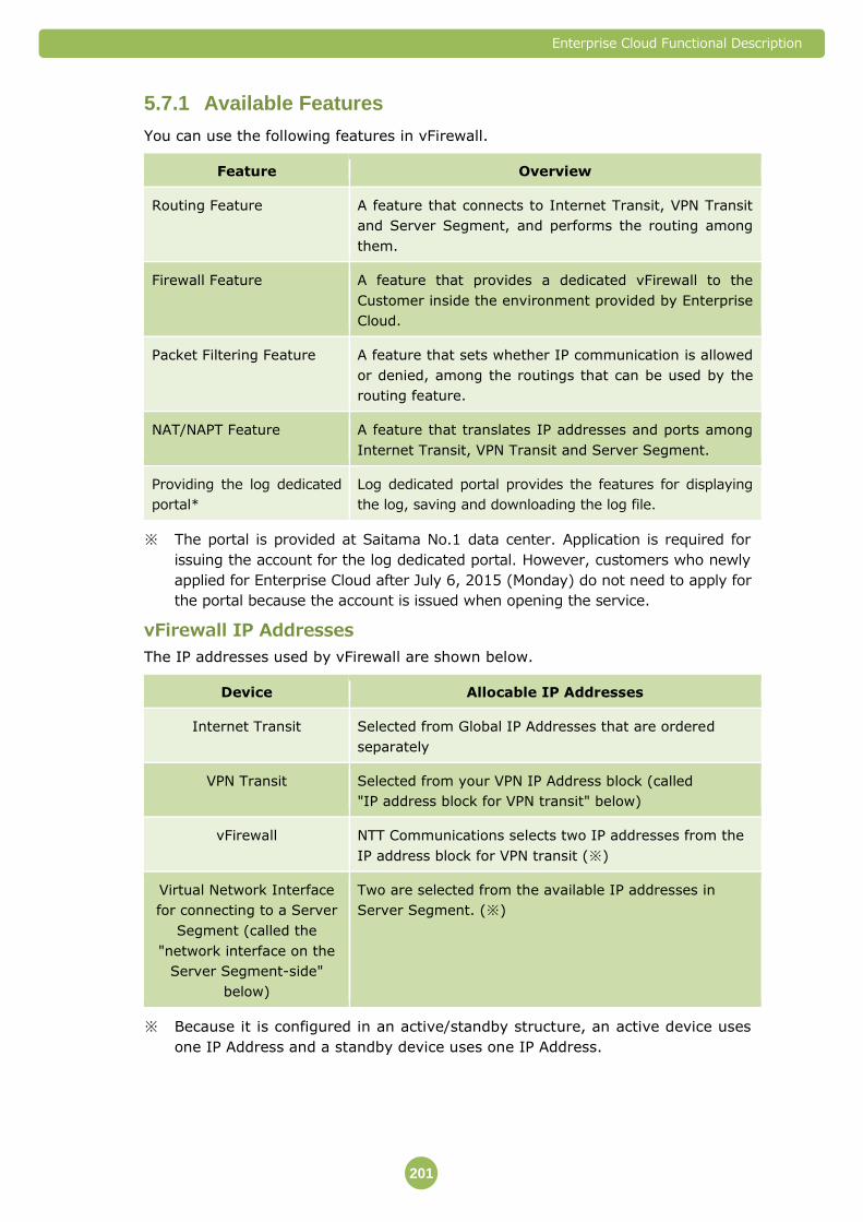
Enterprise Cloud Functional Description
201
Available Features 5.7.1
You can use the following features in vFirewall.
Feature Overview
Routing Feature A feature that connects to Internet Transit, VPN Transit
and Server Segment, and performs the routing among
them.
Firewall Feature A feature that provides a dedicated vFirewall to the
Customer inside the environment provided by Enterprise
Cloud.
Packet Filtering Feature A feature that sets whether IP communication is allowed
or denied, among the routings that can be used by the
routing feature.
NAT/NAPT Feature A feature that translates IP addresses and ports among
Internet Transit, VPN Transit and Server Segment.
Providing the log dedicated
portal*
Log dedicated portal provides the features for displaying
the log, saving and downloading the log file.
※ The portal is provided at Saitama No.1 data center. Application is required for
issuing the account for the log dedicated portal. However, customers who newly
applied for Enterprise Cloud after July 6, 2015 (Monday) do not need to apply for
the portal because the account is issued when opening the service.
vFirewall IP Addresses
The IP addresses used by vFirewall are shown below.
Device Allocable IP Addresses
Internet Transit Selected from Global IP Addresses that are ordered
separately
VPN Transit Selected from your VPN IP Address block (called
"IP address block for VPN transit" below)
vFirewall NTT Communications selects two IP addresses from the
IP address block for VPN transit (※)
Virtual Network Interface
for connecting to a Server
Segment (called the
"network interface on the
Server Segment-side"
below)
Two are selected from the available IP addresses in
Server Segment. (※)
※ Because it is configured in an active/standby structure, an active device uses
one IP Address and a standby device uses one IP Address.
Enterprise Cloud Functional Description
202
You can specify the IP address on the Server Segment-side network
interface only when the Server Segment is created based on the
application form.
If IP addresses have not been specified, they will be allocated automatically.
You cannot change the IP addresses that are allocated to the Server
Segment-side network interface.
If you do not configure Server Segment-side network interface, the
corresponding Server Segments will not be connected with vFirewall. If
you do not connect the Server Segment to vFirewall, NTT
Communications cannot perform Ping monitoring on any device
connected to that Server Segment.
Routing Feature 5.7.2
When Internet Connectivity and VPN Connectivity are in use, vFirewall will be
connected with each network and Server Segment.
This feature performs routing between each network and Server Segment.
Static Routing
You can also set static routing to the vFirewall.
For each routing setting, the routing conditions that can be set are shown below.
Network Address
Gateway
Output Interface
If you use Internet Connectivity and VPN Connectivity in combination,
direct back and forth communication between the Internet and VPN via
vFirewall will not be possible.
The routing that uses the same interface for input interface and output
interface is not possible.
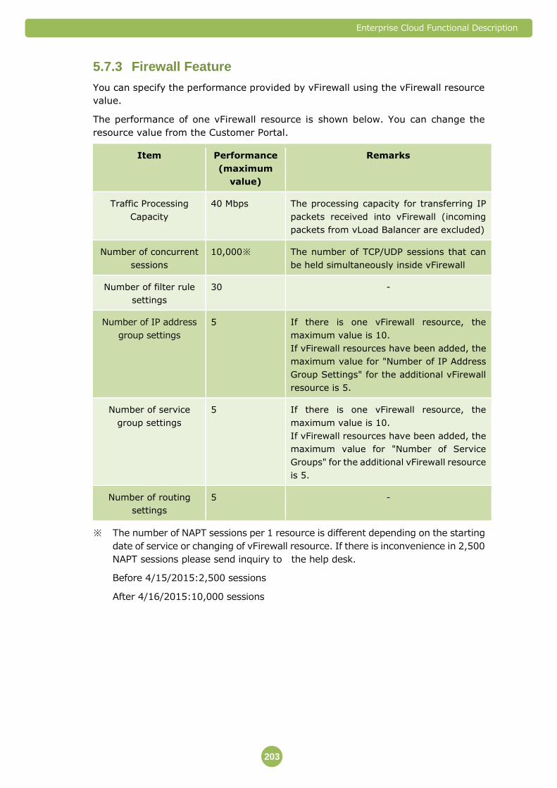
Enterprise Cloud Functional Description
203
Firewall Feature 5.7.3
You can specify the performance provided by vFirewall using the vFirewall resource
value.
The performance of one vFirewall resource is shown below. You can change the
resource value from the Customer Portal.
Item Performance
(maximum
value)
Remarks
Traffic Processing
Capacity
40 Mbps The processing capacity for transferring IP
packets received into vFirewall (incoming
packets from vLoad Balancer are excluded)
Number of concurrent
sessions
10,000※ The number of TCP/UDP sessions that can
be held simultaneously inside vFirewall
Number of filter rule
settings
30 -
Number of IP address
group settings
5 If there is one vFirewall resource, the
maximum value is 10.
If vFirewall resources have been added, the
maximum value for "Number of IP Address
Group Settings" for the additional vFirewall
resource is 5.
Number of service
group settings
5 If there is one vFirewall resource, the
maximum value is 10.
If vFirewall resources have been added, the
maximum value for "Number of Service
Groups" for the additional vFirewall resource
is 5.
Number of routing
settings
5 -
※ The number of NAPT sessions per 1 resource is different depending on the starting
date of service or changing of vFirewall resource. If there is inconvenience in 2,500
NAPT sessions please send inquiry to the help desk.
Before 4/15/2015:2,500 sessions
After 4/16/2015:10,000 sessions
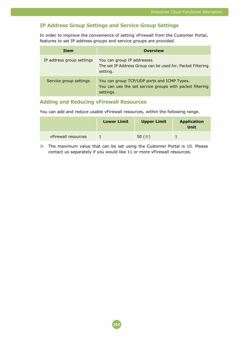
Enterprise Cloud Functional Description
204
IP Address Group Settings and Service Group Settings
In order to improve the convenience of setting vFirewall from the Customer Portal,
features to set IP address groups and service groups are provided.
Item Overview
IP address group settings You can group IP addresses.
The set IP Address Group can be used for, Packet Filtering
setting.
Service group settings You can group TCP/UDP ports and ICMP Types.
You can use the set service groups with packet filtering
settings.
Adding and Reducing vFirewall Resources
You can add and reduce usable vFirewall resources, within the following range.
Lower Limit Upper Limit Application
Unit
vFirewall resources 1 50 (※) 1
※ The maximum value that can be set using the Customer Portal is 10. Please
contact us separately if you would like 11 or more vFirewall resources.

Enterprise Cloud Functional Description
205
Packet Filtering Feature 5.7.4
A feature that specifies IP Packet filter conditions (packet filtering policy) for
vFirewall. It can allow or deny the passage of IP packets that match the filter
conditions.
You can specify the following conditions for each filter rule as IP packet filter
conditions to apply to packet filtering.
Item Overview
Interface Select any of the following as the network interface of
vFirewall that implements packet filtering.
Internet Transit
VPN Transit
Server Segment
Source IP Address Specifies a source IP address or IP address group for IP
packets.
Source Service Specifies the TCP/UDP ports, ICMP type, or service group
as the source service for IP packets.
Destination IP Address Specifies a destination IP address or IP address group for
IP packets.
Destination Service Specifies the TCP/UDP ports, ICMP type, or service group
as the destination service for IP packets.
Actions Specifies whether to allow or deny the passage of IP packets
that match the conditions set by the above-mentioned
items.
Even if you start using vFirewall, filter rules will not be set
automatically. In this case, all packets will be denied. In order to allow
communication, after starting to use vFirewall, please set filter rules at
your discretion from the Customer Portal.

Enterprise Cloud Functional Description
206
NAT/NAPT Feature 5.7.5
For vFirewall, you can set IP Address Translation and IP Address Port Translation
(called "NAT/NAPT" below) rules between Internet Transit, VPN Transit and Server
Segment.
The maximum number of NAT/NAPT setting rules that can be set for a single
vFirewall is 256.
You can translate IP addresses either 1 to 1 or 1 to N.
The IP addresses that can be set to NAT/NAPT differ depending on the
network that executes NAT/NAPT.
Network Type Allocable IP Addresses
Internet Transit Global IP Address that is used for Internet
Connectivity
VPN Transit For VPN Connectivity, an unused IP address
from the IP address block that is allocated to
VPN Transit
Server Segment Any IP address
Features that the log dedicated portal provides 5.7.6
Account for the log dedicated portal is provided. It is possible to view and download the
filter log by logging in to the portal.
Following features are provided.
Feature Item
Displaying the log
Filtering log of vFirewall is displayed on the log dedicated portal.
The latest log can be displayed by updating the browser. The log
for a maximum of 500 lines appears.
Saving the log file
One uncompressed log file including the log displayed on the
screen is saved. If the size of this file reaches 5MB, the file is
automatically compressed and saved in zip format as another file.
A maximum of 60 log files are saved.
Downloading the log
file
The saved log file can be downloaded on customer environment
from the portal.
Changing the
password
It is possible to change the account password for the log
dedicated portal.

Enterprise Cloud Functional Description
207
Important Points 5.7.7
NTT Communications may change vFirewall settings in order to perform
maintenance and monitoring. You cannot change or delete the settings that are set
by NTT Communications.
Communication interruptions might occur when you change vFirewall settings from
the Customer Portal.
Log dedicated portal
It is necessary to access to the log dedicated portal by using the Web browser via
Internet. Environment that is accessible to Internet needs to be prepared
separately.
It is possible to view and download the filter log of vFirewall. Log for other menu and
operation log of customer portal, etc. are not provided.
Browsers recommended for using the log dedicated portal are as follows.
- Mozilla Firefox 38.0
- Google Chrome 43.0.2357
Features are provided by using Syslog. Although the design sufficient for acquiring
the log is adopted, log may be damaged due to rapid increase on the shared
environment, etc. Furthermore, the log related to operation of the platform by us is
not displayed.
Inquiries regarding contents of the log and analysis of log are not supported.
Unprocessed logs of the following equipment are displayed and saved. Refer to the
information disclosed by suppliers of equipment.
- Cisco ASA 5500
SLA is not provided.
One log dedicated portal account (login ID and password) is provided. Two or more
accounts cannot be used. Furthermore, if an account is used by multiple data
centers, one account is allocated for each data center.
If you forget the password for the account, please contact our support desk.
Log is automatically compressed and saved every 5MB. Log files cannot be saved at
any time. Please note that log capacity and number of log files may increase rapidly
due to rapid increase of communications.
Logs that are compressed and saved as a log file cannot be referred on the dedicated
portal. Download and refer the saved log.
A maximum of 60 log files are stored. If more than 60 files are stored, files are
automatically deleted sequentially from the oldest file. Furthermore, arbitrary log
file cannot be deleted.
Note that the deleted log file cannot be restored.

Enterprise Cloud Functional Description
208
5.8 vLoad Balancer
vLoad Balancer is a service that provides a virtual dedicated load balancing
device over the Server Segment. You can use the load balancing feature for
communication with Virtual Machines in a Server Segment.

Enterprise Cloud Functional Description
209
Available Features 5.8.1
You can use the following features in vLoad Balancer.
Feature Overview
Load Balancing Feature A feature that balances the communication load for the
Virtual Machine on the Server Segment.
Routing Feature A feature that sets static routing to vLoad Balancer.
IP Address Delivery Feature A feature that provides a Virtual IP (called "VIP" below) for
communication between vLoad Balancer and vFirewall,
and a feature that provides a Proxy IP for communication
between vLoad Balancer and the load balancing
destination server (called "real server" below).
You can install one vLoad Balancer unit to each Server Segment.
You can change the settings of vLoad Balancer from the Customer
Portal.
Load Balancing Feature 5.8.2
vLoad Balancer Performance
You can specify the performance provided by vLoad Balancer using the vLoad
Balancer values.
The performance of one vLoad Balancer resource is shown below.
Item Performance
(maximum
value)
Remarks
Traffic Processing Capacity 20 Mbps Processing capacity for transferring IP
packets received into vLoad Balancer
Number of concurrent
sessions
20,000 Number of TCP/UDP sessions that can
be held simultaneously inside vLoad
Balancer.
※ Unlike vFirewall, when inbound and
outbound communications occur,
each one session is held.
Number of Health Check
Definitions
10 -
Number of Real Server
Settings
20 -
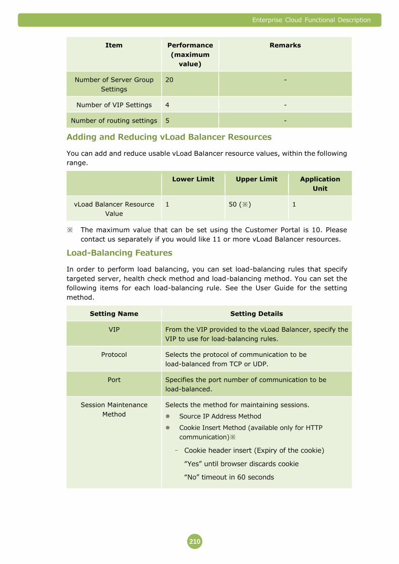
Enterprise Cloud Functional Description
210
Item Performance
(maximum
value)
Remarks
Number of Server Group
Settings
20 -
Number of VIP Settings 4 -
Number of routing settings 5 -
Adding and Reducing vLoad Balancer Resources
You can add and reduce usable vLoad Balancer resource values, within the following
range.
Lower Limit Upper Limit Application
Unit
vLoad Balancer Resource
Value
1 50 (※) 1
※ The maximum value that can be set using the Customer Portal is 10. Please
contact us separately if you would like 11 or more vLoad Balancer resources.
Load-Balancing Features
In order to perform load balancing, you can set load-balancing rules that specify
targeted server, health check method and load-balancing method. You can set the
following items for each load-balancing rule. See the User Guide for the setting
method.
Setting Name Setting Details
VIP From the VIP provided to the vLoad Balancer, specify the
VIP to use for load-balancing rules.
Protocol Selects the protocol of communication to be
load-balanced from TCP or UDP.
Port Specifies the port number of communication to be
load-balanced.
Session Maintenance
Method
Selects the method for maintaining sessions.
Source IP Address Method
Cookie Insert Method (available only for HTTP
communication)※
- Cookie header insert (Expiry of the cookie)
“Yes” until browser discards cookie
“No” timeout in 60 seconds

Enterprise Cloud Functional Description
211
Setting Name Setting Details
Server Group Specifies the server groups to which to apply these
load-balancing rules.
Selects the health check method from any one of the
following.
- TCP Port
- ICMP Ping
Selects the load-balancing method from any one of the
following.
- Round Robin (Distributes to each real server
(load balancing destination server) in order)
- Hash (Fixes the real server that is distribution
destination based on the hash value of the source
IP address)
- Least Connections (Distributes to the real server
with the least number of connections)
Backup Server Group If the health check feature detects failures in all the real
servers in the server group, a server group can be specified
to receive distribution as backup devices (standby devices).
Header Addition Feature※ Specifies whether to enable or disable the feature that
adds the x-forwarded-for header to HTTP communication.
※ HTTP header packet more than 4096bytes cannot be available.In Yokohama
No.1 or Kansai1 or Saitama No.1 Data Center, x-forwarded-for field is inserted into
only http Request header. If Customer uses vLoad Balancer in other Data Center,
x-forwarded-for field is inserted into http Request and Response header if
Header Addition feature is enabled in vLoad balancer which is added before the
maintenance during November 4 from October 27, 2015. If vLoad balancer is
added after maintenance, x-forwarded-for field is inserted into only http
Request header.
You can set the load-balancing method when you add server groups,
and you can also change them after that.
Health Check Feature
The health check feature detects real server failures. It sends pings or ICMP pings to
the TCP port of the real server at 2-second intervals. If they fail 4 times in a row it is
judged that the relevant real server is experiencing communication interruptions.
If it is determined that the real server’s communication is interrupted, the relevant
real server is excluded from the load balancing destination server, and packets are
no longer transferred. Instead, packets are sent to a different real server within the
same server group.
After it has been determined that the real server’s communication is interrupted, it
sends pings or ICMP pings to the TCP port of the real server at 30-second intervals.
If the ping succeeds twice in a row, it is determined that the communication has been
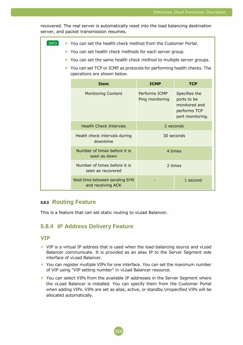
Enterprise Cloud Functional Description
212
recovered. The real server is automatically reset into the load balancing destination
server, and packet transmission resumes.
You can set the health check method from the Customer Portal.
You can set health check methods for each server group.
You can set the same health check method to multiple server groups.
You can set TCP or ICMP as protocols for performing health checks. The
operations are shown below.
Item ICMP TCP
Monitoring Content Performs ICMP
Ping monitoring
Specifies the
ports to be
monitored and
performs TCP
port monitoring.
Health Check Intervals 2 seconds
Heath check intervals during
downtime
30 seconds
Number of times before it is
seen as down
4 times
Number of times before it is
seen as recovered
2 times
Wait time between sending SYN
and receiving ACK
- 1 second
Routing Feature 5.8.3
This is a feature that can set static routing to vLoad Balancer.
IP Address Delivery Feature 5.8.4
VIP
VIP is a virtual IP address that is used when the load-balancing source and vLoad
Balancer communicate. It is provided as an alias IP to the Server Segment side
interface of vLoad Balancer.
You can register multiple VIPs for one interface. You can set the maximum number
of VIP using "VIP setting number" in vLoad Balancer resource.
You can select VIPs from the available IP addresses in the Server Segment where
the vLoad Balancer is installed. You can specify them from the Customer Portal
when adding VIPs. VIPs are set as alias, active, or standby.Unspecified VIPs will be
allocated automatically.

Enterprise Cloud Functional Description
213
Proxy IP
Proxy IP is a virtual IP address that is used when the real server and vLoad Balancer
communicate. It is provided as an alias IP to the Server Segment side interface of
vLoad Balancer.
You can register multiple Proxy IPs for one interface.
You can select Proxy IPs from the available IP addresses in the Server Segment
where the vLoad Balancer is installed. You can specify them from the Customer
Portal when adding Proxy IPs. Proxy IPs are set as alias, active, or
standby.Unspecified Proxy IPs will be allocated automatically.
The number of Proxy IPs used differs according to the vLoad Balancer resource
value that is used. When you change the vLoad Balancer resource value, Proxy IP
will automatically be added or reduced by the system.
vLoad Balancer Resource Value Number of Proxy IP Used
1 to 2 1
3 to 4 2
5 to 6 3
7 to 8 4
9 to 10 5
11 or more One for every two additional vLoad
Balancer resource values
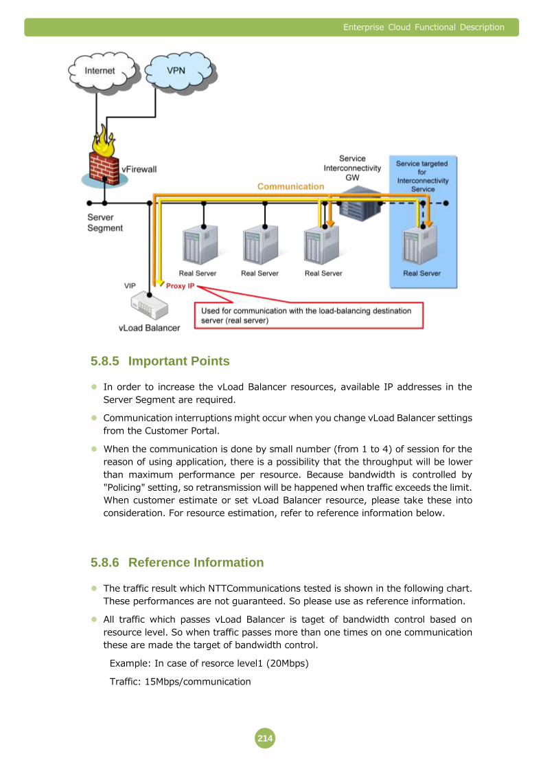
Enterprise Cloud Functional Description
214
Important Points 5.8.5
In order to increase the vLoad Balancer resources, available IP addresses in the
Server Segment are required.
Communication interruptions might occur when you change vLoad Balancer settings
from the Customer Portal.
When the communication is done by small number (from 1 to 4) of session for the
reason of using application, there is a possibility that the throughput will be lower
than maximum performance per resource. Because bandwidth is controlled by
"Policing" setting, so retransmission will be happened when traffic exceeds the limit.
When customer estimate or set vLoad Balancer resource, please take these into
consideration. For resource estimation, refer to reference information below.
Reference Information 5.8.6
The traffic result which NTTCommunications tested is shown in the following chart.
These performances are not guaranteed. So please use as reference information.
All traffic which passes vLoad Balancer is taget of bandwidth control based on
resource level. So when traffic passes more than one times on one communication
these are made the target of bandwidth control.
Example: In case of resorce level1 (20Mbps)
Traffic: 15Mbps/communication

Enterprise Cloud Functional Description
215
passes twice: 15Mbps x 2 =30Mbps
2 resorces will be needed actually.
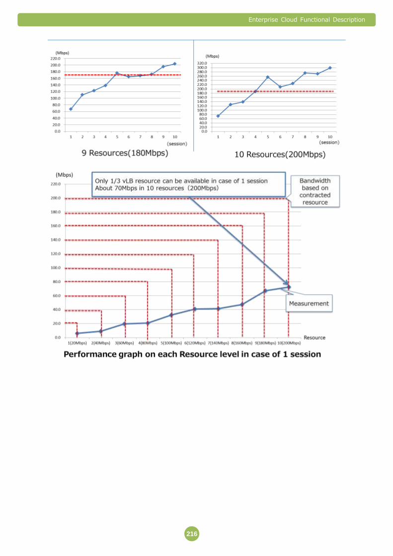
Enterprise Cloud Functional Description
216

Enterprise Cloud Functional Description
217
5.9 Integrated Network Appliance
Integrated Network Appliance service is the service where the virtual network
devices equipped with the firewall function, NAT/NAPT function, routing function,
load balancing function and IPsec termination function are provided. With the
Integrated Network Appliance service, one virtual network device dedicated for
customers (called “Integrated Network Appliance” below is provided. Various
parameters can be changed from Customer Port.
When starting to use the Integrated Network Appliance service, the
stateful packet inspection function used for blocking illegal access by
reading data of packets that pass through the Integrated Network
Appliance and opening/closing ports according to its contents is
enabled. This function cannot be disabled.
Either the Integrated Network Appliance or vFirewall needs to be
contracted for one Data Center in one Enterprise Cloud service contract.
These services cannot be used simultaneously or multiple services
cannot be used.

Enterprise Cloud Functional Description
218
Available Features 5.9.1
Connection to each network
The Integrated Network Appliance can connect to the following networks.
Destination Network Connection Conditions
Internet Transit If the Internet Connectivity service is selected, connection to
the Internet transit is always established.
VPN Transit If the VPN Connectivity service is selected, connection to the
VPN transit is always established.
Server Segment If a Server Segment is added, connection to the Server
Segment is provided. However, if “Do not connect to the
Integrated Network Appliance.” is selected when adding a
Server Segment, connection to the Server Segment is not
provided.
Interfaces of the Integrated Network Appliance
Interfaces and allocable IP addresses that are provided by the Integrated Network
Appliance are shown below.
Interface Allocatable IP Addresses
Virtual Network Interface for connecting to
Internet Transit (called the "network
interface on the Internet Transit-side"
below)
NTT Communications selects IP addresses
from the block for Global IP Addresses that
are ordered separately
Virtual Network Interface for connecting to
VPN Transit (called the "network interface on
the VPN Transit-side" below)
NTT Communications selects IP addresses
from the block for IP addresses of
customer’s VPN (called the “IP address
block for VPN Transit” below).
Virtual Network Interface for connecting to a
Server Segment (called the "network
interface on the Server Segment-side"
below)
Customers can select the Virtual Network
Interface from the available IP addresses in
Server Segment (You can specify the IP
address on the Server Segment-side
network interface only when the Server
Segment is created based on the
application form. If IP addresses have not
been specified, they will be allocated
automatically).

Enterprise Cloud Functional Description
219
IP addresses allocated to each interface of the Integrated Network
Appliance cannot be changed after allocating them.
Main Features of the Integrated Network Appliance
Features and rules that can be set for the Integrated Network Appliance are shown
below.
Features Name of Available Rules Details
Firewall feature Firewall rule This is the feature used for setting to
allow/deny communications that pass
through the Integrated Network
Appliance.
NAT/NAPT
feature
SNAT rule
DNAT rule
This is the feature used for converting the
IP address and ports for communications
that pass through among Internet Transit,
VPN Transit and Server Segment.
Routing feature Static routing This is the function used for providing the
routing for communications that are made
among Internet Transit, VPN Transit and
Server Segment.
Load balancing
feature
Load balancing rule This is the function used for balancing load
of communications from Internet Transit
and VPN Transit.
IPsec
termination
feature
IPsec termination rule This is the function used for terminating
IPsec communications.
Plans of the Integrated Network Appliance
You can choose from the following four Integrated Network Appliance plans. Available
performance and configurations vary depending on the plan that you order.
Plans Performance Configurations
Compact For customers who do not use the load balancing
feature and IPsec termination feature.
Single
configuration
Compact
(Redundant)
For customers who do not use the load balancing
feature and IPsec termination feature.
Redundant
configuration

Enterprise Cloud Functional Description
220
Plans Performance Configurations
Large For customers who use the load balancing feature
and IPsec termination feature. Single
configuration
Large
(Redundant)
For customers who use the load balancing feature
and IPsec termination feature. Redundant
configuration
The Integrated Network Appliance plan can be specified at the time of
submitting the application form. After the network is opened, the plan
cannot be changed from Compact to Large or vice versa. (It is possible
to change the plan from single configuration to redundant configuration
or vice versa.)
If the redundant configuration plan is selected, the hot standby
configuration is provided and the plan is switched in approximately 30
seconds. Even if the single configuration plan is selected, the redundant
configuration is adopted for basic equipment, equipment restart with
the basic equipment for backup in case of failure and the configuration
is switched approximately 5 to 10 minutes.
All functions are available with Compact plan. However, Large plan is
recommended when using the Load Balancing function and IP sec
termination function due to the plunge in performance.
Firewall Feature 5.9.2
With this feature, the firewall rules for allowing or denying specific IP packets of
communications that pass through the Integrated Network Appliance can be
configured.
The following conditions can be specified for each firewall rule as the condition for IP
packet to which the firewall rule is applied.
Item Details
Firewall Rule Customer can configure arbitrary rule names.
Source IP Address Specifies a source IP address for IP packets.

Enterprise Cloud Functional Description
221
Item Details
Source Service Specifies the source service for IP packets with the port
number when setting TCP/UDP ports for protocol. If ICMP is
specified for protocol, ICMP Type cannot be specified.
Destination IP Address Specifies a destination IP address for IP packets.
Destination Service Specifies the destination service for IP packets with the port
number when setting TCP/UDP ports for protocol. If ICMP is
specified for protocol, ICMP Type cannot be specified.
Protocol Specifies the protocol used for IP packets (TCP, UDP or
ICMP).
Actions Specifies whether to allow or deny the passage of IP
packets that match the conditions set by the
above-mentioned items.
Enable Enables/ disables this rule.
The firewall feature is set to deny all communications at the time of
opening. Settings for enabling specific communications are required to
allow communications.
Priority of firewall rules can be set by changing the display order on the
Customer Portal. Higher display order on the Customer Portal has
higher priority level.
NAT/NAPT Feature 5.9.3
You can set IP Address Translation and IP Address Port Translation (called
"SNAT/DNAT" below) rules for communications that pass through the Integrated
Network Appliance.
There are 2 types of NAT/NAPT rules for the Integrated Network Appliance.
NAT/NAPT for converting the source IP (called “SNAT” rule below)
NAT/NAPT for converting the destination IP (called “DNAT” rule below)

Enterprise Cloud Functional Description
222
SNAT Feature
The following items can be set for one SNAT rule.
Item Details
Targeted network Selects the destination network for communications to
which the SNAT rule is applied from Internet Transit, VPN
Transit and Server Segments that are connected to the
Integrated Network Appliance.
Source IP address before
conversion
Specifies the IP address that is not converted according to
this rule.
Source IP address after
conversion
Specifies the IP address that is converted according to this
rule.
Enable Enables or disables this rule.
DNAT Feature
The following items can be set for one DNAT rule.
Item Details
Targeted network Selects the destination network for communications to
which the DNAT rule is applied from Internet Transit, VPN
Transit and Server Segments that are connected to the
Integrated Network Appliance.
Source IP address before
conversion
Specifies the IP address that is not converted by this rule.
Destination port number
before conversion/ ICMP
Type
If TCP or UDP is specified for protocol, specify the port
number that is not converted according to this rule. If ICMP
is specified for protocol, ICMP Type needs to be specified.
Source IP address after
conversion
Specifies the IP address that is converted according to this
rule.
Destination port number
after conversion/ ICMP Type
If TCP or UDP is specified for protocol, specify the port
number that is not converted according to this rule. If ICMP
is specified for protocol, ICMP Type needs to be specified.
Protocol Specifies the protocol (TCP/ UDP/ ICMP) for
communications to which this rule is applied.
Enable Enables or disables this rule.
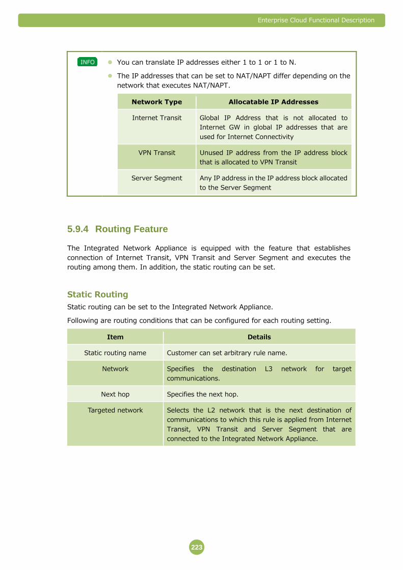
Enterprise Cloud Functional Description
223
You can translate IP addresses either 1 to 1 or 1 to N.
The IP addresses that can be set to NAT/NAPT differ depending on the
network that executes NAT/NAPT.
Network Type Allocatable IP Addresses
Internet Transit Global IP Address that is not allocated to
Internet GW in global IP addresses that are
used for Internet Connectivity
VPN Transit Unused IP address from the IP address block
that is allocated to VPN Transit
Server Segment Any IP address in the IP address block allocated
to the Server Segment
Routing Feature 5.9.4
The Integrated Network Appliance is equipped with the feature that establishes
connection of Internet Transit, VPN Transit and Server Segment and executes the
routing among them. In addition, the static routing can be set.
Static Routing
Static routing can be set to the Integrated Network Appliance.
Following are routing conditions that can be configured for each routing setting.
Item Details
Static routing name Customer can set arbitrary rule name.
Network Specifies the destination L3 network for target
communications.
Next hop Specifies the next hop.
Targeted network Selects the L2 network that is the next destination of
communications to which this rule is applied from Internet
Transit, VPN Transit and Server Segment that are
connected to the Integrated Network Appliance.

Enterprise Cloud Functional Description
224
If Internet Connectivity and VPN Connectivity are used simultaneously,
communications that directly relay back between Internet and VPN. If
NTT Communications detect the settings that execute such
communications, we may delete settings or restrict communications
without advanced notice.
The routing in which the same interface is used for the input interface
and output interface cannot be set.
Default Route
Default route of the Integrated Network Appliance can be set. Following are items that
can be set for the default route.
Item Conditions
Internet Transit When using the Internet Connectivity, Internet Transit can
be selected for the default route.
VPN Transit When using the VPN Connectivity, VPN Transit can be
selected for the default route.
Load Balancing Feature 5.9.5
You can set load balancing rules that realize distribution of communication load by
distributing communications that are terminated with the specific IP address
allocated to the Integrated Network Appliance.
You can set the following items for each load balancing rule.
Item Details
Load balancing rule name Customer can set arbitrary rule name.
Explanation Customer can arbitrarily input the explanation of this rule.
IP address This is the IP address disclosed to client.
This rule is applied to communications in which this IP
address is set for the destination IP address.
Pool Specified the destination server pool in this rule (server pool
is described later).
Protocol Specifies the protocol to which this rule is applied.
Session Maintenance
Method
Selects the method for maintaining sessions according to
this rule.
Enable Enables or disables this rule.

Enterprise Cloud Functional Description
225
Server Pool of Load Balancing
Multiple servers to which load are distributed according to the load balancing rules
can be registered as server pool. You can set the following items for each server
pool.
Item Details
Server pool name Customer can set arbitrary pool name.
Explanation Customer can arbitrarily input the explanation of this server
pool.
Member Registers one server or multiple servers in this server pool.
Protocol Specifies the protocol of communication to be distributed
and transmitted to each server.
Port Specifies the port number of communication to be
distributed and transmitted to each server.
Protocol for monitoring Selects the protocol for executing the health check for
servers registered in the server pool.
Load balancing method Selects the load balancing method when load is distributed
to this server pool.
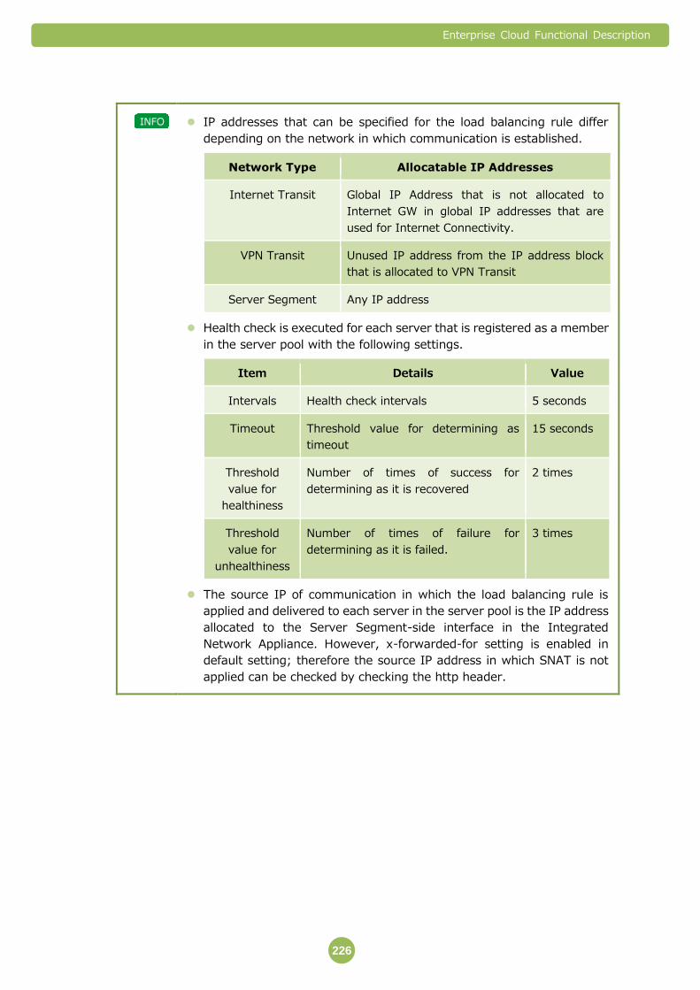
Enterprise Cloud Functional Description
226
IP addresses that can be specified for the load balancing rule differ
depending on the network in which communication is established.
Network Type Allocatable IP Addresses
Internet Transit Global IP Address that is not allocated to
Internet GW in global IP addresses that are
used for Internet Connectivity.
VPN Transit Unused IP address from the IP address block
that is allocated to VPN Transit
Server Segment Any IP address
Health check is executed for each server that is registered as a member
in the server pool with the following settings.
Item Details Value
Intervals Health check intervals 5 seconds
Timeout Threshold value for determining as
timeout
15 seconds
Threshold
value for
healthiness
Number of times of success for
determining as it is recovered
2 times
Threshold
value for
unhealthiness
Number of times of failure for
determining as it is failed.
3 times
The source IP of communication in which the load balancing rule is
applied and delivered to each server in the server pool is the IP address
allocated to the Server Segment-side interface in the Integrated
Network Appliance. However, x-forwarded-for setting is enabled in
default setting; therefore the source IP address in which SNAT is not
applied can be checked by checking the http header.
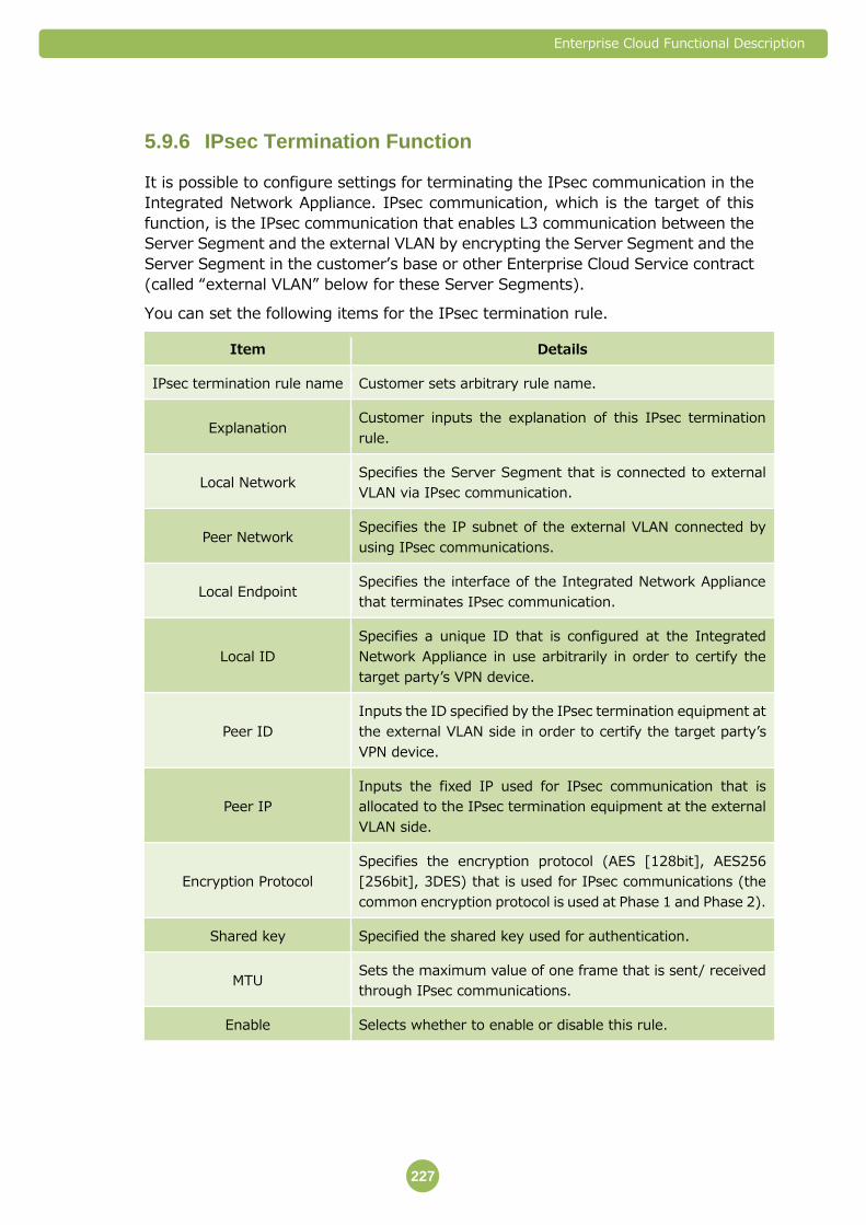
Enterprise Cloud Functional Description
227
IPsec Termination Function 5.9.6
It is possible to configure settings for terminating the IPsec communication in the
Integrated Network Appliance. IPsec communication, which is the target of this
function, is the IPsec communication that enables L3 communication between the
Server Segment and the external VLAN by encrypting the Server Segment and the
Server Segment in the customer’s base or other Enterprise Cloud Service contract
(called “external VLAN” below for these Server Segments).
You can set the following items for the IPsec termination rule.
Item Details
IPsec termination rule name Customer sets arbitrary rule name.
Explanation Customer inputs the explanation of this IPsec termination
rule.
Local Network Specifies the Server Segment that is connected to external
VLAN via IPsec communication.
Peer Network Specifies the IP subnet of the external VLAN connected by
using IPsec communications.
Local Endpoint Specifies the interface of the Integrated Network Appliance
that terminates IPsec communication.
Local ID
Specifies a unique ID that is configured at the Integrated
Network Appliance in use arbitrarily in order to certify the
target party’s VPN device.
Peer ID
Inputs the ID specified by the IPsec termination equipment at
the external VLAN side in order to certify the target party’s
VPN device.
Peer IP
Inputs the fixed IP used for IPsec communication that is
allocated to the IPsec termination equipment at the external
VLAN side.
Encryption Protocol
Specifies the encryption protocol (AES [128bit], AES256
[256bit], 3DES) that is used for IPsec communications (the
common encryption protocol is used at Phase 1 and Phase 2).
Shared key Specified the shared key used for authentication.
MTU Sets the maximum value of one frame that is sent/ received
through IPsec communications.
Enable Selects whether to enable or disable this rule.
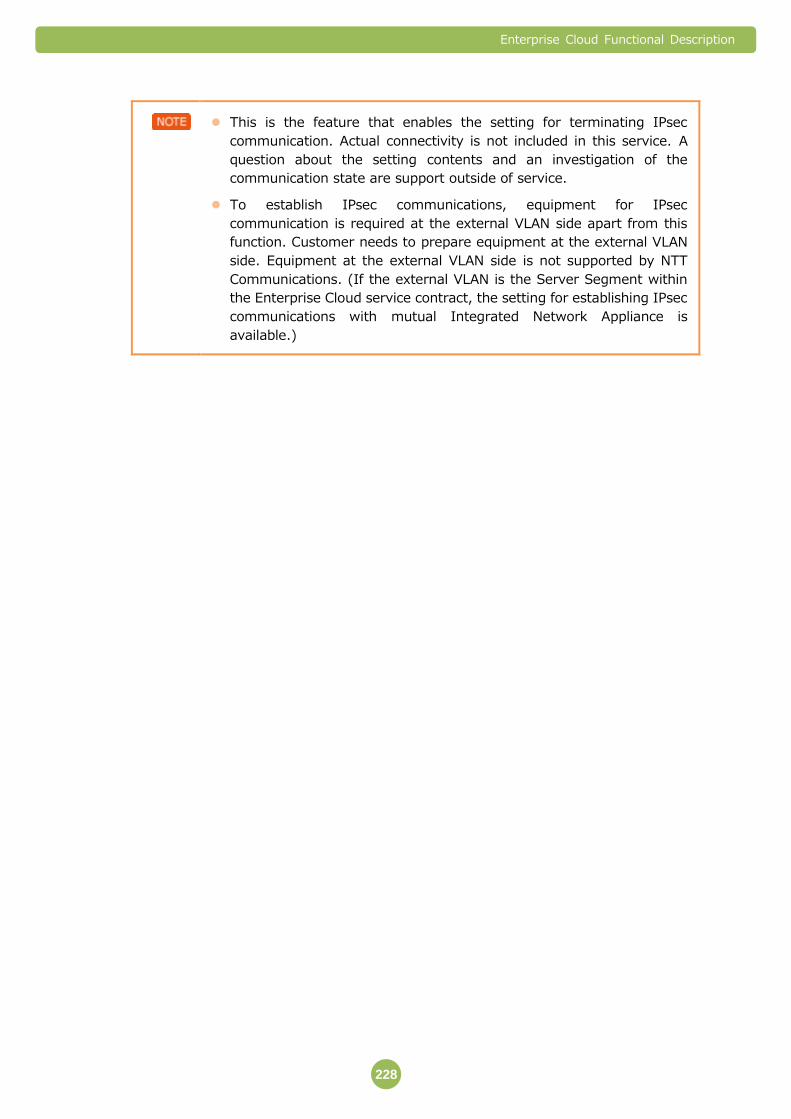
Enterprise Cloud Functional Description
228
This is the feature that enables the setting for terminating IPsec
communication. Actual connectivity is not included in this service. A
question about the setting contents and an investigation of the
communication state are support outside of service.
To establish IPsec communications, equipment for IPsec
communication is required at the external VLAN side apart from this
function. Customer needs to prepare equipment at the external VLAN
side. Equipment at the external VLAN side is not supported by NTT
Communications. (If the external VLAN is the Server Segment within
the Enterprise Cloud service contract, the setting for establishing IPsec
communications with mutual Integrated Network Appliance is
available.)
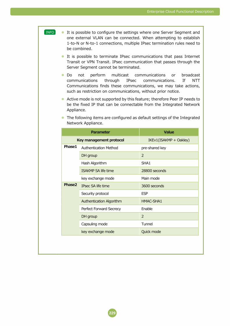
Enterprise Cloud Functional Description
229
It is possible to configure the settings where one Server Segment and
one external VLAN can be connected. When attempting to establish
1-to-N or N-to-1 connections, multiple IPsec termination rules need to
be combined.
It is possible to terminate IPsec communications that pass Internet
Transit or VPN Transit. IPsec communication that passes through the
Server Segment cannot be terminated.
Do not perform multicast communications or broadcast
communications through IPsec communications. If NTT
Communications finds these communications, we may take actions,
such as restriction on communications, without prior notice.
Active mode is not supported by this feature; therefore Peer IP needs to
be the fixed IP that can be connectable from the Integrated Network
Appliance.
The following items are configured as default settings of the Integrated
Network Appliance.
Parameter Value
Key management protocol IKEv1(ISAKMP + Oakley)
Phase1 Authentication Method pre-shared key
DH group 2
Hash Algorithm SHA1
ISAKMP SA life time 28800 seconds
key exchange mode Main mode
Phase2 IPsec SA life time 3600 seconds
Security protocol ESP
Authentication Algorithm HMAC-SHA1
Perfect Forward Secrecy Enable
DH group 2
Capsuling mode Tunnel
key exchange mode Quick mode

Enterprise Cloud Functional Description
230
Important Points 5.9.7
Rules Set by NTT Communications (Global Rule)
Multiple rules (called “Global Rule” below) are configured for the Integrated Network
Appliance in default setting to allow NTT Communications to perform monitoring,
maintenance and operation and provide various services.
Customer can refer the Global Rule. However, please note that we may not be able
to answer questions regarding specific purpose and details of the Global Rule.
Customer cannot edit or delete the Global Rule.
The Global Rule is set as the rule having the higher priority than various rules set
by customer.
Please note that the Global Rule may be added, changed or deleted by us without
prior notice.
When monitoring the virtual server starts, SNAT rule and DNAT rule are
added to the virtual server to be monitored for each virtual server to be
monitored.
Number of Configurable Rules
For the Integrated Network Appliance, the following number of rules can be set
regardless of the plan.
Feature Maximum number of rules that can be set
Firewall rule Approximately 100 rules(including Global Rules)
SNAT rule
DNAT rule
Approximately 100 rules (including Global Rules and SNAT
rule and DNAT rule)
Static routing Maximum 64 rules
Load balancing rule Approximately 3 rules
IPsec termination rules Approximately 50 rules
Performance is likely to be degraded when the number of rules set
increases.
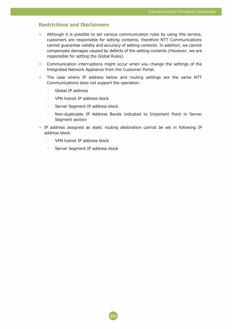
Enterprise Cloud Functional Description
231
Restrictions and Disclaimers
Although it is possible to set various communication rules by using this service,
customers are responsible for setting contents; therefore NTT Communications
cannot guarantee validity and accuracy of setting contents. In addition, we cannot
compensate damages caused by defects of the setting contents (However, we are
responsible for setting the Global Rules).
Communication interruptions might occur when you change the settings of the
Integrated Network Appliance from the Customer Portal.
The case where IP address below and routing settings are the same NTT
Communications does not support the operation.
- Global IP address
- VPN transit IP address block
- Server Segment IP address block
- Non-duplicable IP Address Bands indicated to Important Point in Server
Segment section
IP address assigned as static routing destination cannot be set in following IP
address block.
- VPN transit IP address block
- Server Segment IP address block
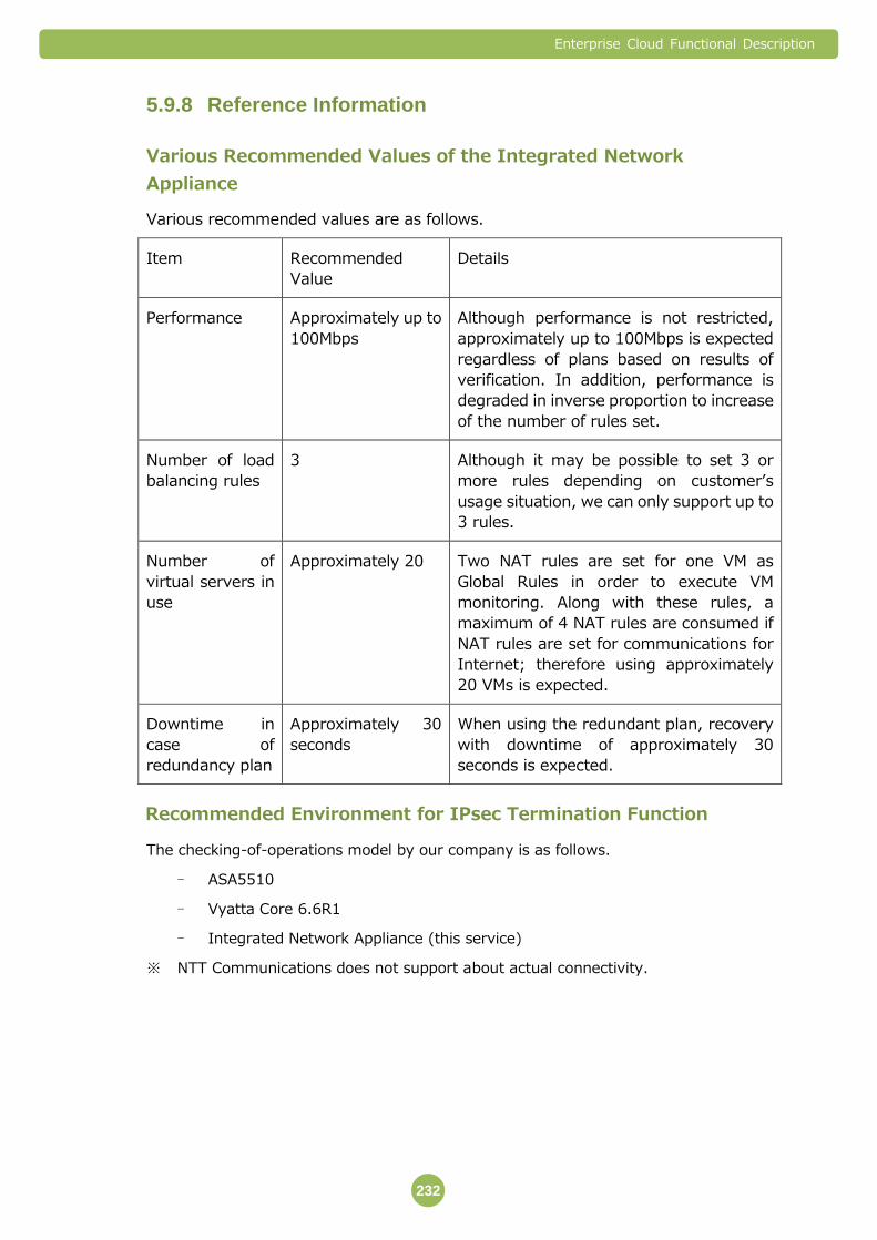
Enterprise Cloud Functional Description
232
Reference Information 5.9.8
Various Recommended Values of the Integrated Network
Appliance
Various recommended values are as follows.
Item Recommended
Value
Details
Performance Approximately up to
100Mbps
Although performance is not restricted,
approximately up to 100Mbps is expected
regardless of plans based on results of
verification. In addition, performance is
degraded in inverse proportion to increase
of the number of rules set.
Number of load
balancing rules
3 Although it may be possible to set 3 or
more rules depending on customer’s
usage situation, we can only support up to
3 rules.
Number of
virtual servers in
use
Approximately 20 Two NAT rules are set for one VM as
Global Rules in order to execute VM
monitoring. Along with these rules, a
maximum of 4 NAT rules are consumed if
NAT rules are set for communications for
Internet; therefore using approximately
20 VMs is expected.
Downtime in
case of
redundancy plan
Approximately 30
seconds
When using the redundant plan, recovery
with downtime of approximately 30
seconds is expected.
Recommended Environment for IPsec Termination Function
The checking-of-operations model by our company is as follows.
- ASA5510
- Vyatta Core 6.6R1
- Integrated Network Appliance (this service)
※ NTT Communications does not support about actual connectivity.
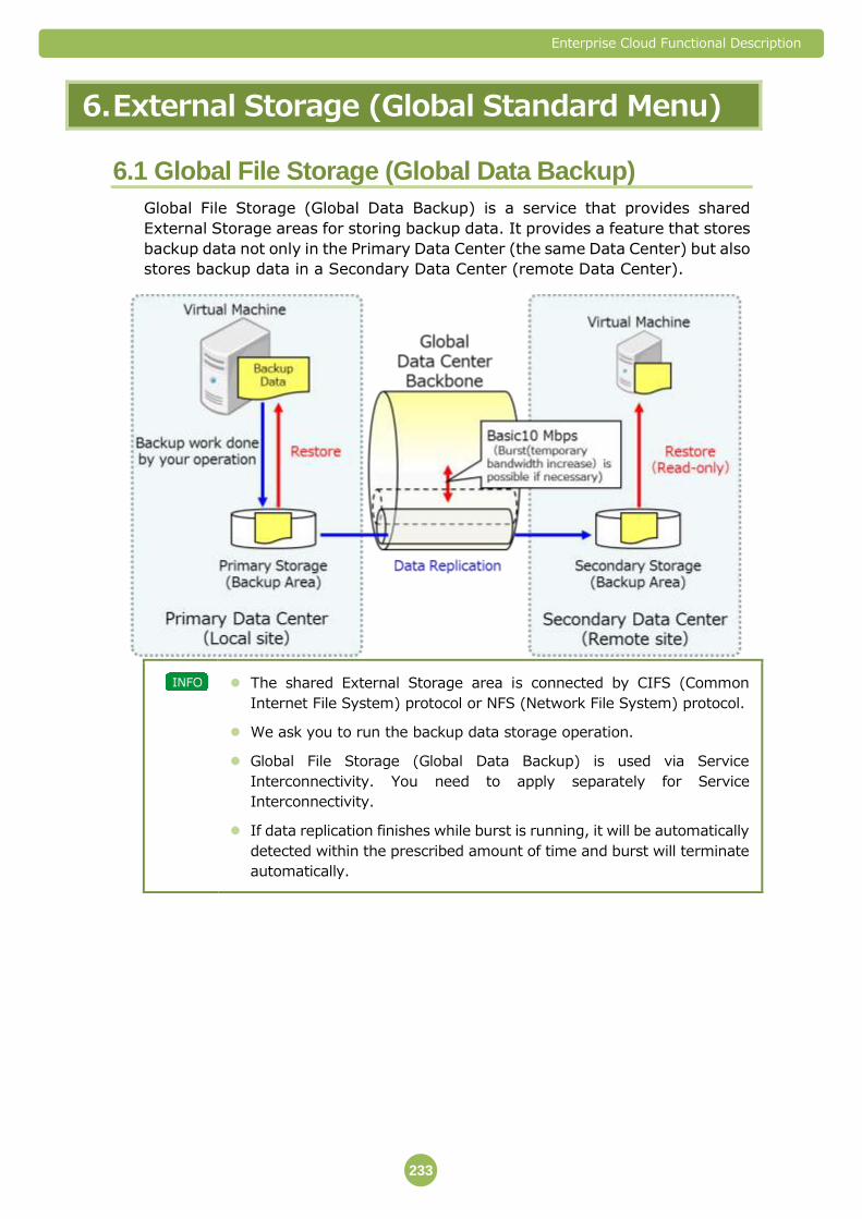
Enterprise Cloud Functional Description
233
6. External Storage (Global Standard Menu)
6.1 Global File Storage (Global Data Backup)
Global File Storage (Global Data Backup) is a service that provides shared
External Storage areas for storing backup data. It provides a feature that stores
backup data not only in the Primary Data Center (the same Data Center) but also
stores backup data in a Secondary Data Center (remote Data Center).
The shared External Storage area is connected by CIFS (Common
Internet File System) protocol or NFS (Network File System) protocol.
We ask you to run the backup data storage operation.
Global File Storage (Global Data Backup) is used via Service
Interconnectivity. You need to apply separately for Service
Interconnectivity.
If data replication finishes while burst is running, it will be automatically
detected within the prescribed amount of time and burst will terminate
automatically.
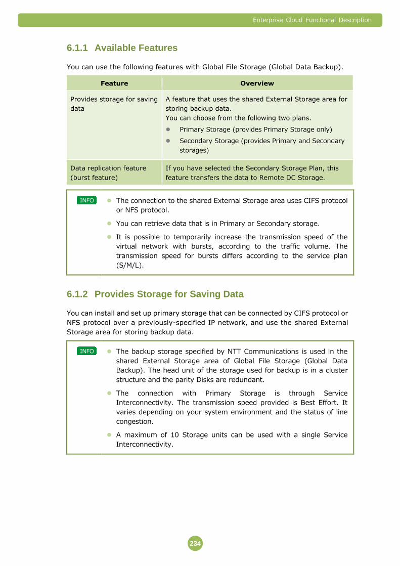
Enterprise Cloud Functional Description
234
Available Features 6.1.1
You can use the following features with Global File Storage (Global Data Backup).
Feature Overview
Provides storage for saving
data
A feature that uses the shared External Storage area for
storing backup data.
You can choose from the following two plans.
Primary Storage (provides Primary Storage only)
Secondary Storage (provides Primary and Secondary
storages)
Data replication feature
(burst feature)
If you have selected the Secondary Storage Plan, this
feature transfers the data to Remote DC Storage.
The connection to the shared External Storage area uses CIFS protocol
or NFS protocol.
You can retrieve data that is in Primary or Secondary storage.
It is possible to temporarily increase the transmission speed of the
virtual network with bursts, according to the traffic volume. The
transmission speed for bursts differs according to the service plan
(S/M/L).
Provides Storage for Saving Data 6.1.2
You can install and set up primary storage that can be connected by CIFS protocol or
NFS protocol over a previously-specified IP network, and use the shared External
Storage area for storing backup data.
The backup storage specified by NTT Communications is used in the
shared External Storage area of Global File Storage (Global Data
Backup). The head unit of the storage used for backup is in a cluster
structure and the parity Disks are redundant.
The connection with Primary Storage is through Service
Interconnectivity. The transmission speed provided is Best Effort. It
varies depending on your system environment and the status of line
congestion.
A maximum of 10 Storage units can be used with a single Service
Interconnectivity.

Enterprise Cloud Functional Description
235
Plans
You can choose from the following Storage plans.
Plans Overview
Primary Storage As backup area, the plan provides only the shared
External Storage area (Primary Storage) inside the same
Data Center (Primary Data Center).
Secondary Storage In addition to the Local DC Storage Plan, the plan provides
a data replication feature. You can transfer data from
Primary Storage to a shared External Storage area
(Secondary Storage) installed in a remote Data Center
(Secondary Data Center).
If you are separately using a Compute Resource at a remote Data
Center, you can retrieve data stored in Secondary Storage from the
remote Data Center via Service Interconnectivity. To use this service,
you must submit an application in writing.
When you connect from the Compute Resource at the remote Data
Center, Secondary Storage is read-only. You cannot store
newly-created data.
You can save to the remote Data Center by connecting between Data
Centers using a virtual network.
It is possible to temporarily increase the transmission speed of the
virtual network with bursts, according to the traffic volume. The
transmission speed for bursts differs according to the service plan
(S/M/L).
Storage Capacity
You can increase or decrease the storage capacity of a single shared External
Storage area within the range listed below.
Lower Limit Upper Limit Setting Unit
Storage Capacity 500 GB 4,000 GB 100 GB
※ 1 GB is 1,024 bytes to the power of 3.
If you reduce storage capacity, you cannot specify a capacity smaller
than the volume of the stored data.

Enterprise Cloud Functional Description
236
Protocol Used
You can choose CIF or NFS as the protocol for connecting to the shared External
Storage area (Primary Storage).
Note that the method for limiting the users who can use the primary storage differs
according to protocol.
Protocol
Used
Protocol
Version
Remarks
NFS NFS version 3 The users who can use Primary Storage are limited
according to the IP address and Server Segment of
the connection source.
CIFS SMB 1.0 or
SMB 2.0
The users who can use Primary Storage are limited
according to WORKGROUP user and password.
If you use CIFS protocol, please set the WORKGROUP user and
password permitting use of Primary Storage according to the rules
specified by NTT Communications.
If you use CIFS protocol, the shared name will be set automatically.
You cannot use both NFS protocol and CIFS protocol for a single
Primary Storage.
Data Replication Feature (Burst Feature) 6.1.3
To manage the remote DC, you can use a data replication feature that synchronizes
data between Primary Storage and Secondary Storage.
The data that is transferred using data replication is differential data
after the time of the previous data synchronization.
Virtual Network Used for Replication
A virtual network is provided to use for replication between Primary Storage and
Secondary Storage.
It is possible to temporarily increase the transmission speed of the virtual network
with bursts, according to the traffic volume. The transmission speed for bursts differs
according to the service plan (S/M/L).
Plans Basic Transmission
Speed
Transmission Speed
During a Burst
S Plan 10 Mbps 50 Mbps
M Plan 10 Mbps 100 Mbps
L Plan 10 Mbps 500 Mbps

Enterprise Cloud Functional Description
237
Note that the basic transmission speed and the transmission speed during a burst
are both provided on a Best Effort basis.
The virtual network for replication is a Best Effort type service that
changes the transmission speed according to your system environment
and line congestion. The actual transmission speed varies according to
the usage of other customers and infrastructure status. The service
does not guarantee transmission speed.
During the period of time that burst is running, a burst charge applies.
It is charged by the minute.
Timing of Data Replication
You can choose from any of the following types of timing for replication from Primary
Storage to Secondary Storage and for burst timing.
Replication Method Timing
Repetition schedule A replication schedule is registered, and replication is run
periodically according to the schedule.
Reserved schedule A date (any 1 date) and time are scheduled, and
replication is run according to the schedule.
Manual immediate
execution
The replication is run by manual operation.
It is not possible to replicate data automatically every time data is
changed.
Restore
Even if the data was replicated from Primary Storage to Secondary Storage, data is
restored manually from the following directories and folders, which were created in
Primary Storage. Note that the directory and folder names will differ according to the
protocol used.
Protocol Used Directory/Folder
NFS .snapshot
CIFS ~snapshot
The data that was last replicated (the same data as that saved in
Secondary Storage) is stored in the above-mentioned directories and
folders.

Enterprise Cloud Functional Description
238
Restore from Secondary Storage to Primary Storage is limited to
situations where the primary Data Center can no longer be used, such
as during disasters, and is executed at the judgment of NTT
Communications.
Important Points 6.1.4
IP Address
It is necessary to allocate an IP Address Block with a Prefix Length of /29 to be used
for Global File Storage (Global Data Backup). The number of IP addresses differs
according to the contracted plan.
Plans Number of
IP Address
Blocks
IP Addresses Allocated from the IP Address Block
Primary
Storage
1 Primary storage IP address
Service Interconnect Gateway IP address
Secondary
Storage(data
storage only)
2 Primary storage IP address
Service Interconnect Gateway IP address
Secondary Storage IP address
Secondary
storage
(when using
stored data at
a remote DC)
3 Primary storage IP address
IP address of the same Data Center's Service
Interconnect Gateway
IP address of the remote Data Center's Service
Interconnect Gateway
Secondary Storage IP address
You cannot change the address block or IP addresses used for the
connection.
Restrictions
Not just Customer-created data is saved in the shared External Storage area of
Primary Storage. Metafiles used for administration are also saved.
The data size of these administration metafiles is also included in the available
capacity of Primary Storage, and this size increases according to the size of your
data and other factors.
You cannot link to a directory service.
The paths for the Primary Storage name and mount are set automatically.
If you delete the existing volume, the administered data is also deleted, and you will
be unable to restore it.
Enterprise Cloud Functional Description
239
The default gateway IP address for Primary Storage is the IP address for the Service
Interconnect Gateway.
You cannot replace Service Interconnectivity once it has been set.
You cannot set the storage capacity and connection protocol separately for Primary
Storage and Secondary Storage. They are automatically set to be the same.
You can specify only one Secondary Storage for one Primary Storage. You cannot
specify multiple secondary storages.
Enterprise Cloud Functional Description
240
7. Security Features (Global Standard Menu)
7.1 IPS/IDS
IPS/IDS is a service that detects and blocks unauthorized access and
cyber-attacks.
IPS/IDS is used via Service Interconnectivity. You need to apply
separately for Service Interconnectivity.
Available Features 7.1.1
The following features are available for IPS/IDS.
Feature Overview
IPS/IDS A feature that detects and blocks unauthorized access and
cyber-attacks on the Virtual Machine.
IPS/IDS Feature 7.1.2
You can choose either IPS mode or IDS mode.
Mode Overview
IPS Unauthorized access and cyber-attacks are detected.
When unauthorized access and cyber-attacks are
detected, traffic is blocked.
IDS Unauthorized access and cyber-attacks are detected.
However, traffic is not blocked even though unauthorized
access and cyber-attacks are detected.
If NTT Communications judges it necessary, we will notify you via
email, etc. of detection and blocking status (bloking notification will be
sent only in IPS mode).
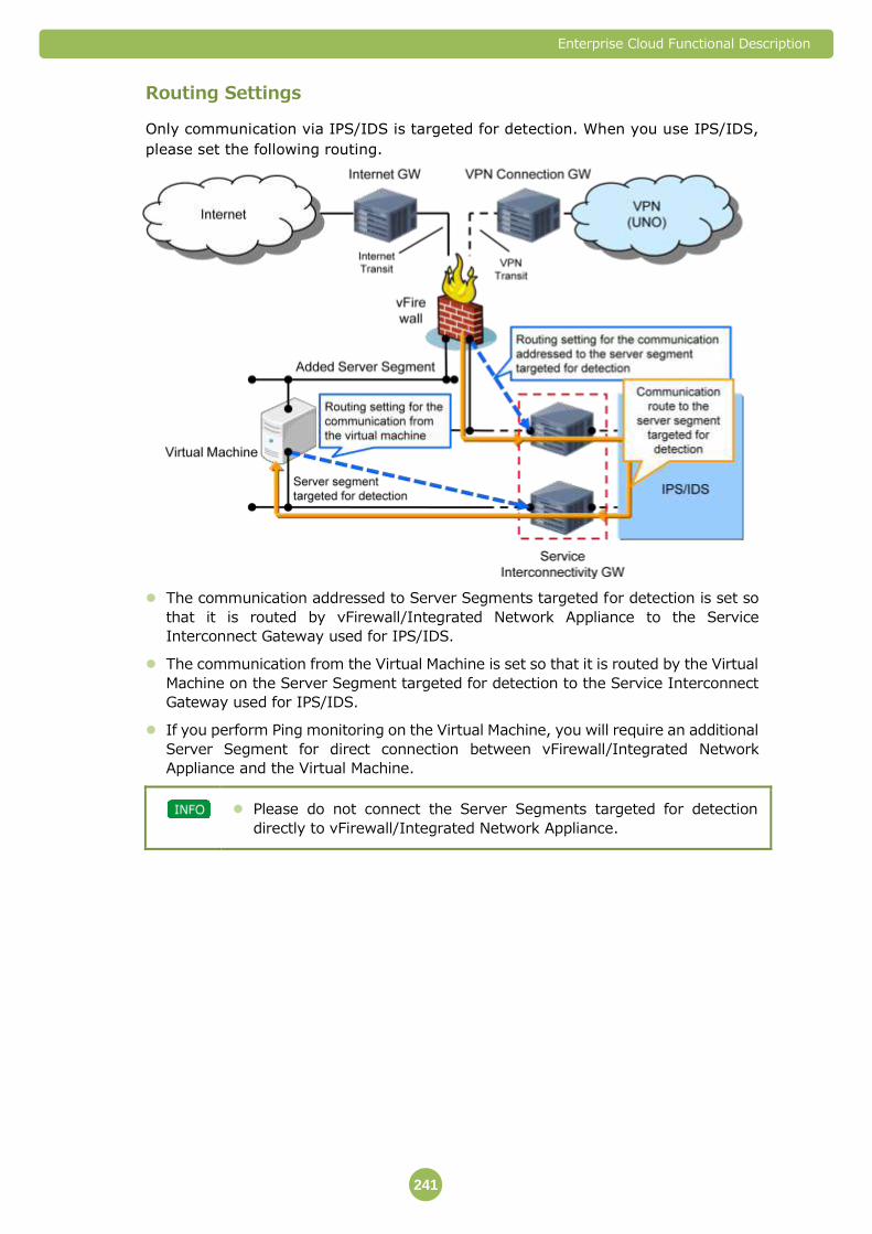
Enterprise Cloud Functional Description
241
Routing Settings
Only communication via IPS/IDS is targeted for detection. When you use IPS/IDS,
please set the following routing.
The communication addressed to Server Segments targeted for detection is set so
that it is routed by vFirewall/Integrated Network Appliance to the Service
Interconnect Gateway used for IPS/IDS.
The communication from the Virtual Machine is set so that it is routed by the Virtual
Machine on the Server Segment targeted for detection to the Service Interconnect
Gateway used for IPS/IDS.
If you perform Ping monitoring on the Virtual Machine, you will require an additional
Server Segment for direct connection between vFirewall/Integrated Network
Appliance and the Virtual Machine.
Please do not connect the Server Segments targeted for detection
directly to vFirewall/Integrated Network Appliance.
Enterprise Cloud Functional Description
242
Analysis Capacity
The traffic volume that can be analyzed by IPS/IDS is shown below.
Item Performance Remarks
Per
service
Maximum
(5 services used)
Traffic Processing
Capacity
200 Mbps 1 Gbps The total value of uplink
and downlink.
Number of
concurrent
sessions
40,000 200,000 The number of sessions
that can be connected
simultaneously.
You can increase the traffic volume up to 1 Gbps, 200,000 sessions
(when 5 services are used) by applying additional services. When using
more than 2 of service, please contact each NTT Communications
affiliate beforehand.
IPS Mode Simulation
Simulation is a process for improving the accuracy of IPS mode for detecting and
blocking unauthorized access and cyber-attacks. You can choose whether to
implement a simulation at the time of application for IPS/IDS. We recommend
implementing it in order to reduce the amount of false positive detections.
If simulation is implemented, a simulation time period is set (approximately 1 – 4
weeks after you start using IPS mode) during which only detection of unauthorized
access and attack traffic is performed and traffic is not blocked. After the simulation
time period, please check to see whether the traffic that IPS/IDS detects as being
targeted for blocking is normal traffic. Based on the results of the check, the IPS/IDS
settings will be adjusted.
Important Points 7.1.3
Used IP Addresses
In order to connect the Service Interconnect Gateway with IPS/IDS, you must have
two IP address blocks available. If the IP address block is already being used, we
might ask you to change it.
NTT Communications will manage the assigned IP address blocks, and assign IP
addresses to the devices that require them.
Restrictions
When the actual traffic volume exceeds the contracted traffic volume, the excess
traffic might be discarded.
Encrypted communication is not targeted for detection or blocking.
Packets which break TCP/UDP/IP protocol rules or abnormal packets are discarded
as a standard function regardless of customer’s configuration.

Enterprise Cloud Functional Description
243
(Examples)
- When the IP header is cut off in the middle
- When the Port number is 0 (zero)
- When the TCP flag combination is abnormal and others
If devices making up this feature are replaced due to malfunction etc., you will not
be able to check device logs or event reports from prior to the replacement via the
Security Web Portal. In addition, if the regular server and the standby server are
switched for a redundantly configured device and they are restored without
replacing the device, you cannot check the log or the event reports for the period
during which the switching occurred from the Security Web Portal.
IPS/IDS do not guarantee that the IPS/IDS feature has integrity or accuracy, or is
suitable for your use. Furthermore, the suitability of the unauthorized/attack traffic
detection algorithms provided by the developers or distributors of the devices
making up the IPS/IDS feature is not guaranteed.
The following information might be provided to the developers or distributors of the
devices making up the IPS/IDS feature.
- Configuration information obtained from providing IPS/IDS
- Information concerning controls etc. for IPS/IDS
We cannot guarantee recovery from failures that might occur due to incompatibility
between IPS/IDS and your environment, or failures that occur due to your
operations other than those specified by NTT Communications.
There may be times when the customer’s environment is affected by maintenance
services. An advance notice will be sent when there are possible effects to the
customer’s environment. This is not applied when we judge the maintenance work
urgent to continue service.
Enterprise Cloud Functional Description
244
7.2 Email Anti-Virus
Email Anti-Virus is a service that detects and blocks viruses that invade via Email
(SMTP communication).
Email-Anti-Virus is used via Service Interconnectivity. You need to
apply separately for Service Interconnectivity.
Available Features 7.2.1
You can use the following features in Email-Anti-Virus.
Feature Overview
Virus scan A feature that monitors email (SMTP communication),
and executes specified processes when viruses are
detected.
Virus Scan Feature 7.2.2
SMTP is the protocol that is targeted for inspection by Email-Anti-Virus.
You can choose the detection and blocking operations. The detection and blocking
processes are shown below.
Item Process Information
Recorded in Logs
Allow Allows communication. None
Alert Monitors email (SMTP), and detects viruses.
However, traffic is not blocked even though
viruses are detected.
Detection Status
Block Monitors email (SMTP), and detects viruses.
Note that communication is blocked when
viruses are detected, and the SMTP Reply Code:
541 is returned to the sender.
Blocking status
If NTT Communications judges it necessary, we will notify you via
email, etc. of the detection and blocking status (for blocking only).

Enterprise Cloud Functional Description
245
Routing Settings
Only communication via Email Anti-Virus is targeted for detection. When you use
Email Anti-Virus, please set the following routing.
The communication addressed to Server Segments targeted for detection is set so
that it is routed by vFirewall/Integrated Network Appliance to the Service
Interconnect Gateway used for Email Anti-Virus.
The communication from the Virtual Machine is set so that it is routed by the Virtual
Machine on the Server Segment targeted for detection to the Service Interconnect
Gateway used for Email Anti-Virus.
If you perform Ping monitoring on the Virtual Machine, you will require an additional
Server Segment for direct connection between vFirewall/Integrated Network
Appliance and the Virtual Machine.
Please do not connect the Server Segments targeted for detection
directly to vFirewall/Integrated Network Appliance.
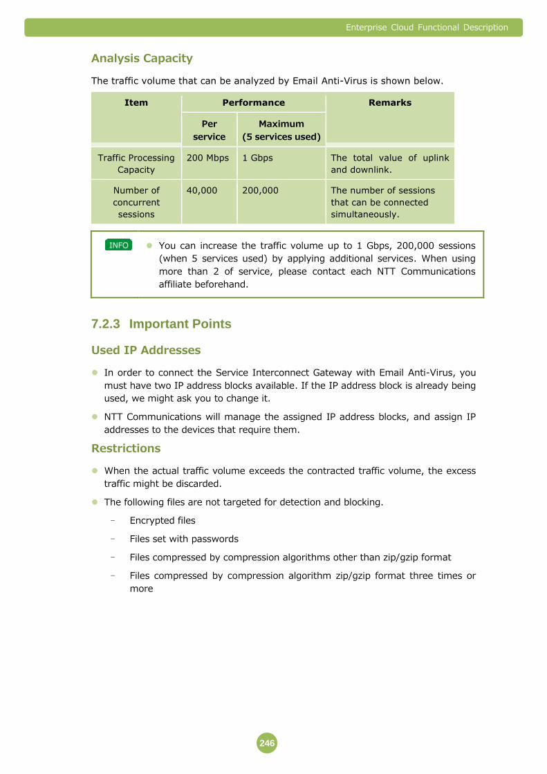
Enterprise Cloud Functional Description
246
Analysis Capacity
The traffic volume that can be analyzed by Email Anti-Virus is shown below.
Item Performance Remarks
Per
service
Maximum
(5 services used)
Traffic Processing
Capacity
200 Mbps 1 Gbps The total value of uplink
and downlink.
Number of
concurrent
sessions
40,000 200,000 The number of sessions
that can be connected
simultaneously.
You can increase the traffic volume up to 1 Gbps, 200,000 sessions
(when 5 services used) by applying additional services. When using
more than 2 of service, please contact each NTT Communications
affiliate beforehand.
Important Points 7.2.3
Used IP Addresses
In order to connect the Service Interconnect Gateway with Email Anti-Virus, you
must have two IP address blocks available. If the IP address block is already being
used, we might ask you to change it.
NTT Communications will manage the assigned IP address blocks, and assign IP
addresses to the devices that require them.
Restrictions
When the actual traffic volume exceeds the contracted traffic volume, the excess
traffic might be discarded.
The following files are not targeted for detection and blocking.
- Encrypted files
- Files set with passwords
- Files compressed by compression algorithms other than zip/gzip format
- Files compressed by compression algorithm zip/gzip format three times or
more

Enterprise Cloud Functional Description
247
Packets which break TCP/UDP/IP protocol rules or abnormal packets are discarded
as a standard function regardless of customer’s configuration.
(Examples)
- When the IP header is cut off in the middle
- When the Port number is 0 (zero)
- When the TCP flag combination is abnormal and others
If devices making up this feature are replaced due to malfunction etc., you will not
be able to check device logs or event reports from prior to the replacement via the
Security Web Portal. In addition, if the regular server and the standby server are
switched for a redundantly configured device and they are restored without
replacing the device, you cannot check the log or the event reports for the period
during which the switching occurred from the Security Web Portal.
Email Anti-Virus does not guarantee that the Email Anti-Virus feature has integrity
or accuracy, or is suitable for your use. Furthermore, the suitability of the virus
identification algorithms provided by the developers or distributors of the devices
making up the Email Anti-Virus feature is not guaranteed.
The following information might be provided to the developers or distributors of the
devices making up the Email Anti-Virus feature.
- Configuration information obtained from providing Email Anti-Virus
- Information concerning inspections etc., for Email Anti-Virus
We cannot guarantee recovery from failures that might occur due to incompatibility
between Email Anti-Virus and your environment, or failures that occur due to your
operations other than those specified by NTT Communications.
There may be times when the customer’s environment is affected by maintenance
services. An advance notice will be sent when there are possible effects to the
customer’s environment. This is not applied when we judge the maintenance work
urgent to continue service.

Enterprise Cloud Functional Description
248
7.3 Web Anti-Virus
Web Anti-Virus is a service that detects and blocks viruses that invade via Web
access (HTTP communication) and FTP communication.
Web Anti-Virus is used via Service Interconnectivity. You need to apply
separately for Service Interconnectivity.
Available Features 7.3.1
You can use the following features in Web Anti-Virus.
Feature Overview
Virus scan A feature that monitors Web access (HTTP communication)
and FTP communication, and executes specified processes
when viruses are detected.
Virus Scan Feature 7.3.2
HTTP and FTP are the protocols targeted for inspection by Web Anti-Virus.
You can choose the detection and blocking operations for each protocol. The
detection and blocking processes are shown below.
Item Process Information
Recorded in Logs
Allow Allows communication. None
Alert Monitors Web access (HTTP communication) and
FTP communication, and detects viruses.
However, traffic is not blocked even though
viruses are detected.
Detection Status
Block Monitors Web access (HTTP communication) and
FTP communication, and detects viruses.
Note that communication is blocked when
viruses are detected, and a blocked screen is
displayed to the user.
Blocking status
If NTT Communications judges it necessary, we will notify you via
email, etc. of the detection and blocking status (for blocking only).
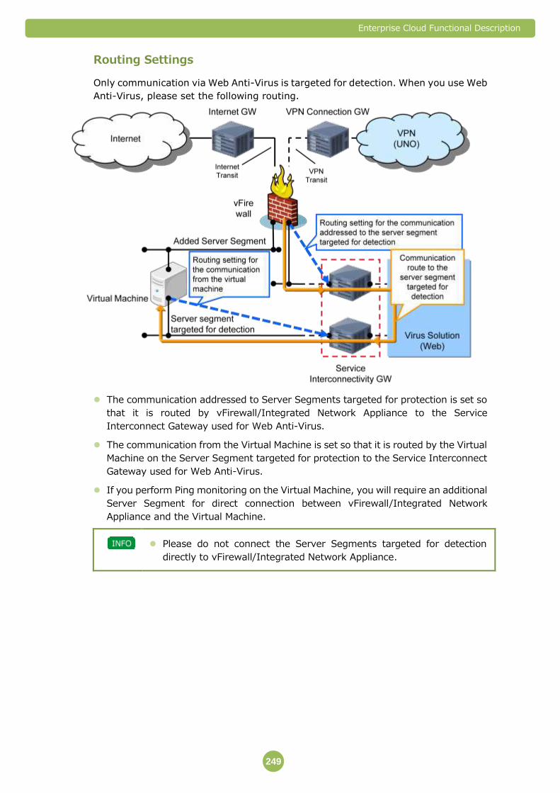
Enterprise Cloud Functional Description
249
Routing Settings
Only communication via Web Anti-Virus is targeted for detection. When you use Web
Anti-Virus, please set the following routing.
The communication addressed to Server Segments targeted for protection is set so
that it is routed by vFirewall/Integrated Network Appliance to the Service
Interconnect Gateway used for Web Anti-Virus.
The communication from the Virtual Machine is set so that it is routed by the Virtual
Machine on the Server Segment targeted for protection to the Service Interconnect
Gateway used for Web Anti-Virus.
If you perform Ping monitoring on the Virtual Machine, you will require an additional
Server Segment for direct connection between vFirewall/Integrated Network
Appliance and the Virtual Machine.
Please do not connect the Server Segments targeted for detection
directly to vFirewall/Integrated Network Appliance.
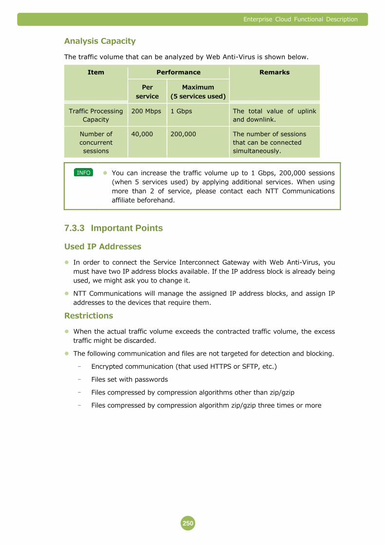
Enterprise Cloud Functional Description
250
Analysis Capacity
The traffic volume that can be analyzed by Web Anti-Virus is shown below.
Item Performance Remarks
Per
service
Maximum
(5 services used)
Traffic Processing
Capacity
200 Mbps 1 Gbps The total value of uplink
and downlink.
Number of
concurrent
sessions
40,000 200,000 The number of sessions
that can be connected
simultaneously.
You can increase the traffic volume up to 1 Gbps, 200,000 sessions
(when 5 services used) by applying additional services. When using
more than 2 of service, please contact each NTT Communications
affiliate beforehand.
Important Points 7.3.3
Used IP Addresses
In order to connect the Service Interconnect Gateway with Web Anti-Virus, you
must have two IP address blocks available. If the IP address block is already being
used, we might ask you to change it.
NTT Communications will manage the assigned IP address blocks, and assign IP
addresses to the devices that require them.
Restrictions
When the actual traffic volume exceeds the contracted traffic volume, the excess
traffic might be discarded.
The following communication and files are not targeted for detection and blocking.
- Encrypted communication (that used HTTPS or SFTP, etc.)
- Files set with passwords
- Files compressed by compression algorithms other than zip/gzip
- Files compressed by compression algorithm zip/gzip three times or more
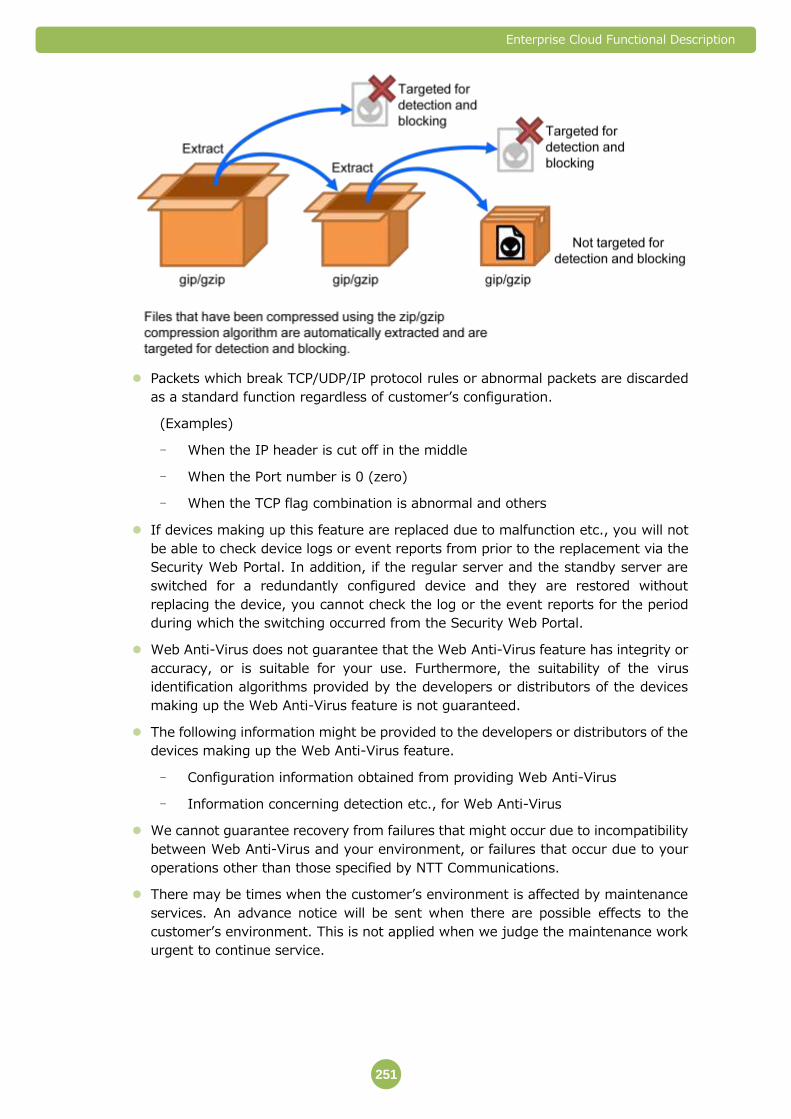
Enterprise Cloud Functional Description
251
Packets which break TCP/UDP/IP protocol rules or abnormal packets are discarded
as a standard function regardless of customer’s configuration.
(Examples)
- When the IP header is cut off in the middle
- When the Port number is 0 (zero)
- When the TCP flag combination is abnormal and others
If devices making up this feature are replaced due to malfunction etc., you will not
be able to check device logs or event reports from prior to the replacement via the
Security Web Portal. In addition, if the regular server and the standby server are
switched for a redundantly configured device and they are restored without
replacing the device, you cannot check the log or the event reports for the period
during which the switching occurred from the Security Web Portal.
Web Anti-Virus does not guarantee that the Web Anti-Virus feature has integrity or
accuracy, or is suitable for your use. Furthermore, the suitability of the virus
identification algorithms provided by the developers or distributors of the devices
making up the Web Anti-Virus feature is not guaranteed.
The following information might be provided to the developers or distributors of the
devices making up the Web Anti-Virus feature.
- Configuration information obtained from providing Web Anti-Virus
- Information concerning detection etc., for Web Anti-Virus
We cannot guarantee recovery from failures that might occur due to incompatibility
between Web Anti-Virus and your environment, or failures that occur due to your
operations other than those specified by NTT Communications.
There may be times when the customer’s environment is affected by maintenance
services. An advance notice will be sent when there are possible effects to the
customer’s environment. This is not applied when we judge the maintenance work
urgent to continue service.
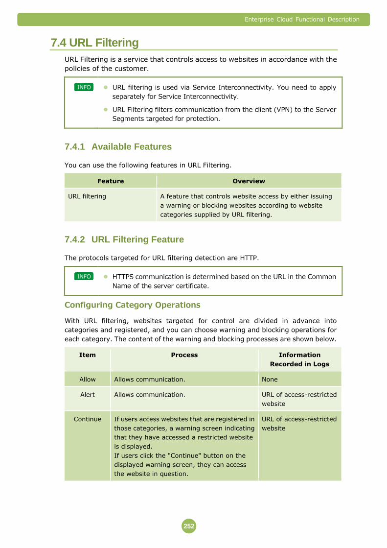
Enterprise Cloud Functional Description
252
7.4 URL Filtering
URL Filtering is a service that controls access to websites in accordance with the
policies of the customer.
URL filtering is used via Service Interconnectivity. You need to apply
separately for Service Interconnectivity.
URL Filtering filters communication from the client (VPN) to the Server
Segments targeted for protection.
Available Features 7.4.1
You can use the following features in URL Filtering.
Feature Overview
URL filtering A feature that controls website access by either issuing
a warning or blocking websites according to website
categories supplied by URL filtering.
URL Filtering Feature 7.4.2
The protocols targeted for URL filtering detection are HTTP.
HTTPS communication is determined based on the URL in the Common
Name of the server certificate.
Configuring Category Operations
With URL filtering, websites targeted for control are divided in advance into
categories and registered, and you can choose warning and blocking operations for
each category. The content of the warning and blocking processes are shown below.
Item Process Information
Recorded in Logs
Allow Allows communication. None
Alert Allows communication. URL of access-restricted
website
Continue If users access websites that are registered in
those categories, a warning screen indicating
that they have accessed a restricted website
is displayed.
If users click the "Continue" button on the
displayed warning screen, they can access
the website in question.
URL of access-restricted
website
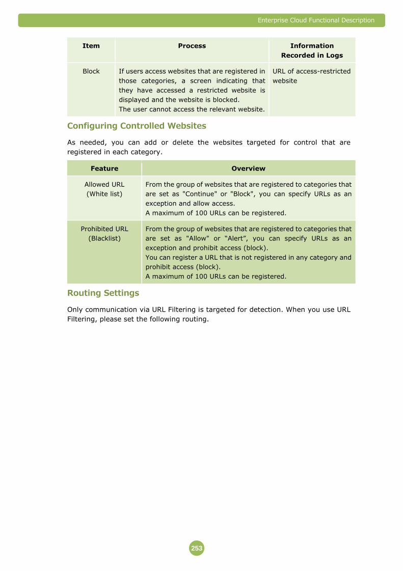
Enterprise Cloud Functional Description
253
Item Process Information
Recorded in Logs
Block If users access websites that are registered in
those categories, a screen indicating that
they have accessed a restricted website is
displayed and the website is blocked.
The user cannot access the relevant website.
URL of access-restricted
website
Configuring Controlled Websites
As needed, you can add or delete the websites targeted for control that are
registered in each category.
Feature Overview
Allowed URL
(White list)
From the group of websites that are registered to categories that
are set as "Continue" or "Block", you can specify URLs as an
exception and allow access.
A maximum of 100 URLs can be registered.
Prohibited URL
(Blacklist)
From the group of websites that are registered to categories that
are set as "Allow" or “Alert”, you can specify URLs as an
exception and prohibit access (block).
You can register a URL that is not registered in any category and
prohibit access (block).
A maximum of 100 URLs can be registered.
Routing Settings
Only communication via URL Filtering is targeted for detection. When you use URL
Filtering, please set the following routing.

Enterprise Cloud Functional Description
254
The communication addressed to Server Segments targeted for detection is set so
that it is routed by vFirewall/Integrated Network Appliance to the Service
Interconnect Gateway used for URL Filtering.
The communication from the Virtual Machine is set so that it is routed by the Virtual
Machine on the Server Segment targeted for detection to the Service Interconnect
Gateway used for URL Filtering.
If you perform Ping monitoring on the Virtual Machine, you will require an additional
Server Segment for direct connection between vFirewall/Integrated Network
Appliance and the Virtual Machine.
Please do not connect the Server Segments targeted for detection
directly to vFirewall/Integrated Network Appliance.
Analysis Capacity
The traffic volume that can be analyzed by URL Filtering is shown below.
Item Performance Remarks
Per
service
Maximum
(5 services used)
Traffic Processing
Capacity
200 Mbps 1 Gbps The total value of uplink
and downlink.
Number of
concurrent
sessions
40,000 200,000 The number of sessions
that can be connected
simultaneously.
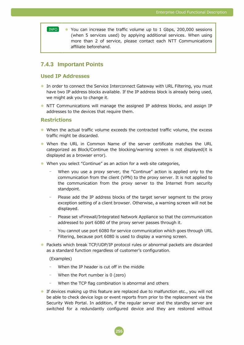
Enterprise Cloud Functional Description
255
You can increase the traffic volume up to 1 Gbps, 200,000 sessions
(when 5 services used) by applying additional services. When using
more than 2 of service, please contact each NTT Communications
affiliate beforehand.
Important Points 7.4.3
Used IP Addresses
In order to connect the Service Interconnect Gateway with URL Filtering, you must
have two IP address blocks available. If the IP address block is already being used,
we might ask you to change it.
NTT Communications will manage the assigned IP address blocks, and assign IP
addresses to the devices that require them.
Restrictions
When the actual traffic volume exceeds the contracted traffic volume, the excess
traffic might be discarded.
When the URL in Common Name of the server certificate matches the URL
categorized as Block/Continue the blocking/warning screen is not displayed(it is
displayed as a browser error).
When you select “Continue” as an action for a web site categories,
- When you use a proxy server, the “Continue” action is applied only to the
communication from the client (VPN) to the proxy server. It is not applied to
the communication from the proxy server to the Internet from security
standpoint.
- Please add the IP address blocks of the target server segment to the proxy
exception setting of a client browser. Otherwise, a warning screen will not be
displayed.
- Please set vFirewall/Integrated Network Appliance so that the communication
addressed to port 6080 of the proxy server passes through it.
- You cannot use port 6080 for service communication which goes through URL
Filtering, because port 6080 is used to display a warning screen.
Packets which break TCP/UDP/IP protocol rules or abnormal packets are discarded
as a standard function regardless of customer’s configuration.
(Examples)
- When the IP header is cut off in the middle
- When the Port number is 0 (zero)
- When the TCP flag combination is abnormal and others
If devices making up this feature are replaced due to malfunction etc., you will not
be able to check device logs or event reports from prior to the replacement via the
Security Web Portal. In addition, if the regular server and the standby server are
switched for a redundantly configured device and they are restored without

Enterprise Cloud Functional Description
256
replacing the device, you cannot check the log or the event reports for the period
during which the switching occurred from the Security Web Portal.
URL Filtering does not guarantee that the URL filtering feature has integrity or
accuracy, or is suitable for your use. Furthermore, the suitability of the URL
identification algorithms provided by the developers or distributors of the devices
making up the URL Filtering feature is not guaranteed.
The following information might be provided to the developers or distributors of the
devices making up the URL Filtering feature.
- Configuration information obtained from providing URL filtering
- Information concerning controls etc., for URL filtering
We cannot guarantee recovery from failures that might occur due to incompatibility
between URL Filtering and your environment, or failures that occur due to your
operations other than those specified by NTT Communications.
There may be times when the customer’s environment is affected by maintenance
services. An advance notice will be sent when there are possible effects to the
customer’s environment. This is not applied when we judge the maintenance work
urgent to continue service.
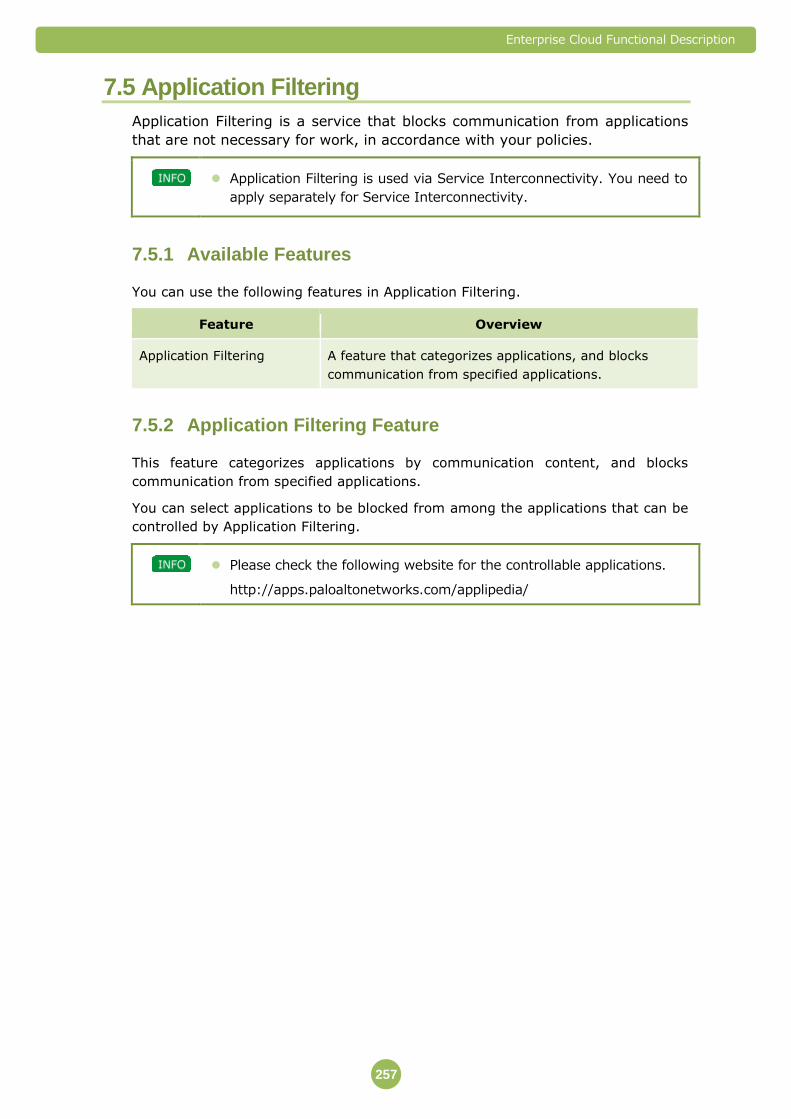
Enterprise Cloud Functional Description
257
7.5 Application Filtering
Application Filtering is a service that blocks communication from applications
that are not necessary for work, in accordance with your policies.
Application Filtering is used via Service Interconnectivity. You need to
apply separately for Service Interconnectivity.
Available Features 7.5.1
You can use the following features in Application Filtering.
Feature Overview
Application Filtering A feature that categorizes applications, and blocks
communication from specified applications.
Application Filtering Feature 7.5.2
This feature categorizes applications by communication content, and blocks
communication from specified applications.
You can select applications to be blocked from among the applications that can be
controlled by Application Filtering.
Please check the following website for the controllable applications.
http://apps.paloaltonetworks.com/applipedia/
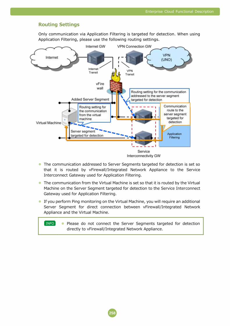
Enterprise Cloud Functional Description
258
Routing Settings
Only communication via Application Filtering is targeted for detection. When using
Application Filtering, please use the following routing settings.
The communication addressed to Server Segments targeted for detection is set so
that it is routed by vFirewall/Integrated Network Appliance to the Service
Interconnect Gateway used for Application Filtering.
The communication from the Virtual Machine is set so that it is routed by the Virtual
Machine on the Server Segment targeted for detection to the Service Interconnect
Gateway used for Application Filtering.
If you perform Ping monitoring on the Virtual Machine, you will require an additional
Server Segment for direct connection between vFirewall/Integrated Network
Appliance and the Virtual Machine.
Please do not connect the Server Segments targeted for detection
directly to vFirewall/Integrated Network Appliance.

Enterprise Cloud Functional Description
259
Analysis Capacity
The traffic volume that can be analyzed by URL Application Filtering is shown below.
Item Performance Remarks
Per
service
Maximum
(5 services used)
Traffic Processing
Capacity
200 Mbps 1 Gbps The total value of uplink
and downlink.
Number of
concurrent
sessions
40,000 200,000 The number of sessions
that can be connected
simultaneously.
You can increase the traffic volume up to 1 Gbps, 200,000 sessions
(when 5 services used) by applying additional services. When using
more than 2 of service, please contact each NTT Communications
affiliate beforehand.
Important Points 7.5.3
Used IP Addresses
In order to connect the Service Interconnect Gateway with Application Filtering, you
must have two IP address blocks available. If the IP address block is already being
used, we might ask you to change it.
NTT Communications will manage the assigned IP address blocks, and assign IP
addresses to the devices that require them.
Restrictions
When the actual traffic volume exceeds the contracted traffic volume, the excess
traffic might be discarded.
Packets which break TCP/UDP/IP protocol rules or abnormal packets are discarded
as a standard function regardless of customer’s configuration.
(Examples)
- When the IP header is cut off in the middle
- When the Port number is 0 (zero)
- When the TCP flag combination is abnormal and others
If devices making up this feature are replaced due to malfunction etc., you will not
be able to check device logs or event reports from prior to the replacement via the
Security Web Portal. In addition, if the regular server and the standby server are
switched for a redundantly configured device and they are restored without
replacing the device, you cannot check the log or the event reports for the period
during which the switching occurred from the Security Web Portal.
Enterprise Cloud Functional Description
260
Application Filtering does not guarantee that the Application Filtering feature has
integrity or accuracy, or is suitable for your use. Furthermore, the suitability of the
application identification algorithms provided by the developers or distributors of the
devices making up the Application Filtering feature is not guaranteed.
The following information might be provided to the developers or distributors of the
devices making up the Application Filtering feature.
- Configuration information obtained from providing application filtering
- Information concerning controls etc., for Application Filtering
We cannot guarantee recovery from failures that might occur due to incompatibility
between Application Filtering and your environment, or failures that occur due to
your operations other than those specified by NTT Communications.
There may be times when the customer’s environment is affected by maintenance
services. An advance notice will be sent when there are possible effects to the
customer’s environment. This is not applied when we judge the maintenance work
urgent to continue service.

Enterprise Cloud Functional Description
261
7.6 Web Application Firewall (WAF)
The Web Application Firewall (WAF) is a service that blocks attack traffic on Web
applications.
Web Application Firewall (WAF) is used via Service Interconnectivity.
You need to apply separately for Service Interconnectivity.
Available Features 7.6.1
You can use the following features in Web Application Firewall (WAF).
Feature Overview
Web Application Firewall This feature detects attack traffic on Web applications,
and blocks attack traffic which has a high probability of
exerting a negative impact.
Web Application Firewall Feature 7.6.2
This feature detects attack traffic on Web applications, and blocks attack traffic
which has a high probability of exerting a negative impact.
If NTT Communications judges it necessary, we will notify you via
email, etc. regarding the detection and blocking status.

Enterprise Cloud Functional Description
262
Routing Settings
Only communication that goes through the Web Application Firewall (WAF) is
targeted for detection. When using Web Application Firewall (WAF), please use the
following routing settings.
The communication that is addressed to the IP address block that is assigned for
connecting to the Web Application Firewall (WAF) is set so that it is routed by
vFirewall/Integrated Network Appliance to the Service Interconnect Gateway used
by Web Application Firewall (WAF).
The communication from the Virtual Machine is set so that it is routed by the Virtual
Machine on the Server Segment targeted for detection to the Service Interconnect
Gateway used for Web Application Firewall (WAF).
If you perform Ping monitoring on the Virtual Machine, you will require an additional
Server Segment for direct connection between vFirewall/Integrated Network
Appliance and the Virtual Machine.
Please do not connect the Server Segments targeted for detection
directly to vFirewall/Integrated Network Appliance.
Enterprise Cloud Functional Description
263
Analysis Capacity
The traffic volume that can be analyzed by Web Application Firewall (WAF) is shown
below.
Item Performance
(maximum
value)
Remarks
Traffic Processing Capacity 1 Gbps The total value of uplink and downlink.
RPS(Request Per Sec) 75,000 rps -
CPS (Connection Per Sec) 10,000 cps -
Active/Standby Structure
The Web Application Firewall (WAF) is configured in an active/standby structure. If a
failure occurs in the active device, the switchover from the active device to the
standby device will be performed automatically.
Staging
Staging is a process that increases the accuracy of detection and blocking of attack
traffic. When you apply for Web Application Firewall (WAF), you can choose whether
to implement staging. We recommend implementing it in order to reduce the
amount of false positive detections.
If staging is implemented, a staging time period is set (approximately 1 – 4 weeks
after you start using IPS mode) during which only detection of attack traffic is
performed and traffic is not blocked. After the staging time period, please check to
see whether the traffic that the Web Application Firewall (WAF) detects as being
targeted for blocking is normal traffic. Based on the results of the confirmation, the
Web Application Firewall (WAF) settings will be adjusted.
Policy
The policy is the defense rules in Web Application Firewall (WAF). By default, one
policy is operated in Web Application Firewall (WAF).
SSL Decryption
You can use the Web Application Firewall (WAF) to decrypt SSL communications and
inspect the communications.
You cannot use the SSLv3 protocol to connect from a client to the Web
Application Firewall (WAF).
If SSL decryption is necessary for WAF inspection, the customer is asked to prepare a
certificate and submit it during the application process. To submit a certificate, take
note of the following instructions:
The customer is asked to acquire a certificate and to perform updates.
Use the PKCS#12 or the PEM format to submit a certificate.
Enterprise Cloud Functional Description
264
A server certificate and key file are both required as a server certificate.
Do not include the route certificate of CA.
If an intermediate certificate and a cross-route certificate are required, store those
certificates as well.
IIS and some systems include a route certificate when exporting an intermediate
certificate etc. at the same time. In this case, please transfer the server certificate
and the intermediate certificate/cross-route certificate separately.
When you send an intermediate certificate and a cross-route certificate separately,
transfer each of them as one file where all necessary certificates are aligned in the
correct order. In this case, you can use the PEM format to transfer them.
When you create a server certificate, it is recommended to protect the file with a password.
(When transferring the server certificate, send the password in a separate message.)
Specify a password in the PKCS#12 type format at the time of creation. Alternatively,
transfer it in the form of a ZIP file encrypted with a password.

Enterprise Cloud Functional Description
265
Important Points 7.6.3
Used IP Addresses
In order to connect the Service Interconnect Gateway with the Web Application
Firewall (WAF), you must have two IP address blocks available.
NTT Communications will manage the assigned IP address blocks, and assign IP
addresses to the devices that require them.
When using Web Application Firewall (WAF), the following address bands cannot be
used in customer networks that connect to Server Segments and Enterprise Cloud to
communicate.
- 172.17.62.0/23
- The address block specified as the HA segment in the WAF redundant
configuration
Restrictions
When the actual traffic volume exceeds the contracted traffic volume, the excess
traffic might be discarded.
The following health check communication is sent from devices that provide the
Web Application Firewall (WAF) feature to a Virtual Machine. In the Virtual Machine
settings, allow communication.
- ICMP
- Health check to L4 (establishing a 3-way handshake)
Web Application Firewall (WAF) does not guarantee that the feature that detects
and blocks attack traffic on Web applications has integrity or accuracy, or is suitable
for your use. Furthermore, the suitability of the signatures (algorithms that judge
the degree of danger and attack traffic) provided by the developers or distributors of
the devices making up the Web Application Firewall (WAF) feature is not
guaranteed.
The following information might be provided to the developers or distributors of the
devices making up the Web Application Firewall (WAF) feature.
- Configuration information obtained from providing Web Application Firewall
(WAF)
- Information obtained from Web Application Firewall (WAF) controls, etc.
We cannot guarantee recovery from failures that might occur due to incompatibility
between Web Application Firewall (WAF) and your environment, or failures that
occur due to your operations other than those specified by NTT Communications.
There may be times when the customer’s environment is affected by maintenance
services. An advance notice will be sent when there are possible effects to the
customer’s environment. This is not applied when we judge the maintenance work
urgent to continue service.
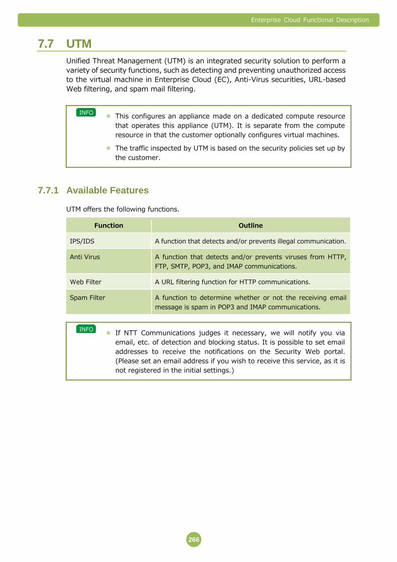
Enterprise Cloud Functional Description
266
7.7 UTM
Unified Threat Management (UTM) is an integrated security solution to perform a
variety of security functions, such as detecting and preventing unauthorized access
to the virtual machine in Enterprise Cloud (EC), Anti-Virus securities, URL-based
Web filtering, and spam mail filtering.
This configures an appliance made on a dedicated compute resource
that operates this appliance (UTM). It is separate from the compute
resource in that the customer optionally configures virtual machines.
The traffic inspected by UTM is based on the security policies set up by
the customer.
Available Features 7.7.1
UTM offers the following functions.
Function Outline
IPS/IDS A function that detects and/or prevents illegal communication.
Anti Virus A function that detects and/or prevents viruses from HTTP,
FTP, SMTP, POP3, and IMAP communications.
Web Filter A URL filtering function for HTTP communications.
Spam Filter A function to determine whether or not the receiving email
message is spam in POP3 and IMAP communications.
If NTT Communications judges it necessary, we will notify you via
email, etc. of detection and blocking status. It is possible to set email
addresses to receive the notifications on the Security Web portal.
(Please set an email address if you wish to receive this service, as it is
not registered in the initial settings.)

Enterprise Cloud Functional Description
267
Routing Settings
The communication addressed to Server Segments targeted for detection is set so
that it is routed by vFirewall/Integrated Network Appliance to UTM.
The communication from the Virtual Machine is set so that it is routed by the
Virtual Machine on the Server Segment targeted for detection to UTM.
If you perform Ping monitoring on the Virtual Machine, you will require an additional
Server Segment for direct connection between vFirewall/Integrated Network
Appliance and the Virtual Machine.
Please do not change default gateway settting by Security Web portal
(Application form is needed).
Please do not connect the server segments targeted for detection
directly to the vFirewall/Integrated Network Appliance.
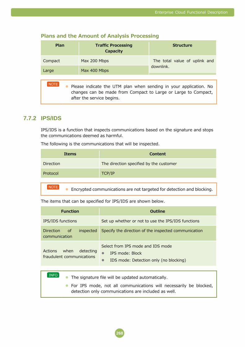
Enterprise Cloud Functional Description
268
Plans and the Amount of Analysis Processing
Plan Traffic Processing
Capacity
Structure
Compact Max 200 Mbps The total value of uplink and
downlink. Large Max 400 Mbps
Please indicate the UTM plan when sending in your application. No
changes can be made from Compact to Large or Large to Compact,
after the service begins.
IPS/IDS 7.7.2
IPS/IDS is a function that inspects communications based on the signature and stops
the communications deemed as harmful.
The following is the communications that will be inspected.
Items Content
Direction The direction specified by the customer
Protocol TCP/IP
Encrypted communications are not targeted for detection and blocking.
The items that can be specified for IPS/IDS are shown below.
Function Outline
IPS/IDS functions Set up whether or not to use the IPS/IDS functions
Direction of inspected
communication
Specify the direction of the inspected communication
Actions when detecting
fraudulent communications
Select from IPS mode and IDS mode
IPS mode: Block
IDS mode: Detection only (no blocking)
The signature file will be updated automatically.
For IPS mode, not all communications will necessarily be blocked,
detection only communications are included as well.

Enterprise Cloud Functional Description
269
Anti Virus 7.7.3
Anti-Virus is a function that inspects communications based on the pattern file and
prevents communications that are detected as viruses.
The following are the communications and files that will be inspected.
Items Content
Communicat
ions
Direction The direction specified by the customer
Protocol The protocols specified by the customer from HTTP, FTP,
SMTP, POP3, and IMAP
Port Number The port number specified by the customer
File File Size Files that are 3MB and under
Compressed
files
Number of
times
Inspects only files that have been compressed 12 times or
less
Format arj, cab, gzip, lha, lzh, msc, rar, tar, zip
File size Inspects only files with extracted file size of 3MB or less
Files other than the above (such as encrypted files and files with
passwords) are not inspected.
Files that are not subject to inspection will pass through.
The items that can be specified for Anti-Virus are shown below.
Items Content
Anti Virus function Set up whether or not to use the Anti-Virus function
Communi
cations
Direction Specify the direction of the inspected communication
Protocol Select the protocols from HTTP, FTP, SMTP, POP3, and IMAP
Port
number
Specify the port number of each protocol
Actions when detecting
viruses
Select from “Anti Virus Block” and “AntiVirus_Monitor”
AntiVirus_Block: Blocks the communication when viruses
are detected
AntiVirus_Monitor: Detects viruses only (but does not
block)
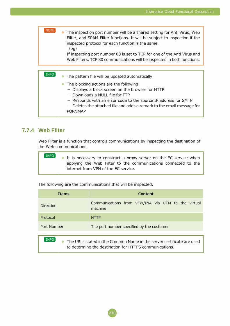
Enterprise Cloud Functional Description
270
The inspection port number will be a shared setting for Anti Virus, Web
Filter, and SPAM Filter functions. It will be subject to inspection if the
inspected protocol for each function is the same.
(eg)
If inspecting port number 80 is set to TCP for one of the Anti Virus and
Web Filters, TCP 80 communications will be inspected in both functions.
The pattern file will be updated automatically
The blocking actions are the following:
- Displays a block screen on the browser for HTTP
- Downloads a NULL file for FTP
- Responds with an error code to the source IP address for SMTP
- Deletes the attached file and adds a remark to the email message for
POP/IMAP
Web Filter 7.7.4
Web Filter is a function that controls communications by inspecting the destination of
the Web communications.
It is necessary to construct a proxy server on the EC service when
applying the Web Filter to the communications connected to the
internet from VPN of the EC service.
The following are the communications that will be inspected.
Items Content
Direction Communications from vFW/INA via UTM to the virtual
machine
Protocol HTTP
Port Number The port number specified by the customer
The URLs stated in the Common Name in the server certificate are used
to determine the destination for HTTPS communications.
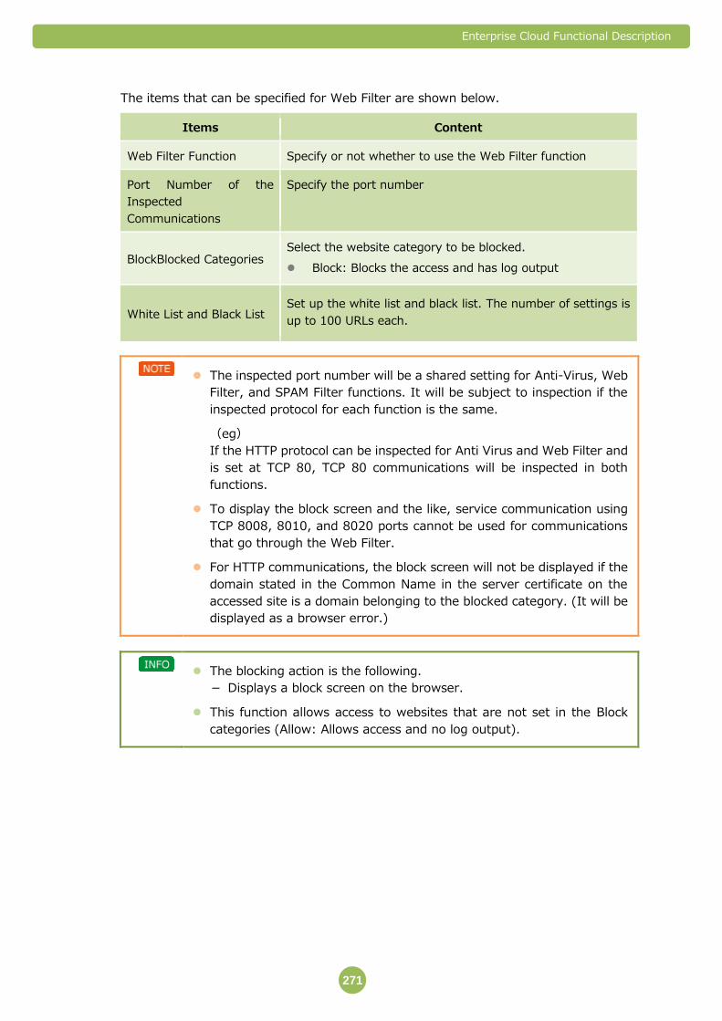
Enterprise Cloud Functional Description
271
The items that can be specified for Web Filter are shown below.
Items Content
Web Filter Function Specify or not whether to use the Web Filter function
Port Number of the
Inspected
Communications
Specify the port number
BlockBlocked Categories Select the website category to be blocked.
Block: Blocks the access and has log output
White List and Black List Set up the white list and black list. The number of settings is
up to 100 URLs each.
The inspected port number will be a shared setting for Anti-Virus, Web
Filter, and SPAM Filter functions. It will be subject to inspection if the
inspected protocol for each function is the same.
(eg)
If the HTTP protocol can be inspected for Anti Virus and Web Filter and
is set at TCP 80, TCP 80 communications will be inspected in both
functions.
To display the block screen and the like, service communication using
TCP 8008, 8010, and 8020 ports cannot be used for communications
that go through the Web Filter.
For HTTP communications, the block screen will not be displayed if the
domain stated in the Common Name in the server certificate on the
accessed site is a domain belonging to the blocked category. (It will be
displayed as a browser error.)
The blocking action is the following.
- Displays a block screen on the browser.
This function allows access to websites that are not set in the Block
categories (Allow: Allows access and no log output).
Enterprise Cloud Functional Description
272
Spam Filter 7.7.5
Spam Filter is a function that determines spam mail by inspecting the email
communications.
The following are the communications that will be inspected.
Items Content
Direction Direction specified by the customer
Protocol POP3 and IMAP
Port Number Port number specified by the customer
The items that can be specified for Spam Filter are shown below.
Items Content
Spam Filter function Set up whether or not to use the Spam Filter function
Communi
cations
Direction Specify the direction of the inspected communications
Port
Number
Specify the port number for each protocol
White List and Black List Set up the white list and black list. The number of settings is up
to 100 URLs each
The inspected port number will be a shared setting for Anti Virus, Web
Filter, and SPAM Filter functions. It will be subject to inspection if the
inspected protocol for each function is the same.
(eg)
If the IMAP protocol can be inspected for Anti-Virus and Web Filter and
is set at TCP 143, TCP 143 communications will be inspected in both
functions.
When the message is determined as spam, ‘Spam’ will be added in the
email subject. The customer, who receives an email message with the
subject title ‘Spam’, will need to deal with the message as nothing will
be done by Spam Filter after the message is determined as spam.
For IMAP, there are times when ‘Spam’ cannot be added in the email
subject title. This is not caused by UTM specification but a restriction by
IMAP action. For IMAP, an email subject title is downloaded on the client
first and a message body is downloaded next. So when it is determined
as spam due to an URL in the message body, ‘Spam’ cannot be added in
the email subject title. With IMAP, it is possible to add ‘Spam’ on the
email subject title when the email address is determined to be spam.
Enterprise Cloud Functional Description
273
Important Points 7.7.6
Restrictions in non-Japanese Data Centers
One global IP address per one UTM service is necessarily assigned to monitoring use
for UTM server. When you order 2 UTM services, two global IP addresses are
assigned by NTT operator. Therefore please make sure that you prepare the
required quantity of global IP addresses when ordering.
Do not change NAT rules for UTM service configured to vFW/INA by NTT Com
Group.
IP Address
IP address set as Default gateway in Server Segment setting cannot be assigned on
UTM interface.
Restrictions
It is absolutely necessary to have a contract for either vFirewall or Integrated
Network Appliance.
The appliance that runs this service operates on a single structure. The platform is
a dual configuration where it will switch in five to ten minutes after rebooting on
the backup platform during failures.
This service needs a dedicated compute resource pool. (The pool will be designed
when applying for UTM.) This service cannot be configured on an existing compute
resource pool.
Customers cannot configure a virtual machine on the compute resource pool
operating this service.
The dedicated compute resource pool for this service cannot be extended or
reduced.
Changes in resource allocations for the virtual machine that operates this service
cannot be done from the customer portal. (Only we can change it as it is virtual
machine controlled by us.)
It will switch to a conserve (Protect) mode when the usage rate of the UTM
memory exceeds 80 percent. It will pass without inspecting new sessions when it
is in conserve mode (for Anti-Virus, Web Filter, and Spam Filter functions). Also
conserve mode will automatically be released when the memory usage rate is 80
percent and under.
The virtual machine operating the UTM cannot use private catalogues, backup and
VM security services.
Packets which break TCP/UDP/IP protocol rules or abnormal packets are discarded
as a standard function regardless of customer’s configuration.
(examples)
- When the IP header is cut off in the middle
- When the port number is 0 (zero)
- When the TCP flag combination is abnormal and others

Enterprise Cloud Functional Description
274
- Illegal packets due to encapsulation and others
UTM does not guarantee that the UTM feature has integrity or accuracy, or is
suitable for your use. Furthermore, the suitability of the algorithms that detect
unauthorized/cyber-attack communications provided by the developers or
distributors of the devices making up the UTM feature is not guaranteed.
The following information might be provided to the developers or the distributors
of the devices making up UTM features.
- Configuration information obtained through providing UTM
- Information on UTM control
We cannot guarantee recovery from failures that might occur due to
incompatibility between UTM and your environment, or failures that occur due to
your operations other than those specified by NTT Communications.
There may be times when the customer’s environment is affected by maintenance
services. An advance notice will be sent when there are possible effects to the
customer’s environment. This is not applied when we judge the maintenance work
urgent to continue service.
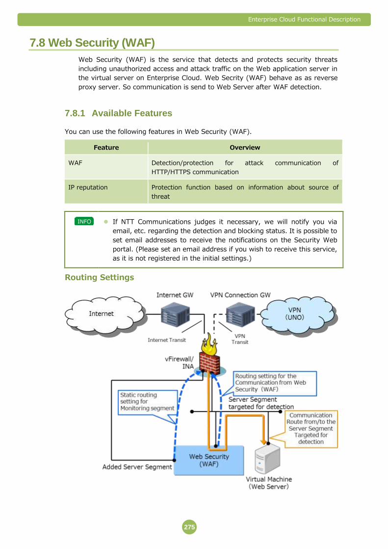
Enterprise Cloud Functional Description
275
7.8 Web Security (WAF)
Web Security (WAF) is the service that detects and protects security threats
including unauthorized access and attack traffic on the Web application server in
the virtual server on Enterprise Cloud. Web Secrity (WAF) behave as as reverse
proxy server. So communication is send to Web Server after WAF detection.
Available Features 7.8.1
You can use the following features in Web Security (WAF).
Feature Overview
WAF Detection/protection for attack communication of
HTTP/HTTPS communication
IP reputation Protection function based on information about source of
threat
If NTT Communications judges it necessary, we will notify you via
email, etc. regarding the detection and blocking status. It is possible to
set email addresses to receive the notifications on the Security Web
portal. (Please set an email address if you wish to receive this service,
as it is not registered in the initial settings.)
Routing Settings
Enterprise Cloud Functional Description
276
To inspect Web communication, communications with the Web server to be
inspected need to be set to communicate with the virtual server of the Web
Security (WAF) by using vFirewall/integrated network appliance.
For setting of communications from Web Security (WAF) to Web server, the real
server of Web Security (WAF) needs to be configured on the security portal.
For monitoring on Web Securty (WAF), you will require an additional Server
Segment for direct connection between vFirewall/Integrated Network Appliance.
Plans and the Amount of Analysis Processing
Plan Traffic processing capacity Structure
Entry Max 50 Mbps This is the total value of uplink
and downlink on a Best Effort
basis. Compact Max 200 Mbps
Large Max 400 Mbps
Please indicate the Web Security (WAF) plan when sending in your
application. No changes can be made among Entry, Compact and Large
after the service begins.
WAF 7.8.2
WAF function is the function that inspects Web communication specified by customer
and detects/protects unauthorized access and attack traffic.
Communications to be inspected are as follows.
Item Details
Protocol HTTP/HTTPS
Detailed functions are as follows.
Items Details
WAF function
This function inspects Web communications based on the
signature.
This function protects the Web server from various attacks
from the application layer including cross-site scripting, SQL
injection and buffer overflow.
Trust/Black IP control
function
It is possible to control communications of the IP address
specified by customer.
It is possible to specify Trust IP (IP address that is allowed
unconditionally) and Black IP (IP address that is blocked
unconditionally). A maximum of 100 addresses can be
registered for Trust IP and Black IP in total.
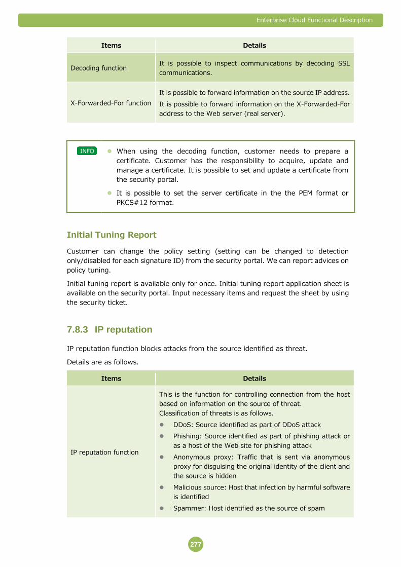
Enterprise Cloud Functional Description
277
Items Details
Decoding function It is possible to inspect communications by decoding SSL
communications.
X-Forwarded-For function
It is possible to forward information on the source IP address.
It is possible to forward information on the X-Forwarded-For
address to the Web server (real server).
When using the decoding function, customer needs to prepare a
certificate. Customer has the responsibility to acquire, update and
manage a certificate. It is possible to set and update a certificate from
the security portal.
It is possible to set the server certificate in the the PEM format or
PKCS#12 format.
Initial Tuning Report
Customer can change the policy setting (setting can be changed to detection
only/disabled for each signature ID) from the security portal. We can report advices on
policy tuning.
Initial tuning report is available only for once. Initial tuning report application sheet is
available on the security portal. Input necessary items and request the sheet by using
the security ticket.
IP reputation 7.8.3
IP reputation function blocks attacks from the source identified as threat.
Details are as follows.
Items Details
IP reputation function
This is the function for controlling connection from the host
based on information on the source of threat.
Classification of threats is as follows.
DDoS: Source identified as part of DDoS attack
Phishing: Source identified as part of phishing attack or
as a host of the Web site for phishing attack
Anonymous proxy: Traffic that is sent via anonymous
proxy for disguising the original identity of the client and
the source is hidden
Malicious source: Host that infection by harmful software
is identified
Spammer: Host identified as the source of spam
Enterprise Cloud Functional Description
278
IP reputation function works as the standard function so that this
function cannot be enabled or disabled.
Important Points 7.8.4
Restrictions in non-Japanese Data Centers
One global IP address per one Web Security (WAF) service is necessarily assigned to
monitoring use for Web Security (WAF) server. When you order 2 Web Security
(WAF) services, two global IP addresses are assigned by NTT operator. Therefore
please make sure that you prepare the required quantity of global IP addresses
when ordering.
Do not change NAT rules for Web Security (WAF) service configured to vFW/INA by
NTT Com Group.
Used IP Addresses
IP address set as Default gateway in Server Segment setting cannot be assigned on
Web Security (WAF) interface.
Restrictions
You must first register the Virtual Server IP address as Reserved IP. Reserved IP
addresses are set by the Customer Portal.
You are responsible for IP address design in Server Segment. NTT Communications
assumes no responsibility for any failures that may occur due to IP design problems.
Communication that can be handled with this service is Web communication only.
Communications other than HTTP, including FTP and SSH, cannot be handled.
If the protocol that complies with RFC or encapsulation is used, communications
cannot be processed with this service.
The appliance that runs this service operates on a single structure. The platform is a
dual configuration where it will switch in five to ten minutes after rebooting on the
backup platform during failures.
This service needs a dedicated compute resource pool. (The pool will be created
when applying for Web Security (WAF).) This service cannot be configured on an
existing compute resource pool.
Customers cannot configure a virtual machine on the compute resource pool
operating this service.
The dedicated compute resource pool for this service cannot be extended or
reduced.
Enterprise Cloud Functional Description
279
Changes in resource allocations for the virtual machine that operates this service
cannot be done from the customer portal. (Only we can operate it as it is virtual
server controlled by us.)
The virtual machine operating the Web Security (WAF) cannot use private
catalogues, backup and VM security services.
We do not guarantee that features provided by Web Security (WAF) have integrity
or accuracy, or they are suitable for your use. Furthermore, the suitability of the
algorithms that detect unauthorized/cyber-attack communications provided by the
developers or distributors of the devices making up the Web Security (WAF) feature
is not guaranteed.
The following information might be provided to the developers or the distributors of
the devices making up Web Security (WAF) features.
- Configuration information obtained through providing Web Security (WAF)
- Information on control of Web Security (WAF)
We cannot guarantee recovery from failures that might occur due to incompatibility
between the Web Security (WAF) feature and your environment, or failures that
occur due to your operations other than those specified by NTT Communications.
There may be times when the customer’s environment is affected by maintenance
services. An advance notice will be sent when there are possible effects to the
customer’s communication. This is not applied when we judge the maintenance
work urgent to provide the service.
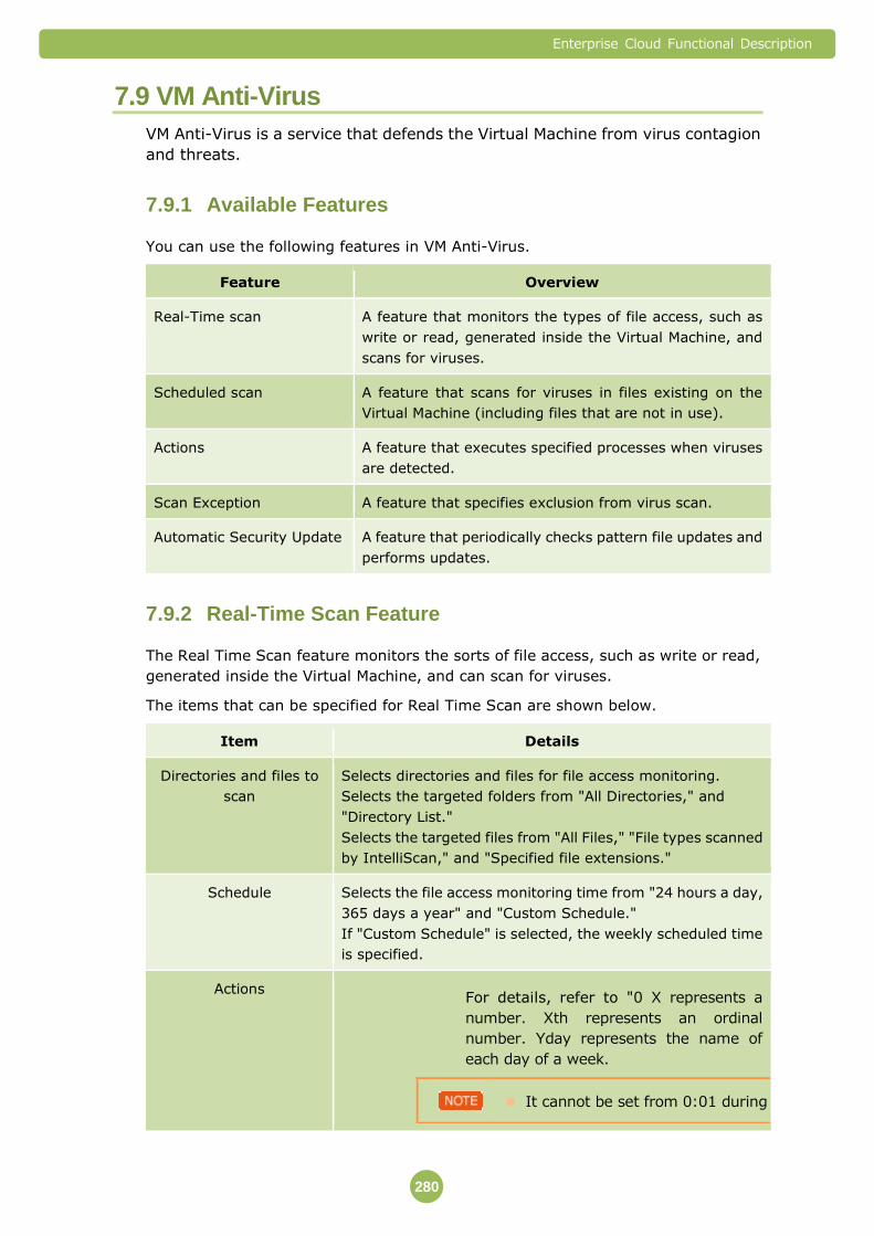
Enterprise Cloud Functional Description
280
7.9 VM Anti-Virus
VM Anti-Virus is a service that defends the Virtual Machine from virus contagion
and threats.
Available Features 7.9.1
You can use the following features in VM Anti-Virus.
Feature Overview
Real-Time scan A feature that monitors the types of file access, such as
write or read, generated inside the Virtual Machine, and
scans for viruses.
Scheduled scan A feature that scans for viruses in files existing on the
Virtual Machine (including files that are not in use).
Actions A feature that executes specified processes when viruses
are detected.
Scan Exception A feature that specifies exclusion from virus scan.
Automatic Security Update A feature that periodically checks pattern file updates and
performs updates.
Real-Time Scan Feature 7.9.2
The Real Time Scan feature monitors the sorts of file access, such as write or read,
generated inside the Virtual Machine, and can scan for viruses.
The items that can be specified for Real Time Scan are shown below.
Item Details
Directories and files to
scan
Selects directories and files for file access monitoring.
Selects the targeted folders from "All Directories," and
"Directory List."
Selects the targeted files from "All Files," "File types scanned
by IntelliScan," and "Specified file extensions."
Schedule Selects the file access monitoring time from "24 hours a day,
365 days a year" and "Custom Schedule."
If "Custom Schedule" is selected, the weekly scheduled time
is specified.
Actions For details, refer to "0 X represents a
number. Xth represents an ordinal
number. Yday represents the name of
each day of a week.
It cannot be set from 0:01 during 0:59 in scheduled scan.

Enterprise Cloud Functional Description
281
Item Details
Actions"
(⇒P.280).
Scan Exceptions For details, refer to "7.9.5 Scan Exception Feature"
(⇒P .283).
Real-time scan is only provided for the Windows OS. It cannot be used
in Linux OS.
Scheduled Scan Feature 7.9.3
You can scan for viruses in files existing on the Virtual Machine (including files that
are not in use) according to a specified schedule.
The items that can be specified for the Scheduled Scan Feature are shown below.
Item Details
Directories and files to
scan
Selects folders and files for file access monitoring.
Selects the targeted folders from "All directories," and
"Directory List."
Selects the targeted files from "All Files," "File types scanned
by IntelliScan," and "Specified file extensions."
Schedule Selects the interval the scheduled scan runs from “Daily”
“Weekly” or “Monthly,” and specifies the targeted time.
Daily: Specifies either "Every Day," "Weekdays," or "Every X
Days."
Weekly: Specifies either "Y day of each week" or "Y day of
every X Weeks."
Monthly: Specifies either "The Xth of each month" or " Y day of
the Xth week of each month."
Actions For details, refer to "0 X represents a
number. Xth represents an ordinal
number. Yday represents the name of
each day of a week.
It cannot be set from 0:01 during 0:59 in scheduled scan.
Actions" (->P.280).
Scan Exceptions For details, refer to "7.9.5 Scan Exception Feature" (⇒P.283).
X represents a number. Xth represents an ordinal number. Yday represents
the name of each day of a week.

Enterprise Cloud Functional Description
282
It cannot be set from 0:01 during 0:59 in scheduled scan.
Actions 7.9.4
You can set the processing method for the case where files that are infected by
viruses are detected.
You can specify "Recommended Setting" or "Custom Setting."
Item Details
Recommended setting
(Use action determined by
ActiveAction)
The virus processing method recommended by the
developers and distributors of the devices making up the
VM Anti-Virus feature.
Custom setting The first process (primary process) when viruses are
detected is specified from “Delete,” “Clean,” “Pass,”
“Deny access” and “Quarantine.”
The "recommended setting" virus processing method might be
modified according to day-to-day operation, and the information
concerning the handling method is not disclosed.
Custom Setting
Any of the following can be specified as the first process (primary process) when
viruses are detected. Note that the processing might differ depending on the Virtual
Machine OS.
Item Primary Process Details Secondary
Process Details
(Process when
the primary
process failed)
Notification
by email, etc. For Windows For Linux
Delete The same
process as
"Quarantine" is
performed.
The files that are
infected by
viruses are
deleted.
The same
process as
"Quarantine" is
performed.
Notification is
made when the
secondary
process fails.
Clean The viruses are removed from the
files that are infected with viruses,
and they return to the
pre-contamination state.
The same
process as
"Quarantine" is
performed.
Notification is
made when the
secondary
process fails.
Pass It is registered in the detection log.
It does not take any action against
the infected files.
The secondary
process is not
performed.
Notification is
made when
viruses are
detected.
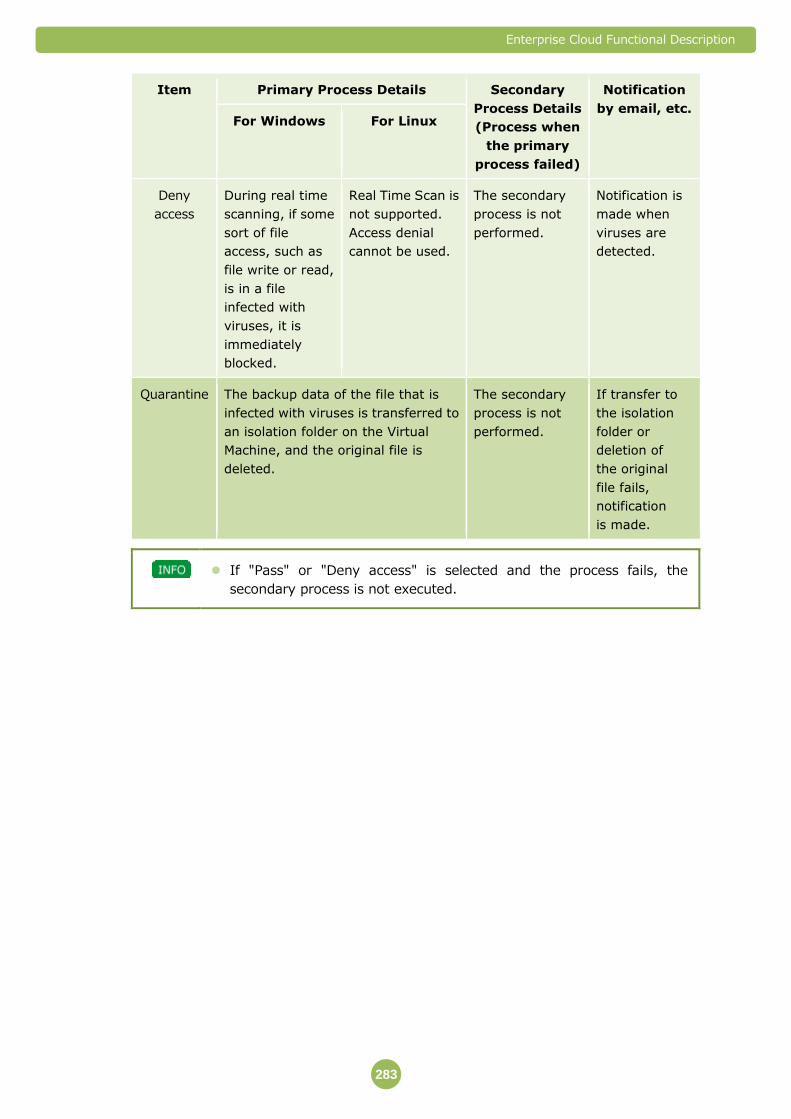
Enterprise Cloud Functional Description
283
Item Primary Process Details Secondary
Process Details
(Process when
the primary
process failed)
Notification
by email, etc. For Windows For Linux
Deny
access
During real time
scanning, if some
sort of file
access, such as
file write or read,
is in a file
infected with
viruses, it is
immediately
blocked.
Real Time Scan is
not supported.
Access denial
cannot be used.
The secondary
process is not
performed.
Notification is
made when
viruses are
detected.
Quarantine The backup data of the file that is
infected with viruses is transferred to
an isolation folder on the Virtual
Machine, and the original file is
deleted.
The secondary
process is not
performed.
If transfer to
the isolation
folder or
deletion of
the original
file fails,
notification
is made.
If "Pass" or "Deny access" is selected and the process fails, the
secondary process is not executed.

Enterprise Cloud Functional Description
284
Scan Exception Feature 7.9.5
By specifying directories, files and extensions, you can specify files that will not be
scanned for viruses.
Pattern File Automatic Update Feature 7.9.6
This feature checks periodically for pattern file update information on NTT
Communications administration server, and updates pattern files automatically if
there are updates available.
Time Periods When Pattern File Automatic Updates will be run
Selects the schedule for the pattern file automatic updates, from "Daily" "Weekly" or
"Monthly," and specifies the targeted time.
Item Details
Hourly Specifies "X minute every hour."
Daily Specifies either "Every Day," "Weekdays," or "Every X Days."
Weekly Specifies either "Y day of each week" or "Yday of every X weeks."
Monthly Specifies either "The Xth of each month" or "Y day of the Xth
week of each month."
※ X represents a number. Xth represents an ordinal number. Yday represents
the name of each day of a week.
Important Points 7.9.7
Virtual Machine System Requirements
The system requirements (Memory capacity, Disk capacity, and OS) for the software
agent that uses VM Anti-Virus are shown below.
Item Overview
Memory capacity 512 MB or greater
Disk capacity 1 GB or greater
OS The OSs listed in "Supported OS List of VM Anti-Virus, VM
Virtual Patch, and VM Firewall" of the available OSs in Enterprise
Cloud
When using Linux OS, it is necessary to confirm the kernel version.
Please set IPv6 to ON or OFF correctly on Guest OS when using VM
Anti-Virus.
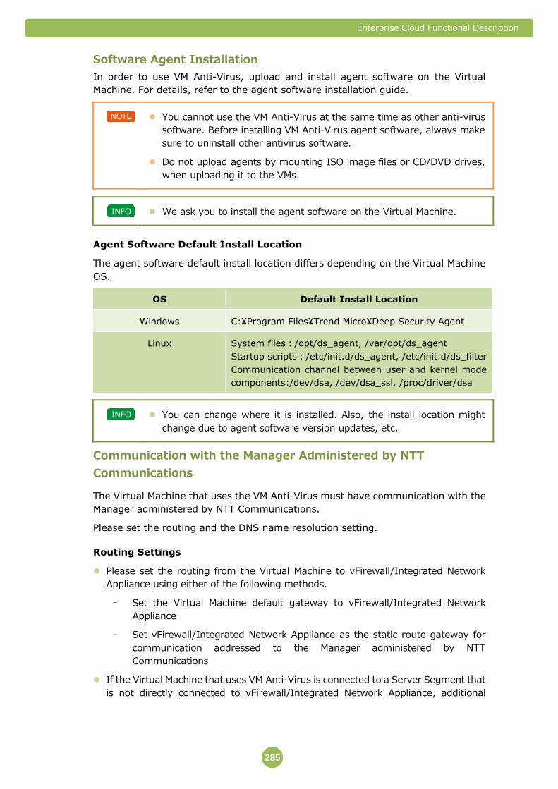
Enterprise Cloud Functional Description
285
Software Agent Installation
In order to use VM Anti-Virus, upload and install agent software on the Virtual
Machine. For details, refer to the agent software installation guide.
You cannot use the VM Anti-Virus at the same time as other anti-virus
software. Before installing VM Anti-Virus agent software, always make
sure to uninstall other antivirus software.
Do not upload agents by mounting ISO image files or CD/DVD drives,
when uploading it to the VMs.
We ask you to install the agent software on the Virtual Machine.
Agent Software Default Install Location
The agent software default install location differs depending on the Virtual Machine
OS.
OS Default Install Location
Windows C:¥Program Files¥Trend Micro¥Deep Security Agent
Linux System files:/opt/ds_agent, /var/opt/ds_agent
Startup scripts:/etc/init.d/ds_agent, /etc/init.d/ds_filter
Communication channel between user and kernel mode
components:/dev/dsa, /dev/dsa_ssl, /proc/driver/dsa
You can change where it is installed. Also, the install location might
change due to agent software version updates, etc.
Communication with the Manager Administered by NTT
Communications
The Virtual Machine that uses the VM Anti-Virus must have communication with the
Manager administered by NTT Communications.
Please set the routing and the DNS name resolution setting.
Routing Settings
Please set the routing from the Virtual Machine to vFirewall/Integrated Network
Appliance using either of the following methods.
- Set the Virtual Machine default gateway to vFirewall/Integrated Network
Appliance
- Set vFirewall/Integrated Network Appliance as the static route gateway for
communication addressed to the Manager administered by NTT
Communications
If the Virtual Machine that uses VM Anti-Virus is connected to a Server Segment that
is not directly connected to vFirewall/Integrated Network Appliance, additional
Enterprise Cloud Functional Description
286
Server Segment is required to directly connect the vFirewall/Integrated Network
Appliance and the Virtual Machine.
DNS name resolution
In order to communicate with the Manager administered by NTT Communications,
name resolution for the manager is required. Please use the DNS server inside your
environment or the Virtual Machine hosts file to set name resolution for the Manager
administered by NTT Communications.
Restrictions
The following files are not targeted for virus scan.
- Encrypted files
- Files set with passwords
- Corrupted files
- Compressed files that have been compressed using unsupported formats
- Compressed files that have been compressed six or more times in supported
formats
- Files with extracted file sizes of 10 MB or greater (real time scan default value)
- Files with extracted file sizes of 30 MB or greater (scheduled or manual scan
default value)
You cannot set directories or files inside the network drive as targets for virus scan.
We recommend that you do not target directories or files for virus scan that have a
high write frequency, such as databases and Active Directories. If you target them
for virus scan, the server performance will be reduced.
We ask you to assume responsibility for monitoring agent software (checking to
make sure it is activated at all times).
If you use a Private Catalog to create a template of the Virtual Machine image and
store it, please do it before installing the VM Anti-Virus agent software.
If a template is created and saved from the Virtual Machine image of a Virtual
Machine where VM Anti-Virus agent software is installed, or installation and
activation (registration to the Manager administered by NTT Communications) is
complete, when a Virtual Machine is created using that template, VM Anti-Virus
can no longer be used with the Virtual Machine used for creating the template
and the newly-built Virtual Machine. The same applies when used for image
backup.
VM Anti-Virus does not guarantee that the provided VM Anti-Virus feature has
integrity or accuracy, or is suitable for your use. Furthermore, the suitability of the
pattern files provided by the developers or distributors of the software that makes
up the VM Anti-Virus feature is not guaranteed.
The following information might be provided to the developers or distributors of the
devices making up the VM Anti-Virus feature.
- Configuration information obtained from providing VM Anti-Virus
- Information obtained from VM Anti-Virus
Enterprise Cloud Functional Description
287
We cannot guarantee recovery from failures that might occur due to incompatibility
between VM Anti-Virus and your environment, or failures that occur due to your
operations other than those specified by NTT Communications.
There may be times when the customer’s environment is affected by maintenance
services. An advance notice will be sent when there are possible effects to the
customer’s environment. This is not applied when we judge the maintenance work
urgent to continue service.
Enterprise Cloud Functional Description
288
7.10 VM Virtual Patch
VM Virtual Patch is a service that detects and protects the Virtual Machine from
attacks on vulnerabilities. For OS and application vulnerabilities, it is a service
that provides signatures that provide solutions equivalent to the security
patches provided by application vendors.
VM Virtual Patch uses a signature-based defense against the targeted
attack traffic.
VM Virtual Patch does not affect the performance of applications.
VM Virtual Patch does not fix issues at the software code level, but
provides temporary security measures. So please apply the regular
security patches provided by each application vendor for long-term
measures.
Available Features 7.10.1
You can use the following features with VM Virtual Patch.
Feature Overview
VM Virtual Patch A feature that detects or protects against (blocks) attack
traffic directed against vulnerabilities.
Recommended scan A feature that scans Virtual Machine system information,
checks whether there are vulnerabilities, and automatically
applies VM Virtual Patch corresponding to those
vulnerabilities.
VM Virtual Patch Feature 7.10.2
You can choose the detection mode or the prevention mode.
Mode Overview
Detection Attack traffic is detected.
However, traffic is not blocked even though attack traffic
is detected.
Prevention Attack traffic is detected.
Traffic is blocked when attack traffic is detected.
Enterprise Cloud Functional Description
289
The method for detecting attack packets is described below.
The contents of packets that use kernel-mode drivers that are bound to L2/Data Link Layer are checked. Matching is carried out based on protocol violations and signature. Packets matching the pattern are identified as attack traffic targeting the vulnerabilities, and protective action is taken.
If NTT Communications judges it necessary, we will notify you via Email
etc. of detection status and defense (block) status.
Recommended Scan Feature 7.10.3
It periodically scans the Virtual Machine system information, checks whether there
are vulnerabilities, and automatically applies VM Virtual Patch corresponding to
those vulnerabilities.
Selects the interval VM Virtual Patch are automatically applied from "Hourly"
"Daily" "Weekly" or "Monthly," and specifies the targeted time.
Item Details
Hourly Specifies "X minute every hour."
Daily Specifies either "Every Day," "Weekdays," or "Every X Days."
Weekly Specifies either "Y day of each week" or "Y day of every Xth
weeks."
Monthly Specifies either "The Xth of each month" or "Y day of the Xth
week of each month."
VM Virtual Patch is effective against vulnerabilities in Guest OS and
general applications (such as apache) that are already installed.
If you have applied a regular patch, the VM Virtual Patch will be
canceled during the recommended scan.
※ X represents a number. Xth represents an ordinal number. Yday represents
the name of each day of a week.
Enterprise Cloud Functional Description
290
Important Points 7.10.4
Virtual Machine System Requirements
The system requirements for operating the VM Virtual Patch agent software
(Memory capacity, Disk capacity and OS) are shown below.
Item Overview
Memory Capacity 512 MB or greater
Disk Capacity 1 GB or greater
OS The OSs listed in "Supported OS List of VM Anti-Virus, VM
Virtual Patch, and VM Firewall" of the available OSs in Enterprise
Cloud
When using Linux OS, it is necessary to confirm the kernel version.
Please set IPv6 to ON or OFF correctly on Guest OS when using VM
Virtual Patch.
Agent Software Installation
In order to use VM Virtual Patch, upload and install agent software on the Virtual
Machine. For details, refer to the agent software installation guide.
You cannot use the VM Virtual Patch at the same time as other
anti-virus software than VM Anti-Virus. Before installing VM Virtual
Patch agent software, always make sure to uninstall other virus
protection software.
Do not upload agents by mounting ISO image files or CD/DVD drives,
when uploading it to the VMs.
We ask you to install the agent software on the Virtual Machine.
Agent Software Default Install Location
The agent software default install location differs depending on the Virtual Machine
OS.
OS Default Install Location
Windows C:¥Program Files¥Trend Micro¥Deep Security Agent
Linux System files:/opt/ds_agent, /var/opt/ds_agent
Startup scripts:/etc/init.d/ds_agent, /etc/init.d/ds_filter
Communication channel between user and kernel mode
components:/dev/dsa, /dev/dsa_ssl, /proc/driver/dsa
Enterprise Cloud Functional Description
291
You can change where it is installed. Also, the install location might
change due to agent software version updates, etc.
Communication with the Manager Administered by NTT
Communications
The Virtual Machine that uses the VM Virtual Patches must have communication with
the Manager administered by NTT Communications.
Please set the routing and the DNS name resolution setting.
Routing Settings
Please set the routing from the Virtual Machine to vFirewall/Integrated Network
Appliance using either of the following methods.
- Set the Virtual Machine default gateway to vFirewall/Integrated Network
Appliance
- Set vFirewall/Integrated Network Appliance as the static route gateway for
communication addressed to the Manager administered by NTT
Communications
If the Virtual Machine that uses VM Virtual Patch is connected to a Server Segment
that is not directly connected to vFirewall/Integrated Network Appliance, additional
Server Segment is required to directly connect the vFirewall/Integrated Network
Appliance and the Virtual Machine.
DNS Name Resolution
In order to communicate with the Manager administered by NTT Communications,
name resolution for the manager is required. Please use the DNS server inside your
environment or the Virtual Machine hosts file to set name resolution for the Manager
administered by NTT Communications.
Restrictions
We ask you to assume responsibility for monitoring agent software (checking to
make sure it is activated at all times).
Traffic below is blocked in any mode settings.
- TCP connections over 100,000
- UDP connections over 100,000
- Unusual traffic which is not based on RFC or suspected to be inaccurate.
No IP header
Source IP and Destination IP are the same
Text which is not available for URI
Using character “/” over 100
Using “../../” above route
And there will be blocking resulting from the shortage of compute resource.
Enterprise Cloud Functional Description
292
If you use a Private Catalog to create a template of the Virtual Machine image and
store it, please do it before installing the VM Virtual Patch agent software.
If a template is created and saved from the Virtual Machine image of a Virtual
Machine where VM Virtual Patch agent software is installed, or installation and
activation (registration to the Manager administered by NTT Communications) is
complete, when a Virtual Machine is created using that template, VM Virtual
Patch can no longer be used with the Virtual Machine used for creating the
template and the newly-built Virtual Machine. The same applies when used for
image backup.
VM Virtual Patch does not guarantee that the provided VM Virtual Patch feature has
integrity or accuracy, or is suitable for your use. Furthermore, the suitability of the
signatures (algorithms that judge the degree of danger and attack traffic) provided
by the developers or distributors of the devices making up the VM Virtual Patch
feature is not guaranteed.
The following information might be provided to the developers or distributors of the
devices making up the VM Virtual Patch feature.
- Configuration information obtained from providing VM Virtual Patch
- Information obtained from controlling VM Virtual Patch, etc.
We cannot guarantee recovery from failures that might occur due to incompatibility
between the VM Virtual Patch feature and your environment, or failures that occur
due to your operations other than those specified by NTT Communications.
There may be times when the customer’s environment is affected by maintenance
services. An advance notice will be sent when there are possible effects to the
customer’s environment. This is not applied when we judge the maintenance work
urgent to continue service.

Enterprise Cloud Functional Description
293
7.11 VM Firewall
VM Firewall is a service that controls communication among Virtual Machines.
Available Features 7.11.1
You can use the following features with VM Firewall.
Feature Overview
VM Firewall A feature that controls communication among targeted
Virtual Machines.
VM Firewall 7.11.2
This is a feature that specifies rules for controlling IP packets (firewall rules). It can
allow or deny the passage of IP packets that match the filter conditions.
You can specify the following conditions for one control rule (firewall rule).
Item Overview
Action Type Specifies whether to “Allow” or “Deny” the passage of IP
packets that match the conditions set by the following
items.
Direction Specifies whether the IP packets were sent from the
targeted virtual machine (“Outgoing”) or are incoming IP
packets (“Incoming”).
Frame Types Specifies either "IP," "ARP," or "Other."
Protocol For IP packet protocol, you can specify either "ICMP,"
"TCP" or "UDP."
Source IP Address Specifies the source IP address of IP packets by IP
address and subnet mask.
You can specify multiple IP addresses or IP address
ranges.
Source port number Specifies the source port number of IP packets.
Destination IP address Specifies the destination IP address of IP packets by IP
address and subnet mask.
You can specify multiple IP addresses or IP address
ranges.
Destination port number Specifies the destination port number of IP packets.
There are some rules which must be set allow permission in VM
Firewall. Please refer to VM Firewall parameter sheet.
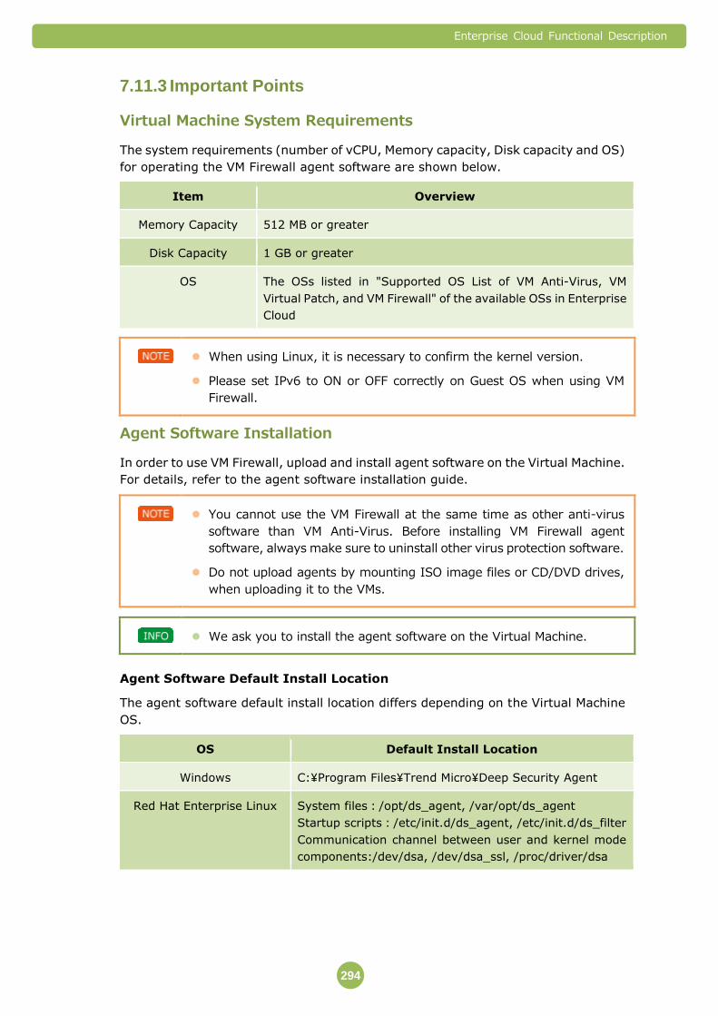
Enterprise Cloud Functional Description
294
Important Points 7.11.3
Virtual Machine System Requirements
The system requirements (number of vCPU, Memory capacity, Disk capacity and OS)
for operating the VM Firewall agent software are shown below.
Item Overview
Memory Capacity 512 MB or greater
Disk Capacity 1 GB or greater
OS The OSs listed in "Supported OS List of VM Anti-Virus, VM
Virtual Patch, and VM Firewall" of the available OSs in Enterprise
Cloud
When using Linux, it is necessary to confirm the kernel version.
Please set IPv6 to ON or OFF correctly on Guest OS when using VM
Firewall.
Agent Software Installation
In order to use VM Firewall, upload and install agent software on the Virtual Machine.
For details, refer to the agent software installation guide.
You cannot use the VM Firewall at the same time as other anti-virus
software than VM Anti-Virus. Before installing VM Firewall agent
software, always make sure to uninstall other virus protection software.
Do not upload agents by mounting ISO image files or CD/DVD drives,
when uploading it to the VMs.
We ask you to install the agent software on the Virtual Machine.
Agent Software Default Install Location
The agent software default install location differs depending on the Virtual Machine
OS.
OS Default Install Location
Windows C:¥Program Files¥Trend Micro¥Deep Security Agent
Red Hat Enterprise Linux System files:/opt/ds_agent, /var/opt/ds_agent
Startup scripts:/etc/init.d/ds_agent, /etc/init.d/ds_filter
Communication channel between user and kernel mode
components:/dev/dsa, /dev/dsa_ssl, /proc/driver/dsa

Enterprise Cloud Functional Description
295
You can change where it is installed. Also, the install location might
change due to agent software version updates, etc.
Communication with the Manager Administered by NTT
Communications
The Virtual Machine that uses VM Firewall must have communication with the
Manager administered by NTT Communications.
Please set the routing and the DNS name resolution setting.
Routing Settings
Please set the routing from the Virtual Machine to vFirewall/Integrated Network
Appliance using either of the following methods.
- Set the Virtual Machine default gateway to vFirewall/Integrated Network
Appliance
- Set vFirewall/Integrated Network Appliance as the static route gateway for
communication addressed to the Manager administered by NTT
Communications
If the Virtual Machine that uses VM Firewall is connected to a Server Segment that is
not directly connected to vFirewall/Integrated Network Appliance, additional Server
Segment is required to directly connect the vFirewall/Integrated Network Appliance
and the Virtual Machine.
DNS Name Resolution
In order to communicate with the Manager administered by NTT Communications,
name resolution for the manager is required. Please use the DNS server inside your
environment or the Virtual Machine hosts file to set name resolution for the Manager
administered by NTT Communications.
Restrictions
The rule names for the VM Firewall are set automatically. You cannot change the
settings.
Traffic below is blocked in any mode settings.
- TCP connections over 100,000
- UDP connections over 100,000
- Unusual traffic which is not based on RFC or suspected to be inaccurate.
No IP header
Source IP and Destination IP are the same
Text which is not available for URI
Using character “/” over 100
Using “../../” above route
And there will be blocking resulting from the shortage of compute resource.

Enterprise Cloud Functional Description
296
We ask you to assume responsibility for monitoring agent software (checking to
make sure it is activated at all times).
If you use a Private Catalog to create a template of the Virtual Machine image and
store it, please do it before installing the VM Firewall agent software.
If a template is created and saved from the Virtual Machine image of a Virtual
Machine where VM Firewall agent software is installed, or installation and
activation (registration to the Manager administered by NTT Communications) is
complete, when a Virtual Machine is created using that template, VM Firewall
can no longer be used with the Virtual Machine used for creating the template
and the newly-built Virtual Machine. The same applies when used for image
backup.
VM Firewall does not guarantee that the provided VM Firewall feature has integrity
or accuracy, or is suitable for your use.
The following information might be provided to the developers or distributors of the
devices making up the VM Firewall feature.
- Configuration information obtained from providing VM Firewall
- Configuration information obtained from controlling VM Firewall
We cannot guarantee recovery from failures that might occur due to incompatibility
between the VM Firewall feature and your environment, or failures that occur due to
your operations other than those specified by NTT Communications.
There may be times when the customer’s environment is affected by maintenance
services. An advance notice will be sent when there are possible effects to the
customer’s environment. This is not applied when we judge the maintenance work
urgent to continue service.
Enterprise Cloud Functional Description
297
7.12 Application Profiling
Application Profiling is a service that monitors the communication that
applications are using, and provides reports that make latent risks to the
applications (suspected information leaks and communication hypothesized to
be unrelated to work) visible.
Application Profiling is used via Service Interconnectivity. You need to
apply separately for Service Interconnectivity.
Available Features 7.12.1
You can use the following features with Application Profiling.
Feature Overview
Application Profiling Report A feature that monitors the communication that
applications are using, and provides reports that make
latent risks to the applications (suspected information
leaks and communication hypothesized to be unrelated to
work) visible.
Application Profiling Report 7.12.2
Application Profiling Report feature raises conceivable application communication
that supposedly have high risk from actual application usage, displays explanations
of hypothetical risks and advice for safely using the application.
Please check the following website for the applications that can be
monitored.
http://apps.paloaltonetworks.com/applipedia/
Reports are provided once a month.
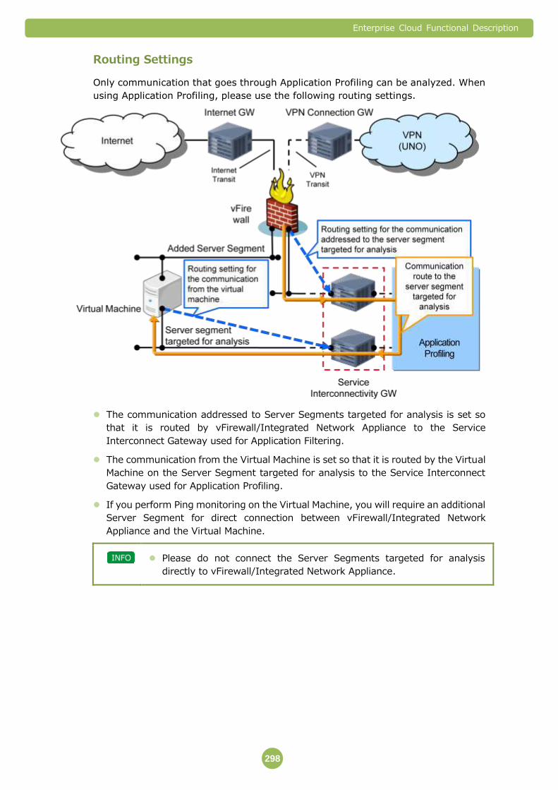
Enterprise Cloud Functional Description
298
Routing Settings
Only communication that goes through Application Profiling can be analyzed. When
using Application Profiling, please use the following routing settings.
The communication addressed to Server Segments targeted for analysis is set so
that it is routed by vFirewall/Integrated Network Appliance to the Service
Interconnect Gateway used for Application Filtering.
The communication from the Virtual Machine is set so that it is routed by the Virtual
Machine on the Server Segment targeted for analysis to the Service Interconnect
Gateway used for Application Profiling.
If you perform Ping monitoring on the Virtual Machine, you will require an additional
Server Segment for direct connection between vFirewall/Integrated Network
Appliance and the Virtual Machine.
Please do not connect the Server Segments targeted for analysis
directly to vFirewall/Integrated Network Appliance.

Enterprise Cloud Functional Description
299
Analysis Capacity
The traffic volume that can be analyzed by Application Profiling is shown below.
Item Performance Remarks
Per
service
Maximum
(5 services used)
Traffic Processing
Capacity
200 Mbps 1 Gbps The total value of uplink
and downlink.
Number of
concurrent
sessions
40,000 200,000 The number of sessions
that can be connected
simultaneously.
You can increase the traffic volume up to 1 Gbps, 200,000 sessions
(when 5 services used) by applying additional services. When using
more than 2 of service, please contact each NTT Communications
affiliate beforehand.
Important Points 7.12.3
Used IP Addresses
In order to connect the Service Interconnect Gateway with Application Profiling, you
must have two IP address blocks available. If the IP address block is already being
used, we might ask you to change it.
NTT Communications will manage the assigned IP address blocks, and assign IP
addresses to the devices that require them.
Restrictions
When the actual traffic volume exceeds the contracted traffic volume, the excess
traffic might be discarded.
Packets which break TCP/UDP/IP protocol rules or abnormal packets are discarded
as a standard function regardless of customer’s configuration.
(Examples)
- When the IP header is cut off in the middle
- When the Port number is 0 (zero)
- When the TCP flag combination is abnormal and others
If devices making up this feature are replaced due to malfunction etc., you will not
be able to check device logs or event reports from prior to the replacement via the
Security Web Portal. In addition, if the regular server and the standby server are
switched for a redundantly configured device and they are restored without
replacing the device, you cannot check the log or the event reports for the period
during which the switching occurred from the Security Web Portal.

Enterprise Cloud Functional Description
300
Application Profiling does not guarantee that the Application Profiling feature has
integrity or accuracy, or is suitable for your use. Furthermore, the suitability of the
application identification algorithms provided by the developers or distributors of the
devices making up the Application Profiling feature is not guaranteed.
The following information might be provided to the developers or distributors of the
devices making up the Application Profiling feature.
- Configuration information obtained from providing application profiling
- Information relating to Application Profiling processing
We cannot guarantee recovery from failures that might occur due to incompatibility
between Application Profiling and your environment, or failures that occur due to
your operations other than those specified by NTT Communications.
There may be times when the customer’s environment is affected by maintenance
services. An advance notice will be sent when there are possible effects to the
customer’s environment. This is not applied when we judge the maintenance work
urgent to continue service.

Enterprise Cloud Functional Description
301
7.13 Network Profiling
Network Profiling is a service that monitors the communication to the Virtual
Machine, and from the communication status provides reports that make
unknown threats and latent risks visible.
Network Profiling is used via Service Interconnectivity. You need to
apply separately for Service Interconnectivity.
Available Features 7.13.1
You can use the following features with Network Profiling.
Feature Overview
Network Profiling Report A feature that monitors communication to the Virtual
Machine and from the communication status provides
reports that make unknown threats and latent risks
visible.
Network Profiling Report 7.13.2
It monitors communication to the Virtual Machine, and provides reports that make
latent risks to the network visible, based on the correlation analyses on traffic logs
and threat logs (viruses and unauthorized access) performed by a security analyst.
Reports are provided once a month.

Enterprise Cloud Functional Description
302
Routing Settings
Only communication that goes through Network Profiling can be analyzed. When
using Network Profiling, please use the following routing settings.
The communication addressed to Server Segments targeted for analysis is set so
that it is routed by vFirewall/Integrated Network Appliance to the Service
Interconnect Gateway used for Network Profiling.
The communication from the Virtual Machine is set so that it is routed by the Virtual
Machine on the Server Segment targeted for analysis to the Service Interconnect
Gateway used for Network Profiling.
If you perform Ping monitoring on the Virtual Machine, you will require an additional
Server Segment for direct connection between vFirewall/Integrated Network
Appliance and the Virtual Machine.
Please do not connect the Server Segments targeted for analysis
directly to vFirewall/Integrated Network Appliance.

Enterprise Cloud Functional Description
303
Analysis Capacity
The traffic volume that can be analyzed by Network Profiling is shown below.
Item Performance Remarks
Per
service
Maximum
(5 services used)
Traffic Processing
Capacity
200 Mbps 1 Gbps The total value of uplink
and downlink.
Number of
concurrent
sessions
40,000 200,000 The number of sessions
that can be connected
simultaneously.
You can increase the traffic volume up to 1 Gbps, 200,000 sessions
(when 5 services used) by applying additional services. When using
more than 2 of service, please contact each NTT Communications
affiliate beforehand.
Important Points 7.13.3
Used IP Addresses
In order to connect the Service Interconnect Gateway with Network Profiling, you
must have two IP address blocks available. If the IP address block is already being
used, we might ask you to change it.
NTT Communications will manage the assigned IP address blocks, and assign IP
addresses to the devices that require them.
Restrictions
When the actual traffic volume exceeds the contracted traffic volume, the excess
traffic might be discarded.
Packets which break TCP/UDP/IP protocol rules or abnormal packets are discarded
as a standard function regardless of customer’s configuration.
(Examples)
- When the IP header is cut off in the middle
- When the Port number is 0 (zero)
- When the TCP flag combination is abnormal and others
If devices making up this feature are replaced due to malfunction etc., you will not
be able to check device logs or event reports from prior to the replacement via the
Security Web Portal. In addition, if the regular server and the standby server are
switched for a redundantly configured device and they are restored without
replacing the device, you cannot check the log or the event reports for the period
during which the switching occurred from the Security Web Portal.

Enterprise Cloud Functional Description
304
Network Profiling does not guarantee that the Network Profiling feature has integrity
or accuracy, or is suitable for your use. Furthermore, the suitability of the application,
virus and URL identification algorithms provided by the developers or distributors of
the devices making up the Network Profiling feature is not guaranteed.
The following information might be provided to the developers or distributors of the
devices making up the Network Profiling feature.
- Configuration information obtained from providing network profiling
- Information relating to Network Profiling processing
We cannot guarantee recovery from failures that might occur due to incompatibility
between Network Profiling and your environment, or failures that occur due to your
operations other than those specified by NTT Communications.
There may be times when the customer’s environment is affected by maintenance
services. An advance notice will be sent when there are possible effects to the
customer’s environment. This is not applied when we judge the maintenance work
urgent to continue service.
Enterprise Cloud Functional Description
305
7.14 RTMD Web
RTMD Web is a service that detects unauthorized malware intrusions, makes
unknown threats and latent risks visible, and reports them. Principally, it
provides a file analysis feature and a traffic analysis feature.
It not only performs signature-based analysis on the Customer traffic that
passes through vFirewall/Integrated Network Appliance by mirroring it, but also
it actually reproduces suspicious traffic in the RTMD Web virtual environment,
and analyzes malware dynamically.
You can use one RTMD Web for every Data Center.
The following specification is Japan DC version. For specification of
other Data Centers, please contact each NTT Communications affiliate.
Available Features 7.14.1
You can use the following features with RTMD Web.
Feature Overview
File Analysis A feature that inspects Web content that is sent and
received by Web access (HTTP communication), and
analyzes the content suspected of containing malware
and determines whether it is malware inside the virtual
environment.
Traffic Analysis A feature that detects access to fraudulent websites, and
Web access (HTTP communication) to C & C servers that
is executed by malware.
Report A feature that provides the assessment results of the file
analysis and traffic analysis as daily and monthly reports.
Analysis Capacity
The traffic volume that can be analyzed by RTMD Web is shown below.
Item Performance
(maximum
value)
Remarks
Traffic Processing Capacity 20 Mbps The total value of uplink and downlink.
File Analysis Feature 7.14.2
It mirrors customer traffic that passes through vFirewall/Integrated Network
Appliance, and detects suspicious communication that might trigger an attack, such
as downloads of obfuscated Java Script and executable files.

Enterprise Cloud Functional Description
306
The detected communication is actually reproduced in the RTMD Web virtual
environment. The content of changes generated inside the virtual environment
(such as file opening, closing, creating, changing and deleting, registry changes, and
API and addresses that are called) is recorded. Whether it is malware or not is
determined by those results.
The Virtual Environment that Analyzes Malware
By installing operating systems (OS), Web browsers and Microsoft Office in the
Malware Detection (Web) virtual environment, you can reproduce the attacks aimed
at the vulnerabilities of each application, and detect malware.
You can choose from the following operating systems (OS), Web browsers and
Microsoft Office versions to install in the virtual environment.
Item Software Options
Operating System (OS) Windows XP
Windows XP SP2, SP3
Windows 7
Windows 7 SP1
Windows 7 x64 SP1
Web Browser Internet Explorer 6 to 10
Firefox 3.5, 6.0, 17.0, 18.0, 23.0
Chrome 19.0, 25.0 (Windows XP, Windows 7)
Chrome 26.0 (Windows XP)
Microsoft Office Microsoft Office 2003
Microsoft Office 2007
Microsoft Office 2010
Traffic Analysis Feature 7.14.3
It mirrors customer traffic that passes through vFirewall/Integrated Network
Appliance, detects access to fraudulent websites and Web access (HTTP
communication) to C & C servers that is executed by malware.
Notification of detection status is made by Email etc.
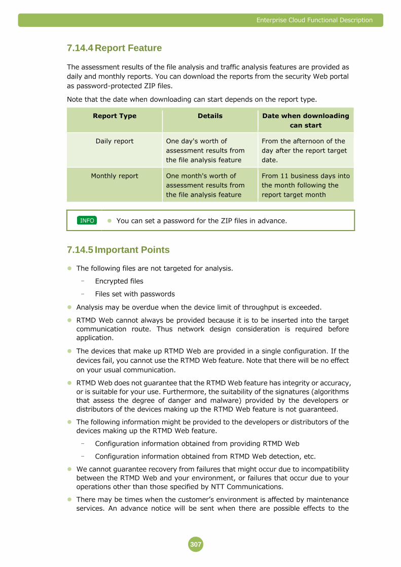
Enterprise Cloud Functional Description
307
Report Feature 7.14.4
The assessment results of the file analysis and traffic analysis features are provided as
daily and monthly reports. You can download the reports from the security Web portal
as password-protected ZIP files.
Note that the date when downloading can start depends on the report type.
Report Type Details Date when downloading
can start
Daily report One day's worth of
assessment results from
the file analysis feature
From the afternoon of the
day after the report target
date.
Monthly report One month's worth of
assessment results from
the file analysis feature
From 11 business days into
the month following the
report target month
You can set a password for the ZIP files in advance.
Important Points 7.14.5
The following files are not targeted for analysis.
- Encrypted files
- Files set with passwords
Analysis may be overdue when the device limit of throughput is exceeded.
RTMD Web cannot always be provided because it is to be inserted into the target
communication route. Thus network design consideration is required before
application.
The devices that make up RTMD Web are provided in a single configuration. If the
devices fail, you cannot use the RTMD Web feature. Note that there will be no effect
on your usual communication.
RTMD Web does not guarantee that the RTMD Web feature has integrity or accuracy,
or is suitable for your use. Furthermore, the suitability of the signatures (algorithms
that assess the degree of danger and malware) provided by the developers or
distributors of the devices making up the RTMD Web feature is not guaranteed.
The following information might be provided to the developers or distributors of the
devices making up the RTMD Web feature.
- Configuration information obtained from providing RTMD Web
- Configuration information obtained from RTMD Web detection, etc.
We cannot guarantee recovery from failures that might occur due to incompatibility
between the RTMD Web and your environment, or failures that occur due to your
operations other than those specified by NTT Communications.
There may be times when the customer’s environment is affected by maintenance
services. An advance notice will be sent when there are possible effects to the

Enterprise Cloud Functional Description
308
customer’s environment. This is not applied when we judge the maintenance work
urgent to continue service.
Enterprise Cloud Functional Description
309
7.15 RTMD Email
RTMD Email is a service that detects unauthorized malware intrusions via Email,
makes unknown threats and latent risks visible, and reports them. Principally, it
provides a file analysis feature.
It not only performs signature-based analysis on the Customer traffic that
passes through vFirewall/Integrated Network Appliance by mirroring it, but also
it actually reproduces suspicious traffic in the RTMD Email virtual environment,
and analyzes malware dynamically.
You can use one RTMD Email for every Data Center.
The following specification is Japan DC version. For specification of
other Data Centers, please contact each NTT Communications affiliate.
Available Features 7.15.1
You can use the following features with RTMD Email.
Feature Overview
File Analysis Feature A feature that inspects attachments to emails (SMTP
communication) and URL links and analyzes the content
suspected of containing malware and determines whether
it is malware inside the virtual environment.
File Analysis Feature 7.15.2
It mirrors the customer traffic that passes through the vFirewall/Integrated Network
Appliance, and detects suspicious files attached to email and URL links to fraudulent
sites.
The attachments are actually reproduced in the RTMD Email virtual environment.
The content of changes generated inside the virtual environment (such as file
opening, closing, creating, changing and deleting, registry changes, and API and
addresses that are called) is recorded. Whether it is malware or not is determined by
those results.
The Virtual Environment That Analyzes Malware
By installing operating systems (OS), Web browsers and Microsoft Office in the
Malware Detection (Email) virtual environment, you can reproduce the attacks
aimed at the vulnerabilities of each application, and detect malware.
You can choose from the following operating systems (OS), Web browsers and
Microsoft Office versions to install in the virtual environment.
Item Software Options
Operating System (OS) Windows XP

Enterprise Cloud Functional Description
310
Windows XP SP2, SP3
Windows 7
Windows 7 SP1
Windows 7 x64 SP1
Web Browser Internet Explorer 6 to 10
Firefox 3.5, 6.0, 17.0, 18.0, 23.0
Chrome 19.0, 25.0 (Windows XP, Windows)
Chrome 26.0 (Windows XP)
Microsoft Office Microsoft Office 2003
Microsoft Office 2007
Microsoft Office 2010
Report Feature
The malware assessment results and the results of detection of URL links to
fraudulent sites are provided in daily and monthly reports. You can download the
reports from the security Web portal as password-protected ZIP files.
Note that the date when downloading can start depends on the report type.
Report Type Details Date when downloading
can start
Daily report One day's worth of
assessment results from
the file analysis feature
From the afternoon of the
day after the report target
date.
Monthly report One month's worth of
assessment results from
the file analysis feature
From 11 business days into
the month following the
report target month
You can set a password for the ZIP files in advance.
Analysis Capacity
The traffic volume that can be analyzed by RTMD Email is shown below.
Item Performance (maximum value)
Number of emails 150,000 emails/day (6,250 emails per hour)
Number of email accounts 100 email accounts

Enterprise Cloud Functional Description
311
Important Points 7.15.3
The following files are not targeted for analysis.
- Encrypted files
- Files set with passwords
Analysis may be omitted when the device throughput limit is exceeded.
RTMD Email cannot always be provided because it is to be inserted into the target
communication route. Thus network design consideration before application is
required.
The devices that make up RTMD Email are provided in a single configuration. If the
devices fail, you cannot use the RTMD Email feature. Note that there will be no effect
on your usual communication.
RTMD Email does not guarantee that the RTMD Email feature has integrity or
accuracy, or is suitable for your use. Furthermore, the suitability of the signatures
(algorithms that assess the degree of danger and malware) provided by the
developers or distributors of the devices making up the RTMD Email feature is not
guaranteed.
The following information might be provided to the developers or distributors of the
devices making up the RTMD Email feature.
- Configuration information obtained from providing RTMD Email
- Configuration information obtained from RTMD Email detection, etc.
We cannot guarantee recovery from failures that might occur due to incompatibility
between the Real Time Malware Detection (Email) and your environment, or failures
that occur due to your operations other than those specified by NTT
Communications.
There may be times when the customer’s environment is affected by maintenance
services. An advance notice will be sent when there are possible effects to the
customer’s environment. This is not applied when we judge the maintenance work
urgent to continue service.
Enterprise Cloud Functional Description
312
8. Maintenance and Operation of the
Enterprise Cloud (Japan Contract)
At the NTT Communications Support Center, our highly skilled staff support
stable operations 24 hours/365 days.
8.1 Set of Materials Sent When You Start Using the Service
When you start using Enterprise Cloud, we will send you the following
documents.
All services Commencement information
Enterprise Cloud Functional Description
313
8.2 Customer Support
Support Center/Technical Help Desk 8.2.1
If you think there has been a failure or you do not understand how to configure the
system, contact the following center that is appropriate for your situation.
Inquiries regarding a failure Support Center
Technical inquiries Technical Help Desk
Please refer to the commencement information for contact details.
To use the Support Center or Technical Help Desk, you will need your
"customer number" that is provided when you start the service.
The scope of support is limited to inquiries relating to the contracted
service.
Ticket function
Ticket can be send by Customer Portal. The priority of the tickets will be judged
according to its content. Due to this, the response to the tickets may not be in order
when there are several tickets opened.
Incident Management
The following matters are treated as "incidents." All "incidents" are managed using a
ticket system and are assigned a "ticket number" in the Customer Portal.
Inquiries and requests notified to the Support Center or Technical Help Desk
If the matter is outside of the threshold of monitored items stipulated for each
service.The failure will be handled promptly as required.
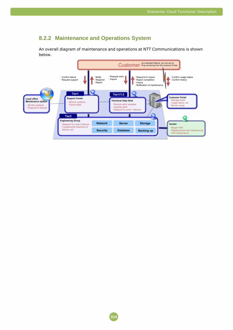
Enterprise Cloud Functional Description
314
Maintenance and Operations System 8.2.2
An overall diagram of maintenance and operations at NTT Communications is shown
below.
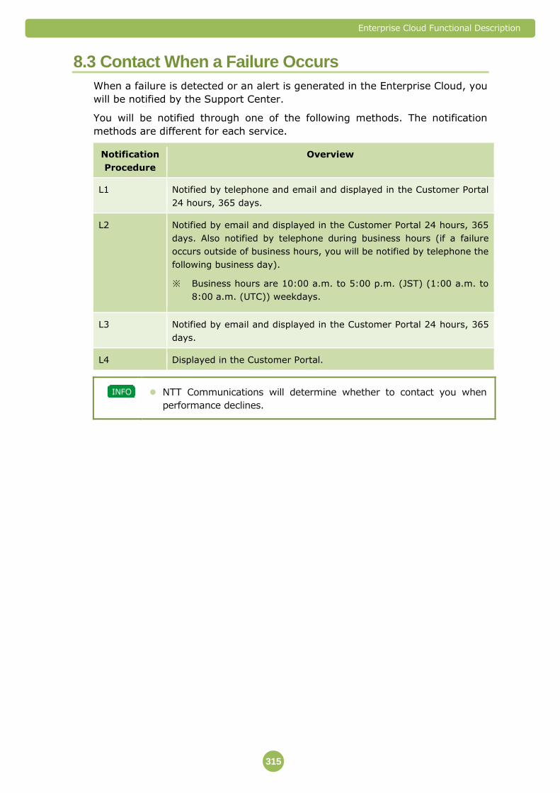
Enterprise Cloud Functional Description
315
8.3 Contact When a Failure Occurs
When a failure is detected or an alert is generated in the Enterprise Cloud, you
will be notified by the Support Center.
You will be notified through one of the following methods. The notification
methods are different for each service.
Notification
Procedure
Overview
L1 Notified by telephone and email and displayed in the Customer Portal
24 hours, 365 days.
L2 Notified by email and displayed in the Customer Portal 24 hours, 365
days. Also notified by telephone during business hours (if a failure
occurs outside of business hours, you will be notified by telephone the
following business day).
※ Business hours are 10:00 a.m. to 5:00 p.m. (JST) (1:00 a.m. to
8:00 a.m. (UTC)) weekdays.
L3 Notified by email and displayed in the Customer Portal 24 hours, 365
days.
L4 Displayed in the Customer Portal.
NTT Communications will determine whether to contact you when
performance declines.
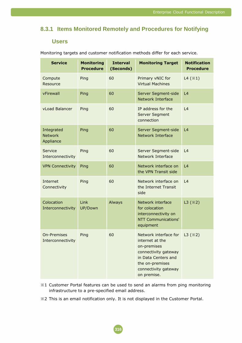
Enterprise Cloud Functional Description
316
Items Monitored Remotely and Procedures for Notifying 8.3.1
Users
Monitoring targets and customer notification methods differ for each service.
Service Monitoring
Procedure
Interval
(Seconds)
Monitoring Target Notification
Procedure
Compute
Resource
Ping 60 Primary vNIC for
Virtual Machines
L4 (※1)
vFirewall Ping 60 Server Segment-side
Network Interface
L4
vLoad Balancer Ping 60 IP address for the
Server Segment
connection
L4
Integrated
Network
Appliance
Ping 60 Server Segment-side
Network Interface
L4
Service
Interconnectivity
Ping 60 Server Segment-side
Network Interface
L4
VPN Connectivity Ping 60 Network interface on
the VPN Transit side
L4
Internet
Connectivity
Ping 60 Network interface on
the Internet Transit
side
L4
Colocation
Interconnectivity
Link
UP/Down
Always Network interface
for colocation
interconnectivity on
NTT Communications'
equipment
L3 (※2)
On-Premises
Interconnectivity
Ping 60 Network interface for
internet at the
on-premises
connectivity gateway
in Data Centers and
the on-premises
connectivity gateway
on premise.
L3 (※2)
※1 Customer Portal features can be used to send an alarms from ping monitoring
infrastructure to a pre-specified email address.
※2 This is an email notification only. It is not displayed in the Customer Portal.

Enterprise Cloud Functional Description
317
Remote Monitoring System 8.3.2
In the Enterprise Cloud, the NTT Communications monitoring infrastructure
monitors your contracted resources 24 hours, 365 days.
A diagram of the Enterprise Cloud monitoring is shown below.
Ping Monitoring for Compute Resource
Ping monitoring settings
If you set up monitoring notifications from the Customer Portal, you can perform
Ping monitoring on Compute Resource. Also, using the Customer Portal you can set
the alarm notification setting On/Off for each virtual server whenever the Virtual
Machine is powered on.
Ping monitoring contents
The primary vNICs of Virtual Machines created in a Compute Resource Pool are
pinged by the NTT Communications monitoring infrastructure every 60 seconds.
Enterprise Cloud Functional Description
318
If the ping fails three times in a row, a notification is sent to the registered email
address and displayed in the Customer Portal. If after that Ping succeeds even one
time, it is judged to be recovered, and the alarm notification is stopped.
Ping Monitoring of the vFirewall, vLoad Balancer, Service
Interconnectivity, VPN Connectivity, and Internet Connectivity
The network interface for monitored devices is pinged by the NTT Communications
monitoring infrastructure every 60 seconds.
If the ping fails three times in a row, a notification is displayed in the Customer Portal.
If after that Ping succeeds even one time, it is judged to be recovered, and the alarm
notification is stopped.
Ping Monitoring of On-Premises Interconnectivity
The monitored network interfaces are pinged by the NTT Communications
monitoring infrastructure every 60 seconds.
If the ping fails three times in a row, a notification is sent to the registered email
address. If after that Ping succeeds even one time, it is judged to be recovered, and
the alarm notification is stopped.
Monitoring Infrastructure Equipment
NTT Communications will monitor the infrastructure equipment making up the
Enterprise Cloud.
If a failure occurs on your dedicated infrastructure equipment or infrastructure
equipment for NTT Communications services that affect multiple customers, a
notification is sent to all customers that may be affected. A detailed report is not
necessarily included in the notification details.
If a partial failure occurs that does not affect your use of the system, we
may perform maintenance work without sending you a notification.
Enterprise Cloud Functional Description
319
8.4 Maintenance Information
In the Enterprise Cloud, we perform the maintenance necessary for continuous
use of your system, as required. The primary maintenance is described below.
Taking countermeasures against security vulnerability
Maintenance work and improvements on server and network devices
Advance Notice
If there are plans to perform maintenance, the Technical Help Desk will typically post
maintenance information on the Customer Portal two weeks in advance (unless the
work is urgent).
The maintenance information may include a request to borrow your
system.
If a partial failure occurs that does not affect your use of the system, we
may perform maintenance work without sending you a notification.
The switching behavior for devices in a redundant configuration at the
time of a failure of active device or the interface for the active device is
an automatic switch to a standby device. However, you may need to
manually switch from the standby device back to the active device
when the active device recovers.

Enterprise Cloud Functional Description
320
8.5 Limitations to Maintenance Operations
Support for Failures
When handling failures, we may have no choice but to restore your system to the
state it was in when you started using the Enterprise Cloud.
Ping Monitoring
You cannot instruct us to stop ping monitoring on your Virtual Machine.
Monitoring cannot be performed when the primary vNIC is connected to a Server
Segment that is not connected to vFirewall.
When adding a Server Segment, you can perform ping monitoring for each device
connected to this Server Segment by connecting this Server Segment to vFirewall.
Changing the settings on your Guest OS may cause pings to fail if response packets
from the primary vNIC are lost. This may be interpreted as a ping error.
Definition of Weekdays/Business Days
Weekdays/business days are based on Japan Standard Time (JST). They are Monday
to Friday, except for national holidays stipulated under the laws of Japan, and the
New Year period as stipulated by NTT Communications (December 29 to January 3).

Enterprise Cloud Functional Description
321
Index
A
Application Filtering .................................... 256
Application Profiling .................................... 296
B
Backup ............................................... 153, 232
C
Colocation Interconnectivity ........................ 188
Compute ..................................................... 56
Compute Resource ...................................... 56
Compute Resource (Dedicated Device) ......... 86
Contact When a Failure Occurs ................... 314
Customer Portal ........................................... 39
Customer Support...................................... 312
Customer System Environment ................. 193
D
Database License ....................................... 113
Database License (MS SQL) ........................ 113
Detection and blocking of attack traffic . 239, 287
Detection and blocking of unauthorized access239
E
Email-Anti-Virus ......................................... 243
Enterprise Cloud Customer Portal .................. 39
Equipment Environment ............................... 18
Example Usage Model .................................. 33
External Storage Feature ............................ 232
F
Firewall ...................................... 199, 260, 292
G
Global Data Backup .................................... 232
Global File Storage ..................................... 232
Global IP Address ...................................... 169
Global Standard Menu .................................. 14
Guest OS Customization ........................ 73, 75
I
Image Backup ........................................... 153
Internet Connectivity .................................. 169
IPS/IDS ..................................................... 239
Items Monitored Remotely and Procedures for
Notifying Users ....................................... 315
L
Load Balancer ............................................ 207
Load Distribution ........................................ 207
Local Option Menu ....................................... 31
M
Maintenance and Operation (Japan Contract)311
Maintenance and Operations ...................... 319
Maintenance and Operations System .......... 313
Maintenance Information ............................ 318
Malware Detection (Email) .......................... 308
Malware Detection (Web) ........................... 304
Microsoft SAL ............................................. 146
Microsoft SQL Server License ...................... 113
N
NAT/NAPT Feature .................................... 199
Network Features ...................................... 169
Enterprise Cloud Functional Description
322
Network profiling ....................................... 300
O
On-Premises Interconnectivity .................... 193
OS License ................................................ 107
Overview ..................................................... 10
P
Packet Filtering Feature ............................. 199
Virtual ....................................................... 287
Portal Site .................................................... 39
Private Catalog ............................................ 98
R
RDS SAL.................................................... 146
Real Time Malware Detection (Email) .......... 308
Real Time Malware Detection (Web) ........... 304
Red Hat Enterprise Linux ........................... 107
Remote Monitoring System ........................ 316
Routing Feature ........................................ 199
S
Security Features ....................................... 239
Security Web Portal ...................................... 52
Server Segment ......................................... 178
Service Interconnectivity ............................ 185
Service Management .................................... 39
Set of Materials Sent When You Start Using the
Service ................................................... 311
Support Center .......................................... 312
T
Technical Help Desk ................................... 312
Template .................................................... 98
Terms ......................................................... 35
V
vFirewall .................................................... 199
Virtual Machine ........................................... 98
vLoad Balancer .......................................... 207
VM-Anti-Virus ............................................ 279
VM-Firewall ............................................... 292
VPN Connectivity ....................................... 173
W
WAF .......................................................... 260
Web Application Firewall ............................. 260
Web-Anti-Virus .......................................... 247
Windows Server ........................................ 107
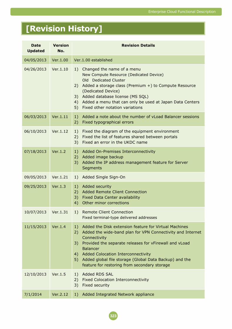
Enterprise Cloud Functional Description
323
[Revision History]
Date
Updated
Version
No.
Revision Details
04/05/2013 Ver.1.00 Ver.1.00 established
04/26/2013 Ver.1.10 1) Changed the name of a menu
New Compute Resource (Dedicated Device)
Old Dedicated Cluster
2) Added a storage class (Premium +) to Compute Resource
(Dedicated Device)
3) Added database license (MS SQL)
4) Added a menu that can only be used at Japan Data Centers
5) Fixed other notation variations
06/03/2013 Ver.1.11 1) Added a note about the number of vLoad Balancer sessions
2) Fixed typographical errors
06/10/2013 Ver.1.12 1) Fixed the diagram of the equipment environment
2) Fixed the list of features shared between portals
3) Fixed an error in the UKDC name
07/18/2013 Ver.1.2 1) Added On-Premises Interconnectivity
2) Added image backup
3) Added the IP address management feature for Server
Segments
09/05/2013 Ver.1.21 1) Added Single Sign-On
09/25/2013 Ver.1.3 1) Added security
2) Added Remote Client Connection
3) Fixed Data Center availability
4) Other minor corrections
10/07/2013 Ver.1.31 1) Remote Client Connection
Fixed terminal-type delivered addresses
11/15/2013 Ver.1.4 1) Added the Disk extension feature for Virtual Machines
2) Added the wide-band plan for VPN Connectivity and Internet
Connectivity
3) Provided the separate releases for vFirewall and vLoad
Balancer
4) Added Colocation Interconnectivity
5) Added global file storage (Global Data Backup) and the
feature for restoring from secondary storage
12/10/2013 Ver.1.5 1) Added RDS SAL
2) Fixed Colocation Interconnectivity
3) Fixed security
7/1/2014 Ver.2.12 1) Added Integrated Network appliance

Enterprise Cloud Functional Description
324
Date
Updated
Version
No.
Revision Details
2) Added Colocation Interconnectivity
3) Added Guaranteed Compute
4) Added Dedicated Compute (S/M/L)
5) Updated Security Option Menu
6) Updated the table “Service Provided by Each Data Center”
8/1/2014 Ver.2.13 1) Delete Important Point about OS License activation in case of
using Integrated Network Appliance.
2) Updated service menu list in each Data Center.
3) Updated Security Service.
4) Delete Important Point about contract in Colocation
Connectivity.
8/20/2014 Ver.2.14 1) Updated OS License (Windows Server 2012)
2) Updated important point in Internet Connectivity. (The DNS
resolver is not offered with this service.)
9/1/2014 Ver.2.15 1) Updated Image Backup
2) Added File Backup
3) Updated service menu list in each Data Center.
4) Updated IPsec parameters in Integrated Network Appliance
5) Updated Security
9/5/2014 Ver.2.16 1) Updated service menu list in each Data Center.
2) Updated Security
9/12/2014 Ver.2.17 1) Added OS License (Windows Server 2012) in US,MY
2) Updated File Backup
10/1/2014 Ver.2.18 1) Updated service menu list in each Data Center.
2) Updated Japanese local service menu.
3) Updated Customer Portal function.
4) Updated VPN Connectivity and Server Segment.
5) Updated Colocation Connectivity.
11/12/2014 Ver.2.19 1) Updated service menu list in each Data Center
INA (US/UK/Kansai), Security Option
2) Updated Image Backup
3) Updated Server Segment
4) Updated Database License
OS template version for Windows Server 2012
5) Updated Security Option (URL Filtering)
6) Updated Ticket Function
12/9/2014 Ver2.20 1) Updated the All Service Specifications related to Germany DC
as it is now aligned with other Data Centers
2) Revised Compute Resource (Dedicated)
Deleted the description regarding the Customer Portal
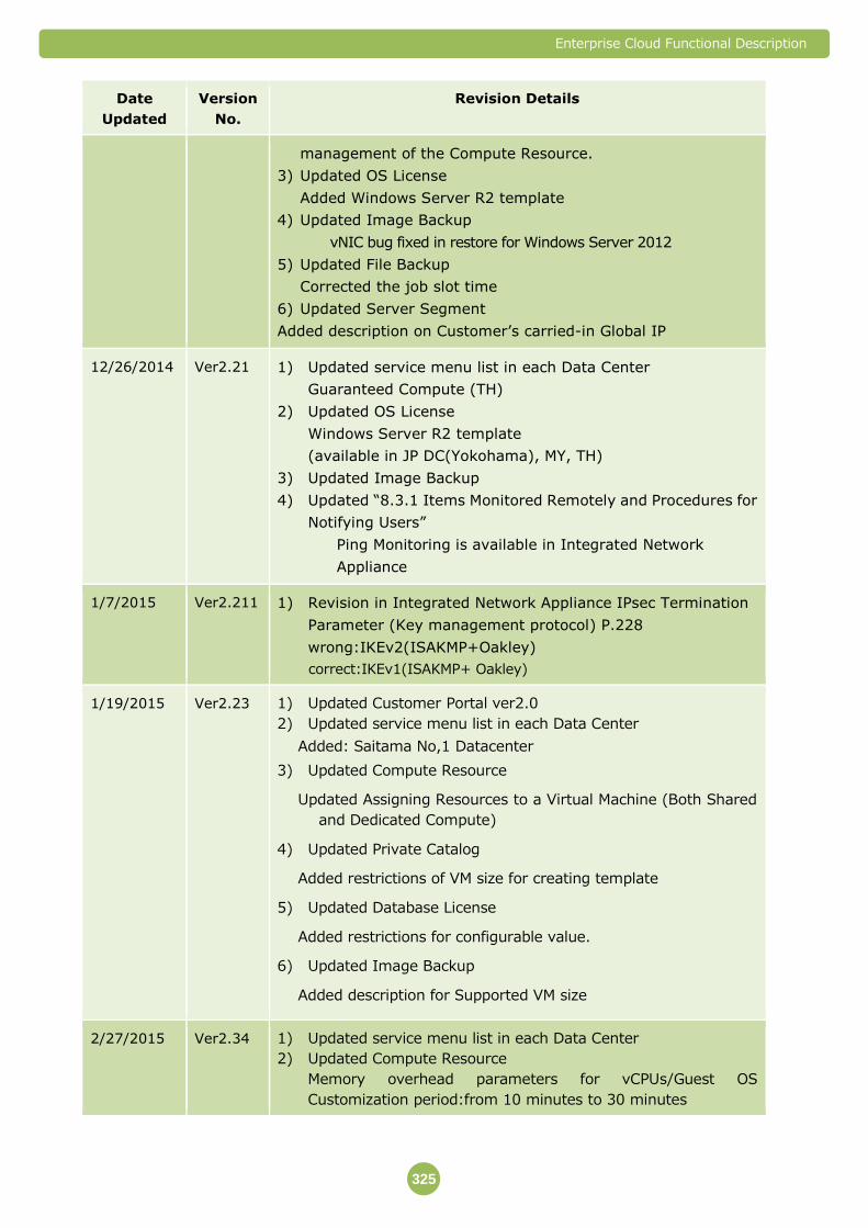
Enterprise Cloud Functional Description
325
Date
Updated
Version
No.
Revision Details
management of the Compute Resource.
3) Updated OS License
Added Windows Server R2 template
4) Updated Image Backup
vNIC bug fixed in restore for Windows Server 2012
5) Updated File Backup
Corrected the job slot time
6) Updated Server Segment
Added description on Customer’s carried-in Global IP
12/26/2014 Ver2.21 1) Updated service menu list in each Data Center
Guaranteed Compute (TH)
2) Updated OS License
Windows Server R2 template
(available in JP DC(Yokohama), MY, TH)
3) Updated Image Backup
4) Updated “8.3.1 Items Monitored Remotely and Procedures for
Notifying Users”
Ping Monitoring is available in Integrated Network
Appliance
1/7/2015 Ver2.211 1) Revision in Integrated Network Appliance IPsec Termination
Parameter (Key management protocol) P.228
wrong:IKEv2(ISAKMP+Oakley)
correct:IKEv1(ISAKMP+ Oakley)
1/19/2015 Ver2.23 1) Updated Customer Portal ver2.0
2) Updated service menu list in each Data Center
Added: Saitama No,1 Datacenter
3) Updated Compute Resource
Updated Assigning Resources to a Virtual Machine (Both Shared
and Dedicated Compute)
4) Updated Private Catalog
Added restrictions of VM size for creating template
5) Updated Database License
Added restrictions for configurable value.
6) Updated Image Backup
Added description for Supported VM size
2/27/2015 Ver2.34 1) Updated service menu list in each Data Center
2) Updated Compute Resource
Memory overhead parameters for vCPUs/Guest OS
Customization period:from 10 minutes to 30 minutes
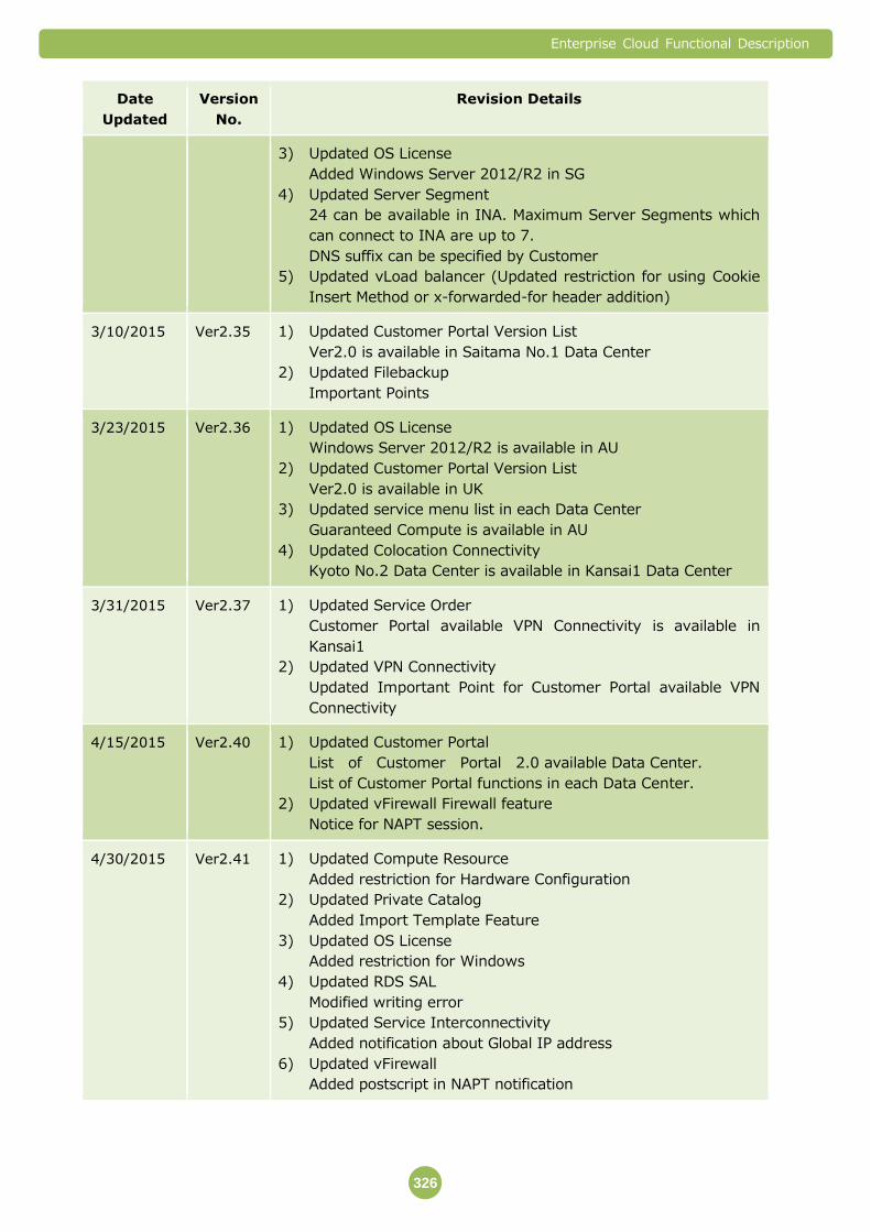
Enterprise Cloud Functional Description
326
Date
Updated
Version
No.
Revision Details
3) Updated OS License
Added Windows Server 2012/R2 in SG
4) Updated Server Segment
24 can be available in INA. Maximum Server Segments which
can connect to INA are up to 7.
DNS suffix can be specified by Customer
5) Updated vLoad balancer (Updated restriction for using Cookie
Insert Method or x-forwarded-for header addition)
3/10/2015 Ver2.35 1) Updated Customer Portal Version List
Ver2.0 is available in Saitama No.1 Data Center
2) Updated Filebackup
Important Points
3/23/2015 Ver2.36 1) Updated OS License
Windows Server 2012/R2 is available in AU
2) Updated Customer Portal Version List
Ver2.0 is available in UK
3) Updated service menu list in each Data Center
Guaranteed Compute is available in AU
4) Updated Colocation Connectivity
Kyoto No.2 Data Center is available in Kansai1 Data Center
3/31/2015 Ver2.37 1) Updated Service Order
Customer Portal available VPN Connectivity is available in
Kansai1
2) Updated VPN Connectivity
Updated Important Point for Customer Portal available VPN
Connectivity
4/15/2015 Ver2.40 1) Updated Customer Portal
List of Customer Portal 2.0 available Data Center.
List of Customer Portal functions in each Data Center.
2) Updated vFirewall Firewall feature
Notice for NAPT session.
4/30/2015 Ver2.41 1) Updated Compute Resource
Added restriction for Hardware Configuration
2) Updated Private Catalog
Added Import Template Feature
3) Updated OS License
Added restriction for Windows
4) Updated RDS SAL
Modified writing error
5) Updated Service Interconnectivity
Added notification about Global IP address
6) Updated vFirewall
Added postscript in NAPT notification
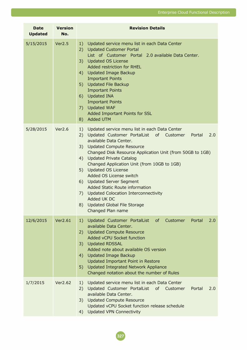
Enterprise Cloud Functional Description
327
Date
Updated
Version
No.
Revision Details
5/15/2015 Ver2.5 1) Updated service menu list in each Data Center
2) Updated Customer Portal
List of Customer Portal 2.0 available Data Center.
3) Updated OS License
Added restriction for RHEL
4) Updated Image Backup
Important Points
5) Updated File Backup
Important Points
6) Updated INA
Important Points
7) Updated WAF
Added Important Points for SSL
8) Added UTM
5/28/2015 Ver2.6 1) Updated service menu list in each Data Center
2) Updated Customer PortalList of Customer Portal 2.0
available Data Center.
3) Updated Compute Resource
Changed Disk Resource Application Unit (from 50GB to 1GB)
4) Updated Private Catalog
Changed Application Unit (from 10GB to 1GB)
5) Updated OS License
Added OS License switch
6) Updated Server Segment
Added Static Route information
7) Updated Colocation Interconnectivity
Added UK DC
8) Updated Global File Storage
Changed Plan name
12/6/2015 Ver2.61 1) Updated Customer PortalList of Customer Portal 2.0
available Data Center.
2) Updated Compute Resource
Added vCPU Socket function
3) Updated RDSSAL
Added note about available OS version
4) Updated Image Backup
Updated Important Point in Restore
5) Updated Integrated Network Appliance
Changed notation about the number of Rules
1/7/2015 Ver2.62 1) Updated service menu list in each Data Center
2) Updated Customer PortalList of Customer Portal 2.0
available Data Center.
3) Updated Compute Resource
Updated vCPU Socket function release schedule
4) Updated VPN Connectivity
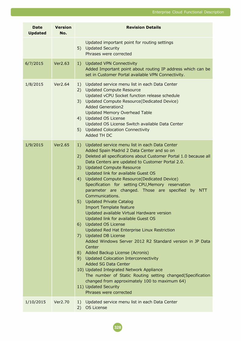
Enterprise Cloud Functional Description
328
Date
Updated
Version
No.
Revision Details
Updated important point for routing settings
5) Updated Security
Phrases were corrected
6/7/2015 Ver2.63 1) Updated VPN Connectivity
Added Important point about routing IP address which can be
set in Customer Portal available VPN Connectivity.
1/8/2015 Ver2.64 1) Updated service menu list in each Data Center
2) Updated Compute Resource
Updated vCPU Socket function release schedule
3) Updated Compute Resource(Dedicated Device)
Added Generation2
Updated Memory Overhead Table
4) Updated OS License
Updated OS License Switch available Data Center
5) Updated Colocation Connectivity
Added TH DC
1/9/2015 Ver2.65 1) Updated service menu list in each Data Center
Added Spain Madrid 2 Data Center and so on
2) Deleted all specifications about Customer Portal 1.0 because all
Data Centers are updated to Customer Portal 2.0.
3) Updated Compute Resource
Updated link for available Guest OS
4) Updated Compute Resource(Dedicated Device)
Specification for setting CPU,Memory reservation
parameter are changed. Those are specified by NTT
Communications.
5) Updated Private Catalog
Import Template feature
Updated available Virtual Hardware version
Updated link for available Guest OS
6) Updated OS License
Updated Red Hat Enterprise Linux Restriction
7) Updated DB License
Added Windows Server 2012 R2 Standard version in JP Data
Center
8) Added Backup License (Acronis)
9) Updated Colocation Interconnectivity
Added SG Data Center
10) Updated Integrated Network Appliance
The number of Static Routing setting changed(Specification
changed from approximately 100 to maximum 64)
11) Updated Security
Phrases were corrected
1/10/2015 Ver2.70 1) Updated service menu list in each Data Center
2) OS License

Enterprise Cloud Functional Description
329
Date
Updated
Version
No.
Revision Details
Updated Red Hat Enterprise Linux Restrictions
3) Database License(MS-SQL)
Updated Important Point about the number of vCPUs
4) Updated vFirewall
Added log dedicated portal
5) Updated UTM
Added restriction in non-Japanese Data Centers
6) Added Web Security(WAF)
7) Updated Ticket Function
1/11/2015 Ver2.71 1) Updated service menu list in each Data Center
2) Service Order
Added note about UTM and Web Security(WAF)
3) Compute Resource
Added memo about the number of vCPU in virtual hardware
version
4) Compute Resource(Dedicated Device)
Added memo about the number of vCPU and amount of
memory in virtual hardware version
5) vLoad Balancer
Added note about specification of Header Addition
Feature(x-forwarded-for)
1/12/2015 Ver2.72 1) Updated service menu list in each Data Center
2) Updated Compute Resource
Deleted memo about the number of minimum Compute Resorce
Pool contract restriction
3) Updated Private Catalog
Deleted attention about importing CentOS template
4) Updated OS License
Updated Red Hat Enterprise Linux Restrictions
5) Updated Security
Added attention about maintenance and Used IP address
1/1/2016 Ver2.73 1) Updated service menu list in each Data Center
2) Updated Compute Resource(Dedicated Device)
Added Generation3 Small
3) Updated Secrity
Added memo when using more than 2 of service (IPS/IDS,
Email Anti-Virus, Web Anti-Virus, URL Filtering, Application
Filtering, Application Profiling, Network Profiling)
Updated Important Point about IP Address assign and
Contract(UTM)
Updated Important Point about control rule(VM Firewall)
15/1/2016 Ver2.74 1) Updated Image Backup
Added Important Points when Virtual Server will be deleted
2) Updated vLoad Balancer
Updated note about specification of Header Addition

Enterprise Cloud Functional Description
330
Date
Updated
Version
No.
Revision Details
Feature(x-forwarded-for). The specification become to be
applied to all vLoad Balancer users in Japanese Data Center.
1/2/2016 Ver2.8 1) Updated service menu list in each Data Center
2) Updated Service Order
Acronis License is available by Customer Portal
3) Updated availability of Customer Portal functions in each Data
Center
4) Added Kansa1 Data Center Annex(Kansai1a)
5) Compute Resouce
Added Non-duplicable IP Address Bands in Kansai1a
6) OS License
It's omitted version number below the decimal point in Red Hat
Enterprise Linux. It is possible to check it in Cutomer Portal
Updated Important Point about yum upgrade
7) DB License(MS-SQL)
Deleted note for available Widows OS License in Data Center.
Windows Server 2012/R2 will be provided all Data Centers.
8) Added DB License(Oracle SE One)
9) Added DB License(Oracle EE)
10) Image Backup
Added Supported OS(Red Hat Enterprise Linux6.5)
11) VPN Connectivity
Added Non-duplicable IP Address Bands in Kansai1a
12) Server Segment
Updated Important Points
Added Non-duplicable IP Address Bands in Kansai1a
Static Route information
In case of over 64 Virtual Machine will be used
13) Colocation Interconnectivity
Added available Data Center(ES,AU)
14) Items Monitored Remotely and Procedures for Notifying Users
Added Integrated Network Appliance
Deleted Global File Storage
1/3/2016 Ver2.81 1) Updated service menu list in each Data Center
2) Enterprise Cloud Customer Poral
Added Each Type of Permissions
3) Compute Resource
Updated vCPU Socket function release schedule
4) vLoad Balancer
Word correction
5) UTM
Updated Important Points
6) Web Securty (WAF)
Updated Important Points
1/3/2016 Ver2.82 1) Purpose of This Document/How to Use This Document
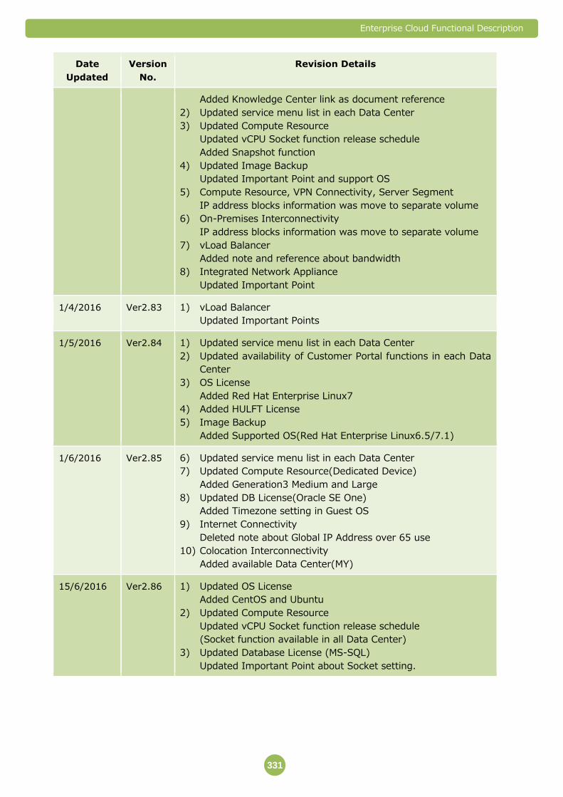
Enterprise Cloud Functional Description
331
Date
Updated
Version
No.
Revision Details
Added Knowledge Center link as document reference
2) Updated service menu list in each Data Center
3) Updated Compute Resource
Updated vCPU Socket function release schedule
Added Snapshot function
4) Updated Image Backup
Updated Important Point and support OS
5) Compute Resource, VPN Connectivity, Server Segment
IP address blocks information was move to separate volume
6) On-Premises Interconnectivity
IP address blocks information was move to separate volume
7) vLoad Balancer
Added note and reference about bandwidth
8) Integrated Network Appliance
Updated Important Point
1/4/2016 Ver2.83 1) vLoad Balancer
Updated Important Points
1/5/2016 Ver2.84 1) Updated service menu list in each Data Center
2) Updated availability of Customer Portal functions in each Data
Center
3) OS License
Added Red Hat Enterprise Linux7
4) Added HULFT License
5) Image Backup
Added Supported OS(Red Hat Enterprise Linux6.5/7.1)
1/6/2016 Ver2.85 6) Updated service menu list in each Data Center
7) Updated Compute Resource(Dedicated Device)
Added Generation3 Medium and Large
8) Updated DB License(Oracle SE One)
Added Timezone setting in Guest OS
9) Internet Connectivity
Deleted note about Global IP Address over 65 use
10) Colocation Interconnectivity
Added available Data Center(MY)
15/6/2016 Ver2.86 1) Updated OS License
Added CentOS and Ubuntu
2) Updated Compute Resource
Updated vCPU Socket function release schedule
(Socket function available in all Data Center)
3) Updated Database License (MS-SQL)
Updated Important Point about Socket setting.


![[1]Oracle® Enterprise Manager Cloud Control Introduction ... · Chapter 1, "Overview of Oracle Enterprise Manager Cloud Control 13c" Presents the Enterprise Manager Cloud Control](https://img.pdfslide.us/doc/110x75/5ec8dc9214ea260bfd794e63/1oracle-enterprise-manager-cloud-control-introduction-chapter-1-overview.jpg)