Embed Size (px)
Citation preview
LO W I M PA C T D E V E LO P M E N T P L A N N I N G A N D D E S I G N FA C T S H E E T
DESIGN
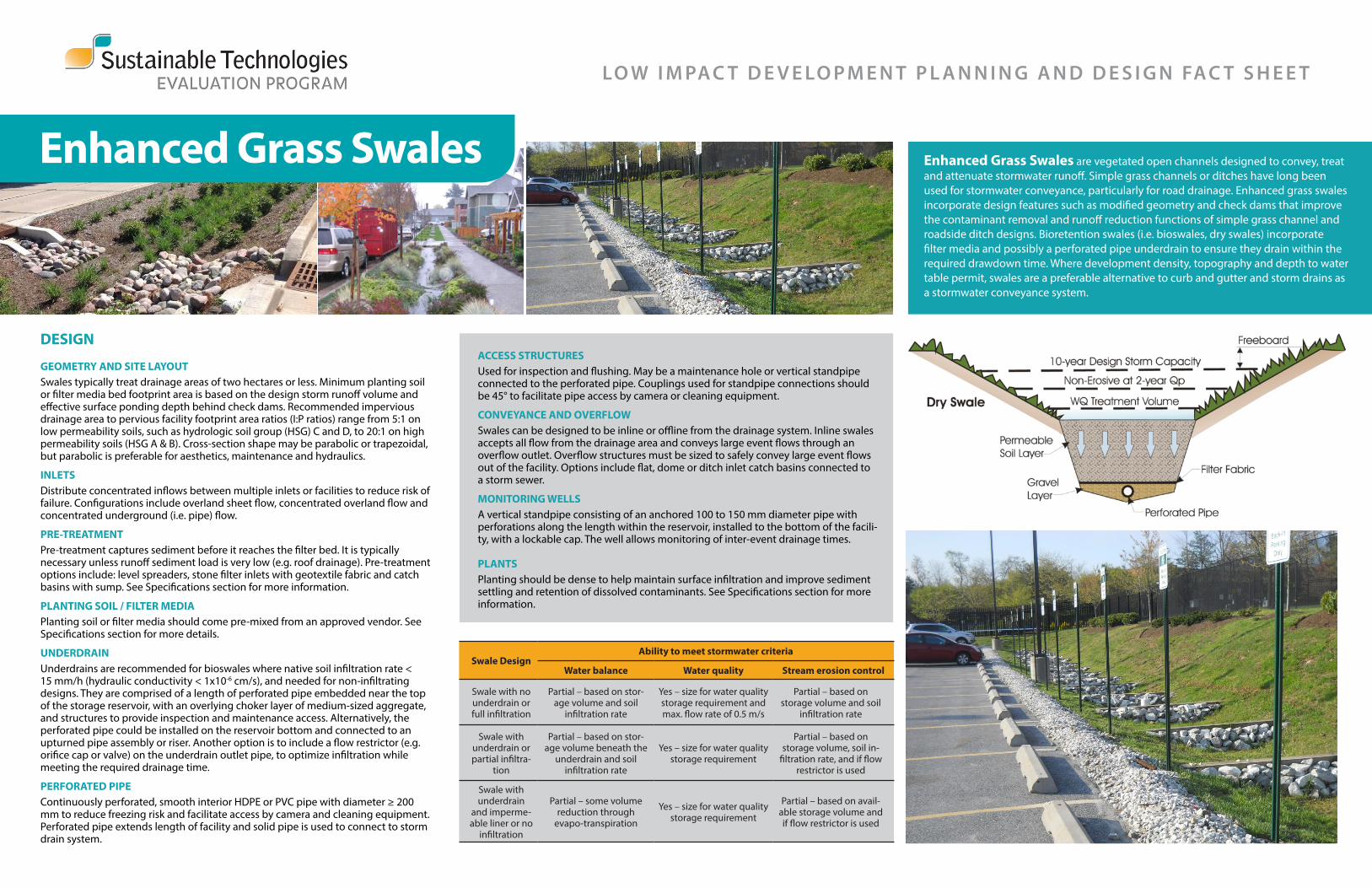
GEOMETRY AND SITE LAYOUTSwales typically treat drainage areas of two hectares or less. Minimum planting soil or filter media bed footprint area is based on the design storm runoff volume and effective surface ponding depth behind check dams. Recommended impervious drainage area to pervious facility footprint area ratios (I:P ratios) range from 5:1 on low permeability soils, such as hydrologic soil group (HSG) C and D, to 20:1 on high permeability soils (HSG A & B). Cross-section shape may be parabolic or trapezoidal, but parabolic is preferable for aesthetics, maintenance and hydraulics.
INLETSDistribute concentrated inflows between multiple inlets or facilities to reduce risk of failure. Configurations include overland sheet flow, concentrated overland flow and concentrated underground (i.e. pipe) flow.
PRE-TREATMENT Pre-treatment captures sediment before it reaches the filter bed. It is typically necessary unless runoff sediment load is very low (e.g. roof drainage). Pre-treatment options include: level spreaders, stone filter inlets with geotextile fabric and catch basins with sump. See Specifications section for more information.
PLANTING SOIL / FILTER MEDIAPlanting soil or filter media should come pre-mixed from an approved vendor. See Specifications section for more details.
UNDERDRAINUnderdrains are recommended for bioswales where native soil infiltration rate < 15 mm/h (hydraulic conductivity < 1x10⁻⁶ cm/s), and needed for non-infiltrating designs. They are comprised of a length of perforated pipe embedded near the top of the storage reservoir, with an overlying choker layer of medium-sized aggregate, and structures to provide inspection and maintenance access. Alternatively, the perforated pipe could be installed on the reservoir bottom and connected to an upturned pipe assembly or riser. Another option is to include a flow restrictor (e.g. orifice cap or valve) on the underdrain outlet pipe, to optimize infiltration while meeting the required drainage time.
PERFORATED PIPEContinuously perforated, smooth interior HDPE or PVC pipe with diameter ≥ 200 mm to reduce freezing risk and facilitate access by camera and cleaning equipment. Perforated pipe extends length of facility and solid pipe is used to connect to storm drain system.
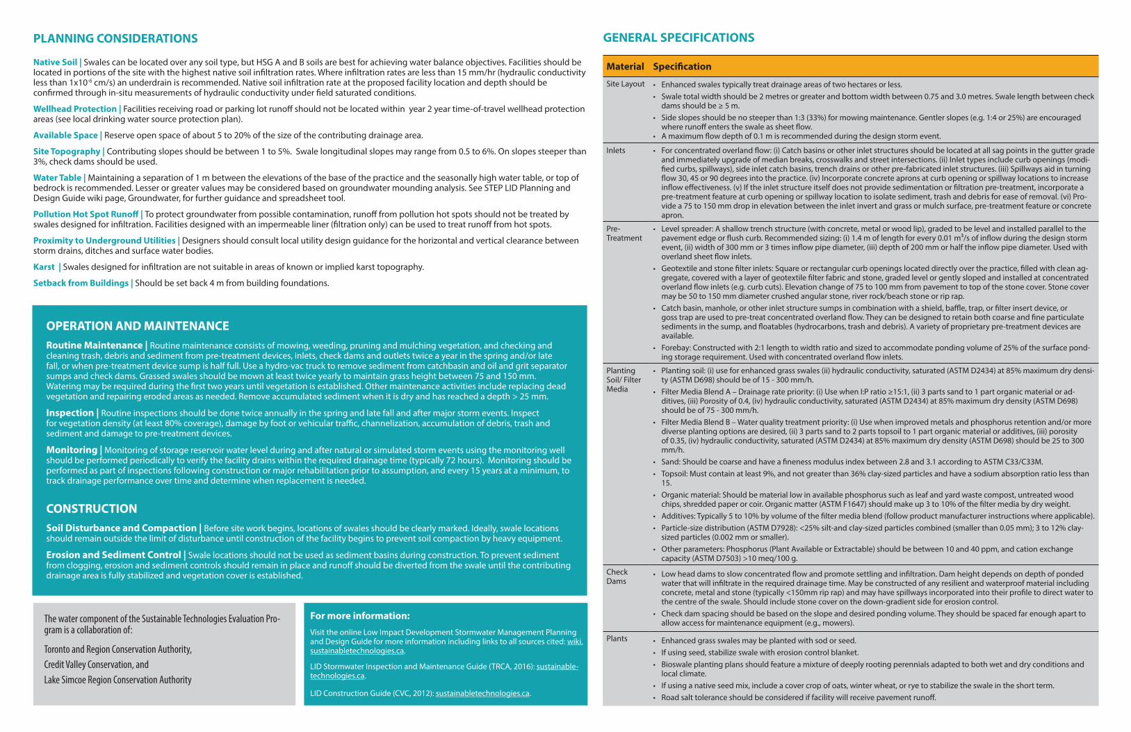
Enhanced Grass Swales Enhanced Grass Swales are vegetated open channels designed to convey, treat and attenuate stormwater runoff. Simple grass channels or ditches have long been used for stormwater conveyance, particularly for road drainage. Enhanced grass swales incorporate design features such as modified geometry and check dams that improve the contaminant removal and runoff reduction functions of simple grass channel and roadside ditch designs. Bioretention swales (i.e. bioswales, dry swales) incorporate filter media and possibly a perforated pipe underdrain to ensure they drain within the required drawdown time. Where development density, topography and depth to water table permit, swales are a preferable alternative to curb and gutter and storm drains as a stormwater conveyance system.
ACCESS STRUCTURESUsed for inspection and flushing. May be a maintenance hole or vertical standpipe connected to the perforated pipe. Couplings used for standpipe connections should be 45° to facilitate pipe access by camera or cleaning equipment.
CONVEYANCE AND OVERFLOWSwales can be designed to be inline or offline from the drainage system. Inline swales accepts all flow from the drainage area and conveys large event flows through an overflow outlet. Overflow structures must be sized to safely convey large event flows out of the facility. Options include flat, dome or ditch inlet catch basins connected to a storm sewer.
MONITORING WELLSA vertical standpipe consisting of an anchored 100 to 150 mm diameter pipe with perforations along the length within the reservoir, installed to the bottom of the facili-ty, with a lockable cap. The well allows monitoring of inter-event drainage times.
PLANTSPlanting should be dense to help maintain surface infiltration and improve sediment settling and retention of dissolved contaminants. See Specifications section for more information.
Swale DesignAbility to meet stormwater criteria
Water balance Water quality Stream erosion control
Swale with no underdrain or full infiltration
Partial – based on stor-age volume and soil
infiltration rate
Yes – size for water quality storage requirement and max. flow rate of 0.5 m/s
Partial – based on storage volume and soil
infiltration rate
Swale with underdrain or partial infiltra-
tion
Partial – based on stor-age volume beneath the
underdrain and soil infiltration rate
Yes – size for water quality storage requirement
Partial – based on storage volume, soil in-
filtration rate, and if flow restrictor is used
Swale with underdrain
and imperme-able liner or no
infiltration
Partial – some volume reduction through
evapo-transpiration
Yes – size for water quality storage requirement
Partial – based on avail-able storage volume and if flow restrictor is used
PLANNING CONSIDERATIONS
Native Soil | Swales can be located over any soil type, but HSG A and B soils are best for achieving water balance objectives. Facilities should be located in portions of the site with the highest native soil infiltration rates. Where infiltration rates are less than 15 mm/hr (hydraulic conductivity less than 1x10⁻⁶ cm/s) an underdrain is recommended. Native soil infiltration rate at the proposed facility location and depth should be confirmed through in-situ measurements of hydraulic conductivity under field saturated conditions.
Wellhead Protection | Facilities receiving road or parking lot runoff should not be located within year 2 year time-of-travel wellhead protection areas (see local drinking water source protection plan).
Available Space | Reserve open space of about 5 to 20% of the size of the contributing drainage area.
Site Topography | Contributing slopes should be between 1 to 5%. Swale longitudinal slopes may range from 0.5 to 6%. On slopes steeper than 3%, check dams should be used.
Water Table | Maintaining a separation of 1 m between the elevations of the base of the practice and the seasonally high water table, or top of bedrock is recommended. Lesser or greater values may be considered based on groundwater mounding analysis. See STEP LID Planning and Design Guide wiki page, Groundwater, for further guidance and spreadsheet tool.
Pollution Hot Spot Runoff | To protect groundwater from possible contamination, runoff from pollution hot spots should not be treated by swales designed for infiltration. Facilities designed with an impermeable liner (filtration only) can be used to treat runoff from hot spots.
Proximity to Underground Utilities | Designers should consult local utility design guidance for the horizontal and vertical clearance between storm drains, ditches and surface water bodies.
Karst | Swales designed for infiltration are not suitable in areas of known or implied karst topography.
Setback from Buildings | Should be set back 4 m from building foundations.
OPERATION AND MAINTENANCERoutine Maintenance | Routine maintenance consists of mowing, weeding, pruning and mulching vegetation, and checking and cleaning trash, debris and sediment from pre-treatment devices, inlets, check dams and outlets twice a year in the spring and/or late fall, or when pre-treatment device sump is half full. Use a hydro-vac truck to remove sediment from catchbasin and oil and grit separator sumps and check dams. Grassed swales should be mown at least twice yearly to maintain grass height between 75 and 150 mm. Watering may be required during the first two years until vegetation is established. Other maintenance activities include replacing dead vegetation and repairing eroded areas as needed. Remove accumulated sediment when it is dry and has reached a depth > 25 mm.
Inspection | Routine inspections should be done twice annually in the spring and late fall and after major storm events. Inspect for vegetation density (at least 80% coverage), damage by foot or vehicular traffic, channelization, accumulation of debris, trash and sediment and damage to pre-treatment devices.
Monitoring | Monitoring of storage reservoir water level during and after natural or simulated storm events using the monitoring well should be performed periodically to verify the facility drains within the required drainage time (typically 72 hours). Monitoring should be performed as part of inspections following construction or major rehabilitation prior to assumption, and every 15 years at a minimum, to track drainage performance over time and determine when replacement is needed.
CONSTRUCTION Soil Disturbance and Compaction | Before site work begins, locations of swales should be clearly marked. Ideally, swale locations should remain outside the limit of disturbance until construction of the facility begins to prevent soil compaction by heavy equipment.
Erosion and Sediment Control | Swale locations should not be used as sediment basins during construction. To prevent sediment from clogging, erosion and sediment controls should remain in place and runoff should be diverted from the swale until the contributing drainage area is fully stabilized and vegetation cover is established.
Material Specification
Site Layout • Enhanced swales typically treat drainage areas of two hectares or less.• Swale total width should be 2 metres or greater and bottom width between 0.75 and 3.0 metres. Swale length between check
dams should be ≥ 5 m.• Side slopes should be no steeper than 1:3 (33%) for mowing maintenance. Gentler slopes (e.g. 1:4 or 25%) are encouraged
where runoff enters the swale as sheet flow. • A maximum flow depth of 0.1 m is recommended during the design storm event.
Inlets • For concentrated overland flow: (i) Catch basins or other inlet structures should be located at all sag points in the gutter grade and immediately upgrade of median breaks, crosswalks and street intersections. (ii) Inlet types include curb openings (modi-fied curbs, spillways), side inlet catch basins, trench drains or other pre-fabricated inlet structures. (iii) Spillways aid in turning flow 30, 45 or 90 degrees into the practice. (iv) Incorporate concrete aprons at curb opening or spillway locations to increase inflow effectiveness. (v) If the inlet structure itself does not provide sedimentation or filtration pre-treatment, incorporate a pre-treatment feature at curb opening or spillway location to isolate sediment, trash and debris for ease of removal. (vi) Pro-vide a 75 to 150 mm drop in elevation between the inlet invert and grass or mulch surface, pre-treatment feature or concrete apron.
Pre-Treatment
• Level spreader: A shallow trench structure (with concrete, metal or wood lip), graded to be level and installed parallel to the pavement edge or flush curb. Recommended sizing: (i) 1.4 m of length for every 0.01 m³/s of inflow during the design storm event, (ii) width of 300 mm or 3 times inflow pipe diameter, (iii) depth of 200 mm or half the inflow pipe diameter. Used with overland sheet flow inlets.
• Geotextile and stone filter inlets: Square or rectangular curb openings located directly over the practice, filled with clean ag-gregate, covered with a layer of geotextile filter fabric and stone, graded level or gently sloped and installed at concentrated overland flow inlets (e.g. curb cuts). Elevation change of 75 to 100 mm from pavement to top of the stone cover. Stone cover may be 50 to 150 mm diameter crushed angular stone, river rock/beach stone or rip rap.
• Catch basin, manhole, or other inlet structure sumps in combination with a shield, baffle, trap, or filter insert device, or goss trap are used to pre-treat concentrated overland flow. They can be designed to retain both coarse and fine particulate sediments in the sump, and floatables (hydrocarbons, trash and debris). A variety of proprietary pre-treatment devices are available.
• Forebay: Constructed with 2:1 length to width ratio and sized to accommodate ponding volume of 25% of the surface pond-ing storage requirement. Used with concentrated overland flow inlets.
Planting Soil/ Filter Media
• Planting soil: (i) use for enhanced grass swales (ii) hydraulic conductivity, saturated (ASTM D2434) at 85% maximum dry densi-ty (ASTM D698) should be of 15 - 300 mm/h.
• Filter Media Blend A – Drainage rate priority: (i) Use when I:P ratio ≥15:1, (ii) 3 parts sand to 1 part organic material or ad-ditives, (iii) Porosity of 0.4, (iv) hydraulic conductivity, saturated (ASTM D2434) at 85% maximum dry density (ASTM D698) should be of 75 - 300 mm/h.
• Filter Media Blend B – Water quality treatment priority: (i) Use when improved metals and phosphorus retention and/or more diverse planting options are desired, (ii) 3 parts sand to 2 parts topsoil to 1 part organic material or additives, (iii) porosity of 0.35, (iv) hydraulic conductivity, saturated (ASTM D2434) at 85% maximum dry density (ASTM D698) should be 25 to 300 mm/h.
• Sand: Should be coarse and have a fineness modulus index between 2.8 and 3.1 according to ASTM C33/C33M.• Topsoil: Must contain at least 9%, and not greater than 36% clay-sized particles and have a sodium absorption ratio less than
15.• Organic material: Should be material low in available phosphorus such as leaf and yard waste compost, untreated wood
chips, shredded paper or coir. Organic matter (ASTM F1647) should make up 3 to 10% of the filter media by dry weight.• Additives: Typically 5 to 10% by volume of the filter media blend (follow product manufacturer instructions where applicable).• Particle-size distribution (ASTM D7928): <25% silt-and clay-sized particles combined (smaller than 0.05 mm); 3 to 12% clay-
sized particles (0.002 mm or smaller).• Other parameters: Phosphorus (Plant Available or Extractable) should be between 10 and 40 ppm, and cation exchange
capacity (ASTM D7503) >10 meq/100 g.
Check Dams
• Low head dams to slow concentrated flow and promote settling and infiltration. Dam height depends on depth of ponded water that will infiltrate in the required drainage time. May be constructed of any resilient and waterproof material including concrete, metal and stone (typically <150mm rip rap) and may have spillways incorporated into their profile to direct water to the centre of the swale. Should include stone cover on the down-gradient side for erosion control.
• Check dam spacing should be based on the slope and desired ponding volume. They should be spaced far enough apart to allow access for maintenance equipment (e.g., mowers).
Plants • Enhanced grass swales may be planted with sod or seed. • If using seed, stabilize swale with erosion control blanket. • Bioswale planting plans should feature a mixture of deeply rooting perennials adapted to both wet and dry conditions and
local climate. • If using a native seed mix, include a cover crop of oats, winter wheat, or rye to stabilize the swale in the short term. • Road salt tolerance should be considered if facility will receive pavement runoff.
GENERAL SPECIFICATIONS
The water component of the Sustainable Technologies Evaluation Pro-gram is a collaboration of:
Toronto and Region Conservation Authority,Credit Valley Conservation, andLake Simcoe Region Conservation Authority
For more information:
Visit the online Low Impact Development Stormwater Management Planning and Design Guide for more information including links to all sources cited: wiki.sustainabletechnologies.ca.
LID Stormwater Inspection and Maintenance Guide (TRCA, 2016): sustainable-technologies.ca.
LID Construction Guide (CVC, 2012): sustainabletechnologies.ca.