Embed Size (px)
Citation preview
Draft Water Sensitive Urban DesignEngineering Guidelines
Swales (incorporating buffer strips) August 2005 2-1
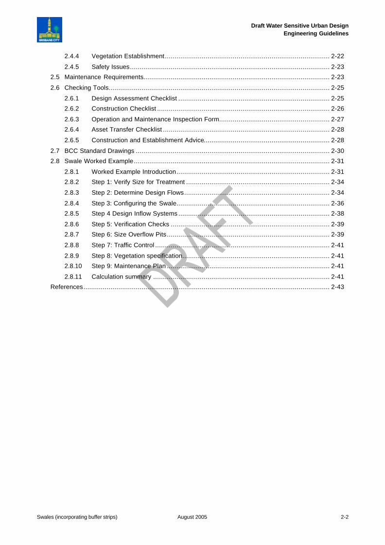
Chapter 2 Swales (incorporating Buffer Strips)
Grassed Swales Incorporated into Residential Streets in Brisbane
CHAPTER 2 SWALES (INCORPORATING BUFFER STRIPS) ........................................2-12.1 Introduction ......................................................................................................................... 2-3
2.2 Design Consideration for Swales .......................................................................................... 2-4
2.2.1 Landscape Design................................................................................................. 2-4
2.2.2 Hydraulic Design ................................................................................................... 2-4
2.2.3 Vegetation Types................................................................................................... 2-5
2.2.4 Driveway Crossings ............................................................................................... 2-6
2.2.5 Traffic Controls...................................................................................................... 2-6
2.2.6 Roof Water Discharge............................................................................................ 2-7
2.2.7 Services ................................................................................................................ 2-7
2.2.8 Signage ................................................................................................................ 2-7
2.3 Swale Design Process ......................................................................................................... 2-8
2.3.1 Step 1: Verifying Size for Treatment........................................................................ 2-8
2.3.2 Step 2: Determine Design Flows........................................................................... 2-10
2.3.3 Step 3: Configuring the Swale............................................................................... 2-10
2.3.4 Step 4: Design Inflow Systems ............................................................................. 2-13
2.3.5 Step 5: Verification Checks .................................................................................. 2-15
2.3.6 Step 6: Size Overflow Pits (Field Inlet Pits)............................................................ 2-15
2.3.7 Step 7: Allowances to Preclude Traffic on Swales .................................................. 2-16
2.3.8 Step 8: Vegetation Specification ........................................................................... 2-16
2.3.9 Step 9: Maintenance Plan .................................................................................... 2-16
2.3.10 Design Calculation Summary................................................................................ 2-16
2.4 Landscape Design Notes ................................................................................................... 2-18
2.4.1 Objectives ........................................................................................................... 2-18
2.4.2 Appropriate Plant Species .................................................................................... 2-21
2.4.3 Horticultural Topsoils for Swales (and Buffer Strips)............................................... 2-22
Draft Water Sensitive Urban DesignEngineering Guidelines
Swales (incorporating buffer strips) August 2005 2-2
2.4.4 Vegetation Establishment..................................................................................... 2-22
2.4.5 Safety Issues....................................................................................................... 2-23
2.5 Maintenance Requirements................................................................................................ 2-23
2.6 Checking Tools.................................................................................................................. 2-25
2.6.1 Design Assessment Checklist .............................................................................. 2-25
2.6.2 Construction Checklist ......................................................................................... 2-26
2.6.3 Operation and Maintenance Inspection Form......................................................... 2-27
2.6.4 Asset Transfer Checklist ...................................................................................... 2-28
2.6.5 Construction and Establishment Advice................................................................. 2-28
2.7 BCC Standard Drawings .................................................................................................... 2-30
2.8 Swale Worked Example..................................................................................................... 2-31
2.8.1 Worked Example Introduction............................................................................... 2-31
2.8.2 Step 1: Verify Size for Treatment .......................................................................... 2-34
2.8.3 Step 2: Determine Design Flows........................................................................... 2-34
2.8.4 Step 3: Configuring the Swale............................................................................... 2-36
2.8.5 Step 4 Design Inflow Systems .............................................................................. 2-38
2.8.6 Step 5: Verification Checks .................................................................................. 2-39
2.8.7 Step 6: Size Overflow Pits.................................................................................... 2-39
2.8.8 Step 7: Traffic Control .......................................................................................... 2-41
2.8.9 Step 8: Vegetation specification............................................................................ 2-41
2.8.10 Step 9: Maintenance Plan .................................................................................... 2-41
2.8.11 Calculation summary ........................................................................................... 2-41
References............................................................................................................................... 2-43
Draft Water Sensitive Urban DesignEngineering Guidelines
Swales (incorporating buffer strips) August 2005 2-3
2.1 Introduction
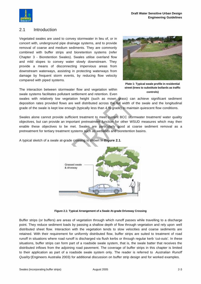
Vegetated swales are used to convey stormwater in lieu of, or inconcert with, underground pipe drainage systems, and to provideremoval of coarse and medium sediments. They are commonlycombined with buffer strips and bioretention systems (referChapter 3 - Bioretention Swales). Swales utilise overland flowand mild slopes to convey water slowly downstream. Theyprovide a means of disconnecting impervious areas fromdownstream waterways, assisting in protecting waterways fromdamage by frequent storm events, by reducing flow velocitycompared with piped systems.
The interaction between stormwater flow and vegetation withinswale systems facilitates pollutant settlement and retention. Evenswales with relatively low vegetation height (such as mown grass) can achieve significant sedimentdeposition rates provided flows are well distributed across the full width of the swale and the longitudinalgrade of the swale is kept low enough (typically less than 4 % grade) to maintain quiescent flow conditions.
Swales alone cannot provide sufficient treatment to meet current BCC stormwater treatment/ water qualityobjectives, but can provide an important pretreatment function for other WSUD measures which may thenenable these objectives to be met. Swales are particularly good at coarse sediment removal as apretreatment for tertiary treatment systems such as wetlands and bioretention basins.
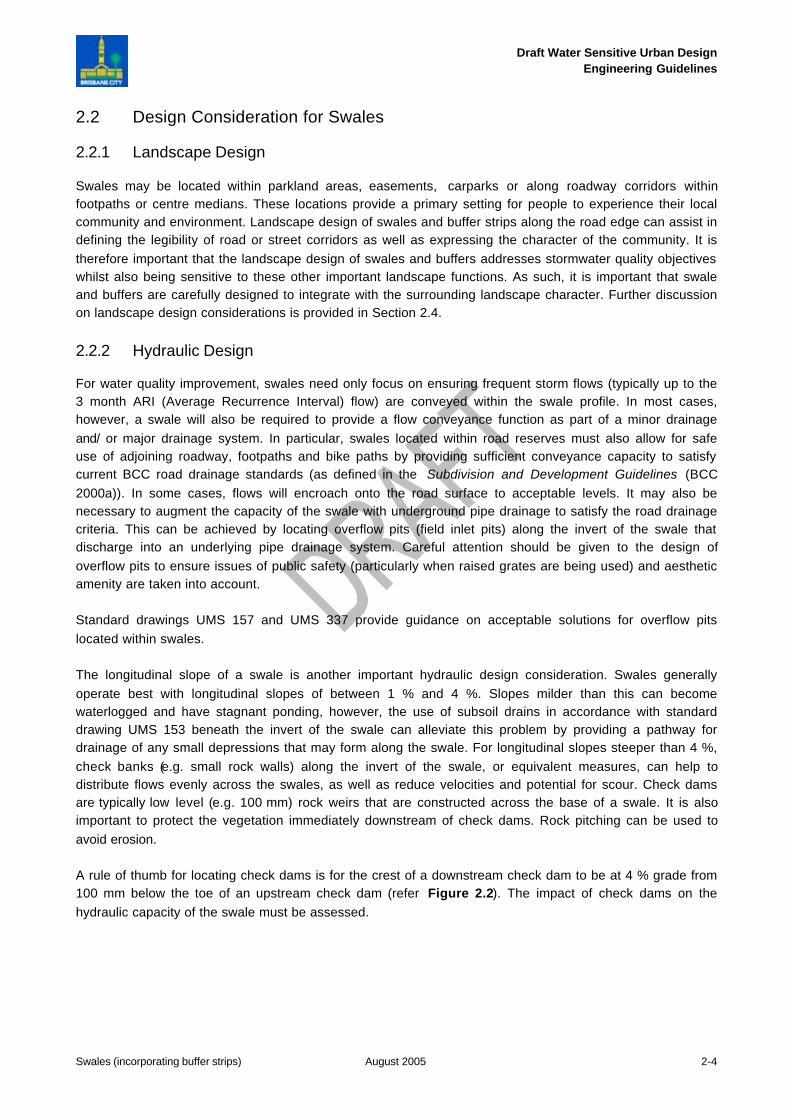
A typical sketch of a swale at-grade crossing is shown in Figure 2.1.
Figure 2.1: Typical Arrangement of a Swale At-grade Driveway Crossing
Buffer strips (or buffers) are areas of vegetation through which runoff passes while travelling to a dischargepoint. They reduce sediment loads by passing a shallow depth of flow through vegetation and rely upon welldistributed sheet flow. Interaction with the vegetation tends to slow velocities and coarse sediments areretained. With their requirement for uniformly distributed flow, buffer strips are suited to treatment of roadrunoff in situations where road runoff is discharged via flush kerbs or through regular kerb ‘cut-outs’. In thesesituations, buffer strips can form part of a roadside swale system, that is, the swale batter that receives thedistributed inflows from the adjoining road pavement. The coverage of buffer strips in this chapter is limitedto their application as part of a roadside swale system only. The reader is referred to Australian RunoffQuality (Engineers Australia 2003) for additional discussion on buffer strip design and for worked examples.
Plate 1: Typical swale profile in residentialstreet (trees to substitute bollards as traffic
controls)
Draft Water Sensitive Urban DesignEngineering Guidelines
Swales (incorporating buffer strips) August 2005 2-4
2.2 Design Consideration for Swales
2.2.1 Landscape Design
Swales may be located within parkland areas, easements, carparks or along roadway corridors withinfootpaths or centre medians. These locations provide a primary setting for people to experience their localcommunity and environment. Landscape design of swales and buffer strips along the road edge can assist indefining the legibility of road or street corridors as well as expressing the character of the community. It istherefore important that the landscape design of swales and buffers addresses stormwater quality objectiveswhilst also being sensitive to these other important landscape functions. As such, it is important that swaleand buffers are carefully designed to integrate with the surrounding landscape character. Further discussionon landscape design considerations is provided in Section 2.4.
2.2.2 Hydraulic Design
For water quality improvement, swales need only focus on ensuring frequent storm flows (typically up to the3 month ARI (Average Recurrence Interval) flow) are conveyed within the swale profile. In most cases,however, a swale will also be required to provide a flow conveyance function as part of a minor drainageand/ or major drainage system. In particular, swales located within road reserves must also allow for safeuse of adjoining roadway, footpaths and bike paths by providing sufficient conveyance capacity to satisfycurrent BCC road drainage standards (as defined in the Subdivision and Development Guidelines (BCC2000a)). In some cases, flows will encroach onto the road surface to acceptable levels. It may also benecessary to augment the capacity of the swale with underground pipe drainage to satisfy the road drainagecriteria. This can be achieved by locating overflow pits (field inlet pits) along the invert of the swale thatdischarge into an underlying pipe drainage system. Careful attention should be given to the design ofoverflow pits to ensure issues of public safety (particularly when raised grates are being used) and aestheticamenity are taken into account.
Standard drawings UMS 157 and UMS 337 provide guidance on acceptable solutions for overflow pitslocated within swales.
The longitudinal slope of a swale is another important hydraulic design consideration. Swales generallyoperate best with longitudinal slopes of between 1 % and 4 %. Slopes milder than this can becomewaterlogged and have stagnant ponding, however, the use of subsoil drains in accordance with standarddrawing UMS 153 beneath the invert of the swale can alleviate this problem by providing a pathway fordrainage of any small depressions that may form along the swale. For longitudinal slopes steeper than 4 %,check banks (e.g. small rock walls) along the invert of the swale, or equivalent measures, can help todistribute flows evenly across the swales, as well as reduce velocities and potential for scour. Check damsare typically low level (e.g. 100 mm) rock weirs that are constructed across the base of a swale. It is alsoimportant to protect the vegetation immediately downstream of check dams. Rock pitching can be used toavoid erosion.
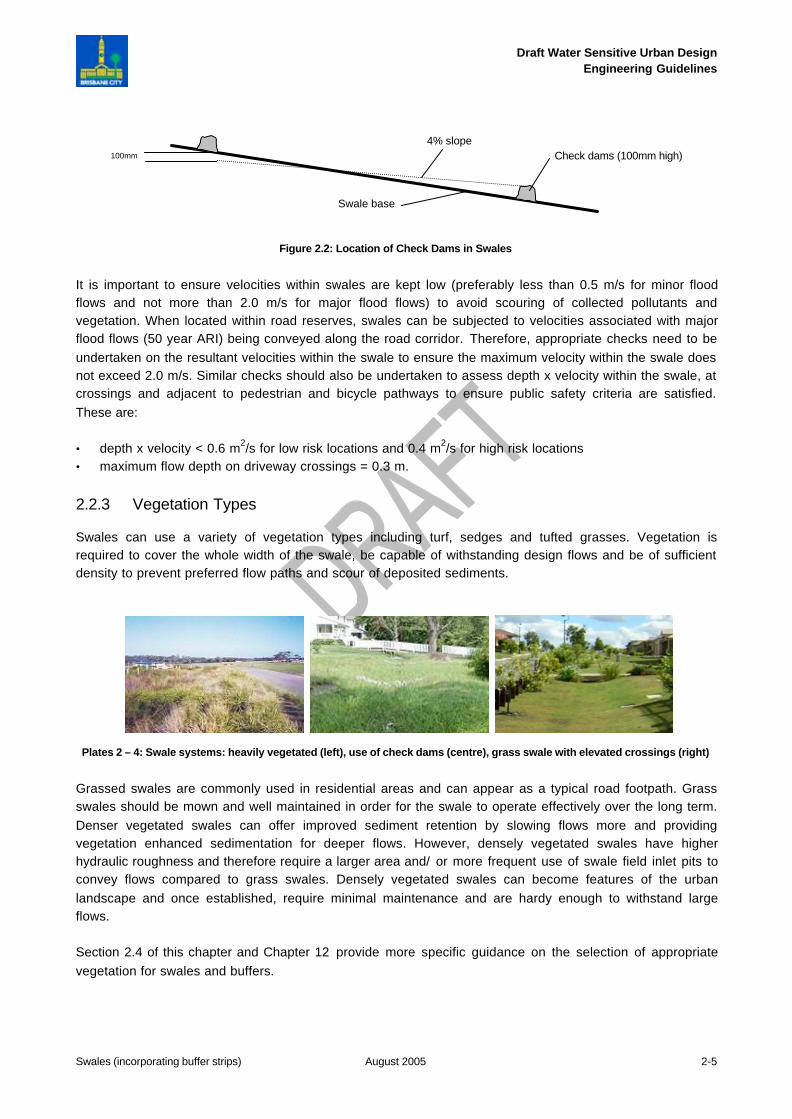
A rule of thumb for locating check dams is for the crest of a downstream check dam to be at 4 % grade from100 mm below the toe of an upstream check dam (refer Figure 2.2). The impact of check dams on thehydraulic capacity of the swale must be assessed.
Draft Water Sensitive Urban DesignEngineering Guidelines
Swales (incorporating buffer strips) August 2005 2-5
Figure 2.2: Location of Check Dams in Swales
It is important to ensure velocities within swales are kept low (preferably less than 0.5 m/s for minor floodflows and not more than 2.0 m/s for major flood flows) to avoid scouring of collected pollutants andvegetation. When located within road reserves, swales can be subjected to velocities associated with majorflood flows (50 year ARI) being conveyed along the road corridor. Therefore, appropriate checks need to beundertaken on the resultant velocities within the swale to ensure the maximum velocity within the swale doesnot exceed 2.0 m/s. Similar checks should also be undertaken to assess depth x velocity within the swale, atcrossings and adjacent to pedestrian and bicycle pathways to ensure public safety criteria are satisfied.These are:
• depth x velocity < 0.6 m2/s for low risk locations and 0.4 m2/s for high risk locations• maximum flow depth on driveway crossings = 0.3 m.
2.2.3 Vegetation Types
Swales can use a variety of vegetation types including turf, sedges and tufted grasses. Vegetation isrequired to cover the whole width of the swale, be capable of withstanding design flows and be of sufficientdensity to prevent preferred flow paths and scour of deposited sediments.
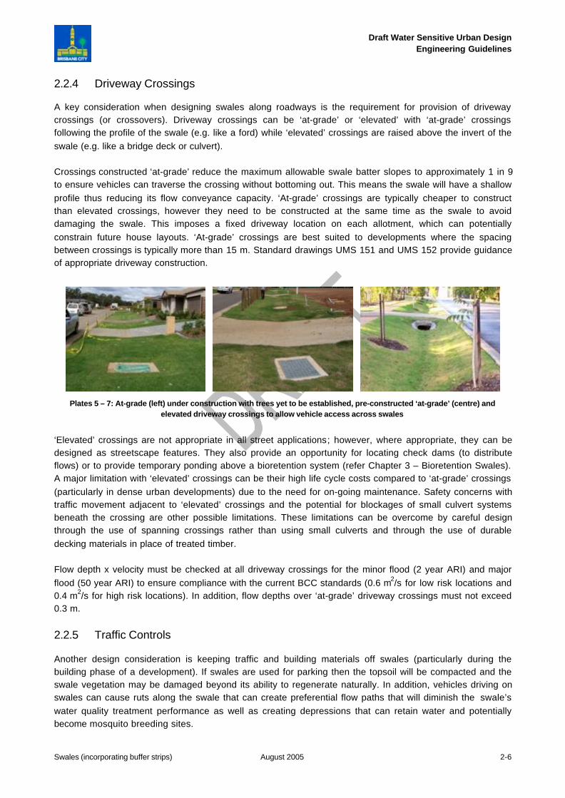
Plates 2 – 4: Swale systems: heavily vegetated (left), use of check dams (centre), grass swale with elevated crossings (right)
Grassed swales are commonly used in residential areas and can appear as a typical road footpath. Grassswales should be mown and well maintained in order for the swale to operate effectively over the long term.Denser vegetated swales can offer improved sediment retention by slowing flows more and providingvegetation enhanced sedimentation for deeper flows. However, densely vegetated swales have higherhydraulic roughness and therefore require a larger area and/ or more frequent use of swale field inlet pits toconvey flows compared to grass swales. Densely vegetated swales can become features of the urbanlandscape and once established, require minimal maintenance and are hardy enough to withstand largeflows.
Section 2.4 of this chapter and Chapter 12 provide more specific guidance on the selection of appropriatevegetation for swales and buffers.
4% slopeCheck dams (100mm high)
Swale base
100mm
Draft Water Sensitive Urban DesignEngineering Guidelines
Swales (incorporating buffer strips) August 2005 2-6
2.2.4 Driveway Crossings
A key consideration when designing swales along roadways is the requirement for provision of drivewaycrossings (or crossovers). Driveway crossings can be ‘at-grade’ or ‘elevated’ with ‘at-grade’ crossingsfollowing the profile of the swale (e.g. like a ford) while ‘elevated’ crossings are raised above the invert of theswale (e.g. like a bridge deck or culvert).
Crossings constructed ‘at-grade’ reduce the maximum allowable swale batter slopes to approximately 1 in 9to ensure vehicles can traverse the crossing without bottoming out. This means the swale will have a shallowprofile thus reducing its flow conveyance capacity. ‘At-grade’ crossings are typically cheaper to constructthan elevated crossings, however they need to be constructed at the same time as the swale to avoiddamaging the swale. This imposes a fixed driveway location on each allotment, which can potentiallyconstrain future house layouts. ‘At-grade’ crossings are best suited to developments where the spacingbetween crossings is typically more than 15 m. Standard drawings UMS 151 and UMS 152 provide guidanceof appropriate driveway construction.
Plates 5 – 7: At-grade (left) under construction with trees yet to be established, pre-constructed ‘at-grade’ (centre) andelevated driveway crossings to allow vehicle access across swales
‘Elevated’ crossings are not appropriate in all street applications; however, where appropriate, they can bedesigned as streetscape features. They also provide an opportunity for locating check dams (to distributeflows) or to provide temporary ponding above a bioretention system (refer Chapter 3 – Bioretention Swales).A major limitation with ‘elevated’ crossings can be their high life cycle costs compared to ‘at-grade’ crossings(particularly in dense urban developments) due to the need for on-going maintenance. Safety concerns withtraffic movement adjacent to ‘elevated’ crossings and the potential for blockages of small culvert systemsbeneath the crossing are other possible limitations. These limitations can be overcome by careful designthrough the use of spanning crossings rather than using small culverts and through the use of durabledecking materials in place of treated timber.
Flow depth x velocity must be checked at all driveway crossings for the minor flood (2 year ARI) and majorflood (50 year ARI) to ensure compliance with the current BCC standards (0.6 m2/s for low risk locations and0.4 m2/s for high risk locations). In addition, flow depths over ‘at-grade’ driveway crossings must not exceed0.3 m.
2.2.5 Traffic Controls
Another design consideration is keeping traffic and building materials off swales (particularly during thebuilding phase of a development). If swales are used for parking then the topsoil will be compacted and theswale vegetation may be damaged beyond its ability to regenerate naturally. In addition, vehicles driving onswales can cause ruts along the swale that can create preferential flow paths that will diminish the swale’swater quality treatment performance as well as creating depressions that can retain water and potentiallybecome mosquito breeding sites.
Draft Water Sensitive Urban DesignEngineering Guidelines
Swales (incorporating buffer strips) August 2005 2-7
To prevent vehicles driving on swales and inadvertent placement of building materials, it is necessary toconsider appropriate traffic control solutions as part of the swale design. These can include planting theswale with dense vegetation that will discourage the movement of vehicles onto the swale or, if densevegetation cannot be used, providing physical barriers such as kerb and channel (with breaks to allowdistributed water entry to the swale) or bollards and/ or street tree planting.
Kerb and channel should be used at all corners, intersections, cul-de-sac heads and at traffic calmingdevices to ensure correct driving path is taken. For all of these applications, the kerb and channel is toextend 5 m beyond tangent points. The transition from barrier or lay back type kerb to flush kerbs and viceversa is to be done in a way that avoids creation of low points that cause ponding onto the road pavement(refer to standard drawing UMS 151).
Where bollards are used, consideration should be given to intermixing mature tree plantings with the bollardsto break the visual monotony created by a continuous row of bollards. Bollards and any landscaping (soft orhard) must be located at least 600 mm from back of kerb and spaced at a maximum of 1.5 m apart.
2.2.6 Roof Water Discharge
Roof runoff can contain a range of stormwater pollutants including nitrogen washed from the atmosphereduring rainfall events. Rainfall is consistently the major source of nitrogen in urban stormwater runoff(Duncan 1995) and inorganic nitrogen concentrations in rainfall often exceed the threshold level for algalblooms (Weibel et al. 1966). Roof water should therefore be discharged onto the surface of the swale forsubsequent conveyance and treatment by the swale (and downstream treatment measures) before beingdischarged to receiving aquatic environments. Depending on the depth of the roof water drainage systemand the finished levels of the swale, this may require the use of a small surcharge pit located within the invertof the swale to allow the roof water to surcharge to the swale. Any residual water in the surcharge pit can bedischarged to the underlying subsoil drainage by providing perforations in the base and sides of thesurcharge pit. If a surcharge pit is used, an inspection chamber along the roof water drainage line is to beprovided within the property boundary. Surcharge pits are discussed further in Section 2.3.4.3.
Roof water should only be directly connected to an underground pipe drainage system if an appropriate levelof stormwater treatment is provided along (or at the outfall of) the pipe drainage system. Details of roof waterdrainage connection are shown in standard drawing UMS 154.
2.2.7 Services
Swales located within BCC standard road reserves are to have services located within the services corridorsdefined on standard drawing UMS 151. Sewers located beneath swales are to be fully welded polyethylenepipes with rodding points. Care should be taken to ensure the service conduits do not compromise theperformance of the swale.
2.2.8 Signage
Signage explaining the function of the swale or buffer strip is acceptable but must be approved by BCC. Thelocation and method of signage must not endanger public safety and is to be in accordance with BCC’sstandards and Local Laws.
Draft Water Sensitive Urban DesignEngineering Guidelines
Swales (incorporating buffer strips) August 2005 2-8
2.3 Swale Design Process
The design process for swales involves in the first instance designing the swale to meet flow conveyancerequirements and then ensuring the swale has the necessary design features to optimise its stormwaterquality treatment performance.
The key design steps are:
1. verify size for treatment
2. determine design flows
3. dimension the swale with consideration of site constraints:
a. swale width and side slopes
b. maximum swale length (i.e. length between overflow pits)
4. design of inflow systems
5. verify design:
a. scour velocity checks
b. safety checks:
− depth x velocity
− maximum depth over crossings
c. confirm treatment performance
6. size overflow pits (field inlet pits)
7. allowances to preclude traffic on swales
8. specify plant species and planting densities
9. provision for maintenance, including written maintenance plan.
Each of these design steps is discussed in the following sections. A worked example illustrating applicationof the design process on a case study site is presented in Section 2.8.
2.3.1 Step 1: Verifying Size for Treatment
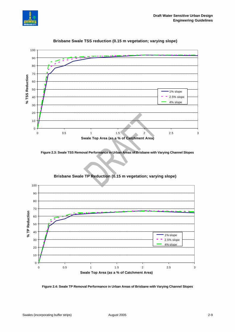
The curves below (Figure 2.3 to 2.5) show the pollutant removal performance expected for a swale with a 1m base and 1 in 9 side slopes. The curves are based on the performance of a system in urban areas ofBrisbane (i.e. including residential, commercial and industrial areas) and present performance for a varyinglongitudinal slope. The curves were derived using the Model for Urban Stormwater ImprovementConceptualisation (MUSIC)(CRCCH 2005).
Where local data are available, or if the configuration of the system varies to that described below, MUSICshould be used to estimate pollutant removal performances. MUSIC results will always supersede thecurves.
The curves were derived assuming the systems are stand alone system (i.e. not part of a treatment train)and have the following characteristics:
• top width 4.5 m• base width 1 m• side slopes 1 in 9• vegetation height 150 mm (however for vegetation of between 50-250 mm the curves are still valid).
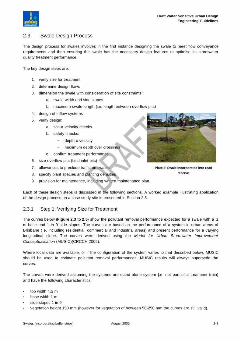
Plate 8: Swale incorporated into road
reserve
Draft Water Sensitive Urban DesignEngineering Guidelines
Swales (incorporating buffer strips) August 2005 2-9
Brisbane Swale TSS reduction (0.15 m vegetation; varying slope)
0
10
20
30
40
50
60
70
80
90
100
0 0.5 1 1.5 2 2.5 3
Swale Top Area (as a % of Catchment Area)
% T
SS
Red
uct
ion
1% slope
2.5% slope
4% slope
Brisbane Swale TP Reduction (0.15 m vegetation; varying slope)
0
10
20
30
40
50
60
70
80
90
100
0 0.5 1 1.5 2 2.5 3
Swale Top Area (as a % of Catchment Area)
% T
P R
edu
ctio
n
1% slope
2.5% slope
4% slope
Figure 2.3: Swale TSS Removal Performance in Urban Areas of Brisbane with Varying Channel Slopes
Figure 2.4: Swale TP Removal Performance in Urban Areas of Brisbane with Varying Channel Slopes
Draft Water Sensitive Urban DesignEngineering Guidelines
Swales (incorporating buffer strips) August 2005 2-10
Brisbane Swale TN Reduction (0.15 m vegetation; varying slope)
0
10
20
30
40
50
60
70
80
90
100
0 0.5 1 1.5 2 2.5 3
Swale Top Area (as a % of Catchment Area)
% T
N R
edu
ctio
n
1% slope
2.5% slope
4% slope
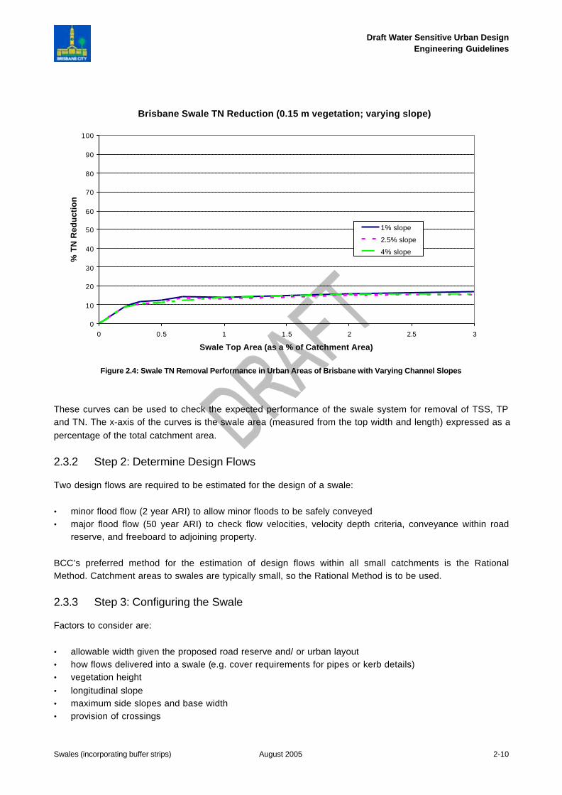
Figure 2.4: Swale TN Removal Performance in Urban Areas of Brisbane with Varying Channel Slopes
These curves can be used to check the expected performance of the swale system for removal of TSS, TPand TN. The x-axis of the curves is the swale area (measured from the top width and length) expressed as apercentage of the total catchment area.
2.3.2 Step 2: Determine Design Flows
Two design flows are required to be estimated for the design of a swale:
• minor flood flow (2 year ARI) to allow minor floods to be safely conveyed• major flood flow (50 year ARI) to check flow velocities, velocity depth criteria, conveyance within road
reserve, and freeboard to adjoining property.
BCC’s preferred method for the estimation of design flows within all small catchments is the RationalMethod. Catchment areas to swales are typically small, so the Rational Method is to be used.
2.3.3 Step 3: Configuring the Swale
Factors to consider are:
• allowable width given the proposed road reserve and/ or urban layout• how flows delivered into a swale (e.g. cover requirements for pipes or kerb details)• vegetation height• longitudinal slope• maximum side slopes and base width• provision of crossings
Draft Water Sensitive Urban DesignEngineering Guidelines
Swales (incorporating buffer strips) August 2005 2-11
• requirements of Queensland Urban Drainage Manual (QUDM) (DPI et al. 1993).
Depending on which of the above characteristics are fixed, other variables may be adjusted to derive theoptimal swale dimensions for the given site conditions. The following sections outline some considerations inrelation to configuring a swale.
2.3.3.1 Swale Width and Side Slopes
The maximum width of swale is usually determined from an urban layout and at the concept design stage.BCC standard drawing UMS 151 presents examples of swale profiles that can be provided within standardBCC road reserves. Where the swale width is not constrained by an urban layout (e.g. when located within alarge parkland area), then the width of the swale can be selected based on consideration of landscapeobjectives, maximum side slopes for ease of maintenance and public safety, hydraulic capacity required toconvey the desired design flow, and treatment performance requirements. The maximum swale width needsto be identified early in the design process as it dictates the remaining steps in the swale design process.
Selection of an appropriate side slope for swales located in parks, easements or median strips is heavilydependant on site constraints, and swale side slopes are typically between 1 in 10 and 1 in 3.
For swales located adjacent to roads, side slopes will typically be dictated by the driveway crossing. Wherethere are no driveway crossings then the maximum swale side slopes will be established from ease ofmaintenance and public safety considerations. Council prefers the use of ‘at-grade’ crossings that will requirethe swale to have 1:9 side slopes with a nominal 0.5 m flat base to provide sufficient transitions to allow fortraffic movement across the crossing. Flatter swale side slopes can be adopted, but this will reduce thedepth of the swale and its conveyance capacity. Where ‘elevated’ crossings are used, swale side slopeswould typically be between 1 in 6 and 1 in 3. ‘Elevated’ crossings will require provision for drainage under thecrossings with a culvert or similar. The selection of crossing type should be made in consultation with urbanand landscape designers. Standard drawing UMS 152 provides guidance on driveway construction.
2.3.3.2 Maximum Length of a Swale
Provided the water quality function of the swale is met, the maximum length of a swale is the distance alonga swale before an overflow pit (field inlet pit) is required to drain the swale to an underlying pipe drainagesystem.
The maximum length of a swale located within parkland areas and easements is calculated as the distancealong the swale to the point where the flow in the swale from the contributing catchment (for the specificdesign flood frequency) exceeds the bank full capacity of the swale. For example, if the swale is to conveythe minor flood flow (2 year ARI) without overflowing, then the maximum swale length would be determinedas the distance along the swale to the point where the 2 year ARI flow from the contributing catchment isequivalent to the bank full flow capacity of the swale (bank full flow capacity is determined using Manning’sequation as discussed below).
The maximum length of a swale located along a roadway is calculated as the distance along the swale to thepoint where flow on the adjoining road pavement (or road reserve) no longer complies with current BCC roaddesign standards (for both the minor and major flood flows) as defined in the Subdivision and DevelopmentGuidelines (BCC 2000a) and QUDM (DPI et al. 1993).
Draft Water Sensitive Urban DesignEngineering Guidelines
Swales (incorporating buffer strips) August 2005 2-12
2.3.3.3 Swale Capacity – Manning’s Equation and Selection of Manning’s n
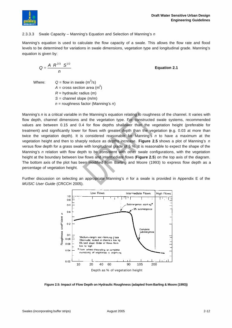
Manning’s equation is used to calculate the flow capacity of a swale. This allows the flow rate and floodlevels to be determined for variations in swale dimensions, vegetation type and longitudinal grade. Manning’sequation is given by:
nSRAQ
1/22/3 ⋅⋅= Equation 2.1
Where: Q = flow in swale (m3/s)A = cross section area (m2)R = hydraulic radius (m)S = channel slope (m/m)n = roughness factor (Manning’s n)
Manning’s n is a critical variable in the Manning’s equation relating to roughness of the channel. It varies withflow depth, channel dimensions and the vegetation type. For constructed swale systems, recommendedvalues are between 0.15 and 0.4 for flow depths shallower than the vegetation height (preferable fortreatment) and significantly lower for flows with greater depth than the vegetation (e.g. 0.03 at more thantwice the vegetation depth). It is considered reasonable for Manning’s n to have a maximum at thevegetation height and then to sharply reduce as depths increase. Figure 2.5 shows a plot of Manning’s nversus flow depth for a grass swale with longitudinal grade of 5 %. It is reasonable to expect the shape of theManning’s n relation with flow depth to be consistent with other swale configurations, with the vegetationheight at the boundary between low flows and intermediate flows (Figure 2.5) on the top axis of the diagram.The bottom axis of the plot has been modified from Barling and Moore (1993) to express flow depth as apercentage of vegetation height.
Further discussion on selecting an appropriate Manning’s n for a swale is provided in Appendix E of theMUSIC User Guide (CRCCH 2005).
Figure 2.5: Impact of Flow Depth on Hydraulic Roughness (adapted from Barling & Moore (1993))
8010 20 40 60 90 105 2008010 20 40 60 90 105 200
Depth as % of vegetation height
Draft Water Sensitive Urban DesignEngineering Guidelines
Swales (incorporating buffer strips) August 2005 2-13
2.3.4 Step 4: Design Inflow Systems
Inflows to swales can be via distributed runoff (e.g. from flush kerbs along a road) or point outlets such aspipe culverts. Combinations of these two inflow pathways can also be used.
2.3.4.1 Distributed Inflow
An advantage of flows entering a swale system in a distributed manner (i.e. entering perpendicular to thedirection of the swale) is that flow depths are kept as shallow sheet flow, which maximises contact with theswale vegetation on the batter receiving the distributed inflows. This swale batter is often referred to as abuffer. The function of the buffer is to ensure there is dense vegetation growth, flow depths are shallow(below the vegetation height) and erosion is avoided. The buffer provides good pretreatment (i.e. significantcoarse sediment removal) prior to flows being conveyed along the swale.
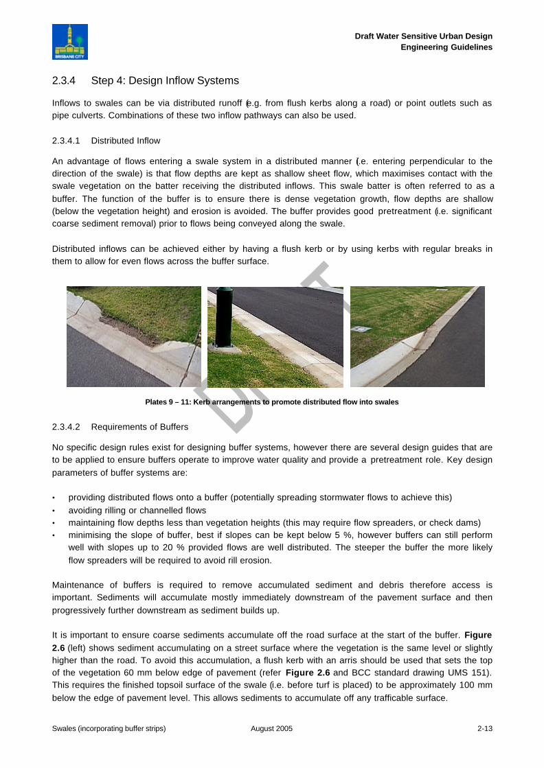
Distributed inflows can be achieved either by having a flush kerb or by using kerbs with regular breaks inthem to allow for even flows across the buffer surface.
Plates 9 – 11: Kerb arrangements to promote distributed flow into swales
2.3.4.2 Requirements of Buffers
No specific design rules exist for designing buffer systems, however there are several design guides that areto be applied to ensure buffers operate to improve water quality and provide a pretreatment role. Key designparameters of buffer systems are:
• providing distributed flows onto a buffer (potentially spreading stormwater flows to achieve this)• avoiding rilling or channelled flows• maintaining flow depths less than vegetation heights (this may require flow spreaders, or check dams)• minimising the slope of buffer, best if slopes can be kept below 5 %, however buffers can still perform
well with slopes up to 20 % provided flows are well distributed. The steeper the buffer the more likelyflow spreaders will be required to avoid rill erosion.
Maintenance of buffers is required to remove accumulated sediment and debris therefore access isimportant. Sediments will accumulate mostly immediately downstream of the pavement surface and thenprogressively further downstream as sediment builds up.
It is important to ensure coarse sediments accumulate off the road surface at the start of the buffer. Figure2.6 (left) shows sediment accumulating on a street surface where the vegetation is the same level or slightlyhigher than the road. To avoid this accumulation, a flush kerb with an arris should be used that sets the topof the vegetation 60 mm below edge of pavement (refer Figure 2.6 and BCC standard drawing UMS 151).This requires the finished topsoil surface of the swale (i.e. before turf is placed) to be approximately 100 mmbelow the edge of pavement level. This allows sediments to accumulate off any trafficable surface.
Draft Water Sensitive Urban DesignEngineering Guidelines
Swales (incorporating buffer strips) August 2005 2-14
PLAN
Drainage holes to be drilled in base of pit
Secured grate
Pipe connection from allotment
ELEVATION
Vertical drainage slots
Removeable geofabric for cleaning sediment accumulation
PLAN
Drainage holes to be drilled in base of pit
Secured grate
Pipe connection from allotment
ELEVATION
Vertical drainage slots
Removeable geofabric for cleaning sediment accumulation
Secured grate
Pipe connection from allotment
ELEVATION
Vertical drainage slots
Removeable geofabric for cleaning sediment accumulation
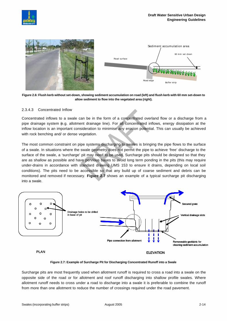
Figure 2.6: Flush kerb without set-down, showing sediment accumulation on road (left) and flush kerb with 60 mm set-down toallow sediment to flow into the vegetated area (right).
2.3.4.3 Concentrated Inflow
Concentrated inflows to a swale can be in the form of a concentrated overland flow or a discharge from apipe drainage system (e.g. allotment drainage line). For all concentrated inflows, energy dissipation at theinflow location is an important consideration to minimise any erosion potential. This can usually be achievedwith rock benching and/ or dense vegetation.
The most common constraint on pipe systems discharging to swales is bringing the pipe flows to the surfaceof a swale. In situations where the swale geometry does not permit the pipe to achieve ‘free’ discharge to thesurface of the swale, a ‘surcharge’ pit may need to be used. Surcharge pits should be designed so that theyare as shallow as possible and have pervious bases to avoid long term ponding in the pits (this may requireunder-drains in accordance with standard drawing UMS 153 to ensure it drains, depending on local soilconditions). The pits need to be accessible so that any build up of coarse sediment and debris can bemonitored and removed if necessary. Figure 2.7 shows an example of a typical surcharge pit discharginginto a swale.
Figure 2.7: Example of Surcharge Pit for Discharging Concentrated Runoff into a Swale
Surcharge pits are most frequently used when allotment runoff is required to cross a road into a swale on theopposite side of the road or for allotment and roof runoff discharging into shallow profile swales. Whereallotment runoff needs to cross under a road to discharge into a swale it is preferable to combine the runofffrom more than one allotment to reduce the number of crossings required under the road pavement.
Road edge
Road surface
60 mm set down
Buffer strip
Sediment accumulation area
Draft Water Sensitive Urban DesignEngineering Guidelines
Swales (incorporating buffer strips) August 2005 2-15
2.3.5 Step 5: Verification Checks
2.3.5.1 Vegetation Scour Velocity Check
Potential scour velocities are checked by applying Manning’s equation to the swale design to ensure thefollowing criteria is met:
• Less than 0.5 m/s for minor flood (2 year ARI) discharge.• Less than 2.0m/s for major flood (50 year ARI) discharge.
2.3.5.2 Velocity and Depth Check – Safety
As swales are generally accessible by the public it is important to check that depth x velocity within theswale, at crossings and adjacent to pedestrian and bicycle pathways satisfies the following public safetycriteria:
• depth x velocity < 0.6 m2/s for low risk locations and 0.4 m2/s for high risk locations as defined in QUDM(DPI et al. 1993).
• maximum depth of flow over ‘at-grade’ crossings = 0.3 m
2.3.5.3 Confirm Treatment Performance
If the previous two checks are satisfactory then the swale design is adequate from a conveyance functionperspective and it is now necessary to reconfirm the treatment performance of the swale by reference backto the information presented in Section 2.3.1.
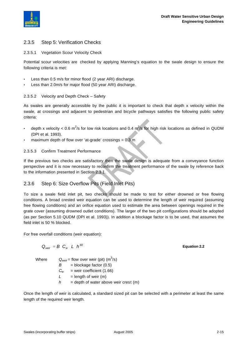
2.3.6 Step 6: Size Overflow Pits (Field Inlet Pits)
To size a swale field inlet pit, two checks should be made to test for either drowned or free flowingconditions. A broad crested weir equation can be used to determine the length of weir required (assumingfree flowing conditions) and an orifice equation used to estimate the area between openings required in thegrate cover (assuming drowned outlet conditions). The larger of the two pit configurations should be adopted(as per Section 5.10 QUDM (DPI et al. 1993)). In addition a blockage factor is to be used, that assumes thefield inlet is 50 % blocked.
For free overfall conditions (weir equation):
3/2hLCBQ wweir ⋅⋅⋅= Equation 2.2
Where Qweir = flow over weir (pit) (m3/s)B = blockage factor (0.5)Cw = weir coefficient (1.66)L = length of weir (m)h = depth of water above weir crest (m)
Once the length of weir is calculated, a standard sized pit can be selected with a perimeter at least the samelength of the required weir length.
Draft Water Sensitive Urban DesignEngineering Guidelines
Swales (incorporating buffer strips) August 2005 2-16
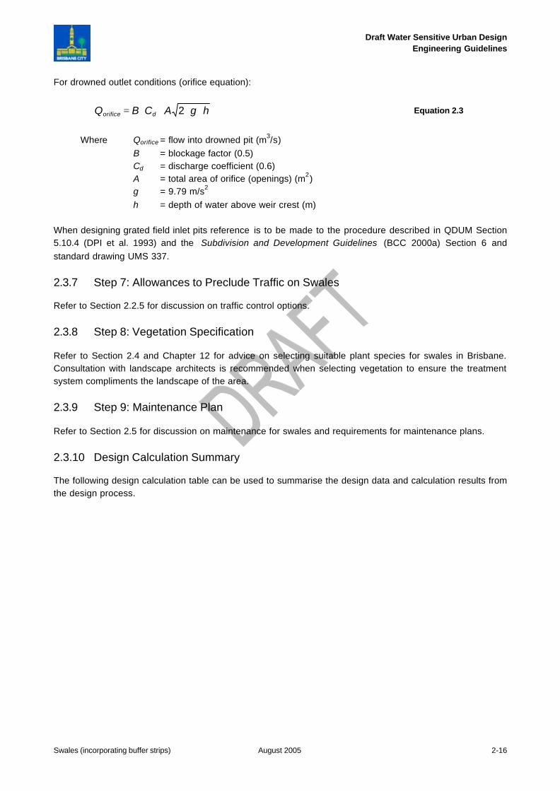
For drowned outlet conditions (orifice equation):
hgACBQ dorifice ⋅⋅⋅⋅= 2 Equation 2.3
Where Qorifice = flow into drowned pit (m3/s)B = blockage factor (0.5)Cd = discharge coefficient (0.6)A = total area of orifice (openings) (m2)g = 9.79 m/s2
h = depth of water above weir crest (m)
When designing grated field inlet pits reference is to be made to the procedure described in QDUM Section5.10.4 (DPI et al. 1993) and the Subdivision and Development Guidelines (BCC 2000a) Section 6 andstandard drawing UMS 337.
2.3.7 Step 7: Allowances to Preclude Traffic on Swales
Refer to Section 2.2.5 for discussion on traffic control options.
2.3.8 Step 8: Vegetation Specification
Refer to Section 2.4 and Chapter 12 for advice on selecting suitable plant species for swales in Brisbane.Consultation with landscape architects is recommended when selecting vegetation to ensure the treatmentsystem compliments the landscape of the area.
2.3.9 Step 9: Maintenance Plan
Refer to Section 2.5 for discussion on maintenance for swales and requirements for maintenance plans.
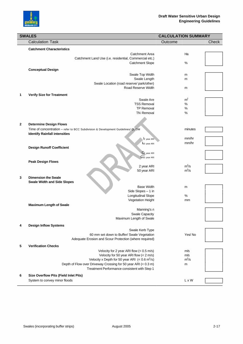
2.3.10 Design Calculation Summary
The following design calculation table can be used to summarise the design data and calculation results fromthe design process.
Draft Water Sensitive Urban DesignEngineering Guidelines
Swales (incorporating buffer strips) August 2005 2-17
SWALES CALCULATION SUMMARYCalculation Task Outcome Check
Catchment CharacteristicsCatchment Area Ha
Catchment Land Use (i.e. residential, Commercial etc.)Catchment Slope %
Conceptual DesignSwale Top Width m
Swale Length mSwale Location (road reserve/ park/other)
Road Reserve Width m
1 Verify Size for TreatmentSwale Are m2
TSS Removal %TP Removal %TN Removal %
2 Determine Design FlowsTime of concentration – refer to BCC Subdivision & Development Guidelines/ QUDM minutesIdentify Rainfall intensities
I2 year ARI mm/hrI50 year ARI mm/hr
Design Runoff CoefficientC2 year ARI
C50 year ARI
Peak Design Flows2 year ARI m3/s
50 year ARI m3/s
3 Dimension the SwaleSwale Width and Side Slopes
Base Width mSide Slopes – 1 inLongitudinal Slope %Vegetation Height mm
Maximum Length of SwaleManning’s n
Swale CapacityMaximum Length of Swale
4 Design Inflow SystemsSwale Kerb Type
60 mm set down to Buffer/ Swale Vegetation Yes/ NoAdequate Erosion and Scour Protection (where required)
5 Verification ChecksVelocity for 2 year ARI flow (< 0.5 m/s) m/sVelocity for 50 year ARI flow (< 2 m/s) m/s
Velocity x Depth for 50 year ARI (< 0.6 m2/s) m2/sDepth of Flow over Driveway Crossing for 50 year ARI (< 0.3 m) m
Treatment Performance consistent with Step 1
6 Size Overflow Pits (Field Inlet Pits)System to convey minor floods L x W
Draft Water Sensitive Urban DesignEngineering Guidelines
Swales (incorporating buffer strips) August 2005 2-18
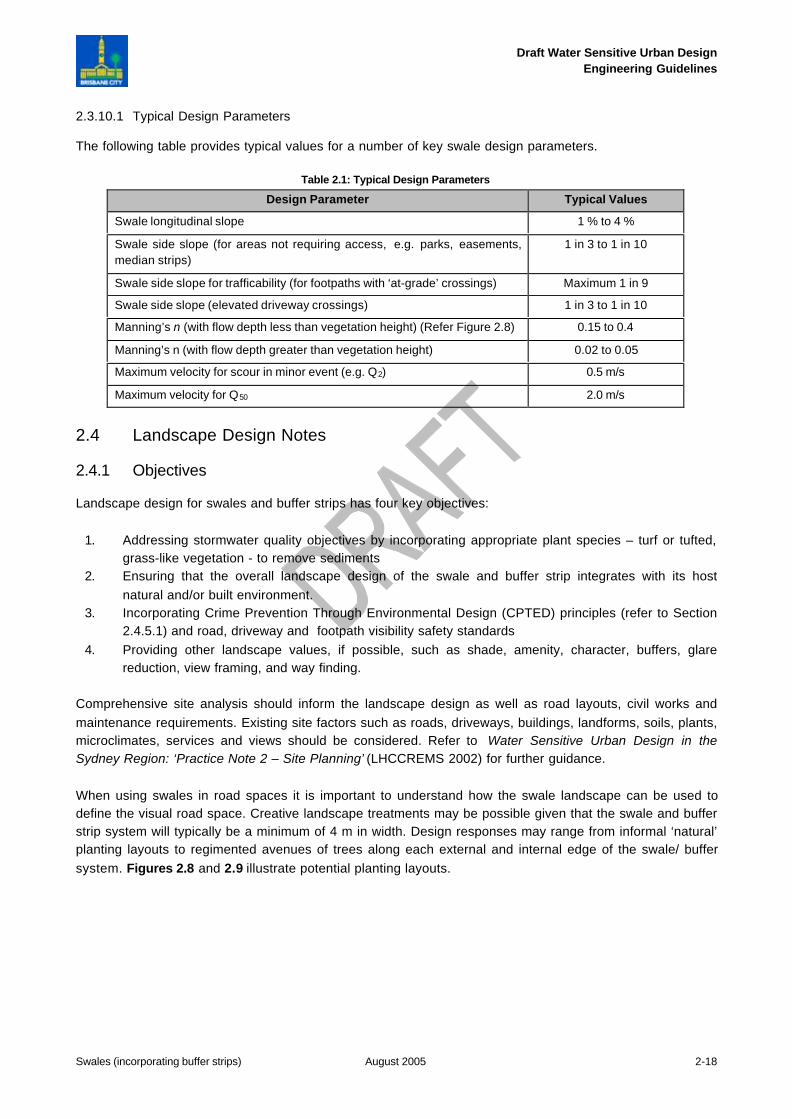
2.3.10.1 Typical Design Parameters
The following table provides typical values for a number of key swale design parameters.
Table 2.1: Typical Design Parameters
Design Parameter Typical Values
Swale longitudinal slope 1 % to 4 %
Swale side slope (for areas not requiring access, e.g. parks, easements,median strips)
1 in 3 to 1 in 10
Swale side slope for trafficability (for footpaths with ‘at-grade’ crossings) Maximum 1 in 9
Swale side slope (elevated driveway crossings) 1 in 3 to 1 in 10
Manning’s n (with flow depth less than vegetation height) (Refer Figure 2.8) 0.15 to 0.4
Manning’s n (with flow depth greater than vegetation height) 0.02 to 0.05
Maximum velocity for scour in minor event (e.g. Q2) 0.5 m/s
Maximum velocity for Q50 2.0 m/s
2.4 Landscape Design Notes
2.4.1 Objectives
Landscape design for swales and buffer strips has four key objectives:
1. Addressing stormwater quality objectives by incorporating appropriate plant species – turf or tufted,grass-like vegetation - to remove sediments
2. Ensuring that the overall landscape design of the swale and buffer strip integrates with its hostnatural and/or built environment.
3. Incorporating Crime Prevention Through Environmental Design (CPTED) principles (refer to Section2.4.5.1) and road, driveway and footpath visibility safety standards
4. Providing other landscape values, if possible, such as shade, amenity, character, buffers, glarereduction, view framing, and way finding.
Comprehensive site analysis should inform the landscape design as well as road layouts, civil works andmaintenance requirements. Existing site factors such as roads, driveways, buildings, landforms, soils, plants,microclimates, services and views should be considered. Refer to Water Sensitive Urban Design in theSydney Region: ‘Practice Note 2 – Site Planning’ (LHCCREMS 2002) for further guidance.
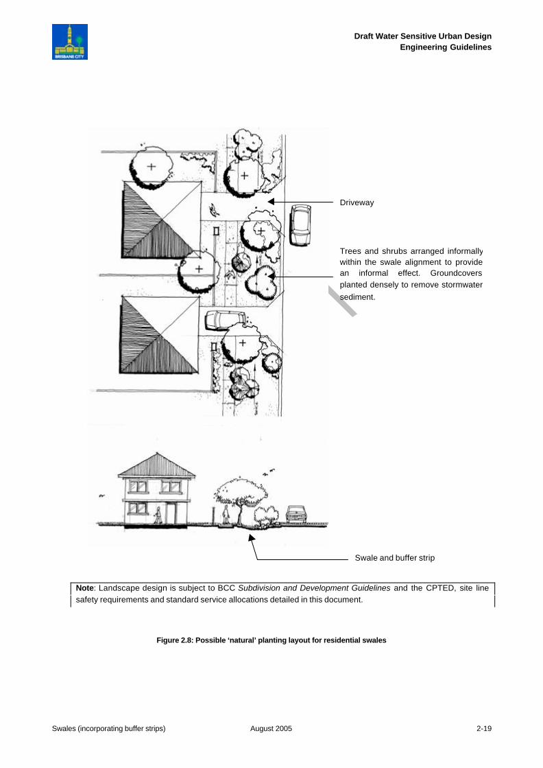
When using swales in road spaces it is important to understand how the swale landscape can be used todefine the visual road space. Creative landscape treatments may be possible given that the swale and bufferstrip system will typically be a minimum of 4 m in width. Design responses may range from informal ‘natural’planting layouts to regimented avenues of trees along each external and internal edge of the swale/ buffersystem. Figures 2.8 and 2.9 illustrate potential planting layouts.
Draft Water Sensitive Urban DesignEngineering Guidelines
Swales (incorporating buffer strips) August 2005 2-19
Figure 2.8: Possible ‘natural’ planting layout for residential swales
Driveway
Trees and shrubs arranged informallywithin the swale alignment to providean informal effect. Groundcoversplanted densely to remove stormwatersediment.
Swale and buffer strip
Note: Landscape design is subject to BCC Subdivision and Development Guidelines and the CPTED, site linesafety requirements and standard service allocations detailed in this document.
Draft Water Sensitive Urban DesignEngineering Guidelines
Swales (incorporating buffer strips) August 2005 2-20
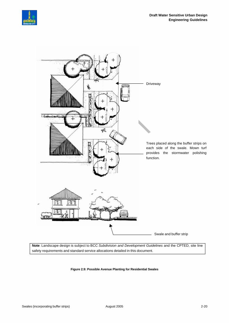
Figure 2.9: Possible Avenue Planting for Residential Swales
Driveway
Trees placed along the buffer strips oneach side of the swale. Mown turfprovides the stormwater polishingfunction.
Swale and buffer strip
Note: Landscape design is subject to BCC Subdivision and Development Guidelines and the CPTED, site linesafety requirements and standard service allocations detailed in this document.