Embed Size (px)
Citation preview
LG AHU Control Kit / EEV Kit Installation Manual
LG
IMPORTANT
• Please read this installation manual completely before installing the product.
• Installation work must be performed in accordance with the national wiring standards by authorized personnel only.
• Please retain this installation manual for future reference after reading it thoroughly.
Visit us at : http://www.lgservice.com
Models: PRCKA0PRLK048A0
ENG
LISH
2 AHU Control Kit / EEV Kit
AHU Control Kit / EEV Kit Installation Manual
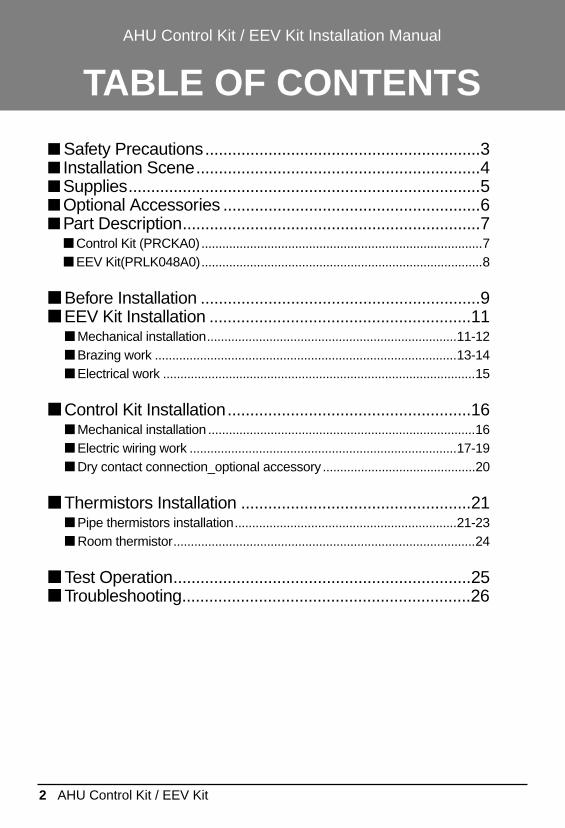
TABLE OF CONTENTS
■ Safety Precautions.............................................................3■ Installation Scene...............................................................4■ Supplies..............................................................................5■ Optional Accessories .........................................................6■ Part Description..................................................................7
■ Control Kit (PRCKA0).................................................................................7■ EEV Kit(PRLK048A0).................................................................................8
■ Before Installation ..............................................................9■ EEV Kit Installation ..........................................................11
■ Mechanical installation........................................................................11-12■ Brazing work .......................................................................................13-14■ Electrical work ..........................................................................................15
■ Control Kit Installation......................................................16■ Mechanical installation .............................................................................16■ Electric wiring work .............................................................................17-19■ Dry contact connection_optional accessory ............................................20
■ Thermistors Installation ...................................................21■ Pipe thermistors installation................................................................21-23■ Room thermistor.......................................................................................24
■ Test Operation..................................................................25■ Troubleshooting................................................................26
Safety Precautions
Installation Manual 3
ENG
LISH
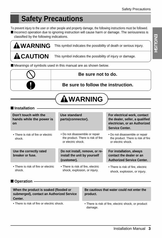
■ Installation
Safety PrecautionsTo prevent injury to the user or other people and property damage, the following instructions must be followed.■ Incorrect operation due to ignoring instruction will cause harm or damage. The seriousness is
classified by the following indications.
■ Meanings of symbols used in this manual are as shown below.
WARNING
CAUTION
This symbol indicates the possibility of death or serious injury.
This symbol indicates the possibility of injury or damage.
Be sure not to do.
Be sure to follow the instruction.
WARNING
When the product is soaked (flooded orsubmerged), contact an Authorized ServiceCenter.• There is risk of fire or electric shock.
Be cautious that water could not enter theproduct.
• There is risk of fire, electric shock, or productdamage.
■ Operation
Use the correctly ratedbreaker or fuse.
• There is risk of fire or electricshock.
Do not install, remove, or re-install the unit by yourself(customer).
• There is risk of fire, electricshock, explosion, or injury.
For installation, alwayscontact the dealer or anAuthorized Service Center.
• There is risk of fire, electric
shock, explosion, or injury.
Don't touch with thehands while the power ison
• There is risk of fire or electricshock.
Use standardparts(connector).
• Do not disassemble or repairthe product. There is risk of fireor electric shock.
For electrical work, contactthe dealer, seller, a qualifiedelectrician, or an AuthorizedService Center.
• Do not disassemble or repairthe product. There is risk of fireor electric shock.
4 AHU Control Kit / EEV Kit
Installation Scene
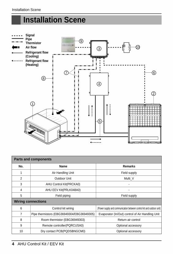
Installation Scene
SignalPipeThermistor
10
6
8
9
7
2
4
3
1
5
Air flowRefrigerant flow(Cooling) Refrigerant flow(Heating)
1
2
3
4
5
Air Handling Unit
Outdoor Unit
AHU Control Kit(PRCKA0)
AHU EEV Kit(PRLK048A0)
Field piping
Field supply
Multi_V
-
-
Field supply
Parts and components
6
7
8
9
10
Control kit wiring
Pipe thermistors (EBG36949304/EBG36949305)
Room thermistor (EBG36949303)
Remote controller(PQRCUSA0)
Dry contact PCB(PQDSBNGCM0)
(Power supply and communication between control kit and outdoor unit)
Evaporator (In/Out) control of Air Handling Unit
Return air control
Optional accessory
Optional accessory
Wiring connections
No. Name Remarks
Installation Manual 5
ENG
LISHSupplies
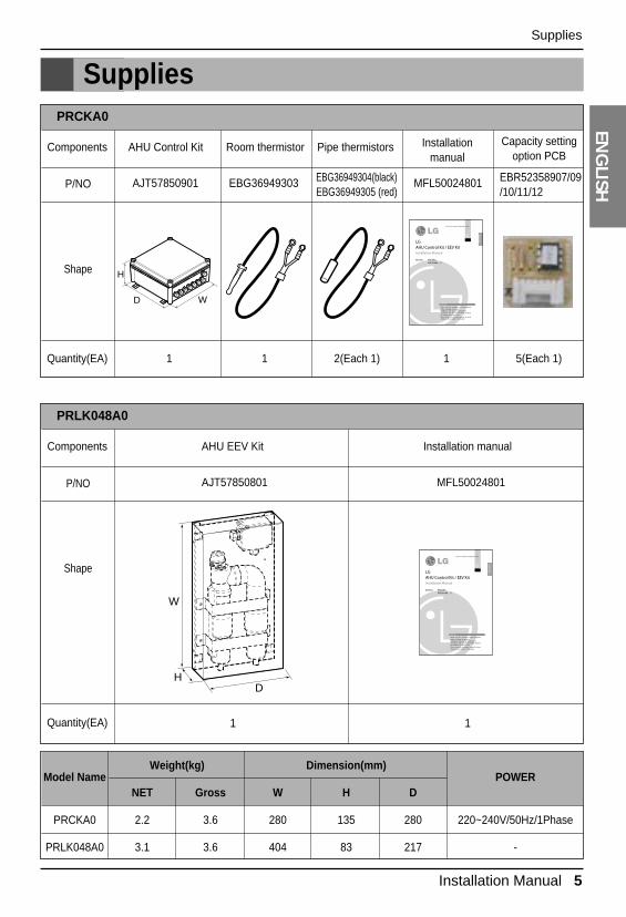
Supplies
Components
Quantity(EA) 1 1 2(Each 1) 1 5(Each 1)
AHU Control Kit Room thermistor Pipe thermistors Installationmanual
Capacity settingoption PCB
AJT57850901 EBG36949303 EBG36949304(black)EBG36949305 (red)
MFL50024801 EBR52358907/09/10/11/12
P/NO
Shape
PRCKA0
WD
H
Components
Quantity(EA) 1 1
AHU EEV Kit Installation manual
AJT57850801 MFL50024801P/NO
Shape
PRLK048A0
W
DH
Model NameWeight(kg) Dimension(mm)
POWERNET Gross W H D
PRCKA0 2.2 3.6 280 135 280 220~240V/50Hz/1Phase
PRLK048A0 3.1 3.6 404 83 217 -
6 AHU Control Kit / EEV Kit
Optional Accessories
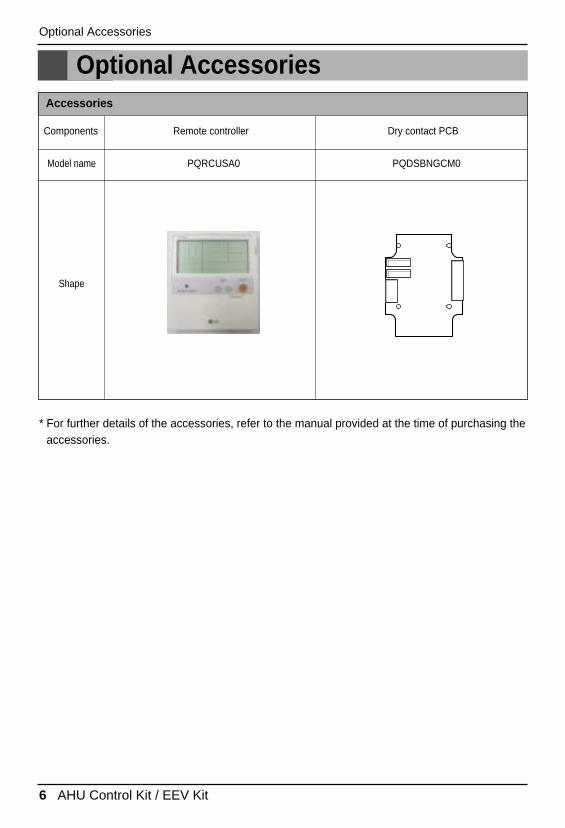
Optional Accessories
Components Remote controller Dry contact PCB
PQRCUSA0 PQDSBNGCM0Model name
Shape
Accessories
* For further details of the accessories, refer to the manual provided at the time of purchasing theaccessories.
Installation Manual 7
ENG
LISHPart Description
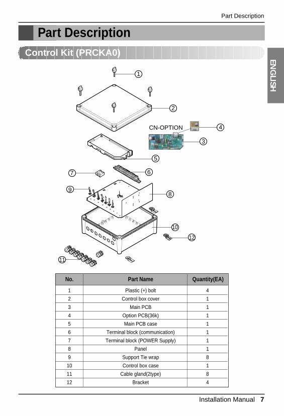
Part DescriptionControl Kit (PRCKA0)
1
2
3
4
5
7
11
98
10
12
6
CN-OPTION
1
2
3
4
5
6
7
8
9
10
11
12
Plastic (+) bolt
Control box cover
Main PCB
Option PCB(36k)
Main PCB case
Terminal block (communication)
Terminal block (POWER Supply)
Panel
Support Tie wrap
Control box case
Cable gland(2type)
Bracket
4
1
1
1
1
1
1
1
8
1
8
4
No. Part Name Quantity(EA)
8 AHU Control Kit / EEV Kit
Part Description
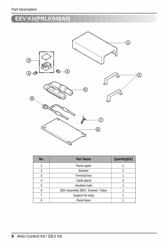
EEV Kit(PRLK048A0)
1
2
5
3
4 4
8
7
6
1
2
3
4
5
6
7
8
Panel upper
Bracket
Terminal box
Cable gland
Insulator tube
EEV assembly (EEV, Strainer, Tube)
Support tie wrap
Panel base
1
2
1
2
1
1
1
1
No. Part Name Quantity(EA)
Installation Manual 9
ENG
LISHBefore Installation
Before Installation
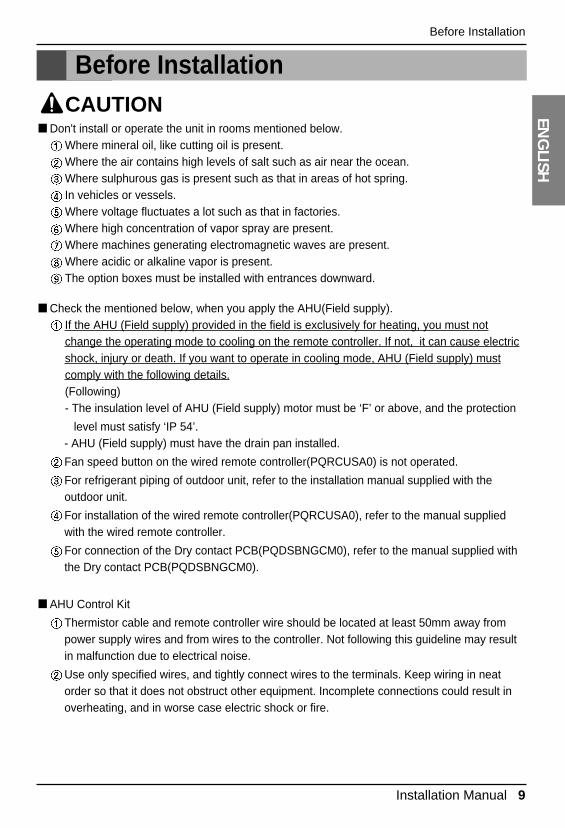
■ Don't install or operate the unit in rooms mentioned below.Where mineral oil, like cutting oil is present.Where the air contains high levels of salt such as air near the ocean.Where sulphurous gas is present such as that in areas of hot spring.In vehicles or vessels.Where voltage fluctuates a lot such as that in factories.Where high concentration of vapor spray are present.Where machines generating electromagnetic waves are present.Where acidic or alkaline vapor is present.The option boxes must be installed with entrances downward.
CAUTION
■ Check the mentioned below, when you apply the AHU(Field supply).If the AHU (Field supply) provided in the field is exclusively for heating, you must notchange the operating mode to cooling on the remote controller. If not, it can cause electricshock, injury or death. If you want to operate in cooling mode, AHU (Field supply) mustcomply with the following details.(Following)- The insulation level of AHU (Field supply) motor must be ‘F’ or above, and the protection
level must satisfy ‘IP 54’.- AHU (Field supply) must have the drain pan installed.
Fan speed button on the wired remote controller(PQRCUSA0) is not operated.
For refrigerant piping of outdoor unit, refer to the installation manual supplied with theoutdoor unit.
For installation of the wired remote controller(PQRCUSA0), refer to the manual suppliedwith the wired remote controller.
For connection of the Dry contact PCB(PQDSBNGCM0), refer to the manual supplied withthe Dry contact PCB(PQDSBNGCM0).
■ AHU Control Kit
Thermistor cable and remote controller wire should be located at least 50mm away frompower supply wires and from wires to the controller. Not following this guideline may resultin malfunction due to electrical noise.
Use only specified wires, and tightly connect wires to the terminals. Keep wiring in neatorder so that it does not obstruct other equipment. Incomplete connections could result inoverheating, and in worse case electric shock or fire.
10 AHU Control Kit / EEV Kit
Before Installation
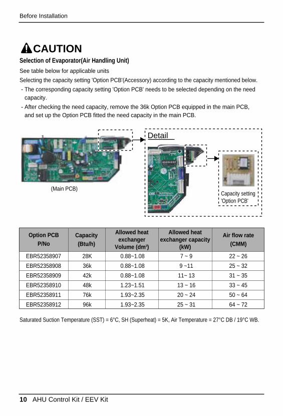
Selection of Evaporator(Air Handling Unit)
See table below for applicable units
Selecting the capacity setting 'Option PCB'(Accessory) according to the capacity mentioned below.
- The corresponding capacity setting 'Option PCB' needs to be selected depending on the needcapacity.
- After checking the need capacity, remove the 36k Option PCB equipped in the main PCB, and set up the Option PCB fitted the need capacity in the main PCB.
CAUTION
Saturated Suction Temperature (SST) = 6°C, SH (Superheat) = 5K, Air Temperature = 27°C DB / 19°C WB.
(Main PCB)
EBR52358907 28K 0.88~1.08 7 ~ 9 22 ~ 26
EBR52358908 36k 0.88~1.08 9 ~11 25 ~ 32
EBR52358909 42k 0.88~1.08 11~ 13 31 ~ 35
EBR52358910 48k 1.23~1.51 13 ~ 16 33 ~ 45
EBR52358911 76k 1.93~2.35 20 ~ 24 50 ~ 64
EBR52358912 96k 1.93~2.35 25 ~ 31 64 ~ 72
Option PCBP/No
Capacity(Btu/h)
Allowed heatexchanger
Volume (dm3)
Allowed heatexchanger capacity
(kW)
Air flow rate(CMM)
Capacity setting 'Option PCB'
Detail
Installation Manual 11
ENG
LISHEEV Kit Installation
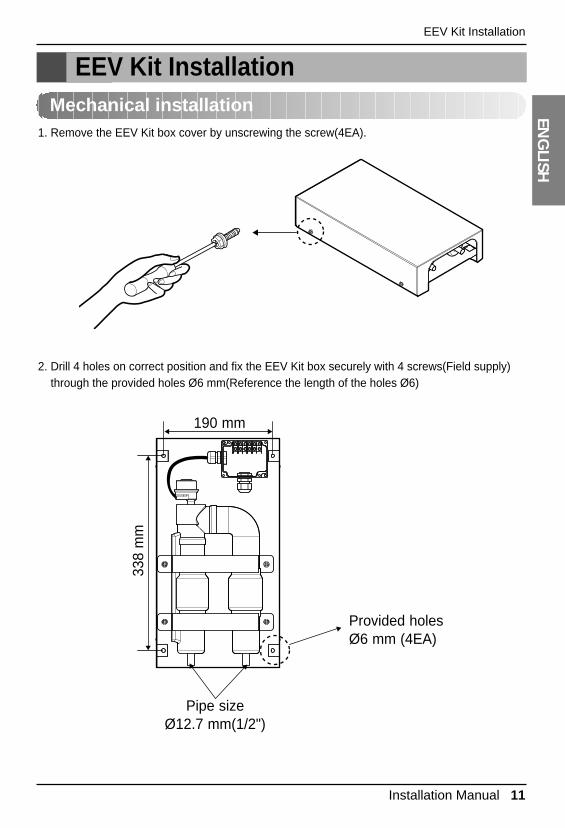
EEV Kit InstallationMechanical installation
1. Remove the EEV Kit box cover by unscrewing the screw(4EA).
2. Drill 4 holes on correct position and fix the EEV Kit box securely with 4 screws(Field supply)through the provided holes Ø6 mm(Reference the length of the holes Ø6)
190 mm
Provided holesØ6 mm (4EA)
Pipe sizeØ12.7 mm(1/2")
338
mm
12 AHU Control Kit / EEV Kit
EEV Kit Installation
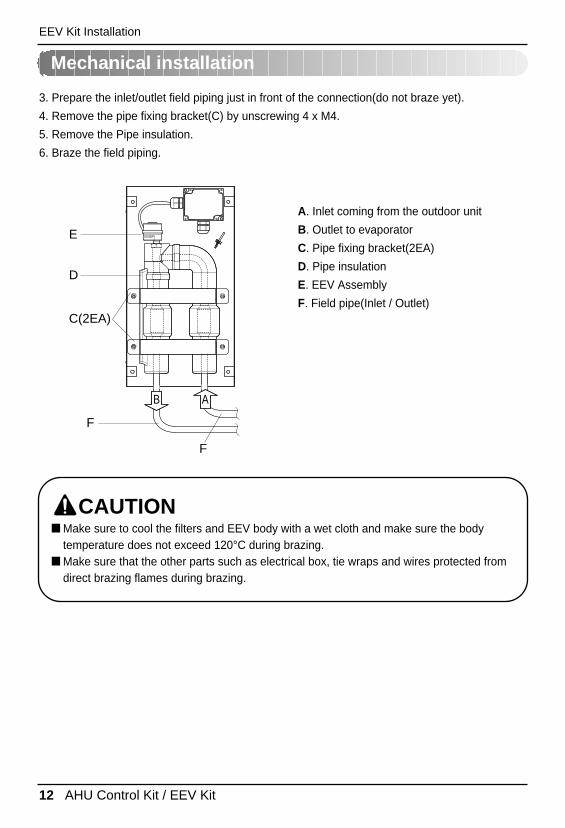
3. Prepare the inlet/outlet field piping just in front of the connection(do not braze yet).
4. Remove the pipe fixing bracket(C) by unscrewing 4 x M4.
5. Remove the Pipe insulation.
6. Braze the field piping.
A. Inlet coming from the outdoor unit
B. Outlet to evaporator
C. Pipe fixing bracket(2EA)
D. Pipe insulation
E. EEV Assembly
F. Field pipe(Inlet / Outlet)
E
D
C(2EA)
F
F
B A
■ Make sure to cool the filters and EEV body with a wet cloth and make sure the bodytemperature does not exceed 120°C during brazing.
■ Make sure that the other parts such as electrical box, tie wraps and wires protected fromdirect brazing flames during brazing.
CAUTION
Mechanical installation
Installation Manual 13
ENG
LISHEEV Kit Installation
Brazing work
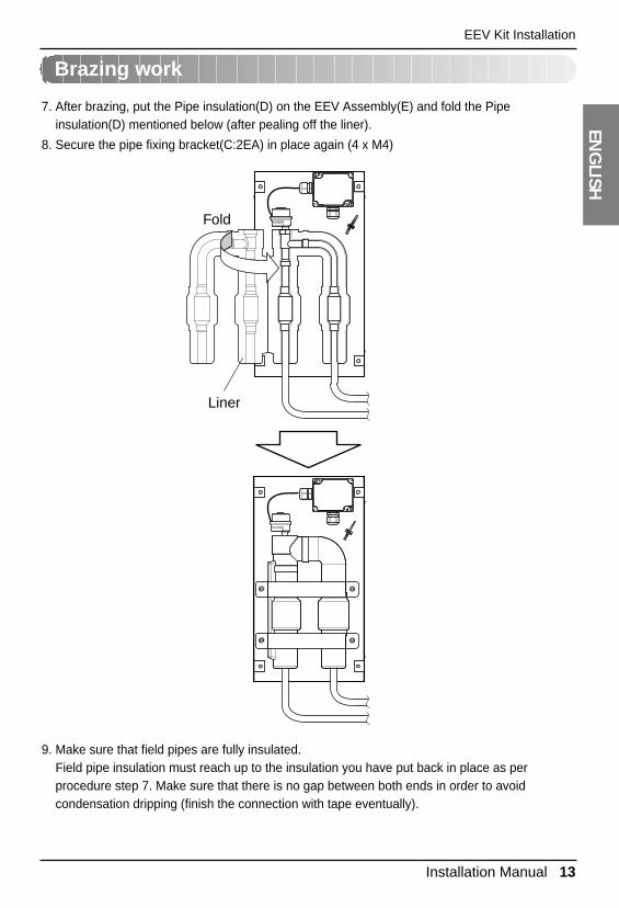
7. After brazing, put the Pipe insulation(D) on the EEV Assembly(E) and fold the Pipeinsulation(D) mentioned below (after pealing off the liner).
8. Secure the pipe fixing bracket(C:2EA) in place again (4 x M4)
9. Make sure that field pipes are fully insulated.Field pipe insulation must reach up to the insulation you have put back in place as perprocedure step 7. Make sure that there is no gap between both ends in order to avoidcondensation dripping (finish the connection with tape eventually).
Liner
Fold
14 AHU Control Kit / EEV Kit
a b cd
f
brazing
e
f
EEV Kit Installation
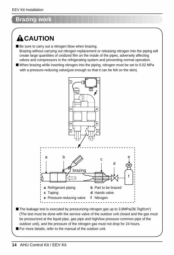
■ Be sure to carry out a nitrogen blow when brazing.Brazing without carrying out nitrogen replacement or releasing nitrogen into the piping willcreate large quantities of oxidized film on the inside of the pipes, adversely affectingvalves and compressors in the refrigerating system and preventing normal operation.
■ When brazing while inserting nitrogen into the piping, nitrogen must be set to 0.02 MPa with a pressure-reducing valve(just enough so that it can be felt on the skin).
CAUTION
■ The leakage test is executed by pressurizing nitrogen gas up to 3.8MPa(38.7kgf/cm2)(The test must be done with the service valve of the outdoor unit closed and the gas mustbe pressurized at the liquid pipe, gas pipe and high/low pressure common pipe of theoutdoor unit), and the pressure of the nitrogen gas must not drop for 24 hours.
■ For more details, refer to the manual of the outdoor unit.
a Refrigerant piping b Part to be brazedc Taping d Hands valvee Pressure-reducing valve f Nitrogen
Brazing work
Installation Manual 15
ENG
LISHEEV Kit Installation
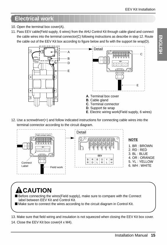
Electrical work10. Open the terminal box cover(A).11. Pass EEV cable(Field supply, 6 wires) from the AHU Control Kit through cable gland and connect
the cable wires into the terminal connector(C) following instructions as describe in step 12. Routethe cable out of the EEV Kit box according to figure below and fix with the support tie wrap(D).
A. Terminal box coverB. Cable glandC. Terminal connectorD. Support tie wrapE. Electric wiring work(Field supply, 6 wires)
NOTE
1. BR : BROWN2. RD : RED3. BL : BLUE4. OR : ORANGE5. YL : YELLOW6. WH : WHITE
A
BD
E
BR
RD
BL
OR
YL
WH
EEV
C
Detail
E
12. Use a screwdriver(+) and follow indicated instructions for connecting cable wires into theterminal connector according to the circuit diagram.
13. Make sure that field wiring and insulation is not squeezed when closing the EEV Kit box cover.
14. Close the EEV Kit box cover(4 x M4).
BR
RD
BL
OR
YL
WH
EEV
Field work
Field connect wires
ConnectLabel
BR
RD
BL
OR
YL
WH
EEV
Detail
■ Before connecting the wires(Field supply), make sure to compare with the Connect label between EEV Kit and Control Kit.
■ Make sure to connect the wires according to the circuit diagram in Control Kit.
CAUTION
16 AHU Control Kit / EEV Kit
Control Kit Installation
Control Kit InstallationMechanical installation
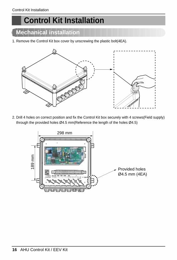
1. Remove the Control Kit box cover by unscrewing the plastic bolt(4EA).
2. Drill 4 holes on correct position and fix the Control Kit box securely with 4 screws(Field supply)through the provided holes Ø4.5 mm(Reference the length of the holes Ø4.5)
298 mm
Provided holesØ4.5 mm (4EA)
189
mm
Installation Manual 17
ENG
LISHControl Kit Installation
Electric Wiring Work
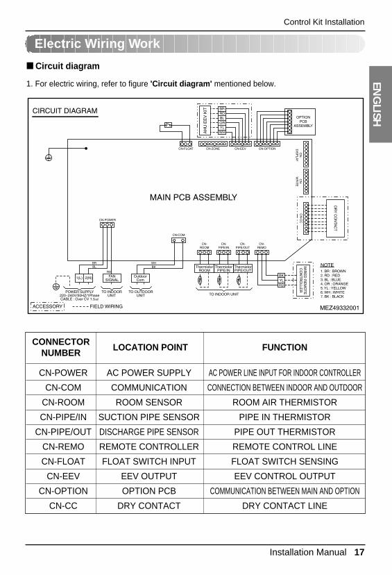
1. For electric wiring, refer to figure 'Circuit diagram' mentioned below.
■ Circuit diagram
CN-POWER AC POWER SUPPLY AC POWER LINE INPUT FOR INDOOR CONTROLLER
CN-COM COMMUNICATION CONNECTION BETWEEN INDOOR AND OUTDOOR
CN-ROOM ROOM SENSOR ROOM AIR THERMISTOR
CN-PIPE/IN SUCTION PIPE SENSOR PIPE IN THERMISTOR
CN-PIPE/OUT DISCHARGE PIPE SENSOR PIPE OUT THERMISTOR
CN-REMO REMOTE CONTROLLER REMOTE CONTROL LINE
CN-FLOAT FLOAT SWITCH INPUT FLOAT SWITCH SENSING
CN-EEV EEV OUTPUT EEV CONTROL OUTPUT
CN-OPTION OPTION PCB COMMUNICATION BETWEEN MAIN AND OPTION
CN-CC DRY CONTACT DRY CONTACT LINE
LOCATION POINT FUNCTIONCONNECTOR
NUMBER
18 AHU Control Kit / EEV Kit
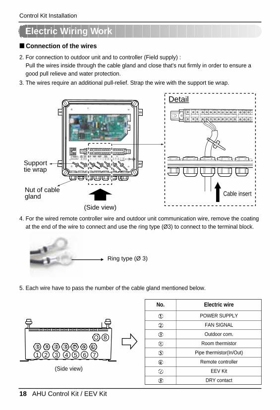
4. For the wired remote controller wire and outdoor unit communication wire, remove the coatingat the end of the wire to connect and use the ring type (Ø3) to connect to the terminal block.
Ring type (Ø 3)
1 2 3 4 5 6 7
8
POWER SUPPLY
FAN SIGNAL
Outdoor com.
Room thermistor
Pipe thermistor(In/Out)
Remote controller
EEV Kit
DRY contact
No. Electric wire
Control Kit Installation
Electric Wiring Work
2. For connection to outdoor unit and to controller (Field supply) : Pull the wires inside through the cable gland and close that's nut firmly in order to ensure agood pull relieve and water protection.
3. The wires require an additional pull-relief. Strap the wire with the support tie wrap.
Supporttie wrap
Nut of cable gland
(Side view)
Detail
Cable insert
5. Each wire have to pass the number of the cable gland mentioned below.
(Side view)
■ Connection of the wires
Installation Manual 19
ENG
LISHControl Kit Installation
Electric Wiring Work
■ All field supplied parts and materials and electric works must be conform to local codes.■ Use copper wire only.■ All wiring must be performed by an authorized electrician.■ A main switch or other means for disconnection, having a contact separation in all poles,
must be incorporated in the fixed wiring in accordance with relevant local and nationallegislation.
■ Refer to the installation manual attached to the outdoor unit for the size of power supplyelectric wire connected to the outdoor unit, the capacity of the circuit breaker and switch,wiring and wiring instructions.
CAUTION
20 AHU Control Kit / EEV Kit
Control Kit Installation
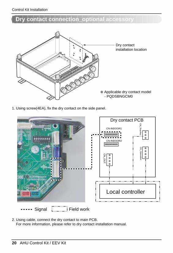
Dry contact connection_optional accessory
Local controller
CN-INDOOR1
CN-INDOOR2
CD
_Operation
CN
_OU
T
Dry Contact PCBDry Contact PCB
Dry contact PCB
Signal
CN
_Ther/P
er
Field work
Dry contactinstallation location
❈ Applicable dry contact model - PQDSBNGCM0
1. Using screw(4EA), fix the dry contact on the side panel.
2. Using cable, connect the dry contact to main PCB.For more information, please refer to dry contact installation manual.
Installation Manual 21
ENG
LISHThermistors Installation
Pipe thermistors Installation
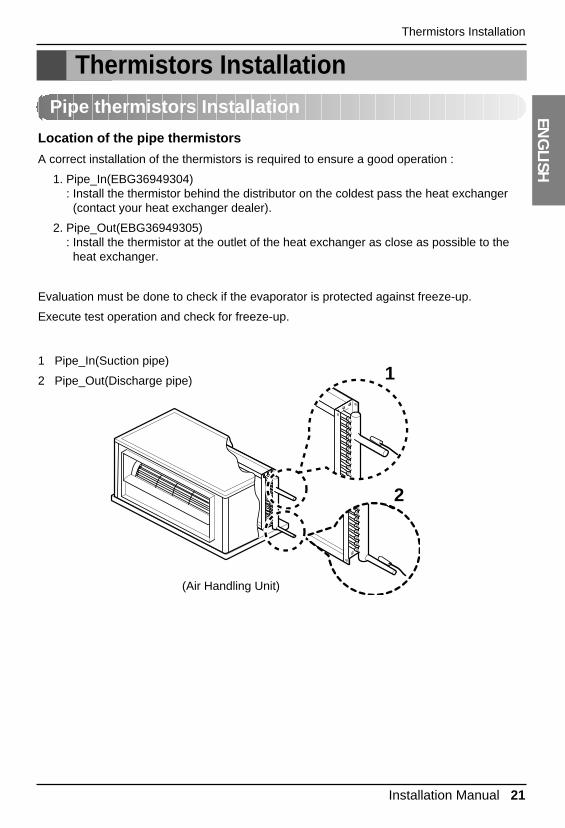
Location of the pipe thermistors
A correct installation of the thermistors is required to ensure a good operation :
1. Pipe_In(EBG36949304): Install the thermistor behind the distributor on the coldest pass the heat exchanger(contact your heat exchanger dealer).
2. Pipe_Out(EBG36949305): Install the thermistor at the outlet of the heat exchanger as close as possible to theheat exchanger.
Evaluation must be done to check if the evaporator is protected against freeze-up.
Execute test operation and check for freeze-up.
1 Pipe_In(Suction pipe)
2 Pipe_Out(Discharge pipe)
(Air Handling Unit)
1
2
Thermistors Installation
22 AHU Control Kit / EEV Kit
Thermistors Installation
Pipe thermistors Installation
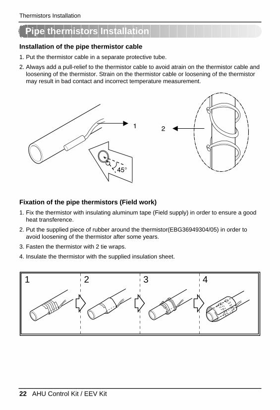
Installation of the pipe thermistor cable
1. Put the thermistor cable in a separate protective tube.
2. Always add a pull-relief to the thermistor cable to avoid atrain on the thermistor cable andloosening of the thermistor. Strain on the thermistor cable or loosening of the thermistormay result in bad contact and incorrect temperature measurement.
2
45°
1
Fixation of the pipe thermistors (Field work)
1. Fix the thermistor with insulating aluminum tape (Field supply) in order to ensure a goodheat transference.
2. Put the supplied piece of rubber around the thermistor(EBG36949304/05) in order toavoid loosening of the thermistor after some years.
3. Fasten the thermistor with 2 tie wraps.
4. Insulate the thermistor with the supplied insulation sheet.
1 2 3 4
Installation Manual 23
ENG
LISHThermistors Installation
Fixation of the pipe thermistors (Field work)
1. Fix the thermistor with insulating aluminum tape (Field supply) in order to ensure a goodheat transference.
2. Put the supplied piece of rubber around the thermistor(EBG36949304/05) in order toavoid loosening of the thermistor after some years.
3. Fasten the thermistor with 2 tie wraps.
4. Insulate the thermistor with the supplied insulation sheet.
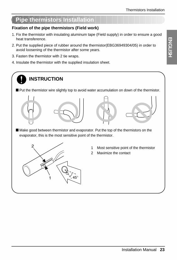
INSTRUCTION
■ Put the thermistor wire slightly top to avoid water accumulation on down of the thermistor.
■ Make good between thermistor and evaporator. Put the top of the thermistors on theevaporator, this is the most sensitive point of the thermistor.
1 Most sensitive point of the thermistor2 Maximize the contact
45°
2
1
Pipe thermistors Installation
24 AHU Control Kit / EEV Kit
Thermistors Installation
Room thermistor
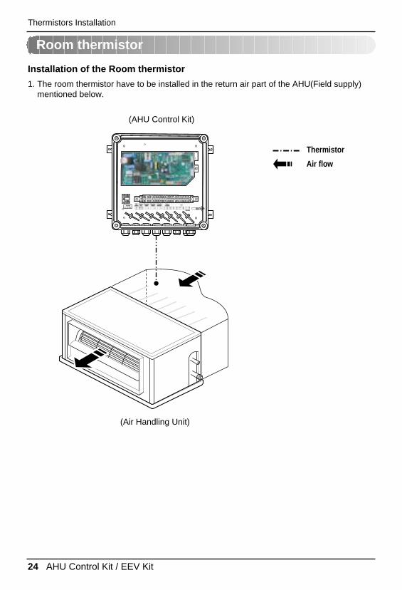
Installation of the Room thermistor
1. The room thermistor have to be installed in the return air part of the AHU(Field supply)mentioned below.
Thermistor
Air flow
(Air Handling Unit)
(AHU Control Kit)
Installation Manual 25
ENG
LISHTest Operation
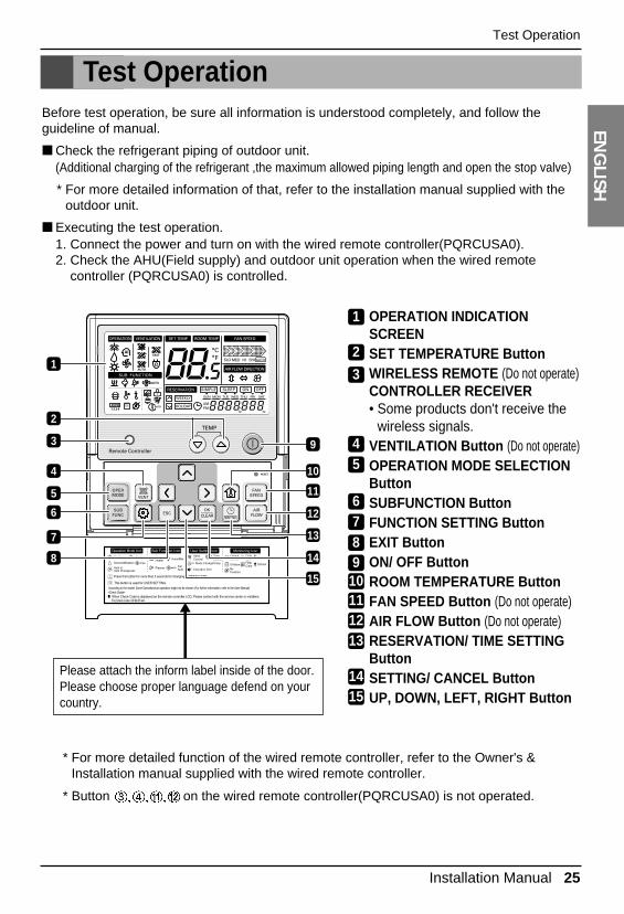
Test OperationBefore test operation, be sure all information is understood completely, and follow theguideline of manual.
■ Check the refrigerant piping of outdoor unit.(Additional charging of the refrigerant ,the maximum allowed piping length and open the stop valve)
* For more detailed information of that, refer to the installation manual supplied with theoutdoor unit.
■ Executing the test operation.1. Connect the power and turn on with the wired remote controller(PQRCUSA0).2. Check the AHU(Field supply) and outdoor unit operation when the wired remote
controller (PQRCUSA0) is controlled.
* For more detailed function of the wired remote controller, refer to the Owner's &Installation manual supplied with the wired remote controller.
* Button on the wired remote controller(PQRCUSA0) is not operated.
OPERATION INDICATIONSCREENSET TEMPERATURE ButtonWIRELESS REMOTE (Do not operate)CONTROLLER RECEIVER• Some products don't receive the
wireless signals. VENTILATION Button (Do not operate)OPERATION MODE SELECTIONButtonSUBFUNCTION ButtonFUNCTION SETTING ButtonEXIT ButtonON/ OFF ButtonROOM TEMPERATURE ButtonFAN SPEED Button (Do not operate)AIR FLOW Button (Do not operate)RESERVATION/ TIME SETTINGButtonSETTING/ CANCEL ButtonUP, DOWN, LEFT, RIGHT Button
1
9
11
12
3
5
6
2
4 10
13
14
7
8
15
Please attach the inform label inside of the door.Please choose proper language defend on your country.
1
2
3
45
6789
10111213
1415
26 AHU Control Kit / EEV Kit
Troubleshooting
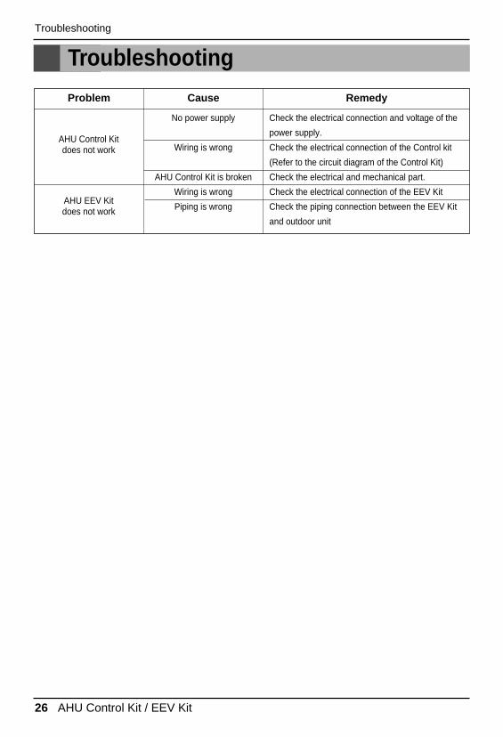
Troubleshooting
AHU Control Kit does not work
AHU EEV Kitdoes not work
No power supply Check the electrical connection and voltage of the
power supply.
Wiring is wrong Check the electrical connection of the Control kit
(Refer to the circuit diagram of the Control Kit)
AHU Control Kit is broken Check the electrical and mechanical part.
Wiring is wrong Check the electrical connection of the EEV Kit
Piping is wrong Check the piping connection between the EEV Kit
and outdoor unit
Problem Cause Remedy

P/No.: MFL50024801After reading this manual, keep it in a place easily accessible to the user for future reference.
Printed in Korea
![HU +] for Europe + 3 + 5 · AHU KIT EEV KIT Y-Joint Y-Joint Outdoor unit Distribution Header Y-Joint (Only H/R) Y-Joint (Only H/R) Outdoor unit MCU Accessory R. Product Image Model](https://img.pdfslide.us/doc/110x75/5e4edd5e16ad6f336d5a56c2/hu-for-europe-3-5-ahu-kit-eev-kit-y-joint-y-joint-outdoor-unit-distribution.jpg)