Embed Size (px)
Citation preview

RsfereBoe
DEPARTMENT OF THE ARMY 1 \ F I E L D MANUAL w s s" fefcftöfl DEPARTMENT OF THE
AIR FORCE MANUAL
FM 5-35
AFM 88-54
ENGINEERS, REFERENCE AND
LOGISTICAL DATA
\
•fEs
w;
Fti
DEPARTMENTS OF THE ARMY AND THE AIR FORCE FEBRUARY 1960
\


ACKNOWLEDGMENTS
Acknowledgment is gratefully made to the authors and publishers listed below for their permission to use in this manual the copyrighted material indicated:
Table 176, National Design Specification for Stress-Grade Lumber and its Fastenings, revised 1955, from National Lumber Manufactur- ers Association.
Table 172, Tentative Specifications for Billet-Steel Bars for Concrete Reinforcement, A.S.T.M. Designation A15-58T, revised February 1959, from American Society for Testing Materials.
Table 175, Manual of Structural Design, Third Edition, pages 8 through 33, from H. M. Ives and Sons, by J. Singleton.
Tables 146, 150 through 154, from Steel Construction, Fifth Edition, from American Institute of Steel Construction, copyrighted 1947.
Table 97, Guide to Horsepower Limits of Individual Motors for Different Systems, page 999, American Electricians’ Handbook, 1953 edition, from McGraw-Hill Book Company, Inc.
Portions of paragraph 165 and 169, Tables 171 and 187, from American Concrete Institute, May 1956, paragraph 506 and 1303. Building Code Requirements for Reinforced Concrete, 5th printing pages 22 and 23; formula 30 on page 96; Table 9 on page 52; diagram 17 on page 58 and Table 15 on page 57 of the Reinforced Concrete Design Handbook, 2d edition, from American Concrete Institute.
Figure 46, from Section 20, page 311, Nomogram for Calculating Pipe Size, discharge and head loss, American Pipe Manual, from American Cast Iron Pipe Company.
Figure 58, from Audels New Electric Library, by Frank D. Graham, Theo Audel and Co., Publishers.
Figures 72 and 74, from Architects and Builders Handbook, by Kidder and Parker.
Figure 68, from Architectural Graphic Standards, by Ramsey and Sleeper.
Figure 6, from Data Book for Civil Engineers—Design 1945 edition, by Elwyn E. Seelye.
Figures 84 through 93 and Tables 183, 184 and paragraph 177e(2), from Modern Timber Design, by Howard J. Hansen. In addition, certain other material, as indicated throughout the
manual, through permission of McGraw-Hill Book Co., Inc.; John Wiley and Sons, Inc.; H. M. Ives and Sons; the American Institute of Steel Construction; and National Fire Protection Association.
i


This manual contains copyrighted material
ARMY FIELD MANUAL'
No. 5-35 AIR FORCE MANUAL
No. 88-54
*FM 5-35/AFM 88-54
DEPARTMENTS OF THE ARMY AND THE AIR FORCE
WASHINGTON 25, D.C., 28 February 1960
ENGINEERS’ REFERENCE AND LOGISTICAL DATA
CHAPTER 1.
2.
3.
Section I.
II.
III.
IV. V.
VI.
CHAPTER 4.
5.
Section I.
II.
III.
IV.
CHAPTER 6.
Section I.
II.
III.
CHAPTER 7.
CHAPTER 8.
Section I.
II.
III.
IV.
V.
CHAPTER
Section I.
II.
II.
IV V.
Paragraphs Page
INTRODUCTION 1-3 3
ENGINEER TROOPS 4-5 4
LOGISTICAL DATA
Equipment other than motorized 6-8 32
Motorized and heavy equipment 9-14 57 USAF aircraft and airfield data 15-18 79
U.S. Army aircraft and airfield data 19-21 87
Railroad data 22-28 94
Special data 29-32 107
PRISONER-OF-WAR INCLOSURES 33-36 128
FORTIFICATIONS AND CAMOUFLAGE
General 37, 38 135
Cover and shelter 39-44 136
Obstacles 45—47 140
Camouflage 48-51 152
ROADS AND BRIDGES Militarj' roads 52-56 169
Stream crossing equipment 57—65 189
Cableways and tramways 66-67 201
NAVY PONTOON GEAR 68-74 207
UTILITIES
Water supply and distribution 75-95 215
Sewerage 96-107 254
Refuse collection and disposal 108-114 263
Electric-power distribution 115-131 267
Special utilities 132-138 328
STRUCTURAL DESIGN DATA
Design loads 139-145 336
Design formulas 146-148 352
Structural steel 149-163 368
Reinforced concrete 164-172 412 Timber 173-177 437
This manual supersedes FM 5-35/AFM 88-54, 4 September 1952.
1

CHAPTER 10. ¡MATERIALS OF CONSTRUCTION Paragraphs Page
Section I. Wood 178-179 465 II. Steel products 180-184 468
III. Concrete and concrete materials 185-187 477 IV. Bituminous construction materials 188-190 487
V. Soils 191-194 492 VI. Miscellaneous building materials and hardware 195-202 492
VII. Masonry 203-207 511 VIII. Explosives 208-211 513
CHAPTER 11. MISCELLANEOUS DATA Section I. Mathematical data 212-214 517
II. Physical data 215-228 522 APPENDIX I. REFERENCES 569 INDEX 571
2

CHAPTER !
INTRODUCTION
1. Purpose This manual is intended to provide engineer and other military per-
sonnel at all levels, including operations and planning officers, with a compilation of data for use as a guide in the logistical planning of engineer activities.
2. Scope a. The manual includes logistical data pertaining to engineer troops,
equipment, materials, and installations, and to all types of engineer activities, including fortifications, camouflage, roads, railroads, bridges, airfields, utilities, and general construction. It also contains mis- cellaneous physical and mathematical data and conversion tables.
b. The material presented heroin is applicable without modification to both nuclear and non-nuclear warfare.
3. Relation to Other Manuals Various manuals of the FM 5-, TM 5-, and AFM 88-series con-
tain detailed logistical data on the above topics, and on individual items of engineer equipment in temperate climates. This manual is confined to summarizing such information and stating what sources should be consulted for further details.
3
CHAPTER 2
ENGINEER TROOPS
4. General FM 5-5 sets forth the mission, assignments, capabilities, organiza-
tion, and normal employment of all engineer troop units. The TOE’s for these units give further personnel and equipment details.
5. Strength oí Engineer Units The tabulation in table 1 gives basic data on engineer troop units;
that in table 2, on engineer teams listed in TOE 5-500C. The data is subject to change and the latest appropriate TOE list should also be consulted.
4

Table 1. Engineer Troop Units
TOE No.
5-301
5-15
5-16
5-17
5-35
Unit Authorized strength
Ofl WO EM Total
Normal assignment Mission, capabilities, and remarks
ENGINEER COMMAND
UNITS
Headquarters and head- quarters company, engineer brigade.
ENGINEER COMBAT UNITS
Infantry division engi- neer battalion.
Headquarters and head- quarters company, infantry division engineer battalion.
Engineer company, in- fantry division, engineer battalion.
Engineer combat bat- talion, army.
29 107 142
42
22
739
224
785
250
30
103
586
107
619
Communications zone, task force, army, or high headquarters.
Infantry division.
1 per battalion.
5 per battalion.
3 per engineer combat group.
Commands engineer units totaling 9,000 to 15,000 men.
Provides general engineer support for infantry division. Combat com- panies can operate independently.
Provides division engineer special staff and command staff, communi- cation, reconnaissance, supply, maintenance, and supplemental heavy equipment for the infantry division engineer battalion.
Provides general engineer support for infantry division. Combat com- panies can operate independently.
As component of engineer combat group, provides general engineer support for a corps or army. Com- bat battalions can operate inde- pendently.
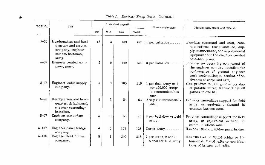
Table 1. Engineer Troop Units—Continued
TOE No.
5-36
5-37
5-67
5-96
5-97
5-137
5-138
Unit
Headquarters and head- quarters and service company, engineer combat battalion, army.
Engineer combat com- pany, army.
Engineer water supply company.
Headquarters and head- quarters detachment, engineer camouflage battalion.
Engineer camouflage company.
Engineer panel bridge company.
Engineer float bridge company.
Authorized strength
Oft WO
15
EM
139
149
105
54
65
124
209
Total
157
154
110
63
70
128
218
Normal assignment
1 per battalion.
3 per battalion.
1 per field army or 1 per 400,000 troops in communications zone.
Army communications zone.
3 per battalion or field army.
Corps, army.
2 per corps, 9 addi- tional for field army.
Mission, capabilities, and remarks
Provides command and staff, com- munications, reconnaissance, sup- ply, maintenance, and supplemental equipment for the engineer combat battalion, army.
Provides an operating component of the engineer combat battalion for performance of general engineer work contributing to combat effec- tiveness of corps and army.
Can produce 27,000 gallons per day of potable water; transport 18,000 gallons in one lift.
Provides camouflage support for field army, or equivalent demand in communications zone.
Provides camouflage support for field army, or equivalent demand in communications zone.
Has one 130-foot, 40-ton panel bridge.
Has 700 feet of M4T6 bridge or 10- four-float M4T6 rafts or combina- tions of bridges and rafts.
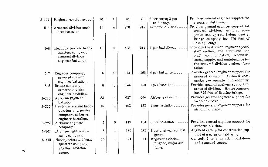
5-192
5-5
5-6
5-7
5-8
5-225
5-226
5-227
5-367
5-412
Engineer combat group. 16 1
Armored division engi- 41 4 neer battalion.
Headquarters and head- 19 quarters company, armored division engineer battalion.
Engineer company, armored division engineer battalion.
Bridge company, armored division engineer battalion.
Airborne engineer 33 battalion.
Headquarters and head- 16 quarters and service company, airborne engineer battalion.
Airborne engineer 5 company.
Engineer light equip- 5 ment company.
Headquarters and head- 15 quarters company, engineer aviation group.
4
4
0
1
5
64
870
188
161
144
627
163
149
180
91
81
915
211
2 per corps; 3 per field army.
Armored division.
166
664
183
154
186
111
1 per battalion.
4 per battalion.
150 1 per battalion.
Airborne division.
1 per battalion
3 per battalion.
1 per engineer combat group.
Engineer aviation brigade, major air force.
Provides general engineer support for a corps or field army.
Provides general engineer support for armored division. Armored com- panies can operate independently. Bridge company has 576 feet of floating bridge.
Provides the division engineer special staff section; and command and staff, communication, reconnais- sance, supply, and maintenance for the armored division engineer bat- talion.
Provides general engineer support for armored division. Armored com- panies can operate independently.
Provides general engineer support for armored division. Bridge company has 576 feet of floating bridge.
Provides general engineer support for airborne division.
Provides general engineer support for airborne division.
Provides general engineer support for airborne division.
Augments group for construction sup- port of a corps or field army.
Controls 2 to 4 aviation battalions and attached troops.
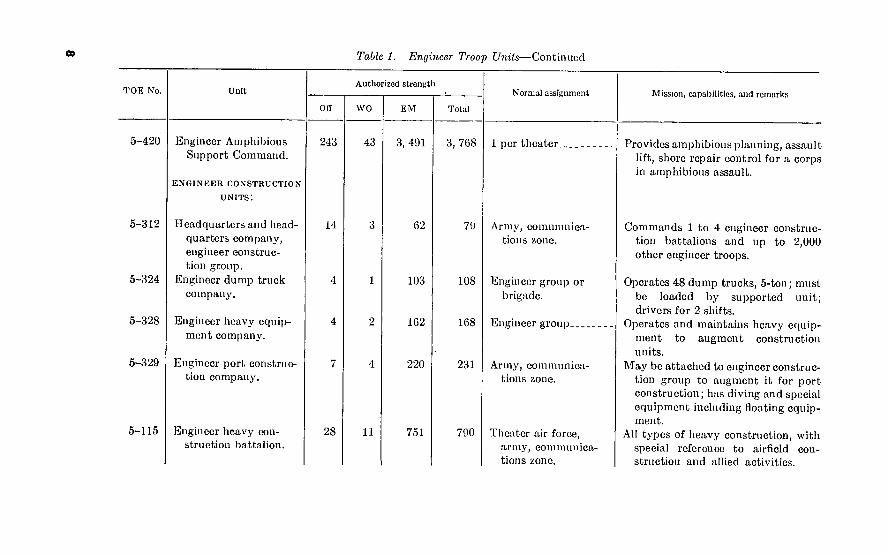
00 Table 1. Engineer Troop Units—Continued
TOE No.
5-420
5-312
5-324
5-328
5-329
Unit
Engineer Amphibious Support Command.
ENGINEER CONSTRUCTION
UNITS:
Headquarters and head- quarters company, engineer construc- tion group.
Engineer dump truck company.
Engineer heavy equip- ment company.
Engineer port construc- tion company.
5-115 Engineer heavy con- struction battalion.
Authorized strength
Oft
243
14
28
wo
43
11
EM
3, 491
G2
103
162
220
751
Total
3, 768
79
108
168
231
790
Normal assignment
1 per theater.
Army, communica- tions zone.
Engineer group or brigade.
Engineer group
Army, communica- tions zone.
Theater air force, army, communica- tions zone.
Mission, capabilities, and remarks
Provides amphibious planning, assault lift, shore repair control for a corps in amphibious assault.
Commands 1 to 4 engineer construc- tion battalions and up to 2,000 other engineer troops.
Operates 48 dump trucks, 5-ton; must be loaded by supported unit; drivers for 2 shifts.
Operates and maintains heavy equip- ment to augment construction units.
May be attached to engineer construc- tion group to augment it for port construction; has diving and special equipment including floating equip- ment.
All types of heavy construction, with special reference to airfield con- struction and allied activities.

5-116
5-117
5-118
5-372
5-376
5-377
5-48
Headquarters company, engineer construction battalion.
Engineer service and support company, engineer construc- tion battalion.
Engineer construction company.
Headquarters and head- quarters detachment, engineer pipeline group.
Headquarters, head- quarters and service company, engineer pipeline battalion.
Engineer pipeline company.
ENGINEER MAINTENANCE
AND SUPPLY UNITS
Engineer supply point company.
116 1 per batatlion
170 1 per battalion
All types of heavy construction, with special reference to airfield construc- tion and allied activities.
All types of heavy construction, with special reference to airfield con- truction and allied activities.
168
64
86
259
3 per battalion
1 per theater head- quarters.
1 per 3 to 5 engineer pipeline companies.
Headquarters, head- - quarters and service
company, engineer pipeline battalion.
All types of heavy construction, with special reference to airfield con- struction and allied activities.
Prepares plans for bulk petroleum handling systems and commands and supervises pipeline construction and maintenance units.
Commands, plans, and supervises the construction, rehabilitation, and field maintenance of petroleum distribution and storage facilities.
Constructs and rehabilitates petroleum unloading and bulk storage facilities and pipeline systems; partial field maintenance of petroleum pipeline systems.
102 Army or independent corps.
Operates engineer supply point in the corps and army areas. May be used to distribute supplies to a large concentration of construction projects or to operate issue section of a large depot.

o Table 1. Engineer Troop Units—Continued
TOE No.
5-157
5-262
5-266
5-267
5-278
5-279
5-387
Unit
Engineer field mainte- nance company.
Headquarters and head- quarters company, engineer maintenance and supply group.
Headquarters and head- quarters detachment, engineer depot battalion.
Engineer depot com- pany.
Engineer depot mainte- nance company.
Engineer parts depot company.
Engineer forestry com- pany.
Authorized strength
Off WO EM Total
15
188
108
38
195
191
172
142
198
131
46
201
199
178
146
Normal assignment
Field army or com- munications zone. Organic to amphib- ious support brigade.
Army communications zone.
Communications zone_-
Communications zonc--
Maintenance and supply groups in communications zone.
Engineer maintenance and supply group.
Communications zone..
Mission, capabilities, and remarks
Provides engineer field maintenance and parts to supported units for organizational maintenance.
Commands group, normally 2 or more battalions of service troops.
Commands 2 to 5 depot and other supply companies.
Operates general engineer supply depot for engineer troops, with labor units attached.
Normally assigned with a parts depot company to support 3 to 4 field maintenance companies.
Provides parts support for 9,000 items of engineer equipment.
Logs timber and operates sawmill; 20 to 40 M. b.m. per day.

5-464
5-55
5-56
5-57
Engineer company, Redstone.
ENGINEER TOPOGRAPHIC
AND INTELLIGENCE
UNITS
Engineer topographic battalion, army.
Headquarters and head- quarters company, en- gineer topographic bat- talion, army.
Engineer map reproduc- tion and distribution company, army.
18
178
10
323
123
106
185
349
139
111
1 per U.S. Army missile command (heavy). Organic to field artillery missile group (heavy).
Army.
Organic to engineer topographic battalion, army.
Organic to engineer topographic battalion, army.
Provides liquid hydrogen and carbon dioxide necessary to support the operations of a REDSTONE mis- sile battalion. Provides field main- tenance for engineer equipment of the missile battalion.
Provides maps and engineer informa- tion as required for an army in the field; prepares and/or reproduces new or existing maps, map substi- tutes, and engineer intelligence data; stores and distributes maps and similar material required by army or corps troops.
Provides command and staff, supply and maintenance, and engineer sur- vey capability for topographic map- ping for the engineer topographic battalion, army. Survey element may carry ground control forward to corps survey elements for artil- lery requirements.
Reproduces, stores, and distributes new and existing maps, photomaps, overlays, and other intelligence material.

Table 1. Engineer Troop Units—Continued
TOE No.
5-59
5-167
5-343
5-344
5-345
5-346
Unit
Engineer photomapping company, army.
Engineer topographic company, corps.
Engineer topographic aviation company.
Engineer base map de- pot company.
Headquarters and head- quarters company, en- gineer topographic sur- vey group.
Headquarters and head- quarters detachment, engineer base topo- graphic battalion.
Authorized strength
OH WO EM Total
Normal assignment
4
89
24
94
107
173
129
127
49
99
114
263
134
155
58
Organic to engineer topographic battalion, army.
1 per corps _
Topographic survey group.
Normally assigned or attached to an engi- neer base topographic battalion.
Zone of interior, thea- ter communications zone.
Communications zone or zone of interior.
Mission, cjijiablUtics, uml remarks
Compiles original, or revises existing, maps and map substitutes; prepares overlays, sketches, drawings, etc. ; for reproduction.
Provides map and survey information in support of corps operations.
Operation and limited maintenance of aircraft supporting large field sur- vey operation.
Normally 1 per communications zone for bulk map storage and distribu- tion.
Commands and supervises attached troops including base topographic battalions.
Provides for the planning and techni- cal control of a flexible base topo- graphic battalion engaged in the compilation, reproduction, and dis- tribution of military maps.

5-347
5-348
5-349
Engineer base reproduc- tion company.
Engineer base survey company.
Engineer base photo- mapping company.
123
165
184
1 each per headquar- ters and headquarters company, engineer base topographic bat- talion.
1 or more per head- ^ quarters and head-
quarters company, engineer base topo- graphic battalion as required, or may operate independ- ently.
1 each per headquar- ters and headquar- ters company, engi- neer base topographic battalion.
Reproduces maps, charts, and allied mapping materials such as map in- dexes, trig lists, and gazetteers as required.
Performs field surveys and computa- tions relative to new mapping or map revision; performs second and third order geodetic surveys; aug- ments field armies’ survey capa- bilities. Performs surveys for mili- tary mapping, artillery, and guided missile needs.
Provides new and revised map manu- scripts for reproduction of multi- colored maps; compiles new maps from aerial photography. Pre- pares controlled mosaics.

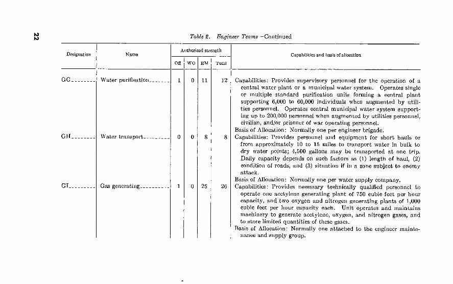
Table 2. Engineer Teams
Designation Name Authorized strength
OB WO EM Total
Capabilities and basis of allocation
AA.
AB.
AC.
AD.
BA.
ADMINISTRATIVE AND
HEADQUARTERS TEAMS
Platoon headquarters, component of com- pany.
Platoon headquarters, separate.
Company headquarters .
Battalion headquarters. 15
SUPPLY TEAMS
General supply 23
22
24
Capabilities: Command and administrative control of 2 or more service teams.
Basis of Allocation: One per two or more service teams with a strength of not less than 40 individuals. Not required if commissioned officers are assigned to the teams.
Capabilities: Command and administrative control of two or more teams not a part of a company.
Basis of Allocation: One per unit comprising 40 to 60 individuals. Not required if commissioned officers arc assigned to teams.
Capabilities: Command and administrative control of two or more service teams.
Basis of Allocation: One per unit comprising 2 or more service platoons with an aggregate strength of not less than 120 individuals.
Capabilities: Command and administrative control of 3 or more service companies, or a group of engineer units of company or smaller size with an aggregate strength of approximately 750 to 1,100 individuals; furnishes direct administrative assistance to separate detachments which arc not attached to companies.
Basis of Allocation: One per group of 3 or more service companies, or teams with an aggregate strength of 750 to 1,100 individuals.
Capabilities: Receives, stores, issues, and maintains records of class II and IV supplies for approximately 35,000 troops.

533500
O O
BB Depot operating
BC Equipment supply.
BD Headquarters, engineer supply control office.
m
Basis of Allocation: Normally augments Engineer Depot Company, TOE 5-267, and may augment TOE 5-500, Depot Operating Team BB; one per special task force up to 35,000 troops.
Capabilities: Operates a depot for the receipt, storage, and issue of engineer general supplies and equipment, and maintains records of class II and IV supplies for approximately 90,000 troops.
Basis of Allocation: Normally augments Engineer Depot Company, TOE 5-267, one per special task force from 70,000 to 90,000 troops.
Capabilities: Operates a small depot for the receipt, assembly, serv- icing, issue, and shipment of engineer mechanical and electrical equipment in support of a small task force or base. Capable of equipment supply for a force which includes approximately 35,000 troops; assembly and initial conditioning of heavy engineer equip- ment for storage or issue to using units; inspection and minor re- pairs on heavy equipment to depot stock to insure serviceability and maintenance of equipment while in storage.
Basis of Allocation: Augments Engineer Depot Company, TOE 5-267, and Engineer Depot Battalion, TOE 5-266, and may aug- ment TOE 5-500, Depot Operating Team BB; one per special task force up to 35,000 troops.
Capabilities: Provides the administrative personnel to staff a Theater Engineer Supply Control Office. When augmented by Teams BE, BF, BG, and BH, the unit comprises a Theater Engineer Supply Control Office capable of: Forecasting general engineer and repair parts supply requirements of a Theater of Operations to insure maintenance of adequate and realistic stock levels; evaluating stock status reports, tonnage reports, and other special supply reports as required or directed; directing the distribution or reloca- tion of supplies; assembling statistical data pertaining to engineer equipment population and distribution; general engineer and repair parts usage experience, identifying and cataloging locally procured items and other pertinent stock control operations.
Basis of Allocation: One per Theater Headquarters.

Table S. Engineer Teams—Continued
Designation Name
BE General engineer supply control team.
BE Engineer repair parts supply control team.
BG Distribution (stock con- trol) team.
Authorized strength Capabilities and basis of allocation
OH WO
1 1
1 1
1 1
EM Total
41 43
41 43
34 36
Capabilities: Provides the necessary supervisors, analysts, and typists to exercise effective supply control over approximately 10,000 to 11.000 general engineer supply items. Maintains a balanced supply of general engineer items throughout the entire Theater of Opera- tions. Forecasts requirements and resupply of general engineer items for future operations to insure the receipt and ultimate distribution of necessary supplies at the proper time and place.
Basis of Allocation: One for control of approximately 10,000 to 11,000 general engineer items.
Capabilities: Provides the necessary supervisors, analysts, and typists to exercise effective supply control over approximately 8,000 to 10.000 rapid turnover repair parts supply line items. Maintains a balanced supply of repair parts items throughout the entire Theater of Operations. Forecasts requirements and resupply of repair parts items for future operations to insure the receipt and ultimate distribution of necessary supplies at the proper time and place.
Basis of Allocation: One for control of approximately 8,000 to 10,000 rapid turnover repair parts supply line items.
Capabilities: Provides the necessary qualified personnel to exercise effective stock control over all general engineer and repair parts items present in or requisitioned for a Theater of Operations. Works in close coordination with the other teams of the Engineer Supply Control Office. Requisitions items from the zone of interior, directs shipments to various storage depots, diverts shipments as necessary, authorizes depot issues, controls ship-

BH Engineer identification and cataloging team.
EA
MAINTENANCE AND PARTS
TEAMS
Field maintenance
EB Field maintenance
mcnts in and ont of depots in accordance with regnlations, controls the disposal of excess and unserviceable items. Based on data furnished by the Theater Army Engineer, with regard to future operations, prescribes depot missions so as to insure effective and proper distribution of available supplies.
Basis of Allocation: One or more as required per Theater Engineer Supply Control Office
Capabilities: Identifies and catalogs repair parts and general engineer items of supply which have been locally procured or which through occurrence or omission have lost their identity. Maintains con- stant liaison with the Theater Procurement Office and local manu- facturers to determine facilities and materials available. Prepares the necessary drawings and blueprints required when requesting bids from local manufacturers. Subsequent to inspection and ac- ceptance of an item, the team in coordination with the Team BG arranges for shipment of the item to a storage installation.
Basis of Allocation: One or more as required per Theater Engineer Supply Control Office.
Capabilities: Provides engineer field maintenance support for approxi- mately 140 major items of engineer construction equipment or 90 vehicle equivalents.
Basis of Allocation: Normally one per special task force requiring a maintenance force of less than a platoon of an engineer field main- tenance company or larger maintenance team.
Capabilities: Provides engineer field maintenance support for approxi- mately 375 major items of engineer construction equipment or 180 vehicle equivalents.
Basis of Allocation: Normally one per special task force requiring a force of less than a platoon of an engineer field maintenance com- pany or to augment an engineer field maintenance company.

00 Table 2. Engineer Teams—Continued
Designation Name Authorized strength
Capabilities and basis of allocation
Off WO
EC. Special equipment main- tenance.
ED. Parts .
EE. Repair parts instructor- adviser.
EM
8
17
4
Total
8 Capabilities: Provides technically qualified personnel to operate a mobile machine shop for the repair of special engineer equipment, including sniperscopes, mine detectors, odographs, searchlights, and small quantities of other infrared devices, precision instruments, and similar items. Team is capable of maintaining approximately 1,050 sniperscopes, 700 mine detectors, 25 odographs, 6 searchlights, and miscellaneous items.
18
5
Basis of Allocation: Normally one per engineer field maintenance company where there is a high concentration of special engineer equipment.
Capabilities: Provides parts supply support for 1,500 major items of engineer equipment employed by an engineer force operating in an area which does not require support of larger parts supply units. Team can issue approximately 3,000 line items per month, and can store approximately 50 tons of repair parts or 9,000 line items.
Basis of Allocation: Normally one per special task force or one per Engineer Field Maintenance Company, TOE 5-157; and as required to support Engineer Parts Depot Company, TOE 5-279, and Engi- neer Depot Maintenance Company, TOE 5-278.
Capabilities: Provides technically qualified personnel for advising, instructing, and rendering assistance to engineer and engineer equipment using units on repair parts problems such as interpre- tation of parts supply policies and procedures, procurement, dis- tribution, supply and stock control, storage, utilization, disposition of excesses, and the recovery of reparable parts.

EF. Engineer field mainte- nance (AAA).
EG Engineer field mainte- nance guided missile (CORPORAL).
FIREFIGHTING TEAMS
FA Firefighting headquarters
Basis of Allocation: To engineer supply control offices and similar organizations and Engineer Maintenance and Supply Group, TOE 5-262, as required.
Capabilities: Provides qualified personnel and equipment to accom- plish field maintenance support of engineer equipment within AAA units.
Basis of Allocation: Normally one per AAA Group outside CONUS composed of two to four AAA Missile Battalions NIKE Semimo- bile TOE 44-145; AAA Battalion 75-mm Gun, Mobile TOE 44-15; AAA Battalion 120-mm Gun, Semimobile TOE 44-115.
Capabilities: Provides immediate field maintenance service for the engineer equipment organic to the Ordnance Guided Missile Direct Support Company (CORPORAL) TOE 9-228, and three Field Artillery Missile Battalions, CORPORAL TOE 6-545. Such sup- port will include repairing and/or replacing engines, assemblies of subassemblies, not above field maintenance level, maintaining bal- anced stocks of repair parts for use of organic maintenance per- sonnel, receive and issue to supported units repair parts for organi- zational use, assemble and report, through engineer maintenance channels, statistical data on supported engineer equipment, inspect- ing organizational maintenance activities, technical inspection of engineer equipment, and furnishing of advice on repair parts stock levels for organizational maintenance, and their storage and usage.
Basis of Allocation: Normally attached to the Ordnance Guided Missile Direct Support Company (CORPORAL) TOE 9-228.
Capabilities: Planning for overall strategic fire defense; controls fire- fighting teams assigned or attached.
Basis of Allocation: Normally one per two to four firefighting teams and one water tank team.

to o Table S. Enijineer Teams—Continued
Designation
FB.
FC.
FD.
GA.
Name
Fire truck.
Fire trailer.
Water tank.
EQUIPMENT OPERATING
TEAMS
Dump truck.
Authorized strength
Off WO EM Total
13 13
Capabilities and basis of allocation
Capabilities: Establishes organized fire protection and fire prevention programs in areas to which assigned; will provide fire protection for areas housing 5,000 to 10,000 troops, or warehouse and open stock pile storage of 100,000 square feet.
Basis of Allocation : One per post, base, camp, or station housing 5.000 to 10,000 troops, or warehouse and open storage area of 100.000 square feet.
Capabilities: This team, including team chief with volunteer personnel, will furnish fire protection to an area housing from 5,000 to 10,000 troops, or warehouse and open storage space of 100,000 square feet.
Basis of Allocation: One per post, base, camp, or station housing up to 5,000 troops, or warehouse and open storage area of 100,000 square feet when a firetruck team is not required.
Capabilities: Transport water for firefighting purposes when insuffi- cient water storage is available.
Basis of allocation: One per firefighting platoon; additional as required.
Capabilities: Provides supervisory personnel, drivers, and dump trucks for hauling bulk materials such as dirt, gravel, coal, road metal, etc. Capacity for hauling depends upon factors such as type of material, distance per trip, and loading facilities. Maxi- mum hauling capacity is 40 tons.

GB Rock crusher
GD Forestry
GE Well drilling
GF Water purification
Basis of Allocation: Normally attached to a dump truck company to augment its hauling capacity; may be attached to construction company or service units when required.
Capabilities: Provides personnel for the operation of the 50 tons per hour crushing and screening plant.
Basis of Allocation: Normally attached to an engineer construction unit to furnish and operate equipment for production of crushed stone necessary for accomplishment of engineer construction mis- sions.
Capabilities: Provides personnel and equipment necessary to conduct logging and sawmill operations for the production of rough lumber and timber piling. Capable of producing 10,000 to 15,000 board feet of rough lumber and timber piling per day.
Basis of Allocation: Normally attached to an engineer forestry com- pany, but may operate independently when the employment of an engineer forestry company is not warranted.
Capabilities: Provides supervisory personnel and equipment for drill- ing water wells; installs casings and pumps for wells to supply water to units or stations.
Basis of Allocation: Normally attached to a construction unit which will provide additional personnel necessary for well drilling opera- tions.
Capabilities: Provides personnel and equipment for purifying up to 3.000 gallons of potable water per hour, and storage facilities for 12.000 gallons.
Basis of Allocation: Normally attached to a water supply company, but may operate independently when the employment of a water supply company is not warranted.
K) N) Table 2. Engineer Teams—Continued
Designation Name Authorized strength
Off WO EM Total
Capabilities and basis of allocation
GG. Water purification. 11
GH. Water transport.
GI. Gas generating. 25
12
26
Capabilities: Provides supervisory personnel for the operation of a central water plant or a municipal water system. Operates single or multiple standard purification units forming a central plant supporting 6,000 to 60,000 individuals when augmented by utili- ties personnel. Operates central municipal water system support- ing up to 200,000 personnel when augmented by utilities personnel, civilian, and/or prisoner of war operating personnel.
Basis of Allocation: Normally one per engineer brigade. Capabilities: Provides personnel and equipment for short hauls or
from approximately 10 to 15 miles to transport water in bulk to dry water points; 4,500 gallons may be transported at one trip. Daily capacity depends on such factors as (1) length of haul, (2) condition of roads, and (3) situation if in a zone subject to enemy attack.
Basis of Allocation: Normally one per water supply company. Capabilities: Provides necessary technically qualified personnel to
operate one acetylene generating plant of 750 cubic feet per hour capacity, and two oxygen and nitrogen generating plants of 1,000 cubic feet per hour capacity each. Unit operates and maintains machinery to generate acetylene, oxygen, and nitrogen gases, and to store limited quantities of these gases.
Basis pf Allocation: Normally one attached to the engineer mainte- nance and supply group.

GJ Carbon dioxide generat- ing.
1 0 12 13
GK. Quarrying and processing 1 (Tentative).
0 36 37
CONSTRUCTION, UTILITIES,
AND ELECTRICAL POWER
TEAMS
HA Port construction head- quarters.
2 0 2 4
HB Diving 1 0 9 10
HC Welding
to <•>
Capabilities: Provides necessary technically qualified personnel for the generating, storage, and transportation of carbon dioxide in gaseous and liquid form and in the form of dry ice. Unit operates machinery for the generation of hydrogen and carbon dioxide gases, and to store limited quantities of these gases.
Basis of Allocation: Normally one attached to the engineer mainte- nance and supply group.
Capabilities: Provides personnel and equipment for the operation of the 225 tons per hour crushing, screening, and washing plant. Provides necessary personnel and equipment for drilling and blasting operations required to produce raw stone for crushing.
Basis of Allocation: To Engineer Heavy Construction Battalion, TOE 5-355, as required. '
Capabilities: Provides technically qualified personnel to augment an engineer staff section or unit for the performance of specialized phases of port planning, such as capacity, layout, site selection, design, material requirements, and special equipment needs.
Basis of Allocation: Normally one per engineer group when engaged in major port projects.
Capabilities: Provides personnel and equipment to perform marine diving in support of port construction and rehabilitation and other types of engineer construction, including underwater pipelines which may require diving personnel and equipment.
Basis of Allocation: Normally one per engineer group when engaged in major port or underwater pipeline projects.
Capabilities: Provides technically qualified welders and equipment for attachment to units where the organic personnel and equipment are inadequate.
Basis of Allocation: Normally one per engineer construction group and two per engineer maintenance and supply group.

to ■«k Table 2. Engineer Teams—-Continued
Designation
HD Utilities
Name
HE. Utilities
HF. Utilities
HG. Utilities
Authorized strength Capabilities and basis of allocation
Off WO EM Total
1 0 27
1 44
52
79
28
46
55
83
Capabilities: Provides personnel and equipment for maintenance of utilities at installations up to 2,500 individuals; provides post engi- neer service to overseas or theater of operations installations; maintains utilities and furnishes utilities service and repair, including refrigeration maintenance.
Basis of Allocation: Normally one per overseas camp, base, depot, or installations up to 2,500 individuals.
Capabilities: Provides personnel and equipment for maintenance of utilities at installations up to 4,000 individuals; provides post engineer service in overseas or theater of operations installations; maintains utilities and furnishes utilities service and repair, including refrigeration maintenance.
Basis of Allocation: Normally one per overseas camp, base, depot, or installations up to 4,000 individuals.
Capabilities: Provides personnel and equipment for maintenance of utilities at camps, bases, and depots for installations up to 6,000 individuals; provides post engineer service in overseas or theater of operations installations; maintains utilities and furnishes utilities service and repair, including refrigeration maintenance.
Basis of Allocation: Normally three in communications zone area per supported field army.
Capabilities: Provides personnel and equipment for maintenance of utilities at camps, bases, and depots for installations up to 10,000 individuals; provides post engineer service in overseas or theater of operations installations; maintains utilities and furnishes utilities service and repair, including refrigeration maintenance.

HH Power line
HI. Powerplant maintenance-
HJ. Powerplant operating
HK Foundry
in
Basis of Allocation: Normally one per typical field army and two in communications zone area per supported field army.
Capabilities: Provides technically qualified personnel and tools for the installation of high voltage electric power lines, and the maintenance of approximately 60 miles of high voltage electric power lines.
Basis of Allocation: Normally one per two electric power generating plants of 300 to 2,500 kw. capacity.
Capabilities: Provides technically qualified personnel and equipment for maintenance 'pf electric power generating plants of 300 to 2,500 kw. capacity, when welding team HC is attached, and furnishes supervisory personnel for construction and rehabilitation of such plants.
Basis of Allocation: Normally one per two electric power generating plants of 300 to 2,500 kw. capacity.
Capabilities: Provides technically qualified personnel for the opera- tion of electrical powerplants containing from one to three diesel engine driven generators, capacities of which range from 300 to 2,500 kw.
Basis of Allocation: Normally four per engineer brigade in com- munications zone area.
Capabilities: Provides technically qualified personnel for the oper- ation of one set of engineer foundry equipment.
Basis of Allocation: Normally one per engineer depot maintenance company when foundry service is required.

Tabic 2.
O Designation Name
HL Engineer floating power- plant.
HL.
HM
Engineer floating power- plant.
Railway mounted power- plant.
Authorized strength
Off WO EM
60
Total
66
60
14
66
16
'■r Teams—Continued
Capabilities and basis of allocation
Capabilities: When augmented by one mess team CA and two mess teams CB from TOE 29-500, this unit is capable of 24-hour opera- tion for extended periods at full rated load; providing continuous 3-phase, 60-cycle, electric power in quantities up to 34,500 kw. at output voltages between 13,800 and 115,000 volts; supplying electric power to civilian or military installations near shore, harbor, or navigable stream at proper voltages by means of variable step-up transformers; supplying electric power to shore and inland areas by means of connection to existing transmission lines. Capable of routine and emergency maintenance and minor repairs of equip- ment by assigned personnel. Towing vessel is required to move this ship.
Basis of Allocation: As required in theater of operations, communica- tions zone, and zone of interior.
Capabilities: Provides electric power for direct support of our Armed Forces and to meet any critical electrical requirements of civilians in occupied countries; to provide sufficient electrical power for military installations, industrial plants, or limited population centers at proper voltages through variable step-up transformers; to meet varying foreign and domestic situations of either 50- or 60-cycle current under a wide variety of output voltages; supply electrical power to areas by means of connection to existing transmission lines; capable of 24-hour operation for extended periods at full rated load with powerplant operations to be carried on by assigned personnel; capable of routine and emergency maintenance and minor repairs of equipment by assigned personnel. Unit is not self-propelled and a towing engine must be furnished.
Basis of Allocation: As required in theater of operations and zone of interior.

HN Engineer Camouflage (Heavy Weapons).
1 0 36 37
TOPOGRAPHIC AND
INTELLIGENCE TEAMS
IA Survey. 0 0 14 14
IB Survey platoon 1 0 39 40
IC Photomapping platoon 1 1 77 79
ID Map reproduction pla- 1 toon.
1 51 53
to N
Capabilities: Provides personnel and equipment for the employment of the Decoy Target Gun 280-mm. w/Carriage Medium Fidelity Pneu w/Carrying Case in a theater of operation.
Basis of Allocation: Normally one per 280 mm. Gun, Field Artillery Battalion in the theater of operations. As required when other deception operations are contemplated.
Capabilities: Provides technically qualified personnel and equipment for the survey operations of one party.
Basis of Allocation: Normally one per engineer brigade. Capabilities: Provides technically qualified personnel and equipment
for three survey parties, and limited preparation of map manu- script.
Basis of Allocation: Normally attached to Engineer Base Survey Company, TOE 5-348, when mapping operations require addi- tional effort but less than a base survey company.
Capabilities: Provides technically qualified personnel and equipment for the preparation of topographic maps by multiplex methods from aerial photographs.
Basis of Allocation: Normally attached to Engineer Base Photo- mapping Company, TOE 5-349, when mapping operations require additional effort but less than a base photomapping company.
Capabilities: Provides technically qualified personnel and equipment for the production of maps from original manuscrips, and limited quantities of photostats.
Basis of Allocation: Normally attached to Engineer Base Map Repro- duction Company, TOE 5-347, when mapping operations require additional effort but less than a base map reproduction company.

Table
2
. E
ngin
eer T
eam
s—
Conti
nued
o >
«a o
'S g 0) ïï £ J
Qi V2
'S a
- S o lu c o
§ S en O
o ’•+3
J£ ce w
^ 15
c3 S
-Í5 W) «
en s-, D o 'O -+-= • -< (Zî
2 ^2 63 a Û> c3
+3 *H c3 Ù) tH O O Q,
S* o O -JJ
fi >î c3 fi ü E en fi
5 t-1
I a * Qi
PH £
Æ ■+^
CO K. f-, >i a> e:
■e * fi g s i— CT O
’S ^ o .. I
_c o
1 “I 115
fi ^ fi C o _ ü g c
T3 ° -2 S ^ o « , T3
g I § I en tH en Qi -
^ fi Tl « O M
ce
uj Qi O
&
fi co 5, 03 ^ T3
t* •2 .S *e ‘S
a* ° « 03 9,
en
CL •fi' tn fi ^ CL ^ f!î O C3 . ^
o c
^ 03
S I I •o .S o •r «o > .— CL O ^
-4-3 fi O fi
If 03 hT
fi tH CH O fi ^
O
>» o £ « fi W 03 fi
ffl
<n ' - .S -Í3 o
CO o — CO
s 8 o' fi Ä lO c. o *: fi ^ ^
fi tH
O g bß .g .« bD
£ •2“ ’^3 e -t5
c « 03 2 fi
64) 3 e o
a e br Kft W) fi e tn
,c rv — d £
"O o "S ^ o fi -- O
e c 03
TJ C fi
tH .£ O bû CL £ 03 03
CL
T3 fi
JD ce
g fi ft 3
^ cr 03 C >> O =3
>, O
^ s
ü -g ft 5 fi co tH ^ bD 03 O 03
-4-3 r“ O <D j£ bD ft e:
^ o ” £ co C
.2 'fi 03 t? ^ fi • ^ -H-3 N co '“Ce 5 .2 -
-5 £ O S o
ce -4-3
TJ 2 £ ^ «5 T
b£ §
.£ 03
le «. CL 03 fi g
feb 03 O bD
-t» ie
ss » c
C J2 -£ — 03 03
O Q £ ft 03 bû £ ■ = 63 :
03 S • - > -4-3 -43 £ .C 03
tH fi 03 fi CL CT 03
3. fi S £ B 03 tn 03 o ■*> ^ co ^ 03 .. 73
O £
.*a fi -4-3 03 G •£ 03 fi s a
03 bD '+3
£ >-
3 73 fi G ^
5S
c ^
.£ S fi £
-4-3 tn O
ñ
.£- c
c -s 'S c fi 03 <G £
O
.2 fi CO ft , fi fi '
PQ O
- -*J CO 03 bD G fi
.S' ‘C £ fi
¿2 ft « 03
tn W fi
£ >>£ fi -fi G
S s f tH E « 03 O ^ 2 co
'5b •• 3 g g ^
g-'S fi £ 03 03 O • • Í5 .-H co £ >-n 03
bD «H-H —
.£ 0 s O -S2 S cg w ft ^ fi fi
PP O
bD „ £ fi -5 .2 fi G G J£
g g
_ tH
bû 2
.£ c
.> "Sb -° o c 03 03 03 tH «4-H
O bD _ aco ■4-3
S3 c 03 03
¡2 S o _ 03 Q3
« 2 .2 2 HJ CL 2 o S o
I'2 g o3
JS ^ o
g S
8 ^
S I
bD G £ 03 fi
■ S £ ►, .s a •«03-0
03
5 'a o
co
-g ü
1 - .£ ’3 ■HO», o
g O 2
HJ CO fi g N tn
G TJ fi £ bD fi tn
G en „ £
P O O S3
O G <4-H
jn O
'3 g
bû ’-3 £ fi
•fi bD .£ O
— U, <0
§ s fe
. g a 03 +3 03 g 03 g g 03 O bD fi >>
O « G
O
ft G fi ts ft 03 ‘n —
O G «4-1 O
I - fi co
a .a
bD .£
•S ® â- CL O j£ *S •+*
“'’g TJ £ ^ 3 «
bpl
•S <
- ft O g ^
2 fi •• ■2 .2 G bD c ° G Æ '-5 03 çj fi
03 03 ë G
*■ - tH TJ 03 •< 03
^ £ ft £ .« O G bp co O O -s m a> g
PQ
S w
00 CC
— ft O CL
bD
.£ 2 fi £
&
£ fi £
•2 S c ‘S3 ft 2
PÍ
H PH O «
28

IJ Geodetic survey. 4 1 7 12
IK. Terrain 11
IL Topographic liaison 7 1 9 17
IM Photographic evaluation 0 1 8 9
to >o
Capabilities: Provides technically qualified personnel for instruction and/or supervision of units engiiged in high-ordcr geodetic surveys and computations as required in a theater of operations survey program and as otherwise required in the field army for guided missile support.
Basis of Allocation: One per theater of operations and normally one per field army when required.
Capabilities: Provides technically qualified personnel and equipment for the collection, evaluation, and dissemination of terrain data; the production of terrain studies; and provision of consultant services in military geology and military hydrology.
Basis of Allocation: Normally one pur army but may be assigned at a lower level.
Capabilities: a. Map program planning and technical supervision of map com-
pilation; surveying and geodetic activities including supervision, collection, maintenance and dissemination of survey control data; supervision and coordination of map reproduction including evaluation of reproduction facilities and planning the employment of such facili- ties in the map reproduction program; supervision of the topographic and map supply program; including operation of map depots and supply points throughout the command. Maintains liaison with higher headquarters and allied armies. Supervise non-United States indigenous reproduction and mapping agencies used in the program.
b. Transportation will be provided by area motor pools, or organ- ization to which attached. Basis of Allocation: One per theater, army group, field army head-
quarters, or base topographic battalion as required. Capabilities: Provides technically qualified personnel and equipment
for assisting photographic units in accomplishing aerial cartographic photography suitable for the compilation of military topographic maps, also the evaluation of such photography to determine its suitability for the required purpose.

U o Table Engineer Teams—Continued
Designation
JA-
JB.
JC.
Name
DREDGE CREWS
20-inch-cutter pipeline dredge.
24-ineh-cutter pipeline dredge.
Authorized strength
Off WO EM Total
700-cubic-yard diescl- clcctric seagoing hopper dredge.
48
38
39
58
47
48
Capabilities and basis of allocation
Basis of Allocation: As required, normally attached to Headquarters and Headquarters Detachment, Engineer Base Topographic Bat- talion, TOE 5-346.
Capabilities: When augmented by labor personnel from TOE 10-67 or other available labor sources and a minimum of one mess team CA and one mess team CB from TOE 29-500, this unit provides per- sonnel for the operation and maintenance of the engineer dredge, non-self-propelled, diesel powered, 20-inch-cutterhead type, pipe- line.
Basis of Allocation: As required. Capabilities: When augmented by labor personnel from TOE 10-67
or other available labor sources, and a minimum of one mess team CA and one mess team CB from TOE 29-500, this unit provides per- sonnel for the operation and maintenance of the engineer dredge, turbine powered, 24-inch-cuttcrhead type, non-self-propcllcd, pipeline.
Basis of Allocation: As required. Capabilities: When augmented by a minimum of one mess team CA
and one mess team CB from TOE 29-500, this unit provides per- sonnel for the operation and maintenance of the engineer dredge, seagoing hopper, diesel electric powered, 700 cubic yard.
Basis of Allocation: As required.
533506
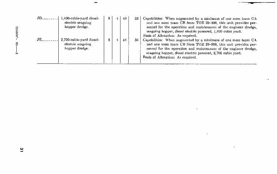
JD 1,400-cubic-yarcl diesel electric seagoing hopper dredge.
O O
w
JE. 2,700-cubic-yard diesel electric seagoing hopper dredge.
<o
Capabilities: When augmented by a minimum of one mess team CA and one mess team CB from TOE 29-500, this unit provides per- sonnel for the operation and maintenance of the engineer dredge, seagoing hopper, diesel electric powered, 1,400 cubic yard.
Basis of Allocation: As required. Capabilities: When augmented by a minimum of one mess team CA
and one mess team CB from TOE 29-500, this unit provides per- sonnel for the operation and maintenance of the engineer dredge, seagoing hopper, diesel electric powered, 2,700 cubic yard.
Basis of Allocation: As required.
1
CHAPTER 3
LOGISTICAL DATA
Section I. EQUIPMENT OTHER THAN MOTORIZED
6. Engineer Equipment Table 3 gives the nomenclature, dimensions, cubages, and weights of
sets of engineer equipment and engineer equipment chests.
32

Table S. Sels of Engineer Equipment
u u
SM 5-4
1080-S01 1080-S02 1080-S03 1080-S04 1080-S05 1080-S06
1080-S07 1080-S08 1080-S09
1080-810---
1080-811.-.
1080-812...
1080-813--.
1080-814-..
1080-815..- 1080-816.-- 1080-817...
1080-818--- 1080-819...
Nomenclature
CAMOUFLAGE TRAINING SET: Aviation Engineer. CAMOUFLAGE TRAINING SET: Company CAMOUFLAGE TRAINING SET: General Purpose CAMOUFLAGE TRAINING SET: Maintenance CAMOUFLAGE NET SET : Single Engine Aircraft CAMOUFLAGE NET SET: Antiaircraft Machincgun, 50
Caliber. REP AIR EQUIPMENT: Pneumatic Target, Set No. 8 CAMOUFLAGE NET SET: Field Artillery, Drape Type CAMOUFLAGE NET SET: Field Artillery, Drape Type,
75-mm. Gun, 105- and 155-mm. Howitzers and Ser 784. CAMOUFLAGE NET SET: Antiaircraft Gun, Drape
Type, 40-mm. Gun. CAMOUFLAGE NET SET: Antiaircraft Machine
Drape Type, 50-Caliber Gun. CAMOUFLAGE NET SET: Antiaircraft Gun, M2,
105- and 155-mm. Gun. CAMOUFLAGE NET SET: Antiaircraft Gun, M2,
40-mm. Gun. CAMOUFLAGE NET SET: Antiaircraft Gun M2,
90-mm. Gun. CAMOUFLAGE NET SET: Field Artillery CAMOUFLAGE NET SET: Twin Engine Fighter Aircraft.. CAMOUFLAGE NET SET: Antiaircraft Gun, U/VV
120-mm. Gun. COVER, SHADE: Bomber Aircraft COVER, SHADE: Fighter Aircraft
Gun,
U/W
U/W
U/W
Length On.)
Width (in.)
Height (in.)
Cu. Ft.
879. 0 326. 9 284. 6 102. 0 80. 0
6. 0
6. 6 179. 0
65. 0
362. 0
32. 5
44. 0
17. 0
17. 0
43. 5 95. 0 38. 2
200. 0 50. 0
Weight (lb.)
15, 150. 0 7, 150. 0 3, 000. 0 1, 597. 0 1, 271. 0
145. 0
180. 0 1, 904. 0
997. 0
573. 0
527. 0
930. O
412. 0
412. 0
968. 0 2, 000. 0 1, 411. 0
4, 800. 0 1, 150. 0

U -h
Table S. Sels of Engineer Equipment—Continued
SM 5-4 Nomenclature
1095-S01 MINE PLANTING EQUIPMENT: Mechanical 2090-S02 CONSTRUCTION OUTFIT: Raft, Infantry Support 2090-S04 REPAIR EQUIPMENT: Plywood Boat and Ponton 2090-S05 REPAIR KIT: Inflatable Craft 2909-S06 REPAIR KIT: Aluminum Craft 2090-S07 REPAIR EQUIPMENT: Plastic Assault Boat 3220-S01 SHOP EQUIPMENT, WOODWORKING, Base Main-
tenance. 3220-S02 SHOP EQUIPMENT, WOODWORKING, Base Main-
tenance, Trailer Mounted. 3424-S01 SHOP EQUIPMENT: Forge, Base Maintenance 3428-S01 SHOP EQUIPMENT: Base Maintenance, Foundry 34:49-801 SHEET METALWORKING SET: Machine, Set 2 3470-S02 SHOP EQUIPMENT: Machine, Shop, Base Maintenance 3540-S01 PRESERVATION AND PACKAGING EQUIPMENT
SET: Unmounted. 3540-S01 PRESERVATION AND PACKAGING EQUIPMENT
SET: Mounted on 6-ton Semitrailer. 3610-S01 REPRODUCTION SET: Ammonia Process 3610-S02 REPRODUCTION SET: Black and White Process 3610-S05 REPRODUCTION SET: Spirit Process, 22/2 by 29 in 3610-S06 REPRODUCTION SET: Ammonia Process, Continuous
Tone. 3610-S07 REPRODUCTION SET: Topographic, Photolithographic,. 3610-S13 REPRODUCTION SET: Silk Screen Process
Length (in.)
Width (in.)
Height (in.)
Cu. Ft.
6, 125. 0 813. 0
6. 1 77. 0 14. 6
2. 0 250. 0
699. 0
1, 967. 0 3, 650. 0
350. 0 3, 590. 0
576. 0
2, 395. 0
75. 0 10. 0 93. 9
220. 0
2, 130. 0 19. 0
Weight (lb.)
61, 200. 0 9, 912. 0
218. 0 1, 200. 0
23. 6 110. 0
4, 800. 0
6, 100. 0
36, 215. 0 108, 400. 0
74, 000. 0 75, 000. 0 17, 500. 0
28, 000. 0
790. 0 230. 0 800. 0
3, 800. 0
23, 233. 0 619. 0

3610-S14
co Ul
3610-S16
3610-S17
3610-S18
3610-S19.
3610-S20
3610-S22
3655-S03
3695-SOl 3820-S01.
3820-S02
3820-S03. 3820-S04.
3820-S05.
3820-S06. 3820-S07. 3820-S08. 3820-S09.
PHOTOGRAPHIC PRINTING AND PROCESSING SECTION: Topographic Reproduction Set, 190-in. Wheelbase.
PLATE GRAINER SECTION, TOPOGRAPHIC RE- PRODUCTION SET: Truck Mounted.
PRESS SECTION, TOPOGRAPHIC REPRODUCTION SET: Truck Mounted.
LABORATORY SECTION: Topographic Reproduction Set, Truck Mounted.
MAP LAYOUT SECTIONS: Topographic Reproduction Set, Truck Mounted.
PLATE PROCESS SECTION: Topographic Reproduction Set, Truck Mounted.
CAMERA SECTION: Topographic Reproduction Set, Truck Mounted.
324. 0
107. 0
324. 0
324. 0
324. 0
324. 0
333. 0
96. 5
72. 0
96. 5
96. 5
96. 5
96. 5
96. 0
132. 0
77. 0
132. 0
132. 0
132. 0
132. 0
132. 0
2, 388. 4
344. 0
2, 388. 4
2, 388. 4
2, 388. 4
2, 388. 4
2, 442. 0
GENERATING AND CHARGING PLANT: Hydrogen Carbon Dioxide, Semitrailer Mounted.
LOGGING EQUIPMENT SET: Truck Mounted PNEUMATIC TOOL AND COMPRESSOR OUTFIT:
Trailer Mounted, 55 c.f.m. PNEUMATIC TOOL AND COMPRESSOR OUTFIT:
Truck Mounted, 210 c.f.m. EXPLORATORY CORE SET: Airborne PAVING BREAKER SET, PORTABLE: For Breaking
Concrete. CRUSHING, SCREENING AND WASHING PLANT:
150 tons per hr. DRILL SHARPENING EQUIPMENT ROCK DRILLING EQUIPMENT: 50 tons per hr AUGERING SET: Earth, Airborne CRUSHING, SCREENING AND WASHING PLANT:
Diesel and Electric Driven, 225 tons per hr.
17, 400. 0
2, 761. 8 82. 0
1, 227. 0
75. 0 17. 9
9, 167. 0
540. 0 575. 0
60. 0 35, 000. 0
21, 030. 0
11, 790. 0
23, 200. 0
18, 550. 0
18, 090. 0
18, 950. 0
17, 520. 0
732, 800. 0
26, 645. 0 1, 800. 0
17, 300. 0
550. 0 550. 0
100, 000. 0
13, 300. 0 15, 600. 0
400. 0 415, 000. 0

(lb.)
000. o
500. 0 266. 0 240. 0
000. 0 200. 0 398. 0 340. 0 123. 0
80. 0
232. 0
700. 0
29. 0
, 700. 0
, 000. o
, 000. o
Table 3. Seis of Enijineer Eqid'pmcnl—Continued
Nomenclature Lenpth (in.)
Width (In.)
Height (In.)
CRUSHING, SCREENING AND WASHING PLANT: Gasoline and Electric Driven, 225 tons per hr.
MAGNET, SWEEPER, ROAD PIPELINE EQUIPMENT SET: For 2^-ton truck PIPELINE CONSTRUCTION EQUIPMENT: Truck
Mounted. ASPHALT, MIXING AND PAVING SET: 80 tons per hr.. JETTING SET: Portable FIRE FIGHTING EQUIPMENT SET FIRE FIGHTING EQUIPMENT SET FIRE FIGHTING EQUIPMENT SET: Set 3 Pumper 400
g.p.m., W/Trailcr, Overseas. REPAIR AND REFILLING KIT: Carbon Dioxide Fire
Extinguisher. FIRE FIGHTING EQUIPMENT SET: Truck Mounted,
Zone of Interior. FIRE FIGHTING EQUIPMENT SET: Set 18, W/Truck,
Overseas. FIRE FIGHTING EQUIPMENT SET: W/Truck, Guided
Missile. FIRE FIGHTING EQUIPMENT SET: W/Trailcr, Guided
Missile. FIRE FIGHTING EQUIPMENT SET: W/Truck and
Trailer Redstone Missile. FIRE FIGHTING EQUIPMENT SET: Set 21, W/Truck,
Army Aircraft Crash.

340. 0
, 219. 0 711. O 130. 0
882. 0
515. 0
136. 0 158. 0
610. 0
62. 0
775. 0
900. 0
720. 0 100. 0
650. 0
602. 0
422. 0 700. 0
FORCED ENTRY AND RESCUE EQUIPMENT SET: Aircraft Crash.
DIVING EQUIPMENT SET: 2 Persons, 200-foot Depth DIVING EQUIPMENT SET: 2 Persons, 100-foot Depth._ DIVING EQUIPMENT SET: Laru, 1 Person, 30-foot
Depth. PUMP ASSEMBLY: Rotary, Power Driven, ENG Well
Development and Production Set 1. PUMP ASSEMBLY: Rotary, Power Driven, ENG Well
Development and Production Set 2. WATER PLANT: EQUIPMENT SET: 900 gal. per hr.... WATER PURIFICATION EQUIPMENT SET: 2,100
gal. per hr. WATER PURIFICATION EQUIPMENT SET: Diato-
mite Filter, 3,000 gal. per hr. Set 4. FILTER UNIT: Water Purification, Knapsack Type, }4
g.p.m. Hand Driven. DISTILLATION EQUIPMENT SET: Water, Trailer
Mounted, 60 gal. per hr. DISTILLATION EQUIPMENT SET: Water, Skid
Mounted, 150 gal. per hr. SHOP EQUIPMENT: Base Maintenance, Electrical Repair. SUPPLEMENTARY EQUIPMENT: Heavy Shop Com-
pany. SUPPLEMENTARY EQUIPMENT: Maintenance Com-
pany. GENERAL PURPOSE REPAIR SHOP EQUIPMENT:
Base Maintenance. TOOLROOM EQUIPMENT: Heavy, Base Maintenance SHOP EQUIPMENT: General Purpose Repair, Semi-
trailer Mounted.

co 00
Table 3. Sels of Engineer ©yttipmeMi—Continued
SM 5-4 Nomenclature Length (in.)
Width On.)
Height (in.)
Cu. Ft. Weight (lb.)
4940-S12 ,
4940-S13
4940-S14
SHOP EQUIPMENT: Organizational Repair, Light, Truck Mounted.
SHOP EQUIPMENT : Contact Maintenance, Truck Mounted.
SHOP EQUIPMENT: Electrical Repair, Semitrailer Mounted.
2, 230. 0
906. 0
2, 296. 8
22, 120. 0
8, 980. 0
20, 600. 0
5180-S01. 5180-S02. 5180-S03. 5180-S04. 5180-S05. 5180-S06.
5180-S08 5180-S09
5180-811. 5180-S13. 5180-S15 5180-S16 5180-S17 5180-S18 5180-S19 5180-S20 5180-S22 5180-S23 5180-S24
ERECTION OUTFIT: High Bolted Storage Tanks TOOL KIT: Supplemental, Pipeline Pump Station ERECTION OUTFIT: Low Bolted Storage Tanks TOOL KIT: Carpenter’s Engineer Squad TOOL KIT: Carpenter’s Engineer Platoon TOOL KIT: Carpenter’s Set 3, Engineer Combat Platoon,
w/case. TOOL KIT: Sheet Metal Worker’s TOOL AND EQUIPMENT KIT: Pioneer, M-4 Floating
Bridge, Set 5. INTRENCHING OUTFIT: Infantry PNEUMATIC TOOL OUTFIT: Set 1 TOOL KIT: Pioneer, Engineer Combat Platoon TOOL KIT: Pioneer, Engineer Platoon, Set 2 TOOL KIT: Pioneer, Engineer Squad TOOL KIT: Pioneer, General Utility TOOL KIT : Mason and Concrete Finisher’s TOOL KIT: Tractor, Base Maintenance, Set 8 TOOL KIT: Blacksmith’s, General TOOL KIT: Diesel Injector Repair, Set 9 TOOL KIT : Rigging, Wire Rope
96. 0 2. 0 1. 5
17. 0 8. 0 5. 0
2, 700. 0 80. 0 70. 0
330. 0 230. 0 132. 0
7. 0 176. 0 34. 0 1, 245. 0
250. 0 128. 3
12. 0 221. 0
26. 0 N/A 7. 6 4. 7
29. 0 2. 6 3. 5
4, 650. 0 3, 040. 0
325. 0 2, 075. 0
752. 0 N/A
103. 0 351. 0
1, 160. 0 62. 0
167. 0

b) ■o
5180-S25 5180-S26 5180-S27 5180-S28 5180-S30
5180-S31 5180-S32 5180-S33 5180-S34 5180-S36 5180-S38 5180-S39 5420-S02 5420-S04 5420-S05 5420-S06 5420-S07 5420-S08 5420-S09
5420-S10 5420-S11
5420-S12 5420-S13 5420-S14
5420-S15 5420-S16
TOOL KIT: Pioneer Cavalry TOOL KIT: Light Machine Repair TOOL KIT: Precision Instrument Repairs TOOL KIT: Service Refrigerator Unit, Set 7 TOOL/EQUIPMENT KIT: Supplementary, Water Supply
Company. TOOL KIT: Outboard Motor Repair, Set 5 TOOL KIT: Tractor, Field Maintenance, Set 7 TOOL KIT: Pipe Fitter’s, Set 1 TOOL KIT: Pipefitter’s, Set 2 TOOL OUTFIT: Pioneer, Portable Electric Tools TOOL KIT: Pipeline Construction, Grooved Coupling TOOL KIT: Pipeline Cutting, Grooving and Beveling BRIDGE ERECTION SET: Fixed Bridge, Steel, Railway,. BRIDGE: Floating, Aluminum, Highway Type, M-4 BRIDGE: Floating, Highway, Class 60 BRIDGE1 Floating, Steel Treadway Widened CABLEWAY SET: Aerial, 3,000 lb. FERRY CONVERSION SET: Raft BRIDGE ERECTION SET: Suspension Bridge, for Foot-
bridge and Light Equipment Bridge. BRIDGE SUSPENSION: Foot 2,000 lb. capacity BRIDGE SUSPENSION: Light Equipment, 4,000 lb.
capacity. TRAMWAY SET: Aerial, Light M-2 TRAMWAY EXTENSION SET: Aerial, 1,000feet CASUALTY EVACUATION SET: Cable, Gravity, 200 lb.
capacity. BRIDGE ERECTION SET: Floating Bridge BRIDGE, FIXED: Steel, Highway, 30 ft. Ig. of Span,
Semipermanent.
6. 0 6. 3
11. 0 7. 8
57. 0
175.0 200. 0 308. 0 317. 0 780. 0
1. 4 3. 5 7. 0 9. 0
248. 0 28. 0
160. 0 650. 0
49, 880. 0 41, 000. 0 11, 320. 0
1, 200. 0 26. 0 N/A
44. 0 216. 0 200. 0
45. 0 1, 950. 0
900. 0 4, 500. 0
18, 400. 0 576, 000. 0 834, 000. 0 299, 000. 0
20, 000. 0 468. 0
N/A
130. 0 62. 0
5, 260. 0 3, 850. 0
, 369. 0 588. 0
16. 0
51, 290. 0 10, 000. 0
710. 0
175. 0 302. 0
4, 775. 0 12, 920. 0

■U o Table 3. Sels of Engineer Equipment—Continued
SM 5-4
5420-S17-
5420-S18-
5420-S20- 5420-S21.
5420-S22 _ 5420-S23- 5420-S24. 5420-S25- 5420-S26- 5420-S27-
5420-S28-
5420-S29-
5420-S30_ 5420-831-
5420-832-
5420-833. 5420-834. 5420-835.
Nomcnclaturo Length (in.)
Width (in.)
Height (in.)
BRIDGE, FIXED: Steel, Highway, GO ft. Ig. of Span, Semipermanent.
BRIDGE, FIXED: Highway, 90 ft. Ig. of Span, Semi- permanent.
BRIDGE, FIXED: Steel, Railway, 17 ft. Ig. of Span BRIDGE, FIXED: Steel, Railway Type, 21 ft. Ig. of Span
I-Bcam. BRIDGE, FIXED: Railway, 27ft. Ig. of Span BRIDGE, FIXED: Railway, 31 ft. Ig. of Span BRIDGE, FIXED: Railway, 35 ft. Ig. of Span GIRDER SPLICING SET: Fixed Bridge, I-Beam, 25 in GIRDER SPLICING SET: Fixed Bridge, I-Beam, 19 in BRIDGE, FIXED: Railway Type, 123 ft. Ig. of Span,
Through Truss. BRIDGE CONVERSION SET: Fixed Bridge, Steel, Rail-
way, Set A. BRIDGE CONVERSION SET: Fixed Bridge, Through
Truss BRIDGE CONVERSION SET: Fixed Bridge BRIDGE CONVERSION SET: Fixed Bridge, Through
Truss. BRIDGE CONVERSION SET: Fixed Bridge, Through
Truss. BRIDGE, FIXED : Railway, 70 ft. Ig BRIDGE, FIXED: 70 ft. Ig. of Span, Through BRIDGE CONVERSION SET: Fixed Bridge, Unit Con-
struction.
Cu. Ft. Weight (lb.)
892. 0
1, 944. 0
60. 6 160. 0
205. 2 339. 8 382. 2
1. 6 1. 5
5, 240. 0
20. 0
53. 6
5. 5 8. 0
1, 271. 0
1, 797. 0 1, 320. 6
24. 8
45, 800. 0
61, 600. 0
5, 104. 0 8, 655. 0
11, 518. 0 18, 568. 0 20, 835. 0
202. 0 150. 0
273, 324. 0
3, 360. 0
3, 549. 0
353. 0 531. 0
69, 679. 0
145, 338. 0 97, 361. 0
3, 773. 0

■U
5420-S36
5420-S37
5420-S38
5420-S39 5420-S43
5420-S44.
5420-S45.
5420-S46.
5420-S47. 5420-S48. 5420-S49.
5420-S51. 5420-S52. 5420-S53.
5420-S54-
5420-S55. 5420-S56-
5420-S57.
BRIDGE CONVERSION SET: Fixed Bridge, Uuit Con- struction.
BRIDGE CONVERSION SET: Fixed Bridge, Unit Con- struction.
BRIDGE CONVERSION SET: Fixed Bridge, Unit Con- struction.
BRIDGE, FLOATING: Aluminum, Foot BRIDGE CONVERSION SET: Fixed Bridge, Bailey Panel
Crib Pier. BRIDGE ERECTION SET, FLOATING BRIDGE: Class
60 with Steel Superstructure. REPAIR EQUIPMENT: Aluminum Floating Bridge, for
M4 Bridge, Floating. TRAMWAY SET: Aerial, Light, Pioneer Tramway and
Cableway. TRESTLE, RAILWAY: Steel, L-Type TRESTLE, RAILWAY: T-Type BRIDGE, FLOATING: Aluminum, Highway, Deck Balk
Superstructure. BRIDGE, FIXED: Steel Highway Type TRAINING SET: Floating Bridge BRIDGE, FIXED: Aluminum, Single Lane, Highway,
Pony Truss. BRIDGE, ERECTION SET: Fixed Bridge Aluminum,
Single Lane, Highway, Pony Truss. BRIDGE, FIXED: Highway, Pony Truss, Bailey Type BRIDGE ERECTION SET: Highway, Pony Truss, Bailey
Type. BRIDGE, FIXED: Aluminum, Highway Type, 38 ft. Ig. of
Span.
122. 0 60. 0 38. 0
63. 6
8. 0
108. 0
1,319. 0 161. 0
185. 0
103. 0
595. 0
. N/A N/A
249. 1
6, 251. 0 53, 000. 0 15, 800. 0
2, 110. 0
1 7, 000. 0
1, 050. 0
10, 294. 0
450. 0
6, 270. 0
19,318. 0 11, 670. 0
7, 125. 0
3, 413. 0
16, 000. 0
N/A N/A
20, 080. 0
170, 222. 0 290, 000. 0 169, 000. 0
33, 500. 0
1 250, 500. 0
21, 500. 0
■Total.

-b to
Tabic 3. Sets of Engineer Equipment—Continued
SM 5-1 Nomenclature
5420-S65 BRIDGE, FLOATING: Raft Section, Light Tactical. . 5430-S01 TANK ASSEMBLY: Fabric, Collapsible, 10,000
Length (in.)
Width (in.)
Height (in.)
Cu. Ft. Weight (lb.)
gal. 1, 600. 0
88. 0 17, 250. 0
1, 455. 0
5450-S01 5850-S01 5850-S02 6210-S01
6210-S02
6210-S03
capacity, for Petroleum. TOWER ERECTION SET: Topographic, W/Tower.... SNIPERSCOPE, INFRARED: Set 1 EQUIPMENT REPAIR SET: Sniperscope Set 13 SUPPLEMENTARY EQUIPMENT AIRCRAFT OPER-
ERATIONAL AREA LIGHT SET: Heliport, Portable. SUPPLEMENTARY EQUIPMENT AIRCRAFT OPER-
ERATIONAL AREA LIGHT SET: Airfield Runway. LIGHT SET OPERATION AREA, AIRCRAFT: Set 6,
426. 0 5. 3
. 1 14. 0
8, 360. 0 165. 0
3. 0 500. 0
35. 0 1, 200. 0
80. 0 3, 000. 0
6210-S04 6230-S01 6230-S04 6230-S05 6230-S07 6230-S09 6230-S12 6605-S01 6605-S02 6230-299-7503..
kw, Airfield Runway, Portable, Combat. LIGHT SET, OPERATIONAL AREA, AIRCRAFT ^kw._ LIGHT SET: General Illumination, Set 2 LIGHT SET: General Illumination, Set 5, 15 kw FLOODLIGHT SET: Electric, Portable, Mast Mounted... FLOODLIGHT SET: Electric, Portable
24. 0 54. 4
107. 0
19. 0 42. 8 76. 0
21. 0 31. 0 53. 0
SEARCHLIGHT SET: 60 in. dia. Reflector 252. 0 69. 0 96. 0 LIGHT SET: Marker, Emergency NAVIGATION SET: Land, Vehicular. NAVIGATION SET: Land, Vehicular SEARCHLIGHT: 18in.; 26 v., 2,500 w.; Reflector, w/brack-
5. 5 41. 8
249. 4 40. 2
. 6 966. 0
5. 3 10. 0
3. 0
96. 0 769. 6
4, 050. 0 650. 0
26. 0 7, 325. 0
100. 0 162. 0
64. 0
6630-S01 6630-S02 6630-S03 6630-S04
ets for tank mtg. WATER QUALITY CONTROL SET TEST SET, SOIL: Set 1 TEST SET, ASPHALT: Set 12 TEST SET, CONCRETE: Set 13-._
6. 0 58. 0
140. 0 51. 0
125. 0 1, 611. 0 1, 455. 0 1, 637. 0

-U U
6655-801,. 6675-802,. 6675-803.. 6675-812..
6675-813..
6675-815.. 6675-816.. 6675-817.. 6675-818T 6675-819..
6675-820..
6675-821..
6675-822..
6675-823..
6675-824..
6675-826,.
6675-827,.
6675-S28-. 6675-829,. 6675-830.. 6675-831,.
ASTRONOMIC POSITION SET COMPUTING AND DRAFTING EQUIPMENT SET... DRAFTING EQUIPMENT SET: Battalion DRAFTING EQUIPMENT SET: Topographic Battalion,
Headquarters and Service Company. DRAFTING EQUIPMENT SET: Topographic Battalion,
Photomapping Company. DRAFTING AND DUPLICATING EQUIPMENT SET. DRAFTING INSTRUMENT SET: Set 1 DRAFTING INSTRUMENT SET: Set 2 DRAFTING INSTRUMENT SET: Set 3 PLOTTING INSTRUMENT SET: Stereoplotter, Multi-
plex Control Booth, Set 1. PLOTTING INSTRUMENT SET: Stereoplotter, Multi-
plex Drafting Unit. PLOTTING INSTRUMENT SET: Stereoplotter, Multi-
plex Laboratory. PLOTTING INSTRUMENT SET: Stereoplotter, Multi-
plex Plotting Booth, Set 4. PLOTTING INSTRUMENT REPAIR SET: Stereo-
plotter, Projection. PLOTTING INSTRUMENT REPAIR SET: Stereo-
plotter, Projection. PHOTOGRAM METRIC EQUIPMENT SET: Engineer
Topographic Company, Set 3. PHOTOGRAMMETRIC EQUIPMENT SET: Topo-
graphic Battalion, Set 1. PLOTTING SET: Artillery Fire Control REPAIR SET: Surveying Instrument SKETCHING SET: Surveying STEREOMETER SET: Stereocomparagraph, Photogram-
metric, Set 1.
17. 0 263. 8
13. 0 820. 0
1, 940. 0
3. 0 1. 0
. 2
. 2 150. 0
2. 0
190. 0
60. 0
27. 0
73. 0
261. 0
1, 950. 0
1. 4 3. 3 1. 5
15. 0
359. 0 3, 400. 0
225. 0 9, 200. 0
27, 700. 0
95. 0 4. 0 2. 4 1. 2
4, 600. 0
78. 0
4, 800. 0
1, 380. 0
1, 300. 0
704. 0
4, 420. 0
30, 300. 0
32. 3 98. 0 45. 0
106. 0

«> Table S. Sels of Engineer Equipment—Continued
SM 5-4 Nomenclature Length (in.)
Width (in.)
Height (in.)
Cu. Ft. Weight (lb.)
6675-S32.
6675-S37- 6675-S38- 6675-S39- 6675-S40- 6675-S41. 0675-S42. 6675-S43. 6675-S44_ 6675-S45- 6675-S46- 6675-S47. 6675-S48- 6675-S49. 6675-S50- 6675-S51- 6675-S52_
6675-S53- 6675-S54. 6675-S55. 5675-S56. 6675-S57. 6675-S59- 6675-S61-
SURVEYING SET: Supplenicntai'y Equipment, Topo- graphic Battalion.
SURVEYING SET: General Purpose SURVEYING SET: Plane table SURVEYING SET: Precise Baseline, Set 9 SURVEYING SET: Precise Leveling
Precise Traversing Triangulation Reconnaissance Topographic Company Triangulation Artillery Fire Control 3d Order Astronomic Azimuth Artillery Fire Control 4th Order
SURVEYING SET: SURVEYING SET: SURVEYING SET: SURVEYING SET: SURVEYING SET: SURVEYING SET: SURVEYING SET: MAP DISTRIBUTION SET: Portable MAP DISTRIBUTION SET: Depot SURVEYING SET: Astronomic Azimuth, Set 20 CARTOGRAPHIC SECTION: Topographic Mapping Set. COPY AND SUPPLY SECTION: Topographic Mapping
Set. RECTIFIER SECTION: Topographic Mapping Set MAP REVISION SECTION: Topographic Mapping Set.. MULTIPLEX SECTION: Topographic Mapping Set PHOTOMAPPING SECTION: Topographic Mapping Set. SUPPLEMENTARY EQUIPMENT SET DRAFTING EQUIPMENT SET: Plastic Scribing SURVEYING SET: Missile Laying
20. 0
28. 0 20. 2 10. 0
2. 0 22. 0
5. 0 187. 3
14. 0 2. 0
N/A 2. 0
230. 0 3, 615. 1
52. 0 2, 420. 0 2, 420. 0
2, 420. 0 2, 420. 0 2, 420. 0 2, 420. 0
162. 0 0. 2
18. 0
535. 0
474. 0 260. 0 260. 0
29. 0 375. 0 103. 0
3, 561. 0 285. 0 260. 0
N/A 260. 0
4, 400. 0 53, 250. 0
1, 600. 0 22, 260. 0 23, 580. 0
23, 975. 0 21, 475. 0 24, 200. 0 21, 680. 0
4, 550. 0 10. 0
240. 0

700. 0
450. 0 35. 0
235. 0 71. 0 35. 0
235. 0 71. O N/A
268. 0 29. 0
290. 0 140. 0
18. 0 29. 0 18. 0 19. 0 31. 0 61. 0 37. 0
800. 0 394. 0 500. 0
250. 0
500. 0 400. 0
MODEL SET: Camouflage and Fortification, Training Set 1.
TRAINING AID, MAP READING SET: W/Chest MODEL SET: Mine, Training MODEL SET: Terrain, Training Aid, W/Chest MODEL SET: Mine Training Set 2 MODEL SET: Mine, Training MODEL SET: Terrain, Training Aid, W/Chest MODEL SET: Mine Training Set 2 TRAINING AID SET: Soviet Land Mine, W/Chest SIGN PAINTING SET: Set 1 BOOK SET: Celestial Navigation BOOK SET: Topographic Battalion BOOK SET: Topographic Battalion Photomapping Com-
pany. BOOK SET: Set 10 BOOK SET: Water Supply Company BOOK SET: Set 15, Forestry Operations BOOK SET: Machinist, Welder, and Electrical Repair BOOK SET: Combat Group BOOK SET: Construction Group BOOK SET: Field Army, Engineer Section MINEFIELD MARKING SET SUPPLEMENTARY EQUIPMENT: Armored Battalion. SUPPLEMENTARY EQUIPMENT: Camouflage Bat-
talion. SUPPLEMENTARY EQUIPMENT: Aviation Combat
Battalion. SUPPLEMENTARY EQUIPMENT: Forestry Company. SUPPLEMENTARY EQUIPMENT: Engineer Construc-
tion Battalion.

« Os
Table S. Sets of Engineer Equipment—Continued
SM 5-4
9999-S06. 9999-S07. 9999-S08. 7610-S13. 7610-S14. 9905-S01. 9999-S01. 9999-S02.
9999-S03.
9999-S04. 9999-S05
9999-S06 9999-S07 9999-S08
Nomenclature Length (In.)
Width (in.)
Height (in.)
Cu. Ft. Weight (lb.)
SUPPLEMENTARY EQUIPMENT: Depot SUPPLEMENTARY EQUIPMENT: Aviation Battalion. SUPPLEMENTARY EQUIPMENT: Separate Battalion BOOK SET: Set 14 BOOK SET: Set 15 MINEFIELD MARKING SET.. SUPPLEMENTARY EQUIPMENT: Armored Battalion. SUPPLEMENTARY EQUIPMENT: Camouflage Bat-
19. 3 17. 3
13. 8 11. 0 9. 0 12. 3
545. 0 251. 0 330.0
1. 1 .7
2 78. 9 2 89. 0
2 6, 000. 0
47, 100. 0 4, 819. 0 5, 900. 0
35. 0 16. 0
2 21. 9 2 2, 394. 0
2 17, 500. 0 talion.
SUPPLEMENTARY EQUIPMENT: Aviation Combat 132. 0 60. 0 57. 0 261. 3 6, 300. 0 Battalion.
SUPPLEMENTARY EQUIPMENT: Forestry Company SUPPLEMENTARY EQUIPMENT: Engineer Construc-
2 1, 200. 0 2 30, 500. 0 2 234. 0 2 12,100. 0
tion Battalion. SUPPLEMENTARY EQUIPMENT: Depot SUPPLEMENTARY EQUIPMENT: Aviation Battalion SUPPLEMENTARY EQUIPMENT: Separate Battalion
2 545. 0 2 523. 2 2 330. 0
2 47,100. 0 2 17, 650. 0
2 5, 980. 0 Chest:
Battery, lamp, electric, command post Bearing ratio equipment Black and white printing equipment-. Blacksmith, engineer Boat and pontoon repair equipment... Carbon tetrachloride Carpenter, platoon Carpenter, squad Chain hoist, 1-ton
20. 5 17. 0 14. 5
39. 0 31. 0 39. 5 42. 0 41. 5
17. 0 20. 8 14. 5 25. 0 25. 0
10. 3 12. 5 15. 0 12. 3 12. 0
2. 9 2 27. 0
2 8. 1 3. 1 3. 4 5. 0 5. 4 5. 4
24. 2
25. 0 2. 118 2 82. 0
43. 0 40. 0 46. 0 61. 5 86. 0
2 49. 0

53350G
ci o
J» N
Chain hoist, 1^-ton Chain hoist, lJ4-3-ton (2 hoists) Delineation equipment Diving apparatus, helmet Diving apparatus outfit, ES Diving apparatus outfit, NS Drafting, battalion, coast artillery Drafting, battalion, engineer Drafting, regimental, coast artillery Drafting and duplicating Drafting set No. 8, FA flash range Drafting set No. 9, FA sound range Duplicating equipment, gelatin process Duplicating equipment, gelatin process Duplicating equipment, gelatin process Electric lighting equipment, portable: Chest type A Electric lighting equipment, portable: Chest type B Electric lighting equipment, portable: Chest type “d”__ Electric lighting equipment, portable: Chest, 1^-kw.
40. 5
37. 5 27. 3 47. 3 47.0 46. 0 45. 5 25. 5
28. 0 25. 5 36. 5 40. 0 39. 0 34. 0
20. 0 9. 0
23. 5 16. 3 23. 8 25. 5 33. 3 35. 0 20. 0
19. 0 10. 3 21.0 13. 0 12. 0 13. 0 93. 5
21. 5 23. 3 34. 8 34. 3 27.0 19.0
21. 0 5. 8
12. 5 19. 0 15. 0 14. 0
accessories Flash point tester Kit, repair, small pneumatic floats Kit, repair, pneumatic float: Chest A Kit, repair, pneumatic float: Chest B Kit, repair, pontoon, plywood Kit, repair, pontoon, aluminum or steel Lamp, electric, portable, command post Map distribution, type 2 Minefield marking, set No. 2: Chest No. 1 Minefield marking, set No. 2: Chest No. 2 Minefield marking, set No. 2: Chest No. 3 Miscellaneous bridge parts
42. 0 25. 5 49. 0 32. 3
31. 0
44. 5
15. 5 19. 0 25. 5 18. 5
20. 8
17. 3
15. 5 11. 3 19. 0 15. 5
12. 3
17. 3
2 Information obtained from Corps of Engineers Technical Committee papers.
2 35. 0 4. 2
2 2. 3 9. 7 2. 6
13. 7 9. 1
10. 6 12. 0
2. 7 212. 0
2 8. 0 2. 8 1. 7 9. 2
15. 0 9. 1 5. 2
N/A 5. 8 3. 1
13. 7 5. 4
2 3. 4 3. 4
2 1. 4 8. 0
2 4. 6 2 4. 2 2 6. 8
2 9. 6
2 2. 4 49. 0
2 50. 0 145. 0
31. 0 115. 0
70. 0 95. 0 98. 0 40. 0
2 91. 0 2 80. 0
60. 0 27. 1
118. 3 136. 0
50. 0 34. 8
N/A 85. 0 30. 0 55. 0 55. 0
2 40. 0 54. 0
2 14. 0 70. 0
2 60. 0 2 55. 0 2 56. 0 2 66. 0

; (lb.)
2 33. O 2 40. 0
50. 0 104. 0
73. 0 2 53. 0 120. 0
52. O 2 65. O 115. 0
58. 0 46. 0 50. 0
110. 0 2 39. 0 2 35. 0 2 39. 0 2 35. 0
50. O 33. 3
2 08. 0 47. 8 00. 0
2 43. O 2 33. 0 2 68. 0
Table S. Sets of Engineer Equipment—Continued
Nomenclature Length On.)
Chest—Continued Miscellaneous equipment (soil testing) Navigation, set No. 1 Outboard motor, 5 hp Pioneer equipment, long Pioneer equipment, short Pipefitting equipment Pneumatic tools (315 cfm), set No. 1: Chest No. 1 Pneumatic tools (315 cfm), set No. 1: Chest No. 2 Pneumatic tools (315 cfm), set No. 1: Chest No. 3 Pneumatic tools (315 cfm), set No. 1: Chest No. 4 Pneumatic tools (315 cfm), set No. 1: Chest No. 5 Pneumatic tools (315 cfm), set No. 1: Chest No. 6 Pneumatic tools (315 cfm), set No. 1: Chest No. 7 Pneumatic tools (55 cfm), sot No. 1: Chest No. 1. Pneumatic tools (55 cfm), set No. 1: Chest No. 2_ Pneumatic tools (55 cfm), sot No. 1: Chest No. 3. Pneumatic tools (55 cfm), set No. 1: Chest No. 4_ Pneumatic tools (55 cfm), set No. 1: Chest No. 5. Printing frame, 24 by 30 in Rigging equipment Sign painting equipment Sign reproduction kit Sign storage Soil sampling equipment, field laboratory Soil testing equipment, field laboratory Surveying, set No. 2, FA flash range
53. 0 68. 5 41. 3
57. 5 34. 8
35. 8 34. 8 34. 6
35. 3 34. 8
31. 5 38. 0
Width Height (In.) (in.)
18. 0 22. 0 16. 8
18. 0 20. 0 18. 5
35. 5 13. 5 22. 5 7. 8
35. 23. 22.
0 10. 5 4 9. 0 3 9. 0
30. 0 8. 0 17. 0 9. 5
25. 8 9. 5 19. 0 19. 0

Surveying, set No. 3, FA sound range Surveying, sot No. 5, FA topographic Tool, machinist, wood w/7 drawers Tool, machinist, pioneer Tool, master mechanic, steel Tools and foot walk Tool kit, set No. 5 Topographic equipment, field artillery Water quality control, set No. 1 Wire rope repair, set No. 9: Chest No. 1. Wire rope repair, set No. 9: Chest No. 2_
17. 8 27. 5 26. 0
19. 5 33. 3 21. 8 28. 5 29. 5
13. 5 20. 0 12. 5
14. 0 25. 5 18. 8 20. 5 28. 0
9. 5 10. 8 11. 5
7. 0 9. 5
12. 8 15. 5 11. 3
2 9. 8 2 2. 6
1. 2 2. 4 2. 0
212. 6 1. 0 4. 6 3. 0 4. 9 5. 0
2 68. 0
2 40. 0 15. 5 38. 0 43. 0
2 97. 0 10. 7 58. 0 54. 0 51. 0 41. 6
2 Information obtained from Corps of Engineers Technical Committee papers.

7. Radio Facilities of Engineer Units The radio sets available to or associated with engineer troop units,
with their frequencies, emissions, normal ranges, and normal usage, are listed in table 4. Common abbreviations used in radio nomen- clature are as follows: a.c alternating current AF audio frequency AM amplitude modulation BA battery c.p.s cycles per second c. w continuous wave d. c direct current FM frequency modulation f.s frequency shift GN generator HF high frequency7
HV high voltage LF low frequency
LV low voltage m.c.w modulated continuous
wave RF radio frequency me megacycles revr receiver RT receiver-transmitter SW sky wave v volt VF voice frequency w watt xmtr transmitter f.s.k frequency shift keying
50

Radio set
AN/PRC-6.
AN/PRC-8.
AN/PRC-9_ _ AN/PRC-IO.
AN/GRC-3_.
RT-70/GRC_ R-108/GRC- AN/GRC-4__ AN/GRC-7_.
RT-70/GRC- R-110/GRC_ AN/GRC-8__ AN/GRC-9..
AN/GRC-19.
Frequency (megacycles)
47.0-55.4.
20.0-27.9.
27.0- 38.9. 38.0- 54.9.
20.0-27.9.
47.0- 58. 20.0- 28.
38.0-54.9.
47.0- 58.4 38.0- 55.C
2.0- 12.0.
1.5-20.0.
revr .5-32.0.
Table 4. Radio Sets
Emission and range (miles)
Voice: FM (1).
Voice: FM (3)-(5).
Voice: FM (3)-(5)_ Voice: FM
Voice: FM Stationary (15). Moving (10).
Voice: FM (1).
(Same as AN/GRC Voice: FM Stationary (15).
Moving (10). Voice: FM (1).
(Same as AN/GRC- AM-stationary: c.w. (30);
m.c.w. (20). Voice (15). Moving: c.w. (20); m.c.w.
(10). Voice (10). AM-Voice (50). f.s., c.w.
(75). Sky wave (150)- (1500).
Normal use
Combat and airborne com- pany: brigade platoon and section; dismounted tacti- cal units.
Armored company, battle group and division level.
Artillery units Infantry combat and airborne
units. Armored units
Remarks
It is shaped like a telephone, but it can be shoulder-slung and operated with an attached handset.
Man-carried field radio—for ve- hicle operation, amplifier-power supply AM-598/U required.
Same as AN/PRC-8. Same as AN/PRC-8.
Can be installed in truck, person- nel carrier, tanks, utility ve- hicles, etc.
-3 less auxiliary receiver R-108/GRC) Infantry units Can bo installed in truck, person-
nel carrier, tanks, utility ve- hicles, etc.
-7 less auxiliary receiver R-110-GRC) Infantry and armored motor-
ized elements, engineer com- bat battalion.
Division, corps and army, en- gineer combat battalion to higher headquarters and reconnaissance.
Ground or vehicle-operated two- way radiotelephone and radio- telegraph between stationary and moving radios.
Forward area vehicular set. Re- places SCR-193 and SCR-506. Provides communication be- tween vehicles from vehicle to

Cn KJ
Radio set Frequency (megacycles)
AN/GRR-5
SCR 50G-A
AN/VRC-7
1.5-18.0.
2.0-4.5.
revr 2.0-6.0
47.0-58.4.
AN/VRC-8 20.0-27.9.
AN/VRC-9-. AN/VRC-10.
27.0- 30.9. 38.0- 54.9
Table 4. Radio Se/s—Continued
Emission and range (miles)
Receives voice; m.c.w. ; c.w.; low-power AM.
AM-stationary: c.w. (75). Voice (25).
Moving: c.w. (35). Voice (15).
FM-voice (1)
FM-voicc: Stationary (15). Moving (10).
(Saine as FM-voice: Stationary (15).
Moving (10).
Normal uso
Engineer units requiring an aircraft warning net. Nor- mally infantry division.
Armored elements
Artillery, armored, and infan- try elements.
Normally armored elements—
AN/VRC-8) Normally infantry and sup-
porting elements.
Remarks
air or ground set. Voice and radio teletype service at the same time is possible when connected to radio-teletype equipment which is not sup- plied as a part of the GRC-19. (Sec GRC-26 below.)
Receiver only, used generally for warning networks. Portable or vehicular mounted.
General-purpose vehicular set. Can be used by all motorized tactical units for ground to ground, ground to air.
Separate installation of set 2 of GRC-3 to -8 series. For very- short-range operation within and between armored, artillery and infantry units.
Same as GRC-4, except RT- 70/GRC and remote-control or retransmission facilities are not provided.
Same as GRC-8, except RT- 70/GRC and remote-control or retransmission facilities are not provided.

AN/VRC-16 FM-voicc: Stationary (15) Moving (10).
20.0-27.9.
R-108/GRC, AN/VRC-18
R-110/GRC AN/VRQ-l
AN/VRQ-2
AN/VRQ-3
20.0-28.0. 38.0-54.9. FM-voice: Stationary (15)
Moving (10).
38.0- 55.0._ 20.0- 27.9..
27.0- 38.9..
FM-voice: Stationary (15) Moving (10).
FM-voice: Stationary (15). Moving (10).
38.0-54.9... FM-voice: Stationary (15). Moving (10).
AN/GRC-26. 2.0-18.0.
rcvr 1.5-18.0
AM-f.s. radio-teletype, c.w. Voice (1,000).
AM-f.s. radio-teletype, c.w. Voice:
tn W
AN/GRC-46.
Normally armored and sup- porting elements.
Normally armored elements. Also used by artillery and infantry and supporting elements.
Armored and supporting ele- ments.
Artillery. Also between artil- lery, infantry, and armored elements.
Infantry. Also between artil- lery and infantry elements.
Corps and division level
(ROCID) infantry division nets to include division engineer battalion.
Same as GRC-3, except RT- 70/GRC and remote-control or retransmission facilities are not provided.
Same as GRC-3, except RT- 70/GRC and remote-control or retransmission facilities are not provided.
Basically 2 AN/VRC-8’s on single mounting.
Basically 2 AN/VRC-9’s on single mounting. Normally used for relay or retransmission.
Basically 2 AN/VRC-10’s on single mounting. Point-to- point, retransmission, or radio relay between artillery and infantry elements.
Mobile medium powered, long range, point to point, and ground to air. Equipment in- cludes teletypewriter radio re- ceiver and transmitter, perfora- tor transmitter, frequency shift exciter, dual diversity con- verter, and associated items installed in a field type shelter mounted on a 2K-ton, 6 by 6 cargo truck, with a 1-ton trailer on which a portable field powered unit is installed.
Same as GRC-19, with radio- teletype facilities. Mounted in %-ton truck.
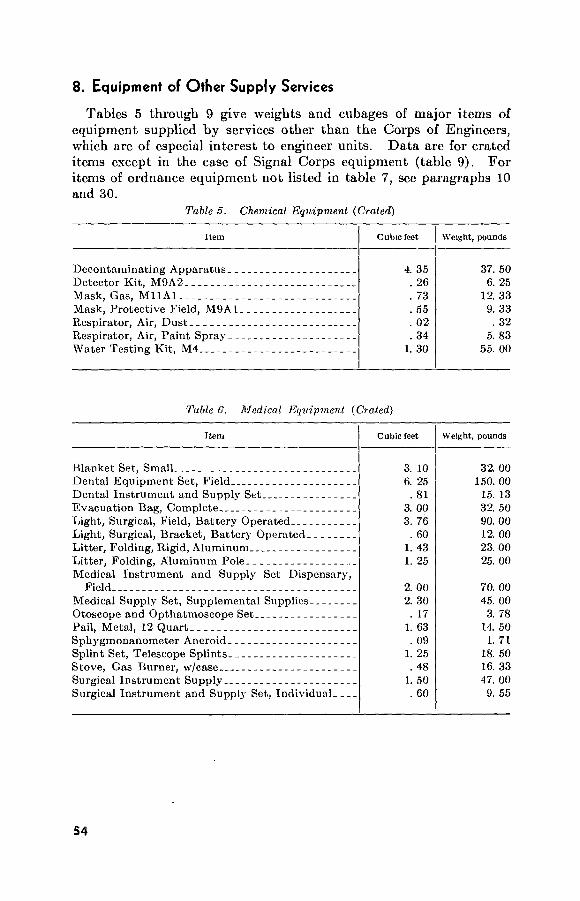
8. Equipment of Other Supply Services
Tables 5 through 9 give weights and cubages of major items of equipment supplied by services other than the Corps of Engineers, which are of especial interest to engineer units. Data are for crated items except in the case of Signal Corps equipment (table 9). For items of ordnance equipment not listed in table 7, see paragraphs 10 and 30.
Table 5. Chemical Equipment (Crated)
Item Cubic feet
4. 35 26 73 55 02 34
1. 30
Weight, pounds
Decontaminating Apparatus. _. Detector Kit, M9A2 Mask, Gas, MllAl Mask, Protective Field, M9A1_ Respirator, Air, Dust Respirator, Air, Paint Spray Water Testing Kit, M4
37. 50 6. 25
12. 33 9. 33
. 32 5. 83
55. 00
Table 6. Medical Equipment (Crated)
Item Cubic feet
3. 10 6. 25
81 3. 00
id 60
1. 43 1. 25
2. 00 2. 30
. 17 1. 63
. 09 1. 25
. 48 1. 50
. 60
Weight, pounds
Blanket Set, Small Dental Equipment Set, Field Dental Instrument and Supply Set Evacuation Bag, Complete Light, Surgical, Field, Battery Operated Light, Surgical, Bracket, Battery Operated Litter, Folding, Rigid, Aluminum Litter, Folding, Aluminum Pole Medical Instrument and Supply Set Dispensary,
Field Medical Supply Set, Supplemental Supplies Otoscope and Opthatmoscope Set Pail, Metal, 12 Quart Sphygmonanometer Aneroid Splint Set, Telescope Splints Stove, Gas Burner, w/case Surgical Instrument Supply Surgical Instrument and Supply Set, Individual
32. 00 150. 00
15. 13 32. 50 90. 00 12. 00 23. 00 25. 00
70. 00 45. 00
3. 78 14. 50
1. 71 18. 50 16. 33 47. 00
9. 55
54

Table 7. Ordnance Equipment (Crated)
Item Cubic feet Weight, pounds
Cabinet, Spare Parts Type III, C1B Chain Assembly, Sglc Leg, % in. by 16 ft Demounter, Pneumatic Tire, Hydraulic Mount, Machine Gun, Cal. 30, M48, W/EQP Mount, Machine Gun, AA, Cal. 50, M63, W/EQP.. Mount, Tripod, Machine Gun, Cal. 30, M2, W/EQP. Mount, Tripod, Machine Gun, Cal. 50, M3, W/EQP. Mount, Tripod, Machine Gun, 7.62 MM, M91 Mount, Truck, Pedestal, M24A2 Tool Kit, Armorers Tool Kit, Automotive Fuel and Elec Sys Rpmn Tool Kit, Electricians No. 1 Tool Kit, Electricians No. 2 Tool Kit, General Mechanics Tool Kit, Instrument Repairman Tool Kit, Metal Body Repairman Tool Kit, Organizational Maintenance No. 1 Com-
mon Tool Kit, Organizational Maintenance No. 1 Supple-
mental Tool Kit, Organizational Maintenance No. 2 Com-
mon Tool Kit, Organizational Maintenance No. 2 Supple-
mental Tool Kit, Organizational Maintenance Set No. 7 Tool Set, Machinist Tool Set, Organizational Maint Army Aircraft
29. 75 . 50
10. 60 2. 40 8. 10 1. 90 2. 00 2. 00
10. 60 2. 42 1. 61 4. 74
. 35 2. 00 1. 81
. 76
41. 70
36. 80
276. 00
130. 80 65. 00
1. 33 59. 00
378. 00 70. 00
300. 00 65. 00
170. 00 25. 00 44. 00 40. 00
253. 00 48. 00 22. 45 82. 28 13. 00 69. 00 50. 36 37. 50
858. 00
871. 00
2, 425. 00
3, 076. 00 935. 00
48. 00 930. 00
Table 8. Quartermaster Equipment (Crated)
Item Cubic feet Weight, pounds
Bag, Water Sterilizing Bag, Ammunition Calculating Machine Can, A-G, 10 gal. cap Can, A-G, 24 gal. cap Can, A-G, 32 gal. cap Can, Water, 5 gal Chest, Music, Fiber Cooking Outfit, 1 brn Desk, Field, type 11 Duplicating Machine, Hand Opr.. Duplicating Machine, Mtr. Dvn__ Duplicating Machine, Spirit Proc. Lantern, Gas, lyi pt Machine, Computing, 10 Column. Paulin, Duck, OD, 20 by 40 ft Paulin, Duck, OD, 12 by 17 ft
1. 34 . 08
1. 04 1. 01 3. 32 4. 57
. 94 2. 89
. 26 4. 28
12. 65 28. 63
2. 98 . 64
3. 08 4. 90 1. 65
20. 40 2. 00
35. 00 13. 83 26. 67 32. 33 10. 00 26. 00
5. 17 54. 00
204. 00 326. 00
65. 00 9. 37
65. 00 192. 00 50. 67
55

Table 8. Quartermaster Equipment (Crated)—Continued
Item Cubic feet
18. 50 3. 49 5. 89 4. 08 1. 42
. 19 11. 14
. 51 4. 13 5. 21 4. 90 8. 39 1. 50
Weight, pounds
Range, Field, M1937B Pack Roll, Commissary, Complete Safe, Field Scale, Plat, 300 lb Screen, Latrine, Complete Sling, Flagstaff Stencil Cutting Machine, 1 in Stencil Outfit Typewriter, Non-Ptbl, 11 in Typewriter, Non-Ptbl, 14-15 in._ Typewriter, Non-Ptbl, 18-19 in_- Typewriter, Non-Ptbl, 26-27 in__ Typewriter, Ptbl w/carrying case.
340. 00 65. 00
185. 00 134. 00
45. 00 3. 19
190. 00 65. 50 76. 00 60. 00 80. 00
125. 00 32. 00
Table 9. Signal Equipment (Uncrated)
Item
Amplifier, AM-598/U Axle, RL-27 Battery, BB-50 Camera, PH-324 Camera, PH-691/U Camera, KS-7 Channel Alignment Indicator ID-292/PRC- Chest, BC-5 Chest, CY-250/U Chest Set, H-12/GT Chest Set, H-18/GT Code Tr’ng Set AN/GSC-Tl Coil, C-161 Converter, M209 Electronic Multimeter TS-505/U Emergency Switchboard SB-18/GT Exposure Meter PH-260 Flashlight MX-212/U Flashlight MX-991/U Frequency Meter SCR-211 Hand Set TS-10 Head Set HS-30 Linemen’s Equipment TE-21 Microphone Multimeter AN/PRM-15 Oscilloscope OS-8/U Photo Equipment PH-383 Power Unit PE-162 Radiac Meter IM-93/UD Radio Set AN/GRC 9
Cubic feet
0. 94 . 12 . 50 . 02 . 46
64. 00 . 02
3. 78 6. 58
. 04
. 20 1. 31
. 13
. 08
. 34
. 09
. 01 . 01 . 02 . 96 . 20 . 04 . 96 . 01 . 12 . 43
10. 00 1. 91
. 01 17. 00
Weight, pounds
35. 95 5. 50
64. 00 . 94
15. 00 292. 00
1. 30 35. 00 35. 00
2. 22 3. 40
40. 00 3. 00 6. 00
15. 00 2. 25 1. 00
. 50
. 06 39. 50
1. 90 . 57
21. 00 . 09
5. 00 14. 50
333. 00 56. 00
. 07 135. 00
56

Table 9. Signal Equipment {Uncrated)—Continued
Item Weight, pounds
Radio Set AN/PRC 10 Radio Set AN/PRC 6 Radio Set AN/VRC 10 Radio Sot AN/VRC 8 Radio Set AN/VRC 16 Radio Set SCR-193 Radio Set AN/GRA Radio Receiving Set AN/TRR-8 Reel Equipment CE-11 Reel Unit RL-31 Spool DR-8 Switch Board SB-22/PT Telephone Set TA 264/PT Telephone Set TA 312/PT Telephone Central Office Set TC-4. Teletypewriter Set AN/PGC-1 Terminal Telegraph Test Set TS-26/TSM Test Set Electron Tube TV-7/U Timer Interval EM 17 Tool Equipment TE 33 Tool Equipment TE 41 Tool Equipment TK 28/CF Tube Tester Vibrator Pack PP-68/U Wire pike Wire WD-l/TT on Reel DR-4 Wire WD-l/TT on Reel DR-5 Wire WD-l/TT on Spool DR-8
18. 00 3. 50
138. 00 138. 00 138. 00 114. 00
17. 50 26. 00 17. 00
100. 00 2. 00
37. 10 25. 00
. 18 440. 40 451. 00
51. 00 8. 00
18. 00 2. 00 3. 00
16. 00 17. 00 41. 00 22. 00
6. 00 70. 00 82. 00 14. 00
Section II. MOTORIZED AND HEAVY EQUIPMENT
9. Engineer Motorized and Heavy Equipment
The make, model, stock number, overall dimensions, weight in pounds, and cubage of the various items of engineer motorized and other heavy equipment, and the aircraft in which they are trans- portable, are given in table 10. Data are for working conditions.
57
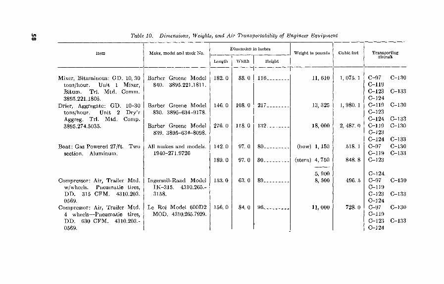
tn oo Table 10. Dimensions, Weights, and Air Transportability of Engineer Equipment
Item
Mixer, Bituminous: GD. 10, 30 tons/hour. Unit 1 Mixer, Bitum. Trl. Mtd. Comm. 3895.221.1805.
Drier, Aggregate: GD. 10-30 tons/hour. Unit 2 Dry’r Aggreg. Trl. Mtd. Comp. 3895.274.5035.
Boat: Gas Powered 27/ft. Two section. Aluminum.
Compressor: Air, Trailer Mtd. w/wheels. Pneumatic tires, DD. 315 CFM. 4310.203. 0569.
Compressor: Air, Trailer Mtd. 4 wheels—Pneumatic tires, DD. 630 CFM. 4310.203.- 0569.
Make, model and stock No. Dimension in inches
Length Width Height
Weight in pounds Cubic feet Transporting aircraft
Barber Greene Model 840. 3895.221.1811.
Barber Greene Model 830. 3895-634-9178.
Barber Greene Model 839. 3895-634-8098.
All makes and models. 1940-271.9726
Ingersoll-Rand Model IK-315. 4310.265.- 3158.
Le Roi Model 600D2 MOD. 4310.265.7929.
182. 0
146. 0
276. 0
142. 0
189. 0
153. 0
156. 0
88. 0
108. 0
118. 0
97. 0
97. 0
63. 0
84. 0
116.
217.
132.
80..
80. .
89_
96_
11, 610
13, 325
18, 000
(bow) 1, 150
(stern) 4, 750
5, 900 8, 500
11, 000
1, 075. 1
1, 980. 1
2, 487. 0
518. 1
848. 8
496. 5
728. 0
C-97 C-119 C-123 C-124 C-119 C-123 C-124 C-119 C-l 23 C-124 C-97 C-119 C-123
C-124 C-97 C-119 C-123 C-124 C-97 C-119 C-123 C-124
C-l 30
C-133
C-130
C-133 C-130
C-133 C-130 C-133
C-130
C-133
C-130
C-133
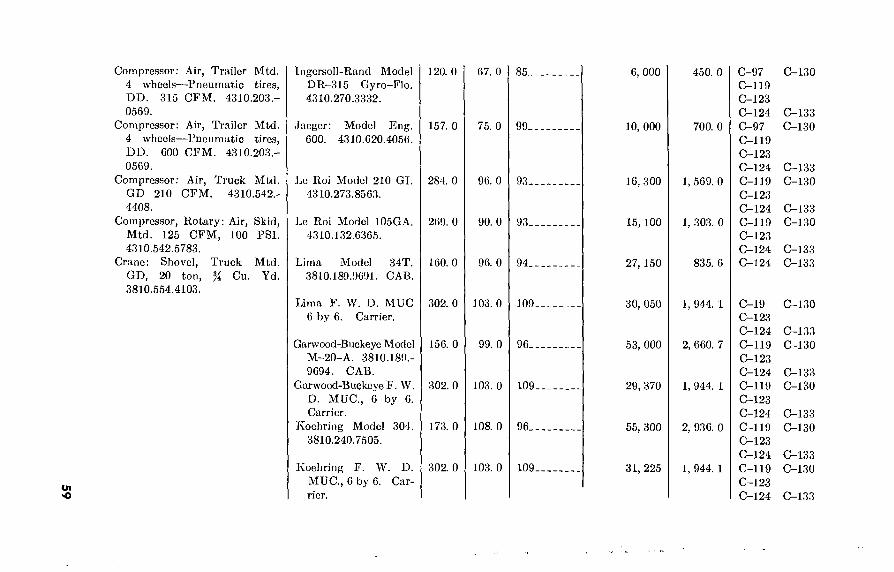
Ul
«o
Compressor: Air, Trailer Mtd. 4 wheels—Pneumatic tires, DD. 315 CFM. 4310.203.- 0569.
Compressor: Air, Trailer Mtd. 4 wheels—Pneumatic tires, DD. 600 CFM. 4310.203.- 0569.
Compressor: Air, Truck Mtd. CD 210 CFM. 4310.542.- 4408.
Compressor, Rotary: Air, Skid, Mtd. 125 CFM, 100 PSI. 4310.542.5783.
Crane: Shovel, Truck Mtd. GD, 20 ton, 3810.554.4103.
Cu. Yd.
Ingersoll-Rand Model DR-315 Gyro-Flo. 4310.270.3332.
Jaeger: Model Eng. 600. 4310.620.4056.
Le Roi Model 210 GI. 4310.273.8563.
Le Roi Model 105GA. 4310.132.6365.
Lima Model 34T. 3810.180.9691. CAB.
Lima F. W. D. MUC 6 by 6. Carrier.
Garwood-Buckeye Model M-20-A. 3810.189.- 9694. CAB.
Garwood-Buckeye F. W. D. MUG., 6 by 6. Carrier.
Koehring Model 304. 3810.240.7505.
Koehring F. W. D. MUC., 6 by 6. Car-
120. 0
157. 0
284. 0
269. 0
160. 0
302. 0
156. 0
302. 0
173. 0
302. 0
67. 0
75. 0
96. 0
90. 0
96. 0
103. 0
99. 0
103. 0
108. 0
103. 0
85_
99.
93.
93.
94.
109.
96.
109.
96.
109.
6, 000
10, 000
16, 300
15, 100
27, 150
30, 050
53, 000
29, 370
55, 300
31, 225
450. 0
700. 0
1, 569. 0
1, 303. 0
835. 6
1, 944. 1
2, 660. 7
1, 944. 1
2, 936. 0
1, 944. 1
C-97 C-119 C-123 C-124 C-97 C-119 C-123 C-124 C-119 C-123 C-124 C-119 C-123 C-124 C-124
C-19 C-123 C-124 C-119 C-123 C-124 C-119 C-123 C-124 C-119 C-123 C-124 C-119 C-123 C-124
C-130
C-133 C-130
C-133 C-130
C-133 C-130
C-133 C-133
C-130
C-133 C-130
C-133 C-130
C-133 C-130
C-133 C-130
C-133

O' o Table 10. Dimensions, Weights, and Air Transportability of Engineer Equipment—Continued
Item
Gran e—Contin ued
Crane: Non-revolving, Tractor Oper. Wheeled, 40,000 Cap. 20 ft. Boom. 3810.234.5118.
Crusher, Jaw: Rock, Airborne. 15 TPH Capacity. 3820.286. 9190.
Distributor: Bituminous Mat’l. Trailer Mounted. 1,250 Gal. 3895.194.5927.
Distributor: Bituminous Mat’l. Truck Mounted. 800 Gal. 3895.663.4680.
Distributor: Water. Truck Mounted. 1,000 Gal. 3825.- 275.2622.
Dimension In Inches Make, model and stock No. Weight In pounds Cubic feet Transporting
aircraft Length Width
Bucyrus Erie Model 147. 0 96. 0 22B. 3810.189.9692. CAB.
Bucyrus Erie F.W.D. 302. 0 MUC,, 6.by 6. Carrier.
Le Tourneau Model M- 330. 0
103. 0
115. 0 20. 3810.234.5119.
Iowa Unit. 3820.030.1612 Iowa Unit. AB-1524- SP-15T.
Entyre Model MX, Style RE. 3895.- 194.5937.
Entyre Model MX, Style RE. 3895.641.6025.
Rosco Model MDE. 3825.383.7133.
Tank Assem Chassis
224. 0
194. 0
328. 0
266. 0
140. 0 260. 0
80. 0
92. 0
96. 0
97. 0
97. 0 94. 0
Height
94..
109.
230
21, 090
26, 100
8, 400
767. 7
1, 944. 1
5, 051. 2
92 16, 000 954. 0
102. 11, 500 1, 053. 5
99 22, 300 1,804. 0
105
82. 105
19, 820 1, 567. 8
644. 4 1,485. 1
2, 129. 5
C-119 C-123 C-124 C-119 C-123 C-124 C-97 C-119 C-123 C-124 C-97 C-119 C-123 C-124 C-119 C-123 C-124 C-119 C-123 C-124 C-119 C-123 C-124
C-130
C-133 C-130
C-133 C-130
C-133 C-130
C-133 C-130
C-133 C-130
C-133 C-130
C-133

Generator Set: Portable, Diesel. Skid Mounted, 15 KW., 127-220 Volt, 3 phase, 60 cycle or 230-400 Volt, 3 phase, 50 cycle. 6115.235.8681.
Generator Set: Portable, Diesel, Engine-Driven, Skid Mount- ed, 30 KW., 127-220 Volt, 3-phase, 60 cycle, or 230-400 Volt, 3 phase, 50 cycle. 61.16.635.9955.
Grader: Road, Motorized, Die- sel, 12 ft. Mold Board. 3805.238.5108.
Kettle: Asphalt, Repair, Trailer Mounted \v/Motor Driven Hand Spray, 110 Gal. capac- ity. 3895.247.7592.
Kettle: Asphalt, Repair, Trailer Mounted w/Motor Driven Hand Spray, 165 Gal. capac- ity. 3895.247.7592.
Kettle: Asphalt, Skid Mounted, w/Gas Powered Circulating Pump, 750 Gal. capacity. 3895.292.0078.
Ready Power Model RD-6-A 12. 6115.236.9995.
Buda Model 6DTG-317. 6115.242.2295.
Caterpillar Model 12. 3805.261.5826.
Austin-Western Model 99H. 3805.261.5825.
Littleford Model US-66. 3895.247.7591.
Littleford Model 84-HD-3. 3895.247.7594.
Rosco Model KO. 3895.252.-1183.
84. 0
91. 0
310. 0
291. 0
116. 0
132. 0
152. 0
30. 0
25. 0
97. 0
95. 0
53. 0
64. 0
85. 0
53- 3, 455 77. 3
50. 2, 995 65. 8
91-
104-
46-
23, 320
22, 000
1, 262
1,'583. 5
1, 663. 8
163. 7
65. 1,500 317. 7
54. 6, 500 403. 7
C-97 C-119 C-123 C-124
C-97 C-119 C-123 C-124
C-119 C-123 C-124 C-119 C-123 C-124 C-97 C-119 C-123 C-124 C-97 C-119 C-123 C-124 C-97 C-119 C-123 C-124
C-130
C-133
C-130
C-133
C-130
C-133 C-130
C-133 C-130
C-133 C-130
C-133 C-130
C-133

o» Kî
Table 10. Dimensions, Weights, and Air Transportability of Engineer Equipment—Continued
Item Make, model and stock No.
Lubricator: 1% ton, Trailer Mounted.
Grey Mfg. Co. No stock number.
Mixer: Concrete, Gas Driven, Trailer Mounted, Side Dis- charge, 4 wheels, 14 cu. ft. 3895.286.1145.
Mixer: Concrete, Gas Driven, Air Cooled, End Discharge, Trailer Mounted, 4 Pneu- matic Tired Wheels, 16 cu. ft. 3895.238.5094.
Roller: Road, Towed Type, Sheeps Foot, 2 Drums, in line. 3895.263.0121.
Ransome Model 14 SU. 3895.264.4810.
Construction Mach. Co. Model 16S. 3895.255.4134.
Le Tourneau Model W-2. 3895.250.6054.
Roller: Road, Towed Type, Wheeled, 13 Pneumatic Tires. 3895.227.1599.
William Bros. Model 67W. 3895.243.5442.
Roller, 7}4 Ton: Road, Towed Type, Wheeled, 4 Pneumatic Tires. 3895.641.7761.
Grace Model Wltr. 3895.243.2678.
William Bros. Model 450 Mod. 3895.- 223.8412.
Dimension in Inches
Lengtli W idth Height
167. 0
121. b
115. 0
175. 0
174. 0
288. 0
298. 0
84. 0
88. 0
98. 0
113. 0
89. 0
96. 0
96. 0
88-
120.
127-
58.
46-
92-
92-
Weight in pounds
5, 700
5, 970
5, 780
6, 040
3, 550
19, 000
14, 800
Cubic feet Transporting aircraft
714. 4
739. 4
828. 3
C-97 C-130 C-119 C-123 C-124 C-133 C-97 C-l 30 C-119 C-123 C-124 C-133 C-119 C-130 C-123 C-124 C-133
663. 7
412. 2
1, 472. 0
1, 523. 1
C-97 C-130 C-119 C-123 C-124 C-133 C-97 C-130 C-119 C-123 C-124 C-133 C-119 C-130 C-123 C-124 C-133 C-119 C-130 C-123 C-124 C-133
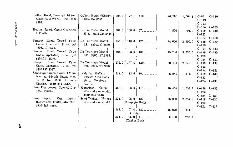
OO
'JK
KS
a o
cn
Boiler: B.oad, Powered, 10 ton, Gasoline, 3 Wheel. 3959.223. 8397.
Galion Model “Chief”. 3895.194.8555.
Kooter: Road, Cable Operated, 3 Tooth.
Le Tourneau Model H-3. 3895.234.2545.
Scraper: Road, Towed Type, Cable Operated, 8 cu. yd. 3805.197.8574.
Scraper: Road, Towed Type, Cable Operated, 12 cu. yd. 3805.261.5849.
Scraper: Road, Towed Type, Cable Operated, 12 cu. yd. 3805.197.8582.
Shop Equipment: Contact Main- tenance, Mobile Shop, Mtd. on % ton M56 Ordnance Chassis. 4940-294-9518.
Shop Equipment: General Pur- pose, Truck.
Shop Equip.: Org. Repair, Heavy, semi trailer, Mounted. 4940-287-4894.
Le Tourneau Model LS. 3805.197.8579.
Le Tourneau Model LP. 3805.197.8584.
Le Tourneau Model FU. 3805.378.9807.
Body by: McCare Powers Auto Body Shop. No stock number.
Motorized. No spe- cific make or model. 4940-294-9516.
Semi-Trailer. No spe- cific make or model.
O' u
205. 0 77. 0 110. C-130
204. 0
355. 0
384. 0
376. 0
214. 0
100. 0
118. 0
123. 0
137. 0
83. 0
67..
120.
133.
130.
89_.
268. 0 93. 0 115.
324. 0 95. 0 129. (Complete Unit)
252.0 97.0 88.. (Body)
324. 0 I 95. 0 I 41.. (Trailer Bed)
20, 200
7, 500
14, 000
19, 700
20, 400
8, 980
16, 455
23, 000
16, 870
6, 130
1, 004. 8
791. 0
2, 909. 0
3, 635. 3
2, 875. 3
914. 8
1, 658. 7
2, 297. 8
1, 244. 8
730. 3
C-97 C-119 C-123 C-124 C-119 C-123 C-l-24 C-119 C-123 C-124
; C-119 C-123 C-124 C-119 C-123 C-124
' C-119 C-123 C-124
C-119 C-123 C-124 C-119 C-123 C-124
C-133 C-130
C-133 C-130
C-133 C-130
C-133 C-130
C-133 C-130
C-133
C-130
C-133 C-130
C-133

Table ¿0. Di?nensions, Weights, and Air Transportability of Engineer Equipment—Continued
Item Make, model and stock No. Dimension in inches
Length Width Height
Weight in pounds Cubic feet Transporting aircraft
Scraper: Road, Motorized, Cable Operated, 11 to 12 cu. yd. 3805.276.7616.
Roller: Road, G.D., Tandem, 3 Axle 9-14 ton. 3895.194.8544.
Sawmill: Portable, G.D., Head Block Type, 4 by 7 ft., 60 in. Diameter Saw. 3210.287.4144.
Tractor: Wheel, Pneumatic, Diesel, Special, 20,025-27,000 DBP. 2420.190.0325.
Shovel: Front, for Crane Shovel Truck Mtd., 20 ton, % yd.
Le Tourneau Model Super C Tournapull.
w/Model LP Carryall. 3805.281.1892.
Buffalo-Springficld Model KX-16. 3895.194.8544.
Galion Model 3T9G. 3895.641.6414.
Corinth Model 2C. 3210.242.4493.
Le Tourneau Model Super C Tourna- dozer. 2420.277.- 9593.
Lima. 3815.227.6245 __ Garwood-Buckeye.
3815.641.7478. Kocring. 3815.246.
4403.
155. 0
264. 0
268. 0
248. 0
95. 0
122. 0
63. 0
67. 0
90,
142.
87.
85.
204. 0
266. 0 216. 0
247. 0
121. 0
39. 0 39. 0
51. 0
100.
65. 65.
50.
13, 400
19, 500
18, 770
21, 539
25, 860
31, 700
6, 500 6, 340
6, 480
766. 9
2, 646. 7
850. 1
817. 3
1, 428. 5
390. 2 316. 9
364. 5
C-119 C-123 C-124 C-119 C-123 C-124 C-97 C-119 C-123 C-124 C-97 C-119 C-123 C-124 C-97 C-119 C-123 C-124 C-124
C-97 C-119 C-123 C-124
C-130
C-133 C-130
C-133 C-130
C-133 C-130
C-133 C-130
C-133 C-130 C-133
C-130

Dolly
O' Ul
Tank: Alphalt, Steel, Trailer Mounted, w/Steam Coils, 1,500 gal. 2330.294.6509.
Tractor: Crawler, Diesel, 8,600- 12,000 DBF, w/Bulldozer Tilt, Hydraulic Front Mtd., Winch, Towing, Reversible, rear, 1 Drum. 2410.260.3944.
Tractor, Crawler Type, Diesel Driven, 12,000-1,700 Lbs. DBF, w/Bulldozer Tilt, Power Control Unit, Fr. Mtd., Winch Reversible, Rear Mtd., 1 Drum.
Tractor: Crawler Type, Diesel Driven, 17,000-24,000 Lbs. DBF, w/Angle Dozer, Power Control Unit, Front Mtd. Cable, Operating, 1 Drum & Winch Reversible, Rear Mounted, 1 Drum.
Tractor: Crawler Type, Diesel Driven, 28,100-38,000 Lbs. DBF, w/Bulldozer, Tilting, Cable Oper, Power Control Unit, Cable Operating, Front Mtd., 1 Drum, Power Control Unit, Cable Operating, Rear Mounted, 2 Drums.
Bucyrus-Eric. 3815.227.6233.
Eidel-Model Efld-40. 2330.188.0088.
Assem. Totals Little Ford Model 102
S. 2330.391.0521.
Caterpillar, Model D4
Caterpillar Model D6. 2410-190-0044.
Caterpillar Model D7. 2410.268.8634.
Caterpillar Model D8 2-U Scries. 2410.233.5751 and Model D89A Scries. 2410.542.4881, 2410. 542.4882.
234. 0 433. 1 C-133
104. 0
480. 0 231. 0
144. 0
190. 0 (Blade)
219. 0
236. 0
236. 0
39. 0
115. 0
115. 0 96. 0
99. 0
142. 0 (Str.)
152. 0
82,
57.
77__ 114.
70.
76.
160. 0
160. 0
6, 340
8, 650
32, 550 10, 130
16, 062
22, 755
90
90
35, 676
46, 787
53, 175
394. 5
2, 459. 7 1, 463. 0
577. 5
1, 186. 6
1, 858. 6
1, 966. 7
1, 966. 7
C-124 C-130 C-133
C-119 C-130 C-123 C-124 C-133 C-97 C-130 C-119 C-123 C-124 C-133
C-97 C-130 C-119 C-123 C-124 C-133
C-119 C-130 C-123 C-124 C-133
C-124 C-130
C-133
C-124 C-130 C-133

o. o>
Table 10. Dimensions, Weights, and Air Transportability of Engineer Equipment—Continued
Item Make, model and stock No. Dimension in indies
Length Width Height
Weight in pounds Cubic feet Transporting aircraft
Tractor: 4 Wheels, Rubber Tired, DED, 27,022-38,000 lbs. DBF, Power Control Unit, 2 Drums. 2420.200. 1297.
Tractor: Wheeled, Rubber Tired, Industrial, DED, 20.025- 27,000 lbs. DBF, Cable operated, Rear Mount- ed, 2 Drums, Weight Transfer Device. 2420.287.5256.
Tractor: Wheeled, Rubber Tired, Industrial, DED, 14.025- 20,000 lbs. DBF. 2420.517.0675.
Tractor: Crawler Type 8,600- 12,000 lbs. DBF, w/Loader Hydraulic Operated, Front Dump, % on. yd. Bucket.
Trailer: 4 wheel, Tandem, 4 ■ Double Tire, Flat Bed, for
Crane Shovel Attachment, 10 ton.
Trailer: Full Low Bed, 8 ton
Caterpillar DW20M. 2420.200.1297.
MRS 190. 2420.287.5250.
MRS 150. 2420.517.0675.
Allis-Chalmers Model HD-5G. 2410.229.9459.
All makes and models. 2330.377.0389.
All makes and models. 2330.273.4421.
229. 5
194. 0
194. 0
174. 0
335. 0
287. 0
112. 4
100. 0
96. 0
73. 0
98. 0
103. 0
Reducible to 114.5.
Reducible to 96.
115.
71.5-
60.
57.
49, 020
29, 000
Unknown
16, 540
11, 750
9, 680
1, 923. 0
1, 451. 9
Unknown
525. 6
1, 139. 9
975. 1
C-119 C-123 C-124 C-130 C-133 C-119 C-123 C-124 C-130 C-133
C-119 C-123 C-124 C-130 C-133 C-97 C-130 C-119 (>123 C-124 C-133 C-119 C-123 C-124
C-130
C-133
C-119 C-130 C-123 C-124 C-133

96. O Trailer: Dump, 7-8 cu. yd., For Tractor, Air Transport- able, Wheel Type, 7,800 to 14,000 lb., DBF, w/Weight Transfer Device.
Tractor, Saw, Power Unit, Wheelbarrow type, G.D. 3750.275.000.
Spreader: Aggregate, Towed, Traction Powered, 8 ft. width.
Tank: Water, Steel, Semi- Trailer, Mounted, 1,500 gal. 2330.271.9947.
Pump: Water, Trailer Mounted w/Distributor Attachments. 3825.263.2975.
Pump: Water, Centrifugal, G.D., Trailer Mtd., 4 in. discharge, 4 in. suction, 500 GPM @ 20 ft. head, Normal discharge. 4320.289.3699.
Truck: Bolster Body, 2^ ton, 6 by 6 with Front Mtd. Winch.
Water Purification Equipment: Diatomite #3, Set #3, Port- able, 35 GPM.
M-R-S Model 75 A GW. 2805.227.0482.
318. 0
Little Giant Model 22-4. 3750.275.000.
133. 0
Good Roads Machin- ery Co. Model 8. 3895.223.8210.
107. 0
Columbian Steel 220. 0 Tank Co. 2330.368.2818.
Rosco Model MAE. 180. 0 3825.269.2976.
Carver Model 4822. 4320.289.3699.
48. 0
GMC Model CCKW- 353. 2320.287.4249.
268. 0
4610.190.0300.
38.0
45. 0
96. 0
78. 0
37. 0
87. 0
O' Nl
115 boxes, 3 chests, and 3 unboxed Items will be carried as part of loads in trucks, rollers, etc.
10, 400 1, 590. 0
1, 080 105. 3
1, 550 103. 1
7, 000 1, 100. 0
2, 200 593. 1
800 52.4
11, 400 1, 295. 3
3, 800 (uncrated)
5,200 (for export)
G-119 C-123 C-124
C-97 Ç-119 C-123 C-124 C-97 C-119 C-123 C-124 C-119 C-123 C-124 C-97 C-119 C-123 C-124 C-97 C-119 C-123 C-124
C-97 C-119 C-123 C-124
C-130
C-133
C-130
C-133 C-130
C-133 C-130
C-133 C-130
C-133 C-130
C-133
C-130
C-133

o oo Table 10. Dimensions, Weights, and Air Transportability of Engineer Equipment—Continued
Item
Bridge: Floating M-4. 5420-267-0011.
Typical truckloads
Required LD
28
12
D
H
Load name
Shallow Water Acces- sories.
I’ontons
Approach Accessories.
Abutment Equipment-.
Trestles .
Ferry Equipment-
Spare Components.
Floats and Saddles
Dimension in inches
Length Width Height
178
367
180
180
180
180
180
144
78
87
70
79
78
78
78
78
49
58
62
46
55
35
74
51
Weight in pounds
4, 505
10, 359
7, 850
8, 007
11, 954
5, 346
14, 121
7, 512
Cubic feet
393. 7
1, 071. 7
510. 2
378. 5
446. 9
284. 4
601. 3
331. 5
Transporting aircraft
C-119 C-123 C-124 C-119 C-123 C-124 C-119 C-123 C-124 C-119 C-123 C-124 C-119 C-123 C-124 C-119 C-123 C-124 C-119 C-123 C-124 C-119 C-123 C-124
C-130
C-133 C-130
C-133 C-130
C-133 C-130
C-133 C-130
C-133 C-130
C-133 C-130
C-133 C-130
C-133
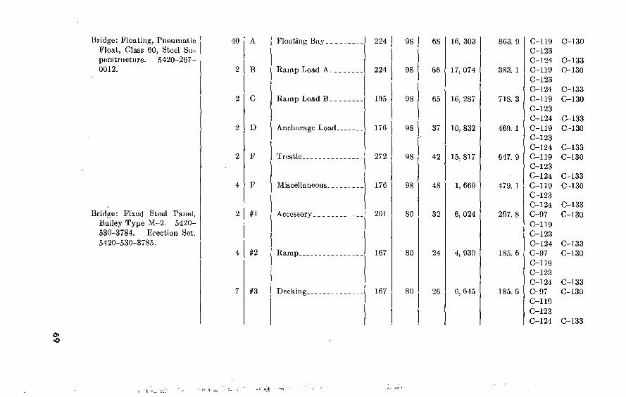
Bridge: Floating, Pneumatic
Float, Class 60, Steel Su-
perstructure. 5420-267- 0012.
Bridge: Fixed Steel Panel,
Bailey Type M-2. 5420-
530-3784. Erection Set.
5420-530-3785.
40
D
#1
§2
§3
Floating Bay
Ramp Load A. _
Ramp Load B_.
Anchorage Load
Trestle
Miscellaneous--.
Accessory
Ramp
Decking.
224
224
195
176
272
176
201
167
167
98
98
98
98
98
98
80
80
80
68
66
65
37
42
48
32
24
26
16, 303
17, 074
16, 287
10, 832
15, 817
1, 669
6, 024
4, 939
6, 645
863. 9
383. 1
718. 3
469. 1
647. 9
479. 1
297. 8
185. 6
185. 6
C-119 C-123 C-124
C-119
C-123
C-124
C-119
C-123
C-124
C-119
C-123
C-124
C-119 C-123 C-124
C-119
C-123 C-124
C-97
C-119
C-123
C-124 C-97
C-119
C-123 C-124 C-97
C-119
C-123 C-124
C-130
C-133
C-130
C-133
C-130
C-133 C-130
C-133 C-130
C-133
C-130
C-133
C-130
C-133
C-130
C-133 C-130
C-133

•jr^ '"T'* ï>-»-f7r
N O
Table 10. Dimensions, Weights, and Air Transportability of Engineer Eguipmenl Continued
Item Typical truckloads
Required
14
LD
u
#5
#6
#7
Load name
Panel.
Transom.
Footwalk.
Grillage.
Dimension in inehes
Length
124
240
120
163
Width
75
80
80
80
Height
62
16
33
12
Weight in pounds
5, 791
5, 336
3, 058
3, 744
Cubic feet
333. 7
177. 8
183. 3
90. 6
Transporting aircraft
C-97 C-130 C-119
, C-123 C-124 C-133 C-97 C-130 C-119 C-123 C-124 C-133 C-97 C-130 C-119 C-123 C-124 C-133 C-97 C-130 C-119 C-123 C-124 C-133
i.
4
■i
i
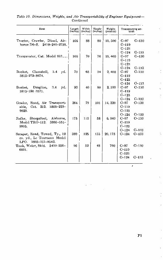
Table 10. Dimensions, Weights, and Air Transportability of Engineer Equipment—
Continued
Item
Tractor, Crawler, Diesel, Air- borne D6-S. 2410-240-2738.
Traxcavator, Cat. Model 933-
Bucket, Clamshell, 3.4 yd. 3815-272-8674.
Bucket, Dragline, 3.4 yd. 3815-186-3571.
Grader, Road, Air Transport- able, Cat. 212. 3805-223- 9029.
Roller, Sheepsfoot, Airborne, Model TRO-112. 3895-351- 9805.
Scraper, Road, Towed, Ty., 12 eu. yd., Le Tourneau Model LPO. 3805-351-9542.
Tank, Water, Skid. 5430-256- 6601.
Length (Inches)
166
166
70
90
264
175
389
96
Width (inches)
88
70
65
40
79
115
125
52
Height (Inches)
80
76
34
60
101
58
133
48
Weight (pounds)
15, 500
15, 400
2, 400
2, 100
14, 220
6, 040
20, 175
760
Transporting air- craft
C-97 C-119 C-123 C-124 C-97 C-119 C-123 C-124 C-97 C-119 C-123 C-124 C-97 C-119 C-123 C-124 C-97 C-119 C-123 C-124 C-97 C-119 C-123 C-124 C-124
C-130
C-133 C-130
C-133 C-130
C-133 C-130
C-133 C-130
C-133 C-130
C-133 C-133
C-130 C-97 C-119 C-123 C-124 C-133
71

10. Ordnance Vehicles The overall dimensions, volumes in measurement tons, and net
weights of certain ordnance vehicles issued to engineer units are given in table 11.
Table IT Ordnance Vehicles Issued to Engineer Troop Units
Vehicle Dimensions (inches)
Length Width Height
Measure- ment tons
Net weight, pounds
Trailer, cargo, %-ton, 2-wheel Trailer, amphibious cargo, yi-ton,
2-wheel Trailer, cargo, %-ton, 2-wheel
(M101) Trailer, cargo, 1%-ton, 2-wheel
(M104) Trailer, water-tank, V/o-ton, 2-
wheel (M106) Truck, utility, J4-ton, 4 by 4 (M38,
Willys) Truck, pickup, %-ton, 4 by 2
(Chevrolet) Truck, cargo, %-ton, 4 by 4 (M37,
Dodge) Truck, command, %-ton, 4 by 4
(M42) Truck, ambulance, %-ton, 4 by 4
(M43) Truck, stake and platform, l^-ton,
4 by 2 (Chevrolet) Truck, cargo, 2^-ton, 6 by 6 LWB
(CMC) Truck, cargo, 2H-ton, 6 by 6,
LWB, WW (CMC) Truck, dump, 2^-ton, 6 by 6
(M47) Truck, gasoline tank, 2)4-ton, 6 by
6, 750-gal (CMC) Truck, gasoline-tank, 2)^-ton, 6
by 4, 1,350-gal Truck, shop van, 2J4-ton, 6 by 6
(M535) Truck, stake and platform, 2%-
ton, 4 by 2 (International Har- vester)
Truck, water-tank, 2%-ton, 6 by 6, 700-gal (CMC)
Truck, cargo, 5-ton, 6 by 6, LWB, WW (M41)
Truck, dump, 5-ton, 6 by 6 (M51)_.
See footnotes at end of table.
108'A
108 A
1433/4
165A
166%
133
197
189%
184%
198%
265
256ki
270%
235%
253%
288
255%
276%
253%
309% 266%
56%
56
73%
83
2 93
62
75
73%
73%
73%
87%
88
88
85
91
92
96
92%
90
96 97
42
40
83
1 99%
79%
3 74
76
4 89%
89%
91%
88
93
93
104
5 93
95
« 118
91%
95
7 118% 8 110%
3. 7
2. 9
4. 4
7. 1
17. 5
6. 7
16. 3
12. 6
17. 4
19. 8
29. 6
30. 4
32. 0
30. 0
31. 1
36. 5
33. 5
33. 8
31. 5
47. 8 41. 5
565
550
1, 340
2, 400
2, 280
' 2, 625
3, 330
5, 917
6, 050
7, 150
5, 675
10, 550
11, 250
13, 540
10, 750
11, 100
10, 100
7, 110
11, 913
19, 835 21, 981
72

Table 11. Ordnance Vehicles Issued to Engineer Troop Units—Continued
Vehicle
Truck, dump, 5-ton, 6 by 6, VVW (M51)
Truck, medium wrecker, 5-ton, 6 by 6
Truck, tractor, 5-ton, 6 by 6, SWB, WW (M52)
Truck, tractor, 12-ton, 6 by 6 (H26)
Vehicle, armored, tracked
Dimensions (inches)
Length Width Height
281%
309%
273
306 214
97
97
97
130% 113
110%
102%
102
123 77%
Measure- ment tons
Net weight, pounds
43. 9
61. 7
39. 5
74. 0 28. 2
22, 664
33, 675
18, 996
48, 895 35, 500
1 Can be collapsed to 58 inches. 2 Retractable to 83 inches. 3 Reducible to 55 inches. * Reducible to 631$ inches. 4 Reducible to 81 V$ inches.
3 Collapsible to 94 Inches. 1 Reducible to 88 inches. 8 Reducible to 87$$ inches without cab protector. 9 Reducible to 861$ inches.
11. Vehicles Upon Which Smaller Vehicles Can Be Loaded.
Table IS. Loading Vehicles on Vehicles
Small vehicles 2>$-ton 6 by 6 cargo (LWB)
2!$-ton G by 6 cargo (SWB)
l!$-ton 4 by 4 15-foot cargo
lid-tori 4 by 4 cargo truck
%-ton 4 by 4 truck %-ton 2-wheel cargo
trailer. 1-ton 2-wheel cargo
trailer. 1-ton 2-wheel 250-gallon
tank trailer.
Yes_ Yes-
Yes-
Yes_
Possible 1
Yes
Possible 3_
Possible °-
Yes_ Yes,
Possible 4
Possible 7
Possible.2
Yes.
Possible.5 *
Possible.7
1 24K-mch overhang. Point at which roar wheels of small vehicle rest on floor is only 3 or 4 inches from
end of truck platform. 2 24M-ihch and 25V4-inch overhang. Point at which rear wheels of small vehicle rest on floor is only 1 to 2
inches from end of truck platform. 3 3-foot l^-inch overhang. Trailer drawbar must be racked. 4 Trailer is wider than truck body at point 2 or 3 inches higher than top of truck body side panel. Bow
standards must be removed. * Same as note 4 except 4 to 5 Inches higher. Also 3 feet \)4 inches to 3 feet. 4 2-foot 4>£-inch overhang. Trailer drawbar must be racked. 7 Same as note 4 except 4 to 5 inches higher. Also 2-foot 4^-inch to 2-foot 6-inch overhang which requires
that trailer drawbar be racked.
73

12. Fuels, Lubricants, Hydraulic Fluids, and Antifreeze for Engineer Equipment.
a. Fuels, lubricants, and hydraulic fluids are issued for engineer equipment, depending on ambient conditions, as indicated in table 13.
b. Two types of antifreeze are issued. Ethylene glycol is normally issued when temperatures from 32° F. to —25° F. are anticipated. This is mixed with the engine coolant in varying proportions. Arctic antifreeze is normally issued for anticipated temperatures under — 25° F. Arctic antifreeze is premixed and does not permit addition of water.
c. In addition to these two antifreeze materials it is common practice to add denatured alcohol to engine and heater fuel tanks when subfreezing temperatures are encountered. It is normally added in a ratio of one quart of alcohol to 30-50 gallons of gasoline.
d. Special priming devices and fluids are required to assist in starting diesel engines at extremely low temperatures. The Chevron Model Discharger (SNL number 78-3200-600-400) and the priming fluid capsules (78-6827.500.500) are provided for this purpose.
e. In addition to the above it is necessary to provide special winteri- zation to standard equipment for operations in extremely low tempera- tures. Items such as special fan belts, hose, engine preheaters, and personnel heaters are required.
74

Table IS. Slock Military Fuels, Lubricants, Hydraulic Fluids, and Antifreezes for Engineer Equipment
Product
Fuel oil, diesel, regular
Fuel oil, diesel, winter grade Fuel oil, diesel, arctic grade Gasoline, auto, combat (general) Gasoline, auto, combat (low temp)... Lubr. oil, int. comb, eng Lubr. oil, int. comb, eng., Subzero Lubr. oil, gear, grade 90 Lubr. oil, gear, grade 75 Lubr. oil, gear, subzero
Greases:
Aircraft and instrument (for sealed bearings).
Automotive and artillery (for chassis elements).
Automotive (water pump)
Hydraulic fluid, non-petr. (brake sys- tem).
Hydraulic fluid, non-petr., arctic type (brake system).
Hydraulic fluid, petr. base Lubr. oil, instrument..
Antifreeze, ethylene-glycol type
Antifreeze, arctic type Alcohol, denatured, gr III
Federal stock No.
9140-280-5296
9140-280-5288 9140-286-5284
9130-221-0680 9130-221-0685 9150-265-9435
9150-242-7603 9150-240-2251 9150-240-2243 9150-257-5441
9150-261-8298
9150-190-0907
9150-235-5503
9150-231-9071
9150-252-6375
9150-223-4134
9150-223-4129 6850-243-1992
6850-243-1991
Con- tainer size
55 gal 55 gal__ 55 gal,_ 55 gal__
55 gal..
5 gal... 5gal._. 15 gal... 15 gal. 15 gal.
Applicable temperature range
Above 32° F.
Specification
VV-F-800 (Federal).
1 lb.
35 1b.
l lb.
1 gal
1 gal.
1 gal... 1 qt 55 gal..
55 gal__
1 gal:..
MIL-G-3090, type I....
MIL-L-2104A.
MIL-L-2105.
MIL-G-3278.
MIL-G-10924, Amd 3..
VV-G-632, type A, grade 4 (Federal).
VV-F-451a (Federal)...
MIL-O-5606. MIL-L-6085..
Symbol
DF-2
91A
OE30
00-90
OL
GAA
\VP
HB
OHA OAI
32° F. to -25° F.
Specification
VV-F-800 (Federal). VV-F-800 (Federal).
MIL-G-3056A, type II.
MIL-O-10295A
MIL-L-2105
MIL-L-10324 (ORD).
MIL-0-3278
MIL-G-10924, Arad 3..
VV-G-632, type A, grade 4 (Federal).
VV-F-451a (Federal)...
MIL-O-5606 MIL-L-6085. 0-E-771a (Federal).
MIL-C-11755
0-A-39G (Federal)..
Symbol
DF-l
DF-A
91C
OES
GO-75 GOS
GL
GAA
WP
HB
-25° F. to -65° F.
Specification
VV-F-800 (Federal)....
MIL-G-3050A, type II.
MIL-O-10295A
MIL-L-10324 (ORD)..
MIL-G-3278
MIL-G-10924, Amd 3..
VV-G-G32, type A, grade 4 (Federal).
MIL-H-139I0-.
OHA OAI
CA-A
MIL-O-5606. MIL- L-G085.
MIL-C-l 1755 O-A-396 (Federal).
Symbol
DF-A
01C
OES
OOS
GL
GAA
WP
HBA
OHA OAI
CA-A
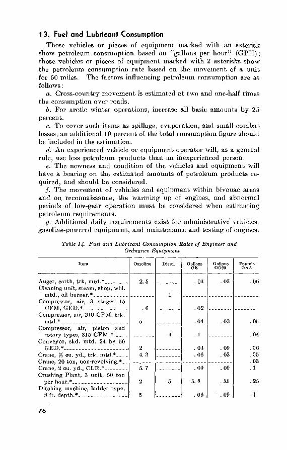
13. Fuel and Lubricant Consumption Those vehicles or pieces of equipment marked with an asterisk
show petroleum consumption based on “gallons per hour” (GrPH) ; those vehicles or pieces of equipment marked with 2 asterisks show the petroleum consumption rate based on the movement of a unit for 50 miles. The factors influencing petroleum consumption are as follows :
a. Cross-country movement is estimated at two and one-half times the consumption over roads.
b. For arctic winter operations, increase all basic amounts by 25 percent.
c. To cover such items as spillage, evaporation, and small combat losses, an additional 10 percent of the total consumption figure should be included in the estimation.
d. An experienced vehicle or equipment operator will, as a general rule, use less petroleum products than an inexperienced person.
e. The newness and condition of the vehicles and equipment will have a bearing on the estimated amounts of petroleum products re- quired, and should be considered.
/. The movement of vehicles and equipment within bivouac areas and on reconnaissance, the warming up of engines, and abnormal periods of low-gear operation must be considered when estimating petroleum requirements.
g. Additional daily requirements exist for administrative vehicles, gasoline-powered equipment, and maintenance and testing of engines.
Table 14- Fuel and Lubricant Consumption Rates of Engineer and Ordnance Equipment
Item Gasoline
Auger, earth, trk, mtd.* Cleaning unit, steam, shop, whl.
mtd., oil burner.* Compressor, air, 3 stages 15
CFM, GED.* Compressor, air, 210 CFM, trk.
mtd.* Compressor, air, piston and
rotary types, 315 CFM.* Conveyor, skd. mtd. 24 by 50
2. 5
. 6
5
GED.* Crane, % cu. yd., trk. mtd.* Crane, 20 ton, non-revolving.*. _ Crane, 2 cu. yd., CLR.* Crushing Plant, 3 unit, 50 ton
per hour.* Ditching machine, ladder type,
8 ft. depth.*
2 4. 3
5. 7
2
5
Diesel
i
4
5
Gallons OE
. 03
. 02
. 04
. 1
. 04
. 06
. 09
5. 8
. 06
Gallons 0090
. 03
. 03
. 09
. 03
. 09
. 35
. 09
Pounds GAA
. 06
. 05
. 04
.06
. 05
. 03
. 1
. 25
. 1
76

Table H. Fuel and Lubricant Consumption Rales of Engineer and Ordnance Equipment—Continued
Item Gasoline Diesel Gallons OE
Gallons GODO
Pounds OAA
Distributor, bit., trk. mtd. 800 gnl. cap.*
Distributor, water, trk. mtd., 1000 gal.*
Dolly, 4 wheel for 20 ton semi.*_ Electric lighting equipment, set
#4, 5 KW.* Electric lighting equipment, sot
#5, trk. mtd., 15 KW.* Flood light equipment, set #2,
GED.* Grader, road motorized.* Heater, asphalt, tlr. mtd.* Kettle, asphalt, tlr. mtd., 165
gal.* Loader bucket.* Lubricator, tlr. mtd.* Mixer, concrete, tlr. mtd. 16 cu.
ft.* Mixer, rotary-tiller.* Power unit, #162.* Pump, asphalt, tlr. mtd.* Pump, diaphragm, push cart
mtd.* Pump, centrifugal for gas, 3” by
240 GPM @ 60 ft. head.* Quarry set #1, wagon drills.* Roller, road, 5-8 ton.* Roller, road, 3 wheel, 10 ton.*-. Roller, road, towed type, 50
ton.* Roller, road, towed type, 13
wheel.* Roller, road, towed type, sheep-
foot.* Rooter, 3 tooth, H-3.* Scraper, towed type, 8 cu. yd.*.. Scraper, towed type, 12 cu.
yd.* Scraper, towed type, 18 cu.
yd.* Shop equipment, motorized
GP.* Shop equipment, motorized,
heavy machine.* Spreader, aggregate, towed
type.* Sweeper, 2-way, sweeping.* Tool set #3, emergency shop,
1^ KW gen., GED.*
4. 1
4. 1
3. 5
3
3. 5
. 6
. 6 8. 75 1
2 2. 3
. 6 2
. 6
. 8
4 2. 5
2 5
3. 8
2 2. 5
1. 6
1. 6
04
04
.05
. 03
. 06
. 02
. 02
. 04
. 02
. 03
. 09 , 01 . 03
, 02
, 03 . 03 . 05 03
. 02
02
03 03
02
. 03
. 03
. 03
. 03
. 03
. 06
. 02
. 03
. 03
. 03
. 05
. 05
. 03
.06 02
03 06 01
03 06
03
. 03
. 03
. 03
. 03
. 03
, 03 . 03 . 04
, 05
, 06
. 05
05
03
77

Table 14- Fuel and Lubricant Consumption Rales of Engineer and Ordnance Equipment—Continued
Item
Tractor, saw, wheelbarrow type.*
Tractor, wheel type, 3,000 to 3,700 DBF.*
Tractor, wheel type, 20,025 to 27,000 DBF.*
Tractor, D-6.* Tractor, D-7.* Tractor, D-8.* Truck, utility, % ton, 4 by 4.**__ Truck, % ton, 4 by 4.** Truck, IYï ton, 4 by 4.** Truck, 1J4 ton, 6 by 6.** Truck, 2}{ ton, 6 by 6.** Truck, 4 ton, 6 by 6.** Truck, wrecker, 4 ton, 6 by 6.**_ Truck, dump, 5 ton.** Truck, 5 ton, 6 by 6.** Truck, med. wrecker, 5 ton,
6 by 6.** Truck, prime mover, 6 ton,
6 by 6.** Truck, hvy wrecker, 6 ton, 6 by
6.** Truck, prime mover, 7}^ ton,
6 by 6.** Truck, crane.** Truck, tractor, 5-6 ton (10-ton
semitrailer).** Truck, tractor, 12 ton.** Water, purification set #3,
GED.**
Gasoline Diesel
3 6 7 7 9
17 17 20 17
19
25
20
20 34
17 50
6. 3 6 6 6
Gallons OE
. 02
. 03
. 2
. 1
. 1
. 1
. 1
. 1
. 2
. 2
. 2
. 3
. 3 1. 3
. 4
. 4
. 5
. 5
. 5
. 4
. 4
. 9
Gallon GO90
. 02
. 03
06 07 07 07
. 3
. 6
Pounds GAA
. 04
. 05
. 04
. 05
. 05
. 05
. 2
. 3
. 5
. 4
. 6 1 1 1. 3
. 9
. 5
. 9
. 9
. 9 . 7
. 6 1. 3
14. Identification of Engineer Equipment Repair Parts Manufacturers frequently stamp individual parts with a part num-
ber which furnishes a hint as to the part’s identity. However, .many parts bear stamped or casting numbers which are not the manu- facturer’s part number, and numerous manufacturers have parts which bear no number. Some manufacturers who use a parts-num- bering system and a summary of their systems are shown in table 15.
a. The supply manuals in the 5-3-series contain identification and cross reference information for all Engineer repair parts which arc assigned Federal Stock Numbers and are stocked in the CONUS Depot system.
b. Supply Manuals 5-3-1-1 through 5-3-1-6 contain the manu- facturer’s part and/or drawing number, the item noun, corresponding Federal Stock Number and former Engineer Stock number for the
78

item. The manufacturer’s part and/or drawing numbers, which arc arranged in alphabetical-numerical sequence in this scries of manuals, will sometimes correspond with the manufacturer’s stamped or casting number found on the part. This information would provide some assistance in the identification of Engineer repair parts where only the stamped or casting number is available.
Table 15. Engineer Equipment Repair Parts Identification
Manufacturer Parts-numbering system
Allis-Chalmers Manufacturing Company (power units).
AI lis-Chai mers Manufacturing Company (tractors).
Caterpillar Tractor Company
Chrysler Corporation International Harvester Company.
R. G. LeTourneau, Incorporated..
P and H Company
Wallace-Tiernan, Incorporated
Wisconsin Company
Six-digit numbers. Parts manufactured on subcontracts bear a 2- to 4-digit number, often that of the contractor, prefixed by the letter U.
Five- to 7-digit numbers. Attachments have from 3- to 6-digit numbers prefixed or suffixed by various single letters.
One digit followed by a single letter followed by a 4-digit number. Some few parts bear old numbers which are simply 5- or 6-digit numbers, or 4-digit numbers prefixed by the letters L or S.
Four- to 7-digit numbers. Four- or 5-digit numbers suffixed by the
letters, D, DA, DAX, DX, DXA, or H. One- to 4-digit numbers prefixed by the
letters C, D, E, F, H, L, or R. Two-digit number followed by the letters H,
K, N, P, or T, followed by a 3- or 4-digit number.
One- to 4-digit numbers prefixed by the letters P, U, R, CPC, CPU, CPW, CU, CUR, CUW, CUX, or WPP.
One- to 4-digit numbers prefixed by a 2- letter symbqb
Section III. USA F AIRCRAFT AND AIRFIELD DATA
1 5. USAF Airfield and Aircraft Characteristics The major types of theatre airfields, the critical types of USAF air-
craft for each, and certain characteristics of these aircraft.are given in table 16.
16. Airfield Requirements a. Allowances used to determine the overall requirements for the
logistical planning of airbase and airfield structures are given in table 17.
b. Labor and tonnage requirements for airfield construction and reconstruction are given in table 18.
c. Typical airfield construction quantities are given in table 19.
79 533506°—60 6

oo O
Table 16. USAF Airfield and Aircraft Characteristics
Airfield type
Forward cargo (short-time use).
Forward cargo (extended use).
Forward tactical.
Medium bomber.._
Heavy bomber..
Aircraft type
Medium cargo.
Heavy cargo. _
Critical type USAF
designation
C-119C
C-124C
Fighter.
Medium bombers.
Heavy bomber.
F-101A
B-47E
B-52 B & D
Gross weight (pounds)
73,200.
185,000.
(')
200,000.
Maximum wheel load (pounds)
Maximum tire pressure (psi)
31,500.
86,000.
(')
Over 400,000..
Rear assembly load 103,200.
69.6.
78.0.
(0
Rear assembly load over 200,000.
Front 181.2; Rear 189.5.
Overall dimensions (feet)
Length
86. 5
130. 0
67. 5
107. 1
(')
Wing span .
109. 3
174. 1
39. 8
116. 0
156. 5 185. 0
Height
26. 5
48. 3
18. 0
Tread
Main gear
32. 3
37. 3
(0
28.0 NA
(‘) NA
Outer gear
NA
NA
NA
Takeoff ground
run (feet) @ sea
level and 59° F.
2, 640
5, 520
(0
44. 3 8, 050
148. 4 0)
i Classified.

Table 17. Airbase and Airfield Allowances
Construction standard
Facility
Space Allowances: Quarters Kitchen Dining facilities: Family style Cafeteria style Unit administration Unit supply - Unit recreation and welfare Unit medical Sanitary Installations: Toilet seat and
urinals
Showers
Lavatory
Scrub deck or laundry Water Allowances: Kitchens Showers and lavatories Latrines _ Lighting Allowances: Quarters Kitchens Dining facilities
Unit of measure
Square Square Square Square Square Square Square Square
feet per feet per feet per feet per feet per feet per feet per feet per
person _ person, person. person. person, person. person, person.
Persons per fixture Square feet per seat and urinal1
Persons per head Square feet per head Persons per fixture Square feet per fixture Square feet per person Gallons per person per day Gallons per person per day Gallons per person per day Watts per square foot Watts per square foot Watts per square foot
Field >
Ofliccrs Airmen
80
M «
«
(4)
(*)
M (4)
« (4) «
(4)
40 (4) (4)
(4)
(4)
(4)
(4)
(4)
(4)
(4)
(4) (4)
(4)
(4)
Intermediate >
Officers Airmen
80. 0 6. 0
12. 0 6. 0 2. 0 2. 0 6. 0 1. 0
10. 0 25. 0 10. 0 50. 0
5. 0 15. 0
2. 0 5. 0
20. 0 0. 0 0. 4 0. 6 0. 4
40. 0 4. 0 8. 0 4. 0 2. 0 2. 0 4. 0 1. 0
6 20. 0 25. 0 20. 0 50. 0 10. 0 15. 0
2. 0 5. 0
20. 0 0. 0
0. 4 0. 6 0. 4
Temporary •
Officers Airmen
80. 0 7. 5
15. 0 7. 5 3. 0 3. 0 9. 0 1. 0
10. 0 25. 0 10. 0 50. 0 5.0
15. 0 2. 0 5. 0
20. 0 10. 0
0. 4 0. 6 0. 4
40. 0 5. 0
10. 0 5. 0 3. 0 3. 0 6. 0 1. 0
5 20. 0 25. 0 20. 0 50. 0 10. 0 15. 0
2. 0 5. 0
20. 0 10. 0 0. 4 0. 6 0. 4
00 See footnotes at end of table.

00 ho
Table 17. Airbase and Airfield Allowances—Continued
Facility
Unit administration Unit supply Unit recreation and welfäre- Showers Lavatories Toilet seats and urinals
Unit of measure
square foot- square foot- square foot, square foot.
Watts per Watts per Watts per Watts per Watts per square foot Watts per • sonare foot
Construction standard
Field 1 2 *
Officers
« (4)
(4)
(4)
(4)
(4)
Airmen
(4)
(4)
(4)
(4)
(4)
(4)
Intermediate >
Officers
1. 0 0. 2 1. 2 0. 3 1. 6 0. 2
Airmen
1. 0 0. 2 1. 2 0. 3 1. 6 0. 2
Temporary >
Officers
1. 0 0. 2 1. 2 0. 3 1. 6 0. 2
Airmen
1. 0 0. 2 1. 2 0. 3 1. 6 0. 2
1 This is equivalent to OCE Construction Standard No. 2. 2 This is equivalent to OCE Construction Standard No. 4. > This is equivalent to OCE Construction Standard No. 6.
< Not applicable. » Reduce to 15 persons per fixture for WAF. « For trough urinals, 2 feet of trough equals one urinal.

Table 18. Airfield Labor and Tonnage Requirements
New Construction 1
Airfield typo and critical aircraft
Forward cargo, medium C-119C (one wing)
Forward cargo, heavy C-124C (one wing)
Forward tactical F-101A (one wing)
Medium bomber B-47E (one wing)
Heavy bomber B-52 B and D (one wing)
Engineer battalion-months 2
Stage I
2. 5
6. 0
11. 0
12. 0
Stage II
11. 0
9. 0
16. 0
18. 0
Stage III
15. 0
13. 0
27. 0
30. 0
Construction supplies 3
Measure- ment tons
1, 200
3, 000
9, 000
35, 000
50, 000
Short tons
1, 200
3, 000
9, 000
24, 000
35, 0Ö0
1 For rehabilitation of a site where an airfield exists or has existed use 75 percent of the above factors, a Battalion-months are computed on the basis of 110,000 effective man-hours per month for one engineer
construction battalion TOE 5-115D, full strength. 3 This figure will fluctuate due to site selection and construction material selection.
83

00 A
Table 19. Typical Airfield Construction Quantities
Runway (paved 10,000 ft. by 300 ft
Runway (paved 6,500 ft. by 150 ft)
Main taxiway Apron access taxi way Hardstand area warmup apron,
taxi way Circulation taxiways Main transport apron Service apron Warmup apron Drum-fill area Transport hardstands — Roads
Total 1
Surfaced area (square
yards)
333, 300
108, 300 41, 500 17, 700
14, 500 3, 900
72, 200 17, 800
4, 400 9, 600 5, 800
68, 000
Graded area (square yards)
363, 700
769, 250
250, 000 64, 200 28, 400
23, 200 6, 200
82, 300 21, 200
5, 100 10, 000 10, 000
111, 500
Base course (cubic yards)
612, 100
100, 000
32, 500 12, 400
5, 300
4, 400 1, 200
21, 700 5, 300 1,300 1, 600 1, 700
11, 300
98, 700
Asphalt (gallons)
249, 800
81, 200 24, 900 10, 600
8, 700 2, 300
43, 300 10, 700
2, 600
Chips (cubic yards)
3, 500
187, 800
3, 320
1, 080 420 180
150 40
720 180 40
60
Stripping (cubic yards)
92, 300
30, 000 7, 000 6, 000
Excavation (cubic yards)
2, 870
1, 000 17, 000
7, 000 2, 000 3, 000
4, 000
77, 000
307, 700
100, 000 35, 000 30, 000
Fill (cubic yards)
246, 200
80, 000 29, 000 25, 000
2, 000 20, 000 10, 000
5, 000 6, 000
25, 000
233, 000
2, 000 17, 000
8, 000 4, 000 4, 000
Rock (cubic yards)
4, 350
1, 350
Culverts (feet)
(diam- eter
inches)
200-36 300-36
20, 000
189, 000 1, 350
210-36
200-18
710-36 200-18
i With 6,500-ft. by 150-ft. runway.
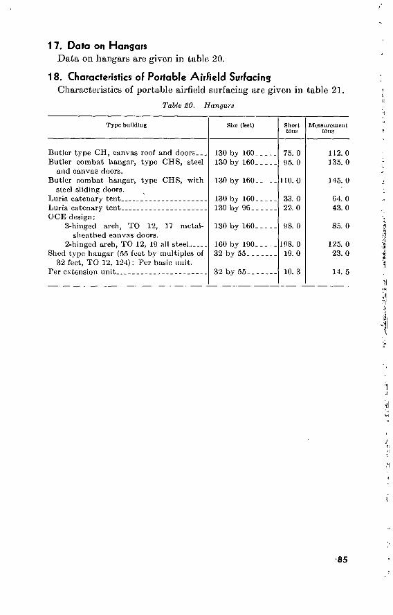
1 7. Data on Hangars Data on hangars are given in table 20.
18. Characteristics of Portable Airfield Surfacing Characteristics of portable airfield surfacing are given in table 21.
Table SO. Hangars
Type building
Butler type CH, canvas root and doors Butler combat hangar, type CHS, steel
and canvas doors. Butler combat hangar, type CHS, with
steel sliding doors. Luria catenary tent Luria catenary tent OCE design :
3-hinged arch, TO 12, 17 metal- sheathed canvas doors.
2-hinged arch, TO 12, 19 all steel Shed type hangar (55 feet by multiples of
32 feet, TO 12, 124): Per basic unit. Per extension unit
Size (feet)
130 by 160_ 130 by 160-
130 by 160-
130 by 160- 130 by 96-.
130 by 160-
160 by 190- 32 by 55-..
32 by 55_
Short tons
75. 0 95. 0
110. 0
33. 0 22. 0
98. 0
198. 0 19. 0
10. 3
Measurement tons
112. 0 135. 0
145. 0
64. 0 43. 0
85. 0
125. 0 23. 0
14. 5
1 Kl j|
•]
^1
fi\
Vi *1
<1
85

■- ■- ' f
00 O'
Table 21. Characlerislics of Portable Airfield Surfacing
Type
Unit weight and dimensions: Weight (pounds per square feet) - - Length Width Depth Placing area—1 panel (square feet)
Bundles: Number of units Square feet placing in 1 bundle Gross weight per bundle (pounds) Bundle dimensions, width, length
height
PSP (10 ga)
5.1... lO'O".
Volume—1 bundle (cubic feet) Requirements for 5,000 by 150' runway:
Quantity (bundles or rolls) Weight (tons) Cargo space (cubic feet) Ship tons (40 cubic feet equals 1
ship ton) Cargo density (pounds per cubic
feet gross weight) Area covered per cubic feet cargo
space Average laying speed (square feet per
man-hour)
12.5.
30 planks *_ 375 1,928
V02" by 10'0” by 1'2".
16.0
2,000.. 1,928. . 32,084.
802.10.
120.18.
23.376.
125--..
M-6 (10 ga)
5.4... lO'O". 1'3"-.
12.5-.
30 planks 375 2,055
1'4H" by 10'- 1%" by 1'2''.
16.3
2,000. _
2,055._ 32,552.
813.80.
126.26.
23.040.
60-75 2
M-8 (10 ga)
7.3 11'9%". 1'7H".. i 7» 19.2.
14 planks. 268.8 1,960
l'10/2''by 12'1" by 1'0'\
22.7
2.790.. 2.734.. 63,333.
I, 583.25.
86.34.--
II. 8415-
150 2
PAP (?W')
2.54. lO'O" 1'3". 1"__.
12.5.
M-9 (Me")
30 planks. 375 975
1'5" by lO'O" by 1'3”.
17.7
2,000..
975--.. 35,418.
885.45.
55.06.-
21.176-
150--..
3.7. 11'9K". 1'10>4". 1^".
21.8.
14 planks. 305.2. 1,120.
2'3" by 12'1" by 1'3J4".
35.6.
2,450. 1,376. 87,505.
2,188.
31.46.
8,573.
175.2
. Breaks denvn into 0 subbundles of 5 each. 1 subbundle contains 2 half panels and 4 full panels. Each bundle of M-G contains end connectors. Each bundle of PSP contains clips.
! Estimated—based on limited information.

Section IV. U.S. ARMY AIRCRAFT AND AIRFIELD DATA
19. Army Aircraft Characteristics
The major types of Army aircraft and certain of their characteristics are given in table 22.
20. Army Airfield Design Criteria
Design criteria for Army airfields arc given in table 23. For flight- way and flightstrip nomenclature, see figures 1 and 2.
u z < ac <
Z O Nl
OVERRUN
CLEARED AREA
SHOULDER
RUNWÀY
SHOULDER-
CLEARED AREA
2
'A
Figure 1. Flightstrip nomenclature.
CLEAR ZONE A/,PR
°ACH 4 y
GLIDE ANGLE
Figure 2. Flightway nomenclature.
21. Army Heliport Design Criteria
Army heliport design criteria are given in table 24.
87
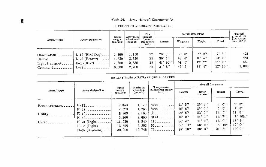
00 00
Table 2%. Army Aircraft Characteristics
FIXED-WING AIRCRAFT (AIRPLANES)
Aircraft type
Observation Utility Light transport. Command
Aircraft type
Reconnaissance.
Utility
Cargo
Army designation
L-19 (Bird Dog). L-20 (Beaver)... U-l (Otter) L-23
Gross weight
(pounds)
2, 400 4, 820 7, 600 6, 000
Maximum wheel load (pounds)
1, 150 2, 350 2, 850 2, 700
Tire pressure (pounds
per square Inch)
22 25 28 35
Overall dimensions
Length
22' 0”
30' 4" 41' 10" 31' 6"
Wingspan
36' 0” 48' 0" 58' 0” 45' 5''
Height
9' 2" 10' 5" 12' 7' 11' 4'
Tread
7' 5" 10' 2"
11' 2"
12' 10'
ROTARY-WING AIRCRAFT (HELICOPTERS)
Army designation
H-13 H-23 H-19 H-40 H-21 (Light) H-34 (Light). .. H-37 (Medium).
Gross weight
(pounds)
2, 350 2, 570 8, 100 5, 200
11, 520 13, 300 30, 900
Maximum wheel load (pounds)
1, 170 1,285 2, 700 2, 600 3, 840 5, 892
13, 745
Tire pressure (pounds per square
Inch)
Skid. Skid. 35.. . Skid. 115.. 55.. . 75.. .
Overall dimensions
Length
41' 5” 40' 6” 62' 5'' 48' 9" 86' 4" 65' 10" 82' 10"
Rotor diameter
35' 2" 35' 0" 53' 0" 44' 0" 44' 0" 56' 0" 68' 0"
Height
9' 6" 9' 9"
14'
14' 16' 15'
21'
Takeoff ground run (TGR): sea level, 59° F.
5" 7" 0"
10"
6"
421 481 550
1, 000
Tread
7' 6" 7' 6"
11' 0"
7' IO/4" 13' 4" 12' 0"
19' 9"

Table 23. Army Airfield Design Criteria
oo »0
Pioneer 1 Hasty Deliberate
RUNWAY
1
2
3 4 5
6 7
8
9 10 a 12
Length (to nearest 100 ft.); corrected takeoff ground run multiplied by (safety factor).
Width (minimum)
Shoulder width (minimum) Lateral clearance (width) of flightstrip Runway surfacing
Longitudinal grade (maximum) Maximum rate of change in grade per 100 ft.
on vertical curves. Minimum sight distance across vertical curves
(height of eye 5', to a point 5' above run- way surface).
Minimum distance PI to PI on vertical curves. Transverse slope (minimum) Transverse slope (maximum) Transverse shoulder slope (minimum)
1.10.
50 ft. sod or unpaved or 25 ft. shoulder-to- shoulder gravel or better road; open held.
0 ft 150 ft In-place sod or com-
pacted base course. 10 percent 1.0 percent
y> runway length
200 ft Natural surface 5 percent NA
13 Transverse shoulder slope (maximum) 14 Parallel runways (minimum spacing, center
to center). 15 Cleared areas, maximum slope
See footnote at end of table
NA 200 ft
Unlimited
1.50-
50 ft.
10 ft 200 ft Portable
5 percent 0.5 percent
500 ft. plus % runway length.
600 ft 1.5 percent 3.0 percent J>2 percent greater than
runway transverse slope.
5.0 percent 300 ft
10 percent
1.75.
75 ft.
10 ft. 300 ft. Rigid or flexible pave-
ment. 3 percent. 0.333 percent.
500 ft. plus Yi runway length.
800 ft. 1.5 percent. 3.0 percent. Yi percent greater than
runway transverse slope.
5.0 percent. 300 ft.
10 percent.

-o o Table 23. Army Airfield Design Criteria—Continued
16
17 18 19 20 21 22
.23 24
25 26
27
28 29
Pioneer ' Hasty Deliberate
TAXI WAYS
Width (to nearest 10 ft.) Landing gear tread multiplied by — but not
' less than—. Shoulder width (minimum) Lateral clearance, taxiway width plus — Longitudinal grade (maximum) Transverse slope (minimum) Transverse slope (maximum) Transverse shoulder slope (minimum)
NA. NA.
NA. NA. NA. NA. NA. NA.
Transverse shoulder slope (maximum) NA Taxiway horizontal curves except at inter- NA
sections, minimum radius.
20 ft 1.5
5 ft Airplane wingspan 6 percent 1.5 percent 4 percent 0.5 percent greater than
taxiway transverse. 5 percent 75 ft
20 ft. 1.75
5 ft. Airplane wingspan. 6 percent. 1.5 percent. 3.0 percent. 0.5 percent greater than
taxiway transverse. 5 percent. 100 ft.
HARDSTANDS AND APRONS
Fillets of junction, minimum radius Diameter (minimum) or minimum dimension
of square or rectangle. Width of hardstand where camouflage is re-
quired if manpower is used to move aircraft from taxiway.
Shoulder width Minimum spacing, hardstands (center to cen-
ter).
NA. NA.
NA.
NA. NA.
0 ft 30 ft
Airplane tread plus 5 ft.
0 ft 100 ft
10 ft. 30 ft.
Airplane tread plus 5 ft,
5 ft. 100 ft.
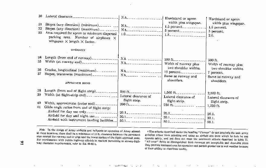
30
31 32 33
34 35
36 37
38 39
40 41
Lateral clearance
Slopes (any direction) (minimum) Slopes (any direction) (maximum) Area required for apron or minimum dispersal
parking area. Number of airplanes X wingspan X length X factor.
OVERRUN
Length (from end of runway) Width (at runway end)
Grades, longitudinal (maximum) Slopes, transverse (maximum)
APPROACH ZONE
Length (from end of flight strip) Width (at flight-strip end)
Width, approximate (outer end) Glide angle ratios from end of flight strip:
Airfield for day use only Airfield for day and night use Airfield with instrument landing facilities..
NA.
NA. NA. LO-
NA NA.
NA. NA.
500 ft Lateral clearance of
flight strip. 200 ft
20.1 30.1 50.1
Hardstand or apron width plus .wingspan.
1.5 percent 5 percent 1.5
300 ft Width of runway plus
two shoulder widths. 10 percent Same as runway and
shoulders.
1,500 ft Lateral clearance of
flight strip. 750 ft
20.1 30.1 50.1
Hardstand or apron width plus wingspan.
1.5 percent. 5 percent. 2.0.
500 ft. Width of runway plus
two shoulder widths. 7 percent. Same as runway and
shoulders.
2,500 ft. Lateral clearance of
flight strip. 1,250 ft.
20.1.
30.1. 50.1.
Note. In the design of Army airfields and heliports or operation of Army aircraft at these locations, there shall be a minimum of J5 ft. clearance between the pavement edge nearest the runway end or edge and the lower surface of the flight approach zone. For coordination with public highway officials in matters pertaining to airway-high- way clearance requirements, refer to SR 55-80-1.
1 The criteria described under the head tag “ Pioneer” do not preclude the unit army aviation officer from selecting and using an airfield site from which he feels he can operate safely, and yet docs not meet the minimum criteria described in tabic II. “All over” fields as distinguished from runways are acceptable and desirable since they provide increased area for operation and permit greater use in wet weather because of their ability to distribute traffic.

RUNWAYS (LANDING AREA AND TAKEOFF AREA)
1 Length, recommended minimum (dependent on type of helicopter and site conditions).
2 Width 3 Landing surfaces
4 Lateral clearance (min.) 5 Grade, in any direction (max.) 6 Transverse slope (min.) 7 Shoulder width 8 Overrun width
9 Overrun length 10 Shoulder and overrun, grade (max.) 11 Parallel or adjacent runways (min.) center-to-
center spacing. 12 Cleared areas, max. slope
TAXI WAYS
13 Width 14 Longitudinal grade (max.) 15 Transverse slope (max.) 16 Shoulder width 17 Shoulder slope (max.) 18 Lateral clearance
Zlt. Army Heliport Design Criteria
Hasty Deliberate Pioneer 1
100 feet
25 feet In-place sod or com-
pacted base course. 100 feet 8.0 perent 0 percent 0 feet None
None None 200 feet
+ 10 percent
None. None. None NA-- None None
300 feet
25 feet In-place sod or dust-
free portable surface. 150 feet 4.0 percent 1.5 percent 10 feet Same as runway width
plus two shoulders. 50 feet None 200 feet
+ 10 percent
20 feet 3.0 percent. 3.0 percent. 35 feet 3.5 percent 90 feet
450 feet.
40 feet. Flexible or rigid pave-
ment. 250 feet. 3.0 percent. 1.5 percent. 10 feet. Same as runway width
plus two shoulders. 100 feet. 3.5 percent. 300 feet.
+10 percent.
30 feet. 2.0 percent. 3.0 percent. 35 feet. 3.5 percent. 100 feet.

HARDSTANDS AND APRONS
19 Diameter, circular hardstands, or minimum dimension square or rectangular hardstands.
20 Slope, any direction (max.) 21 Slope, any direction (min.) 22 Shoulder width 23 Shoulder slope (max.) 24 Shoulder slope (min.)
None
None None NA__ None None
25 Lateral clearance 26 Spacing, hardstands, center-to-center (min.).. 27 Apron or minimum parking area: Number of
helicoptersXbladespanXoverall length X factor.
None None 1.0..
30 feet 40 feet.
3.0 percent 1.0 percent 30 feet 3.5 percent
percent greater than hardstand slope.
90 feet 110 feet 1.5
2.0 percent. 0.5 percent. 30 feet. 3.5 percent. Ÿï percent greater than
hardstand slope. 100 feet. 125 feet. 2.0.

Section V. RAILROAD DATA 22. General
Responsibilities regarding railroads are covered in AR 55-650. Railroad bridges are covered in the TM 5-370-series; railroad surveys in the TM 5-235-series. Details of railroad engineering practice are given in various handbooks in engineer unit libraries.' Railway gages and mileages of the world are given in paragraph 28.
23. Rail Shipments of Engineer Equipment а. General. Large items of engineer motorized and other heavy
construction equipment, when shipped by rail assembled or partially assembled and uncrated, are normally loaded lengthwise onto flatcars or drop-end gondolas. For dimensions of such equipment, see para- graphs 10 and 11. For dimensions of standard American railway cars, see FM 55-15.
б. Number of Items Per Car. To find what fraction of a car the item will occupy, divide the length of the car into the length of the item, plus a small allowance for clearance.
c. Loading on Flatcars. (1) For American mainline railroads and for a flatcar whoso
deck is 3 feet 6 inches above the top of the rail (the most common height), the following are the maximum permissible widths, at various heights, of any item loaded on the car:
At a height,MboD&xdT ßoor~of—i . i i i r. ^ i MaximuruTiermissible width
0 feet (car floor) 10 feet 8 inches 10 feet 3 inches 10 feet 8 inches 10 feet 9 inches 10 feet 0 inches 11 feet 7 inches 7 feet 0 inches
If the car deck is higher than 3 feet 6 inches, figures in the first column must be reduced by the amount in excess of 3 feet 6 inches.
(2) For shipments on branch lines, somewhat lesser maximum heights and widths may have to be used. Clearance dia- grams should be consulted before loading equipment.
d. Loading on Gondolas. Information in c above applies, with the qualification that, from the level of the car deck up to the top of the sides, the maximum permissible width of a loaded item is 6 inches less than the clear inside width of the car. This latter is usually 9 feet 0 inches to 9 feet 5 inches, though in some cases it may be as much as 10 feet 0 inches.
24. Tie Lengths and Embankment Widths Tie lengths and embankment widths for single-track lines of various
gages are shown in figure 3. Embankment widths and other elements of double-track lines, standard gage, are shown in figure 4. The 13-foot track spacing, center to center, is satisfactory for tangent track and is normally the minimum spacing used in multitrack layouts
94

EMBANKMENT WIDTH - TANGENT TRACK
4 OF TANGENTS WIDEN 2 FEET
ON OUTSIDE OF CURVES ! LENGTH OF TIES
4" OR MORE
3" SUBGRADE CROWN
GAGE FT INS
2'-6" OR LESS
LENGTH OF TIES FT INS.
EMBANKMENT WIDTH TANGENT TRACK
FT INS,
(STANDARD) 8'-6" TO 9'*0"
Ç'-ô" TO lO'-O"
Figure S. Cross section, single track.
for both yard and running tracks. In curved track, it is satisfactory for slow traffic only, and the spacing is normally increased to 14 feet or more in running tracks to allow for overhang of equipment, rocking of cars, and inequalities of superelevation.
25. Spacing of Parallel Tracks Body tracks in yards are normally spaced a minimum of 13 feet on
centers, except that the first body track is 15 feet on centers from a running track; and ladder tracks are at least 15 feet on centers from any parallel track. Tracks in pairs for operation of locomotive cranes are spaced at least 18 feet on centers.
26. Clearances Overhead clearances and platform heights are measured from the top
of the rail; side clearances from the centerline of track. Clearances below those specified arc dangerous and require protection by appro- priate warning signs or devices including telltales for overhead clearances between 22 feet and a minimum allowable of 18 feet. Unless local conditions require greater clearances, standard minimum clearances are as follows :
a. Overhead. High-voltage wires, 28 feet; other wires, 27 feet; overhead structures, 22 feet.
b. Side. The following side clearances are the absolute minimum distances. Where any side distance is less than 8 feet 6 inches, it should be posted along the appropriate line and on clearance diagrams.
95 533500°—60 7

31-0"
9-0 (miiïï 9-0 t 13-0
f 2-4 il 2-4 j* ! I I.
j2-44l2-4i‘ 1-0
4 or more j 4 or more
Level ¿Fo aax to .ij FUI
TANGENT ^DOUBLE TRACK
Note : Where soil or frost conditions require, 4* to 6" of cinders, screenings or pit run gravel sub-bollost may be installed.
9-0 13-0 (mini 1
1-0"
1-6 . Cut -T3 uboro
'^^néasi^ 4 or more or more
Level Slope 16:1 Slope 16:1 r-o"
CURVED
DOUBLE TRACK
SCALE: y-i'-o"
Note Gage A'-S^ on curves up to 8°, widened -g- for each 29
over 8* up to a maiimum of 4‘-9*T\
Figure 4- Cross section, double track.
(1) Canopies up to 15 feet 6 inches high, 8 feet 6 inches. (2) Canopies higher than 15 feet 6 inches, 5 feet 6 inches. (3) Buildings, 8 feet 6 inches. (4) Platforms 3 feet 9 inches high, 6 feet 2 inches. (5) Refrigerator platforms 3 feet 2 inches high, 6 feet 2 inches. (6) Refrigerator platforms 4 feet 7 inches high, 8 feet 6 inches. (7) Low platforms 4 inches high, 5 feet 0 inches.
c. Enginehouse Entrances. (1) Overhead, 17 feet 0 inches. (2) Side, 6 feet 6 inches.
d. Bridges and Tunnels. Standard single-track bridge and tunnel clearances are shown in figure 5.
27. Materials for Standard-Gage Track a. Rail. The new and used rail and accessories in the Department
of the Army Supply Manual, SM 5~5, is the 75-pound-per-yard ASCE section, but this when depleted will be replaced by the 85- pound ASCE section in 39-foot lengths.
b. Ties. Ties listed in SM 5-5 are 6 by 8 inches, 8 feet long, for untreated crossties; and 7 by 9 inches, 8 feet long, for creosoted cross- ties, until depleted. Thereafter, the standard width of issue will be 8 feet 6 inches. Ties are produced locally if possible and may be creo- soted if it is necessary to produce them in the United States for ship- ment overseas. Switch ties are listed in the same sizes by plan lengths,
96

22-0"
8-0"-
T“ 6-0"
>4-0-
■ 16-0"
■ 8-0"-
o "CVI
- 8-O-
OF ITRACK
a o iaJl
'Í f
~2'-3"r Fsii BASE OF RAIL
-TOP OF RAIL.
SUBGRADE —
I . O
16-0
14-0"
'2-O'M I
FOR BRIDGES
Figure 5. Standard single-track bridge and tunnel clearances.
FOR TUNNELS, SINGLE TRACK
in sets for number 8 turnouts. The engineering manual for Depart- ment of the Army construction provides minimum sizes of 7 by 9 inches for switch ties and 8 by 8 inches, 10 feet long, for bridge ties. Standard spacing is 19 and 21 ties per 39-foot rail for yard and running tracks, respectively.
c. Tie Plates, Spikes, and Bolts. Steel tie plates, 9 by 6 by % inches in size, are authorized for all track but may be omitted in hasty con- struction except at turnouts and sharp curves. Spikes are issued in the %6- by 5%-inch size, and track bolts in %- by 4-inch and %- by 4%- inch sizes.
d. Ballast. Crushed rock, slag, or gravel, in sizes graded from 3-inch to number 10 sieve, is best. Coarse cinder ballast is satisfactory for yard tracks and sidings and is brought to the tops of the ties to pro- vide good footing for operating personnel. The engineering manual specifies a minimum depth of 8 inches under the ties, but as little as 4 inches can be used in hasty construction. The top of the ballast should clear the bottom of the rails by at least 1 inch. Ballast is produced locally wherever possible.
e Turnouts. The standard turnout is issued unassembled and is complete with low-stand throw and rigid-bolted number 8 frog. Di- mensions and layout information for turnouts and crossovers using various frogs from number 6 to number 18 are given in figure 6.
28. Foreign Railroad Gages and Mileages Standard gage, 4 feet 8% inches (56% inches), is in general use in the
United States. Table 25 gives the latest available information on foreign gages.
97
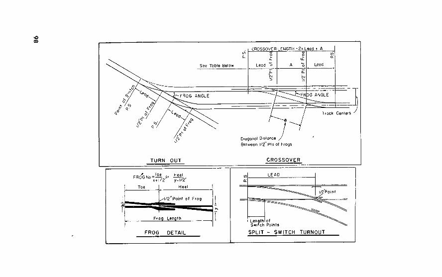
o 00
CROSSOVER-LENGTH =2X Lead + A
Lead Lead See Table Below
FR DG ANGLE FROG ANGLE
Track Centers
Diagonal Distance Between 1/2" Pis of Frogs
TURN OUT CROSSOVER
FROWM2..or ^
Toe Heel
^1/2' Point of Frog
Frog Length
FROG DETAIL
LEAD
l/2Point
Len Switch Points
SPLIT - SWITCH TURNOUT

DIMENSIONS OF FROGS, SWITCHES, TURNOUTS AND CROSSOVERS
FROGS
O Z <
o o
o z
o o
SWITCHES
n O O Q.
X X
o ¥ _< (/)
s o £ o o
S i 2 z y ^
io * O </>
Û __
a O < ■
LEAD CURVE
3 a <
si
u u
o UJ a
TURNOUTS AND CROSSOVERS
DISTANCE IN FEET
BETWEEN CENTER LINES
OF TRACKS—GAGE—4'-8 1/2"
13'-0"
B
14'-0"
B
*6^
B
9°3r38''
8o10'16''
7°09/10"
6021'35'
5043'29"
4°46'19"
4°05'27''
3034'47"
3o10'56"
lO'-O"
12'-0"
13'-0"
16'-0''
16'-6"
20'-4"
23/-7"
26'-0"
29'-3"
11'-0"
16'-6"
16'-6"
16'-6"
16'-6"
22'-0"
S2'-0"
30'-0"
30'-0"
47'
62'
68
72'
78
96'
107'
131'
140'
6"
1"
0"
3 1/2"
9"
8"
0 3/4"
4"
11 1/2'
258.57
365.59
487.28
615.12
779.39
1104.63
1581.20
2007.12
2578.79
22°17'
!5°43'
11°46'
9° 19'
7°21'
5°11'
3° 37'
2°5r
2°13'
20'-5 1/2"
24'-0 3/8"
27'-7 1/8"
31'-1 5/8"
34'-8 1/8"
41'-8 3/4"
48'-9 1/4"
55'-9 5/8"
62'-9 7/8"
21'-6 1/2"
24'-11 5/8"
-4 7/8"
-10 3/8"
-3 7/8"
-3 1/4"
-2 13/16"
-2 1/2"
-2 3/16"
28'-.
31'
35'
42'-:
49'-:
56'-:
63'-:
26'-5"
30'-11 15/16"
35'-6 3/4"
-1 5/16"
7 13/16"
-8 1/2"
-9 1/16"
-9 7/16"
■9 11/16"
40'
44
53'
62'
7V
80'
-7"
0 1/16"
5 1/4"
10 11/16'
4 3/16"
3 1/2"
3 1/16"
-2 11/16"
2 3/8"
11
11
11
11
-11
11
11
11
11
1/2"
9/16"
5/8"
11/16"
11/16"
3/4"
13/16"
13/16"
13/16"
0 1/2"
-0 7/16"
-0 3/8"
-0 5/16"
-0 5/16"
-0 1/4"
-0 1/4"
-0 3/16"
-0 3/16"
-¡¡■/COLUMNS A & B UNDER Q GIVE THE AMOUNTS TO ADD TO TABULAR FIGURES FOR
EVERY ONE (1) FOOT INCREASE IN DISTANCE BETWEEN TRACKS
Figure 6. Frogs and switches in turnouts and crossovers.

Table 25. Foreign Railroad Gages and Mileages
Country
Europe: Albania
Austria
Belgium
Bulgaria
Czechoslovakia
Denmark
Finland
France
Germany: West
East
Great Britain _ _
Greece
FI ungary
Eire
Italy
Luxembourg
Netherlands. Norway
Track gage
Indies Meters
Total length of railroads
Miles Kilometers
56)4 24 56'A ■30% 29 56/4 39% 56%, 30 23% 60 56/;
39% 29 56'< 39/g 60 56% 56 39/6
56% 39% 29% •56%
39% 29% 56% 36 56% 39% 23% 56% 29% 63 36 56% 42% 39% 37% 29% 56% 39% 56% 56% 42 39% 30
1. 434 . 609
1. 434 1. 000
. 760 1. 434 1. 000 1. 434
. 762
. 600 1. 524 1. 434 1. 000
. 750 1. 434 1. 000 1. 524 1. 434 1. 434 1. 000
I. 434 1. 000
. 760 1. 434 1. 000
. 750 1. 434
. 914 1. 434 1. 000
. 600 1. 434
. 760 1. 600
. 914 1. 434 1. 067 I. 000
. 950
. 750 1. 434 1. 000 1. 434 1. 434 1. 067 1. 000
. 762
79 19
3, 440 10
305 3, 168 2, 513 2, 420
186 95
5 8, 000
105
2, 885 42
3, 022 3
25, 151 549
18, 811
144
8, 450
650
19, 276 32
900
660
4, 950 210
1, 892 136
11, 424
2, 090
249 89
1, 979 2, 691
112
126 30
5, 507 16
488 5, 068 4, 020 3, 872
297 152
8 12, 800
168
4, 616 67
4, 835 5
40, 241 878
30, 097
230
13, 520
1, 040
30, 841 51
1, 440
1, 056
7, 920 336
3, 027 217
18, 278
3, 344
398 142
3, 166 4, 305
179
100

Table 25. Foreign Railroad Gages and Mileages—Continued
Country
Poland
Portugal.
Ru mania
Saar. Spain
Sweden
Switzerland
Yugoslavia.
Asia: Burma Ceylon
China.
Hong Kong India
GO 56M 39% 30 29% 23% 66 39% 60 56% 39% 29% 56% 66 56% 48 39% 36 29% 23% 60 56% 42
35% r, 30 56% 39% 31% 29% 56% 39% 30 23%
39% 60 30 56% 39%
Other 56% 66 39% 30 24
1. 524 1. 434 1. 000
. 762 . 750 . 600
1. 524 1. 000 1. 524 1. 524 1. 000 1
. 750 J 1. 434 1. 677 1. 434 1. 219
. J *±
. 750
. 600 1. 524 1. 434 1. 067
. 891
. 762 1. 434 1. 000
. 800
. 750 1. 434 1. 000
. 762
. 600
1. 000 1. 667
. 762 1. 434 1. 000 \ Other I 1. 434 1. 677 1. 000
. 762
. 609
30 13, 500
350 151 608 768
1, 759 477
50 5, 900
430
343 8, 048
2, 997
1
8, 158 318
1, 375
2, 223 735 30
9 5, 619
104 1, 639
201
1, 787 888
87 19, 000
3, 040
22 15, 696 14, 969
2, 929 427
48 21, 600
560 241 972
1, 228 2, 814
763 80
9, 440
688
548 12, 876
4, 795
13, 052 508
2, 200
3, 556 1, 176
48 14
8, 990 166
2, 622 321
2, 859 1, 420
139 30, 400
4, 868
35 25, 113 23, 950
4. 686 683
Track gage Total length of railroads
Inches Meters Miles Kilometers
101

T,*
**
t 1
4^
;v*T
WZ
'?
r^w
Tir
**
;-^^-T^-p^,np
k^tl
rTa^
j
Table 25. Foreign Railroad Gages and Mileages—Continued
Country
Indochina: Cambodia North Viet-Nam. South Viet-Nam.
Iran..
Iraq _ _
Israel_
Japan.
Jordan Korea:
North.
South.
Lebanon.
Malaya Mongolia.
Nepal Pakistan :
West.
East.
Saudi Arabia. Syria
Thailand (Siam). Turkey
Track care Total length of railroads
Inches Meters Miles Kilometers
000 240 384 000 96 60 000 780 1, 248 800 22
561a 434 1, 470 2, 352 198 60 524 124 91 b/7 57 66
000 5. 6 762 35. 8 57 30 000 722 loo
328 524 434 434 162. 8 260 050 12. 4 19 41?
86 Dual ual 54 24, 614 42 06/ 15, 295
762 30 372 1, 005 1, 617 o4 434
360 050 225
434 1, 029 2, /lb 1, 014 2, 800
240
06 30 /62 608
1, 750 434 762 150 30
(about) 324 434 203
050 81 51 000 984 1, 574 524 568
529 000 38 700 24
762 102 30 64
7, 273 06 677 4, 546 510 000 319
762 458 /32 30 867 677 542 66
1, 788 000 118 762 20 32 30
561 434 351 56 V 558 434 349 06
41% 050 189 302 3, 272 000 045
435 4, 583 06
121 /o0 /b 29V 121 524 76 60
102
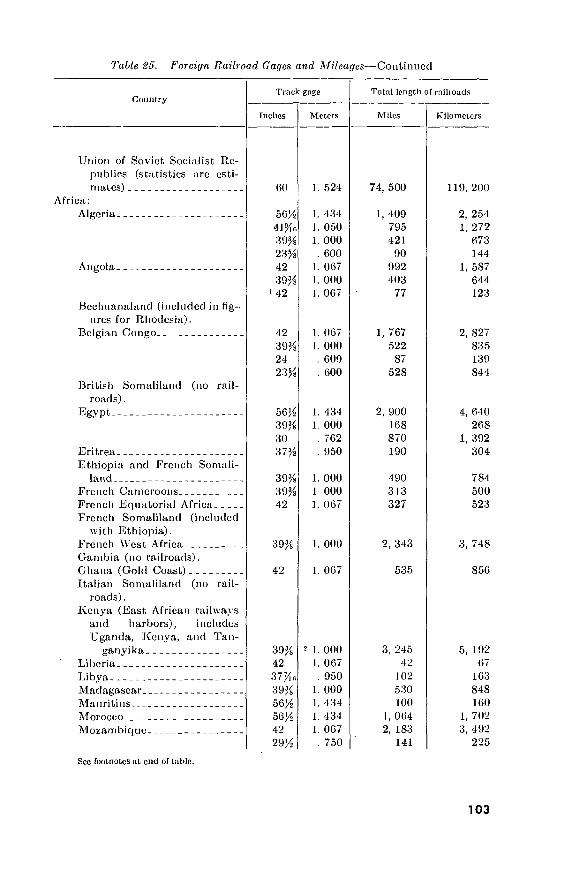
Table %5. Foreiyn Railroad Gages and Mileages—Continued
Country
Union of Soviet Socialist Re- publics (statistics arc esti- mates)
Africa: Algeria
Angola.
Bechuanaland (included in fig- ures for Rhodesia).
Belgian Congo
British Somaliland roads).
Egypt
(no rail-
Eritrea Ethiopia and French Somali-
land French Camcroons French Equatorial Africa French Somaliland (included
with Ethiopia). French West Africa Gambia (no railroads). Ghana (Gold Coast) Italian Somaliland (no rail-
roads) . Keni'a (East African railways
and harbors), includes Uganda, Kenya, and Tan-
ganyika Liberia Libya Madagascar Mauritius Morocco Mozambique
Truck gage
Inches
60
56/2
41 ;Kr, 39% 23% 42 39%
i 42
42 39% 24 23%
56% 39^ 30
39% 39% 42
39%
42
39% 42 37%r, 39% 56% 56% 42 29%
Meters
1. 524
1. 434 1. 050 1. 000
. 600 1. 067 1. 000 1. 067
1. 067 1. 000
. 609
. 600
1. 434 1. 000
. 762
. 950
1. 000 1 000 1. 067
1. 000
1. 067
2 1. 000
1. 067 . 950
1. 000 1. 434 1. 434 1. 067
. 750
Total length of rnilioads
Miles
74, 500
1, 409 795 421
90 992 403
77
1, 767 522
87 528
900 168 870 190
490 313 327
2, 343
535
3, 245 42
102 530 100
1, 064 2, 183
141
Ivilomclers
119, 200
2, 254 1, 272
673 144
1, 587 644 123
2, 827 835 139 844
4, 640 268
1, 392 304
784 500 523
3, 748
850
5, 192 67
163 848 160
1, 702 3, 492
225
See footnotes at end of table.
103

Tabic 25. Foreign Railroad Gages and Mileages—Continued
Country Truck gage
Incites Meters
Total length of railroads
Miles Kilometers
Nigeria-
Nyasaland Portuguese Guinea (no rail-
roads) . Reunion Rhodesia (North and South)
(includes Bcchuanaland). Sierra Leone Sudan
Tanganyika, Togo Tunisia
Uganda (details included in figures for Kenya) (East African railways and har- bors).*
Union of South Africa
North America: Alaska
Canada
Mexico
United States,
South America: Argentina
Bolivia.
Brazil __
British Guiana
Sec footnotes at end of table.
42 30 42
39%
42 42 42 24 39% 39% 56% 39%
42 24
56% 36 56% 42 56% 36 56% 36
66 56% 39% 29% 39% 30 63 39% 29% 24 23% 56% 42
1. 067 . 762
1. 067
1. 000
1. 067 . 762
1. 067 . 609
1. 000 1. 000 1. 434 1. 000
1. 067 . 609
1. 434 . 914
1. 434 1. 067 1. 434
. 914 1. 434
. 914
1. 677 1. 434 1. 000
. 750 1. 000
. 762 1. 600 1. 000
. 760
. 609 . 600
1. 434 1. 067
1, 904 133 316
78
2, 436 311
2, 011 19
1, 581 278 300
1, 005
12, 578 793
536 110
44, 741 705
11, 154 1, 329
236, 415 584
15, 192 2, 131 9, 280
635 1, 866
20 1, 556
18, 338 452
29 117 60 18
3, 046 212 505
124
3, 897 497
3, 217 30
2, 529 444 480
1, 608
20, 124 1, 268
857 176
71, 585 1, 128
17, 846 2, 126
378, 264 934
24, 307 3, 409
14, 848 1, 016 2, 985
32 2, 489
29, 340 723
46 187
96 28
104

Table 25. Foreign Raihoad Gages and Mileages—Continued
Country Track gage
Inches Meters
Total length of railroads
Miles Kilometers
Chile.
Colombia-
Ecuador. .
French Guiana (no railroads). Paraguay
Peru.
Surinam (Dutch Guiana). Uruguay
Venezuela.
Central America: British Honduras (no rail-
roads) . Costa Rica El Salvador Guatemala Honduras
Nicaragua- Panama
60 56)4 42
30 23% 39% 36 56% 42 29%
(3)
56% 39% 31% 30 29% 24 56% 42 36 30 29% 23% 39% 56% 35% 29% 42 39% 36 24
42 36 36 42 36 42 60 36
1. 677 1. 434 1. 067 1. 000
. 762 . 600
1. 000 . 914
1. 434 1. 067
. 750 (3)
1. 434 1. 000
. 800 . 762 . 750 . 009
1. 434 1. 067
. 914
. 762
. 750
. 600 1. 000 1. 434
. 895
. 750 1. 067 1. 000
. 914
. 609
1. 067 . 914 . 914
1. 067 . 914
1. 007 1. 524
. 914
1, 808 504 440
2, 429 181 193 904 487
94 500 112 122
312 59 57
144 ' 67
11
1, 148 58
734 42 27
151 107
1, 876 3 9
290 85
108 220
411 385 725 489 286 235 150 105
2, 886 806 704
3, 886 289 308
1, 446 779 150 800 179 195
499 94 91
230 107
17 1, 836
92 1, 174
67 43
241 171
3, 001 5
14 464 136 172 352
657 616
1, 160 782 457 376 240 168
"See footnotes at end of table.
105

Table 25. Foreign Railroad Gages and Mileages—Continued
ft
C-
F- c
f
fc Ï.
Country
Caribbean: Cuba._
Dominican Republic.
Haiti
Jamaica Puerto Rico_ Trinidad
Australasia: Australia
New Zealand. Tasmania
Pacific Islands: Formosa
Hawaii _ Hainan.
Indonesia: Borneo. Java
Madura. Sumatra.
Philippines
Approximate grand totals.
Truck gage
Inches
56J¿ 36 30 42 30 42 30
5GM 30% 56%
63 56% 42 30 24 42 42
42 30 36 42
39% 40 42 23% 42 42 30 42
Meters
1. 434 . 914 . 762
1. 067 . 762
1. 067 . 762
1. 434 1. 000 1. 434
1. 600 1. 434 1. 067
. 762 . 609
1. 067 1. 067
1. 067 1 . 762
. 914 1. 067
1. 000 1. 168 1. 067
. 600 1. 067 1. 067
. 762 1. 067
Total length of railroads
Miles
2, 666 57 68 86 62
112 75
208 271 105
6, 102 7, 294
12, 835 114
30 3, 530
723
493 109 20
167
116 25
2, 665 50
140 846 305 655
803, 056
Kilometers
4, 265 91
108 137
99 179 120 332 433 168
9, 763 11, 830 20, 536
182 48
5, 648 1, 156
788 174 32
267
185 40
4, 364 80
224 1, 353
488 1, 048
1, 283, 157
1 Being converted from inch r Kenya and Uganda. 3 Not available 3 Plus 2S nnles of dual gage.
1 yt
b
Tt
I ?
106
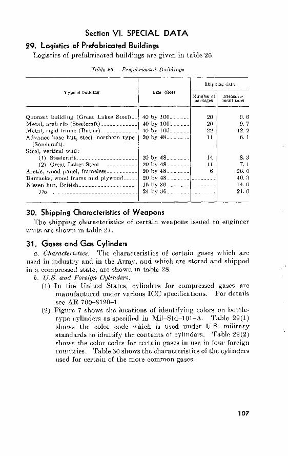
Section VI. SPECIAL DATA
29. Logistics of Prefabricated Buildings Logistics of prefabricated buildings are given in table 26.
Table 26. Prefabricated Buildings
Type of building Size (feet)
Shipping data
Number of packages
Measure- ment tons
Quonset building (Great Lakes Steel)__ Metal, arch rib (Steelcraft) Metal, rigid frame (Butler) Advance base hut, steel, northern type
(Steelcraft). Steel, vertical wall:
(1) Steelcraft (2) Great Lakes Steel
Arctic, wood panel, frameless Barracks, wood frame and plywood Nissen hut, British
Do
40 by 100. 40 by 100. 40 by 100. 20 by 48..
20 by 48. 20 by 48. 20 by 48. 20 by 48. 16 by 36. 24 bv 36.
20 20 22 11
14 11
6
9. 6 9. 7
12. 2 6. 1
8. 3 7. 1
26. 0 40. 3 14. 0 21. 0
30. Shipping Characteristics of Weapons The shipping characteristics of certain weapons issued to engineer
units are shown in table 27.
31. Gases and Gas Cylinders a. Characteristics. The characteristics of certain gases which are
used in industry and in the Army, and which are stored and shipped in a compressed state, are shown in table 28.
b. U.S. and Foreign Cylinders. (1) In the United States, cylinders for compressed gases are
manufactured under various ICC specifications. For details see AR 700-8120-1.
(2) Figure 7 shows the locations of identifying colors on bottle- type cylinders as specified in Mil-Std-101-A. Table 29(1) shows the color code which is used under U.S. military standards to identify the contents of cylinders. Table 29(2) shows the color codes for certain gases in use in four foreign countries. Table 30 shows the characteristics of the cylinders used for certain of the more common gases.
107

108
Ií’HÍí' '■■«'I
T(ü>lc S17. Sla'ii/jinti Characterislicts of Weapons
Nomenclature
Carbi nu, cal. .130, Ml Cun, automatic, 20 nun.,
M24A1. Gun, machine, cal. .00,
Browning MIOIOAI, w/cq|j Gun, machine, cal. .50,
Browning, MO, aircraft. Gun, machine, 7.62 mm.,
M60. Gun, submachine, cat. .45,
M3 and M3A1. Gun, machine, cal. .30,
Browning 1919A6 w/eqp. Mortar, 60 mm., M5 Mount.. Mortar, 81 mm., M4 Mount. Mount, machine gun, M91 Pistol, auto. cal. 145 M-
1911A1 w/50 extra mags. Rifle, recoilless, 57 mm.,
M18A. Rifle, recoilless, 75 mm., M20. Rifle, recoilless, 106 mm.,
M40A1, w/eqp.
Item wcinht
(noumls)
5. 5 100. 0
37. 0
64. 5
45. 0
8. 0
39. 0
45. 5 136. 5
10. 0 2. 5
44. 5
114. 5 840. 0
Type container
Wood box. Wood box.
Wood box
Wood box
Wood box
Wood box
Wood box
Wood box Wood box Wood box Wood box
Wood box—
Wood box. Wood box.
Items per con-
tniner
10 1
1
1
2
10
1
1 1 3
25
Dimensions of contiiinor
Lonpth (feet)
3. 48 7. 1
3. 8
5. 1
3. 1
1. 65
3. 8
2. 34 4. 68 2. 8 2. 82
5. 55
7. 12 7. 3
Width (feet)
1. 42 9. 58
. 58
. 687
1. 7
1. 26
. 56
1. 16 1. 5 2
. 98
1. 39
1. 47 3. 2
Height (feet)
0. 98 . 792
. 75
. 843
1. 1
1. 42
. 75
11. 2 1. 25 1. 08
. 868
1. 33
1. 14 3. 8
Cubic feet
4. 82 5. 39
1. 65
2. 96
6
2. 96
1. 6
3. 04 8. 59 6 2. 38
10. 329
11. 93 77. 5
Shipping weight
(pounds) per con- tainer
112. 0 170. 0
55. 0
97. 0
123. 5
128. 0
58. 5
75. 0 210. 0 120. 0 105. 0
115. 0
240. 0 1, 110. 0
Measure- ment
tons per container
. 12
. 135
. 04
. 074
. 15
. 074
. 4
. 076
. 214
. 15
. 059
. 258
. 298 1. 94
Container per vehicle
2J4*ton truck
40-root, 40-ton UK. (box) car
(70 percent cubage capac-
ity load)
58 47
172
77
65
63
178
95 33 47 76
28
24 4
450 400
1, 315
718
270
630
1, 355
715 252 362 760
212
182 28

Rifle, U.S., cal. 130, Ml Rifle, 7.62 mm., M14 Rocket launcher, 3.5-in.,
M20. Sniperscope
9. 50 8. 7
17. 0
136. 0
Wood box Wood box VCI package.
Wood box
10 10 4
4. 08 4. 23 3. 01
3. 4
1. 54 1. S 2. 79
1. 5
1. OS
1. 1
1. 33
1. 5
6. 82 8
11. 23
7. 4
104. 0 200. 0 135. 0
188. 0
17 2 28
185
42 35 25
39
319 271 194
294

A'- _THREADSNOT TOBE PAINTED
LOCATION OF COLORS ON GOVERNuENT-OWNEO CYLINDERS
COMMERCIAL \ IDENTIFICATION TA
IB. -j-B”- A"
3 COLOR OF CAP
" SAME AS COLOR OF A. A'OR A"
-THREADS NOT TO BE PAINTED
LOCATION OF COLORS ON COMMERCIAL-OWNED CYLINDERS
LOCATION DIMENSIONS
ON CYLINDERS FOR MEDICAL GAS MIXTURES. 1“ SPACE AND BAND C ARE LOCATED IMMEDIATELY BELOW BANDS B’ OR BM
CYLINDERS FOR
OVERALL LENGTH
L
SHOULDER COLOR(S)
CYLINDER COLOR BAND(S)
COMMERCIAL IDENTIFICATION
MEDICAL GAS MIXTURES
OTHER GASES
MEDICAL GAS MIXTURES
30" AND UNDER
2" ?"
FROM CYLINDER TOP TO BOTTOM OF NECK RING
M” SPACE TO BE OMITTED IF BANDS B L C ARE OF DIFFERENT COLORS
Figure 7. Location of colors in bottle-type cylinders.
no

îiii
L*:
Tabic 28. Characteristics of Oases
:o
Gas
Acet^'lenc Aminonia Argon Curbon dioxide Chlorine Ethylene oxide Helium Hydrogen Hydrogen eyunide Methyl chloride Nitrogen Oxygen Petroleum gas—Butane
pane. Refrigerant Sulphur dioxide
pro-
Color
None None None None Greenish yellow. None None None None None None None None
None. None.
Odor
Garliclike Pungent None Paint Disagreeable Pungent None None Peach blossom. Etherlike None None Sewer gas
None Rotten eggs.
Weight when compared to air
Lighter Lighter Slightly heavier. Much heavier Much heavier Lighter Much lighter Much lighter Lighter Heavier Slightly lighter.. Slightly heavier. Heavier
Heavier Much heavier.
Physical state as shipped
Dissolved. Liquid Liquid Liquid Liquid Liquid Gas G as Liquid Liquid Gas Gas Liquid
Liquid. Liquid.
Physical clFcct
Anesthetic. Irritant. None.1
None.1
Irritant. Irritant. None.1
None.1
Toxic. Anesthetic. None.1
None. Anesthetic.
None.1
Irritant.
1 Excessive amounts cause suffocation.

11
2
í1«/)/« 29(l). Military Standard 101A—Color Code for Compressed Gas Cylinders and Pipelines
Title Top A Band B
Acutylune Acrolein Aerosol insecticide Air, oil pumped Air, water pumped Ammonia Argon, oil pumped Argon, water pumped Boron trichloride Boron trifluoride Bromoacetone Bromochloromethane Bromochloromethane (fire only) Bromofluoromethane Bromofluoromethano (fire only) Butadiene Carbon dioxide Carbon dioxide (fire only) Carbon monoxide Chloroacetone Chlorine Chlorine trifluoride Chloropicrin Cyanogen Cyclopropane, medical Cyclopropane, medical- Dibromodifluoromethane
Yellow. Yellow. Buff Black.. Black.. Brown _ Gray.. Gray.. Gray.. Gray.. Brown _ Buff... Red Orange Red Yellow. Gray.. Red Yellow. Black.. Brown. Brown . Brown. Yellow. Orange Orange Buff...
Yellow Brown Buff Green Green Yellow White White Brown Brown Black Gray Gray White White White Gray Red Brown Brown Brown Green Orange Brown Yellow Chromium plated White
Band C Body
Yellow Black Buff Green Black Orange White Gray Gray Brown Black Buff Red Gray Gray Buff Gray Red Brown Black Brown Brown Orange Yellow Blue Chromium plated. Buff
Yellow. Brown. Buff. Black. Black. Orange. Gray. Gray. Brown. Brown. Brown. Buff. Red. Orange. Red. Buff. Gray. Red. Brown. Brown. Brown. Brown. Brown. Brown. Blue. Chromium plated. Buff.

11
3
DibromodifluoroincUutnu (tire only)
Difliiorochloroetliaiie Difluoioethane
Dimcthylamine, anhydrous Dimcthylcthcr
Dispersant, DiehlorodillnoroineUiane-Difluoro-
cthanc Mix. Ethane Ethyl chloride
Ethyl nitrite
Ethylamine, anhydrous
Ethylene, industrial
Ethylene, medical Ethylene oxide F-l 1, TrichloroHuoromcthane
F-12, Dichloroditluorometliane F-i:3, ChlorotriHuoromethane
F-2J, Dichlorofluoromethane
F-22, Chlorod if! uoromethane F-l 13, Trichlorotrifluoroethune
F-J14, Dichlorotetrafluoroethane
F-124A, Chlorotctrafluoroethane
Fluorine
Fumigant, Carbon dioxide-Ethylene oxide Helium, oil free or medical
Helium, oil pumped
Helium-Oxygen
Hydrogen
Hydrogen bromide Hydrogen chloride, anhydrous
Hydrogen cyanide, anhydrous
Hydrogen fluoride, anhydrous
See footnotes at end of table.
Bed Gray...
Gray__.
Yellow . Yellow.
Buff...
Yellow. Buff...
Yellow.
Yellow.
Blue... Yellow.
Yellow.
Orange. Orange
Orange.
Orange. Orange
Orange. Orange.
Orange Brown.
Buff...
Buff... Gray..
Bull' >..
Yellow. Black..
Brown.
Yellow. Green..
White.. Yellow.
Yellow.
Blue Brown.
Gray...
Blue
Blue
Buff Blue Yellow..
Blue
Blue
Orange.. Orange.. Orange..
Orange..
Orange.. Orange..
Orange. _
Orange_ Green
Blue Gray
Orange..
White 2. Black
Brown. .
White
Brown..
Brown._
Red... Yellow.
Orange. White..
Buff... Gray...
Yellow.
Yellow.
Buff
Blue
Buff... Blue
Buff... Orange.
Orange.
Orange.
Orange- Orange.
Orange.
Orange-
Orange.
Green..
Buff...
Gray-
Gray... Green..
Yellow.
Brown.
Brown _
White.. Brown .
Red.
Orange. Orange. Buff:
Buff.
Buff.
Yellow.
Buff.
Buff.
Buff. Buff.
Blue.
Buff. Orange.
Orange.
Orange. Orange.
Orange. Orange.
Orange.
Orange. Brown.
Buff.
Gray.
Gray. Green.
Yellow.
Brown.
Brown. Brown.
Brown.
.4;

11
4
k
Table 29(1). Military Standard 101A—Color Code for Compressed Gas Cylinders and Pipelines—Continued
Title
Hydrogen sulfide Krypton, oil pumped Krypton, wnter pumped Manufactured Gas—(Specify) Coal, oil, water,
producer, etc. Methane Methylamine Methyl bromide Methyl bromide (fire only) Methyl chloride Methyl mercaptan Methyl sulfide Methylene chloride Natural gas Neon, oil pumped Neon, water pumped Nickel carbonyl Nitric oxide Nitrogen dioxide Nitrogen, oil pumped Nitrogen, water pumped Nitrosyl chloride Nitrous oxide Oxygen, medical Oxygen, aviator’s Oxygen Oxygen-Carbon dioxide
Top A
Brown. Gray... Gray... Brown.
Yellow. Yellow. Brown. Red. _. Yellow. Brown. Yellow. Gray... Yellow. White.. White- Yellow. Brown _ Brown _ Gray... Gray... Brown . Blue White.. Green.. Green.. Gray 1.
Band B
Yellow. Buff... Buff... Yellow.
White... Brown _. Black... Brown _. Biown.. Yellow.. Brown.. Blue Brown.. Buff.... Buff White... Buff Buff Black... Black. _. White. _. Blue Green... White. _. Green... White 2.
Band C
Brown. Buff... Gray... Yellow.
Yellow. Yellow. Brown. Red Orange- Yellow. Buff... Orange. Yellow. Gray... Buff... Yellow. Brown. Buff... Gray.— Black. - White--
Blue Green.. Green.. Green.. Green..
Body
Brown. Gray. Gray. Yellow.
Yellow. Buff. Brown. Red. Orange. Brown. Brown. Orange. Yellow. Gray. Gray. Brown. Brown. Brown. Gray. Gray. Brown. Blue. Green. Green. Green. Green.

ns
Petroleum Gas—(Specify) Aeetogeii, Butane, Butane-Propane, Butene-1, Cyclopropane, Isobutane, Isobutylene, Neopetane, Propane, etc.
Phcnylcarbylamine chloride Phosgene Propylene Sulfur dioxide Sulfur hexafluoride Tetrafluoroethylene, inhibited Trimethylamine, anhydrous Vinyl bromide Vinyl chloride Vinyl methyl ether, inhibited Xenon, oil pumped Xenon, water pumped
Yellow
Brown. Brown. Yellow Brown. Gray.. Buff.. Yellow Buff__ Yellow. Yellow White. White.
' A' or A" for medical gus mixtures. - B' or B" for medical gas mixtures.
Orange
Gray.. Orange. G ray... Gray... White. White. Blue... Blue... Orange Black.. Black.. Black..
Yellow. Yellow.
Gray.. Brown. Buff... Brown. Black.. White. Orange Blue... Buff... Buff... Black.. Gray..
Brown. Brown. Buff. Brown. Gray. Buff. Buff. Buff. Buff. Buff. Gray. Gray.
Tabla ¡¡9(2). Fnreiyii Ci/Uniler Colors
C! as England Australia Japan Italy Germany
Acetylene Carbon dioxide. Freon 12 Helium Hydrogen Methyl chloride. Nitrogen Oxygen
Purple. Black..
Browi lied..
Gray.. Black.
Maroon Brown Light green. Gray Signal red.. Light green. Dark gray.. Black
Brown.
Red.
Purple. Black..
Orange. Yellow.
Red.
Green. White-
Yellow.
Red.
Green. Blue.

9 L
l
^¡' it*
Table SO. Characteristics of Cylinders Used for Certain Gases
Gas
Acetylene
Ammonia
Carbon dioxide..
Chlorine
Helium Hydrogen
Methyl chloride
Standard cylinder characteristics
ICC spec, number
stamped on shoulder
4A
3A
3A
3A 3A
4B
Capacity cu. ft. of gas at atmospheric
pressure
Capacity (lb. liquid)
10 40
100-110 225 300
220 115
220-240
Outside diameter (inches)
100 150
20
50 10
16 150
15 30 93
100
4^o
7tf 8/2
12/ 12/ 12/ 15 7/
8/ 4/
6/ 10/
9 7/ 9 7 8/
10/ 10/
Length (inches)
13/ 26 30 36 39 52/ 53 29/
51 21
13/ 48/ 51 43 51 21/2
27 49/ 49/
Max pressure (p.s.i. at 70°
F.)
250
480
2, 015
Weight empty (lb.)
480
2, 015 2, 015 2, 015
300
92 100
68
108
120 120 120
Weight full (lb.)
100 196
88
158
122 121 121
Outlet valve threads 1
Internal-left.
Internal-right.
External- right.
External- right.
(2) External-left.
External-right.

Nitrogen (\v;iLer-puiii[tod)-(uil- pumpixl).
Oxygen
Sulfur dioxide
3A 22U
22« 9 y
51 51
2, ÜL5 120
120 137 137
3A
3B
12
110
220-240 150
4JÏ« 7 >8
ioy2
43
491
2, 015
300
79 120
88 137
Internal-right. 1 nternal-left.
External-right.
External-right.
1 l'rom U.S. Dept, of Conuneice. National Bmouu of Snuulimlá, Supplement to Screw-Thread Standards for Federal Services, 1!)‘14 (Issued 15 June 11)41)), Supplement to Handbook H2S (1944).
2 Water-pumped' Internul-nght. Oil-pumped: Internal-left.

32. Processing and Packing a. General. Processing and packing supplies is a highly important
step connected with the shipment or storage of items so that when requh-ed they will be in usable condition. Steps in the above include proper cleaning, application of preservatives, packaging, and crating. Processing materials and their sources are dealt with in SB 38-100.
b. Cleaning. The first step in the procedure is the proper clean- ing of the item. No preservative method will protect a part from corrosion if contaminating residues (deposits foreign to the composi- tion of the part) are present on the surface.
(1) Some causes of corrosion are: (а) Moisture. (б) Perspiration from handling. (c) Residual soldering, welding, or brazing fluxes. (d) Cutting, cooling, buffing, or grinding compounds. (e) Dust and chemical deposits.
(2) There can be no standard choice or method of cleaning, since the cleaner selected and the method used are dependent upon the composition, nature, and construction of the part; the nature of contaminants to be removed; the degree of cleanliness required; and the availabilit}^ of cleaning materials.
(а) The extent of cleaning is determined by the surface to be cleaned, varying from a highly finished part to a rough casting. Naturally, the utmost care must be taken to remove even fingerprints from highly finished surfaces.
(б) There are four approved types of cleaning materials, plus fingerprint remover or neutralizer. These are:
1. Petroleum solvent (Stoddard). 2. Alkaline cleaners. S. Emulsifiable solvents. 4- Vapor degreasers (trichlorethylene and perchlorethylcne). 5. Methanol (fingerprinting neutralizer).
(c) The parts must be dried after cleaning and before apply- ing the preservative. Preferably, drying is done with compressed air or by oven-drying. Drjdng with a cloth is not recommended and should be used only when compressed air or oven-drying is impracticable.
c. Preservatives. The types of preservatives recommended are given in tabic 31. Further information may be obtained bjr reference to TM 38-230. The application of preservatives may be done by dip- ping, spraying, brushing, flow-coating, or slushing. Dipping is the preferred method.
d. Methods of Preservation. There are six basic methods of preser- vation, and a number of submethods, which are used in the processing
118

11
9
Table 3L. Preservative Compound Chari1
Type
r-l
P-2
P-2
P-5
P-0
P-7
Preservativo
Thin film piescrviilivo (hard-drying, cold application).
Thin film presci vative (soft film, cold application).
Thin tilín preservativo (soft, cold applica- tion, water dis- placing).
Heavy preservative (hot application, hard film).
Medium preservative (hot. application, soft tilín).
Light preservative (hot application, soft film).
Medium preset vative oil (cold application).
M ilitury
M1L-C- icm.
grade 1.
MIL-C- 1Ü173, grade 2
MIL-C- 10173, grade 3.
M1L-C- 117110, class 1.
MIL-C- ii7<m, class 2.
MLL-C- 117%, class 3.
M1L-L- 3150
Aeronaii' tical
Army Navy
M1L-C- 18487.
Application 2 method and temp.
Brush, dip, oi spray. 40° F.-050 F.
Description 3
Brush, dip, or spray. 40° 1''.-%° F.
B: ush, dip, or spray 4U0 F. %0 F.
Brusii or dip. Maxi- mum Lcmpcratuie of application 200° F
Brush, dip, or spray. Maximum temper- ature of application 1%° F.
Brush, dip, or spray. Maximum tompeia- tme of application 1SU° F.
Brush, dip, or spiay. 60° F.-J200 F.
Dries to a hard film. Thick- ness 0.004 in. (max.). Sol- ventcutback. Flash point 100° F.
■Non - hard - drying film. Thieknoss0.002in. (max ). Solvent cutback. Flash point 100° F
Non - hard - drying film. ThicknessO.001 in. (max.). Solvent cutback. Flash point 100° F. Also remov- able in hot water.
Thick, hard drying, greasy film.
Thick, medium firm, greasy film.
Thin, soft, greaselike film...
Lube oil with added inhibi- tors. Similar in physical properties to SAE 30. Pour point 20° F.
Use1
On metals under outdoor conditions. Primarily for parts not having highly finished surfaces. Not satis- factory for parts oi equipment dam- aged by solvent removal. NOT FOR INTRICATE ASSEM- BLIES. Can frequently be used without overwrap.
On metals indoors where easy ie- movabihty is desired. Usually re- quires overwrap.
To displace water from pieviously wet surface. Usable for temporary protection.
Protection of highly finished parts of simple design for prolonged periods.
Pi election of highly finished parts of relatively simple design for pro- longed periods. Requires over- wrap.
Protection of highly finished parts of complex design which can be cleaned. Especially adapted to preserving antifriction bearings. Requires overwrap.
Protection of oil-lubricated and simi- lar operating parts. Should be sup- plemented by Method IA or II DO NOT USE FOR INTER- NAL COMBUSTION EN- NFNES. Must be lemovod prior to use. See footnotes at end of (able.

12
0
Table SI. Preservative Compound Chart 1—Continued
Type
P-8
P-9
P-10
P-11
P-12
P-13
Preservative Military
Light preservative oil MIL-L- (cold application). 3503.
Very light preservative oil (cold applica- tion).
MIL-Xr*
G44.
Engine preservative oil.
Preservative grease (application as re- quired).
Anti-friction bearing preservative (hot application).
Wax emulsion M1L-W- 3088.
Aeronau- tical
Army
MIL-C- 0529.
MIL-L- 21260, Grade 1, 2, or 3.
Navy Application 2 method and temp.
MIL-G- 3278.
MIL-C- 11700, Class 3.
MIL-L- 21200,
Grade 1, 2, or 3.
MIL-G- 10924.
MIL-G- 16908.
Brush, dip, or spray. 60° F.-1200 F.
Brush, dip, or spray. 60° F.-1200 F.
Brush, dip, or spray. 00° F.-1200 F.
Description3
Brush. 30° F.-1200 F..
Dip. 170° F.-1800 F._.
Spray, dip, or wipe. Room temperature.
Lube oil with added inhibi- tors. Flash point 300° F. Pour point 50° F. Similar in physical properties to SAE 10.
Lube oil with added inhibi- tors. Flash point 275° F. Pour point 70° F.
Engine lubricating oil with corrosion inhibitors, in- cluding hydrobromic acid neutralizers. Pour point MIL-L-21260, grade 1, 10° F. MIL-L-21260, grade 2, 0° F. MIL—C— 6529, 10° F. Flash point: MIL-L-21260, grade 1, 360° F. MIL-L-21260, grade 2, 390° F. MIL-C- 6529, 350° F.
Lithium soap grease
Medium dark soft petrola- tum base material. Flash point 350° F.
Aqueous uniform combina- tion of emulsifying agents, waxes, and resins together with suitable rust inhibi- tors. Softening point 165° F.
Use 4
Protection of machine guns and small arms, and operating equipment. Must be removed prior to use in Arctic or in an airplane.
Protection of machine guns and small arms, and operating equipment. Need not be removed from guns prior to use.
Protection of internal surface of in- ternal combustion engines and other intricate assemblies.
Protective grease for lubricated bear- ings. Particularly suitable for equipment which must operate at both very low and high temper- atures.
Preservative grease for lubricating bearings and other semi-complex parts from wh ich it can be removed.
Dry lubricant and rust inhibiting coating for general weatherproofing when applied to articles.

121
P» 15
P-ir,
P-17
P-18
Corrosion preventivo for food Imndlin^ machinery and equipment (non- toxic).
Hydiaulic system pre- servative oil.s
Thixotropic preserva- tive oil.
[nstrunient brui in# lireseivative oil.
Volatile corrosion in- hlhitor.
MIL-C* 10*382.
M 1 L-C-
5545.
MM, L tiusn.
13420.
Si>iay room teuiper- atme.
Brnsli, <iip, oi jKpniy. 120° K. ISO0 b\
Brush, dip, oi spray. Room temperature
Wrap of VCi floated matenal.
Uniform mixture of white microcrystalline wax, lano- lin corrosion inhibitor, 2-Amlno-2-Methyl-1- Pro- panol, and solvent P-S- 001 produces a thin film easily removed. Flash point 100° F.
Luire oil Nvith added thick- eners and corrosion inhibi- tors with thixotropic be- havior. Flash point 350° F.
Synthetic base luhricatniii oil of low volatility with additive materials to im- part oxidation stability and corrosion protective properties. Pour point 70° F. Flash point 305° F.
Materials coated or impreg- nated with a corrosion in- hibitor which will vola- tilize and whose vapors
• prevent rusting of metal sm faces.
Food handling equipment and ma- chinery.
Protection of internal and external sm faces and assemblies where run- o(T cannot be tolerated. Primarily for aircraft engines.
Aircraft instruments and electronic equipment.
Protection of ferrous metals, ap- proved iionferrous metals and ap- proved nonmetallic components during shipment, handling, and storage.
1 Warning.—This table is intended to correlate specification numbers with certain generally accepted typos. It does not connote interchangeability, except that any compound listed under MILITARY may be used for any other with the same P number. It may, however, be used for the selection of alternative preservative com- pounds when the specific preservatives are not in stock or available from another source insufficient time to accomplish the necessary preservation and when Ulereare no specific orders to the contrary. 'Phis tabic is not intended to be used by contractors for the selection of alternate preservative materials unless such selection privilege is included in their contracts.
■ These values are typical. Consult can label for detailed information. 3 Those arc typical of the most easily recognized properties. 4 These aie the most common uses. There arc many others. 3 Specifications for hydraulic preservative oils have not been listed because of vari-
ations m system requirements. Hydraulic preservatives used will be subject to approval by the procuring agency.

of parts and equipment. The method used depends upon the nature of the material and equipment and the degree of protection required.
(1) Method I. Preservative coating, with greaseproof wrap when required. Method I is used for the protection of spare parts and other equipment for shipment and storage, when the nature and construction of the items allow ready appli- cation of a corrosive protective compound film by dipping, spraying, flushing, brushing, or fogging.
(2) Method I A. Water-vaporproof inclosure with preservative as required. Method IA is intended to afford adequate pro- tection against corrosion caused by water or water vapor, and is applied to parts and equipment where critical func- tioning surfaces held to close tolerances are involved. There are sixteen submethods.
(3) Method IB. Strippable compound coating (hot dip). The use of Method IB is limited to parts that have no deep recesses or complexities of structure which would prevent complete removal of the plastic coating, and whose design or contour is simple. There are two submethods.
(4) Method IC. Waterproof barrier (with pireservative as required). Method IC is intended to afford adequate protection against deterioration caused by direct entry of water. This is effected by a sealed waterproof or water-resistant barrier permitting only water-vapor penetration to the preserved part. There are six submethods.
(5) Method II. Water-vapor proof barrier with desiccant and with preservative when required. Method II is used for items of a highly critical nature requiring the highest degree of pro- tection from damage by the effects of water vapor. It is applicable to mechanical or electrical items including assem- blies with functional components which, by their nature, cannot be treated with a preservative. It involves inclos- ing the item(s) or assembly with the required amount of activated desiccant within a watcr-vaporproof barrier. There are six submethods.
(6) Method III. Packaging for mechanical and physical protec- tion only. Items packaged by Method III should be tied together or inclosed with «Tappings, bags, cartons, boxes, or other containers as applicable, to the extent necessary to provide protection from hazards of contamination and physical damage encountered in general handling, storage, and issue.
e. Packaging and Crating. (1) General. In selecting a container for shipping, the following
factors should be considered: (a) Suitability of articles to be packed.
122

(b) Processing used for jjrotection against corrosion. (c) Availability. (d) Cubic displacement. (ß) Ease in handling and storing. (f) Type of load.
(2) Cushioning material. Soft material should be used as cush- ioning for delicate or fragile items; highly finished surfaces; small projections; protection of moisture-vaporproof and waterproof barriers, etc. However, cushioning material is not used in place of blocking material except in unavoidable cases.
(3) Lumber. The type and thickness of lumber to be used de- pends on the weight of the articles to be packed. Knots, cross-grain, bark, and other defects sharply reduce the strength of a board. In cutting out lumber, defects over one-third the board width are eliminated.
(4) Nails. (а) When nailing lumber together flatwise, nails arc driven
through and clinched about % inch if the combined thickness of lumber is 3 inches or less.
(б) For thickness over 3 inches, or for nailing a flat to an edge, unclinched nails are used in lengths as long as practicable without splitting the lumber. The minimum nail length to be embedded in the piece holding the point of the nail is two-thirds the nail length for lOd and smaller nails; 1/2 inches for 12d and larger mails (Spec. MJL-C-104).
(5) Gross weights. Maximum gross weights for various styles of boxes and crates are given in Table 32.
Table 32. Maximum Gross Weights for Boxes and Crates
Specification Type of container Maximum
gross weight, pounds
MIL-C-10-L MIL-C-132.
PPP-B-621_
PPP-B-60] _ MIL-B-107. PPP-B-591 _
Crate, sheated, wood, nailed Crate, unsheated, wood, nailed:
Style A Style A-l Style B Style C
Box, wood, nailed: Style 1 Styles 2, 2/2, 3 Styles 4, 5 Style 6
Box, wood, cleated, plywood Box, wood, wirebound Box, wood, cleated, fiberwood__
30, 000
1, 000 250
2, 500 500
1 50 1, 000
400 50
1, 000 300 200
1 Untier ceriain conditions, 100 lb. See Spec. PPP-B-621.
123

(6) Design. Figure 6 shows box styles. Table 33(1) shows minimum thicknesses of box parts for various styles of box and weights of contents, for domestic shipment and easy or average loads. Table 33(2) gives similar data for overseas shipments. For the case of difficult loads, and for other details, see Spec. PPP-B-621. The four groups of woods, as the term is used here, are as follows:
Group I
Alder, red Aspen (Popple) Basswood Buckeye Butternut Cedar
Chestnut Cucumbertree Cottonwood Cypress Fir (true firs) Magnolia
Pine (except southern yellow)
Poplar, yellow Redwood Sprue e Willow
Group II
Douglas-fir Hemlock
Larch, western Pine (southern yellow)
Tamarack
Group III
Ash (except white ash) Cherry Elm, soft
Maple, soft Sweetguin
Sycamore Tupelo
Group IV
Ash, white Beech Birch Elm, rock
Hackberry Hickory Pecan
Locust Maple, hard Oak
124

STYIE J SIVIÉ ? STYtE
Fitjure S. Box styles.
125

126
k.- y *r*> r
r-*ff
Table 33(1)
Boxes for domestic shipment, typo 1 (easy) and type 2 (average) loads; minimum thickness of sides, tops, bottoms, and ends, and minimum thickness and width of cleats.
Weight of contents
Exceed- ing—
Not ex- ceecllng-
Style of box
Groups I and II woods
Minimum thickness of sides,
tops, and bottoms1
M Inimum thickness of ends 1
Minimum thickness and width of cleats
Groups III and IV woods
Minimum thickness of sides,
tops, and bottoms 1
Minimum thickness
of ends
Minimum thickness and width of cleats
Pounds
50 50 50 50
100
100
250
Pounds
50 50 50 50
100
100
100 100 250 250
.MOO
1
4, 5. 2 6
1 2
h 4/2, 5. 2
26 4, 4/2, 5. 2, 2J4, 3. 2, 2J4—.
5/io
yia Mo
% % % % % 'A A
%
Inch Inches
A by i%-
Ma by 1}'2_
Ms by 2%. A by 1%.
% by 2%. Ys by V/s. % by 2%_
Inch
A 'A
%
Mo Mo
Mo
Mo Mo
Inch
% %
Mo
A % % Mo
Ms
Inches
A by 1M- Mo by Vyi.
Mo by 1M. M by 1%.
Ms by 2M. Mo by 1%. Ms by 2)4.
■ Thicknesses ore minimum as stated; however, i( parts are surfaced on both sidci, hut not exceeding 100 pounds, il the hoxes have one-piece sides of sawed lumber and thickness may be Mm-hieli less than given in the tabic when the contents arc packed in interior containers.
! Style 1 and style 6 boxes may be used to carry a net weight exceeding 50 pounds 3 Weights of contents exceeding 400 pounds shall be considered typo 3 load.

53350G
Table S8{2)
a o
Boxes for overseas shipment, type ] (easy) and type 2 (average) load—detennination of minimum thickness of sides, tops, bottoms, and ends, and minimum thickness and width of cleats for styles 2, 2'A, 3, 4, and 5 nailed wood boxes.
Weight of contents
Exceed- ing—
Not ex- cceding-
Style of box
Groups I and II woods
M inimum thickness of sides,
tops, and bottoms 2
Minimum thickness of ends 2
Minimum thickness and width of cleats1
Groups III and IV woods
Minimum thickness of sides,
tops, and bottoms2
Minimum thickness of ends2
Minimum thickness and width of cleats1
Pounds
50 100 100 250 250 400 600
Pounds
50 100 250 250 400 400 600
1, 000
4, 4y2, 5 4, 4J4, 5 4, 4JÍ, 5 2, 2y2, 3 4, 4/2, 5 2, 2/2, 3 2, 2y2, 3 (See table IV).
Inch
%
fie Vu
Inch
%
% % % 2%2
2%2
Inches
% by l%— % by 2M— Vs by 2%... % by 2>4— 2%2 by 2%. % by 2%... 2%2 by 2%.
Mo
Mo
Me Ms
% Ys 'Me Ys % 'Me 3A
Inches
Ys by 1%. Ys by l/i. 'Mo by 2M. Ys by 2M. % by 2%. 'Mo by 2/. % by 2M.
1 When the inside depth of a box is 5 inches or less, end cleats shall not be used. Thickness of the ends shall be not less than the combined thickness of the end and cleat as specified for style 4 boxes, or if weight exceeds 400 pounds, as specified for style 2 boxes. Each side and end shall be made from one piece except when the end is approxi- mately square, a two-piece end with each end piece of approximately equal thickness
and with the grain of each piece running at right angles to the other may be used. Two-piece ends shall be nailed together with no less than two nails clinched.
2 If pieces $4 inch or more in thickness are surfaced two sides, the thickness may be
^2 inch less than the thickness as determined from the table requirements.
to N

CHAPTER 4
PRISONER-OF-WAR INCLOSURES
33. General FM 27-10 sets forth the general provisions by which our forces
will be governed in dealing with enemy personnel. TM 19-500 discusses the treatment and processing of prisoners of war and the security measures pertaining to them.
34. General Provisions a. Prisoners of war must be lodged in buildings or barracks which
are healthful, dry, heated, lighted, and protected from fire. Mini- mum dormitory area and air-space requirements will be the same as for troops at base camps.
b. Prisoners of war will have constantly at their disposal installa- tions conforming to sanitary rules, including the best practicable provisions for baths and showers. They must be enabled to take physical exercise and enjoy the open air. Sexes must be segregated.
c. In a theater of operations, prisoners of war will be sheltered in existing facilities when possible. If facilities must be built, they will be of temporary construction. For economy in area and fenc- ing, buildings arc best grouped in the center of the inclosure and space between them and deadline fences used for open air and exercise.
d. Prisoner-of-war labor will be used to the maximum in establish- ing, converting, maintaining, and dismantling security and housing facilities for themselves and their guards. They will not receive wages for work connected with installing, maintaining, or administer- ing the camps.
35. Security Provisions a. Stockade fences (except high masonry walls or impassible ter-
rain features) are temporary barriers only, to delay escape attempts and the entrance of unauthorized persons or contraband articles long enough to permit guards in towers or perimeter patrols to act.
b. Stockade fences of the following types are considered satisfactory : (1) A single chain-link woven steel-wire fence (2-inch mesh, 6-
to 9-gage wire) not less than 8 feet high, with top 45° exten- sion arms carrying three strands of barbed wire, and with barbed-wire concertinas anchored to the ground outside the fence.
128
(2) Two fences of the above type set 8 to 10 feet apart, with barbed-wire concertinas fastened to the top of the outer fence.
c. The delaying effect of the stockade fence is substantially increased by installing a deadline fence (a barbed-wire fence about 3 feet high which prisoners of war are forbidden to cross) about 8 to 10 feet inside the inner stockade fence.
d. Normally one gateway for one-way vehicular traffic, with a wicket for pedestrians, is adequate.
e. Guard towers with lights are installed to improve observation and to permit enfilading fire along fences and streets and inside the stockade.
36. Sequence of Development a. Prisoner-of-war inclosures are normally initiated in each army
and task force service area, reverting to communications zone con- trol and operation as the army rear boundary is advanced. Infor- mation for estimating the number likely to be captured is given in FM 101-10. Priority of other work in forward areas is likely to restrict construction, and initial prisoner-of-war inclosures will nor- mally consist of existing buildings or tents for shelter, pit-type latrines, expedient facilities for cooking and bathing, and a stockade fence. Such facilities should be designed for full development later by prisoner-of-war labor.
b. Table 34 gives basic data on a prisoners-of-war camp for 1,000 men in a temperate climate, using tentage. Table 35 gives similar data for prefabricated or standard frame construction. Table 36 gives the key to coding of the construction standard (the code digit given being the second digit of the four-digit number identifying the type of installation).
129

130
Table 84
P.W. CAMP, 1,000 MAN, TEMPERATE CLIMATE, STD 2, NEW CONST, TENTAGE (Site and Utility Dwg. 70-32).
Provides inclosure and accommodations for 1,000 Prisoners of War. All accommodations in tentage with earth floors. Bucket type latrines in tentage.
Tentage NP-3.120
Engineer Services Required: Water—5,000 GPD. Drain age—N on e. Electrical Connected Load—None.
Facility Size or unit Basis Facility No.
Number required
Material effort
ST MT Mil
1 TENTAGE 2 INTERIOR CONSTRUCTION.
Latrine, Bucket Type, (tent) 12 seats.
3 OTHER CONSTRUCTION
Fence, Security, Type X Fence, Security, Type Y Fence, Security, Vehicle & Man
Gate. Guard Tower Guard Tower Road, 1 Lane, 4” Macadam Sentry Box Sump, Fire Protection
Site Preparation.
Total
57,856 SF_
16' by 32'.
1.000 Ft. 1.000 Ft. Each
16'' by 16'. 16' by 24'. Mile 4' by 4'... 10,000 Gal.
Acre
Tent Area.
1 seat/20 men.
1/cor & 1/600' fence... 1/inclosure Installation Rds 1/main or comp, gate. Effective radius 500'.-
100' outside perim.
703292
723602
872102 872103 872104
872301 872401 851002
843110
932000
13 1. 03 8
8 1 0. 04 4 1
23
11
11
182
104 7
16
44 8 0 0 3
193
14
14
241
156 9
16
44 12 0 0 4
255
840
840
13, 580
7, 330 510
1, 410
1, 100 150 80
0 240
2, 760
14, 420
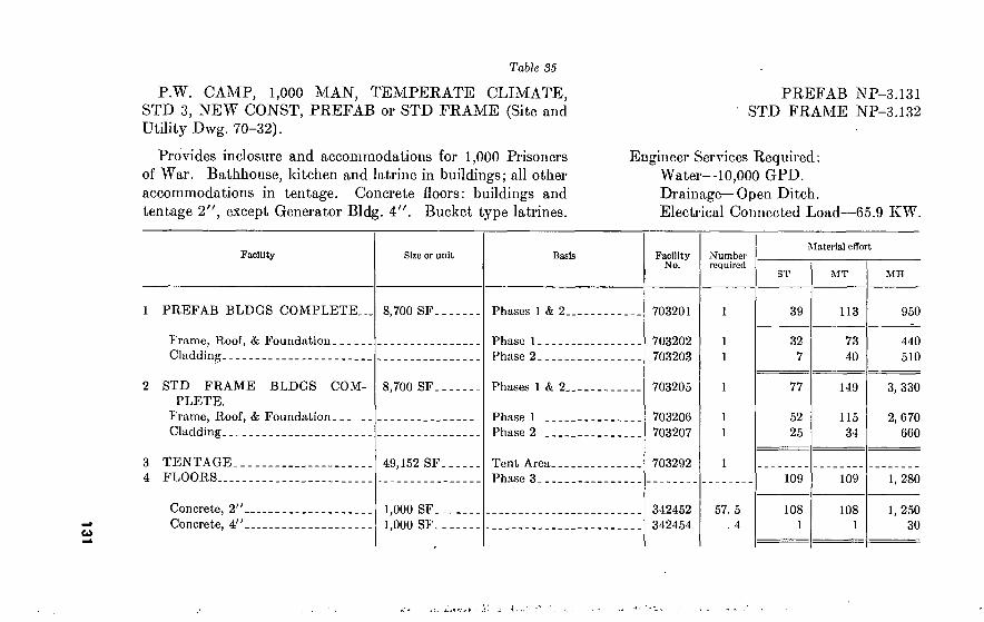
131 Table 35
P.W. CAMP, 1,000 MAN, TEMPERATE CLIMATE, STD 3, NEW CONST, PREFAB or STD FRAME (Site and Utility Dwg. 70-32).
Provides inclosure and accommodations for 1,000 Prisoners of War. Bathhouse, kitchen and latrine in buildings; all other accommodations in tentage. Concrete floors: buildings and tentage 2", except Generator Bldg. 4". Bucket type latrines.
l
Facility Size or unit Basis
PREFAB BLDGS COMPLETE. 8,700 SF Phases 1 & 2
Frame, Roof, & Foundation Cladding
Phase 1 Phase 2
2 STD FRAME BLDGS COM- PLETE.
8,700 SF
Frame, Roof, & Foundation Cladding
Phases 1 & 2.
Phase 1 Phase 2
3 4
TENTAGE FLOORS...
49,152 SF Tent Area. Phase 3...
Concrete, 2" Concrete, 4"
1.000 SF 1.000 SF
PREFAB NP-3.131 STD FRAME NP-3.132
Engineer Services Required : Water—10,000 GPD. Drainage—Open Ditch. Electrical Connected Load—65.9 KW.
Facility No.
703201
703202 703203
703205
703206 703207
703292
342452 342454
Number required
57. 5 . 4
Material effort
ST
39
32 7
77
52 25
109
108 1
MT
113
73 40
149
115 34
109
108 1
MH
950
440 510
3, 330
2, 670 660
1, 280
1, 250 30
t.,.-

13
2
Jf^' rî' - . 'ry IGtW •' • r^T¿'H i ■ v - *■’ -,
Facility Size or uuit
5 INTERIOR CONSTRUCTION
Bathhouse, 24 Shower Heads Generator Bldg., 3-30 KW. Units- Kitchen, 500 Man Latrine, Bucket Type, 12 Seats
• 20' by 50' 20' by 20' 40' by 60' 10' by 30'
6 OTHER CONSTRUCTION
Fence, Security, Type W Fence, Security, Type X Fence, Security, Type Y Fence, Security, Vehicle, & Man
Gate. Guard Tower Guard Tower Road, 1 Lane, 4" Macadam Sentry Box Sump, Fire Protection Utilities:
Water distribution Drainage Electric Distribution
Site Preparation
1.000 Ft. 1.000 Ft. 1.000 Ft Each
16' by 16'. 16' by 24'. Mile 4' by 4'... 10,000 Gal
Util Dwg. Util Dwg. Util Dwg. Acre
Table 35—Continued
Basis
1 sh hd/24 men 1/installation... 3 SF/man 1 seat/20 men..
1/cor & 1/600' fence 1/inclosure Installation Rds 1/main or comp gate Effective radius 500'
10 GPD/man Waste water ditch Light 100' outside perimeter..
Facility No.
723401 811203 720201 723601
Number required
872101 872102 872103 872104
872301 872401 851002
843110
703210 703211 703212 932000
Material ciTort
1. 97 11. 0
1. 03 8
8 1 0. 04 4 1
1 1 1
23
ST
45
14 11 14
6
MT
263
18 88
7 16
44 8 0 0 3
11 1
67 0
91
28 25 28 10
408
28 132
9 16
44 12 0 0 4
17 1
145 0
MIL
3, 680
1, 240 260
1, 560 620
2], 630
1, 540 6, 160
510 1, 410
1, 100 150 80
0 240
1, 780 190
5, 710 2, 760

13
3
Totals for Prefab Erection (1, 4, 5, & 6).
Totals for Std Frame Erection (2, 4, 5, & 6).
456
494
721
757
27, 540
29, 920
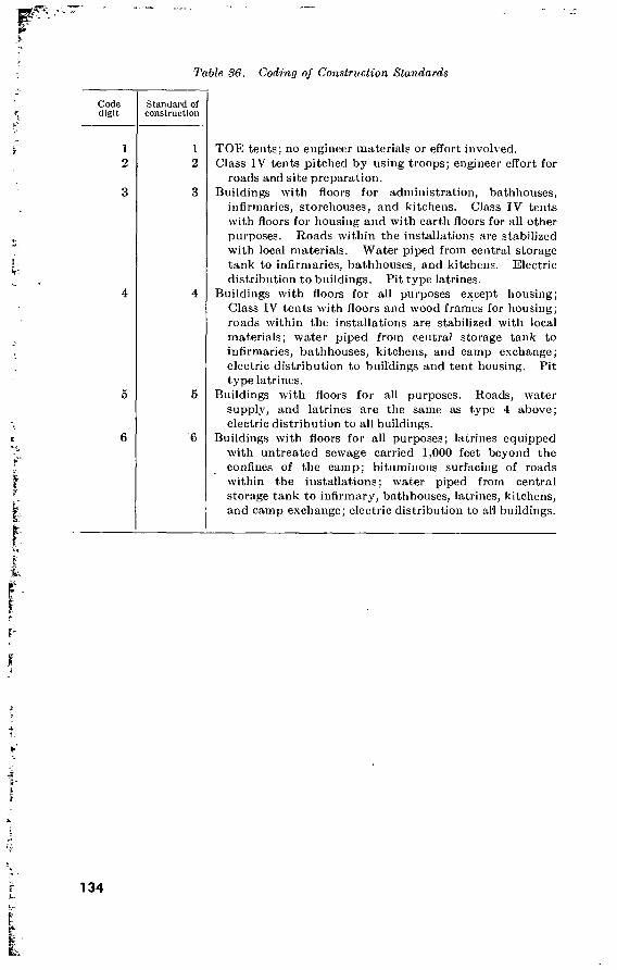
Table S6. Coding of Construction Standards
>
s it-
} ?'
I i
Code digit
Standard of construction
1 2
1 2
3 3
4 4
5 5
6 6
TOE tents; no engineer materials or effort involved. Class IV tents pitched by using troops; engineer effort for
roads and site preparation. Buildings with floors for administration, bathhouses,
infirmaries, storehouses, and kitchens. Class IV tents with floors for housing and with earth floors for all other purposes. Roads within the installations are stabilized with local materials. Water piped from central storage tank to infirmaries, bathhouses, and kitchens. Electric distribution to buildings. Pit type latrines.
Buildings with floors for all purposes except housing; Class IV tents with floors and wood frames for housing; roads within the installations are stabilized with local materials; water piped from central storage tank to infirmaries, bathhouses, kitchens, and camp exchange; electric distribution to buildings and tent housing. Pit type latrines.
Buildings with floors for all purposes. Roads, water supply, and latrines are the same as type 4 above; electric distribution to all buildings.
Buildings with floors for all purposes; latrines equipped with untreated sewage carried 1,000 feet beyond the confines of the camp; bituminous surfacing of roads within the installations; water piped from central storage tank to infirmary, bathhouses, latrines, kitchens, and camp exchange; electric distribution to ah buildings.
r
r i
-k
4 1. ¥
4
h !
I
134

CHAPTER 5
FORTIFICATIONS AND CAMOUFLAGE
Section I. GENERAL
37. General Priority of work and data on clearing, on hand excavating for earth-
works, and on minefields and barbed-wire entanglements are given in FM's 5-15, 5-34, and 101-10. Land-mine warfare is covered in FM 20-32. FM 101-10 includes estimating data for roadblocks and other antimechanized defense measures, as well as data on fordable depths of water and carrying capacity of ice. Permanent bomb- resistant structures are covered in TM 5-310. FM 5-20, 5-21, FM 5-22, and AFM 200-43 deal with camouflage.
38. Frontages Held by Units in Defense Average frontages normally assigned to infantry or engineer units
in defensive missions are given in table 37.
Table 37. Defense Frontages (in yards)
SITUATION
Branch Non-nuclear Active nuclear
Battle group. Infantrv. 2, 500-4, 500 4,000-6,000 (no mobility) ; 7,000 (calculated risk); 9,000 (motor- ized or mechanized).
ALL SITUATIONS
Bifle company
Close terrain
Open terrain
Infantry
Occupies Occupies and covers. Occupies Occupies and covers.
1 platoon
300 500 450 800
2 platoons
600 1, 000
900 1, 600
3 platoons 4 platoons
900 1, 500 1, 400 2, 400
1, 200 2, 000 1, 800 3, 000
135
Section II. COVER AND SHELTER
39. General a. Requirements. Shelters are constructed primarily to protect
troops from enemy action and the weather. They are not fighting emplacements but are often included in fighting positions. Shelters should be sited on reverse slopes, in woods, or in some form of natural defilade such as ravines, valleys, or depressions. All shelters must be camouflaged or concealed.
b. Types. Shelters are divided into two groups according to their type of construction—hasty or deliberate.
(1) Hasty shelters are normally constructed of local, expedient materials by combat troops, primarily for protection from inclement weather when on short halts and bivouacs.
(2) Deliberate shelters are constructed by supporting units in rear of frontlines for protection from artillery fire, strafing, bombing, and the weather.
(3) Shelters, whether hasty or deliberate, are further divided into three general types—
(a) Surface shelters built aboveground where ground conditions prohibit excavation.
(¿>) Cut-and-cover shelters partially or wholly dug into the ground and backfilled and covered with soil.
(c) Cave shelters dug laterally into reverse slopes or tunneled into flat ground.
40. Protection Against Conventional Weapons a. Table 38 shows the thicknesses of various materials required to
protect against single direct hits by direct-fire weapons. b. Table 39 shows the thicknesses of various materials required to
protect against projectiles and bombs exploding at a distance of 50 feet.
136
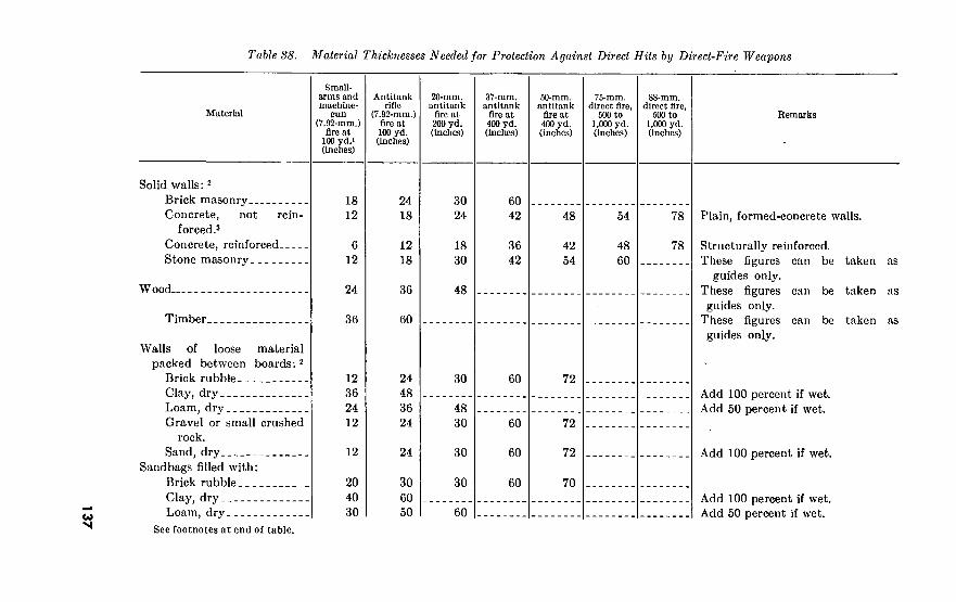
137
Table 38. Material Thicknesses Needed for Protection Against Direct Hits by Direct-Fire Weapons
Material
Solid walls:2
Brick masonry Concrete, not rein-
forced.3
Concrete, reinforced Stone masonry
W ood
Timber
Walls of loose material packed between boards: 2
Brick rubble Clay, dry Loam, dry Gravel or small crushed
rock. Sand, dry
Sandbags filled with: Brick rubble Clay, dry Loam, dry
Small- arms and machine-
gun (7.92-mm.)
fire at 100 yd.» (Inches)
Antitank rifle
(7.92-mm.) fire at 100 yd. (Inches)
20-mm. antitank
fire at 200 yd. (inches)
37-mm. antitank
fire at 400 yd. (inches)
50-mm. antitank
fire at 400 yd. (inches)
75-mm. direct fire,
500 to 1,000 yd. (Inches)
88-mm. direct fire,
500 to 1,000 yd. (inches)
Remarks
18 12
6 12
24
36
12 36 24 12
12
20 40 30
24 18
12 18
36
60
24 48 36 24
24
30 60 50
30 24
18 30
48
30
48 30
30
30
60
60 42
36 42
48
42 54
54
48 60
78
78
60 72
60
60
60
72
72
70
Plain, formed-concrete walls.
Structurally reinforced. These figures can be taken as
guides only. These figures can be taken as guides only.
These figures can be taken as guides only.
Add 100 percent if wet. Add 50 percent if wet.
Add 100 percent if wet.
Add 100 percent if wet. Add 50 percent if wet.
See footnotes at end of table.

13
8
-I "Wiw -ÏWSVIl‘,,W=!rr?V ».'•»■wr-ni*’ .. . mu»- I ■r'B. — ríT»Wjr'p^r4Mw>3i. w.-f\fTr>-v.'rrrJ'FP
‘ %, 1
Table 88. Material Thicknesses Needed for Protection Against Direct Hits by Direct-Fire Weapons—Continued
Material
Sandbags filled with—Con. Gravel or small crushed
rock. Sand, dry
Loose parapets of : 2
Clay Loam Sand
Small- arms and machine-
gun (7.92-mm.)
fire at 100 yd.« (inches)
20
20
42 36 24
Antitank rifle
(7.92-mm.) fire at 100 yd. (inches)
30
30
GO 48 36
20-rnra. antitank
fire at 200 yd. (inches)
30
30
60 48
37-ram. antitank
Are at 400 yd. (inches)
60
60
60-min. antitank
fire at 400 yd. (Inches)
70
70
75-mra. direct fire,
500 ro 1,000 yd. (inches)
88-mm. direct fire,
.500 to 1,000 yd. (inches)
Hcmarks
Add 100 percent if wet.
Add 100 percent if wet. Add 50 percent if wet. Add 100 percent if wet.
1 1 burst of 5 shots. 2 Thicknesses given to nearest half foot. 3 For 3,000 p.s.I. concrete.
Protective thicknesses given are for a single shot only (except >). Where direct-file weapons arc able to get 5 or 0 hits in the same area, the required protective thickness is approximately twice that Indicated.

Table 39. Material Thicknesses Needed for Protection Against Projectiles and Bombs Exploding 50 Feet Away
High-explosive shells and rockets General-purpose bombs
Material 75-mm. (inches)
105-mm. (Inches)
155-mm. (Inches)
100-lb. (inches)
250-lb. (inches)
500-lb. (inches)
1,000-lb. (inches)
Solid walls: Brick masonry Concrete, plain Concrete, reinforced-. Timber :
Walls of loose material tween boards:
Brick rubble Gravel, small stones.. Earth 1
Sandbags filled with: Brick rubble Gravel, small stones.. Sand 1 Earth 1
Parapets of: 2
Sand 1 Earth 1
be-
9 9
15
10 10 10 20
12 24
6 5 4
10
10 10 18
10 10 10 20
18 36
8 6 5
14
12 12 24
20 20 20 30
24 48
8 8 7
15
18 18 24
20 20 30 30
24 36
10 10 9
18
24 24 30
20 20 30 40
36 48
13 15 12 24
28 28
30 30 40 40
36 60
17 18 15 30
30 30
40 40 40 50
48
1 Figures based on dry material. If wet material, double figures. 2 Figures given to nearest >6 foot.
41. Ice and Snow: Classification
The following terms and criteria are used to describe snow con- ditions.
a. Grain Nature. (1) New snow (original crystal forms). (2) Old snow (granular).
{a) Fine-grained like table salt. (6) Coarse-grained like coarse sand.
b. Hardness. (Use mitten or glove.) (1) Soft (mitten tip or four fingers). (2) Medium bard (mitten thumb or one finger).1
(3) Hard (pencil).1
(4) Very hard (knife).1
c. Wetness. (Use mittens or gloves.) (1) Dry (snowball cannot be made). (2) Moist (does not contain water, but snowball can be made). (3) Wet (liquid water can be pressed out). (4) Slushy (mixture of snow and liquid water).
1 The object indicated (but not the foregoing one) can be pushed into the snow without considerable effort.
139

d. Surface and Pro fie Conditions. When appropriate, surface and profile conditions may be described in connection with the above classification. For example, in describing a snow profile the thickness of visually distinguishable layers and their sequence can be measured and the snow type of each layer indicated by the above classification. Drifted snow of granule form is always considered as old snow even if freshly deposited.
e. Examples. (1) New snow, dry and medium hard. (2) Fine-grained old snow, moist and hard. (3) Thirty inches of fine-grained old snow, dry and very hard,
covered by six inches of new snow, soft and dry. (4) Six-inch crust of fine-grained old snow over six inches of
drifted snow, medium hard and dry. (5) Six inches of coarse-grained old snow, soft and slushy. ,
42. Ice and Snow Cover Minimum thicknesses of snow and ice for protection against small-
arms fire are as follows: New snow, 13 feet. Tamped snow, 8 to 10 feet. Frozen snow, 6.5 feet. Ice, 3.25 feet. Ice concrete, 1 to 2 feet.
43. Ice Concrete Ice concrete is a dense frozen mixture of sand and water, or sand
with gravel and crushed rock and water. At least 10 percent of the mixture should be sand and only enough water should be added to the mixture to make it slightly liquid. A sheet of this material, 4 inches thick, will freeze solid in 4 to 6 hours at —13° F. In forti- fication construction it is used for overhead cover, parapets, breast- works, or sandbag filler.
44. Protection Against Nuclear Weapons See FM 101-31, FM 101-31A, TM 5-311, TM 23-200, DA Pam
39-1, and DA Pam 39-3.
Section III. OBSTACLES
45. Planning and Construction of Obstacles Normal obstacle planning accomplished in divisional and larger
units is summarized in table 40. Table 41 is an obstacle planning checklist for unit engineers, and table 42 shows obstacle construction data.
140

Table 40. Obstacle Planning Responsibilities
Command Pertinent points of commander’s plans
Army.
Corps.
(1) Broad barrier plan for army area, including key bands. (2) Assignment of tasks to subordinate units. Covering forces
construct covering barriers, and security forces on open flanks erect flank barriers. Army and corps troops install rear-area and flank barriers.
(3) Limitations on use of obstacles in any particular area to insure coordination with general plans.
(4) Emphasis on need for secrecy. Precautions must be taken to safeguard charts and maintain security of barrier plan. Broad plan should not go below division.
(1) Detailed barrier plan for corps area, made from map study, covering:
(o) Location of natural and artificial barriers, including major minefields;
(6) Location of lanes to be left open for counter-attack plans and supply.
(2) Assignment of tasks to subordinate units including division and corps troops.
(3) Close coordination of division plans. (4) Detailed siting of corps flank barriers. (5) Maps or overlays showing plan in enough detail so lower
units will know exactly which barrier lines are to be in- stalled or reinforced.
Division. Based on corps master plan: (1) Plan of bands or zones of obstacles and purpose each is to
serve. (2) Timetable and priority of construction. (3) Demolition orders. (4) Routes to be kept open in accordance with tactical plan. (5) Need for secrecy. Detailed plan should not be in hands of
front-line units. (6) Limitations on use of chemical agents. (7) Assignment of troops and equipment for construction and
defense.
141
142
/T1-'' '. I \''.r f. ' ’’ -i I I ' 7 "VH TT- r T-’r-- ^
t.i *• ■.•at-a)! ••-.
Table il. Engineer Obstacle Planning
Plan phases Phase details Source ut Information
Map study . (1) Analyze all natural obstacles useful to mission of unit- (2) Locate gaps and defiles in natural obstacles.
Maps, aerial photographs.
Reconnaissance. (1) Locate individual obstacles from actual reconnaissance of terrain and determine effectiveness of each obstacle.
(2) Determine type of artificial obstacle to use at each location or amount of work necessary to reinforce natural obstacle.
(3) Estimate time, labor, and materials needed for each obstacle.
Engineer reconnaissance patrols, per- sonal reconnaissance, combat patrols, and civilians.
General plans. (1) Indicate plan on map in graphic form showing location of each obstacle band and principal types of obstacles in band.
(2) Prepare table of priority of construction, including time, labor, and material estimates.
(3) Submit final plan for approval and coordination with tactical plan of unit commander.
Previous reconnaissance and map study, and orders from higher authorities.
Detailed plans-
Report-
(1) Prepare detailed plans and orders (2) Subdivide work, assign tasks to units, and issue orders.
Previous reconnaissance and map study.
Submit report of completed obstacles to next higher commander.

533500
o o
o
bJ
Table 42. Obstacle Construction Data
Obstacle Construction method
Antitank ditch By multiple-charge method— 10 ft. deep 30 ft. wide
By hand tools— 6 ft. deep.,. 12 ft. wide..
Normal employment
(1) For permanent system of fortifications:
Construct across wide avenues of approach.
(2) For hasty or temporary fortifications. Construct across only short dis- tances—25 to 50 ft.
Using jli-yd. shovel with 2 oper- ators and 3 to 10 finishers.
Log post obstacle
Contamination by per- sistent chemicals (when authorized).
Substantial posts set In the ground, density of 1 post per linear foot, 2)4- to 3)4-ft. projection.
Contaminate artificial obstacles 1 to impede removal. Contami- nate roads and areas as part of a barrier mission.
or more chemical mines per ob- stacle. 200 mines per mile of road, or—Airplane spray : Average area covered by 1 airplane—
80 yd. long 300 yd. wide
Construction rate
1 squad with power earth auger and demolition equipment can complete 100 yds. in 12 hr.
One platoon under average con- ditions can do 100 ft. of tri- angular ditch iu 7)4 hr., and 100 ft. of trapezoidal ditch in 1-1 hr.
Platoon can dig 100 ft. of tri- angular ditch in 4)4 hr. and 100 ft. of trapezoidal ditch in 9 hr.
1 squad with pile driver can complete 50 ft. in 1 day under average conditions.
1 squad can contaminate 1 mile of road in 1)4 hr.

46. Minefields a. The various types of minefields are as follows:
(1) Protective minefields, used for the close-in protection of small units in forward combat areas and units or installations in rear areas if infiltration, raiding, or sabotage is a threat.
(2) Defensive minefields, used as an element in the defense of organized and occupied tactical localities within a battle position.
(3) Barrier minefields, used to block an enemy attack in certain areas and to canalize his advance into other selected areas.
(4) Nuisance minefields, used to delay and disorganize the enemy and hinder his use of a certain area or route.
(5) Phony minefields, used to make the enemy think that an area has been mined.
h. Logistical data on antitank and antipersonnel mines are shown in table 43. Table 44 shows data on minefield clearing with explosive devices. The weights and explosive contents of certain American and foreign mines are given in paragraph 210. For further details, see FM 5-25, FM 20-32, and TM 9-1946.
144

145
Tabic 48- Logistical Mine Data Table
Note. Figures in parentheses indicate maximum load w/in 100 percent overhead capability &/or maximum volume of cargo space
Mine model & typo
M-7 AV.
M-6 AT.
M-15-
Welght (lb.) per
miuc
5. 0
20. 0
30. 0
Mine packaging data
-Yumber of mines, etc., per crate
a. 8, w/fuzes.
b. 12, w/fuzes...
a. uncrated mines.
b. 1, w/fuze & activ.
c. 2, w/fuzes & activ.
a. uncrated mines.
b. 1, w/fuze & activ.
Wt (lb.) poi crate
56
71. 5
Craft dimensions (in.)
Length
19. 25
23. 5
13.13 in. diam.
31
00
49
13. 5
18. 13
Width
11
11. 75
13. 5
16
13.13 in. diam.
18 15. 13
Height
8. 25
9. 5
3. 25
3. 75
9. 75
7. 5
Capacity of indicated army vehicles
M-35 Z'/î-ton cargo truck (cargo space: 147 by 88 by CO in.)
Number of crates
90 (178)
70 (140)
162 (322)
84 (160)
103 (200)
How carried
Flat.
Flat.
Flat.
On end (Hat) .
Flat.
Flat (flat, 11 on end).
Flat.
Number of types of crates
2
(4)
2 (4)
1
(6)
2 (4) ■
3- (3)'
3 (5)
Total num bur raines
720 (1, 424)
840 (1, 680)
250 (204)
162 (322)
168 (320)
166 (209)
103 (200)
Total weight (tons)
2. 52 (4. 98)
2. 5 (5)
2. 5 (2. 64)
2. 51 (4. 99)
2. 52 (4.8)
2. 49 (3. 13)
2. 53 (4. 9)
14
6
Table 48. Logistical Mine Data Table—Continued
Mine model* type
M-19 AT.
T29 AT.
M-2 AP.
M-3 AP.
M-16 AP.
M-18 AP.
Weight (lb.) per
mine
28. 0
15. 0
5. 0
9. 6
8. 0
2. 5
Mine packaging data
Number of mines, etc.,
2, w/fuzes & activ.
2, w/T-1200 fuzes.
6, w/fuzes &
6, w/fuzes &
4, w/fuzes & wire.
a. 6(M-68 Kit).
b. 10 (M-69 Kit).
Wt (lb.) per crate
80
50. 3
50
72
45
33. 1
45
Craft dimensions (In.)
Length
16. 25
26. 5
15
18
15. 75
20
14. 25
Width
10. 5
11
10. 25
8. 75
10. 13
11. 5
15
Height
16
7. 33
9. 5
9. 5
8. 5
9. 75
17. 25
Capacity of Indicated army vehicles
M-35 2^-ton cargo truck (cargo space: 147 by 88 by 60 In.)
Number of crates
63 (125)
100 (198)
100 (200)
70 (138)
112 (222)
151 (294)
112 (162)
How carried
On end (on side)
On end (flat).
Flat.
Flat.
Flat.
Flat.
Flat.
Number of types of crates
1 (3)
1
(5)
2 (3)
2-
(2+)
2 (4)
4 (6)
2 + (3)
Total num- ber mines
126 (250)
200 (396)
600 (1,200)
420 (828)
448 (888)
905 (1, 764)
1, 120 (1, 620)
Total weight (tons)
2. 52 (5)
2. 51 (4. 97)
2. 5 (5)
2. 52 (4. 96)
2. 52 (4. 99)
2. 49 (4. 87)
2. 52 (3. 64)

14
7
M-14 AP.
E-5 ehern.
M-48 Para- chute Flare.
M-49 Static Flare.
0. 2
24. 7
5. 0
1. 4
90, w/dets. & Wrenches.
3, w/fuzes & activ.
4, w/fuzes & wire.
a. 16, w/fuzes & wire.
b. 25, w/fuzes &
44
a. 110 (1
drum)
b. 1,840 (pal- let of 16 drums)
41. 0
44. 9
59
19 18
17.5 in. diam. (standard shipping drum).
52
14. 7
21. 25
21. 25
46
13. 13
14. 5
14. 5
8. 75
22
48
11
11
11
114 (227)
46 (80)
3 pal- lets.
122 (244)
111
(180)
84 (170)
Flat (on end).
On side (on end).
Flat.
Flat.
Flat.
Flat.
2 (2)
2 + (4 + )
3 + (5)
3- (5)
10, 260 (20, 430)
138 (240)
144
488 (976)
1, 776 (2, 880)
2, 100 (4, 250)
2. 5 (4. 99)
2. 53 (4. 4)
2. 76
2. 5 (5)
2. 49 (4. 04)
2. 47 (5)

T 48
Table 43. Logistical Mine Data Table—Continued
Mine model & type
M-7 AV.
M-6 AT.
M-15.
M-19 AT.
T29 AT.
M-105 I'/j-ton trailer (cargo space: 133 by 87 by 71 in.)
Number of crates
56 (HO)
41 (85)
96 (195)
50 (100)
51 (122)
How carried
Flat.
Number of tiers of crates
Total num- ber of mines
2 (3)
Flat (on end) —
Flat (on edge)..:
Flat.
Flat.
Flat (on edge).
Flat.
37 (75)
59 (119)
Flat.
2
(1)
3 (2)
2 (4)
2 (4-)
3 (2)
Flat. 2 (4-)
448 (880)
492 (1,020)
Total weight (tons)
1. 56 (3. 08)
1. 46 (3. 02)
150 (300)
96 . (195)
100 (200)
100 (200)
61 (122)
74 (150)
118 (238)
1. 5 (3)
1. 48 (3. 02)
M-47 2Vä-ton dump truck (cargo space: 108 by 70 by IS in.) (Volume is determining factor)
Determine number of crates
72.
63.
140.
1. 5 (3)
1. 5 (3)
1. 49 (2. 98)
1. 48 (3)
1. 49 (2. 99)
42.
56.
40.
81.
Capacity how carried
On end.
On end.
On edge.
On end.
On end.
On edge (or flat).
On end.
On end.
On end.
Number of tiers of crates
1
(3)
Total num- ber mines
576
756
165
140
84
105
56
80
162
Total weight (tons)
2. 01
2. 25
1. 65
2. 17
1. 26
1. 57
1. 37
1. 6
2. 03

149
M-2 AP_
M-3 AP_
M-1G AP.
M-18 AP_
M-14 AP_
E-5 chem.
M-48 Parachute Flare.
M-49 Static Flare.
GO (120)
41 (83)
6Ü
(133)
00 (181)
6G (133)
.68 (136)
27 (54)
2 pal- lets.
73 ( 146)
66 (132)
50 (101)
Flat.
Flat.
Flat.
Flat.
Flat.
Flat.
Flat.
Flat.
Flat.
Flat.
Flat.
1 (2)
1 (2-)
1- (2 + )
3- (5)
2
(3)
3 (5)
2-
(3)
2 + (3-1
2 (4-)
2 (3-)
360 (740)
216 (408)
264 (532)
540 (I, 086)
660 (I, 330)
6, 120 (12, 240)
71 ( 142)
96
292 (584)
1, 056 (2, 112)
1,250 (2, 525)
1. £ (3)
1. 47 (2. 98)
1. 48 (2. 90)
1. 48 (2. 99)
1. 48 (2. 99)
1. 40 (2. 90)
1. 48 (2. 97)
1. 84
1. 40 (2. 98)
1. 48 (2. 96)
1. 47 (2. 97)
70-
70-
80-
63.
28.
48.
24.
2 pallets
70.
42.
42.
On end (or flat).
On end (or flat).
On end (or flat).
On end.
Flat.
On eud-
On end_
Flat-
Flat.
On end.
On end.
1 (2)
1 — (2-)
1 (2)
420
420
320
378
280
4, 320
72
96
280
672
1. 050
1. 75
2. 52
1. 80
1. 04
. 48
1. 05
1. 32
1. 84
1. 43
. 94
1. 23
-, ',T ’ri ‘s • -i .f ^
Ta6Ze Clearing and Breaching Minefields with Explosive Devices
Item M3A1 Cable, detonating, mine-clearing, AP, M 1
Bangalore torpedo
Purpose .
Length Weight Weight of explosive Metal used in case Crater produced:
Length Width Depth
Usual width of mine clearance accomplished.
Breach AT minefield.
400 ft 9,000 lb 4,480 lb Aluminum
320 ft 4-12 ft. or more. 2-4 ft. or more.. 10-15 ft
Clear narrow lane in AP mine- field.
170 ft 63 lb 46 lb Aluminum
(2)-
8 ft. or less <
0).
50 ft. 168 lb. 85 lb. Aluminum.
56 ft. (3).
(3). 10 ft. or less.1
1 The primary purpose of the bangalore torpedo is to clear a path through wire, will destroy or detonate most AP and AT mines within 5 ft. of it.
2 No clearly defined crater. Surface soil disturbed.
3 Shallow. < Mines directly under the cable will be destroyed or detonated. Pressure-type mines
within ö ft. of it may or may not be detonated.
47. Wire Entanglements Quantities and estimating data for barbed-wire obstacles are given in FM 101-10 and FM 5-34. Fundamental
principles used in locating them are summarized in table 45. Table 46 shows quantities and truckloads required per thousand yards of the various barbed-wire entanglements.

151 Table 45- Barbed-Wire Enlarujlemciil Principles
Type according to mission
Location Depth Siting requirements Gaps
Tactical Along friendly side of final protective line. Extend across front of a position but are not necessarily continuous.
Protective Close enough to defense area for day and night observa- tion and far enough away to keep enemy beyond nor- mal hand grenade range.
1 belt mini- mum.
(1) Covered by fire. (2) Under observation and
protected by antiperson- nel mines and warning devices.'
(3) Avoid regular geometric layouts and easily dis- closed positions.
(4) Concealed from ground and air observation wherever possible by in- corporation of natural features such as hedges, woods,. paths, or fence lines.
(5) Coordinated with other elements of the defense.
(6) Use in sufficient quantity.
Leave gaps during erection to:
(1) Provide passage for patrols or working parties.
(2) Permit advance of attacking or coun- terattacking ele- ments.
Supplementary In regulär lines in front of tactical wire and between mor.tar target areas; and to connect platoon and company defense areas.
1 belt Added when tiriie permits, to con- ceal exact location and direction of tactical wire.
1 When practicable and if authorized by the commander of a division or larger unit.
"V J." '' 1 ■* ' > 'r 1 i i'- L A.

Table 46. Mrire Loads
Type Tons Measure-
ment tons 1
Truckloads
%-ton 2!4-ton
Double apron, 4 and 2 pace Double apron, 6 and 3 pace High wire (less guy wires) Low wire, 4 and 2 pace 4-strand fence Double-belt expedient concertina Triple-belt expedient concertina (pyramided). Triple-belt standard Dannert concertina
5 3. 5 6 3. 75 2 7
10. 5 7. 5
6. 4 4. 5
' 7. 6 4. 75 2. 54 8. 9
13. 4 9. 5
7 5 8 5 3
10
14 10
i Measurement ton 40 cubic feet.
Section IV. CAMOUFLAGE
48. Issue Camouflage Materials Issue camouflage materials include cotton twine nets, both
ungarnished and garnished with vegetable fiber burlap in flat-top or drape patterns; camouflage net sets of the drape type comprised of two or more garnished nets with ancillary components; wire netting which can be garnished with vegetable fiber, steel wool, paints, wire, wire rope, cotton twine, fiber rope, wood and metal stakes and sup- ports; and several miscellaneous items.
49. Nets and Net Sets a. Individual nets arc issued ungarnished or garnished with vege-
table fiber (burlap) in flat-top pattern or in drape pattern. (1) Flattops. A flattop consists of a twine net (wire for more
permanent installations) that is stretched parallel with the ground and garnished with natural on artificial materials to blend with the surrounding terrain. A flattop should extend past the area to be concealed on each side by a distance equal to twice the height of the flattop above the ground. For complete concealment flattops should be no more than three feet above the general height of the vegetation at their edges.
(2) Drape nets. Drape nets (individual) are pregarnished twine nets, designed to provide concealment for vehicles, artillery, and other similar equipment. They are issued in the following sizes (in feet) : 17 by 35 29 by 29 22 by 22 36 by 44 29 by 14 45 by 45
152

Table 4-7■ Characteristics of Camouflage Net Sets, Drape Type
Net sot, drupe Size and number of nets Total square feet
Weight (pounds)
Cubage (feet) Packaging
72' by 88' 58' by 58' 44' by 44' 34' by 35' 28' by 29' 90' by 90' (Basic set).
90'
36' by 44' (4).. 29' by 29' (4).. 22' by 22' (4).. 17' by 35' (2).. 14' by 29' (2).. 45' by 45'' (4).
With supplemental equip- ment 104' by 118'.
by 180'
14' by 29' (12); 29' by 29' (2).
45' by 45' (8)
6, 336 3, 364 1, 936 1, 190
812 8, 100
12, 272
10, 200
1, 070. 0 648. 0 305. 5 300. 0 145. 0
1, 320. 0
1, 713. 0
2, 483. 0
00. 5 34. 0 21. 5 15. 0
6. 0 79. 0
111. 3
151. 0
5 bags; 3 pole-carrying boxes. 3 bags; 2 pole-carrying boxes. 3 bags; 1 pole-carrying box. 2 bags; 1 pole-carrying box. 1 bag (nets). Ribs (loose). 5 bags; 2 pole-carrying boxes;
3 heavy-duty pole-carrying cases.
3 bags.
2 pole-carrying boxes; 8 pole- carrying cases; 10 canvas car- rying bags.

b. Camouflage nets garnished in drape pattern are also issued in sets. These sets contain two or more nets for assembly, garnished as a component to fit into the overall pattern of the set. Since these nets drape to the ground, they offer considerably better concealment than do the nets of the flattop pattern. Their principal character- istics are shown in table 47.
50. Garnishing Nets in the Field a. Precolored cloth or cloth impregnated in the field is used to
match garnished nets to local coloration. Percentages of colors usually required are shown in table 48.
Table 48. Color Percentages
Tropical and summer temperate
Winter temperate Desert terrain All seasonal
Dark green, 70 per- cent.
Light green, 15 per- cent.
Field drab, 15 per- cent.
Earth brown, 60 percent.
Olive drab, 30 percent.
Earth red, 10 percent.
Sand, 80 percent
Olive drab, 10 percent.
Light green, 10 percent.
Dark green, 60 percent.
Earth brown, 40 percent.
b. Materials and man-hours for garnishing twine net, -mesh 2/4
inches square, are shown in table 49.
154

Table JfO. Camouflage Materials and Man-Hours Required for Garnishing Twine Net
Size (feet)
Weight (pounds)
Flattop Drape
Cubage (cubic feet)
Flattop Drape
Number of garnishing strips 2" by 60''
Flattop Drape
Number of rolls 2'' by 300'
Flattop Drape
Approximate man-hours
Flattop Drape
15 by 15. 14 by 29. 22 by 22. 17 by 35. 29 by 29. 36 by 44. 45 by 45.
9 12 15 20 27 51 60
11. 8 15. 8 19. 6 26. 2 35. 2 66. 9 78. 5
0. 9 1. 0 1. 5 2. 0 3. 3 5. 0 6. 0
1. 18 1. 31 1. 96 2. 6 4. 3 6. 6 7. 9
234. 0 422. 0 454. 0 017. 0 874. 6
1, 645. 0 2, 110. 0
306 550 594 808
1, 142 2, 160 2, 760
4 7 8
10 14-15
27 35
5 9-10 9-10
13-14 19 36 46
5 14
14-15 19 30 55 60
7-8 19-20
19 25-26
40 60
62-63
51. Paints and Adhesives
Basic data for various types of paints and adhesives used for camouflage purposes are given in table 50 and stains used in the field are given in table 50.1. Supplementing this, table 51 gives data on tone-down materials for use on concrete, and table 52 gives data on adhesives used with granules. Table 52.1 gives the coverage data of paints and adhesives on certain types of materials. For further details see FM 5-22.
15
6
W^f7' lî-^yr-.t ' • >•,. Y / F, ;i», ^»rrr-r- -r---, -, , , ^
-"ti^’s; m -^T rmm
Table 50. Camouflage Paints and Adhesives
Type of material
Paint, camouflage, resin oil emulsion and resin emulsion type paste.
Paint, camouflage, emul- sifiable.
Paint, protein-binder, cold water.
Paint, paste, lusterless, gasoline removable.
Cement water paints-
Oil-type paints for run- ways.
Paint, camouflage, bitu- minous emulsion, ad- hesive.
How issued
Ready-mixed
Paste-
Powder-
Paste.
Powder, cement; protein powder, modified ce- ment; and oil paste, modified cement.
Ready-mixed
Ready-mixed.
Colors
FED SPEC TT- C-295.
Standard camou- flage colors.
FED SPEC TT-C-295.
White, in engr. depots; com- mercial, all colors.
A range of light colors.
White and yellow.
Dries to a black- ish brown.
How prepared
Mix with water or min- eral spirits.
Mix with water or - organic solvents.
Mix with water
Mix with gasoline or mineral spirits.
Mix with water.
Drying time
Ready for application; can thin with mineral spirits or turpentine.
Mixed with water. For better penetration, add wetting agent.
About 24 hours..
On wood or metal, not over 6 hours.
48 hours to be slightly rain resistant; can handle in 6 hours.
15 to 60 min- utes.
30 minutes to 6 hours.
Less than 1 hour.
To touch, 8 hours.
Resultant surface
Flat finish.
Flat and luster- less.
Hard, flat surface.
Flat.
Hard, opaque, flat, luster- less.
Flat (must be ^specified).
Medium gloss; dulls rapidly on exposure.

157 Cutback asphalt
Primer, enamel under- coater, phenolic.
Camouflage face paint
Stains for wood surfaces..
Field-expedient tentage stain No. 1.
Field-expedient tentage stain No. 2.
Fabric dye
Paint, emulsified, field expedient.
Slow cure, me- dium cure, rapid cure.
Ready-mixed..
Stick form
3 types, all ready- mixed.
Field expedient
Field expedient
Both liquid and powder.
Field expedient
Dark brown to black.
Dull red, yellow
White troops, light green and loam. Colored, light green and sand.
Varies with man- ufacturer.
Dark gray
Dark gray
Various
Depends on range of earth colors available.
Slow cure, diesel oil; inedium cure, kero- sene; rapid cure, gaso- line.
Stil' with paddle
Variable, but quick dry- ¡ ing- ;
Enough to re- coat, 24 hours.
Ready for use I,
Ready for use; can thin with mineral spirits or turpentine.
Mix with earth, GI or field expedient soap, soot, and paraffin, as directed.
Mix with charcoal and water as directed.
Mix with salt and water and use as directed.
Mix, as directed, crank- case oil salvage or waste, water, and pig- mented soil with: (Type I) ground clay or powdered carbon and gasoline; or (Type II) GI or field expe- dient soap and clay or diatomaceous earth.
S-12 hours.
Variable, fairly rapid.
At least 2 hours.
Mat.
Dull, opaque film.
Flat.
Flat, lusterless.
Mat finish.

15
8
Table 50. Camouflage Paints Adhesives—Continued
Type of material How Issued Colors How prepared Drying time Resultant surface
Field expedient soap (for field expedient paint).
Field expedient.
Raw molasses (for field Liquid. expedient paint).
Used crankcase oil Salvage
Brown
Brownish.
Mix and treat, as directed, waste kitchen grease and wood ashes.
Thin with water Always sticky...
Use as supplied or mix with native colored earths.
Asphalt cement Canvas refinishing com-
pound.
Commercial.. Ready-mixed Dark O.D., O.D.,
or green. Major unit commanders may requisition other colors.
Stir; dilute with gasoline if needed.
At least 2 hours. Mat finish.
Field expedient green vegetation adhesive.
Field expedient starch adhesive.
Glue-paste adhesive
Practically any green vegeta- tion.
Any food con- taining starch, such as flour, grains, pota- toes, etc.
Field expedient..
Boil fresh-cut plant material in water and treat as directed.
Prepare from raw materials as directed.
Combine, as directed, flour paste, glue siz- ing, resin-sizing, var nish, borax, and hot water.

53
35
06
Table 50.1. Field Expedient Stains
a .o
Ui >0
Type Color Source Use How prepared Application Drying time
Finish Removal Climate limitations
Tent Stain #1.
Dark Manufac- ' gray. ture by
troops.
Tent Stain #2.
Dark Manufac- gray. ture by
troops.
Used crank- case oil.
Brown. Motor pools, air bases.
Asphalt cement.
N/A__ Com- mercial.
Tentage Mix y2 lb soap with 8 gals water. Add
Faded or undyed tents.
To tone down concrete, stabilized soil, soil around emplace- ments.
Staining concrete or bitu- minous surface.
enough paraffin soaked soot to get the desired color.
Mix char- coal with water to
■ desired shade.
Ready for applica- tion.
Ready mixed.
Brushing, Swabbing.
Rapid. Flat Not prac- tical.
Not recom- mended for freez- ing tem- pera- tures.
Swabbing..
Spreading..
Rapid.". Flat Not prac- tical.
N/A-. N/A-. N/A
Not recom- mended for freez- ing tem- peratures.
None
Brushing, Pressure distribu- tor.
30 min- utes.
Rough. N/A 45° F. lim- it for ap- plication.'
Durability
Fair.
Good-
Fair.
Good.

16
0
Table öl. Tune-down Materials For Use on Concrete
Coating material Container Colors Source Durability Preparation Drying time (hours)
Climate limita- tions
Application
Cutback as- phalt (coal tar may be substituted).
55 gal. drums.
Brownish- black.
Commercial,1
Fed. Spec. SS-A671.
Good- Ready mixed : quick-dry, medium- dry, slow- dry.
(Med) 24
Requires dry surface and conditions. May be used at subfreezing temp.
Brushing; spray- ing—hand or pres- sure.
Coating com- pound, bitu- minous emulsion
55 gal. drums.
Brownish- black.
Commercial, MIL-P- 3840.
Good. Ready mixed _. 48 Can be ap- plied to damp sur- face. Tem- perature must be above 45° F. Not good in tropics.
Brushing; > pressure spraying.
Paint, water, paste.
5 gal. can.
All camou- flage col- ors.
Commer- cial,1 MIL- P-13340.
Fair. Must be thinned w/gasoline or water, 1 to 1 by volume. Use gas or naphtha be- low freezing.
Can be ap- plied to damp sur- face. Good between — 40° and + 160° F.
Brushing; pressure spraying.

161 Pigmented so-
dium sili- cate.
Varies All camou- flage col- ors.
Commer- cial.1
Good on rough sur- face, poor on smooth.
Concentrate thinned w/water is sprayed on surface fol- lowed by spraying with cal- cium chlo- ride to set or fix.
N/A Can be ap- plied to damp sur- face.
Pressure spraying.
Paint, traffic_ . 1 gal. cans.
White. TT-P-115A. Excellent for traffic sur- face.
Ready mixed. Dry, clean surface re- quired.
Pressure spraying.
Xylene and tar (Rt. 2). Kerosene and asphalt (similar to British pitch and creosote mix).
Varies Brownish- black.
Commer- cial.1
Fair. Mix 80 tar to 0.20 xy- lene. Mix 25 asphalt to 75 kero- sene by volume.
Rapid Dry, clean surface re- quired.
Spraying— hand and pressure.
1 Material has no specification, Is made up in camouflage colors commercially.
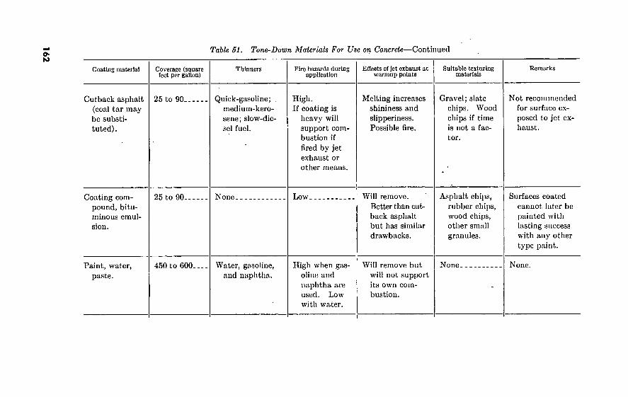
162
Coating material
Cutback asphalt (coal tar may be substi- tuted).
Coating com- pound, bitu- minous emul- sion.
Paint, water, paste.
Table 51. Tone-Down Materials For Use on Concrete—Continued
Coverage (square feet per gallon)
Thlnners Fire hazards during application
Effects of jot exhaust at warmup points
Suitable texturing materials
Remarks
25 to 90. Quick-gasoline; . medium-kero- sene; slow-die- sel fuel.
High. If coating is
heavy will support com- bustion if fired by jet exhaust or other means.
Melting increases shininess and slipperiness. Possible fire.
Gravel ; slate chips. Wood chips if time is not a fac- tor.
Not recommended for surface ex- posed to jet ex- haust.
25 to 90. None Low Will remove. Better than cut- back asphalt but has similar drawbacks.
Asphalt chips, rubber chips, wood chips, other small granules.
Surfaces coated cannot later be painted with lasting success with any other type paint.
450 to 600 Water, gasoline, and naphtha.
High when gas- oline and naphtha are used. Low with water.
Will remove but will not support its own com- bustion.
None None.

-T63
Pigmented so- dium silicate.
Paint, traffic.
Xylene and tar (Ht. 2). Kerosene and asphalt (simi- lar to British pitch and cre- osote mix).
Not available.
300 to 350.
Not available.
Water.
Turpentine, gaso- lene, naphtha.
Xylene, kerosene..
None.
Medium to high.
High.
Not available.
Will blister and change color.
Will remove. No fire hazard with thin film, may be with thick film.
None.
None.
None.
Good for limited types of surface. Traffic on smooth surface pulverizes brit- tle coating which then blows away or wishes off.
Best but costly.
Primarily a cheap stain. Has ap- plication and fire drawbacks.

Table 52. Texturing Materials
Texturing materials Durability compared with rock
chips (percent)
Abrasion Coverage per ton in
square yards
Sources
Wood chips -
Rock chips J4"-
Gravel Leather chips..
Cofifee beans. Wood cubes..
Fabric (burlap scraps or similar ma- terials) .
Plant mix, 1)4" open graded aggregate.
Slag
Pine bough tips Pine cones Excelsior Shredded coconut
fiber (coir). Redwood fiber Cinders
Feathers.
Cottonseed hulls. Spanish moss Paper, shredded.
Sawdust,
Tin cans Leaves and chopped
palm fronds. Seaweed
75
100
100 75
75 60
30
100
80
20 20 30 15
30 90
15
50 10
. 05
75
' Low.
High.
Medium. Low
Low. Low.
Low.
Medium..
High.
Low. Low. Low. Low.
Low. High.
Low.
Low. Low. Low.
Low.
15
10
Low.
Low.
800
90
90 115
90 161
2, 000
22
90
400 161
2, 000 2, 000
1, 600 90
20, 000
3, 000 2, 000 2, 000
3, 000
2, 000
2, 000
Tanneries, wood pulp concerns, paper mills.
Quarries and road building contractors.
Gravel pits. Shoe and leather
goods manufac- turers.
Coffee growers. Lumber (cubes made
on site). Rag and textile con-
cerns.
Asphalt distributors.
Iron and steel blast furnaces.
Local labor. Local labor. Wood-pulp concerns. Byproduct of cocoa
manufacturing.
RR. roundhouses, boilers, factories.
Poultry slaughter- houses, mattress manufacturers.
Cotton gins. Local labor. Paper mills, junk
dealers. Lumber mills, furni-
ture manufacturers, plywood mills.
Salvage depots. Local labor.
Local labor.
Note. These figures are approximate, for purpose of comparison and rough estimates.
164

165
Table 52.1. Coverage Dala
Coating material
Paint, water, paste MIL-P-13340 (table I)
Asphalt, macadam, bituminous surfaces, tar-coatcd roofing paper
Brushing
Square feet per gallon
450
Man- hours
per 100 square
feet
Spraying
Square feet per gallon
600
Sprayer (square feet per hour)
3,000
Pressure distrib-
utor (square feet per minute)
N/A
Concrete, stucco, brick, building stone, slate
Brushing
Square feet per gallon
400
Man-hours per 100
square feet
Spraying
Square feet per gallon
500
Sprayer (square feet per hour)
3, 000
Pressure distributor
(square feet per minute)
N/A
Xylene and tar (R-2); kerosene and asphalt (table II) 200 200 2, 040 6, 000
Paint, temporary, paste, MIL- P-13983 (table I)
Cutback asphalt types I, II, III (table I) Fed. SSA-671
1 100 i 1 100 2,000 30 1. 66 30 900 2,400
: 30 2. 15 2 30 2 900
1 8,000
2 2, 400
Used crankcase oil (table III). 50 50 1, 500 4, 000
Stains, table I-
Coating compound, bituminous emulsion MIL-P-3840 (table
«- 45 1. 1 45 1,350 3,600 45 1. 1 45 1, 350 3, 600
Asphalt cement (table III). 50 50 N/A 4,000 50 . 2 50 N/A 4, 000
Water, paint, paste MIL-P- 18358 (table I)
See footnotes at end of table.

166
yHjyyevwyiyevv- -rrur-r 'v"rw.çr'-^»"'T v'’v ^^r-:: '• •»’-K - - - -i . ■ ' >*’ • Sfr’'’^''•’-J**«y*?lß!'T’* J - ■ ' f»‘ VT?
Table 52J. Coverage Data—Continued
Coating material
Glass
Brushing
Square feet per gallon
Man-hours per 100 sq. ft.
Spraying
Square feet per gallon
Square feet per
hour
Coated or primed metal
Brushing
Square feet per gallon
Man-hours per 100 sq. ft.
Spraying
Square feet per gallon
Square feet per
hour
Galvanized Metal
Brushing
Square feet per gallon
Man-hours per 100 sq. ft.
Spraying
Square feet per gallon
Square feet per
hour
Paint, water, paste MIL-P- 13340 (table I) 600 750 3, 000 600 750 3, 000 600 750 3, 000
Xylene and tar (R-2) ; kerosene and asphalt (table II)
Paint, temporary, paste MIL-P- 13983 (table I) 500 600 3, 000 500 600 3, 000
Cutback asphalt types I, II, III (table I) Fed. SSA-671 30 1. 66 30 900 30 1. 66 30 900 30 1. 66 30 900
Used crankcase oil (table III).
Stains, table I-
Coating compound, bituminous emulsion MIL-P-3840 (table I) 45 1. 1 45 1,350 45 1. 1 45 900 45 1. 1 45 1, 350
Asphalt cement (table III) -
Water, paint, paste MIL-P- 18358 (table I).. 500 600 3, 000 500 600 3, 000

167
Table 62.1. Coverage Data—Continued
Coating material
Paint, water, paste MIL-P- 13340 (table I)
Mineral-coated roofing
Brushing
Square feet per gallon
450
Man-hours per 100 sq. ft.
Spraying
Square feet per gallon
600
Square feet per
hour
3, 000
Rubber
Brushing
Square feet per gallon
450
Man-hours per 100 sq. ft.
Spraying
Square feet per gallon
600
Square feet per
hour
3, 000
Wood
Brushing
Square feet per gallon
450
Man-hours per 100 sq. ft.
Spraying
Square feet per gallon
600
Square feet per
hour
3, 000
Xylene and tar (R-2) ; kerosene and asphalt (table II)
Paint, temporary, paste, MIL- P-13983 (table I)
Cutback asphalt types I, II, III (table I) Fed. SSA-671 30 1. 66 30 900 30 1. 66 30 900
Used crankcase oil (table III).
Stains, table I. 200 200 3, 000
Coating compound, bituminous emulsion MIL-P-3840 (table I) 45 1. 1 45 1, 350 45 1. 1
Asphalt cement (table III).
45 1, 350
Water, paint, paste MIL-P- 18358 (table I) 400 475 2, 850 400 475 2, 850

16
8
*^H. > ^ ; f',?r'nir”r^cf^?ç,rv-i^1
Table 52.1. Coverage Data—Continued
Coating material
Grass
Spraying
Square feet per gallon
Sprayer (square feet
per hour)
Pressure distributor
(square feet)
Earth, sand, and stabilized soil
Spraying
Square feet per gallon
Sprayer (square feet
per hour)
Pressure distributor
(square feet)
Glass fiber and steel wool
Spraying
Square feet per gallon
Sprayer (square feet
per hour)
Feather-garnished and mineral-fiber-garnislicd-
netting
Spraying
Square feet per gallon
Sprayer (square feet
per hour)
Paint, water, paste MIL-P-13340 (table I) 600 3, 000 600 6, 000
Xylene and tar (R-2) ; keorsene and asphalt (table II)
Paint, temporary, paste, MIL-P- 13983 (table I)
Cutback asphalt types I, II, III (table I) Fed. SSA-671 100 2, 000 8, 000 100 2, 000 8, 000
Used crankcase oil (table III). 20 60 1, 600
Stains, table I.
Coating compound, bituminous emul- sion MIL-P-3840 (table I) 100 2, 000 8, 000 100 2, 000 8, 000
Asphalt cement (table III)_
Water, paint, paste MIL-P-18358 (table I) 350 ' 5, 250
1 Cutback asphalt types II and III only. ! Cutback asphalt typo I only.

CHAPTER 6
ROADS AND BRIDGES
Section I. MILITARY ROADS 52. General
FM 5-36 covers route reconnaissance and classification. TM 5-250 deals with reconnaissance, design, construction, maintenance, and repair of roads and airfields. TM 5-252 deals with the use of road and airfield construction equipment. TM 5-253 deals with bitumi- nous construction. TM 5-560 includes material on road construction in Arctic conditions. TM 5-624 deals with the repair of roads and runways. TM 5-260 covers the principles of bridging. TM 5-271 discusses light stream crossing equipment. Numerous TM’s of the 5- series describe individually the various types of standard bridging, and of road, bridge, and airfield construction equipment.
53. Design a. The specifications listed in table 53 will, under most conditions,
give a combat road which will meet military requirements; conserve time, labor, equipment, materials, and transportation; and provide at least minimum driving safety. Those specifications related primarily to safety arc not to be considered as “must” specifications, but rather specifications to be met whenever possible and without undue sacrifice of other considerations. Although they are not rigidly required, this does not mean that they are not important.
b. Figures 9 and 10 are a cross section and a perspective illustrating road nomenclature.
Table 58. Summary of Military Road Specifications
Characteristic Specification
WIDTH!: Traveled way (single lane) Traveled way (two lanes). Shoulders (each side) Clearing
ALINEMENT (based on 25 to 35 m.p.h.) :
Grades: Absolute maximum
Normal maximum. _ Desirable maximum.
Minimum—12 feet. Minimum—22 feet. V> ^ yvi ■ V\ Minimum—4 feet. Minimum—6 feet on each side of roadway.
Lowest maximum gradability of vehicles for which road is built.
10 percent. Tangents and gentle curves, less than 6
percent; sharp curves, less than 4 per- cent.
169

Table 53. Summary of Military Road Spécifications—Continued
Characteristics
ALINE MENT—Continued Horizontal curve radius Vertical curve length :
Invert curves
Overt curves.
Sight distance : Nonpassing Passing
LOAD CAPACITY: Road proper Bridges
SLOPES: Shoulders Crown (gravel and dirt). Crown (paved) Superelevation Cut Fill
MISCELLANEOUS: Overhead clearance Traffic volume Turnouts (single lane). .
Specification
■ Minimum—150 feet.
100 feet minimum for each 4 percent algebraic difference in grades.
125 feet minimum for each 4 percent algebraic difference in grades.
Absolute minimum—200 feet. Absolute minimum—350 feet.
Sustain 10,000-pound wheel load. Accommodate using traffic.
% inch per foot. to % inch per foot.
% to Yz inch per foot. %tolYt inch per foot. Variable. Variable.
Minimum—14 feet. 2,000 vehicles per day. Minimum—every Yt mile.
WIDTH OF CLEARING "(ROADWAY + MIN. OF 6 FT ON EACH SIDE
INTERCEPTOR
DITCH
ROADWAY
I TRAFFIC LANE i
ROADBED
TRAVELED WAY
K- Si*
<i ■xj? ^ iv“ ^ "j j '>'s. CROWN
5HOU LDER
DITCH ft# SU RFACE BASE
COURSE COURSE
5^ LE S LO PE
Figure 9. Typical cross section illustrating road nomenclature.
170

THROUGH CUT
fe
SIDE HILL CUT £NV
F'^>\IVSA> .FILL .\J^T2éÍ SHOULDER
CULV RT TRAVELED WAY —
J-V
SURFACE OR WEARING COURSE
ÍI3*L AS
Figure 10. Perspective of road illustrating road nomenclature.
54. Construction
a. Earthwork. Volumes of earth to be moved are computed in order to facilitate the scheduling of equipment and the balancing of cut and fill. This is generally done by using the average end area formula or the average cut or fill table.
(1) The average end area formula is :
where,
T7__ (-Ti-h-AzlZ, 54
V= volume, cu. yds.
Ai and ^4.2=end areas, sq. ft.
T=distance between end areas, ft.
(2) Having only the centerline profile plotted and the grade established, earthwork can be estimated from table 54.
b. Drainage. (1) Ditches.
(a) The size and gradient of ditches and open channels may be determined by Manning’s formula :
Q=A —B2/3 sl/2 Tv
171

where <?=discharge, cu. ft./sec.
A=cross-sectional area of flow, sq. ft.
ü=hydraulic radius (area of section \
wetted perimeter/ ft.
(S=slope, feet/foot. 72,=coefficient of roughness.
1. The desirable grades are between 0.5 percent and 4 percent.
2. The coefficient n varies between 0.025 for ditches in good condition and 0.040 for ditches in poor condition.
{b) Maximum mean velocities permissible in table 55. The velocity is determined by QjA.
(c) When the ditch grade exceeds 4 percent, checkdams are used. Checkdams are spaced according to the formula:
^100 H ~ A-B
where, 5'= distance between checkdams, ft 7Z=keight of checkdam, ft ^l = grade of ditch, % ß=grade of water level, %
(2) Culverts. (а) The size culvert required to bridge a small stream (less
than 10 feet) can be determined from A={B,+Bi)H
where, ^1 = cross-sectional area of culvert, sq. ft. .B^width of stream at bottom, ft. _B2=width of stream at high water mark, ft.
depth of high water mark, ft. (б) The size of culvert required to carry surface runoff can
be calculated using Manning’s formula or Talbot’s formula. The values of n for use in Manning’s formula are given in table 56. Talbot’s formula is used as an approximate method for hasty calculations and is: A=CWi
where, A=cross-sectional area of culvert, sq. ft. JB= drainage area, acres C= coefficient depending on terrain characteristics
Figure 11 is an alinement chart for solution of Talbot’s formula.
172

.'here 2 to 1
4 15 33 59 93
133 181 237 300 370 448 534 626 725 852 948
L, 068 L, 196 L, 334 l, 480 l, 630 L, 788
•5//. Volume of Cvls and Fills in Cubic Yards per 100 Feel of Length (for Level Sections)
Side slope 1 to l—width of base of cut or crown of fill (feet)>
20 28 30
56 119 189 267 352 444 544 652 767 889
1, 019 1, 156 1, 300 1, 452 1, 611 1, 778 1, 952 2, 133 2, 322 2, 519 2, 722 2, 933
63 133 211 296 389 489 596 711 833 936
I, 100 1, 244 1, 396 1, 556 1, 722 1, 896 2, 078 2, 267 2, 463 2, 667 2, 878 3, 096
70 148 233 326 426 533 648 770 900
1, 037 1, 181 1, 333 1, 493 1, 659 1, 833 2, 015 2, 204 2, 400 2, 604 2, 815 3, 033 3, 259
78 163 256 356 463 578 700 830 967
1, 111 1, 263 1, 422 1, 589 1, 763 1, 944 2, 133 2, 330 2, 533 2, 744 2, 963 3, 189 3, 422
92 192 300 415 537 667 803 948
1, 100 1, 259 1, 426 1, 600 1, 781 1, 970 2, 166 2, 370 2, 581 2, 800 3, 025 3, 259 3, 500 3, 748
107 222 344 474 611 756 907
1, 067 1, 233 1, 407 1, 589 1, 778 1, 974 2, 178 2, 389 2, 607 2, 833 3, 067 3, 307 3, 556 3, 811 4, 074
115 237 367 504 648 800 959
1, 126 1, 300 1, 481 1, 670 1, 867 2, 070 2, 281 2, 500 2, 726 2, 959 3, 200 3, 448 3, 704 3, 967 4, 237
159 326 500 682 870
1, 065 1, 271 1, 483 1, 700 1, 928 2, 159 2, 400 2, 649 2, 904 3, 167 3, 437 3, 715 4, 000 4, 293 4, 593 4, 900 5, 215
10
Add for each additional 2 feet of width
7 15 22 30 37 45 52 59 67 74 82 89 96
104 111 119 126 133 141 148 156 163
should be for 2 feet greater than in cuts.

. Table 55. Maximum Mean Velocities Permissible in Unlined Ditches
Material Mean velocity (feet per second)
Uniformly graded sand and cohesionless silts. Well-graded sand Silty sand Clays Coarse gravel and cobbles.
0. 7-1. 5 1. 5-2. 5 2. 5-3. 0 3. 0-5. 0 5. 0-8. 0
Table 56. Values of n for Manning’s Formula
Boundary surface Manning n
Well-planed timber Finished concrete Concrete and clay sewer pipe, smooth, with smooth, rounded connec-
tions
0. 009 . 012
. 013 Other concrete pipe with ordinary alinement and jointing, average brick-
work, unplaned timber Concrete laid in rough forms, poor brickwork, good rubble masonry._ Corrugated metal pipe, bituminous paved invert Corrugated metal pipe, plain and bituminous coated Canals and ditches, good condition Canals and ditches, poor condition
015 017 019 021 025 040
c. Quarry and Gravel-Pit Equipment. Table 57 gives the output capacity of standard quarry and gravel-pit equipment.
174

RU
NO
FF
x C
OE
FF
ICIE
NT
*000“
4.000-
3,000 -
- LO_
-.9
-.8
-.5 '
CHARACTER OF TERRAIN
. MOUNTAINOUS
- 30
ROLLING
FLAT
£ 60
46
42
36
30
£ 24-f- 3 H- UJ S
5 «0
IS •
12 -
400
300
200
ISO
100
80
60
40
20
IS
2,000-
i.SOO
1.000 900 800 700 600
500 :
400
300 -
200
ISO
100 -
90 80 70
60 -
SO -
40 -
30 -
20 -
18 -
16 = 14
12 j 10 9 8 -
7 - 6 -
A-AREA OF CULVERT OPENING IN SQUARE FEET CSCOEFFICIENT DEPENDING ON CHARACTER OF TERRAIN Os DRAINAGE AREA IN ACRES
EXAMPLE* THE AREA OF CULVERT FOR A DRAINAGE AREA OF 500 ACRES IN GENTLY ROLLING TCRR'AIN(COEFFÍCIENT C = 0.4) IS 42 SQUARE FEET.(SEE DASHED LINE. A80VC)
Figure 11. Alinement chart for solution of Talbot*s formula.
5 -
4-
3-
2
175 533500°—60 12
DR
AIN
AG
E
AR
EA
IN
AC
RE
S

176
Table 57. Output Capacity of Quarry and Gravel-Pit Equipment
Equipment Shipping weight
(pounds)
Cubage (cubic feet)
Dimensions
Length Width Height
Powered by— Crusher Output (tons per hour)
Size Tons Size Tons
150 tons per hour, 14-unit unit quarry set:
Crushers: Primary unit (Pioneer
153 PR A).
Intermediate unit (Pio- neer 54 VAE).
Washing unit (Pioneer 300 WAE).
Intermediate (Pioneer 42 VAE).
Transfer spout 30” by 40” conveyor.
Sand dehydrator.
Return conveyor swivel stand.
Transfer spout Log washer
85, 000
78, 150
56, 490
54, 700
795 5, 655
14, 300
150
720 38, 800
5, 143
5, 518
6, 170
3, 866
313 1, 389
2, 181
25
341 2, 750
37' 3'
43' 4'
44' 7'
29' 6”
10' 5” 13' 3” Diesel.
9' 8'
10' 3"
10' 1'
13' 2'
13' 6'
13' 0'
Diesel.
Diesel.
Diesel.
Jaw 30” by 42" will take rocks 28" by 40".
Roll 54" by 24".
Roll 40" by 22".
Roll 40" by 22".
4" 6"
140-190 250-350
2"
3" J4" %"
l%" 2 3
C)
256 384
24 72
118 190 287
5" 8"
iy2" 2/2"
4"
X" i1
IX 2X
185-265 340-500
192 321 512
48 95
143 238
(') 0) (')
Electric motor
Electric motor.
(2) (2)
24' 7' 9' 9' 10' 9 14' 6" Diesel.

177
Conveyors: Feeder, 30” by 50'
Upper half of con- veyor.
Lower half of con- veyor.
Cradle-support frame. Axle fíame Ram frame Wheels and tires
Sand delivery, 30” by 50'. 0)
Rock delivery, 30” by 50'.(4)
Return, 30” by 35'
Upper half of con- veyor.
Lower half of con- veyor.
Cradle-support frame. Axle frame Pam frame Wheels and tires
Reciprocating plate feeder and 30” by 21' conveyor.
Pumping unit Piping equipment Power unit and control
panel.
Seu footnotes at end of table.
8, 400
6, 940
3, 820
2, 900
6, 120 19, 980 13, 320
1, 390
688
464
38 140 43 17
1, 052
530
284
38 140 43 17
450
526
772 1, 500 1, 608
27' 4”
29' 0'
4' 2' 13' 7' 15' 1' 3' 1'
22' 1'
18' 9'
4' 2” 13' 7” 15' 1" 3' 1”
4' 4'
4' 2"
4' 5” 10' 2 4' 4”
2' 11'
4' 4
4' 2”
4' 5” 10' 2”
4' 4” 2' 11”
6' 0”
4' 0”
2' 0 12"
8 I'lO”
Electric motor.
5' 8;
3' 5”
2' 0'
12'
8”
1' 10”
Electric motor.
Electric motor.
Electric motor.
Gasoline
DieseL
(3) (3) (3) (3)
(5) (5) (5) (5)
(2)
(2)
(2)
(2)
f i-wY •’■i.- ’> ■•'71 t i 1 -»• «* 4 irJ ni^T ¿ * •* ;•? 1i ‘i ' 4"

178
*-T« -',*>.- - ' ‘'•■'■''i.' r, ■^'Ç’ü ^-,
Table 57. Output Capacity of Quarry and Gravel-Pit Equipment—Continued
Equipment Shipping weight
(pounds)
Crushing and screening plant, 2-unit, 25 cu. yd. per hour:
Primary unit 32, 488
Crusher.
Feeder-reciprocating plate. 6
Primary delivery con- veyor.7
Secondary unit
Crusher.
Feed conveyor 8.
35, 367
Cubage (cubic feet)
Dimensions
Length
29'8y2"
Width
8' 0"
8' 0”
Height
10' 6'
10' 6'
Powered by—
Case LAE gasoline 65 b.hp. at 1,200 r.p.m.
Case LAE gasoline 67 b.hp. at 1,200 r.p.m.
Crusher
Jaw, 15" by 24".
Double roll, 24" by 16".
Output (tons per hour)
Size
2"
2/2"
Vi"
X"
Tons
30 40
13 26
Size
3" 4
1
Tons
60 80
39 50
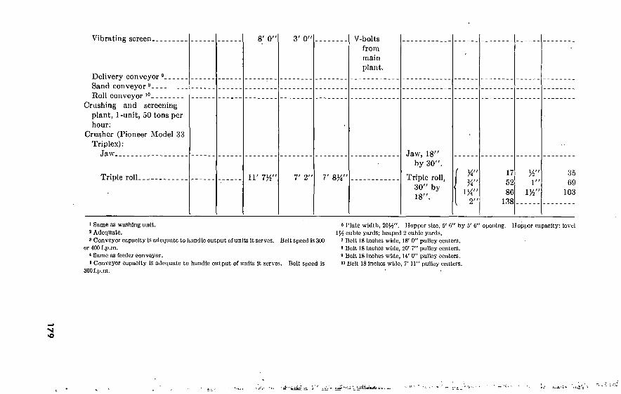
17
9
Vibrating screen. 8' 0' 3' 0"
Delivery conveyor s Sand conveyor 9 Roll conveyor 10
Crashing and screening plant, 1-unit, 50 tons per hour:
Crusher (Pioneer Model 33 Triplex):
Jaw
Triple roll- 11' 7y2" 7' 2' 7' 8K"
V-bolts from main plant.
Jaw, 18'' by 30".
Triple roll, 30" by 18".
%" %"
VA" 2"
17 52 86
138
W 35 1" 69
1%" 103
1 Same as washing unit. 2 Adequate. 2 Conveyor capacity Is adequate to handle output of units It serves. Belt speed Is 3U0
or 400 f.p.m. * Same os feeder conveyor. » Conveyor capacity Is adequate to handle output of units It serves. Belt speed Is
SOOf.p.m.
2 Plate width, Hopper size, f/ 0" by 5' G" opening. Hopper capacity: level cubic yards; heaped 2 cubic yards.
2 Belt 18 inches wide, 18' 0" pulley centers. 2 Belt 18 Inches wide, 20' 7" pulley centers. 2 Belt 18 inches wide, IV 0" pulley centers.
Belt 18 Inches wide, 7' 11" pulley centers.
Vi

55. Maintenance a. Ditches and culverts must be kept open on all roads. Mainte-
nance and repairs required on various types of surface are shown in table 58.
Table 58. Road Maintenance and Repair
Type of surface Maintenance Bepair
Portland-cement concrete, asphal- tic concrete, brick, stone, or wood block.
Bituminous sur- , faces.
Clean dust and dirt from joints and cracks and refill with hot asphalt, tar, or a cement grout.
Occasional renewal of wearing surface by adding seal coat with mineral- aggregate cover.
Repair by patching with bituminous premix, or with original material.
Soft spots and breaks: Remove surface; correct drainage, base and/or subgrade; trim and square area to be patched; replace sur- face with bituminous premix.
Ruts, waves, and shoves: Usually caused by excess bituminous material, improper curing or defective drainage. The latter may require complete removal of pavement. If pavement is roadmix type, scarify and disk material until broken up, blade
. from side to side of strip. If necessary add aggregate, reshape and roll. Apply seal coat if needed. In surface treatments; usually indicates bond between bituminous treatment and base course broken. Remove wearing course, recondition and reprime base, apply new surface treat- ment. Use surface material similar to original.
Worn and raveled surface: In mixed material, remove surface full depth over defective area, cut square or rectangular opening with vertical edges. Clean base and apply tack coat, place mix and tamp, roll and check surface. In penetration-macadam or sim- ilar surface, repair by surface treating affected area with ma- terial similar to original pave- ment.
180
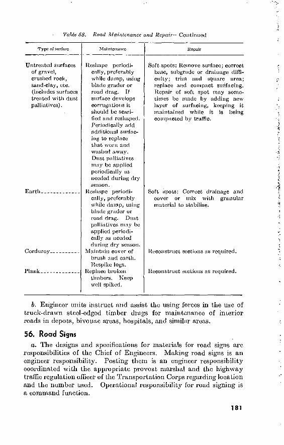
Tabic öS. Hoad Maintenance and Repair—Continued
Type of surface Maintenance Repair
Untreated surfaces of gravel, crushed rock, sand-clay, etc. (includes surfaces treated with dust palliatives).
Earth.
Corduroy.
Plank.
Reshape periodi- cally, preferably while damp, using blade grader or road drag. If surface develops corrugations it should be scari- fied and reshaped. Periodically add additional surfac- ing to replace that worn and washed away. Dust palliatives may be applied periodically as needed during dry season.
Reshape periodi- cally, preferably while damp, using blade grader or road drag. Dust palliatives may bo applied periodi- cally as needed during dry season.
Maintain cover of brush and earth. Respike logs.
Replace broken timbers. Keep well spiked.
Soft spots: Remove surface; correct base, subgrade or drainage diffi- culty; trim and square area; replace and compact surfacing. Repair of soft spot may some- times be made by adding new layer of surfacing, keeping it maintained while it is being compacted by traffic.
Soft spots: Correct drainage and cover or mix with granular material to stabilize.
Reconstruct sections as required.
Reconstruct sections as required.
b. Engineer units instruct and assist the using forces in the use of truck-drawn stccl-edgcd timber drags for maintenance of interior roads in depots, bivouac areas, hospitals, and similar areas.
56. Road Signs
a. The designs and specifications for materials for road signs are responsibilities of the Chief of Engineers. Making road signs is an engineer responsibility. Posting them is an engineer responsibility coordinated with the appropriate provost marshal and the highway traffic regulation officer of the Transportation Corps regarding location and the number used. Operational responsibility for road signing is a command function.
181

b. Figures 12 through 19 show typical road signs of various cate- gories. For further details see AR 420-72; the Manual on Uniform Traffic Control Devices dated 1948 (Public Roads Administration) as modified by the Revision dated 1954 (Bureau of Public Roads) ; and FM 5-36.
STRAIGHT ON TOWARD THE FRONT STRAIGHT ON AWAY FROM THE LINE FRONT LINE
TURN RIGHT
FORK RIGHT
SHARP TURN TOWARDS RIGHT REAR
TURN LEFT
FORK LEFT
SHARP TURN TOWARDS LEFT REAR
ALL DISKS HAVE MINIMUM DIAMETERS OF 1 FOOT.
Figure 12. Directional disk marking.
182

183 205
I FRONT
t 205
FRONT 205
MAIN SUPPLY ROUTE 205 FRONT GOING
TRAFFIC STRAIGHT ON
ALTERNATIVE FOR
SUPPLY ROUTE 205
FRONT GOING TRAF- FIC STRAIGHT ON
MAIN SUPPLY ROUTE
205 FRONT GOING
TRAFFIC TURN RIGHT
ALTERNATIVE FOR
MAIN SUPPLY ROUTE 205 TURN RIGHT
205
Î REAR
1 216
216
MAIN SUPPLY ROUTE 205 REAR GOING TRAF-
FIC STRAIGHT ON
ALTERNATIVE FOR
MAIN SUPPLY ROUTE
205 REAR GOING TRAF-
FIC STRAIGHT ON
LATERAL ROUTE 216
NORTH GOING TRAFFIC
TURN RIGHT
ALTERNATIVE FOR
LATERAL ROUTE 216
TURN RIGHT
ALL CIRCLES OR CIRCULAR DISKS HAVE MIN.DIA. OF 1 FOOT.
Figure IS. Route signs.
YL à

DETOUR
( 24" X 9" )
® N BD4
{ 40" X 24" )
PARIS t ORLEANS-»
( VARIABLE SIZE )
STOP AHEAD
{ 24" X 24")
FRANKFURT ( VERTICAL- 24" HORIZONTAL-
VARIABLE. MINIMUM-24")
ROAD CLOSED (40" X 24")
END DETOUR
( 40" X 24")
35B4
DRD.MAM CO
( 30" X 24"
Figure H. Guide signs.
BRIDGE OUT
(40" X 24’')
SLOW DO NOT ENTER ( 24' X 24" )
KEEP
RIGHT
( 12" X 18“ ) ■ (18!' X 24"
ONE WAY
(36" X 12" >
ND NO LEFT ANT TURN TME
(12" X 18")
END 3 5 MILE
SPEED ( 14" X 9" )
OS' X 24")
Figure 15. Regulatory signs.
SPEED LIMIT
50 (18" X 24")
184

CURVE TO RIGHT 24" X 24"
t WINDING CURVES
* 24 X 24
h T-JUNCTION
24" X 24"
SHARP CURVE TO RIGHT 24* X 24“
R R
RAILROAD CROSSING DIM.l 30" DIA.)
\T"/ PRIMARY ROAD CROSSING
SECONDARY ROAD 24’ X 24''
Figure 16. Warning signs.
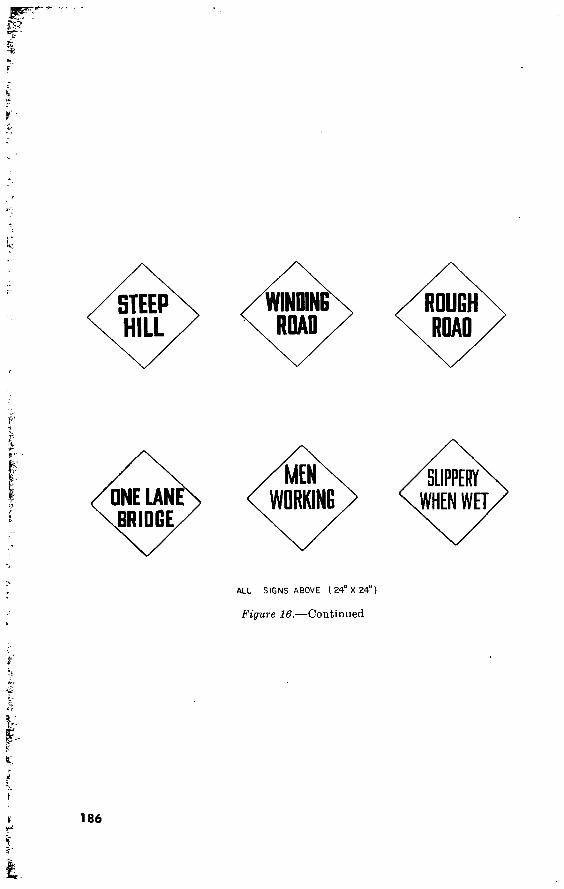
STEEP HILL
WINDING ROAD
ROUGH ROAD
ONE UNE BRIDGE
/MEN WORKING
SLIPPERY WHEN WET.
ALL SIGNS ABOVE ( 24" X 24" )
Figure 16.—Continued
186

BD 1 i (
V r
■'W1
BD I FLOATING BRIDEE
\u Vf. \ Ci./ ! '! » \(f
: ■ \
3D 40 H
( MINIMUM DIA. OF DISKS, 12 )
Figure 17. Bridge class and information signs.
187

80
60 ©
80 100 80 60
© (MINIMUM DIA. OF DISKS 12 )
Figure 18. Dual-class bridge signs.
188

© 40 40 80
y - ^
VcHIClES ABOVE CLASS 40 USE INSlDh LANE
WARNING SIGN FOR
TRAFFIC CONTROL
MINIMUM DIA OF DISKS 12")
Figure 19i Multilane bridge signs.
Section II. STREAM CROSSING EQUIPMENT
57. General The siting, design, and erection of standard, prefabricated, floating,
and fixed highway bridges are covered in the TM 5-270-series. Construction and logistical data pertinent to these bridges are tabu- lated in FM 101-10. Prefabricated semipermanent steel highway bridges for 30-, 60-, and 90-foot spans are covered in TM 5-285; typical semipermanent highway and railroad trestle bridges in TM 5-286; and prefabricated steel railroad bridges in the TM 5-370-series. TM 5-260 deals with the design principles underlying the construc- tion, maintenance, and use of all types of military bridges.
58. Panel Bridge, Bailey Type, M2 For detailed information on the Bailey type M2 panel bridge, see
TM 5-277.
59. Semipermanent Steel Highway Bridges, 30-, 60-, and 90-foot Spans
Data on semipermanent steel highway bridges, 30-, 60-, and 90-foot spans are given in table 59.
189

Table 59. Semipermanent Steel Highway Bridges, 30-, 60-, and 90-Foot Spans
Item
Type Class Caution class 1 Weight of one beam or truss,
pounds Weight, structural steel and
connections, pounds Measured tons, structural steel
and connections Quantity of lumber, board feet. Measured tons, lumber Man-hours to erect, average. _. Required abutment capacity,
tons
N ominal length
30 ft.
Deck I-beam 50 75
2, 600
12, 917
7. 55 3, 868
8. 05 453
70. 5
60 ft.
Deck I-beam 50 75
10, 000
45, 788
20. 31 7, 544
15. 70 1, 042
87. 5
90 ft.
Through truss 50 70
15, 000
61, 654
48. 56 10, 608
22. 10 1, 929
88. 5
> 1 vehicle on bridge at a time, vehicle on center line of bridge, no braking or gear shifting.
60. Prefabricated Railroad Bridges
There are three bridges in this category: The I-beam railroad bridge (TM 5-371), the unit construction railroad bridge (TM 5-372^, and the. ..through-truss railroad bridge (TM 5-373). The relations between type, loading, span length, and maximum speed for the foregoing are given in tables 60, 61, and 62. New equipment is under study which, if adopted, may take the place of the first two types and the semipermanent steel highway bridges described in TM 5-285 as well.
61. Floating Bridges Data on floating bridges is given in tables 63 and 63.1.
62. Rafts Data on rafts is given in table 64.
63. Boats
a. General. Below are summarized the principal characteristics of standard Army boats other than ponton boats. For further details see FM 5-271.
b. Assault Boat, Plastic, 16-Foot. The assault boat, plastic, 16-foot, replaced the assault boat, M2. It has a flat bottom, tapered bow, and square stem. It weighs 291 pounds and has a capacity of 3,375 pounds in currents up to 5 f.p.s. and 2,700 pounds in currents up to 8 f.p.s.
190

Table 60. I-Beam Railroad Bridge
Beam size Number of beams
in bridge Span
length (feet)
Maximum speed, mph, at Cooper’s loading of:
E-42H E-40
18" WF 55#. 15 16 17 18
19 20 21
40 40 25 25
40 40 40
40 40 40 25
40 40 40
40 40 40 40
40 40 40
24" WF 87#. 22 23 24 25 26 27 28 29
30 31 32 33 34 35
40 40 40 40 40 25 25 25
40 40 40 40 40 40
40 40 40 40 40 40 25 25
40 40 40 40 40 40
40 40 40 40 40 40 40 40
40 40 40 40 40 40
191 533500°—60 13

Table 61. Unit Construction Railroad Bridge
Type of bridge
Through truss.
Deck.
Number of trusses
Two.
Four.
Two.
Three.
Span length feet
55 60 65 70 75 80 85
75 80 85
¿5 60 65 70 75
75 80 85
Maximum speed, mph, at Cooper’s loadings of:
E-45
40 40 40 40 10
C) C)
40 40 40
40 40 40 40 10
40 40 40
E-42¡¿
40 40 40 40 25 10
(')
40 40 40
40 40 40 40 25
40 40 40
E-40
40 40 40 40 40 25 10
40 40 40
40 40 40 40 40
40 40 40
1 Not permitted.
Table 62. Through-Truss Railroad Bridge
Cooper’s loadings Maximum speeds in miles per hour for span lengths of:
92'-3" 102'-G" 112'-9’ 123'-0" 133'-3" 143'-6‘ 153'-9''
Two standard locomotives and and train:
E-45 E-42/2
E-40 One standard
locomotive and train :
E-45 E-42/2 E-40
40 40 40
40 40 40
40 40 40
40 40 40
40 40 40
40 40 40
40 40 40
40 40 40
10 20 40
40 40 40
10 10 20
20 40 40
C) 10 20
10 20 40
1 Dead slow.
192
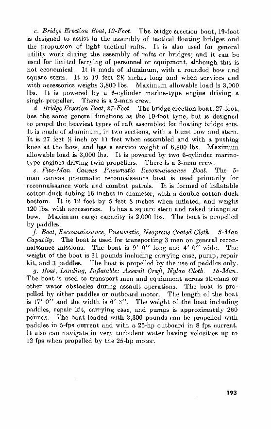
c. Bridge Erection Boat, 19-Foot. The bridge erection boat, 19-foot is designed to assist in the assembly of tactical floating bridges and the propulsion of light tactical rafts. It is also used for general utility work during the assembly of rafts or bridges; and it can be used for limited ferrying of personnel or equipment, although this is not economical. It is made of aluminum, with a rounded bow and square stern. It is 19 feet 2% inches long and when services and with accessories weighs 3,800 lbs. Maximum allowable load is 3,000 lbs. It is powered by a 6-cylinder marine-type engine driving a single propeller. There is a 2-man crew.
d. Bridge Erection Boat, 27-Foot. The bridge, erection boat, 27-foot, has the same general functions as the 19-foot type, but is designed to propel the heaviest types of raft assembled for floating bridge sets. It is made of aluminum, in two sections, with a blunt bow and. stern. It is 27 feet % inch by 11 feet when assembled and with a pushing knee at the bow, and has a service weight of 6,800 lbs. Maximum allowable load is 3,000 lbs. It is powered by two 6-cylinder marine- type engines driving twin propellers. There is a 2-man crew.
e. Five-Man Canvas Pneumatic Reconnaissance Boat. The 5- man canvas pneumatic reconnaissance boat is used primarily for reconnaissance work and combat patrols. It is formed of inflatable cotton-duck tubing 16 inches in diameter, with a double cotton-duck bottom. It is 12 feet by 5 feet 8 inches when inflated, and weighs 120 lbs. with accessories. It has a square stern and raked triangular bow. Maximum cargo capacity is 2,000 lbs. The boat is propelled by paddles.
/. Boat, Reconnaissance, Pneumatic, Neoprene Coated Cloth. 8-Man Capacity. The boat is used for transporting 3 men on general recon- naissance missions. The boat is 9' 0" long and 4' 0" wide. The weight of the boat is 31 pounds including carrying case, pump, repair kit, and 3 paddles. The boat is propelled by the use of paddles only.
g. Boat, Landing, Inflatable: Assault Craft, Nylon Cloth. 15-Man. The boat is used to transport men and equipment across streams or other water obstacles during assault operations. The boat is pro- pelled by either paddles or outboard motor. The length of the boat is 17' 0" and the width is 6' 3". The weight of the boat including paddles, repair kit, carrying case, and pumps is approximattly 260 pounds. The boat loaded with 3,300 pounds can be propelled with paddles in 5-fps current and with a 25-hp outboard in 8 fps current. It also can navigate in very turbulent water having velocities up to 12 fps when propelled by the 25-hp motor.
193

19
4
Tabic 68. Classes of Floating Bridges ■
Type of bridge
Aluminum footbridge.
M2 assault boat bridge
Normal con- struction.
Heinforced construc- tion.
Widened steel tread way bridge
Transportation ' • rèquired »
Assembly party 2
2-2J^t 6 by 6 cargo trucks with 2 pole tirs or 3 dump trucks.
l-2^t truck and 1 pole tir per 35 ft. of bridge.
l-2^t.truck and 1 pole tir per 24 ft. of bridge.
l-5t bridging truck per 24 ft. of bridge.
1 plat.
1 plat.
Mainte- nance crew
1 sqd.
1 sqd..
Class 3
Normal crossing * (posted capacity)
Caution crossing 3 Risk crossing 3
Stream velocities In feet per second
ü 11
Sfc.
1 tdwy bridge co
1 plus 1 combat co.
1 sqd.. 40 30
13
50 50 45 20
TraiTic capacity and vehicular distance for
safe crossings In daylight (except as otherwise
noted)7
Day:“75 men per minute. Night: 40 men per minute at 2*pacc dis- tance.
200 vehicles per hour; 90 ft. dis- tance be- tween vehicles.
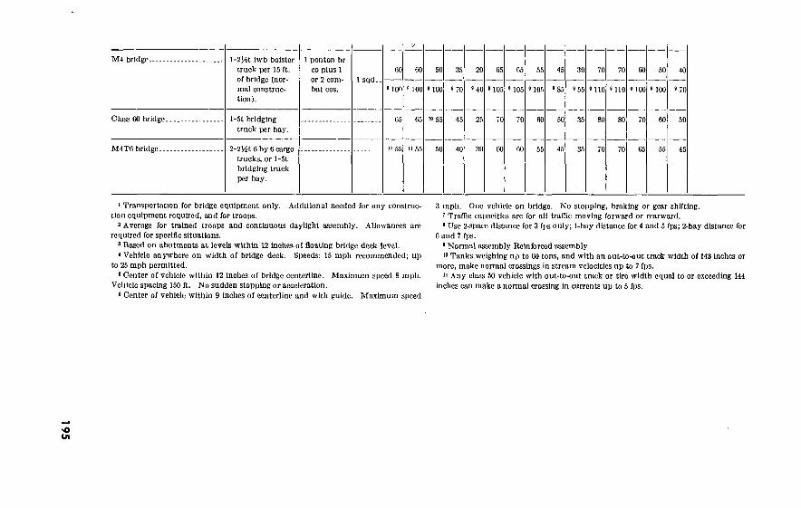
195 M4 bridge.
Class CO bridge.
M4TG bridge.
l-2^t iwb bolster truck per 15 ft. of bridge (nor- mal construc- tion).
]-5t bridging truck per bay.
2-2Ht 6 by 6 cargo trucks, or l-5t bridging truck per bay.
1 ponton br co plus 1 or 2 com- bat cos.
1 sqd.. 00
> ion
05
60
100
05
50
9 100
«0 55
35
9 70
20
8 40
25
30
05
J05
05
105
55
105
45
5 85
30
»55
70
110
70
»110
50
9 100
40
«70
45
1 Transportation for bridge equipment only. Additional needed for any construc- tion equipment required, and for troops.
2 Average for trained troops and continuous daylight assembly. Allowances arc required for specific situations.
8 Based on abutments at levels within 12 inches of floating bridge deck level. 4 Vehicle anywhere on width of bridge deck. Speeds: 15 mph recommended; up
to 25 mph permitted. 8 Center of vehicle within 12 Inches of bridge centerline. Maximum speed 8 mph.
Vehicle spacing 150 ft. No sudden stopping or acceleration. 6 Center of vehicle within 9 inches of centerline and with guide. Maximum speed
3 mph. One vehicle on bridge. No stopping, braking or gear shifting. 7 Traffic capacities arc for all traffic moving forward or rearward. 8 Use 2-space distance for 3 fps only; l-bay distance for 4 and 5 fps; 2-bay distance for
6 and 7 fps. 9 Normal assembly Reinforced assembly
Tanks weighing up to 00 tons, and with an out-to-out track width of 143 inches or more, make normal crossings in stream velocities up to 7 fps.
11 Any class 50 vehicle with out-to-out track or tire width equal to or exceeding 144 inches can make a normal crossing In currents up to 5 fps.

196
Table 6S.1. Dual Classification Floating Bridge Capacities
Bridge Type of constr. Safe Normal Caution Risk
F PS 9 11
M2 Assault boat bridge* Normal.
Rcinf. 13 13
Widened steel treadway bridge (w/piywood tdwy) (1). (45) 50
(45)
50 (35)
40
(25)
30 (12)
15 (48)
51 (47)
50 (43)
4G (31)
34 (10)
10 (55)
58
(54)
57
(52)
55 (41)
44
Class 60 bridge. Normal. (00)
65 (55)
65 (45)
55
(35)
45
(22)
25 (65)
70
(62)
07
(56)
01
(45) 40
(34)
37
(75)
79
(72) (07)
72
Reinf. (2). (85)
85
(85)
85
(85)
85
(05)
70
(30) 35
(90)
90
(90)
90
(90)
90
(75)
79
(47)
51
(100)
100
(100)
100
(100)
100
(25)
28
(57) 02
(40)
50
(90)
93
(70)
74
M4 bridge.. Normal (3). (00)
GO (60)
GO (45)
50 (30)
35
(18) 20
(08) 08
(65) 05
(58) 59
(44) 46
(29) 31
(72) 72
(68)
08 (61)
52 (53)
54
Reinf. (4). (100)
100 000)
100 000)
1-0 (70)
70 (35)
40 (105)
105 005)
105 005)
105 (85)
85 (55)
55 (HO)
110 (HO)
110
(HO)
no
(37)
39
(100)
100 (70)
70
M4T6 bridge. (50) (45) (40) (30) (25) (60) (58) (54) (45) (35) (68) (66) (62) (54) (43)
Notes, l. ‘Wheeled and track vehicles have the same rating.
2. Upper figure represents wheel load class. Example (43) Lower figure represents tracked load class. 45
3. (1) Vehicles required to use plywood treadway lane limited to Class 16
Safe, Class 18 Caution, Class 24 Risk. 4. (2) Ratings given are for floating portion of bridge. End span ratings with
present superstructure limited to Class 70 Safe, Class 80 Caution, and
Class 90 Risk. Development of satisfactory landing bay not yet com-
plete. 5. (3) Ratings given arc for an 18-balk roadway and a 22-balk deck.
6. (4) Ratings given arc for a 20-balk roadway and a 24-balk deck In the floating portion, and a 20-balk roadway and a 22-balk deck with a superimposed
deck in the end span.

197 Table 64- Classes of Rafts
Type of raft
Infantry support.
M4 of.
Class 60.
Transportation required (for raft equipment only.
Additional needed for construction equipment
and troops)
Class of raft and number of power units needed Length
Risk crossing Type of power unit required
Number of pontons or
floats
Operat Normal crossing* Assem bly
party Avail able for
load> Ing ®
ing Overall
including ramps
crew Stream velocity fps Stream velocity fps .
No. Unit units
2>$-ton cargo truck w/pole
trailer. 38-0 24-0
Outboard 2H*ton cargo truck w/polc
trailer.
1 plat 1 sqd. 35-9 motors— 50-0
horse power
62-0 47'-9"
50) (50) (50 (40 (55 553 (55 45
27-foot ’ bridge erection
boats.«1
2^-ton bolster truck with
trailer. 75) 87'-0-M 1 plat.. 1 sqd (70) (70) (65) 50 (75) (75 (55 5l'-8
(90 85) (80) (55) (90 (90 (65)
5-ton bridge
truck. 45) 4. Normal 92-5 5l'-0 40 40) (35) (25) (50) (50 (35
•Number in parentheses represents wheeled vehicle class. Number without parentheses represents tracked vehicle class.
See notes at end of table.

00
Table 64. Classes of Rafts—Continued ,
Type of raft
Class 60.
M4T6.
Number of ponton? or
floats'
4,-Reinforced..
5, Normal.
5, Reinforced.
5, Reinforced.
6, Reinforced..
6, Reinforced..
5, Reinforced..
Length
Overall including
ramps
83'-!'!
107'-5"
92'-5/'
SS'-l"
92'-5"
87'-l"
Avail- able for
load- ing »
40'-0"
66'-0"
54'-6"
43'-9'
sr-o"
50'-10"
5l'-8"
Assem- bly
party
Operat- ing
crew
1 plat..
1 plat..
Class of raft and number of power units needed’ *»
1 sqd..
I sqd..
Normal crossing*
Stream velocity fps
(45)\
55
(50>
55
(55)\
60
(60 J'
65
(65)\
75
(60^
70
(50>
55
(60J'
65
(40>
45
35
(50)\
55
(55p
60
(60)\
65
75
(60>
70
(45>
50
(60>
65
9
(40>
45
(45)\
50
(50r
55
(60)\
65
(55>
60
(35>
40
(55>
60
(25)\
30
(30>
35
(35^
40
(45)\
50
(50>
55
(45^
50
(30>
35
(45>
50
Risk crossing*
Stream velocity fps
(55)\
60
(60)\
65
(00>
70
(70)\ 75
(80)\
90
(75>
85
(60r
65
(70>
75
■r •
(50)\
55
.3
45)
(60)\
65
60)
(70>
75 -\
(80>
90
(75)\
85
(55>
'60
OQ>
75
50)
55)
(70>
■80
(65>
75 .
(45>
50
(65>
•70
(35)\
40
(40)\
45
(45)
55)
60)
(55>
65
(35>
40
(55>
‘ Type of power unit
required
27-foot
bridge
erection
boats.«1
27-foot
bridge
erection
boats.«1
Transportation required (for raft equipment only. .Additional needed for construction equipment
and troops)
No. units
Unit
5-ton bridge
truck.
5-ton bridge
trucks.
5-ton bridge
trucks.
5-ton bridge
trucks.
5-ton bridge,
truck.
2^-ton cargo truck.

66
L NUMBER OF POWER UNITS NEEDED.
CLASS (ont or mora vehicles).
NUMBER OF POWER UNITS NEEDED.
SINGLE VEHICLE CAPACITY
DOUBLE VEHICLE CAPACITY (vehicles should be approsimotely equal m weight )
Operating characteristics of rafts
Number of round trips per hr in cur- rents of 5 fps in daylight (reduce 50% for night or adverse conditions)
Number of rafts which can be used efficiently at one site
Stream width (feet)
250 500 lr000
•Number in parentheses represents wheeled vehicle class. Number without parentheses represents tracked vehicle class.
* Measured from outside edge to outside edge of end pontons or float saddle beams, b Capacities are based on loading rafts with center of gravity of loads 6" downstream
from top of raft and on properly inflated floats. * One 19-foot bridge erection boat per raft, in current of 9 fps. d One 19-foot bridge erection boat may be used in currents not over 5 fps. In currents
of 5 fps and over, normally two 19-foot bridge erection boats may be substituted for one 27-foot boat.
e Extreme caution is required in loading and unloading vehicles weighing more than 70 tons.
f Roadway width consists of 18 balk between curbs with 22 balk overall. * Roadway width consists of 17 balk between curbs with 20 balk overall.
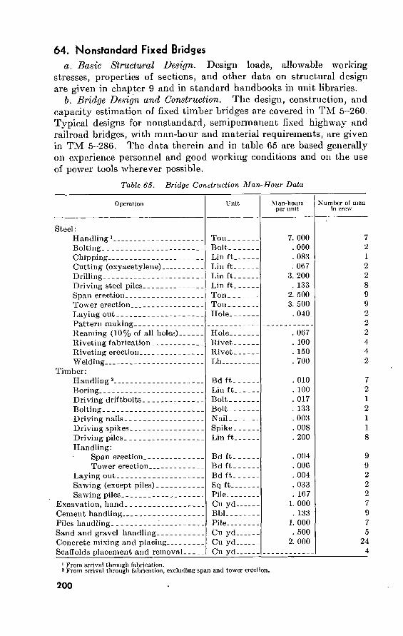
64. Nonstandard Fixed Bridges
a. Basic Structural Design. Design loads, allowable working stresses, properties of sections, and other data on structural design are given in chapter 9 and in standard handbooks in unit libraries.
b. Bridge Design and Construction. The design, construction, and capacity estimation of fixed timber bridges are covered in TM 5-260. Typical designs for nonstandard, semipermanent fixed highway and railroad bridges, with man-hour and material requirements, are given in TM 5-286. The data therein and in table 65 are based generally on experience personnel and good working conditions and on the use of power tools wherever possible.
Table 65. Bridge Construction Man-Hour Data
Operation
Steel : Handling 1 Bolting Chipping Cutting (oxyacetylene) Drilling Driving steel piles Span erection Tower erection Laying out Pattern making Reaming (10% of all holes)-- Riveting fabrication Riveting erection Welding
Timber: Handling 2 Boring Driving driftbolts Bolting Driving nails Driving spikes Driving piles Handling:
Span erection Tower erection
Laying out Sawing (except piles) Sawing piles
Excavation, hand Cement handling Piles handling J Sand and gravel handling Concrete mixing and placing Scaffolds placement and removal_
Unit
Ton. _ Bolt- _ Lin ft_ Lin ft- Lin ft_ Lin ft_ Ton_ . Ton _ - Hole.-
Hole_- Rivet_ Rivet- Lb—.
Bd ft. Lin ft_ Bolt- _ Bolt - - Nail- - Spike- Lin ft_
Bd ft.. Bd ft-. Bd ft-. Sq ft-_ Pile Cu yd- Bbl Pile Cu yd. Cu yd- Cu yd_
Man-hours per unit
7. 000 . 060 . 083 . 067
3. 200 . 133
2. 500 3. 500
. 040
. 067
. 100
. 150
. 700
. 010
. 100
. 017
. 133
. 003
. 008
. 200
. 004
. 006
. 004
. 033
. 167 1. 000
. 133 1. 000
. 500 2. 000
Number of men in crew
7 2 1 2 2 8 9 9 2 2 2 4 4 2
7 2 1 2 1 1
8
9 9 2 2 2 7 9 7 5
24 4
1 From arrive! through fabrication. 1 From arrival through fabrication, excluding span and tower erection.
200
65. Highway Bridge Stringers a. For two-lane bridges with an 18- to 30-foot roadway and a
6-inch timber floor, in which the stringer depth is not less than yiS of the span, the total section modulus required for timber stringers for various classes and spans is shown in table 66. For a single-lane bridge less than 18 feet wide, use 0.5 of the section modulus tabulated. For round timber stringers, use 0.6 of diameter as width, and di- ameter as depth.
b. For stringer depths from 6 to 24 inches, the section modulus per inch width of rectangular timber stringers is tabulated below. (For spans less than 13 times the stringer depth, examine for hori- zontal shear using the data in paragraph 163c.)
Depth 6 8 10 12 14 16 18 20 22 24 Section modulus 6 11 16 24 33 43 54 67 81 96
c. Under the same conditions as in a above as to widths and num- ber of lanes, and where the stringer depth is not less than %0 of the span, the total section modulus required in steel stringers is shown in table 67.
d. Section moduli for various steel beams are given in paragraphs 151 to 160.
e. Examples: (1) A bridge with a 22-foot roadway has a timber floor carried
by six 6- by 16-inch stringers over a 13-foot span. De- termine the class. Section modulus from b above is 43 by 36=1,548. By interpolation in the table in a above, the class is 23.
(2) Determine the number of 24 WF 76 stringers for a one-lane class 40 bridge with a 6-inch timber floor and a span of 60 feet. From c above, a total section modulus of 1,935 is required for a two-lane bridge; 0.5X1935 or 968 is the total section modulus required for one lane. From paragraph 139, a 24 WF 76 has a section modulus of 175.4; 968/175.4 = 5.5; therefore, use 6 stringers.
Section III. CABLEWAYS AND TRAMWAYS
66. Characteristics
Logistical data and other characteristics of cableways and tramways are shown in table 68. For further details see TM 5-270.
67. Details
Details of the cableways and tramways listed in table 61 are given in figures 20 through 23.
201
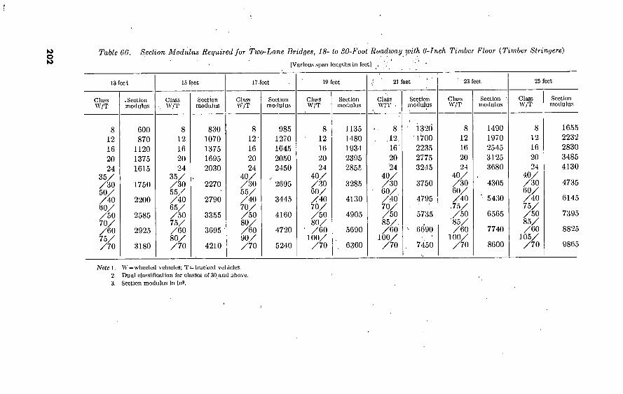
202 Table 66. Section Modulus Required for Two-Lane Bridges, 18- lo 30-Fool Roadway with 6-Inch Timber Floor (Timber Stringers)
[Various span lengths in feet]
13 feet
Class W/T
^Section modulus
8 12
16 20
24 35/ /30 50/ /40 60/ /50 70/ /60 75/ /70
600 870
1120 1375 1615
1750
2200
2585
2925
3180
15 feet
Class W/T
8 12
16 20
24 35/ /30 55/ / 40 65/ /50 75/ /60 80/ /70
Section modulus
830 1070 1375 1695 2030
2270
2790
3355
3695
4210
17 feet
Class W/T
8 12'
16 20 24
40/ /30 55/ /40 70/ /50 80/ /60 90/ /70
Section modulus
985 1270 1645 2050 2450
2695
3445
4160
4720
5240
19 feet
Class W/T
8 12
16 20 24
40/ /30 60/ /40 70/ /50 80/
' /60 100/ /70
Section modulus
J135 1480 1934 2395 2855
3285
4130
4905
5690
6360
21 feet
Clats W/T
,12.
16' 20 24
40/ /30 60/ / 40 70/ /50 85/. /60
100/ /70
Section modulus
1320 •1700 2235 2775 3245
3750
4795
5735
6690
7450
23 feet
Class W/T
8 12
16 20 24
40/ /30 60/ / 40
.75/ /50
'85/ /60
100/ /70
Section modulus
1490 1970 2545 3125 3680
4305
5430
6565
7740
8600
25 feet
Class W/T
8 12
16 20 24
40/ /30 60/ /40 75/ /50 85/ /60
105/ /70
Section modulus
1655 2232 2830 3485 4130
4735
6145
7395
8825
9865
Noie 1. W = \vhecled vehicles; T=tracked vehicles. 2. Dual classification for classes of 30 and above. 3. Section modulus In !n3.

Table 67. Section Modulus Required for Two-Lane Bridges, 18- to 80-foot Roadway with 6-Inch Timber Floor (Steel Stringers)
[Various span lengths in feet]
15 feet 20 feet 25 feet 30 feet 40 feet 50 feet 00 feet 80 feet 100 feet
Class W/T
Section modulus
Class W/T
Section mod- ulus
Class W/T
Section mod- ulus
Class W/T
Section mod- ulus
Class W/T
Section mod- ulus
Class W/T
Section mod- ulus
Class W/T
Section mod- ulus
Class W/T
Section mod- ulus
Class W/T
Section mod- ulus
85 120
140 170 205
235
285
340
405
425
8 12
16 20 24
40/ /30 60/ /40 70/ /50 85/ /60
100/ /70
120 160 210 255 305
350
450
535
620
700
8 12
12
20 24
40/ /30 60/ /40 75/ /50 85/ /60
105/ /70
165 220 280 345 410
480
615
745
865
975
8 12
16 20
24 40/ /30 60/ /40 70/ /50 85/ /60
100/ /70
210 275 360 440 515
615
780
940
1115
1255
8 12
12 20 24
35/ /30 50/ / 40 65/ /50 80/ /60 95/ /70
310 410 535 640 745
885
1150
1395
1625
1870
8 12
16 20 24
35/ /30 45/ /40 60/ /so 70/ /60 85/ /70
430 585 705 880
1020
1190
1525
1855
2160
2500
8 12
16 20 24
30/ /30 40/ /40 55/ /50 75/ /60 80/ /70
550 775 920
1145 1330
1500
1935
2350
2720
3195
30/ /3 40/ /4 50/ /5 60/
70/
8 12
16 20 24
V '30
V '40 y 'so y '60 y 'Vo
895 1195 1415 1755 2025
2305
2880
3485
4020
4630
8 12
16 20 24
30/ /so 40/ / 40 50/ /50 60/ /60 70/ /TO
1300 1690 2000 2465 2830
3275
4055
4850
5585
6410
Note 1. \V=wheeled vehicles; T=tracked vehicles.
2. Dual classification for classes of 30 and above.
3. Section modulus in ins.

20
4
Typo
Medium cableway
Pioneer light aerial tramway and cableway, Ml.
Light aerial tram- way, M2 (exten- sion set also avail- able).
Table 68. Logistical Data and Other Characteristics of Cableways and Tramways
Issue Compositiou Transportation
Class IV.
Class IV.
Class IV.
2sectionalized towers 1 carriage 2 keepers 1 drive unit 1 hoist unit Accessories, tools,
and tackle. 1 cableway carriage 6 tramway or cable-
way carriages. 3 tramway carriers
(7 ft). 1 drive unit 2 toboggans 1 lower terminal 1 upper terminal 12 intermediate
towers. 1 power unit 4 carriers Accessories, tools,
and tackle.
4 2^-ton trucks or
7 l)2-ton trucks
1 2^-ton truck or
2 1’4-ton trucks or
9 )4-ton trailers or
9 J4-ton trucks 4 2J4-tou trucks
or 0 l)2-ton trucks
or 35 )4-ton trucks
or 35 %-ton trailers
Capacity Length Construction
Personnel Time
Carrier load 3,000 pounds; approxi- mately 17 tons per hour, over 1,000 ft gap.
1,200 ft.. 2 platoons.. 5 hr.
Tramway-carrier load 350 pounds.
Cableway-carrier load 2,000 pounds approximately 10 fps.
2,000 ft.. 2 platoons. .
1,500 ft.. 1 platoon
10 hr.
5 hr.
Carrier load 350 pounds approxi- mately 1 ton per hour over 3,000 ft length.
3,000 ft.. 1 company . 24 hr.

: W
sS<^ ORIVE 13—V -UNITIS Z
ïdSavW’V" SEO?
IL CARRIAGE / 13 y^KEEPER 10 |3 VXAV
35»* Afi 7 H Q'HOIST-; |l I ASSEMBLY I2u/f7^
«s> PLAN ?^Âdr 85’ TO 125* POR j4tí¡¿ |¡ 63' TOWER HALFSPAN
/2I
HALF SPANS CARRIAGE
KEEPER •KEEPERn -/
kv-WEIGHTEO PIVOTED VFALL BLOCK fSzTOWER“
PIVOTED ® -TOWER V OWER3BäSE 14
^ 24' iA
RIVE SPOOL
45-MAXV°WER BAS.E 24
Br,
HOIST
A DRUM SPAN (MAXIMUM 1200-1
'*‘83* TO 125* FOR ALL—1
GUYS WITH 63' TOWER MAXIMUM ANGLE 40* 7 FOR TRACK CABLE ^ AND BACK GUYS
9
MAXIMUM ANGLE 40« FOR TRACK CABLE AND
12 BACK GUYS
V
2
^DEADMAN ANCHOR
NEAR SIDE
23 23 PROVIDE WOOD CRIBBING UNDER TOWER BASE WHEN NECESSARY
^ ELEVATION 0
'SECTION A-A SECTION B-B ' FAR SIDE
Ik-Inch cable for track-cable anchor. (2 part*) H-Inch cable for haul-rope anchor, (2 part*) H-Inch cable for fall-rope anchor, (2 ports) ' H-Inch cable, (2 parts) Triple block Double block Single block Cable grip, wedge type H-mch track coble, 4x19, 750 feel %-mch haul rope, Ax!9, 19$ H-mch fall rope, 6x19, IPS fe-inch guy cable, 6x19, IPS, 300 feet
13. H-Inch guy coble, 6x19, IPS 14. H-Inch wedge socket, H-inch J and E tumbwdde 15. Steel picket holdfast 16. Holdfast 17. H-inch cable sling 18. Hand-winch anchor i 19. Hand winch, 5-ton 20. H-Inch coble, 6x19, 4Q0 feet 21. Wire-rope coupling 22. H-mch cable, 6x19, IPS, for adjusting tension In haul rope 23. Stakes 24. H-inch cable, (2 parts)
lembly
Figure 20. Medium cableway.
PIONEER LIGHT AERÍA1MRAMWAY AND CABLEWAY 1» AS A TRAM WAT
4k
m TRACK CABLE BiHAUL ROPE
m. UNIVERSAL CARRIAGE
m
m
POWER UNIT msm
Figure 21. Pioneer tramway.
205

PIONEER LIGHT AERIAL TRAMWAY -, AS A CABLEWAY
TRACK‘CABLEt
WËÊk m m
GARRIASE CABLEWAY
1
LOADING
UNIT POWER
urn Mi
w i UNLOADING'TERMINAL Í
m^tsaiitßsmäsm
Ifl
~JÈÊËMM§S^
TERMINAL wÆMmmm Figure 22. Pioneer cableway.
LIGHT AERIAL TRAMWAY ss
UPPER TERMINAL
i INTERMEDIATE TOWERS
* JT'HAUL CABLE TRACK CABLES
^ ^CARRIER m Tmm mi
IM ^"juLOWER TERMINAL
Figure 23. Light aerial tramway, M2.
206

CHAPTER 7
PONTOON GEAR
68. General Tlie Steel pontoons used consist of hollow steel boxes, designed to
be assembled into floating structures of various sizes, shapes, and types. Full details are contained in Pontoon Gear Handbook, Navdocks TP-PL-7, Department of the Navy, Bureau of Yards and Docks.
69. Pontoons and Accessories a. General. There are four types of pontoons, illustrated in figure
24 and described in b through e below. b. The T6B or Rectangular Pontoon^ 'The T6B is 5 feet 'A inch by
7 feet in deck area and 5 feet % inch deep. The side, end, deck, and bilge plating is /(e inch thick. The deck is of checkered plate. Four 2-inch-diameter plugged holes are provided near the corners on one side plate for air, sea cocks, drain, or siphon connection. The pontoon weighs 2,000 pounds and has a volume of 175 cubic feet.
c. The T7A or Curved-Bilge Pontoon. The T7A has the same depth as the T6B, but it has a curved bilge and its deck is 7 feet square. The side, deck, and end plates are ?i6 inch thick; the bilge plating is % inch thick. The deck is of checkered plate. Four 2-inch-diameter plugged holes are provided in the side plate (the plate opposite the curved end). It is used for the curved bow and stern of barges- It weighs 2,800 pounds and has a volume of 189 cubic feet.
d. The T8 or Sloped-Deck Pontoon. The T8 is 5 feet 2% inches by 7 feet in deck area and is inclined. The depth is 4 feet 11% inches at one end and 3 feet 6 inches, at the other. The bottom is horizontal. All the plating is inch thick. The deck is checkered. There are two 2-inch-diameter plugged holes in the deep end.
e. The Til or Ramp-End Pontoon. The Til has the same inclined- dock area as the T8. The offshore end is 3 feet 6 inches deep; the inshore end 1 foot. The bottom is horizontal for the first 1 foot 8 inches, and then pitches upward. The deck is %6 inch checkered steel plate, the side and end plates %6 inch plain, the bilge plating % inch plain. The front vertical edges should be protected by welding on fenders consisting of half-sections of 6-inch steel pipe. There are two 2-inch-diameter plugged holes in the deep end.
207 533506o—GO 14

T6B, RECTANGULAR PONTOON." T7A, CURVED-B1LRE PONTOON.
T8, SLOPED-DECK PONTOON. in^RAMP-END PONTOON..I
Figure 24* U.S, Navy 'pontoons.
j. Assembly Angles. The three standard sizes of steel assembly angles are 6 by 6 by % inches, 6 by 6 by % inches, and 8 by 8 by inches. In assembling pontoons, the size of angle used depends on the nature and size of the assembly and the rigidity required. The angles are fitted with wedge bars, to which the pontoons are attached by the jewelry, and with }¿-turn breech-plug-slice end couplings for great lengths of assembly. Assembly angles can be altered by cutting and welding but cannot be improvised in the field because of the ac- curacy required in the spacing of the wedge bars.
g. Sets. The pontoons, assembly angles, jewelry, and other acces- sories and special parts are made up and shipped in standard sets for field assembly into barges, floating bridges, causeways, floating wharves, drydocks, and other structures.
70. Pontoon Assemblies (General) The standard sets of pontoons and accessories can be assembled
into floating units of various types and sizes. These include barges, floating bridges, causeways, floating wharves, drydocks, and other
208

structures. The practicability of any proposed assembly can be determined by making a parts list of the units needed and comparing it with the packing lists for standard séts as given in the Pontoon Gear Handbook.
71. Barges
a. Use. Pontoon barges can be used in a variety of situations as substitutes for ordinary rigid barges. They can also be equipped for use as cranes, piledrivers, drill rigs, and other special-purpose floating plant. If equipped with special inboard or outboard propul- sion units, they can be used for icebreakers or tugboats.
b. Assembling. Normally, a string of pontoons of a length depend- ing on the desired length of the barge is first assembled and launched. T7A pontoons are used for the ends and T6B for the rest of the string (fig. 25). Other strings arc similarly assembled and launched, and the strings are then connected side by side to give a barge of the desired width. Assembly is by link-and-pin connection at the top angles and by tie rods near the bottom, as shown in figure 26. Installa- tion of A13 deck-closure channels (8-inch ship channel, 18.7 pounds, 5 feet 10% inches long) as shown in figure 27 completes the assembly for standard purposes. Figure 27 also shows the method, of determining the precise length of a string. Accessories to permit other , types of closure and also cleats, chocks, bollards, bits, etc., are available in the standard sets.
I X 12
I x 13
32 - 1 i?—H BARGE STRINGS
I I I I B IB
43' efr" B2 TH
k i i r i i i J-YïA B 3
I 72- 8" i P BSK) HF SHF
WIDTH OF STONG a TO a ANGLES FOR 1X5 ft IX T • 7** I
ALL OTHERS'
“WB PF WF“ .
k I I I I I I I "IT I T'715-2; B9f FM B9M
BBM ~KTF~ M^B,n _ . FM BIS FM B9M 8
U '°7-5 fri r B0M MF BIO UF BSF "
kl I r I I brr^r-r? ■ ITI i->-r*v
B9F FM BIO FM B9M FM BIO FM
142" 2*
MF BIO MF BWM BIO ri i i i i B9M FM BIO FM B9F FM BIO
17«" I
UË BIO MF BIO MF BIO MF X 30
BBF FM BIO FM BIO FM BIO FM
Figure 25. Side elevations of barge strings.
209

3(5) 7'-1 5/0" FOR 6"i 6% 3/0" ASSEM0LY ANGLES
S©?'-! 7/0" FOR 6“i6"« 1/2" AND 0"i0“» 1/2“ ASSEMBLY ANGLES
n ASSE MB NCLES I \s
N ^
16 LINK T6
LINK-AND-PIN ASSEMBLY
TIE RODS ^■A-15 YOKE
/ ^AM BOLT
AI5
Figure 26. Lateral assembly of barge strings.
O
AI3
T 6
ASSEMBLY ANGLES
NOTE:
To determine length of any string, add 9" for each longitudinal space between pontons.
E.g. length of ó x 16 barge: 2 Pontons T 7 @ 7'-0" = M'-O"
16 Pontons T 6 @ 5'”0^"= SO'-S" 17 Spaces @ 9" = 12'~9"
Total length 107'-5"*
Figure 27. Deck-closure channels; determining length of string.
c. Buoyancy and Capacity. Pontoon barges up to 6 by 18, about 43 feet by 107 feet and rated at 250 tons with 48-inch draft, are designed to carry a load at the center point heavy enough to bring the deck awash. For longer barges, the maximum load the barge can float must be distributed over at least the center 6 pontoons of a 24-long barge and at least the center 12 pontoons of a 30-long floating structure. Table 69 shows the load capacities, in tons, of certain standard barge assemblies.
Table 69. Standard Barge Assemblies
Number of pontoons wide x long
3 x 7-, 4 x 12. 5 x 12. 6 x 18. 6 X 30-
Capacity (tons)
50 100 125 250 500
Nominal width and length (feet)
21 x 43— 28 x 72.. 35 x 72_. 43 x 107. 43 x 175.
Oraft
Light (inches)
20 20 20 20 20
Loaded (inches)
48 44 48 48 48
210

72. Bridges
a. Standard Bridge Units. The term “standard bridge unit” is normally applied by the Navy to an assembly of pontoons used to connect a floating pontoon wharf to the shore. Such units may also be used to bridge a waterway. The standard units are:
(1) The 2-by-12 bridge unit, composed of 2 strings each containing 10 intermediate T6B and 2 end T7A pontoons.
(2) The 4-by-18 bridge unit, composed of 4 strings each contain- ing 16 intermediate T6B and 2 end T7A pontoons.
b. Bridge Strings. Strings of pontoons, known as bridge strings, are also used to bridge a waterway. Normally they arc made of T6B pontoons. Figure 28 shows the side elevations of such bridge strings. Any desired width can be attained by assembling strings laterally.
c. Bridging a Waterway. The strings or units used for this purpose are assembled, launched, and floated into position. The bridge must be anchored and the approaches prepared, as in the case of Army pontoon equipment. Anchors are not provided with the standard sets. T8 and Til pontoons may be used at the shore ends. To adjust the length of unit assemblies to the width of the river, strings or units may be lapped in midstream, care being taken to make the lap long enough for vehicles to negotiate (figs. 29 and 30). Acting as a beam, a 2-by-12 pontoon bridge, supported only at each end, will carry a 40-ton vehicle at its center.
IXS 4 — K
IT -4 J i r.Md -T / 3* Í5-2T
U 34 - ° 6 -I
B* 15
BRIDGE STRINGS
WIDTH Of STRING 0. TO 0. ANGLES C 7 *- I 7/g
F— FEMALE BAR BREECH PLUG SPLICE
M— MALE BAR BREECH PLUG SPLICE
'-•2 i Ti i Ti i f i i-n-tV BIF
BIM
BT-jrJs
'i“5 v-Frm-rr i in ~r BIF
Mf bUTMF EF H
FM BI3 FM
105- O'
MF BIF BIM BIO
rTTTT».-»y 1X18 »"-4-1 I I BIF BIO FM # BIM
139-9*
BIO MF BIM BIO MF
îü*r IX 24
BIO FM 174-6 H
BIM FM B 10 FM
MF BIO BIO MF BIO Bl M MF MF BIF
1X30
BIF FM BIO FM BIO FM BIO FM BIM
Figure 28. Side elevations of bridge strings.
211

ANCHOR
/
BRIDGE TO BRIDGE CONNECTION
• 1
Figure 29. A bridge made of standard 2 by 12 units, lapped in midstream.
73. Standard Causeway This assembly, made like a 2-by-30 barge, about 14 feet by 175
feet, is side-carried on LST’s and launched to permit dry landings on flat beaches. The causeway units can be assembled later for other bridge, wharf, or barge purposes. End pontoons are Til.
74. Wharves a. The standard sizes are 5 by 12, about 36 by 70 feet, and 7 by 60,
about 50 feet by 350 feet. All pontoons are T6B. b. Wharves 6 or more pontoons wide and 72 pontoons long, about
43 feet wide by 420 feet long, have been used satisfactorily for un- loading cargo ships of Victory and Liberty type (fig. 31). To have adequate depth alongside, they must normally be moored offshore and fitted with bridge approaches. Three approaches, each 4 pon- toons wide, are usually adequate.
c. In protected water with depths and bottom materials suitable for pile dolphins, there is no structural limitation on the size of either marginal or finger-pier floating wharves. Satisfactory moor- ings for such wharves have been developed by omitting one T6B pontoon at each corner and at intervals along the face and driving a pile cluster in each of the openings thus provided. The pile clus- ters also serve as ship moorings and as fenders to hold hulls away from the wharf.
212

ZZZZZZZZZZZZZZZZ.
í
C°) 0
U
' V
\ x\
Figure 30. Bridge-lo-bridge connection.
213

214
ANCHOR-*,
^SHIP S ANCHOR
SINKER
BUOY
SHIPS
ANCHOR
CARGO SHIP
OON.WHARF 7x72 PON
14 TURNBUCKLE Ij TURNBUCKLE I? WIRE ROPE I ¿"WIRE ROPE
-CJ4-W J «ARE ROPE
y/\v X WIRE ROPE
WIRE ROPE WIRE ROPE
X
a
\ ' I 1
ï, K
\ ■ I S' y
Figure SI. A 7-by-72 floating wharf, showing typical moorings.
CHAPTER 8
UTILITIES
Section I. WATER SUPPLY AND DISTRIBUTION
75. General The water requirements of troops under varióus service conditions
and the capacities of water-supply and distribution equipment are given in FM 101-10. Related publications dealing with specialized aspects of the problem are TM 5-295 and TM 5-297.
76. Responsibilities. a. Unit Commander. It is the responsibility of the unit commander
to provide units and individuals of his command with the required amount of safe drinking water at all times. He must make clear to every individual the danger in drinking unsafe water. He must enforce strict water discipline so that men—
(1) Drink only treated or approved water. (2) Don’t waste purified water. (3) Protect sources of water by good sanitary discipline.
b. Corps of Engineers. The Corps of Engineers is responsible for making available a supply of approved water for all purposes to all Army units. It is responsible for the design, procurement, installa- tion, operation, and maintenance of water-supply equipment. In addition, it makes reconnaissances, develops sources, and transports water to distribution points. It works closely with the Army Med- ical Service to make certain that the water is safe to use.
c. Army Medical Service. The Army Medical Service determines whether or not the water is safe and makes recommendations to the proper authorities. Tbe Army -Medical Service inspects the water- points and sources, tests the water, and works closely with the Corps of Engineers to make certain that the water is treated and distributed properly. In addition, the Army Medical Service studies and makes recommendations on the design and selection of water-purification equipment.
d. Chemical Corps. The Chemical Corps has responsibilities with respect to water-supply systems which have been contaminated by toxic agents.
215

77. Water Sources When the sources of water in an area are free of unusual impurities,
the following guide the selection of the source. a. In populated areas, use established public systems to the fullest
extent. b. Use existing springs or wells next. The quality of water from
these sources is usually better than from surface sources. c. If public or ground-water sources are not readily available, use
surface-water sources such as rivers, streams, lakes, or ponds, including flowing subsurface water in dry streambeds.
d. When other sources are not available, develop ground-water sources. Development of new ground-water sources is not practica- ble for an army on the move. For rear-echelon units, a ground-water source is sually best, especially in areas where surface-water sources are highly contaminated.
e. When no fresh-water source can be found, and sea water is available, use distillation units to purify the sea water.
/. In Arctic areas melt snow or ice to obtain water. g. In general, every water source used by troops must be initially
and periodically checked for contamination.
78. Water Consumption Table 70 shows approximate figures for per-capita water demand
by troops in a theater under various conditions. The figures are subject to considerable variation because of climate, terrain, physical condition of troops, water discipline, and other factors.
79. Measurement of Flow a. Stream Flow. Q=av, where Q is quantity of water in cubic
feet per second, a is area of cross section of stream in square feet, and v is average velocity of stream in feet per second. Determine a by estimate or measurement. Estimate v by measuring the velocity of a chip floating in midstream and multiplying this by 0.75.
b. Springs. Note the time required to fill a container of known capacity.
c. Wells. Pump the well at a rate nearly equal to the rate of flow into the well. Measure the amount obtained by flowing into a suitable vessel or compute the rate of flow by the use of figure 33 or 34.
d. Free-Flowing Artesian Wells. If the well discharges through a vertical pipe, measure the height of the jet and apply this measure- ment to figure 32.
216

Tabic 70. Daily Waler Requirements
Unit consumer
Man-
Horse or mule.
Vehicle-
Locomotive.
Hospital
Conditions of nse
In combat: Minimum.
Normal.
March or bivouac.
Standard 4 and 5..
Standard 4 and 5- Standard 6
Permanent camp.. Minimum Normal
Level and rolling country.
Mountainous country.
Standard military. Commercial With water-borne
sewage.
Gnllons per unit consumer per
day
Jt-1-
2...
3-..
15- 25.
100.
3-5. 10
Vs-Vi-
K-l-
Variable Variable 50 per bed.
Remarks
For periods not exceed- ing 3 days, when opera- tional rations are used.
When field rations are used.
Drinking plus small amount for cooking or personal hygiene.
Minimum for all pur- poses.
Desirable for all purposes (does not include bath- ing).
Includes allowance for waterborne sewage system.
A horse can go for 48 hr. without water, drinks from 3 to 5 gals, at a watering, and requires 5 min. to drink.
Depending on size of vehicle.
Depending on size of vehicle.
150 gal. per trail mile. 200 gal. per trail mile. Includes water for medi-
cal personnel.
e. Rate of Flow in Full-Flowing Horizontal Pipe. To determine the rate of flow (in gallons per minute) from full-flowing horizontal pipes, use the formula illustrated in figure 33.
/. Discharge From Partially Filled Horizontal Pipe. To determine the rate of flow (in gallons per minute) from partially filled pipes divide the height of the fluid in the pipe (K, in inches) by the diameter (D, in inches). If K/D is between 0.2 and 0.6, apply the value to the alignment chart (fig. 34).
217

HE
IGH
T O
F J
ET A
BO
VE T
OP O
F V
ER
TIC
AL P
IPE
-IN
CH
ES
80. Pressure and Discharge Tables
100.0 •oo eo.0 TOO 600
500
40.0
300
200
10.0
0" 7.0 6.0 5.0 \V*-
4.0
3.0
2.0 plPt-
HCH
0.9 0.8
0.6
<nomOtf>0>no<no«0<noiAoino<no O O O cyoiioio«»rtintciONN®®<»<7iO — M m
FLOW FROM PIPE IN GALLONS PER MINUTE
Figure 32. Flow from artesian well—vertical well pipe.
900

219
X
N\
\\N> \\\\ \ W
W \
X
NOTÉ. Jet must be full flowing; no con- traction or enlargement.
Flow in gpm = 2.83 • D* • X
VŸ
D - Inside diameter of pipe X - Horizontal distance in inches Y = Vertical distance in inches
Example using formula:
Given: A 3-inch-diameter standeed pipe (D = 3.07") held 16 inches from ground (Y = 16"). X determined by measurement (X = 28").
2.83 • 3.07* . 28 2.83 ♦ »,4 • 28
VÏ6* “ 4
F igure S3. Flow from full-flowing horizontal -pipe.

DIA
ME
TE
R
OF P
IPE
IN
INC
HE
S
6 —I
5 —
2—1
Figure 84-
300
200
100 : 80
o r— 0.6
- 0.5
a. o
— 60
— 40
0.4
^ o -S' o
« CE
20
10
8
6
— 0.3
— 4
1—2
>—0.2
Flow from •partially filled horizontal pipe; good for KjD values between 0.2 and 0.6.
220
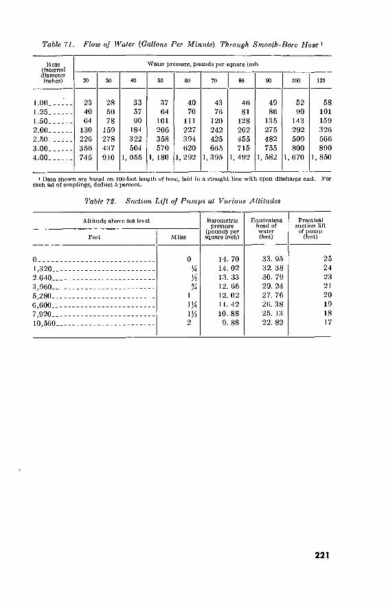
Table 71. Flow of Water (Gallons Per Minute) Through Smooth-Bore Hose 1
Hose (internal diameter inches)
Water pressure, pounds per square inch
20 30 50 60 80 90 125
1.00..
1.25.. 1.50.. 2.00. .
2.50.. 3.00. . 4.00. .
23 40 64
130 226 356 745
28 50 78
159 278 437 910
33 57 90
184 322 504
1, 055
37 64
101 206 358 570
1, 180
40 70
111 227 394 620
1, 292
43 76
120 242 425 665
1, 395
46 81
128 262 455 715
1, 492
49 86
135 275 482 755
1, 582
52 90
143 292 509 800
1, 670
58 101 159 326 566 890
1, 850
1 Data shown are based on 100-foot length of hose, laid in a straight line with open discharge end. For each set of couplings, deduct 5 percent.
Table 72. Suction Lift of Pumps at Various Altitudes
Altitude above sea level
Feet Miles
Barometric pressure
(pounds per square inch)
Equivalent head of water (feet)
Practical suction lift
of pump (feet)
0 1.320.. 2.640- 3,960- 5,280— 6.600.. 7,920- 10,560.
1
1/4 1/
14. 70 14. 02 13. 33 12. 66 12. 02 11. 42 10. 88
9. 88
33. 95 32. 38 30. 79 29. 24 27. 76 26. 38 25. 13 22. 82
25 24 23 21
20 19 18 17
221

222
Table 73. Theoretical Discharge of Nozzles in United States, Gallons Per Minute 1
Head
Psi Feet
10-
15-
20-
25-
30-
35- 40-
45-
50-
55-
60-
65-
70-
75-
80-
85-
90-
95-
100.
23. 1 34. 6 46. 2 57. 7 69. 3 80. 8 92. 4
103. 9 115. 5 127. 0 138. 6 150. 1 161. 7 173. 2 184. 8 196. 3 207. 9 219. 4 230. 9
Velocity of dis- charge
(feet per second)
38. 6 47. 25 54. 55 61. 0 66. 85 72. 2 77. 2 81. 8 86. 25 90. 4 94. 5 98. 3
1Ó2. 1 105. 7 109. 1 112. 5 115. 8 119. 0 122. 0
Diameter of nozzle in inches
Mo
0. 37 . 45 . 52 . 58 . 64 . 69 . 74 . 78 . 83 . 87 . 90 . 94 . 98
1. 01 1. 05 1. 08 1. 11
1. 14 1. 17
1. 48 1. 81 2. 09 2. 34 2. 56 2. 77 2. 96 3. 13 3. 30 3. 46 3. 62 3. 77 3. 91 4. 05 4. 18 4. 31 4. 43 4. 56 4. 67
Mo
3. 32 4. 06 4. 69 5. 25 5. 75 6. 21 6. 64 7. 03 7. 41 7. 77 8. 12 8. 45 8. 78 9. 08 9. 39 9. 67 9. 95
10. 2 10. 05
5. 91 7. 24 8. 35 9. 34
10. 2
11. 1 11. 8 12. 5 13. 2 13. 8 14. 5 15. 1 15. 7 16. 2 16. 7 17. 3 17. 7 18. 2 18. 7
13. 3 16. 3 18. 8 21. 0 23. 0 24. 8 26. 6 28. 2 29. 7 31. 1 32. 5 33. 8 35. 2 36. 4 37. 6 38. 8 39. 9 41. 0 42. 1
23. 6 28. 9 33. 4 37. 3 40. 9 44. 2 47. 3 50. 1 52. 8 55. 3 57. 8 60. 2 62. 5 64. 7 66. 8 68. 9 70. 8 72. 8 74. 7
H
36. 9 45. 2 52. 2 58. 3 63. 9 69. 0 73. 6 78. 2 85. 5 86. 4 90. 4 94. 0 97. 7
101. 0 104. 0 108. 0 111. 0 114. 0 117. 0
53. 1 65. 0 75. 1 84. 0 92. 0 99. 5
106. 0 113. 0 119. 0 125. 0 130. 0 136. 0 141. 0 146. 0 150. 0 155. 0 160. 0 164. 0 168. 0
72. 4 88. 5
102. 0 114. 0 125. 0 135. 0 145. 0 153. 0 162. 0 169. 0 177. 0 184. 0 191. 0 198. 0 205. 0 211. 0 217. 0 223. 0 229. 0
94. 5 116. 0 134. 0 149. 0 164. 0 177. 0 189. 0 200. 0 211. 0
221. 0
231. 0 241. 0 250. 0 259. 0 267. 0 276. 0 284. 0 292. 0 299. 0
The actual quantities will vary from the figures in this table, depending on the shape With smooth-taper nozzles the actual discharge is about 94 percent of the figures given of the nozzle and the size of the pipe at the point where the pressure is determined. in the table above.

Table 74- Maximum Quantities of Water in Gallons Per Minute Which Can Be Pumped Throtigh 100 Feet of Wrought-Iron Pipe at Various Pressures
Pressure Pipe diameter (iuclics)
1M i'A 2K
17 psL- 30 psi- _ 40 psi- - 50 psi.. 60 psi., 75 psL- 100 psi-
3. 2 5. 0 6. 0 6. 5 7. 0 7. 5 9. 0
9. 1 14. 0 16. 0 17. 5 19. 5 22. 0 25. 0
18. 7 28. 0 33. 0 37. 0 40. 0 45. 0 52. 0
33. 5 52. 0 60. 0 70. 0 76. 0 85. 0 99. 0
51. 0 78. 0 90. 0
101. 0 110. 0 123. 0 142. 0
106 160 184 206 226 253 292
200 308 350 390 430 480 558
290 436 504 564 617 690 797
589 885
1, 023 1, 143 1, 252 1, 400 1, 607
223 5335CK:0—oo 15
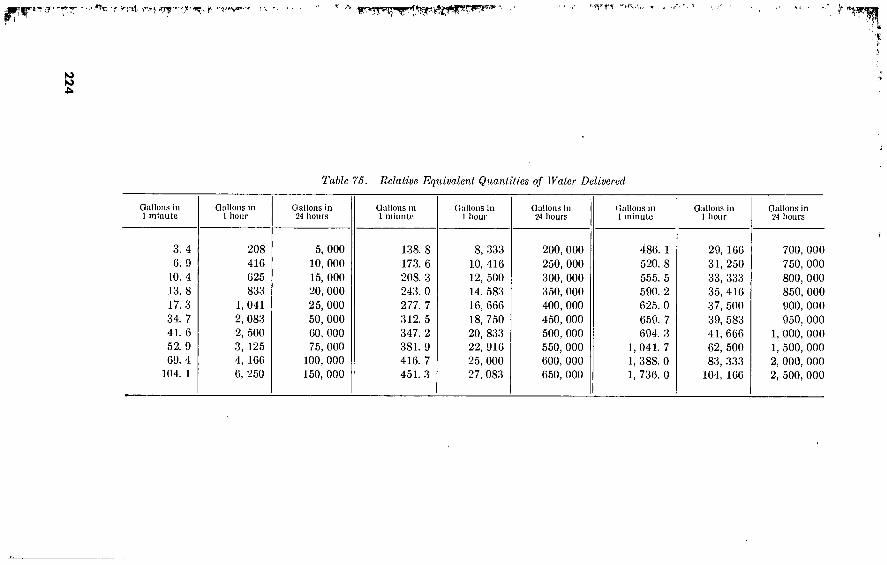
224
ffr '8 T : r-.-i
Table 75. Relative Equivalent Quantities of Water Delivered
Gallons in 1 minute
3. 4
6. 9
10. 4
13. 8
17. 3
34. 7
41. 6
52. 9
69. 4 104. 1
Gallons in 1 hour
208
416
025
833
1, 041 2, 083
2, 500
3, 125 4, 166
6, 250
Gallons in 24 hours
5, 000
10, 000 15, 000 20, 000
25, 000
50, 000
60, 000
75, 000 100, 000
150, 000
Gallons in 1 minute
138. 8
173. 6
208. 3
243. 0
277. 7
312. 5
347. 2
381. 9
416. 7 451. 3
Gallons In 1 hour
8, 333
10, 416 12, 500
14, 583
16, 666
18, 750
20, 833 22, 916
25, 000
27, 083
Gallons in 24 hours
200, 000
250, 000
300, 000
350, 000
400, 000
450, 000
500, 000
550, 000
600, 000
650, 000
Gallons in 1 minute
486. 1
520. 8
555. 5
590. 2
625. 0
659. 7 694. 3
1, 041. 7
1, 388. 0
1, 736. 0
Gallons in 1 hour
29, 166
31, 250
33, 333
35, 416
37, 500
39, 583
41, 666 62, 500
83, 333
104, 166
Gallons in 24 hours
700, 000
750, 000
800, 000
850, 000
900, 000
950, 000
1, 000, 000 1, 500, 000 2, 000, 000 2, 500, 000

81. Rate of Flow Equivalents See table 76.
82. Volume and Capacity Equivalents See table 77.
83. Head-Pressure Conversion Factors
The head of water in feet and the resultant static pressure in p.s.i. (pounds per square inch) are related as follows:
Pressurc = head X 0.4331 Head = press ur o X 2.31.
84. Loss of Head in 1 Vfc-lnch Hose For various flows in gallons per minute, the loss of head per hundred
feet of 1%-inch hose is given in figure 35.
LOSS OF HEAD
PER 100 FEET
OF 1 1 /2-1N HOSE
RUBBER SECTION
RUBBER-LINED
CANVAS
(NO KINKS)
GALLONS PER MINUTE
Figure 85. Loss of head in l}i-inch hose.
225

Table 76. Rale of Flow Equivalents
Units Cubic feet per second
Cubic feet per minute
U.S. gallons per minute
U.S. gallons per 24 hr.
1 cubic foot per second equals
1 cubic foot per minute equals
1 U.S. gallon per minute equals
1 U.S. gallon per 24 hours equals
1 British Imperial gallon per minute equals
1 liter per minute equals 1 acre-foot per hour equals. 1 acre-foot per 24 hours
equals
1. 0
0. 02
0. 002
1. 55X10-«
0. 003 0. 0006
12. 1
0. 50
60. 0
1. 0
0. 13
9. 28X10-
0. 16 0. 03
726. 0
30. 25
448. 83
7. 48
1. 0
0. 0007
1. 20 0. 26
5, 430. 86
226. 2
646, 317. 0
10, 771. 9
1, 440. 0
1. 0
1, 729. 37 380. 42
7, 820, 434. 0
325, 851. 0
Units
1 cubic foot per second equals ^
1 cubic foot per minute equals
1 U.S. gallon per minute equals
1 U.S. gallon per 24 hours equals
1 British Imperial gallon per minute equals
1 liter per minute equals 1 acre-foot per hour equals. 1 acre-foot per 24 hours
equals
British Imperial
gallons per minute
373. 3
6. 23
0. 83
0. 000
1. 0 0. 22
4, 522. 13
188. 42
Liters per minute
1, 698. 98
28. 32
3. 78533
0. 003
4. 55 1. 0
20, 557. 6
856. 57
Acre-feet per hour
0. 083
0. 001
0. 0001841
1. 28X10-
0. 0002 4. 86X10-6 1. 0
0. 04
Acre-feet per 24 hr.
1. 98
0. 03
0. 0044192
3. 07X10-6
0. 005 0. 001
24. 0
1. 0
Note. Negative exponents to the number 10 indicate the number of decimal places to the right of the decimal point, i.e.: 10-«=0.000001; 10-3=0.001; 1.55X10-«=0.00000155.
226

Table 77. Volume and Capacity Equivalents
Units U.S. gallons British Imperial gallons Liters
1 U.S. gallon equals.- 1 British Imperial
gallon equals 1 liter equals 1 cubic foot equals 1 cubic inch equals 1 acre-foot equals 1 inch deep on 1 acre
equals 1 inch deep on 1
square mile equals-. 1 meter deep on 1
hectare equals I centimeter deep on
I square meter equals
I pound of water at 39.2° F. equals
1 pound of water at 50° F. equals
1 pound of water at 62° F. equals
1 U.S. gallon per min- ute for 24 hours equals
1 cubic foot per min- ute for 24 hours equals
1. 0
1. 20 0. 26 7. 48 4. 33
325851. 0
27154. 3
17, 378, 743. 0
2, 641, 705. 0
2. 64
0. 02
0. 12
0. 12
1, 440. 0
10, 771. 9
0. 83
1. 0 0. 22 6. 23 3. 6XIO-3
271, 328. 0
22, 610. 6
14, 470, 801. 0
2, 199, 675. 0
2. 20
0. 10
0. 10
0. 10
1, 199. 05
8, 969. 50
3. 78
4. 55 1. 0
28. 32 0. 02
1, 233, 456. 0
102, 788. 0
65, 784, 344. 0
9, 999, 734. 0
10. 0
0. 45
0. 45
0. 45
5, 450. 88
40, 775. 4
See note at end of table.
227

Table 77. Volume and Capacity Equivalents—Continued
Units Cubic feet Cubic inches Acre-feet
1 U.S. gallon equals 1 British Imperial gal-
lon equals 1 liter equals 1 cubic foot equals 1 cubic inch equals 1 acre-foot equals 1 inch deep on 1 acre
equals 1 inch deep on 1 square
mile equals 1 meter deep on 1
hectare equals 1 centimeter deep on 1
square meter equals-- I pound of water at
39.2° F. equals 1 pound of water at 50°
F. equals 1 pound of water at 62°
F. equals 1 U.S. gallon per minute
for 24 hours equals 1 cubic foot per minute
for 24 hours equals
0. 13
0. 16 0. 03 1. 0
5. 79X10 43, 560. 0
3, 630. 0
2, 323, 200. 0
353, 145. 0
0. 35
0. 02
0. 02
0. 02
192. 5
1. 440. 0
231. 0
277. 42 61. 02
1, 728. 0 1. 0
75, 271, 680. 0
6, 272, 640. 0
4, 014, 489, 600. 0
610, 233, 780. 0
610. 23
27. 68
27. 69
27. 71
332, 640. 0
2, 488, 320. 0
3. 07X10-«
3. 69X10-« 8. 11X10-7
2. 296X10-« 1. 33X10-8 1. 0
0. 08
53. 33
8. 10708
8. 11X10-«
3. 69X10-7
3. 68X10-7
3. 68X10-7
0. 004
0. 03
Note. Negative exponents to decimal point, i.e.: 10-fl=0.000001
the number 10 indicate the number of decimal places to the right of the ; 10-3=0.001; 1.55X10-«=0.00000153.
85. Vertical Cylindrical Tank Capacities Capacities per foot of depth for vertical cylindrical tanks 1 foot to
100 feet in diameter are shown in table 78. Capacities per inch of depth may be computed by dividing the values shown by 12.
86. Chemicals Used to Coagulate or Adjust Alkalinity of Water See table 79.
87. Water Supply and Distribution Systems a. Function. A water system consists of a well, spring, river, lake,
reservoir, or other water source; the treatment plant, pump, ground or elevated storage tanks, supply lines, or other production and treat- ment facilities; and the distribution lines which convey the approved water to the various outlets.
b. Description. (1) Basic systems. There are three basic types of water supply
and distribution systems. (a) Gravity flow, where the source is at sufficient elevation
above the outlets to transport the water without pumping.
228

Table 78. Vertical Cylindrical Tank Capacities
Diameter
1' 0'
1' ]'
1' 2'
1' 3'
1' 4" 1' 5" 1' 6”
1' 7"
1' 8”
1' 9” 1' 10"
1' 11"
2'
2' 1'
2' 2'
2' 3'
2' 4' 2' 5' 2' 6'
2' 7'
2' 8"
2' 9" 2' 10"
2' 11"
3' 3' 1" 3' 2" 3' 3"
3' 3' 3' 3'
3' 8" 3' 9" 3' 10" 3' 11"
4' 4' 1' 4' 2' 4' 3'
Cu ft per 1' of depth
0. 785 0. 922 1. 069 1. 227
1. 396 1. 576 1. 767 1. 969
2. 182 2. 405 2. 640 2. 885
3. 142 3. 409 3. 687 3. 976
4. 276 4. 587 4. 909 5. 241
5. 585 5. 940 6. 305 6. 681
7. 069 7. 467 7. 867 8. 296
8. 727 9. 168 9. 621
10. 08
10. 56 11. 04 11. 54 12. 05
12. 57 13. 10 13. 64 14. 19
XJ.S. gallons per of depth
5. 87 6. 89 8. 00 9. 18
10. 44 11. 79 13. 22 14. 73
16. 32 17. 99 19. 75 21. 58
23. 50 25. 50 27. 58 29. 74
31. 99 34. 31 36. 72 39. 21
41. 78 44. 43 47. 16 49. 98
52. 88 55. 86 58. 92 62. 06
65. 28 68. 58 71. 97 75. 44
78. 99 82. 62 86. 33 90. 13
94. 00 97. 96
102. 0 106. 1
Diameter
4' 4" 4' 5" 4' 6" 4' 7"
4' 8'' 4' 9';
4' 10' 4' 11''
5' 5' 3" 5' 6" 5' 9"
6'
6' 3' 6' 6'
6' 9'
7' 7' 3' 7' 6' 7' 9'
8'
8' 3' 8' 6'
8' 9'
9' 9' 3' 9' 6' 9' 9'
10'
10' 6'
11'
11' 6'
6'
12'
12'
13' 13' 6
14' 14' 15' 15' 6
6"
Cu ft per 1' of depth
14. 75 15. 32 15. 90 16. 50
17. 10 17. 72 18. 35 18. 99
19. 63 21. 65 23. 76 25. 97
28. 27 30. 68 33. 18 35. 78
38. 48 41. 28 44. 18 47. 17
50. 27 53. 46 56. 75 60. 13
63. 62 67. 62 70. 88 74. 66
78. 54 86. 59 95. 03 103. 9
113. 1 122. 7 132. 7 143. 1
153. 9 165. 1 176. 7 188. 7
U.S. gallons per 1' of depth
110. 3 114. 6 119. 0 123. 4
128. 0 132. 6 137. 3 142. 0
140. 9 161. 9 177. 7 94. 3
211. 5 229. 5 248. 2 267. 7
287. 9 308. 8 330. 5 352. 9
376. 0 399. 9 424. 5 449. 8
475. 9 502. 7 530. 2 558. 5
587. 5 647. 7 710. 9 777. 0
846. 0 918. 0 992. 9
1, 071. 0
1, 152. 0 1, 235. 0 1, 322. 0 1, 412. 0
229

Table 78. Vertical Cylindrical Tank Capacities—Continued
Diameter
I, f.
k t-
i c ?>■
16' 16' -6" 17' 17' 6"
18' 18' 6' 19' 19' 6'
20'
20' 6'
21'
21' 6'
22'
22' 6'
23' 23' 6'
24' 24' 6" 25' 25' 6"
26' 26' 6' 27' 27' 6''
28' 28' 6' 29' 29' 6'
30' 31' 32' 33'
34' 35' 36' 37'
Cu ft per 1' of depth
201. 1 213. 8 227. 0 240. 5
254. 5 268. 8 283. 5 298. 6
314. 2 330. 1 346. 4 363. 1
380. 1 397. 6 415. 5 433. 7
452. 4 471. 4 490. 9 510. 7
530. 9 551. 5 572. 6 594. 0
615. 8 637. 9 660. 5 683. 5
706. 9 754. 8 804. 3 855. 3
907. 9 962. 1
1, 018. 0 1, 075. 0
U.S. gallons per 1' of depth
1, 504. 0 1, 600. 0 1, 698. 0 1, 799. 0
1, 904. 0 2, Oil. 0 2, 121. 0 2, 234. 0
2, 350. 0 2, 469. 0 2, 591. 0 2, 716. 0
2, 844. 0 2, 947. 0 3, 108. 0 3, 245. 0
3, 384. 0 3, 527. 0 3, 672. 0 3, 820. 0
3, 972. 0 4, 126. 0 4, 283. 0 4, 443. 0
4, 606. 0 4, 772. 0 4, 941. 0 5, 113. 0
5, 288. 0 5, 646. 0 6, 016. 0 6, 398. 0
6, 792. 0 7, 197. 0 7, 616. 0 8, 043. 0
Diameter
38' 39' 40' 41'
42' 43' 44' 45'
46' 47' 48' 49'
50' 52' 54' 56'
58' 60' 62' 64'
66'
68'
70' 72'
74' 76' 78' 80' 82'
84' 86'
88'
90'
92' 94' 96' 98'
100'
Cu ft per 1' of depth
1, 134. 0 1, 195. 0 1, 257. 0 1, 320. 0
1, 385. 0 1, 452. 0 1, 521. 0 1, 590. 0
1, 662. 0 1, 735. 0 1, 810. 0 1, 886. 0
1, 964. 0 2, 124. 0 2, 290. 0 2, 463. 0
2, 642. 0 2, 827. 0 3, 019. 0 3, 217. 0
3, 421. 0 3, 632. 0 3, 488. 0 4, 072. 0
4, 301. 0 4, 536. 0 4, 778. 0 5, 027. 0 5, 281. 0
5, 542. 0 5, 809. 0 6, 082. 0 6, 362. 0
6, 648. 0 6, 940. 0 7, 238. 0 7, 543. 0 7. 854. 0
U.S. gallons per 1' of depth
8, 483. 0 8, 940. 0 9, 404. 0 9, 876. 0
10, 360. 0 10, 860. 0 11, 370. 0 11, 900. 0
12, 430. 0 12, 980. 0 13, 540. 0 14, 110. 0
14, 690. 0 14, 890. 0 17, 130. 0 18, 420. 0
19, 760. 0 21, 150. 0 22, 380. 0 24, 060. 0
25, 590. 0 27, 170. 0 28, 790. 0 30, 450. 0
32, 170. 0 33, 930. 0 35, 740. 0 37, 600. 0 39, 500. 0
41, 540. 0 43, 450. 0 45, 490. 0 47, 590. 0
49, 720. 0 51, 920. 0 54, 140. 0 56, 420. 0 58, 750. 0
230
L.
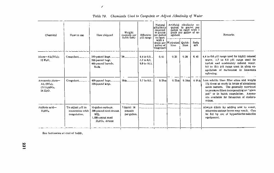
y
Table 79. Chemicals Used lo Coagulate or Adjust Alkalinity of Water
Chemical How to use How shipped Weight
(pounds per cubic foot)
Effective pH range
Natural alkalinity required in grains
per gallon to react with 1
grain per gallon of
coagulant
Artificial alkalinity re- quired in grains per gallon to react with 1 grain per gallon of co- agulant
Hydrated lime
Quick- lime
Soda ash
Remarks
Alum—Al2(SO<)3 18 IUO.
Coagulant.. 100-pound bags
200-pound bags.
400-pound barrels. Bulk.
39. 4.4 to 6.0.. 5.7 to 8.0.
9.0 to 10.5.
0.45 0.35 0.28 0.48 4.4 to 6.0 pH range used for highly colored water. 5.7 to 8.0 pH range used for turbid and moderately colored water.
9.0 to 10.5 pH range used in alum co- agulation of carbonates in lime-soda softening.
Ammonia alum-
Ah (SOah
(NIIO2SO4. 24 H2O.
Coagulant.. 400-pound bags.. 100-pound kegs.
39±_ 5.7 to 8.0. 0.29± 0.23± 0.18± 0. 31±
Sulfuric acid—
H2SO4.
Less soluble than filter alum and weighs 1}£ times as much In terms of aluminum oxide content. Use generally restricted
to pressure filters incorporating an “alum pot” or in batch coagulation. Ammo-
nia available for formation of choloro- mines.
To adjust pH in
connection with
coagulation.
10-gallon carboys.
500-pound steel drums.
93%. 1,500-pound steel
II2SO4. drums
Liquid: 18
pounds per gallon.
Always dilute by adding acid to water,
otherwise serious burns may result. Can be fed by use of hypochlorlte-solutibn equipment.
See footnotes at end of table.
to 04

232
F?'”' . '* ■T” ‘c *»» ce»^*» > < , ' \ 1 - " 'h 'J $f^!FWf|^W9'‘ 1 ' '• * ' y1, ’ ^ ^ ' ' ' ' ’’V^ ' ' '' ' 1 ' ‘< l . ‘ ; ‘ ► W,V:^
Table 79. Chemicals Used to Coagulate or Adjust Alkalinity of Water—Continued
Chemical ITow to use How shipped Weight
(pounds per cubic foot)
Effective pH range
Natural alkalinity required in grains per gallon
to react with 1
grain per gallon of
coagulant
Artificial alkalinity re- quired in grains per gallon to react with L grain per gallon of co- agulant
Hydrated lime
Quick- lime
Soda ash
Kcmarks
Sodium aluminate- NazAhO*.
Coagulant. Solid: 108-pound thin-
steel drums. 405-pound thin-
steel drums.
100-pound bags.
Liquid: 32% Na2Al204—
steel drums
10% NaOH.
58±. 6.0 to 7.5 (with alum).
Used with alum to assist In the coagulation
of cold water. Also used with alum to coagulate alkaline waters, such as with water softening. Supplies alkali as well as aluminum. Commercial grade contains
55% aluminum oxide and 35% combined soda plus 6% excess caustic soda.
Copperas (ferrous
sulfate)—FeSO*.
Coagulant..
Chlorinated copperas.
Coagulant..
100-pound bags 200-pound bags.
400-pound barrels.
Bulk.
46±_. 8.5 to 11.0. 0.27 (0
See copperas. SccCopperas 0.85 *0.65 0.52 0) Chlorine added to copperas. One pound
of chlorine required for each 7.8 pounds of copperas used.
Ferric sulfate-
Fe2(S04)3.
Coagulant. 200-pound bags
400-pound wooden barrels.
0 78 0 58 0. 40 (0 If dry-feet machine is used, must have solution pot feeding two parts water to
each part of ferric sulfate. Used with lime for iron and manganese removal.

233
Ferric chloride—
FeCls.
Soda ash—NajCOs-.
Hydrated lime— Ca(OH)a.
Quick lime—CaO..
Coagulant.
To adjust pH, aid coagulation, or remove perma- nent hardness.
To adjust pH, aid coagulation, or remove carbo- nate hardness.
To adjust pH, aid coagulation, or remove carbo- nate hardness.
Liquid: 12-gallon carboys.
42%. 8,000-gallon
rubber-lined tank cars. 42%.
Crystals: 55-gallon hardwood
barrels, each containing 435 pounds. 60%.
Anhydrous: 100 one pound
bags per steel drum. 95% ferric chloride.
100-pound bags.
200-pound bags. 400-pound barrels.
Bulk.
50-pound paper bags.
Wooden barrels, metal drums, water proof bags.
Bulk.
3.5
63..
50..
65..
Pulverised lime- stone—94% CaCOj.
Adjust pH and/or aid coagulation.
80-pound bags or bulk 100..
to 9.5.. 0.92 0. 72 0. 58 0) Very corrosive. Rubberlined equipment must be used. Use with lime for iron and manganese removal. Use with pul- verized limestone to coagulate turbid and colored waters.
Readily soluble and non-corrosive to wrought-iron or lead piping. May be used to prevent corrosion when hardness of water exceeds about 40 quarts per million.
Only slightly soluble and thus is fed as a suspension. Cheaper and more effective than soda ash. Used to prevent corro- sion irrespective of hardness of water.
Must be slaked before used. Somewhat cheaper and more effective than hy- drated lime, but difficulty of handling limits its used to large plants.
May be added as batch or fed with dry or slurry feeders. Particularly useful in solids, contact readers.
i Not normally used. a See ferric coagulants.

(b) Direct pumping, where water from the source is pumped directly into the system with or without a pressure tank to absorb differences between pumping and usage rates.
(c) A combination of gravity and pumping, where water from the source is pumped to an elevated storage tank and from there distributed to the outlets by gravity.
(2) Pipes. (a) Classification. The network of pipes should be arranged
so that large primary mains feed smaller secondary pipes. Mains carry water from the source to the service pipes. Service pipes carry water from the main to the building.
(b) Arrangement. A distribution system is constructed either as a dead-end system or as a loop system. In a dead-end system a single distribution main runs from the pump or elevated storage tank to the various outlets. In a loop system the distribution main forms a single loop or a series of loops with both ends connected to the pump or elevated storage tank. The advantage of a dead-end system is the economy in length of main. The advantages of a loop system are the equal delivery capacity with smaller mains, a more uniform pressure, and the ability to make repairs with a minimum of outlets deacti- vated. Complete loop systems are seldom used in field installations.
(c) Design and construction. The design of a distribution system is based on the known requirements and physical data obtained from reconnaissance, surveys, and maps. TM 5-302 includes standard layouts.
88. Equipment for Purification and Treatment
a. Standard Sets. (1) The following sets are now standard:
(a) Water purification equipment set, trailer mounted, dia- tomite filter, 600 gph; primarily for airborne use.
(b) ' Water purification equipment set, truck mounted, dia- tomite filter, 1,500 gph; primarily for use with combat units.
(c) Water purification equipment set, truck mounted, dia- tomite filter, 3,000 gph.
(d) Water purification equipment set, base mounted, diatomite filter, 3,000 gph; for use as stationary equipment under Arctic conditions, and also in non-Arctic areas.
(2) A water purification plant with a capacity of 10,000 gph is under development at ERDL, and it is expected will shortly become standard. It incorporates coagulation and rapid sand filtration apparatus.
234

b. Locally Designed Facilities. If standard water purification sets are not available or do not meet local requirements, other standard issue pumps are used with issue or locally designed and constructed storage and treatment facilities. The usual storage requirement is for an aggregate of half a day’s supply in reservoirs and/or tanks, normally with at least one tank elevated to insure adequate head. Treatment facilities depend upon the type and quantity of water but normally include the items shown in the typical flow diagram, figure 36.
c. Typical Equipment for Storage and Treatment. (1) Pumps.
(а) Centrifugal self priming pumps. The following are now standard: 10 gpm at 80 ft. head, electric driven. 50 gpm at 70 ft. head, electric driven. 50 gpm at 25 ft. head, gasoline driven. 115 gpm at 25 ft. head, gasoline driven. 166 gpm at 25 ft. head, gasoline driven. 200 gpm at 300 ft. head, gasoline driven. 500 gpm at 30 ft. head, gasoline driven. 1,500 gpm at 60 ft. head, gasoline driven. 2,100 gpm at 25 ft. head, gasoline driven.
(б) Helical rotor type pumps. The standard type is a deep well pump, 50 gpm at 250 ft. head, gasoline driven.
(c) Turbine type pumps. The standard type is a deep well pump, 200 gpm at 200 ft. head, gasoline or electric driven.
(d) Diaphragm type pumps. The standard type, preferred for abrasive material, delivers 200 gpm at 10 ft. head, gaso- line driven.
(2) Storage tanks. Standard vertical cylindrical bolted steel tanks, low type, for the storage of water or petroleum products, are issued in capacities of 4,200, 10,500, 21,000, and 42,000 gallons. For the high type the standard tank has a capacity of 126,000 gallons. Standard rubber coated fabric tanks are issued in capacities of 500, 1,500, and 3,000 gallons.
(3) Plain sedimentation tanks or basins. (To remove sediment from raw water not coagulated.) A typical shape is shown in figure 37. To determine the size needed, assume a depth between 5 and 10 feet, plus 1 foot (6" freeboard and 6" allowance for sludge). Find the time (minutes)' required for 70% of the solids to settle from a sample of the water in a bottle. Tank size is then computed from:
(a) Retention time Effective tank Settling time in (minutes water depth (ft.) bottle (min.) must stay in tank) Depth of water sample in bottle (ft.)
235

236
"rp. , f 'r- « 1 v>. 't; -■’ ^
■^J
CHEMICAL TANK
\ MIXING
BASIN
fQLídQ
COAGULANTS ENTER HERE
RAW WATER FROM PUMPING
STATION OR RESERVOIR
CHLORINATOR WASH
WATER
L À i ^ru M
SEDIMENTATION FILTER BASIN
<C /2
□uo SLUDGE DRAIN
PUMP
TO DISTRIBUTION
MAINS OR RESERVOIR
Figure 86. Flow diagram for typical water treatment plant.
\

(b) Tank capacity _Retention time (min) X requiredflow (gpm) (cu. ft.) 7.5 (gal per cu. ft.)
(c) Tank length (ft.)=Retention time (min) Xvelocity of flow (fpm) Desirable velocities are between 0.6 and 1.0 (fpm).
Tankwidth_ Tank capacity (cu. ft.) (ft.) Tank depth (effective) (ft.) X tank length (ft.)
(e) Example: Given: Required flow, 500 gpm; settling time in a bottle 6 inches deep, 5 min.; effective tank depth assumed at 5 feet; velocity of flow assumed at 0.9 fpm. Solution:
5X5 Retention time=—r—=50 min.
.5
rp , 50X500 , lank capacity =—^—=3,333 cu. ft.
Tank length =50X0.9=45 ft.
Tank width =-^—rr = 14.8 ft. (Use 15 ft.)
(4) Chemical-mixing and coagulation tanks. If the water is easily coagulated, these are omitted and coagulants are added at the suction side of the pump supplying a floe sedimentation tank. If a coagulation tank is needed, its capacity should be at least 2 to 4 hours of the required flow rate; e.g., 5,000 gallons for a flow rate of 500 gpm. One type of coagulant tank with auxiliary equipment is shown as figure 38.
(5) Floe sedimentation tanks. These are similar to the plain sedimentation tanks described in (3) above and the size is determined in the same way, based on the settling time for a bottle of the coagulated water as it reaches the tank. The size is usually smaller, due to more rapid settling after coagulation. A velocity of flow of 1.0 fpm is usually satis- factory.
(6) Filters. For military installations too large to be served by the standard issue filters, a rapid sand filter is usually satis- factory. These filters are described as follows:
(a) Types and capacity. Rapid sand filters are either gravity or pressure types, as shown in figures 39 and 40. Gravity filters are open steel tanks as shown in figure 41 or may be rectangular reinforced concrete boxes, operated as
-shown in figure 41. Pressure filters are inclosed vessels in which water is pumped through the bed of filter sand. Gravity filters are best for large installations; pressure
237

238
1 l1 ! 1 || I f , ,1 * '-í 7’ X-vr1* - ■ " :
INLET OF RAW WATER OR WATER FROM COAGULANT
MIXING CHAMBER
BAFFLE TO EXCLUDE FLOATING MATERIAL FROM OUTLET
SETTLING BASIN
* V l<
‘ f.
SLOPE TO DRAIN
il SCREEN OR STRAINER
\ m. î;:I
ÍTTTTT
SLUDGE DRAINJ:
Figure 37, Settling tank for either plain or coagulated sedimentation.
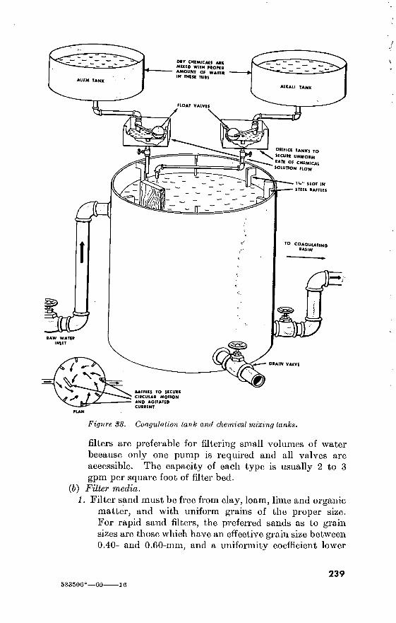
f«ÜÍi fer- 0«r CHEMICAIS ARC MIXED WITH PROPER AMOUNT OP WATER IN THESE TUBS
ALUM TANK
ALKALI TANK
HOAT VALVES
ORIFICE TANKS TO
SECURE UNIFORM
•ATE OF CHEMICAL
SOLUTION FLOW
X
IV' SLOT IN
STEEL BAFFLES
•O COAGULATING
BASIN
RAW WATER INLET äS;
DRAIN VALVE
m BAFFLES TO SECURE
CIRCULAR MOTION
AND AGITATED
CURRENT
Figure 38. Coagulation tank and chemical mixing tanks.
filters are preferable for filtering small volumes of water because only one pump is required and all valves are accessible. The capacity of each type is usually 2 to 3 gpm per square foot of filter bed.
(b) Filter media. 1. Filter sand must be free from clay, loam, lime and organic
matter, and with uniform grains of the proper size. For rapid sand filters, the preferred sands as to grain sizes are those which have an effective grain size between 0.40- and 0.60-mm, and a uniformity coefficient lower
533500°—co 10
239

240
WASH WATER
T~ 6" FREEBOARD
4- át- rjy
HEADER
& WASH WATER
WASTE
FILTERED WATER
- OUTFLOW AND
BACKWASH INFLOW
COAGULANT-TREATED-
WATER INFLOW
UNDERDRAINS SPACED P" TO *P*''
AND SIOUED OR PERFORATED ON BOTTOMS
4' WATER DEPTH
3' OF 0 4-TO O.t-MM SAND
6" OF GRAVEL
4“ OF V-V' GRAVEL
4" OF l"-*" GRAVEL
4" OF 1<>V' GRAVEL
1V>" OF I h" GRAVEL BELOW PIPE
Figure 39. Typical gravity filler, showing relationship of filler medium, gravel, and underdrain.

UNFILTERED WATER
BACKWASH INLET VALVE
BACKWASH
OUTLET VALVE
AIR BLEEDER
INLET PORT
'' WASTE
WASH WATER
[FILTER SAND] WiSS® 1 'ír’-i CX
GRADED GRAVEL I
„ a g <3^ UNDERDRAINAGE SYSTEM
•9 -
• • •
FILTERED WATER
Figure 40. Pressure-lype rapid sand filter.
than 1.75. Effective grain size is that grain size in a given sample which is larger than 10 percent of, but smaller than 90 percent of, the grains in the sample. The uniformity coefficient is the grain size such that 60 percent of the grains are smaller, divided by the effective size. Thus if 60 percent of a sample passes a sieve with 0.42-mm openings and 10 percent passes a sieve with 0.15-mm openings, the uniformity coefficient is 0.42 -M).15, or 2.8.
2. Anthrafilt, a product made from freshly mined anthracite coal, is an acceptable substitute.
241

„ WASH-WATER TANK
WATER LEVEL,
FILTERING
WATER LEVEL
WASHING .V"
SETTLING BASIN
SAND
— 24" JO ao-
IB"TO 24" X&Mr. CONTROLLER GRAVEL
;V0 STS * « +4 \UNDIRDRAIN
SYSTEM
3 FILTERED-WATER STORAGE
DRA N
24" FREEBOARD
NOTE:
To operate filter, open volves 1 and 2. To backwash, close valve 1; after water already in filter flows down to top of wash-water trough, close valve 2 and open valve' 3 and 4. To run water from filter to waste, close valves 2, 3 and 4 open valves 1 and 5.
Figure 4Î. Operating a gravity-type rapid sand filter»
8. Filter gravel, composed of hard, durable pebbles, is usually placed in graded layers, coarsest at the bottom, as follows:
Passing screen Retained on screen Depth of layer Layer No. opening (tuches) opening (inches) (inches)
1 2}i iy2 4 2 IH 3A 6 3 % Vz 4 4 Vz Vi 4 5 % Vs 4
(c) Typical operating criteria. 1. Washing is needed when the loss-of-head gage, figure 42,
shows a loss of 7 to 9 feet or after a filter run of 100 hours. (Sudden decrease in loss-of-head usually means cracks in the filter bed surface. These require prompt correction or a backwash, to insure satisfactory filtering.)
242

2. Best wash-water velocity is between 15 and 20 gpm per square foot of filter surface. This is equivalent to a rise in water level of between 2 feet and 2.5 feet 4 inches per
. minute, with valve 4 (figure 41) in operating position. Normally the desirable velocity is the highest velocity which is attainable without loss of filter sand.
(7) Hypochlorinators. (a) The standard portable pumping and hypochlorinator unit,
50 gpm, pumps water from a source, applies a hypochlorite solution, and delivers 50 gpm of chlorinated water against a head of 50 feet, of which 15 feet may be suction. It is useful for small installations.
(b) The standard portable automatic hypochlorinator, 2 to 100 gpm, when installed on a bypass connection assembly on a 4-, 6-, or 8-inch main, chlorinates flows ranging from 2 to 400 gpm.
LOSS-OF HEAD GAGE
CALIBRATED IN FEET \
y WATER LEVEL, FlITERING^ FLOAT
©
FLOAT
FROM SETTLING BASIN
FLOAT TUBE A
/.y.;-;:’SAND-. ’ '-V FLOAT TUBE B
GRAVEL
UNDERDRAWN
SYSTEM
A.V* 'A ^ V V -»' a *
f .’A * *, A A .-A ' 4 " 4 ■l3- V P
THROUGH CONTROLLER
TO FILTERED-WATER STORAGE
Figure Loss-of-head measurement.
243

JS».'
PETCOCK ^
FLOAT
BRASS TUBING
» +<#■
RUBBER TUBING
SUCTION LINE TO PUMP
PETCOCK TO PREVENT AIR INTAKE INTO SUCTION LINE
NOTE THIS TUBE MUST NOT RUN FULL OR A VACUUM WILL FORM INCREASING FLOW.
DRUM OR WOOD BARREL
Figure 43. Improvised constant-flow chlorinating apparatus.
(c) Commercial type chlorinators may be available in existing installations. These usually require the use of liquid chlorine in cylinders.
{d) If neither standard nor commercial chlorinators are avail- able, constant-flow apparatus is improvised as shown in figure 43, and controlled manually.
89. Expedient Distillation a. When necessary, expedient stills are built to produce potable
water from a source of heat, a method of forming and collecting steam, and some kind of condenser. The efficiency of an expedient still
244
> t. -

depends on the materials available and the ingenuity of the designer. In expedient distillation, sufficient vapor-separating space is provided to prevent carryover of salt with the steam. Care is taken to avoid getting salt in the distillate through the expedient means used to condense the steam. To avoid endangering personnel by the building up of excessive steam pressure, never put a valve in the distillate liiie.
b. Figure 44 illustrates an expedient still with water-cooled condenser.
WATER-LEVEL
CONTROL VALVE
2" x V<" BUSHING
BOILER
rA.
FEED VALVE
INSTALL NEW BARREL
WHEN NECESSARY TO REMOVE SCALE
DISTILLATE OUTLET
W PIPE
rr^TTTT
DRAIN VALVE
CONDENSER '
1W OR 2" PIPE
VALVE'
COOLING-WATER COOLING-WATER INLET
OUTLET
Figure JtJf. Expedient still, water-cooled condenser.
90. Hypochlorination Units See table 80.
91. Water Demands a. General. Delivery of water through a distribution system is
continuous and in sufficient quantity to meet the maximum rate of demand (peak demand).
b. Peak Demand for a System. The size of a water main serving an area depends on the total peak demand for that area. Service con- nections and mains are made large enough to deliver the total peak demand under the available pressure. Figures 45 and 46 give the peak demand, in gallons per minute, in terms of the number of fixture units on a main. Figure 45 (1) is for a system with 240 fixture units or less; figure 45 (2), for a system with more than 240.
c. Fire-Protection Demand. In temporary installations it may be impracticable to construct distribution systems large enough to meet the demand of firefighting equipment. In such cases it is best to provide ground storage tanks or sumps, so located that any building can be reached with not over 1,000 feet of hose. Water is pumped by fire pumper trucks or skid-mounted pumps.
245

Table 80. Hypochlorination Units
Unit Operation Capabilities
Hypochlorination unit, automatic, poi1 table.
Water-pressure operated.
Virtually automatic, requiring only 1 operator under all conditions.
Installed in 2" pipe or hose, it chlorinates water pumped at rates from 2 to 100 gpm. In- stalled on a bypass from 4- or 6- inch main, it chlorinates flows from 2 to 400 gpm. When set for maximum flows expected, the unit proportions the solution for flows down to one-tenth the maximum.
Pumping and hypo- chlorination unit, portable.
Gasoline engine coupled to a cen- trifugal pump with a belt-driven hypochlorinator.
This unit pumps and treats water which requires chlorination only. It delivers 55 gpm of chorinated water against a total head of 50 feet, 15 feet of which may be suction.
Length, Width, Height, Weight
L = 25'' W=18^" H=26''
Wt= 165#
L=31" W=25" 11 = 38"
Wt = 285#
Remarks
For planning purposes, the chemi- cal requirement is 1 ounce of calcium hypochlorite (70% avail- able chlorine) per 1000 gallons. See TM 5-2032 for details of operation. Requires a minimum continuous water pressure of 10 psi; 5 psi of which is lost to fric- tion. There is a constant small wastage of water from the unit.
See TM 5-295 for details of opera- tion.

100
H 80
D 2
2 oí U ^ 60
2 O J J < O
. 40 Q 2 < 2 u Q
20
0 0 20 40 60 80 100 120 140 160 180 200 220 240
FIXTURE UNITS
CURVE NO. 1 FOR SYSTEM WITH FLUSH VALVES CURVE NO. 2 FOR SYSTEM WITH FLUSH TANKS
Figure 45 (1). Supply-demand curve, for fixtures not exceeding 240.
92. Water Pressures a. Supply Mains and Pumps. Working pressures for the supply
mains vary with the equipment available. The pumps and equipment described in TM 5-350 are designed for maximum pumping pressures of 200 to 400 pounds to the square inch. High pump pressure permits the use of smaller pipe without reducing the supply-main capacity. However, pressure must be multiplied by about 4 to double the capac- ity of a main, whereas doubling the cross-sectional area of the main accomplishes about the same result. It is materially more economical to operate and maintain pumps and pipes at 100 to 150 pounds to the square inch than at higher pressures.
b. Distribution. Pressures in distribution mains are held down—by pressure-reducing valves, if necessary—to avoid exceeding the allow- able pressure at outlets. This allowable pressure is established to minimize faucet leakage, wear and tear on faucets and fixtures, and water-hammer damage. It is usually set at between 20 and 75 pounds to the square inch and as near 20 pounds to the square inch as will
<£
-2-
/
/ -r
v-
:;z::
:z «-
247

500
400
UJ t- 3
CE Ui O. CO Z o
< o cf Z < 2 Ul o
300
200
100
© ¡
i! 500 1,000 1,500 2,000 2,500
FIXTURE UNITS CURVE NO. I FOR SYSTEM WITH FLUSH VALVES CURVE NO. 2 FOR SYSTEM WITH FLUSH TANKS
apeo
Figure 1+B (8). Supply-demand curve, for fixtures in excess of 240 units.
prevent outlet pressures from falling below 20 pounds to the square inch at a time of peak demand. A valved bypass around the reducing valve permits any temporary pressure increase needed for firefighting.
c. Characteristics of Pipes. Table 81 gives dimensions, weights, and other data of standard steel and other pipes in ordinary use. See also table 155. For friction losses, see paragraph 93. For compara- tive discharge capacities, see paragraph 95.
93. Friction Losses Friction losses in service connections and distribution mains are
normally based on the use of iron or steel pipe, using the C=120 in the Hazen and Williams formula for temporary camps, and C=100 for permanent camps. The alinement charts in figures 46 and 47 are used for computing friction losses in straight pipes and in valves and fittings.
248
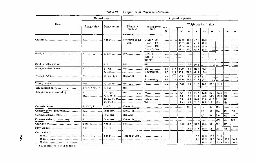
24
9
Table 81. Properties of Pipeline Materials
Item
Cast iron.
Steel, API..
Steel, pipeline tubiriR-
Normal sizes
Length (It.) Diameter (in.)
4 to 84.
Physical properties
Friction i coefl. C
140 (new) to
(old). 100
Working press (psi)
Class A, 50...
Class B, 100.. Class C, 150..
Class D, 200..
1,400 (4")-
1,300 (O'O- 950 (8")---
050.
Weight per lln. ft. (lb.)
19 2
19.2 19.2 19.2
30.0
30.0 30.0 30.0
10.9
42.9 42.9
42.9 42.9
10. 2
12 18 24 36
73.3
73.3 77.9 83 8
48
Steel, seamless or weld..
Wrought iron..
Wood, bonded..
Bitumlnizcd fiber..
Asbestos cement (transite).
Concrete, sewer.
Concrete sewer, reinforced.
Concrete culvert, reinforced.
Concrete culvert, extrastrong.
Clay, sewer..
Clay, culvert.
Corr. metal:
16 ga 14 ga 12 ga
YA, VA, 2.
4, 0, 8.... 140.. Std
Extrastrong. 1.1
1.5 3.7
5.0
10.9 15 0
19.2 28.6
28.8 43.4
50.7 65.4
%, 2, 4, 6, 8... 130 to 140.. Std E.xtrastrong.
1.1
1 5 3.7 5.0
10.9
15.0 19.2 28.6
28.8 43.4
50.7 65.4
6-10.. 4, 6, 8, 12.. 120.. 45. 5.8 8.7 17.7 28.8
8 (4"), 5 (0", S") 4, 6, 8.
2 to 3^
4, 6, 10, 12--. 14, 16, 18, 20. 24 , 30, 36
140.. 50.. 100.
150..
200..
4.7 5.0 6.0 8.4
7.6 7.8
10 7
15.4
11.7 11.9
16.8 23.7
19.8 27.6 38.6
49.6
35.9 58.'2
81.2
112
55.5 99.3
141
199
126 211
318
435
2, 2 5, 3, 4. 4 to 24. 130 to 140. 25 35 60 120 225
130 to 140.. 100 450
100 520
3. 130 to 140.,
2, 2.5, 3.. 4 to 36.. 8.0
2, 3.. 15.5
23.0
24.0
43.5 96.0
55.5 116
320
172
218
520
370
505
8 to 84. Less than 100.. 7.6 9.3
10.8 13.3 18.5
15.8 19 5 27.0
21.0
26.0 35.9
37.9 52.4
50.5 70.0
See footnotes at end of table.

25
0
Table 81. Properties of Pipeline Materials—Con tinned
Item
Cast iron.
Steel, API..
Steel pipeline tubing..
Steel, seamless or weld..
Wrought iron..
Wood, bonded..
Bituminized fiber..
Asbestos cement (Transite).
Physical properties—Continued
Three-edge bearing strength (lb. per ft.)
Concrete, sewer..
Concrete sewer, reinforced.
Concrete culvert reinforced.
Concrete culvert extrastrong.
Clay, sewer..
Clay, culvert.
Corr. metal: 1C ga
14 ga
12 ga
1,740
1,000
1,000
1,420
1,000
2, 000
1,300
1,000
2,000
2, 580
3,690
4,920
1,100
2,000
2,370
3,850 5,100
1,500
1,800
1,200
2, 250
1,750
2,030
1,400
16
2,030
4,140 5,3(30
0,340
2,000
2,200
3,000
2,750
1,700
3,300
21
2, 200
2,400
3,000
2,000
3,830
24
2, 340
4,650 7, 050
8,600
2, 400
2,400
3,000
4,000
2,400
4,400
30
2,980 3,000
6,180
10,450
2,700
3,375
5,000
3,200
5,000
36
3,500 5,400
9, 700
12,300
3,000
4,050
6,000
3,900
6,000
3,200
4,725
7,000
48
3,400
5,400
8,000
Remarks
Moderately corrosion-resistant, brit-
tle. (0.013).
Moderately corrosion-resistant.
(0.012).
Mildly corrosion-resistant, semlflcx-
ible.
Corrosion-resistant ductile. (0.011).
Noncorrosive.
Noncorrosive, semiflexible, also per-
forated In 4" size. (0.010).
Noncorrosive, lightweight, brittle. (0.012).
Noncorrosive, brittle. (0.010-0.015).
Noncorrosive, brittle.
Noncorrosive, brittle.
Noncorrosive, brittle.
Noncorrosive, brittle, Irnperv. (0.015-0.013).
Noncorrosivc, brittle, iraperv.
Semiflexible. (0.021) (0.017-0.019) coated.
i Hazen Williams.
Note. Weights of concrete and corrugated 10", 14", 16", 20", and 30" sizes also
metal pipe in 15", 21", 30", and 42" sizes may be interpolated from data shown. Weights or strengths of asbestos-cement pipe in may be estimated by interpolation.

■'4
AMERICAN CAST IRON PIPE COMPANY
160-
I50-;
140“
I30r
120-
110-
lOO^
SO-
TO-1
.02-
.03-
.04- 05- .06-
.08 -r
.2-
.3-
.4-
.8
2 -
3 4 - 5- 6-
80-i 8- 10-
20
Given: 16* cement lined pipe. Coefficient* 140 Heod Loss 0.5ft. per 1000ft.
Then: Dischorge • 950 gol. per min.
48-1
42-
36-
30-
24-
20 18 •
' 14-
12 •
10-
8-
6-
4 -
3-
20000
10000 , 9000- 8000- 7000- 6000- 5000-
4000-
3000-
2000-
1000 „ 900^
''800- 700- 600-: 500—
400-
300-
200-
100- 90- 80- 70- 60- 50-
40—
30-.
20-i
I0-1
NOMOGRAM FOR CALCULATING PIPE SIZE, DISCHARGE AND HEAD LOSS
Th* abov* nomogram is bosod on tho Willlomt-Hoxon formulo*. Q = .006756 CD' <JH 1‘. Tbe cooHUiont of ctm«nt-lin»d Mono*Cott pip* is 140.
Figure 46. Alinement Chart for calculating pipe size, discharge, and head loss.
1 i.p
251
Dis
char
ge i
n G
allo
ns p
er M
inut
e -

EXAMPlf: DOTTED UNE SHOWS THAT
RESISTANCE OF A 6" STANDARD SHORT RADIUS ELBOW IS EQUIVALENT TO 16' OF 6" STANDARD PIPE.
GLOBE VALVE. OPEN -
\ \ \ GATE VALVE '
<- « CLOSED V4 CLOSED ... Vi CLOSED
r-- FULLY OPEN
I
I - —
NOTE: FOR SUDDEN ENLARGEMENTS OR
CONTRACTIONS. USE THE SMALLER DIA-
METER, d, ON PIPE SIZE SCALE.
— 3000
— 2000
—1000
— 500
48— ' 50
42
ANGLE VALVE, OPEN '
CLOSE-RETURN BEND 'jj- -
STANDARD TEE / THROUGH SIDE OUTUT
r--?V
STANDARD ELBOW OR RUN
OF TEE REDUCED '4
MEDIUM SWEEP ELBOW OR _ j
RUN OF TEE REDUCED V«
LONG-SWEEP ELBOW OR
RUN OF STANDARD TEE ~ ~
j /STANDARD TEE
1/
IP - SQUARE ELBOW
— 100 p
_ J j BORDA ENTRANCE
\ I SUDDEN ENLARGEMENT
L4 d/D = V4 d/D = W
i-Jj , d/D^%
1
I ul. ORDINARY ENTRANCE
1 ¡:^0-
SUDDEN CONTRACTION Ji d/ D = Vi
\ l d/D = VS
— dD = V4
1 - 45’ ELBOW
-300
-200
-50 I
-30 I < ac
-20 5
-0.5
-0.3
-0.2
S 4 VS -
< %
— 0.1 -as
Figure J+7. Friction chart for valves and fittings.
252

94. Fixtures Table 82. Schedule of Fixtures per Branch
%-
VÁ-
Size of branch (inches) Connections allowed
Number
15 27 42
Table 83. Recommended Pipe Sizes for Fixture Branches
Fixture Fixture branch size (inches)
Lavatory Bathtub Kitchen sink, small Kitchen sink, large scullery Laundry trays Shower stall per head Water closets, flush-tank Water closets, flush-valve Pedestal urinals, flush-valve.. Wall type urinals, flush-valve.
% for hot and 'A for hot and 'A for hot and % for hot and 'A for hot and 'A for hot and Ys cold. 1 cold. 1 cold.
cold. cold. cold. cold. cold. cold.
Table 84- Rales of Flow Through Fixtures 1
Fixture Gallons per minute
Number of Fixtures..
Water closets with tanks Urinals with tanks Water closets, flush-valve Urinals, flush-valve Lavatories (based on 1 faucet).. Bathtub (based on 1 faucet) Shower head, vvatersaver Shower head, rain type Kitchen sink, small (per faucet). Kitchen sink, large (per faucet) . Service sink (per faucet) Laundry tray (per faucet) Drinking fountains Hose bibbs, y¿ inch
12 3-1
10,
8 45 25
5 18 8
16 10 14 18 14
3 8
12 10 55 33
8 26 12 24 14 18 24 18 4
11
8 10 15 20 25
26 23
115 75 18 56 24 56 32 40 44 40
7 34
40 34
135 82 24 66 30 70 40 50 52 50
8 40
50 48
150 88 33 90 45 95 54 63 68 63 10 60
66 58
170 94 40
120 55
120 70 91 88 81 12 80
75 65
200 100 48
150 70
150 85
103 no 103
15 100
1 Calculated at 40 psi.
253

95. Comparative Discharge Capacities of Water Pipes
Table 85. Comparative Discharge Capacities of Water Pipes
Size of pipe (inches)
Number of equivalent pipes
m Hi 2«
1__
1/4-
1/- 2_ _
2)2-
1 1. 8 3. 6 6. 6
13 19 36 56 97
1 2 3. 7 7
11 20 31 54
1 1. 8 3. 6 5. 3
10 16 27
1 2 2. 9 5. 5 8
15 ■
1 1. 5 2. 7 4. 3 7
1 1. 9 2. 9 5
1 2 2. 8
1
1. 8
Note. To find number of smaller pipes equal to a larger size, read down from smaller pipe size, across from larger size; read answer at Intersection. Thus, capacity of one 2J.$-inch pipe equals capacity of eight 1-inch pipes.
Section II. SEWERAGE 96. General
The subject of sewerage is dealt with in a general way in TM 5-302 and TM 5-283. Further details are given in TM 5-665 and TM 5-666. Sanitary, aspects of the.problem are discussed an FM .21-10.
97. Quantities of Sewage The quantity of sewage that is disposed of varies with the number
of personnel served and the restrictions placed on the use of water. Flows generally range between 15 and 50 gallons per capita per day, although permanent installations with ample water supplies may use more. The average flow from temporary installations is about 25 gallons per capita per day, and this is increased by 50 gallons for each bed in hospitals. The peak rate of flow for short periods in the day may be three times the average rate. The curve in figure 48 shows the ratio of peak flow to average flow.
98. Stream Flow Required For Dilution The amount of stream flow required for disposal by dilution depends
on the strength and quantity of the sewage, the density and near- ness of the population to the stream bank, and the industrial or domestic use of the stream water below the outfall. A stream over- loaded with sewage develops sludge banks and surface scum, is unsightly, and emits an offensive odor. For streams not used for industrial and domestic water supply below the sewage outfall, table 86 provides a guide in determining the quantity of sewage that may be discharged. This table gives the minimum stream flow required for dilution of raw and treated sewage. If enough water is not
254

5: O 4.0
UJ e> <i CE U > < O
<3 Lü 3.0 Q.
O
O
2.5 c Em □ CE 20 30
POPULATION THOUSANDS
Figure U8. Ratio of peak to average sewage flow.
available for dilution, oxidation ponds, leaching cesspools, or tile distribution fields are used for disposal of surplus sewage, talcing adequate precautions to avoid contamination of the water supply.
Table 86. Minimum Stream Flow Required for Dilution
Type of treatment
None Partial (settling). Complete
Dilution per 1,000 sewage-contributing population
Densely populated areas
20 c.f.s. and over- 12 to 20 c.f.s 6 to 12 c.f.s
Sparsely populated areas
5 c.f.s. and over. 3 to 5 c.f.s. 0 to 3 c.f.s.
99. Sanitary Sewers a. Layout. To avoid deep excavations sewers are located along
natural drainage lines. If possible, they are not laid longitudinally under roadways. Road crossings are kept to a minimum and where less than 4 feet of cover is available the pipe is reinforced by back- filling the lower 2 feet of the trench with low-grade concrete. In light traffic areas, sewers should be covered with at least 2 feet of well-compacted earth. Connections adjoining buildings may need only 1 foot of cover. Manholes are located at each change of direction, size, or slope aud usually are placed at the end of each lateral. On
255
533506'—60 17
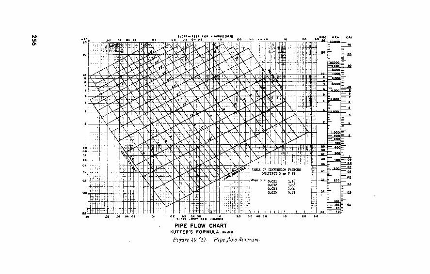
256
BLOPC-FtCT Ptn HUKOMOO*« • F. K
20000 en
10 »0 10 SO *000 OC 0 9 O * 00 OC 09 04 00
tm.
uUUa
DQQ N-V LÔCfi
!SI
II 2 UBO
LOOft
-il — i «¿00
5. &
'ït w fl.QOO —
Loao
s UfififlL
•00 \ roo
W SH S2S
iS ■ag
5 — M 199
»N ■M » S
JLfifi. TABLE OF COKVFRSION FACTCRS
MULTIPLY Q or V BT
SS: 5F‘
\ when 100
Pï o.on 0,012 0.013 0.015
100
i — »0 - QI
to. =
co ao Ùi M 64 00 to 90 40 00
PIPE FLOW CHART KUTTER'S FORMULA (».£,»>
Figure 49 (1). Pipe flow diagram.

"JSMíSSSSí ssuiassi» aaakaaaMaa
04 OI 02 03 II kt
PROPORTIONATE FLOW CHART BV MANNINO'S FORMULA
Figure 49 (2). Proportionate floto chart.
straight sections of sewers, the maximum distance between manholes is 400 feet. Two hundred to three hundred feet spacing is preferable.
b. Size. The size of sewer required to carry a given capacitj7
depends on the slope of the sewer and the resistance to flow caused by the interior surface of the pipe. Pipes less than 4 inches in diameter (on a slope of /fe-inch per foot) are not used, because they clog and require frequent cleaning. Four-inch pipe may be used on house sewers; lateral sewers are 6 inches or more in diameter.
c. Velocity. To prevent the settling out of solids the minimum velocity is 2 feet per second when the sewage flow is at the full ca- pacity of the sewer. However, in unfavorable terrain a velocity of 1.5 fps is satisfactory.
100. Sizes of Sewer Lines
a. Table 87 is based on an assumed peak load of 75 gallons per capita per day. (This is for permanent installations; in a theater of opera- tions, use 25 gallons per day.) Flow is from Kutter’s formula, using n = 0.013. For further information see pipe flow diagram (figure 49 (1)) and proportionate flow chart (fig. 49 (2)).
257

b. The following examples illustrate the use of the pipe flow diagram and the proportionate flow chart as shown in figures 49 (1) and 49 (2).
(1) To determine pipe size: Assume a peak sewage flow of 150 GPM on a 1% slope. Using Figure 49 (1) find intersection of horizontal line from 150 GPM and vertical line of 1%. This falls below a 6" Pipe—the 6" must be used on a trial basis. Then using a 6" pipe on a 1% slope the flow conditions for FULL FLOW can be found; i.e., 230 GPM capacity and 2.5 fps velocity. To find what the actual flow conditions would be, Figure 49 (2) must be used.
(2) To use Proportionate flow chart 49 (2) the Proportionate discharge must be found by:
«ACTUAL QA 150 «FULL FLOW Q„ 230 U-b5
By entering proportionate flow chart at 0.65 construct perpendicular line to discharge curve then horizontal to velocity thence straight down and read proportional velocity
is 1.06—the actual velocity at 150 GPM will be 1.06X
2.5 or 2.7 fps.
Table 87. Sizes of Sewer Lines
Pipe diameter (inches)
2-f.p.s. velocity
Slope (ft. per 100 ft.)
Discharge (g.p.m.)
Population capacity
l.M.p.s. velocity
Slope (ft. per 100 ft.)
Discharge (g.p.m.)
Population capacity
6 8---
10_.
12._
14 >_ 15.. 16 18. . 20 >.
21 _ _
24_ _
0. 63 . 40 . 28 . 21 . 17 . 15 . 14 . 12 . 10 . 09 . 076
176 314 490 707 960
1, 104 1, 260 1, 590 1, 970 2, 160 2, 825
3, 300 6, 000 9, 000
13, 000 18, 000 21, 000 24, 000 30, 000 37, 000 41, 000 54, 000
. 36
. 23
. 16 , 12 095 086 078 067 056 053 044
132 235 368 530 721 828 942
1, 192 1, 472 1, 623 2, 120
2, 500 4, 500 7, 000
10, 000 13, 000 15, 000 18, 000 22, 000 28, 000 31, 000 40, 000
> These sizes are nonstandard sewer sizes.
101. Treatment of Sewage a. Type. If treatment is required, the type of treatment and plant
depend on the quantity and type of sewage, soil conditions, receiving waters, materials and labor available, and the climate. The Army Medical Service is responsible for determining the degree of treatment
258

required before disposal. Partial or complete treatment depends on the conditions controlling the disposal methods.
b. Site and Layout. The main consideration in selecting the treat- ment-plant site is the location of the final receiving ground or diluting water. The treatment plant should be downwind and far enough away from populated areas to avoid odor nuisance. Other factors influencing site selection are the elevation above floodwater level and the ground slope for gravity operation. Unless there is a 10- to 15-foot drop to provide gravity flow through complete treatment plants, the sewage is pumped. All treatment plants have a bypass for use during repair and maintenance. Plants which serve more than 5,000 persons are built generally with multiple tanks, filters, and other facilities, and the pipes are arranged so that parts of the plant can be bypassed for cleaning and repairing without putting the entire installation out of operation.
c. Capacity. Designs of tanks, basins, and other units within a treatment plant are based on the average anticipated flow for the required retention period. All pipes and channels within the plant are designed to carry the peak flow at velocities of not less than 2 feet per second.
d. Design. Standard designs for small sewage-treatment plants are shown in TM 5-302. When primary sedimentation and sludge digestion are sufficient to meet the needs for treatment of the sewage, only the Imhoff tank and sludge-drying beds are constructed, but if complete treatment is required, the trickling filter and final settling tank are also provided. This design criterion should he followed if larger plants are required. Important factors are the contributing population, settling time, filter loading, sludge-digestion capacity, and sludge-drying-bed area. The area required for sludge-drying beds with drains is 1% sq. ft. per capita; without drains it is 4¡4 sq. ft. per capita.
102. Septic Tanks Septic tanks may be used for small installations in isolated places
where the soil is suitable for underground disposal, and where con- nection to a sewer system or discharge into a watercourse is not practicable. TM 5-302 shows a design of a septic tank, tile field, and leaching well, and design criteria for these facilities.
103. Surface Irrigation a. Rate of Application. Disposal rates (rate of application) of
sewage by surface irrigation vary with the permeability of the soil, ranging as high as 60,000 gallons per acre per day. To estimate the rate of application, dig a hole 1 foot square and 1 foot deep and fill it with water. When the water has seeped aw7ay but the bottom of the hole is still wet, pour 6 inches of water in the hole and note the time
259

required for the water level to drop 1 inch. This time in minutes corresponds to the permissible rates of sewage application shown in table 88, which are furnished only as a guide.
b. Ground Recovery. Ground used for surface irrigation must be rested. With use, the surface will clog and must be scraped off. Allowances for ground resting and recovery, field maintenance, and normal rainfall are included in the above table.
Table 88. Surface Irrigation; Gallons per Acre per Day
Time for water to fall 1 inch in test hole (minutes) Average rate of application (gallons per acre per day)
!..
2..
5_. 10 30 60
57, 700 46, 800 34, 800 25, 000 12, 000 8, 700
104. Leaching Cesspools Leaching cesspools are closed or covered pits, usually with masonry
walls and an unlined bottom, through which liquids percolate into the surrounding soil. Solids settle to the bottom of the pit where they are digested. Occasionally, it may be necessary to pump or bail the sludge. Leaching cesspools range from 4 to 6 feet in diameter and from 6 to 20 feet deep. The depth of leaching cesspools is governed by the depth of permeable soil and the ground-water level. Masonry- lined walls are laid dry with open joints to within 4 feet of the surface. If more than one cesspool is required, they are connected in series and are located at least 20 feet apart. Size can be determined by filling a 1-foot-square hole with 6 inches of water, and allowing it to seep away. While the bottom of the hole is still wet, fill again to a depth of 6 inches and observe the time in minutes for the water in the test hole to fall 1 inch. The time in minutes is applied to the permissible rates shown in table 89, which are furnished only as a guide.
Table 89. Leaching Cesspools; Square Feet/Gallons Per Day
1_.
2__
5__ 10.
30. 60.
Time for water in test hole to fall 1 inch (minutes) Required surface area of bot-
tom and side walls in con- tact with sewage (square feet per 100 gallons per day)
19 23 31 44 91
111
260
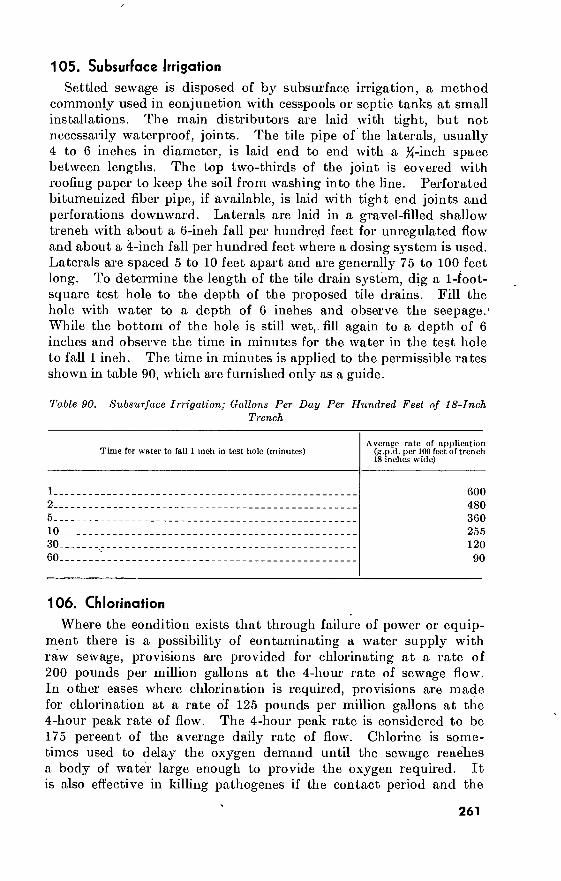
105. Subsurface Irrigation
Settled sewage is disposed of by subsurface irrigation, a method commonly used in conjunction with cesspools or septic tanks at small installations. The main distributors are laid with tight, but not necessarily waterproof, joints. The tile pipe of the laterals, usually 4 to 6 inches in diameter, is laid end to end with a %-inch space between lengths. The top two-thirds of the joint is covered with roofing paper to keep the soil from washing into the line. Perforated bitumenized fiber pipe, if available, is laid with tight end joints and perforations downward. Laterals are laid in a gravel-filled shallow trench with about a 6-inch fall per hundred feet for unregulated flow and about a 4-inch fall per hundred feet where a dosing system is used. Laterals are spaced 5 to 10 feet apart and are generally 75 to 100 feet long. To determine the length of the tile drain system, dig a 1-foot- square test hole to the depth of the proposed tile drains. Fill the hole with water to a depth of 6 inches and observe the seepage.' While the bottom of the hole is still wet,, fill again to a depth of 6 inches and observe the time in minutes for the water in the test hole to fall 1 inch. The time in minutes is applied to the permissible rates shown in table 90, which are furnished only as a guide.
Table 90. Subsurface Irrigation; Gallons Per Day Per Hundred Feet of 18-Inch Trench
1..
2__
5_ .
10_
30_
60-
Time for water to fall 1 inch in test hole (minutes) Average rate of application
(g.p.d. per 100 feet of trench 18 inches wide)
600 480 360 255 120 90
106. Chlorination
Where the condition exists that through failure of power or equip- ment there is a possibility of contaminating a water supply with raw sewage, provisions are provided for chlorinating at a rate of 200 pounds per million gallons at the 4-hour rate of sewage flow. In other cases where chlorination is required, provisions are made for chlorination at a rate of 125 pounds per million gallons at the 4-hour peak rate of flow. The 4-hour peak rate is considered to be 175 percent of the average daily rate of flow. Chlorine is some- times used to delay the oxygen demand until the sewage reaches a body of water large enough to provide the oxygen required. It is also effective in killing pathogenes if the contact period and the
261

■chlorine concentration are sufficient, and all particles are finely enough divided to permit chlorine contact. The chlorine dosages given in table 91 are high and are designed to safeguard health and prevent serious nuisance in emergencies; they are substitutes for other processes of sewage treatment. Chlorine is applied by mechani- cal chlorinators or an improvised drum chlorinator. The data given in table 91 are based upon obtaining a chlorine residual of 0.5 parts per million after a contact time of 15 minutes.
Table 91. Sewage Chlorination Dosages
Type of sewage or effluent Approximate dosage (pounds
per day liquid chlorine per 1.000 persons)
Raw sewage Settled sewage ' Trickling-filter effluent Surface- or subsurface-irrigation effluent .
40 30 10
5
107. Maintenance oí Sewers
a. Repair. Sewer repair consists principally of replacing broken manhole covers and ring assemblies and cracked or crushed lengths of pipe. Sections of bell-and-spigot clay pipe are installed by chip- ping off one-half the bell of the length to be inserted, chipping off upper portion of bell on the section of pipe below the gap, inserting the new section and rotating so the unchipped half of the bell is on the bottom, and completing the joint with mortar or mastic.
b. Methods. (1) Stoppages. The clearing of stoppages is the most important
item of sewer maintenance. Tree roots, particularly poplars, willows, and elms, penetrate pipe joints and clog sewers. Large objects and deposits decrease or stop flow. Sluggish flow, accumulated scum, or sewage backed up in a manhole indicates that repair or cleaning is required.
(2) Methods. (a) Sewers are cleaned by push rods, wooden balls, or flushing.
Push rods 4 feet long are jointed and pushed through the sewer from manhole to manhole. Special tools are attached to the first rod to clear deposits or cut tree roots. The use of rods becomes difficult when the distance exceeds 300 feet.
(b) Wooden balls of one-half or three-fourths the diameter of the pipe can be used to clean deposits from sewers. They are placed in the sewer and recovered by placing a coarse screen in the manhole downstream. The sewage
262
backed up behind tbc ball escapes around it at high velocity, scouring out solids deposited in the pipe.
(c) Sewers are flushed out by damming the outlet in a manhole with a sandbag, and removing the bag with an attached rope after the manhole has partially filled. Backed-up sewage is then released to scour out deposits. Care is taken not to back up sewage into fixtures and inlets in buildings. Discarded fire hose also is used for flushing. Water pressure makes the hose stiff enough to be pushed through short lengths of pipe.
c. Safety. Sewer gas, methane, hydrogen sulfide, or gasoline and oil drainings can fill sewers with explosive mixtures. Carbon monox- ide is particularly dangerous because it is often present in sewers and is not perceptible to the human senses. It may cause a slight headache preceding unconsciousness. Although some of the lighter gases arc removed by opening manholes, the weight of carbon monox- ide is about the same as air and it is removed only by using a blower. Sewer repair men should work in pairs, one staying above ground to observe and aid the other if necessary. A rope is sometimes tied around the man below ground to lift him out if he becomes uncon- scious. Chemical detectors for carbon monoxide are made, but if they are not available, a bird in a cage lowered into a manhole is observed for the effects of gas. A considerable concentration of carbon monoxide makes a man unconscious almost immediately, and death is avoided only by artificial respiration, immediately and properly administered.
Section III. REFUSE COLLECTION AND DISPOSAL
108. General
a. Refuse consists of garbage, rubbish, ashes, debris, and other domestic and commercial solid waste material.
(1) Garbage is the animal vegetable waste and containers result- ing from the handling, preparation, cooking, and consump- tion of foods.
(2) Rubbish consists of discarded unsalvaged waste material such as metal, glass, crockery, floor sweepings, paper, wrappings, containers, cartons, and similar articles.
(3) Ashes include the residue from burning wood, coal, coke, and other combustible material used in heating and cooking.
(4) Debris consists of such items as grass cuttings, tree trim- mings, stumps, street sweepings, roofing and construction wastes, and similar waste material resulting from construc- tion, maintenance, and repair work.
b. Refuse collection and disposal are discussed in TM 5-634.
263
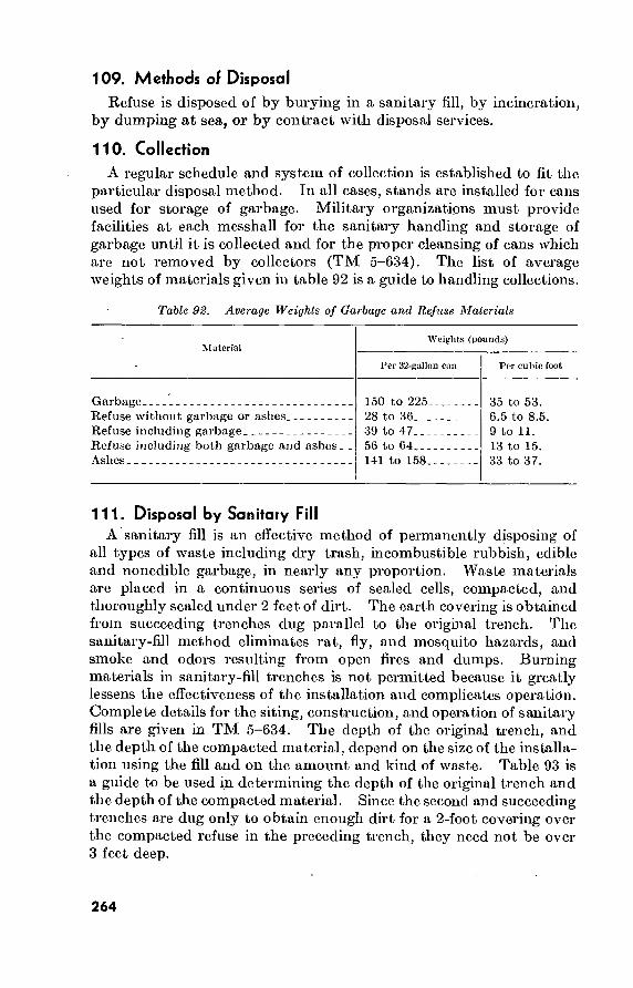
109. Methods of Disposal Refuse is disposed of by burying in a sanitary fill, by incineration,
by dumping at sea, or by contract with disposal services.
110. Collection A regular schedule and system of collection is established to fit the
particular disposal method. In all cases, stands are installed for cans used for storage of garbage. Military organizations must provide facilities at each messhall for the sanitary handling and storage of garbage until it is collected and for the proper cleansing of cans which are not removed by collectors (TM 5-634). The list of average weights of materials given in table 92 is a guide to handling collections.
Table 92. Average Weights of Garbage and Refuse Materials
Material Weights (pounds)
Per 32-gallon can Per cubic foot
Garbage Refuse without garbage or ashes Refuse including garbage Refuse including both garbage and ashes_ Ashes
150 to 225_ 28 to 36 39 to 47. 56 to 64 141 to 158-
35 to 53. 6.5 to 8.5. 9 to 11. 13 to 15. 33 to 37.
111. Disposal by Sanitary Fill A sanitary fill is an effective method of permanently disposing of
all types of waste including dry trash, incombustible rubbish, edible and nonedible garbage, in nearly any proportion. Waste materials are placed in a continuous series of sealed cells, compacted, and thoroughly sealed under 2 feet of dirt. The earth covering is obtained from succeeding trenches dug parallel to the original trench. The sanitary-fill method eliminates rat, fly, and mosquito hazards, and smoke and odors resulting from open fires and dumps. Burning materials in sanitary-fill trenches is not permitted because it greatly lessens the effectiveness of the installation and complicates operation. Complete details for the siting, construction, and operation of sanitary fills are given in TM 5-634. The depth of the original trench, and the depth of the compacted material, depend on the size of the installa- tion using the fill and on the amount and kind of waste. Table 93 is a guide to be used in determining the depth of the original trench and the depth of the compacted material. Since the second and succeeding trenches are dug only to obtain enough dirt for a 2-foot covering over the compacted refuse in the preceding trench, they need not be over 3 feet deep.
264

Table 98. Depths, Sanitary Fills
Size of installation Depth of
compacted refuse (feet)
Depth of original
trench (feet)
1.000 to 2,000 men__ 2.000 to 4,000 men_. 4.000 to 6,000 men__ 6.000 to 8,000 men.. 8.000 to 10,000 men.
3 3>i 4 4
112. Disposal by Incineration a. General. Incineration is the disposal of refuse by burning
in specially constructed furnaces. Incineration destroys all organic matter, both gaseous and solid, and eliminates all substances likely to undergo bacterial decomposition. Garbage, rubbish, dead animals, and dried sludge from sewage disposal are burned in incinerators. Mixed refuse usually contains enough combustible material to provide the fuel for burning. Additional fuel is used when burning garbage alone.
b. Garbage is shoveled through a charging hole and onto an inclined drying hearth. Flames and hot gases produced by burning material on the grate dry the wet garbage on the drying hearth. As the garbage dries, it falls or is raked down to the burning grates where it burns and forms a solid mass or clinker. This clinker is broken up from time to time and removed to keep it from clogging the burning grate. The ash falls into a pit under the burning grate and it is removed when necessary. The ash is disposed of in open dumps.
c. Construction. One large centrally located incinerator for a base camp or hospital is generally more efficient than a separate small incinerator for each unit. However, when the construction of one central incinerator is not possible, several smaller incinerators are built. Occasionally, because of the limited capacity of incinerators, it is necessary to construct a battery of incinerators at the central location. Construction details for incinerators are given in TM 5-280 and TM 5-634.
d. Operation. For adequate drying and combustion, the incinerator is heated before attempting to dispose of garbage. A fire is started in the furnace with clean, dry rubbish saved from a previous operation or with wood or coal. After the furnace is hot, the wet refuse is placed on the drying grate at reasonable intervals. Care is taken not to overload the incinerator with wet garbage. As the garbage dries, it is moved toward the burning grate making room on the drying grate ■ for the next charge of wet garbage. Garbage is stored as close to the. charging holes as possible for ease in charging. To make the greatest use of the heat, the plant should be operated with as few shutdowns as
265

possible. The charging holes are kept open only when absolutely necessary, because the furnace cools rapidly. Tin cans carried into the furnace with the garbage are removed frequently to prevent decreasing the burning capacity of the grates. Glass, china, box straps, and other metal scrap are removed from the refuse before burning because they impair the efficiency of the incinerator.
e. Collection. Garbage is brought to the incinerators in cans or in truck bodies. The garbage is stockpiled at the charging hole from the cans or trucks. The collection schedule is arranged so lack of garbage does not stop the incinerator. The best collection time is during the forenoon.
113. Disposal by Dumping at Sea Disposal by dumping at sea is not recommended where other
methods can be used. It is most practicable for island installations, where the use of sanitary fills is impossible or the construction of incinerators is not feasible. Where islands are close to an inhabited friendly shore, or the body of water is relatively small, disposal by dumping at sea is inadvisable. When dumping in large bodies of water, the direction of prevailing winds and currents is considered so as to prevent return of the garbage to shore and to avoid defiling shores elsewhere. The garbage is loaded directly from cans or trucks onto the barge, scow, or other means of transportation, hauled at least 5 miles offshore, and dumped.
114. Disposal of Refuse Alone a. General. Garbage type incinerators and sanitary fills are not
practicable for disposing of large amounts of crating, scrap lumber, street sweepings, and incombustible trash. Crating and lumber pro- duce too much heat for ordinary incinerators. The two common methods of disposing of refuse alone are burning pits and regulated dumps.
b. Burning Pits. Masonry or earth pits of varying size and design to meet local requirements are used to burn combustible refuse. However, they are fire hazards and their construction and method of operation must be approved by all fire-protection agencies. The pits are cleaned weekly and all ashes, metal, and other incombustibles arc disposed of on regulated dumps. The design of earthen pits depends on the terrain and the quantity of refuse to be burned. A suggested design is a revetment with two horseshoe-shaped cells; each cell is used alternately for dumping and burning. If the pit is large, the ashes are left in the bottom, but periodically they are leveled with a bulldozer or scraper. If the area of the pit is limited, the ashes and incombustibles are removed and placed on a regulated dump.
266

c. Regulated Dumps. Regulated dumps are used to dispose of incombustible trash. They are built like embankments or highway fills of limited height and area and situated so that they are compacted daily by truck traffic. They are leveled periodically by a bulldozer and kept orderly and free of objectionable contents. If properly operated, regulated dumps are used to reclaim worthless land. Refuse is not dumped over an embankment or the brow of a hill making a high-face dump, because dumps of this kind are difficult to operate under regulated-dump standards.
Section IV. ELECTRIC-POWER DISTRIBUTION
115. General Electric transmission and distribution is discussed in detail in TM
5-765. Power generation in the field is developed in TM 5-766.
116. Foreign Voltages and Frequencies Electric current for lights, motors, and other appliances is usually
used at voltages of 115 or 208 volts and distributed at multiples thereof, but there are important exceptions; e.g., the prevailing voltage in Japan is 100. As to the frequencies in alternating current, the lower frequencies permit higher power factors in certain types of motors but cause flicker in incandescent light. The present standard frequency in the United States is 60 cycles, except that 25-cycle current is used for power in some industrial installations. In Europe, a frequency of 50 cycles for illumination and 25- and 42-cycle current for power are standard. Direct-current voltages and alternating- current voltages and frequencies generally used in various countries are given in table 94 (low-voltage supplies only).
117. Single-Phase Systems Buildings containing single-phase equipment, such as lights, X-ray
machines, or single-phase motors are served by two- or three-wire systems. Small loads as required for barracks lighting are served by two-wire systems; large loads require three-wire service.
a. Two-Wire Systems. In single-phase systems using two wires, the current in one wire always equals the current in the other, but flows in the opposite direction. Currents in the two wires reverse simultaneously.
b. Three-Wire Systems. Single-phase systems of three wires supply two voltages simultaneously. One wire is the neutral and is grounded; the other two are the hot wires. Figure 50 shows a typical single- phase three-wire system.
267

268
Coutiuent aud country
North America: United States
Alaska
British Honduras British West Indies:
Antigua Bahamas Barbados Bermuda Dominica Grenada Jamaica Saint Kitts Trinidad
Canada
Costa Rica Cuba Dominican Republic French West Indies:
Guadeloupe Martinique
Tabic 94■ Worldwide Direcl-Carrenl and AUcrnalintj-Carrcnl Vollayes
Direct-current voltage
Prevailing
120/240.
(b)
110/220 ».
220
(b)~ (b)- (b)- 220 ■ (b)-
(b)-
(b)-
(b)~
(”)-
(b)-
(b)-
(b)-
(b)-
(b)-
Other
115/230, 500, 000..
(b)
(b)
(b)-
(b)-
(b)-
(b)-
(")-
(b)-
(b)-
(b)-
(b)-
(b)-
(b)-
(b)-
(b)-
(b)-
(b)-
Alterimting-eurront voltugc
Prevailing
120/208, 120/240 ».
120/240 »
(b)
(b) 115 » 110 »
110/220 ».
(») 230 « 110/220 ».
110 »
110/230 ». 110/220 ».
110/220 »
110/220/440 ». 110/220/440 ».
110 »
110/220 ».
O tiler
110/220, 115/230, 220/440, 230/460, 240/480.
110/220, 115/230, 120/208.
(b)
« no, 120, 220
(b) (b) (b) ('•) (b) CO « 115, 120, 230, 550,
575. (b) 115 120/240
(b)-
(b)-
Frcciueiicy
Prevailing Other
60
60
(b)
(b)
(b)
60 60 60
)
50 40 60 60 60
60 60 60
50 50
25
(b)
(b)
(b)
(b)
(b)
(b)
(b)
(b)
(b) (b) (b)
25
(b)
(b) (b)
(b)
(b)
' tffi1
if
)

269
Guatemala Haiti
Honduras Mexico Netherlands West Indies:
Aruba Curacao
Newfoundland Nicaragua Panama, Republic Panama Canal Zone Puerto Rico El Salvador Virgin Islands South America:
Argentina Bolivia Brazil Chile Colombia
Ecuador Guiana, British
1 Guiana, Dutch (Surinam).
- Guiana, French Paraguay Peru
Uruguay Venezuela
220 440/500
120/220
(b)-—-
(b)
(b) (b) 110/125
(b)
(b)~ — (b) —- 110 (b)
220 110/220 220 220 (») —-
220.
(b)-
(b)-
(b)- 220 220
(b)-
(b)-
(b) (b)
(b) (b)
(b) — (b) (b) (b) (b) (b)
(b)
(b)
(b)
235, 380, 550
(b) (b)
240
(b)
(b)
(b)
(»)
(») (b) no
(b) (b)
See footnotes at end of table.
110/220 *.
115 *
110/220 •_
110/125“.
115/120 ».
125 » 110/220 ».
110/220 •.
110/220 «_
110 *
115/230 ». 110/220 a.
120/240 a _
230/400 110/190, 220/230,
380, 440/500.
(b) 115, 120, 210, 220.
110/220
220 (b)
(b)
(b) (b)
120/240, 220/440. (b)
(b)
60
60
60
60
60
50 60
60
60
25 60 60
60
220 “
110/220 ",
120/220 ».
220 •
110/220 •_
110/220 •_
115/230 *.
125 »
110*
220 *
220 *
220 *
110/220 *.
225/390, 380, 440. . 127, 230, 240
110, 115, 127
110, 380..
115, 150, 230, 260 380.
380.
110/220
220, 440
(b)_. (b)
110, 115, 230, 240,
380/500.
(b)
120, 240
50
50 50
50
60
60
50
50
50
50
60
50
50
50 50
(") 50
(b) (")
(b) (b)
50
(b) (b) (b) (b)
25, 60
60 60
60
50
50
60
60
(b) (b)
50
-(b) 60

27
0
Table 9^. Worldwide Direcl-Currenl and Allernaliny-Currenl Voltages—Continued
Continent and country
Europe: Albania. Austria..
Azores... Belgium.
Bulgaria Czechoslovakia.
Denmark. Finland...
France
Germany.
Gibraltar. Greece Hungary..
Iceland. Ireland.
Direct-current voltage
Prevailing
125. 220.
220.
110.
220 110/220.
220.
120.
110/220.
220
440. 220.
220.
C*)-
220.
Other
150 110, 440, 550, and
others.
(b) 220/440..,
440 120, 150, 440, and
others. 110, 440, 550 220
120, 190, 380, 440, 550.
110, 440, and others.
(b) 110, 440. no, 120.
(b)-
(b)-
Altcrnating-current voltage
Prevailing
220 220/380 ■
(b)~
220 ■
220 220»
220»
220/380».
127/220».
220/380..
240.. 127.. 220».
220..
220».
Other
125, 150, 380 125/220, 110/220,
125, 120, 110, and others.
(b) 110, 127, 135, 190,
380. 120, 150, 380 110, 115, 127, 380,
and others. 110, 120, 208, 380.. 110, 120, 208, 115,
127, 190. 110 to 120, 150,
190, 200, 208, 380. 110 to 127 and
others.
110, 150, 220, 380. _ 110, 115, 120, and
others.
O') 200, 380
Frequency
Prevailing Other
50 50
50 50
50 50
50 50
50
50
50 50 50
50 50
(b)
(b)
(b)
(b)
(b) 42
(")
(b)
25
25
(b) 25, 42
42
(b)
(b)

533500
Italy
a o
»
IO N
Luxembourg Malta Monaco Netherlands Norway
Poland Portugal Rumania Spain
Sweden
Switzerland
Trieste Turkey Union of Soviet So-
cialist Republics. United Kingdom Vatican City Yugoslavia
Asia: Aden Afghanistan Arabia Bhutan
220
110, 220.-4
O’) (b) 220 220
220 220 220, 220/440»._. 110
220
220
« 220 220
230 (*>) 110
(b)
(b)- 220»
110, 150, 380, 440, 550, and others.
(b) (") (") 127 110, 440
110, 500, 600 440 110, 120, 150 120, 130, 150, 240,
220, 300. 110, 120, 220/440,
and others. 160, 440, 600, and
others. (b) no 115, 250, 440
220, 440
(b) 120
(b)-
(b)- 440
See footnote at eud oí table.
125/220»
220, 380» 105 110, 115 220»
220»
220» 110» 110, 220, 220/380 liOto 130»
220/380, 127/220»....
220/380, 220, 380»...
220, 380, 500» 220 110/220
230» 125 220»
230/400 220/380 110/220/440. 120/220
120, 127, 150, 260 and others.
210 (») 127, 380 230, 130, 110, 120,
150, 380. 110 to 127 190, 220, 380 190, 208, 380, 550. 150, 220, 440, and
others. 110, 110/190 and
others. 110/190, 125, 145/
250, and others.
CO 110, 190/380 380
220, 240, 250 220 150 to 127, 150,
190, 380.
(b) 230 120/240, 250/433.. 380/440
50
50 100 42 50 50
50 50 50 50
50
50
42 50 50
50 45 50
50 50 60 60
(b)
CO O’) O’) O’) 25, 45
O’) O’)
42
25
(b)
O’) (b) '
O’)
40, 25
(b) 42
(b) 60 50
O’)

272
ri*?l'?i*i"n ‘r's"'r ' ' ' ‘ * •’^-~r1,•" '’ ^•’ '’• '* - ' ' ; '* , ^•■ ; r: ¡try
Table 94. Worldwide Direct-Current and Alternating-Current Voltages—Continued
Continent and country Direct-current voltage
Prevailing Other
Alternating-current voltage
Prevailing Other
Frequency
Prevailing Other
Asia—Continued British Malay:
Malayan Feder- ation.
North Borneo._ Singapore
Burma Ceylon
China.
Cyprus Taiwan French Indochina
Hong Kong. India..
Indonesia: Borneo Celebes Moluccas and
Minor Soenda Isles.
(b)-
« 230 220“
220/230.
220/440 (in Hankow).
220“
eo- lio.
(b) 220/440.
110.
(b)-
(b)~
(b)-
(b)-
220/440, 250/550. (b)
no.
(b) (b) 240, 120, 220.
(b) 220, 230, 225/450,
250/500, 230/460.
(b)-
(b)-
(b)-
230/400.
230/400. 230/400. 230/400. 230/400.
220/380.
110 100/200. 120, 208.
200/346. 230/400.
127. 127. 127.
230/460 220, 230, 420 230/416, 220/230,
240/416. 110/220, 110/190,
120/300, 200/350, 220, 220/440.
(b) (b) 127/220, 220, 240,
110, 115.
(h) 200, 230, 220/380,
250/440.
110, 125. 220 (b)
50
60 50 50 50
50
50 60 50
50 50
50 50 50
40, 60
50
60
60, 25
(b)
(b)
(b)
(b) 25
(b) (b)
(b)

273 Java and Madura., Sumatra
Iran Iraq Israel Japan Jordan Korea Lebanon Manchuria Nepal Pakistan Philippines Syria Thailand (Siam) Turkey
Africa: Angola Algeria
Belgian Congo British West Africa:
Gambia Ghana (Gold Coast)__ Nigeria Sierra Leone
British East Africa: Canary Islands Kenya Mauritius Tanganyika Uganda Zanzibar
See footnotes at end of table.
(b) 220
220
220
(b) 100
(b)~—
(b)—
(b)—
(b)—
(b)—
220
(b) 110/220 220
220
(b) (b)
(b)-~-
(b) 220 »...
(b) (b)
None.. (b) (b) 220
(b) 220
(b) (b) no 440 00 O') (b) 00 00 225 O') oo O') O')...... 110, 120,
110
00 (b)
(b)
(b) 00 (b)
(b)
(b)
(b)
(b)
00 00
127/220 127/220, 127 220 220 220/380 100/200 220/380 100/200 110/190 110/220 120/220 230/400 220 110/220 » 110/220 220
(b) 127/220, 220/380 d.
220/380
230 230 230/400 d 230/400
110, 115 415/240 230... 230/400 240/415
(b)-
110/190, 220/380. 110/190, 220/380. 380 380 230/400
(b)-
220/380 (b) 380/440 220, 220/380. 110/220 200, 115, 190. 220, 230, 380- HO, 190/380.
220/380 115/200, 230/400,
500, 110.d
(>■)
(b)-
(b)-
(b)-
(b)-
190, 220. (») 400 (b) (b) O')
50 ■ 50
50 50 50
c 50, 60 50 60 50 50 60 50 60 50 50 50
50 50
50
50 50 50 50
50 50 50 50 50 50
(b)
(b)
(b)
(b) (b)
(b)
(b) (b)
(b) 25, 60
(b)
(b) (b)
(b)
(b)
(b)
(b)
(b)
(b)
(b)
(b) (b)
(b)
(b)
(b)
(b)
(b)
(b)

27
4
Table 94- Worldwide Direct-Current and Alternating-Current Voltages—Continued
Continent and country Direct-current voltage Alternating-current voltage Frequency
Prevailing Other Prevailing Other Prevailing Other
Egypt.
Ethiopia (including Eritrea).
Federation of Rhodesia
220 »
b
110, 440
(b)
220.
125/220, 127/220
100/220, 110/220, 380.
220/380
50
50
40
(b)
and Nyasaland: Northern Rhodesia Nyasaland Southern Rhodesia
French Cameroons French Equatorial Africa- French West Africa Liberia Libya Madagascar Morocco (southern zone)..
(b)
(b)
(b)
(b)
(b)
(b)
(b)
(b)
(b) (b)
(b)
(b)
(b)
(b)
(b)
(b)
(b)
(b)
(b)
(b)
220/380 230/400 220/380, 230/400 115/200 127/220 127/220 115 125 127/220 115/200
(b) (b) (b) (b) 220/380 220/380 220 220 (b) 230/400, 110/190,
500.
50 50 50 50 50 50 60 50 50 50
(b) (b)
(b)
(b)
(b)
(b)
(b)
(b)
(b) (b)
Morocco (northern zone).. Morocco (Tangier zone) _. Mozambique
(»)- (b)- 220
Seychelles Islands Sudan Trust Territory of Somali-
land. Tunisia
220 500. 120.
(b)-
(b) (b) 240, 250, 480, 550
127/220 110/190 220/380
(b)
(b)
(b)
(b) 240/415 230
(b) (») 110/190, 120, 220/
440, 230, 240.
(b) 230 127/220, 220/230
50 50 50
(b)
(b)
(b)
(b) (b) 50 (») 50 (b)
(b) 115/200 110/190, 220/380, 230/400.
50 (b)

27
5
220 Union of South Africa
Australia and Oceania: Australia:
New South Wales.
Queensland South Australia— Tasmania Victoria West Australia. _
Oceania: Fiji Islands Guam Hawaii New Caledonia.. New Zealand Samoa Islands
of Upolu and Savaii under New Zealand administra- tion.
Other Samoa Islands.
Tahiti
240
220 200 230 230 220
240/480 (b) (b) (b) 230
CO
(b)
(b)
220/440, 230, 230/460, 240, 250, 250/500.
(b)
220/440, 240 220, 230 480 b (b) 110, 230
110, 250
00-
(b) 00 230/460, 500 ('•)
(b)
(b)
* Indicates prevailing voltage-current combination. b Indicates, as a rule, that no further research has been performed, since prevailing
voltage and frequency have been indicated. » Southern Japan, 50. Northern Japan, 00.
220/380. 100, 120, 200, 230, 240, 250, 280, 380, 400, 500.
50 (b)
240. 415 b. 50 (b)
240. 200.
240. 230. 250.
415 b 230, 240. 415 b (b) (h)
50 50 50 50 40
(b) 25 (b)
(b)
(b)
240/415 110/220 «
120/208/240/480 1
125 230/400 110/220
(») (») (b) 110/220.
220/240. (b)
50 60 60 50 50 50
(b)
(b) (bl
(b)
(b)
(b)
110.
110.
(b).
(b)-
50
60
(b)
(b)
d J'ruvuiling voilages in Algeria aro 220/380 where possible, 127,220 elsewhere. The 110, 1 iri/200, and 230/400 voilages arc being changed to the prevailing standards. The 500 voilage is used for tramways and for rural distribution.
Note. 125/250 indicates that voltages arc associated. This has been added where sources indicated such condition.

GENERATOR
240V MOTOR
120 V LAMPS
HOT WIRE
zá 120V
NEUTRAL
240 V
et 120V
HOT WIRE J
Figure 50. Single-phase, three-wire system.
(1) Voltages. The voltage between the two hot wires equals the sum of the voltages between the neutral and each hot wire. Usually, the voltage between the two hot wires is twice the voltage between the neutral and either hot wire.
(2) Currents. The current in the neutral wire equals the difference between the currents in the hot wires, as shown in figure 51. Current flows in the neutral wire in the same direction as the current in the hot wire carrying the smaller current. If total watts of load connected between the neutral and the two hot wires are equal, the loads are balanced. Under tins condition, desirable in electric distribution systems, the current in one hot wire equals the current in the other and no current flows in the neutral.
118. Two-Phase Systems
The two-phase system has two single-phase currents having a dif- ference in phase of 90°. It is sometimes called “quarter-phase system.” The currents are distributed on the three-wire, four-wire, or five-wire system. This system is not in common usage except in certain locali- ties. Further information may be obtained from the American Electricians’ Handbook.
119. Three-Phase Systems
A three-phase system is three single-phase systems interlocked so the current in each phase reverses at a different instant than the current in either of the other two phases. Three-phase systems using
276

GENERATOR
HOT WIRE 5 AMPS
ÔC //1 v
NEUTRAL 2 AMPS'
HOT WIRE
* I '/ r-
cf //1 \\
3 AMPS
Figure 51. Current in neutral wire.
three-phase wires and one neutral wire provide a flexible means of obtaining both lighting and power from the same circuit and arc commonly used. When power oidy is required the neutral may be omitted. Three-phase systems arc better suited than single-phase systems to heavy loads, especially large motors. Figure 52 shows a typical three-phase four-wire system.
a. Voltages. Two voltages are available simultaneously from a three-phase four-wire system, the phasc-to-ncutral voltage and the phase-to-phasc voltage.
(1) Phase-to-neutral voltage is the voltage between any phase wire and the neutral.
(2) Phase-to-yhase voltage is the voltage between any two phase wires. Phase-to-phasc voltage equals 1.73 multiplied by the phase-to-neutral voltage.
b. Currents. As in the single-phase system, the loads between the neutral and each phase wire are balanced to reduce current in the neutral to a minimum. A perfectly balanced three-phase system carries equal currents in the phase wires and no current in the neutral.
120. Comparison of Systems
Systems are identified by the number of phases and wires and the voltages between wires. For example, in the single-phase three-wire
277

THREE PHASE GENERATOR
THREE PHASE. MOTOR □
PHASE-TO-PHASE Çppp VOLTAGE / 208V
PHASE I WIRE
PHASE 2 WIRE
PHASE 3 WIRE
NEUTRAL
PHASE TO NEUTRAL VOLTAGE 120 V
Figure 62. Three-phase four-wire system.
system, the voltage is 120 volts from hot wire to neutral, and 240 volts between hot wires. This notation is abbreviated l<f> 3w 120/ 240v. The three-phase four-wire system shown in figure 52 is abbre- viated 3<£ 4w 127/220v. Standard electrical sj-mbols are given in detail in TM 5-680.
121. Electric-Power Requirements a. General. Predetermine the maximum demand in kilowatts and
the average consumption of energy in kilowatt hours when selecting a suitable power supply, specifying the proper equipment, and computing the cost of electricity.
b. Maximum Demand. The most accurate means of estimating the demand is to determine the connected load and apply suitable diversity factors. These factors are based on experience with projects similar in character and size to that under consideration. A break- down of large projects and a classification of the types of service required may be helpful in estimating the total maximum demand and in applying the data obtained from other projects containing facilities of similar nature but not necessarily of the same size and composition. In general, the maximum 30-minute demand for the entire electrical system at posts, camps, and airfields will be approxi- mately 30 percent of the total connected load, and at storage depots will be approximately 200 kilowatts per million square feet of ware-
278

house area. For industrial plants, the maximum demand should be determined from data furnished by the using service. On a per capita and bed basis, the following demands will be sufficiently accurate for preliminary estimating purposes: Army camps 0.3 kw. per capita Air Force tactical bases 0.3 kw. per capita Air Force strategic bases 0.3 kw. per capita Research and development bases 1.3 kw. per capita Technical schools 0.6 kw. per capita Repair schools 1.5 kw. per capita Hospitals 2.0 kw. per bed In applying the above figures to a specific project, special applications must be considered. Where other than normal loads are to be sup- plied, allowances must be made for the demands that will be imposed by these loads.
c. Consumption. The average monthly consumption should be computed by multiplying the maximum demand by a suitable load factor and by the number of hours the facility will be in operation during the month. The load factor will usually be between 30 and 45 percent at posts, camps, airfields, and storage depots. For instance, at an Army post having a total connected load of 8,000 kilowatts, the estimated maximum demand would be 8,000X0.30 = 2,400 kilowatts. Using a load factor of 45 percent, the estimated average monthly consumption would be 2,400X0.45X720 = 777,600 kilowatt-hours. Similarly, using the per capita basis, at an Army post having an authorized strength of 8,000 men, the estimated maximum demand would be 8,000X0.3 = 2,400 kilowatts. Again using a load factor of 45 percent, the estimated average monthly consumption would be 2,400X0.45X720=777,600 kilowatt-hours.
122. Transformers
a. General. A transformer receives electrical energy from one circuit and transfers it to another circuit by magnetic action. The circuit from which energy is received is called the primary; the receiving circuit is the secondary. Usually the primary and secondary circuits are at different voltages. An elementary transformer consists of a primary and a secondary coil surrounding an iron core. Alter- nating current in the primary coil produces an alternating magnetic field in the iron core. A voltage is induced in the secondary coil by the alternating field.
b. Substation Transformers. Substation transformers should be of the outdoor type and of applicable self-cooled rating selected from standard transformer KVA ratings.
(1) Standard KVA ratings in single-phase transformers are: 3, 5, 10, 15, 25, 37.5, 50, 75, 100, 167, 250, 333, 500, 833, 1,250, 1,667, 2,500, 3,333, 5,000, 8,333, 12,500, 16,667, 20,000, 25,000, and 33,333.
279

(2) Standard KVA ratings in three-phase transformers are: 9, 15, 30, 45, 75, 112%, 150, 225, 300, 500, 750, 1,000, 1,500, 2,000, 2,500, 3,750, 5,000, 7,500, 10,000, 15,000, 25,000, 37,500, and 50,000.
c. Transformers Available in Oversea Depots. The following trans- formers are currently stocked in oversea depots:
Transformer, Current. Indoor, 25 to 125 Cycles, 1 Phase, Std Current Rating Primary, 200 AMP, Secondary 5 AMP, 1% In. Lg, 3% In. Dia, 2 Wire Lead Type Terminals.
Transformer, Current, Indoor, 25 to 125 Cycles, 1 Phase, Std Current Rating Primary, 500 AMP, Secondary 5 AMP, % In. Lg, 3% In. Dia, 2 Wire Lead Type Terminals.
Transformer, Power, Distribution, 3 KVA Continuous, Self- Std Cooled, 55 Deg C Rise Above Ambient Temp, 230 V Norn ASF High, 50 Cycle, Single Phase, 125 V Nom Low, 50 Cycle, Single Phase, Tapped At 115 V And 120 V, 2 Wire Service.
Transformer, Power, Step-Down, Input Primary, 3,000 V, Std 60 Cycles, 1 Phase, Output Secondary, 600 V, 6.6 AMP, 4 Wire Lead Type Terminals.
1 23. Generators a. Table 95 lists the alternating-current and direct-current gener-
ators available under the current standardization plan, although other miscellaneous generators still exist in supply channels. These standard generators are capable of supplying the power requirements of all power demands in the field.
b. The small alternating-current generators of 0.15-, 0.5- and 1.5-kw output ratings deliver 120-volts single-phase at frequencies of 60- or 400-cycles. The 1.5-kw, 60-cycle unit is the most versatile and widely used because its output is adequate for the communications and lighting requirements of small units in the field.
c. The alternating-current generators rated at power outputs of 3-, 5-, and 10-kw are all driven with gasoline engines, deliver 60- or 400- cycle ac, and have a change-over panel which permits connection for 120-208 volts, 3-phase, 4-wire, 120-volt, 3-phase, 3-wire, 120-volt, single phase, 2-wire; or 120/240-volt, single phase, 3-wire operation, each at the full rated kilowatt output. Because of this flexibility and range of power outputs, the 60-cycle group is quite versatile for gen- eral power requirements. The 10-kw, 60-cycle is the most versatile since its output is adequate for relatively large loads such as required by small maintenance shops. These generators are skid-mounted and usually covered with a protective housing.
d. Alternating-current generators of larger capacities up to 150-kw, are rated at 15-kw, 45-kw, 60-kw, 100-kw, and 150-kw and deliver 60- or 400-cycle, 3-phase, 4-wire power at 120/208 or 240/416 volts.
280

Output at 50 cycles is possible at 83 percent of the rated power output at 60 cycles. In addition to a diesel-driven model in each power rating, the 15-kw and 30-kw units arc available with gasoline-engine drive. The availability of both diesel and gasoline types can be an important advantage where one or the other fuel may be unobtainable or required. For example, a motor pool requiring only gasoline could well use a gasoline-driven generator for electric power, thereby simplifying fuel supply. The 60-kw diesel-driven generator is prob- ably the most widely used of the larger generators. Because the weight of the 60-kw units represents an easily-handled load for a 2/2-ton truck, whereas larger generator units require a less readily available 5-ton truck, several 60-kw units are frequently used in parallel to supply large loads.
e. The direct-current generators listed are used for such purposes as starting Army aircraft, battery charging, operation of communi- cation equipment, and as spare units to start heavy ground equipment. The majority of these units are gasoline driven and are easily trans- portable.
124. Power Systems
a. Load Estimation. (1) Connected load. Load estimation covers both the size and
location of the items making up the connected load. The structures to be served are identified and marked on an ac- curately scaled map of the area. The connected load for each structure is then established and tabulated. The con- nected load is the sum of the electric-current requirement of each motor, light, and other electrically operated devices, expressed in kilovolt-amperes (kv.-a.). One thousand watts in incandescent lamps, or 1 horsepower of motor or power load is taken as 1 kv.-a. in estimating the connected load. The connected light and power loads for various standard buildings are given in TM 5-302. Connected loads for other structures may be estimated by comparing floor areas.
(2) Demand load. The connected load is converted to demand load by applying a demand factor which is based on experi- ence. The term load or demand, used alone, means demand load, in kv.-a., required to serve a given connected load. It is less than the connected load because all of the lights or other electric devices are not in use simultaneously. The demand factor is the ratio of the maximum demand of a system, or part of the system, under consideration. De- mand factors for military structures are shown in table 96. Using these, the demand for each structure is computed and tabulated.
281

282
’.’»«nwtjpük.í• >••■•/. V'T^.’TíC ^ î»çm,w«f|B!M*N|Sllli?W
Frequency
Voltage..
Phase..
Wires
Fuel.
KW rating: 0.15 0.5 1.5 3 5 10 15 30 45 60 100___.
150
Table 95. Family of Engine-Generators
Alternating current
60-cycle
120 120/208
1 & 3
120/208,240/416
XI
xi
XI
xi xi
xi
xi
xi
400-cycles
120/208
1 & 3
120/208,240/416
Direct current
O D G D
- i
" -t
G—Gasoline driven. D—Diesel driven. 3-phase 4-\virc, 120 v 3-phase 3-\virc, 120 v single phase 2-wirc, 120/240 v single phase i—These generators to produce either 50- or 60-cycle current. 3-wirc. •“Panel connections permit, at rated KW output: 120/208 v 3-phase 4-wire, 120 v **—Still in early stages of development.
ML..-

Table 96. Demand Factors, Military Structures
Structure
Housing Aircraft maintenance, facilities Operation facilities Administrative facilities Shops Warehouses Medical facilities Theaters NAV aids Laundry, ice plants, and bakeries. All others
Demand factor
0. 9 . 7 . 8 . 8 . 7 . 5 . 8 . 5 . 7
1. 0 . 9
(3) Horsepower limits of electric motors by systems and voltages are shown in table 97.
(4) Standard horsepower ratings oj motors are: Ko, X2, %, }í, )í, X, X, %, 1, IK, 2, 3, 5, 7%, 10, 15, 20, 25, 30, 40, 50, 60, 75, 100, 125, 150, 200, 250, 300, 350, 400, 450, 500, 600, 700, 800, 900, 1,000, 1,250, 1,500, 1,750, 2,000, 2,250, 2,500, 3,000, 3,500, 4,000, 4,500, and 5,000.
6. Generator Location and Capacity. (1) Location. To reduce wire requirements, generators are
located preferably near points of large demand such as laundries, machine shops, bakeries, ice plants, and X-ray equipment. Generator locations are selected tentatively by map studj7 of the plotted demands. The size of the area served by each low-voltage generator or transformer depends upon the type and location of the demands. In general, small demands such as barracks lighting are served efficiently at distances up to 1,500 feet, moderate demands such as mess structures, up to 1,000 feet. Generators are located on firm ground and along existing roads. Concrete founda- tions are justified for semipermanent installations of 30- kilowatt or larger generators.
(2) Capacity. Generator capacity is based on the sum of the demands served but is less than the sum because the peak demands are not simultaneous. The sum of the individual demands, in kv.-a., is multiplied by a generator factor to determine the required generator capacity in kilowatts. The factor allows for both the power factor (pf) of the generator and for the noncoincidence of demands. Generator factors for theater-of-operations construction are given, in table 98. The diversity factor is discussed in TM 5-765.
283

Table 97. Horsepower Limits 1
System Voltages Minimum horsepower
Maximum horsepower
Alternating current, single phase.
Alternating current, two and three-phase.
Direct current.
110-115-120 220-230-240
440-550 110-115-120 220-230-240
440-550 2200 4000 6600
115 230
550-600
None None 5 None None None 40 75 400 None None Ji
IJi 10 10 15 200 500 None None None 30 200 None
•Reprinted from American Electricians' Handbook by Terrell Croft by permission of McGraw-Hill Company. Copyright 1042.
(3) Number of generators. Enough excess generator capacity is provided to supply the maximum demand with the largest generator out of service. In small systems, generators are preferably of the same size and type, for interchangeability and to reduce the requirements for spare parts. In larger systems, generators of different sizes are justified to permit more efficient operation. For example, if a 100-kilowatt lighting demand is served by one 30-kilowatt, one 70-kilo- watt, and one 100-kilowatt generator, any one generator can be out of service at any time; and the 30-kilowatt gen- erator will probably supply the entire demand in daytime hours.
(4) Interconnection. Generator locations in hospital areas and refrigeration warehouse areas are usually interconnected in insure uninterrupted service. Interconnections require addi- tional copper and are not justified except in hospital and refrigeration areas. If the supply of generators does not permit either interconnection or standby capacity as de- scribed in (3) above, the operating rooms and one or two lights per ward are wired on a special circuit to a small emergency generator.
c. Transformer Location and Capacity. Transformers are required wherever the utilization voltage differs from the transmission or dis- ’ tribution voltage. Their location is influenced by the same factors which affect generator locations (6(1) above). The proper trans- former capacity in kv.-a. is the sanie as the full demand in kv.-a.
284

Table 98. Generator Factors, Thealer-of-Operalions Construction
Typo of load Generator factor
Lighting Predominantly lighting with some motors Lighting with ranges and water heaters.. Lighting and motors about equal Predominantly motors with some lighting Motors
1. 00.
. 95
. 95
. 90
. 85
. 80
(without reduction as in the case of generators). In selecting and locating transformers for lighting loads in military housing areas, a frequently used combination is 10 kv.-a. transformer distributing through three No. 6 conductors carrying single-phase 120/240 volt current.
d. Line Location. Normally electric distribution systems are of the radial type; lines radiate from generators or substations toward loads, branching and rebranching until all areas are served. The alternative is the ring type system in which the main distribution line forms a closed loop. The ring type normally distributes with less voltage drop but requires more time and material to construct. Lines are normally overhead. Lines carrying voltages above 240 are supported on poles (TM 5-680C); those carrying 120-240 volts are supported on poles or on masts or insulators attached to buildings.
125. Selecting Wire Sizes a. Requirements. Electric conductors must be large enough to
carry the current without heating unduly and without excessive voltage drop. Except for very short lines, the latter requirement is usually the controlling one.
b. Current-Carrying Capacity. Table 99 gives data on current capacities, based on room temperatures of 30° C. (86° F.). Table 100 gives correction factors for temperatures over 40° C. (104° F.). See also tables 101, 102, 103, and 104.
c. Voltage drop. (1) Allowable drop. The voltage drop is the total loss of voltage
from the generator (or transformer or substation at which voltage is controlled) to the lights or motors. Part of the drop occurs in the distribution system (mains), part in the wires from the service entrance to the panel board (feeders), and part in the wires from the panel board to the outlet (branches). Electric wiring and distribution systems are planned for a total drop not in excess of 8 percent for lighting and 5 percent for power. Distribution is shown in table 105.
285-

(2) Drop in distribution lines. Voltage drop is difficult to com- pute but is obtained accurately enough for wiring layouts from the charts in figures 53 through 57. A separate chart is given for each voltage and type of circuit normally used in military systems. The upper scales of load and percent drop are used for heavier loads; the lower scales for light loads. Although drawn for 60-cycle current at various wire spacings, the charts may be used safely for 50-cycle current at the same spacings. In addition to the line voltage drop, a drop of one volt is added for each standard step-down trans- former which forms a part of any line between an initial known voltage and a final load.
(3) Voltage drop and wire sizes in branch circuits. Table 106 gives the wire sizes required for 115-volt circuits of various lengths of run, based on a drop of not more than two volts between the panel board and the outlets.
Table 99. Allowance Current Carrying Capacities of Conductors in Amperes for Not More Than Three Conductors in Raceway or Cable (Based on Room Temp- erature of 80° C. 86° F.) (See table 100)
Size AWG or MCM
14 12 10 8 6 4 3 2 1 0 00 000 0000 250 300
B (note 2)
Rubber tvpes R, RW, RU, RUW (14-2)
Type RTi- ll W (see note 1)
Thermoplastic types T, TW
15 20 30 40 55 70 80 95
110 125 145 165 195 215 240
Rubber type RH type
RH-RW (see note 1)
type RHW
15 20 30 45 65 85
100 115 130 150 175 200 230 255 285
Paper
Thermoplastic asbestos type TA
Var-Cam type V
asbestos Var-Cam type AVB
MI cable
25 30 40 50 70 90
105 120 140 155 185 210 235 270 300
Asbestos varnished-
cambric types AVA,
AVL
30 35 45 60 80
105 120 135 160 190 215 245 275 315 345
Impregnated asbestos types AI
(14-8) AIA
30 40 50 65 85
115 130 145 170 200 230 265 310 335 380
Asbestos types A
(14-8), A A
30 40 55 70 95
120 145 165 190 225 250 285 340
See notes at end of table.
286

Table 99—Continued
A B (note 2) O D E F O
Paper
Size A WO or MCM
Rubber types R, RW, RU, RUW (14-2)
Type RII- RW (see note 1)
Thermoplastic types T, TW
Rubber type RH type
RH-RW (see note 1)
type RHW
Thermoplastic asbestos type TA
Var-Cam type V
asbestos Var-Cam type AVB
Asbestos varnished- cambric
types AVA, AVL
I
Impregnated asbestos types AI
(14-8) AIA
Asbestos types A
(14-8), AA
MI cable
350 400 500 600 700 750 800 900 1000 1250 1500 1750 2000
260 280 320 355 385 400 410 435 455 495 520 545 560
310 335 380 420 460 475 490 520 545 590 625 650 665
325 360 405 455 490 500 515 555 585 645 700 735 775
390 420 470 525 560 580 600
420 450 500 545 600 620 640
680 730
785
840
Note t. If type RH-RW rubber-insulated wire is used in wet locations the allowable current carrying capacities will be that of column C, and if used in dry locations, the current carrying capacities will be that of column D. . '
Note 2. Insulation type and description. Type Description R RW RU RUW RII-RW RH RHW T TA TW MI A AA AI AIA A VA AVB AVL V
code-grade rubber compound moisture-resistant rubber compound latex-rubber compound latex-rubber, moisture-resistant compound heat- and molsture-resistantmbber compound heat-resistant rubber compound heat- and moisture-resistant compound thermoplastic covered for dry locations thermoplastic and asbestos-covered for switchboard wiring thermoplastic-covered for moist locations mineral-insulated, copper-sheathed for general use and special high-temperature locations non-impregnated, all-asbëstos, w/o asbestos outer braid non-impregnated, all-asbëstos, with asbestos outer braid impregnated, all-asbestos; w/o asbestos outer braid impregnated, all-asbestos; with asbestos outer .braid impregnated-asbestos and varnished-cambric with asbestos braid impregnated-asbestos and varnished-cambric, flame-resistant cotton braid impregnated-asbestos and varnished-cambric, outer asbestos braid, lead sheathed varnished-cambric
287 533506°—60- 19

Table 100. Correction Factors for Various Room Temperatures Over 40° C. (104° F-)
5 C.
40 45 50 55 60 70 75 80 90
100 120 140
' F.
104 113 122 131 140 158 167 176 194 212 248 284
B
0. 82 . 71 . 58 . 41
0. 88 . 82 . 75 . 67 . 58 . 35
0. 90 . 85 . 80 . 74 . 67 . 52 . 43 . 30
E
0. 94 . 90 . 87 . 83 . 79 . 71 . 66 . 61 . 50
0. 95 . 92 . 89 . 86 . 83 . 76 . 72 . 69 . 61 . 51
0. 91 . 87 . 86 . 84 . 80 . 77 . 69 . 59
Note. Columns B to G refer back: to table 99.
Table 101. Allowable Current-Carrying Capacities of Insulated Copper Conductors in Amperes
(Not more than three conductors in raceway or cable or direct burial (based on room temperature of 30° C. 86° F.))
Size AW G MCM
14 12 10 8 6 4 3 2 1 0
00 000
0000 250 300 350 400
Rubber type K
type RW
type RU type RUW
(14-2)
type R1L-RW see note
4a
thermo- plastic
type T type TW
15 20 30 40 55 70 80 95
110 125 145 165 195 215 240 260 280
Rubber type RH
RUII 04-2)
type RH-RW see note
4a
type RHW
15 20 30 45 65 85
100 115 130 150 175 200 230 255 285 310 335
Taper
thermo- plastic
asbestos type TA
Var-Cam type V
asbestos Var-Cam
AVB
MI cable
RHII (•)
25 30 40 50 70 90
105 120 140 155 185 210 235 270 300 325 360
Asbestos Var-Cam
tvpe AVA type AVL
30 35 45 60 80
105 120 135 160 190 215 245 275 315 345 390 420
Impreg- nated
asbestos type AI
(14-8) type AIA
30 40 50 65 85
115 130 145 170 200 230 265 310 335 380 420 450
Asbestos type A (14-8)
type AA
30 40 55 70 95
120 145 165 190 225 250 285 340
See footnotes at end of table.
288

Table 101. Allowable Current-Carrying Capacities of Insulated Copper Conductors in Amperes—Continued
Size A-WQ MCM
Rubber type R
type RW
type RU type RUW
(14-2)
type RH-RW see note
4a
thermo- plastic
type T type TW
Rubber type
RIl
Rim (14-2)
type RH-RW see note
4a
type RFTW
Paper
thermo- plastic
asbestos type TA
Var-Cam type V
asbestos Var-Cam
AVB
MI cable
RHH (0
Asbestos Var-Cam
type AVA type AVL
Impreg- nated
asbestos type AI
(14-8) type AIA
Asbestos type A (14-8)
type AA
500 600 700 750 800 900
1,000 1,250 1, 500 1,750 2,000
320 355 385 400 410 435 455 495 520 545 560
380 420 460 475 490. 520 545 590 625 650 665
405 455 490 500 515 555 585 645 700 735 775
470 525 560 580 600
500 545 600 620 640
680
785
840
730
Correction Factors, Room Temperatures over 30° C. 86° F.
' C. 40 45 50 55 60 70 75 80 90
100 120 140
° F. 104 113 122 131 140 158 167 176 194 212 248 284
0. 82 . 71 . 58 . 41
0. 88 . 82 . 75 . 67 . 58 . 35
0. 90 . 85 . 80 . 74 . 67
■.52 . 43 . 30
0. 94 . 90 . 87 . 83 . 79 . 71 . 66 . 61 . 50
0. 95 . 92 . 89 . 86 . 83 . 76 . 72 . 69 . 61 . 51
0. 91 . 87 . 86 . 84 . 80 . 77 . 69 . 59
See notes, following table 104.
■ The current-carrying capacities for type RHII conductors for sizes A WO 14,12, and 10 shall be the same as designated for type R11 conductors in this table.
289

Table 102. Allowable Current-Carrying Capacities of Insulated Copper Conductors in Amperes
Single Conductor in Free Air
(Based on room temperature of 30° C. 86° F.)
Size AWO MCM
14 12 10 8 6 4 3 2 1 0
00 000
0000 250 300 350 400 500 600 700 750 800 900
1, 000 1, 250 1, 500 1, 750 2, 000
Rubber type R
type RW
type RU type RÜW
(14-2)
type RH-RW see note
4a
thermo- plastic type T
type TW
20 25 40 55 80
105 120 140 165 195 225 260 300 340 375 420 455 515 575 630 655 680 730 780 890 980
1, 070 1, 155
Rubber type RU
RUIL (14-2)
tvpe RH-RW see note
4a
type RHW
20 25 40 65 95
125 145 170 195 230 265 310 360 405 445 505 545 620 690 755 785 815 870 935
1, 065 1, 175 1, 280 1, 385
Thermo- plastic
asbestos type TA
Var-Cam type V
asbestos Var-Cam
type AVB
Ml cable
Ritn (')
30 40 55 70
100 135 155 180 210 245 285 330 385 425 480 530 575 660 740 815 845 880 940
1, 000 1, 130 1, 260 1, 370 1, 470
Asbestos Var-Cam
type AVA type A VL
40 50 65 85
120 160 ISO 210 245 285 330 385 445 495 555 610 665 765 855 940 980
1, 020
1, 165
1, 450
1, 715
Impreg- nated
asbestos type AI
(14-8) type AIA
40 50 70 90
125 170 195 225 265 305 355 410 475 530 590 655 710 815 910
1, 005 1, 045 1, 085
1, 240
Asbestos type A
(14-8) type A A
45 55 75
100 135 180 210 240 280 325 370 430 510
Slow- burning
type SB
weather- proof type WP
30 40 55 70
100 130 150 175 205 235 275 320 370 410 460 510 555 630 710 780 810 845 905 965
1, 215
1, 405
See footnotes at end of table.
290

Table 102. Allowable Current-Carrying Capacities of insulated Copper Conductors in Amperes—Continued
Correction Factors, Room Temperatures over 30° C. 86° F.
Rubber type R
type RW'
Size AW G MCM
type RU type RUW
(H-2)
type R1T-RW see note
4a
thermo- plastic type T
type TW
Rubber type RH
RUH (14-2)
type RH-RW see note
4a
type RHW
Thermo- plastic
asbestos type TA
Var-Cam type V
asbestos Var-Cam
type AVB
MI cable
RHH (')
Asbestos Var-Cam
type AVA type AVL
Impreg- nated
asbestos type AI
(14-8) type AIA
Asbestos type A
(14-8) type AA
Slow- burning
type SB
weather- proof type WP
c. 40 45 50 55 60 70 75 80 90
100 120 140
3 F. 104 113 122 131 140 158 . 167 176 . 194 . 212 .
248 . 284 .
0. 82 . 71 . 58 . 41
0. 88 . 82 . 75 . 67 . 58 . 35
0. 90 . 85 . 80 . 74 . 67 . 52 . 43 . 30
0. 94 . 90 . 87 . 83 . 79 . 71 . 66 . 61 . 50
0. 95 . 92 . 89 . 86 . 83 . 76 . 72 . 69 . 61 .'51
. 91
. 87
. 86
. 84
. 80 .
. 77 .
. 69
. 59 .
See notes, following table 104.
> The current-carrying capacities for type RHH conductors for sizes AWG 14,12, and 10 shall be the samo as designated for type RII conductors in this table.
291

Table 103. Allowable Current-Carrying Capacities of Insulated Aluminum Conductors in Amperes
(Not More than Three Conductors in Raceway or Cable or Direct Burial (Based on room temperature of 30° C. 86° F.))
Size AWG MCM
Rubber type R,
RW, RU, RUW (12-2)
type RH-RW note 4a
thermo- plastic type T,
T\V
Rubber type RH
RUH (14-2)
type RH-RW note 4a
type RHW
Thermo- plastic
asbestos type TA
Var-Cam type V
asbestos Var-Cam type AVB
MI cable
RHH *
Asbestos Var-Cam
type AVA type AVL
Impreg- nated
asbestos type AI
(14-8) type AIA
Asbesto type A (14-8)
type A A
12 10
8 6 4 3
*2 *1 *0
*000 *0000
250 300 350 400 500 600 700 750 800 900
1, 000 1, 250 1, 500 1, 750 2, 000
15 25 30 40 55 65 75 85
100 115 130 155 170 190 210 225 260 285 310 320 330 355 375 405 435 455 470
15 25 40 50 65 75 90
100 120 135 155 180 205 230 250 270 310 340 375 385 395 425 445 485 520 545 560
25 30 40 55 70 80 95
110 125 145 165 185 215 240 260 290 330 370 395 405 415 455 480 530 580 615 650
25 35 45 60 80 95
105 125 150 170 195 215 250 275 310 335 380 425 455 470 485
560
650
705
30 40 50 65 90
100 115 135 160 180 210 245 270 305 335 360 405 440 485 500 520
600
30 45 55 75 95
115 130 150 180 200 225 270
See footnotes at end of table.
292

'fable 103. Allowable Current-Carrying Capacities of Insulated Aluminum Conductors in Amperes—Continued
Correction Factors, Room Temperatures over 30° C. 86° F.
O
Size A WO MCM
C. 0 F. 40 104 45 113 50 122 55 131 60 140 70 158 75 167 80 176 90 194
100 212 120 248 140 284
Rubber type R,
RW, RU, RUW (12-2)
type RH-RW note 4a
thermo- plastic type T,
TW
Rubber type RH
RUH (M-2)
type RH-RW note 4a
type RHW
Thermo- plastic
asbestos type TA
Var-Cam type V
asbestos Var-Cam type AVB
MI cable
RHH I
Asbestos Var-Cam
type AVA type AVL
Impreg- nated
asbestos type AI
(14-8) type AIA
0. 82 . 71 . 58 . 41
0. 88 . 82 . 75 . 67 . 58 . 35
0. 90 . 85 .80 . 74 . 67 . 52 . 43 . 30
0. 94 . 90 . 87 . 83 . 79 . 71 . 66 . 61 . 50
0. 95 . 92 . 89 . 86 . 83 . 76 . 72 . 69 . 61 . 51
Asbestos type A (14-8)
type AA
0. 91 . 87 . 86 . 84 . 80 . 77 . 69 . 59
See notes, following table 104. •For three wire, single phase service and sub-serviec circuits, the allowable currentcarrying capacity of
RH, RH-RW, RHH and RHW aluminum conductors shall be for sizes #2-100 amp., #1-110 amp., #1/0-125 amp., #2/0-150 amp., #3/0-170 amp., and #4/0-200 amp.
■ The current-carrying capacities for type RHH conductors for sizes AWO 12, 10, and 8 shall be the same as designated for type RH conductors in this table.
293

Table 104- Allowable Current-Carrying Capacities of Insulated Aluminum Conductors in Amperes
Single Conductor in Free Air (Based on room temperature of 30° C. 86° F.)
Size AW G MCM
Rubber type R,
RW, RU, RUW (12-2)
type RH-RW note 4a
thermo- plastic type T,
TW
Rubber type RM
RUH (14-2)
type RH-RW Note 4a
type RHW
Thermo- plastic
asbestos type TA
Var-Cam type V
asbestos Var-Cam
type A VB
Ml cable
RHH «
Asbestos Var-Cam
type AVA type AVL
Impreg- nated
asbestos type AI
(14-8) type AIA
Asbestos type A (14-8)
type AA
Slow- burning
type SB
Weather- proof type WP
12 10
8 6 4 3 2 1
0 00
000 0000
250 300 350 400 500 600 700 750 800 900
1000 1250 1500 1750 2000
20 30 45 60 80 95
110 130 150 175 200 230 265 290 330 355 405 455 500 515 535 580 625 710 795 875 960
20 30 55 75
100 115 135 155 180 210 240 280 315 350 395 425 485 545 595 620 645 700 750 855 950 050
1, 150
30 45 55 80
105 120 140 165 190 220 255 300 330 375 415 450 515 585 645 670 695 750 800 905
1, 020 1, 125 1, 220
40 50 65 95
125 140 165 190 220 255 300 345 385 435 475 520 595 675 745 775 805
930
1, 175
1, 425
40 55 70
100 135 150 175 205 240 275 320 370 415 460 510 555 635 720 795 825 855
990
45 60 80
105 140 165 185 220 255 290 335 400
30 45 55 80
100 115 135 160 185 215 250 290 320 360 400 435 490 560 615 640 670 725 770
985
1, 165
See footnotes at end of table.
294

Table 104. Allowable Current-Carrying Capacities of Insulated Aluminum Conductors in Amperes—Continued
Correction Factors, Room Temperatures over 30° C. 86° F.
Size AWO MCM
°C. °F. 40 104 45 113 50 122 55 131 60 140 70 158 75 167 80 176 90 194
100 212 120 248 140 284
Eubber type R,
RW. RU, RUW (12-2)
type RH-RW note 4 A
thermo- plastic type T,
TVV
0. 82 . 71 . 58 . 41
Rubber type RM
RUH (14-2)
type RH-RW Note 4a
type RH\ W
0. 88 . 82 . 75 . 67 . 58 . 35
Thermo- plastic
asbestos type TA
Var-Cam type V
asbestos Var-Cam
type AVB
MI cable
RHH »
0. 90 . 85 . 80 . 74 . 67 . 52 . 43 . 30
Asbestos Var-Cam
type AVA type AVL
0. 94 . 90 . 87 . 83 . 79 . 71 . 66 . 61 . 50
Impreg- nated
asbestos type AI
(14-8) type AIA
0. 95 . 92 . 89 . 86 . 83 . 76 . 72 . 69 . 61 . 51
Asbestos type A (14-8)
type A A
0. 91 . 87 . 86 . 84 . 80 . 77 . 69 . 59
Slow- burning-
type SB
Weather- proof type WP
See notes following table 104. i The current-carrying capacities for type R1 f H conductors for sizes AWO 12, 10, and 8 shall be the same
as designated for type RII conductors in this table.
295

Notes to Tables 101-104
■r. (Section references are to the National Electrical Code of 1956)
1. Aluminum conductors. For aluminum conductors, the allowable current- carrying capacities shall be in accordance with tables 103 and 104.
2. Bare conductors. If bare conductors are used with insulated conductors, their allowable current-carrying capacity shall be limited to that permitted for the insulated conductors of the same size.
3. Application of table. For open wiring on insulators and for concealed knob-and-tube work, the allowable current-carrying capacities of tables 102 and 104 shall be used. For all other recognized wiring methods, the allowable current-carrying capacities of tables 101 and 103 shall be used, unless otherwise provided in this code.
The temperature limitation on which the current-carrying capacities of type MI cable are based, is determined by the insulating materials used in the end seal. Termination fittings incorporating unimpregnated organic insulating materials are limited to 85° C. operation.
4. More than three conductors in a raceway. Tables 101 and 103 give the allowable current-carrying capacity for not more than three conductors in a raceway or cable. If the number of conductors in a raceway or cable is from 4 to 6 the allowable current-carrying capacity of each conductor shall be reduced to 80 percent of the values in tables 101 and 103. If the number of conductors in a raceway or cable is from 7 to 9, the allowable current-carrying capacity of each conductor shall be reduced to 70 percent of the values in tables 101 and 103. (Exceptions to the foregoing are specified in sections 3624, 3745, and 7265.)
4. a. If type RH-RW rubber insulated wire is used in wet locations the allowable current-carrying capacities shall be that of Column 2 in tables 101 to 104. If used in dry locations the allowable current-carrying capacities shall be that of column 3 in tables 101 to 104.
5. Neutral conductor. A neutral conductor which carries only the unbalanced current from other conductors, as in the case of normally balanced circuits of three or more conductors, shall not be counted in determining current-carrying capacities as provided for in the preceding paragraph. (In a 3-wire circuit consisting of two phase wires and the neutral of a 4-wire, 3-phase system, a common conductor carries approximately the same current as the other conductors and is not therefore considered as a neutral conductor.
6. Ultimate insulation temperature. In no case shall conductors be associated together in such a way with respect to the kind of circuit, the wiring method employed, or the number of conductors, that the limiting temperature of the conductors will be exceeded.
7. Use of conductors with higher operating temperatures. If the room temper- ature is within 10° C. of the maximum allowable operating temperature of the insulation, it is desirable to use an insulation with a higher maximum allowable operating temperature; although insulation can be used in a room temperature approaching its maximum allowable operating temperature limit if the current is reduced in accordance with the table of correction factors for different room temperatures.
8. Voltage drop. The allowable current-carrying capacities in tables 101 to 104 are based on temperature alone and do not take voltage drop into consideration.
9. Overcurrenl protection. If the standard ratings and settings of overcurrent devices do not correspond with the ratings and settings allowed for conductors, the next higher standard rating and setting may be used, but not exceeding 150 percent of the allowable carrying capacity of the conductor.
10. Deterioration of insulation. It should be noted that even the best grades of rubber insulation will deteriorate in time, so eventually will need to be replaced.
296

Table 105. Voltage Drop, Distribution Systems
Circuits
System voltage
110 220 230
Voltage drop in volts
eso
Lighting: Branches Mains and feeders, combined.
Total
4. 4 4. 4
8. 8
Power: Branches Mains and feeders, combined.
Total
2. 2 3. 3
5. 5
4. 6 4. 6
9. 2
2. 3 3. 5
5. 8
8. 8 8. 8
17. 6
2. 2 8. 8
11. 0
9. 2 9. 2
18. 4
2. 3 9. 2
11. 5
4. 4 17. 6
22. 0
5. 5 22. 0
27. 5
(4) A nomograph for finding voltage drop (approximately) is given in figure 58. Example: to find the size of wire to carry 10 amperes 100 feet with a 2-volt drop of potential; place a straightedge on 2 volts and 10 amperes, read .2 ohm at the intersection of the straightedge with the ohms scale; place the straightedge on .2 ohm and 100 feet, read No. 10 gage at the intersection of the straightedge with the A.W.G. scale.
126. Typical Electrical Layout for Hospital A typical electrical distribution layout for a 500-bed hospital,
Standard 3, is shown on figure 59. The load centers are each equipped with two 60-KW, 3</>, 4W 120-208V generators.
127. Pole Lines a. General. See TM 5-765 for construction details of overhead
distribution systems. In general, pole lines should be installed along streets or roads, wherever practicable, in order to avoid the need for separate poles for street lights. In connection with the selection of pole lengths, allowance should be made for the installation of tele- phone lines on all distribution poles. These lines are usually installed by the Signal Corps or the local telephone company, but the designer of the distribution system is responsible for the additional space and strength requirements. Specified pole lengths include the section below ground line.
b. Depth. Table 107 gives the depths to which poles of various lengths should be set in soil and in rock. Table 108 gives similar data for the case of rock overlaid with a thin layer of soil.
297

298 LOAD (KVA)
M ,3 EXAMPLE 2
10 3W 120V
A" WISE SPACING, 90* POWER FACTOR. 60 CYCLES
EXAMPLE 1
TO FIND WIRE SIZE. A 4*KVA
m
LOAD AT 90 FEET LIMITED TO
2 VOLTAGE DROP REQUIRES
NO 6 WIRE
EXAMPLE 2
EN r TO FIND VOLTAGE DROP. AN ll-KVA LOAD THROUGH 160 FEET OF
NO 4/0 WIRE CAUSES 1.9* VOLTAGE DROP
¡X
I P5
. TtP^ WA! «... _
WIRE SIZE
v 4/0
3:
Si 35:
‘5 II
sí LJ- fc: E
eg E s 12 ■à
m Igy o >
S00 LOAD (KVA)
200 300 400 CIRCUIT DISTANCE (FT)
Figure OS. Vollage-drop and luirc-sizc chart for single-phase two-wire IW-volt circuits.

299
io AP (KVA;
40 10
1 á 3W 1M/240V 12" EQUIVAlfNT WIKE.S^ íV 12" EQUIVAlfNT WlftE-SPACINO, 90% POWEI EACTOt, 60 CYCIE
:!!Í m
vnu sin 4/0
h
I
200 400 600 100 1000 1200 1400
CIICUIT DISTANCE (FT)
Il 10
Figure 54. Voltage-drop and wire-size chart for single-phase three-wire 1201240 volttircuits.
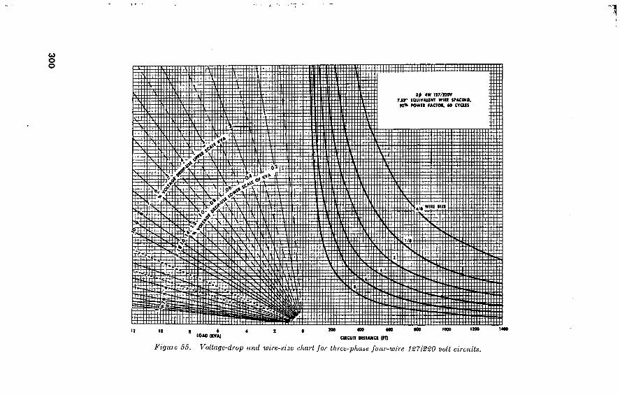
300
7
4W U7/2WV 7JÍ” EQUIVAUNT WIU SPACINO 90% POWft MCTOt, M CTCIfl
m
Si n
m I m V.'yOT—V
I S'.# *r-v s
WISE sin 4/0
v
il Try
piî S
0 i LOAD (KVA)
MO 400 «00 000 1000 IMO 1400
CIICUfT DISTANCE (PI)
Figure 55. Vollage-drup und wire-size chart for three-phase four-wire 1271220 volt circuits.

301 100 350
LOAD (KVA)
200 190 100
E:: m rs
S
I 10 JW 2400V 92" WIRE HACINO
90^ ROWER FACTOR 60 CTCUS ¡I ff B £-3
==K — Z
1 £±
58 t* c»
IWM & 3
mss 4/0 win sis
Í iâÉi g s I/o tt
W:
a =?
i il
10 0 3000 4000 6000 9000 10000 13000 14000
CIRCUI! DISTANCE (FT)
Figure 66. Vollngc-drop and wire-size chart for single-phase two-wire 2,400-volt circuits.

302
V-'T'' -k ■I
t
Id AO (KVA)
W
2400/41MV
U.I I OU IV Ail NT Will IFACINO »% MWKK FACTO* 60 CTCUt
I/O 11 III SIS
5Ê 1 0Î
m m
rîi ESE o*®?
10.000 12,000 14^00
CIKCUIT OtlTANCl (FT)
Figure 57. Voltage-dro'p and wire-size chart for three-phase four-wire 2,400l4:^d0-voit circuits.

53
35
00
Table 106. Watts per Circuit
Ci ©
to ©
Length ol run in feet (panel box to outlet)
100 150 200 400 500 000 700 800 900 1400 1(300 1800 2000 2200 2800 3000 3200
30 _ _ 40 _ _ 50. _ 60.. 70. _ 80..
90.. 100.
110.
120.
130. 140. 150- 160. 170. 180. 190. 200.
210.
220.
230. 240. 250.
14 14 14 14 14 14 14 14 14 14 14 14 14 14 14 14 14 14 14 14 14 14 14
14 14 14 14 14 14 14 14 14 14 14 14 14 14 14 14 14 14 14 14 14 14 14
14 14 14 14 14 14 14 14 14 14 14 14 14 14 14 14 14 14 14 14 12 12 12
14 14 14 14 14 14 14 14 14 14 14 14 12 12 12 12 12 12 12 12 12 10 10
14 14 14 14 14 14 14 14 14 12 12 12 12 12 12 10 10 10 10 10 10 10 10
14 14 14 14 14 14 12 12 12 12 12 12 10 10 10 10 10 10 10 10
8 8 8
14 14 14 14 14 12 12 12 12 10 10 10 10 10 10 10 8 8 8 8 8 8 8
14 14 14 14 12 12 12 12 10 10 10 10 10 8 8 8 8 8 8 8 8 8 8
14 14 14 12 12 12 10 10 10 10 10
8 8 8 8 8 8 8 8 8 6 6 6
14 14 12 12 12 10 10 10 10 10 8' 8 8 8 8 8 8 0 0 0 6 6 0
14 14 12 12 12 10 10 10 10 8 8 8 8 8 8 6 6 6 0 6 6 6 6
14 12 12 10 10 10 10 8 '8 8 8 8 6 0 6 6 6 6 6 6 6 4 4
14 12 12 10 10
8 8 8 8 8 6 6 6 6 6 6 4 4 4 4 4 4 4
12 12 10 10 8 8 8 8 8 6 6 6 0 0 0 4 4 4 4 4 4 4 4
12 10 10 10
8 8 8 6 6 6 6 0 0 4 4 4 4 4 4 4 4 4 4
12 10 10 8 8 8 6 6 6 6 6 6 4 4 4 4 4 4 4 2 2 2 2
12 10 10 8 8 8 6 6 6 0 4 4 4 4 4 4 4 4 2 2 2 2 2
10 10 8 8 8 6 6 6 6 4 4 4 4 4 4 4 4 2 2 2 2 2 2
10 10
8 8 6 0 6 6 6 4 4 4 4 4
- 4 2 2 2 2 2 2 2 2
10 8 8 8 6 6 6 0 4 4 4 4 4 4 2 2 2 2 2 2 2 2 2
10 8 8 6 0 6 6 4 4 4 4 4 4 2 2 2 2 2 2 2 2 1 1
10 8 8
' 6 0 0 4 4 4 4 4 4 2 2 2 2 2
.2 2 2 1 1 1
to o u

VOLTAGE
DROP
500 -
400“
300-
200-
100-
80-
SO-
40-
20 -
! 0-
8-
6-
5-
4-
3-
2- '
-X-
DI STANCE.
( FEET)
25000
20000-
I 5000-
10000-
8000-
6000-
5000-
4000-
3000-
2000-
1500
I 250-
1000-
800 -
600-
500-
400-
300-
200-
GAUGE
OHMS
-200
lOOz 80i 60-
40-
20-
8;
4-
2
BOO
.5 00
.300
✓ / y ' ,'.100- =
,'150- /
100-
/
Y
/.06" /
.04
.02
.008
.005
90 70
50
■30
I 0
6
eas
I 7-
I 6-
I 5
I 4-
13-
I 2-
I I -
I07 /
9-1 / /
/ 81
' 7r\ /
'6-t
CM*
2000
3000
4000
-5000
6000
7000 -8000 -9000 -10000
/
h20000
1.000/ '
: / / -J600
/ / -.400
r200
5
4-
3-
2-
I
08
T05
-.03
i.OI
-.006
-.004
1/0-
2/0-
3/0-
4/0-
AMPS
2
-3000 0
40000
-50000 -60000
-70000 -80000 90000 100000
-200000
300000
-400000
-50 0 0 0 0
4
5
6 .
-7 -8
-10
-15
20
-30
-40
-50
60
70 -80 -90
100
-150
-200
- 300
-400
500
CIRCULAR MILS = AMPERES X DISTANCE IN FEET X 21.6
VOLTAGE DROP
Figure 58. Wire sizes and voltage drops.
304
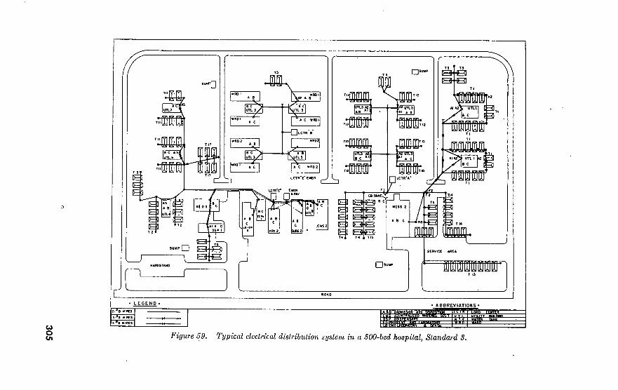
305
0
rjswp M ' 1
i
XSB12
I lM UTLSl * *■ * a I
B- -Q ^3 Q
E 13 UTU 13
—□ LCTR'B’
I WSDT
Mm
0 fV*jB *ltf
E3 I—lUCTR â
ucmc EUER i—i i—i «.ftar ce n
EJ QB El IB^3 E1 ^3 E3 E1 ^3 E3 El QQ
n;3 *10J S C 3
N u
-B 13 -E3 Î3 T«
ABC
B- Sll-B Q g=J. B
I B B □
' ABBREVIATIONS •
WiTM Y M-ftMB
Figure 59. Typical electrical distribution system in a 500-bed hospital, Standard S.

Table 107. Depth for Setting Pole in Soil or Rock
Height of pole (feet) Depth of setting (feet)
20.
25. 30. 35. 40. 45. 50. 55. 60.
In rock In soil
3/4
6/2 4'4 4M
Table 108. Division of Setting Depth in Feet Between Soil and Rock
30-foot pole
Soi! Rock
4 4 3 2 1M
40-foot pole
Soil
0 1 2 3 4 5
Rock
4 4 3 2
iM i
50-foot pole
Soil
0 1 2 3 4 5 6
Rock
4M 4M 4 3 2M 2 1
60-foot pole
Rock
5 5 4M 4 3 2 IK 1
c. Strength. The class of pole is determined on the basis of its ultimate breaking strength at the ground line as listed in table 109. Poles should have four times the strength required to support the actual vertical and transverse loading, except when the poles are guyed. The guy should support the entire load in the direction in which it acts, the pole simply acting as a strut. See l below for characteristics of guys.
Table 109. Breaking Strength of Classified Poles
Class Load, pound force
4,500. 3,700. 3,000. 2,400.
Class
5 6 7 8 to 10-
Load, pound force
1,900. 1,500. 1,200.
Not specified.
306
o
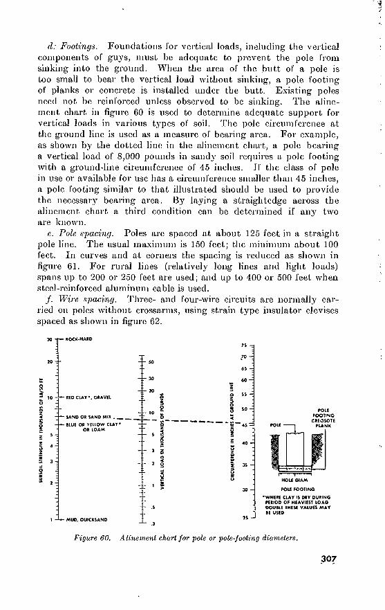
d: Footings. Foundations lor vertical loads, including the vertical components of guys, must be adequate to prevent the pole from sinking into the ground. When the area ol' the butt of a pole is too small to bear the vertical load without sinking, a pole footing of planks or concrete is installed under the butt. Existing poles need not be reinforced unless observed to be sinking. The aline- ment chart in figure 60 is used to determine adequate support for vertical loads in various types of soil. The pole circumference at the ground line is used as a measure of bearing area. For example, as shown by the dotted line in the alinement chart, a pole bearing a vertical load of 8,000 pounds in sandy soil requires a pole footing with a ground-line circumference of 45 inches. Jf the class of pole in use or available for use bas a circumference smaller than 45 inches, a pole footing similar to that illustrated should be used to provide the necessary bearing area. By laying a straightedge across the alinement chart a third condition can be determined if any two are known.
e. Pole spacing. Poles are spaced at about 125 feet in a straight pole line. The usual maximum is 150 feet; the minimum about 100 feet. In curves and at corners the spacing is reduced as shown in figure 61. For rural lines (relatively long lines and light loads) spans up to 200 or 250 feet are used; and up to 400 or 500 feet when steel-reinforced aluminum cable is used.
/. Wire spacing. Three- and four-wire circuits are normally car- ried on poles without crossarms, using strain t3rpe insulator clevises spaced as shown in figure 62.
s ^ 10 4—«0 CLAY*. GRAVEL
- — SANO OR SAND MIX . " O 5
_ >i « ie r\a ven r\uj ri A v • — — 8 ** “ Î2 “* « »
, ! - BLUE OR YELLOW CLAY*
OR LOAM
- MUD. QUICKSAND
7S
70 •
O 5 50-
Z
3 Z
o
2 O
POLE FOOTING
CREOSOTE POLE PLANK
HOLE DIAM
POLE FOOTING
•WHERE CUY IS DRY DURING PERIOD OF HEAVIEST LOAD DOUBLE THESE VALUES MAY BE USED
Figure 60. Alinement chart for pole or pole-footing diameters.
307

PULL
NOTE. If the "PULL" i* les» than 5', the spans adjacent to the angle pole may be standard 125' length. If the "PULL" exceeds 5', the spans adjacent to the angle pole shall be reduced to the distance given in the table.
Less Than 6°
6° . 110
15° - 22°
JDver -30°
PULL IN
FEET
Less Than 5'
10' - 13'
13'. 19'
Over 26'
SPAN FEET
NO OF 6000 # SIDE GUYS
1 ARM 6 WIRES
2 ARMS 12 WIRES
3 ARMS 18 WIRES
Figure 61. Pole spacing and side guys on curves.
g. Wire clearances aboveground. Minimum allowable clearances under various conditions are given in figure 63.
h. Wire. Diameters, weights, and resistances of wires normally used in overhead distribution systems are given in tables 110 through 114.
i. Sag. Sags in inches for various wire sizes, stringing tempera- tures, and span lengths, based on hard- and medium-drawn insulated copper wire, are shown in table 115.
j. Tension. The tension in an overhead wire, in parts of the weight of the wire span including any insulation and ice coating, and for various sag ratios is shown in table 116. The table also gives the vertical angle at which the wire leaves the pole, for plotting the ver- tical and horizontal components of the tension.
k. Loads and ultimate strengths of wire. See TM 5-765 for more complete data on loadings. The National Electrical Safety Code divides the United States into three zones classed as heavy, medium, and light loading areas, respectively, based on the ice and wind loads to be expected on overhead lines. (See figure 64.) The wind loads vary from 4 to 9 pounds per square foot, and the radial thickness of
308

NOTES;
1. This construction is for No. 8 wire or larger.
2. Max pole spacing for No. 8 wire, is 150*.
3. Service drop lengths should not exceed 100'. 4. For pole spans over 200', increase wire
spacing to 12".
■ i
r
ß
LS-
Hi:
Figure 62. Wire spacing on poles.
ice on conductors is one-half inch in the heavy zone (coupled with a temperature of 0° F.), one-fourth inch in the medium zone (at plus 15° F.) and none in the light zone. Tables 117 to 121 give the loading per foot of conductor for the three loading areas and strength data for conductors ordinarily used at Army installations. The allowable tension is usually taken as one-half the ultimate strength given in the tables.
Table 110. Bare Solid Copper Wire
Size (AWG) Diameter (inches) Weight (pounds per 1,000 feet)
Resistance (ohms per 1,000 feet at 20° C.)
4/0. 3/0. 2/0.
1/0-
1---
2...
3.-- •i___
5 6 7 8
0. 4600 . 4096 . 3648 . 3250 . 2893 . 2576 . 2294 . 2043 . 1819 . 1620 . 1443 . 1285
639. 8 507. 3 402. 4 319. 4 253. 0 200. 6 159. 1 126. 2 100. 0
79. 35 62. 96 49. 92
0. 04893 .06170 . 07780 .09811 . 1237 . 1560 . 1967 . 2480 . 3128 . 3944 . 4973 . 6271
309

15.000 TO 50.000 VOLTS
750 TO 15.000V
-X
0 TO J00v“T 750 TO""7 l«OOOU I I /
> O 0 jîio < o z 10 X >
c Z ► < 2 n » ► 2
o2c
PRIMARY LINS CONDUCTORS 750 TO 15.000
CONDUCTORS TO 750 VOLTS
M n IT Î0 18' 15' 15' u 22* 20' 18' 18' 18' 17* 15' 15' 12' 8' 77' 70'10’ 10’ 10 30'20'27'27'
8' VERTICAL 8' HORIZONTAL
MIN. I
..my
> o s ^ 5
o = 3 ss z y*
n CD ^ - > m ^ Z 3
o > >
io 2J «»
* is° z » »
** *" s
¡35
3o 5 w! z o
o < >. 3 » < ► >
SUPPLY CONDUCTORS •700 TO 50.000 VOLTS
NOTE FOR SPANS IN EXCESS OF 250'. ADD 0 T FOR EACH ADDITIONAL 10' IN MEDIUM FOR SPANS IN EXCESS OF 350*. ADD 0 1' FOR EACH ADDITIONAL 10' IN LIGHT
* SUPPLY WIRES 0 TO 150 VOLTS TO GROUND AT BUILDING ENTRANCES 10'
LOADING AREA.
LOADING AREA.
SUPPLY CONDUCTORS 750 TO 8700 VOLTS
SUPPLY CONDUCTORS 0
2' 2'
J_L
TO 750 VOLTS
MESSENGERS
V If
Mi
SPAN WIRES I
(«■-ni LLi
> Sz
“ f
o _
►*>S v. ? x S g < » z
n¡ S >
O m *
oil
r S d
lss sU o* 5
" ï 8
¡1
NOTES: 1. THE ABOVE CLEARANCES APPLY WHERE THE SPAN LENGTH OF THE UPPER CONDUCTOR DOES NOT EXCEED 250' FOR MEDIUM LOADING AREA AND 3S0' FOR LIGHT LOADING AREA. FOR LONGER SPANS, INCREASE THE CLEARANCE 0 15' FOR MEDIUM LOADING AND 0 10' FOR LIGHT LOADING AREA FOR EACH 10' IN SPAN LENGTH
2. CLEARANCE MARKED () INDICATES THAT IN GENERAL THE LINES OPERATING AT THE CORRESPONDING VOLTAGE SHOULD NOT CROSS OVER LINES AT THE HIGHER VOLTAGE
Figure 63. Minimum clearances of conductors.
Table 111. Weatherproof Solid Copper Wire
Size (AWG)
4/0_ 3/0- 2/0-
1/0-
1__-
2...
3--- 4 6 8
Diameter over insulation (inches)
Three-braid
0. 640 . 593 . 515 . 500 . 453 . 437 . 406 . 359 . 328 . 296
Two-braid
. 609
. 562
. 500
. 468
. 422
. 390
. 359
. 328
. 296
. 250
Weight (pounds per 1,000 feet)
Three-braid
767 629 502 407 316 260 199 . 64 112
75
Two-braid
723 587 467 377 294 239 185 151 100 66
Resistance (ohms per 1,000 feet at 20° C.)
0. 04893 . 06170 . 07780 . 09811 . 12370 . 15600 . 19670 . 24800 . 39440 . 62710
310

Table 112. Bare Stranded Copper Wire
Size (AWG) Diameter (inches)
Weight (pounds per 1,000 feet)
Resistance (ohms per 1,000 feet at 20° C.)
Wires in strand
4/0. 3/0. 2/0.
1/0.
1...
9
0. 5275 . 4644 . 4134 . 3684 . 3279 . 2919 . 2601 . 2316 . 1836
653. 14 412. 07 406. 98 322. 39 255. 45 202. 50 160. 60 127. 40
80. 10
0. 04997 . 06293 . 07935 . 10007 . 12617 . 15725 . 19827 . 25000 . 39767
19 7 7 7 7 7 7 7 7
Table 113. Weatherproof Stranded Copper Wire
Size (AWG)
4/0. 3/0. 2/0. 1/0.
Diameter over insulation (inches)
Three-braid
0. 812 . 734 . 687 . 640 . 593 . 531 . 468 . 437 . 406
Two-braid
0. 687 . 671 . 625 . 578 . 531 . 468 . 421 . 390 . 359
Wires in strand
19 7 7 7 7 7 7 7 7
Weight (pounds per 1,000 feet)
Three-braid Two-braid
800 653 522 424 328 270 206 . 70 115
745 604 482 388 303 246 190 155 103
Resistance (ohms per 1,000 feet at 20° C.)
0. 04997 .06293 .07935 .10007 . 12617 .15725 .19827 . 25000 . 39767
Table 114- Bare Solid Steel Wire
Size (BWG) Approximate
diameter (inches)
0. 238 . 203 . 165
Weight (pounds per
1,000 feet)
154 112
73. 5
Current load (amperes)
Resistance (ohms per mile at 20° C.)
7. 48 10. 15 15. 06
7. 59 10. 42
.15. 26
7. 92 10. 79 15. 71
9. 23 12. 47 18. 35
311

Table 115. Wire Sag in Inches
Wire size
AWG
String- ing
temp °F.
8
6...
4--.
1
1/0...
2/0
4/0—
30 60 90 30 60 90 30 60 90 30 60 90 30 60 90 30 60 90 30 60 90 30 60 90
Frigid and Temp Zones
Spans
100' 125' 150' 175' 200' 250' 300'
15 18 21.
8.
12 15. 8.
12 17 8.
12 17
8.
12 15. 8.
12 15. 8.
12 16 8.
12 16
23 37 31 14 18 22. 5 14 18 22. 5 14 18 22. 5 13. 5 18 22. 5 13. 5 18 22. 5 13. 5 18 22. 5 13. 5 18 22. 5
. 5
. 5
31 36 40 31 36 41 23. 5 30 35 22. 5 28 34 22. 5 28 34 22. 5 28 34 21 27 33
43 48 54 30 36 42 26 32 38 26 32 38 25 31 38 24. 30 36
53 60 67 42 49 56 42 49 56 38 46 53 31 38 46
89 96
103 66 72 82 66 72 82 57: 66 73 43 50 59
Tropical Zones
Spans
100' 125' 150' 175' 200' 250' 300'
14 18 22. 5
9 12 16 9
12 16 9
12 16 9
12 16 9
12 16. 5 9
12 16
8. 5 12 16
22. 5 27 32 14 18 22. 5 14 18 22 H 18 22 13. 5 18 23 14 18 23 13. 5 18 23 13. 5 18 23
i. 5 26 32 38 26 32 38 21 26 32 19 24 30 18 23 28 17. 5 22 28 16. 5 21 26
28 34 41 26 31 38 24. 5 30 36 23 28 35 20. 5 25 31
45 52 60 38 45 53 34 41 47 31 37 45 27 32 39
l. Guys and guy loads. The ordinary guying of poles at bends in lines is covered in e above. For heavier loads, dead ends, corners, and the like, find the resultant horizontal load by a parallelogram of forces, determine the guy slope practicable, and select guys from figure 65.
TO. Crossarms. See TM 5-765 for additional data. All crossarm loads are reduced to an equivalent load on the end pin, horizontally and vertically, and the horizontal unbalance is determined as shown in figure 66. The required crossarm size or any necessary doubling of crossarms is then selected from tables 122 and 123.
128. Wire Sizes Tables 124, 125, and 126 are based upon a voltage drop of about 3
percent.
312

Table 116. Wire-Sag Tension
Sag in parts of the span
Sag in decimal parts of span
Tension at polo in parts of the weight of the span of wire
Vertical angle of wire leaving pole
Length of wire in parts of span
1/300. 1/200.
1/150. 1/125. 1/100. 1/80.. 1/67.5. 1/50. . 1/40. . 1/35. . 1/30.. 1/25- . 1/20. .
1/15.. 1/10--
1/5--- 1/4... 1/3-.. 1/2.
0. 00333 . 005 .0067 . 008 . 01 . 0125 . 015 . 02 . 025 . 0286 . 0333 . 04 . 05 . 0667 . 1 . 2 . 25 . 333
Deg. 37. 5 25. 0 18. 8 15. 6 12. 5 10. 0 8. 45 6. 27 5. 03 4. 40 3. 78 3. 16 2. 55 1. 94 1. 35
. 800 . 707 . 625 . 559
0 1 1 1 2 2 3 4 5 6 7 9
11 14 21 38 45 53 63
Mm.
46 09 32 50 18 52 23 35 43 31 36 06 19 55 48 40 00 08 26
» 1. 00 1. 00 1. 00 1. 00 1. 00 1. 00 1. 00
1 1. 00
1 1. 00
1 1. 00
1 1. 00
1 1. 00 1. 01 1. 01 1. 03 1. 10 1. 15 1. 25 1. 48
1 Less than 1.005.
• L_
;
*
Figure 64- Loading map for overhead wires.
313

314
JF?" r-" : • - - — . - ■ 1 ’ - M ; î ^
Table 117. Solid Copper, Triple-Braid, Weatherproof Wire
Conductor size AWO
Ultimate strength (pounds)
Hard drawn
(minimum)
Medium hard drawn (minimum)
Annealed (maximum)
Loading (pounds per linear foot of conductor)
Light loading
Vertical (conductor without
ice)
Transverse (9- Ib. wind per square foot
on conductor without Ice)
Conductor loading 1
Medium loading
Vertical (conductor plus H-in. radial ice)
Transverse (4- 1b. wind per square foot
on ice-covered conductor)
Conductor loading 1
Heavy loading
Vertical (conductor plus ^-in. radial ice)
Transverse (4- 1b. wind per square foot
on ice-covered conductor)
Conductor loading 1
4/0 _ 3/0_ 2/0_
1/0-
1—
2...
3— 4 6 8 10-.
12..
7, 740 6, 390 5, 240 4, 290 3, 503 2, 850 2, 320 1,872 1, 216
785 503 402
6, 630 5, 380 4, 370 3, 540 2, 870 2, 330 1, 885 1, 505
960 612 390 249
6, 280 4, 980 3, 950 3, 130 2, 550 2, 030 1, 606 1, 274
801 504 330 207
0. 767 . 629 . 502 . 407 . 316 . 260 . 199 . 164 . 112 . 075 . 053 . 035
0. 578 . 533 . 473 . 428 . 390 . 356 . 315 . 293 . 251 . 218 . 188 . 158
1. 010 . 875 . 740 . 641 . 552 . 492 . 423 . 386 . 325 . 281 . 245 . 212
1. 084 . 927 . 776 . 662 . 555 . 485 . 407 . 363 . 294 . 243 . 208 . 178
0. 423 . 403 . 377 . 357 . 340 . 325 . 307 . 297 . 278 . 263 . 250 . 237
1. 384 1. 231 1. 083
. 972
. 872
. 803
. 730
. 689 . 625 . 578 . 545 . 516
1. 557 1. 381 1. 205 1. 072
. 950
. 866
. 771
. 717
. 631
. 566
. 519
. 476
0. 590 . 570 . 543 . 523 . 507 . 492 . 473 . 463 . 445 . 430 . 417 . 403
1. 975 1. 804 1. 632 1. 503 1. 387 1. 306 1. 215 1. 164 1. 082 1. 021 0. 976 0. 934
1 Conductor loading per foot as specified in Rule 251, NESC, 5th edition.

lUUUlUi
K.liUg 1
5. 429 4. 460 3. 385 2. 718 2. 278 2. 048 1. 855 1. 678 1. 554 1. 419 1. 339
Tabic 118. Stranded Cupper, Triple-Braid, Weatherproof Wire
Ultimate strength (pounds)
Medium Annealed hard drawn (maximum) (minimum)
32, 630 24, 840 16, 450 11, 590
8, 394 7, 105 5, 521 4, 409 3, 518 2, 810 2, 243
30, 510 22, 880 J 5, 260 10, 680
7, 628 6, 456 5, 119 4, 061 3, 2J9 2, 554 2, 107
Loading (pounds per linear loot of conducto
Light loading
Vertical (conductor without
ice)
3. 670 2. 822 I. 894 1. 345
. 984
. 800
. 653
. 522
. 424
. 328
. 270
T ransverse (0- lb. wind per square foot
on conductor without ice)
1. 275 1. 125
. 938
. 788
. 683
. 623
. 563
. 503.
. 465
. 413
. 383
Conductor loading 1
3. 935 3. 088 2. 163 1. 609 1. 248 1. 064
. 912
. 775
. 679
. 577
. 518
Medium loading
Vertical (conductor plus ti-in. radial ice)
4. 276 3. 366 2. 361 1. 749 1. 346 ]. 136
. 964
. 808
. 695
. 578
. 507
Transverse (4- U). wind per square foot
on ice-covered conductor)
0. 733 . 667 . 583 . 517 . 470 . 443 . 417 . 390 . 373 . 350 . 337
Conductor loading 1
4. 559 3. 652 2. 651 2. 053 1. 646 1. 440 1. 270 1. 117 1. 009
. 896
. 829
as specified in Jtule 251, NESC, 5th edition.

316
Table 119. Bare, Copper Cable
Conductor size AWG and standing
4/0
12 strand. 7 strand. .
3/0
12 strand. 7 strand..
2/0
7 strand. _
1/0
7 strand..
Ultimate strength (pounds)
Overall diameter
(inch)
0. 552 . 522
492 464
414
368
Cross sectional
area (square Inch)
0. 1662 . 1662
. 1318
. 1318
. 1045
.08289
Hard drawn (mini- mum)
9, 483 9, 154
7, 556 1, 366
5, 926
4, 752
Medium hard Annealed
drawn (maxi- (mini- mum)
7, 378 7, 269
5, 890 5, 812
4, 641
mum)
6, 149 6, 149
4, 876 4, 876
3, 868
3. 703 3, 066
Loading (.pounds per linear foot of conductor)
Light loading
Vertical (weight of con- ductor
without ice)
0. 6533 . 6533
5181 5181
. 4109
. 3257
Trans- verse (9-lb.
wind per square
foot on conductor without
Ice)
0. 4140 3915
3690 . 3480
. 3)05
Con- ductor
loading 1
0. 8234 . 8116
Medium loading
Vertical (con-
ductor plus 14-in. radial
ice)
0. 9027 . 8934
.6861 . 7489
. 6741 . 7402
5650 . 6174
Trans- verse (4-lb.
wind per square foot on
ice- covered
con- ductor)
0. 3507 . 3407
3307 3213
3047
Con- ductor
loading 1
1. 1584 1. 1462
1. 0087 . 9969
. 8785
. 2760 . 4769 . 5179 . 2893 . 7832. . 8656 . 4560 1. 2684
Heavy loading
Vertical (con-
ductor plus £i-in. radial
ice)
1. 3076 1. 2890
1. 1351 1. 1177
9794
Trans- verse (4-lb.
wind per square foot on
ice- covered
con- ductor)
5173 5073
. 4973
. 4880
. 4713
Con- ductor
loading 1
1. 6962 1. 6752
1. 5293 1. 5096
1. 3769

7 strand. 3 strand.
7 strand 3 strand
3
3 strand
4
3 strand
6
3 strand
328 360
292 320
285
254
201
06573 06573
05213 05213
. 04134
. 03278
. 02002
3, 804 3, 620
3, 045 2, 913
2, 359
1, 879
1, 205
2, 958 2, 875
2, 361 2, 299
1, 835
1, 465
933. 9
2, 432 2, 432
2, 007 J, 929
J, 529
1, 213
2584 2559
2049 2029
. 1609
. 1276
08026
. 2460
. 2700
. 2190
. 2400
. 2138
1905
. 1508
4068 4220
.3499 3643
. 3176
. 2793
. 2035
4382 4456
3735 3802
. 3273
. 2843
2205
2760 2867
2640 2733
. 2617
2513
7079 7199
6474 6582
. 6091
. 5694
.2337 .5113
7734 7908
6975 7129
. 6492
. 5966
. 5103
. 4427
. 4533
. 4307
. 4400
. 4283
. 4180
. 4003
1. 1811 1. 2015
1. 1098 1. 1278
1. 0678
1. 0185
. 9433
i Comluclor loading per foot as specified in Hule 251, N1ÎSC, flftli edition.

318
Table 120. Solid Copper, Bare Wire
Conductor size AW G
4/0
3/0
2/0
1/0
2
3 4
5
6
8 9 10 11 12
Ultimate strength (pounds)
Overall diameter
(inch)
0. 4600 . 4096 . 3648 . 3249 . 2893 . 2576 . 2294 . 2043 . 1819 . 1620 . 1443 . 1285 . 1144 . 1019 . 09074 . 08081
Cross sectional
area (square inch)
1662 1318 1045 08289 06573 05213 04134 03278
. 02600 , 02062 . 01635 . 01297 . 01028 . 008155 . 006467 . 005129
Hard drawn (mini mum)
8, 143 6, 772 5, 519 4, 517 3, 688 3, 003 2, 439 1, 970 1, 591 1, 280 1, 030
826.
661. 529. 422.
337.
Medium hard
drawn! (mini- mum)
6, 980 5, 667 4, 599 3, 730 3, 024 2, 450 1, 984 1, 584 1, 265 1, 010
806.
643. 514.
410. 327.
261.
Annealed (maxi- mum)
5, 983 4, 745 3, 763 2, 984 2, 432 1, 929 1, 530 1, 213
961. 762.
605. 479.
380.
314. 249.
197.
Loading (pounds per linear foot of conductor)
Light loading
Vertical (weight of con- ductor
without ice)
0. 6405 . 5079 . 4028 . 3195 . 2533 . 2009 . 1593 . 1264 . 1002 . 07946 . 06302 . 04997 . 03963 . 03143 . 02492 . 01977
Trans- verse (9-lb.
wind per square foot on
conductor without
ice)
3450 3072
. 2736
. 2437
. 2170
. 1932
. 1721
. 1532
. 1364
. 1215 . 1082 . 09638 . 08580 . 07643 . 06806 . 06061
Con- ductor
loading 1
0. 7775 . 6436 . 5869 . 4518 . 3835 . 3287 . 2845 . 2486 . 2193 . 1952 . 1752 . 1586 . 1445 . 1326 . 1225 . 1138
Medium loading
Vertical (con- ductor plus 14-in. radial
ice)
0. 8613 . 7130 . 5940 . 4983 . 4210 . 3587 . 3083 . 2676 . 2345 . 2075 . 1856 . 1676 . 1530 . 1409 . 1309 . 1227
Trans- verse (4-lb.
wind per square
foot on ice-
covered con-
ductor)
0. 3200 . 3032 . 2883 . 2750 . 2631 . 2525 . 2431 . 2348 . 2273 . 2207 . 2148 . 2095 . 2048 . 2006 . 1969 . 1936
Con- ductor
loading '
1. 1088 . 9648 . 8503 . 7592 . 6865 . 6287 . 5826 . 5460 . 5166 . 4929 . 4739 . 4583 . 4456 . 4351 . 4264 . 4192
Heavy loading
Vertical (con-
ductor plus ii-in. radial
ice)
1. 2376 1. 0737
. 9407
. 8326
. 7441
. 6720
. 6128
. 5643
. 5242
. 4911
. 4636
. 4408
. 4218
. 4058
. 3924
. 3810
Trans- verse (4-lb.
wind per square foot ou
ice- covered
con- ductor)
0. 4867 . 4699 . 4549 . 4416 . 4298 . 4192 . 4098 . 4014 . 3940 . 3873 . 3814 . 3762 . 3715 . 3673 . 3636 . 3603
Con- ductor
loading 1
1. 6100 1. 4620 1. 3840 1. 2325 1. 1493 1. 0820 1. 0272
. 9825
. 9458
. 9155
. 8903
. 8695
. 8521
. 8373
. 8250
. 8144
1 Conductor loading per foot as specified in Rule 251, NESC, fifth edition.

.90S
KR
Ç
Table 121. Bare, Copperweld-Copper and Copperweld
Ci o
to
U
«
Conductor size
2A 3A 4A 5 A 6A 7 A 8A 1/OF IF 2F 4C 6C 8C 9>0> 3 No. 10. 3 No. 11. 3 No. 12.
Overall diameter (inches)
Cross sectional
area (square inches)
0. 366 . 326 . 290 . 258 . 230 . 223 . 199 . 388 . 346 . 308 . 284 . 255 . 179 . 174 . 220 . 196 . 174
0. 06799 . 05392 . 04276 . 03391 . 02689 . 02516 . 01995 . 09207 . 07303 . 05792 . 04098 . 02577 . 01604 . 01539 . 02446 . 01940 . 01539
Ultimate strength (pounds)
5, 876 4,810 3, 938 3, 193 2, 585 2, 754 2, 233 6, 356 5, 266 4, 233 3, 231 2, 143 1, 362 1, 743 2, 882 2, 286 2, 040
Loading (lb. per linear ft. of conductor)
Light Loading
Vertical (conductor without
icc)
0. 2568 . 2036 . 1615 . 1281 . 1016 . 09366 .07427 . 3541 . 2809 . 2228 . 1548 . 0973 .06067 . 05646 . 08713 . 06910 . 05480
Transverse (9-lb. wind per square
foot on conductor
ice)
0. 2745 . 2445 . 2175 . 1935 . 1725 . 1673 . 1493 . 2910 . 2595 . 2310 . 2130 . 1688 . 1343 . 1305 . 1650 . 1470 . 1305'
Conductor loading ‘
0. 4258 . 3682 . 3209 . 2821 . 2502 . 2417 . 2168 . 5083 . 4324 . 3709 . 3133 . 2448 . 1974 . 1922 . 2366 . 2124 . 1915
Medium Loading
Vertical (conductor plus Vi-'w.
radial ice)
0. 4483 . 3872 . 3294 . 2860 . 2508 . 2407 . 2139 . 5524 . 4462 . 3963 . 3208 . 2450 . 1940 . 1883 . 2332 . 2078 . 1866
Transverse (4-lb. wind per square
foot on ice-covered conductor)
0. 2887 . 2753 . 2633 . 2527 . 2433 . 2410 . 2330 . 2960 . 2820 . 2693 . 2613 . 2417 . 2263 . 2247 . 2400 . 2320 . 2247
Conductor
0. 7232 . 6615 . 6118 . 5716 . 5395 . 5306 . 5063 . 8167 . 7349 . 6691 . 6038 . 5342 . 4881 . 4832 . 5246 . 5015 . 4821
Heavy Loading
Vertical (conductor plus l^-in. radial ice)
0. 7953 . 7172 . 5427 . 5994 . 5555 . 5432 . 5089 . 9062 . 8069 . 7252 . 6423 . 5481 . 4829 . 4755 . 5348 . 5019 . 4739
Transverse (4-lb. wind per square
foot on ice-covered conductor)
0. 4553 . 4420 . 4300 .4193 .4100 . 4077 . 3997 . 4627 . 4487 . 4360 . 4280 . 4083 . 3930 . 3913 . 4067 . 3983 . 3913
Conductor loadipg'1
1. 2065 1. 1325 1. 0716 1. 0216
. 9804
. 9692
. 9371 1. 3075 1. 2133 1. 1362 1. 0618
. 9735
. 9126
. 9059
. 9619
. 9310
. 9046
i Conductor loading per foot as specified in Rule 251, NESC, 5th edition.

GU
Y
TE
NS
ION (R
OU
ND
S!
r. ‘
y
Z
HORIIONTAL LOAD TO BE GUYED (POUNDS)
0 1,000 2 3 4 5,000 6 7 8 9 10,00011 12 13 14 15
1.000 1000
2000
3000
4000
SrOOO 5000
Op 6000
7000
8000
9000 2 10,000 10,000
> 11.000
12,000
X* 13,000
\ 14.000 >»—
15,000 XV
X v:
a=5
20,000
cir>PP-0 (HEIGHT OF ATTACHMENT) u e L (DISTANCE OF POLE FROM ANCHOR)
DIRECTIONS
1. FIND LOAD TO BE GUYED ON TOP SCALE (ACTUAL LOAD X SAFETY FACTOR)
2. PROCEED VERTICALLY TO LINE FOR SLOPE OF GUY ■ AREA IN WHICH THIS POINT LIES INDICATES THE
PROPER SIZE OF GUY 3. FIND TENSION IN GUY WIRE BY FOLLOWING CIRCLE 4. FIND THE VERTICAL COMPONENT OF THE LOAD BY
FOLLOWING A HORIZONTAL LINE TO THE SCALE ON THE LEFT
Figure 65. Load held by various guy strands at any slope.
1
320
VE
RT
ICA
L C
OM
PO
NE
NT O
F L
OA
D (P
OU
ND
S)

Table 122. Maximum Loads on Single Arms Without Arm Guys
Cross arm size (inches) Equivalent maximum allowable horizontal
load at end of pin (pounds)
Equivalent maximum allowable unbalanced horizontal load at end
of pin (pounds)
Equivalent maximum allowable vertical load at end of pin
(pounds)
38 x 3*4 x 4K-- 38 x 3H x 4K’- - 38 x 3% x 4%}.. 67 x 3% x 4%. . 67 x 3K x 4H-- 67 x 3% x 4%.. 96 x 3J4 x 4K-- 96 x 3}í x 4M.. 96 x 3% x 4%.. 120 x 3M x 4M- 120 x 3% x 4%. 120 x 4 x 5
900 1, 000 1, 300
500 600 700 400 500 600 300 400 500
600 600 600 400 400 400 250 250 250 200 200 200
1, 000 1, 150 1, 250
800 900
1, 000 600 750 850 550 650 750
Table 123. Maximum Loads on Double Arms Without Arm Guys
Cross arm size (inches) Equivalent maximum allowable horizontal
load at end of pin (pounds)
Equivalent maximum allowable unbalanced horizontal load at end
of pin (pounds)
Equivalent maximum allowable vertical load at end of pin
(pounds)
38 x 3/4 x 4K-- 38 x 3/2 x 4M-- 38 x 33A x 4%.. 67 x 3A x 4M - - 67 x 3M x 4K-- 67 x 3% x 4M- - 96 x 3M x 4M- - 96 x 3K x 4M-- 96 x 3M x 4M -. 120 x 3M x 4M- 120 x 3M x 4M- 120 x 4 x 5
3, 600 4, 350 5, 200 1, 850 2, 200 2, 650 1, 250 1, 450 1, 750 1, 100 1, 350 1, 600
1, 000 1, 000 1, 000
600 600 600 400 400 400 300 300 300
2, 000 2, 300 2, 500 1, 600 1, 800 2, 000 1, 200 1, 500 1, 700 1, 100 1, 300 1, 500
la 0 ~g~
? [O o o u
T, T, T3
VSTJ
10 q 0 0
Ö o 0 0“ U
33
T, T, T, T,
V.J,
VaT
'/il,
Figure 66. Equivalent load at end-pin position.
321
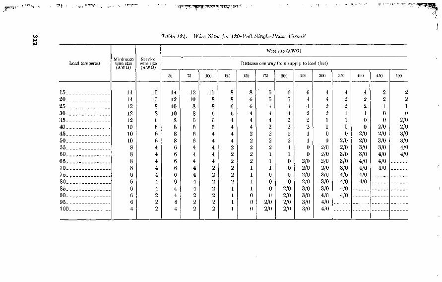
322
IT™' JBÏÏ i ' . » 'r,r**0, ’ - qf" y»ijf-l^g^iTCST . r . v'-'T-ni'
Table 124- Wire Sizes fur 120-Vull Sinyle-Phase Circuil
Wire size (AWO)
Load (amperes)
15..
20..
25..
30..
35. _
40..
45..
50..
55..
60..
65..
70..
75..
80..
85..
90..
95..
100.
Minimum wire size (AWQ)
14 14 12 12 12 10 10 10 8 8 8 8 6
Service wire size (AWO)
10 10 8 8 6 6 6 6 4 4 4 4 4 4 4 2 2 2
Distance one way from supply to load (feet)
50
14 12
10 10 8 8 8 8 6 6 6 6 6 6 4 4 4 4
75
12 10 8 8 6 6 6 6
4 4 4 4 4 4 4 2 2
2
100
10 8
8
6
6
6
4 4 4 4 4 2
2
2
2
2 2
2
150
8
8
6
6
4 4 4 4 2
2
2
2
2
2
1
1
1
1
8
6
6
4 4 4 2
2
2
2
2
1
1
1
1
0
0
0
6
6
4 4 4 2
2
2
2
1
1
1
0
0
0
0
2/0 2/0
200
6
6
4 4 2 2
2
2
1
1
0
0
0
0
2/0 2/0 2/0 2/0
250
6
4 4 2 2 2
1
1
0
0
2/0 2/0 2/0 2/0 3/0 3/0 3/0 3/0
300
4 4 2 2 1
1
0
0
2/0 2/0 2/0 2/0 3/0 3/0 3/0 4/0 4/0 4/0
350
4 2 2 1
1
0
0
2/0 2/0 3/0 3/0 3/0 4/0 4/0 4/0 4/0
400
4 2 2 1
0
0
2/0 2/0 3/0 3/0 4/0 4/0 4/0 4/0
450
2 2 1
0
0
2/0 2/0 3/0 3/0 4/0 4/0 4/0
500
0
2/0 2/0 3/0 3/0 4/0 4/0

323
Table 185. Wire Sizes for 880-Volt 3-Phase Circuits
Load (amperes)
15.. 20. .
25.. 30.. 35.. 40.. 45.. 50.. 55. . 60.. 65.. 70.. 75.. 80.. 85.. 90.. 95.. 100.
125. 150. 175. 200.
225. 250. 275. 300. 325.
Minlmum wire size (AWG)
14 14 12
12 12 10 10 10 8 8 8 8 6 6 6 6 6 4 4 2 2 1 0
2/0 3/0 3/0 4/0
Service wire size (AWO)
12 10 8 8 8 6 6 6 6 6 4 4 4 4 4 4 4 2 2 2 1 0 0
2/0 3/0 3/0 4/0
Wire size (AWO)
Distance one way from supply to load (feet)
100
14 12 10 10 10 8 8 8 8 6 6 6 6 6 6 6 6 4 4 2 2 1 0
2/0 3/0 3/0 4/0
150
12 10
8 8 8 6 6 6 6 6 4 4 4 4 4 4 4 2 2 2 1 0 0
2/0 3/0 3/0 4/0
200
10 8 8 6 6 6 6 4 4 4 4 4 2 2 2 2 2 2 1 0 0
2/0 2/0 3/0 3/0 4/0
250
8 8 6 6 6 4 4 4 4 2 2 2 2 2 2 2 1 1 0
2/0 2/0 3/0 3/0 4/0 4/0
300
8 6 6 6 4 4 4 2 2 2
2 2 2 1 1 1 1 0
2/0 2/0 3/0 4/0 4/0
350
8 6 6 4 4 4 2 2 2
2 2 1 l 1 0 0 0 0
2/0 3/0 4/0 4/0
400
6 6 4 4 4 2 2 2 2 1 1 1 0 0 0 0
2/0 2/0 3/0 4/0 4/0
500
6 4 4 2 2 1 2 1 1 0 0 0
2/0 2/0 2/0 2/0 3/0 3/0 4/0
600
6 4 2 2 2 1 1 0 0 0
2/0 2/0 2/0 3/0 3/0 3/0 3/0 4/0
700
4 2 2 2 1 1 0 0
2/0 2/0 2/0 3/0 3/0 3/0 4/0 4/0 4/0 4/0
800
4 2 2 1 1 0 0
2/0 2/0 3/0 3/0 3/0 4/0 4/0 4/0 4/0
900
4 2 2 1 0 0
2/0 2/0 3/0 3/0 3/0 4/0 4/0 4/0
1,000
2 2 1 0 0
2/0 2/0 3/0 3/0 4/0 4/0 4/0

324 Tabic 126. Wire Sizes for 240-Voll Simjlc-Phase Cireails
Koad (amperes)
15.. 20..
25.. 30.. 35.. 40.. 45.. 50.. 55.. 60.. 65.. 70.. 75-, 80.. 85.. 90.. 95.. 100.
125. 150. 175. 200.
225. 250. 275.. 300. 325.
Minimum wire size (AWO)
14 14 12 12 12 10 10 10
8 8 8 8 6 6 6 6 6 4 4 2 2 1
1/0 2/0 3/0 3/0 4/0
Service wire size (AWO)
10 10
8 8 6 6 6 6 4 4 4 4 4 4 4 2 2 2 2 1 0 0
2/0 2/0 3/0 3/0 4/0
Wire size (AWO)
Distance one way from supply to load (feet)
100
14 12 10 10 8 8 8 8
■ 6 6 6 6 6 6 4 4 4 4 4 2 2 1
1/0 2/0 3/0 3/0 4/0
150
12 10
8 8 6 6 6 6 4 4 4 4 4 4 4 2 2 2 2 1 0 0
2/0 2/0 3/0 3/0 'I/O
200
10 8 8 6 6 6 4 4 4 4 4 2 2 2 2 2 2 2 1 0
2/0 2/0 3/0 3/0 4/0 4/0
250
9 8 6 6 4 4 4 4 2 2 2 2 2 2 1 1 1 1 0
2/0 3/0 3/0 4/0 4/0
300
8 6 6 4 4 4 2
. 2 2 2 2 1 1 1 1 0 0 0
2/0 3/0 4/0 4/0
350
6 6 4 4 4 2 2 2 2 1 1 1 0 0 0 0
2/0 2/0 3/0 4/0 4/0
400
6 6 4 4
■ 2 2 2 2 1 1 0 0 0 0
2/0 2/0 2/0 2/0 3/0 4/0
500
6 4 4 2 2 2 1 1 0 0
2/0 0
2/0 2/0 3/0 3/0 3/0 3/0 4/0
GOO
0 0
2/0 2/0 2/0 2/0 3/0 3/0 3/0 4/0 4/0 4/0
700
4 2 2 1 1 0 0
2/0 2/0 3/0 3/0 3/0 4/0 4/0 4/0 4/0
800
4 2 2 1 0 0
2/0 2/0 3/0 3/0 4/0 4/0 4/0 4/0
ooo
2 2 1 0 0
2/0 2/0 3/0 3/0 4/0 4/0 4/0
1,000
2 2 1 0
2/0 2/0 3/0 3/0 4/0 4/0

1 29. Incandescent Lamp Data
Table 127. Incandescent Lamps
Volts Bulb type 1 Bulb finish Base Rated life- hours
Purpose
10_ 15- 25. 25. 25. 25. 40- 50.
50-__ 60--. 100-. 100. . 150-. 200 ..
200-.
300. . 300-. 500.. 500-. 750.. 1.000. 1,500_
120 120 120 120 120 220 120 120
230 120 120 220 120 120 230 120 120 120 230 120 120 120
S-14 A-15 A-19 A-19 T-10 A-19 A-19 A-19
A-19 A-19 A-21 A-23 PS-25 PS-30 PS-30 PS-35 PS-35 PS-40 PS-40 PS-52 PS-52 PS-52
Inside frost Inside frost Inside frost Ruby Clear Inside frost Inside frost Rough service.
Inside Inside Inside Inside Inside Inside Inside Inside Inside Inside Inside Inside I nside Inside
frost. frost. frost. frost- frost, frost. frost, frost. frost. frost. frost. frost- frost- frost.
Medium. Medium. Medium. Medium. Mediuni Mediu m. Medium. Mediu m.
Medium. Mediu m_ Mediu ni- Medium. Medium. Medium. Medium. Medium. Mogul. . Mogul. _ Mogul. - Mogul- _ Mogul. _ Mogul. _
1, 500 1, 200 1, 000 1, 000 1, 000 1, 000 1, 000 1, 000
1, 000 1, 000
750 750 750 750 750 750
1, 000 1, 000 1, 000 1, 000 1,000 1, 000
General. General. General. Photography. Showcase. General. General. Automotive,
mechanics, etc.
General. General. General. General. General. General. General. General. General. General. General. General. General. General.
1 Stocked in theaters of operations.
130. Lighting in Theater-of-Operations Construction Where facilities permit, the following wattages are suggested for
lighting in theater-of-operations buildings. Watts per square foot
of floor area
Barracks, quarters 0. 10 Storage, wards, heater, toilets, warehouses ■ 20 Messhalls, waiting, and living spaces . 30 Recreation, bathhouses, kitchens, general work spaces, noncritical .50 Reading, laboratories, barber, tailor, post exchange, pharmacy, work
spaces • 75 Offices, laundry, shops—low mounting heights up to 10 feet (repair or
production) 1.00
131. Miscellaneous Electrical Data a. Number of Insulated Wires Allowed in Various Sized Conduits.
See table 128. b. Number of conductors in a box.
(1) Table 129 gives the maximum number of conductors, not counting fixture wires, permitted in outlet and junction
325

boxes. This table applies where no fittings or devices, such as fixture studs, cable clamps, hickeys, switches, or recep- tacles are contained in the box. Where one or more fixture studs, cable clamps, or hickeys are contained in the box, the number of conductors shall be one less than shown in the tables, with a further deduction of one conductor for one or several flush devices mounted on the same strap. A conductor running through the box is counted as one con- ductor and each conductor originating outside the box and terminating inside the box is counted as one conductor. Conductors of which no part leaves the box are not to be counted in the above computation. If single flush boxes are ganged, and each section is occupied by a flush device or combination of flush devices on the same strap, the limita- tions will apply to each section individually.
(2) Table 130 applies for combinations not shown in table 129. c. Full-load Current and Circuit-breaker Sizes for Alternating-current
Motors. See table 130.
Table 128. Number of Insulated Wires Allowed in Various Sized Conduits
Size AWG MCM
18-..
16...
14.. .
12.. .
10_-_
8 6 4
3
2 1 0
00...
000..
0000.
250. _
300..
350..
400..
500..
'A
A y2 A A lA 3A 3A %
l l i IX IX IK IK IK IK
Number of conductors in one conduit or tubing
K K A A 3A X
1 IK IK IK IK IK 2 2 2
2K 2K 3 3 3
K K K K X X
1 IK IK IK IK 2 2 2 2K 2K 2K 3 3 3
K K K X X
1 IK IK IK 2 2 2 2K 2K 3 3 3
3K 3K 3K
K K X 3A
1 IK IK IK 2 2 2K 2K 2K 3 3 3 3K 3K 4 4
K ?
i 1 IK IK 2 2 2 2K 2K 3 3 3 3K 4 4 4 5
K X
i i 1 IK 2 2 2 2K 2K 3 3 3 3K 4 4 5 5 5
X 3A
l 1 IK IK 2 2
2K 2K 3 3 3 3K 3K 4 5 5 5 5
X X
1 IK IK IK 2 2K 2K 2K 3 3 3K 3K 4 5 5 5 5 6
326

Table 129. Number of Conductors Allowed in Boxes of Certain Sizes
Deep boxes
Maximum number of conductors Box dimensions—Trade size .
1^2 x 3!4 octagonal x 4 octagonal., x 4 square
-1J4 x 4 square 1/4 x 4‘J46 square. 2ya x 4'}'ío square. 2 x IK x 2%
2H x IK x 2K 3 x IK x 2K
No. 14 No. 12 No. 10 No. 8
5 8 9
11 16 20
5 6 7
5 7 7 9
12 16 4 6 7
4 6 6 7
10 12 4 5 6
0 5 4 5 8
10
Where there is not sufficient space for a deeper box, four No. 14 AWG conductors may enter a box provided with cable clamps and contain- ing one or more devices on a single mounting strap.
Shallow Boxes of Less Than lYf Depth
Box dimensions—Trade size
3K-- 4 4
1KB-
Maximum number of conductors
No. 14 No. 12 No. 10
Table ISO. Number of Conductors Allowed in Boxes, Other Combinations
Size of conductor Free space within box for each conductor
No. 14. No. 12. No. 10. No. 8-
2 cubic inches. 2.25 cubic inches. 2.5 cubic inches. 3 cubic inches.
327

Table 131, Full-Load Current and Circuit-Breaker Sizes for Alternating-Current Motors
Motor horsepower
Slagle phase
110 volt
Current (amps)
Circuit- breaker
size (amps)
220 volt
Current (amps)
Circuit- breaker
size (amps)
Three phase
220 volt
Current (amps)
Circuit- breaker
size (amps)
440 volt
Current (amps)
Circuit- breaker
size (amps)
V*-
K-
l—
1/2-
3 5
7X- 10-.
15—
20„
25..
30-
40—
50-
60-.
75-
100-
3. 34 4. 8 7 9. 4
11 15. 2 20 28 46 68 86
15 15 15 25 25 35 50 50 70
125 200
1. 67 2. 4 3. 5 4. 7 5. 5 7. 6
10 14 23 34 43
15 15 15 15 15 25 25 35 50 70 70
2. 5 2. 8 3. 3 4. 7 6 9
15 22 27 38 52 64 77
101 125 149 180 246
15 15 15 15 15 25 35 50 50 70
125 125 125 200 200 225 400 400
1. 3 1. 4 1. 7 2. 4 3 4. 5 7. 5
11 14 19 26 32 39 51 63 75 90
123
15 15 15 15 15 15 15 25 35 50 70 70 70
125 125 125 200 200
Section V. SPECIAL UTILITIES
1 32. Refrigerated Warehouses a. General. Table 132 gives basic data on T/O refrigerated ware-
hoiises. For further details see TM 5-302. b. Types and Capacities. For preliminary planning in areas where
refrigerated storage is needed primarily for frozen meat, a storage capacity of 0.02 cubic feet per man per day is satisfactory. For storing all components of the field ration, at least three compartments are needed; one for frozen meat because of the low temperature re- quired, one for butter and shelled eggs because they are contaminated easily by other foods, and one for smoked meats, fruits, and vegetables. The controls are normally operated to maintain temperatures of 10° F. for frozen meat and 34° F. for other foods.
c. Illustrative Situations. (1) Problem. To select refrigerated warehouse capacity suitable
for 30-day storage of rations for 20,000 men.
328

(2) Solution. This is equivalent to 60-day storage for 10,000 men. Table 132 shows that the following are adequate—
Rations {men fnr 60 days)
For frozen beef, 2 warehouses 20' x lOCK 11, 880 For butter and shelled eggs, 1 warehouse 20' x 100' 10, 560 All other items:
4 warehouses 20' x 100' 9, 520 1 warehouse 20' x 55' 1, 080
Table 182. Sizes and Capacities of T/O Refrigerated Warehouses, Standard Frame
Nominal size
Inside dimensions (feet) Gross floor area (square feet). _ Ceiling height (feet) Height of stack (feet) Equipment
20' x 55'
18' X 40' 720 8 6 2 compressors
(20,000 B.t.u. per hour).
1 evap con- denser.
1 cooling tower. 2 unit coolers.
20' x 100'
18' x 88' 1,584... 8 6 2 compressors
(40,000 B.t.u. per hour).
1 evap con- denser.
1 cooling tower . 4 unit coolers .
80' x 220'
77.5' x 197' 15,267 14.5 12 1 compressor
(78,000 B.t.u. per hour).
2 compressors (180,000 B.t.u. per hour).
1 evap con- denser.
1 receiver. 20 unit coolers.
Storage capacity
Frozen packaged boned beef: Total pounds Total rations Men for 60 days
Butter and shelled eggs: Total pounds, butter Total pounds, eggs Total combined rations Men for 60 days
Ham, bacon, bologna, pota- toes, onions, and citrus fruits.1
81,000. 162,000 2,700. _
36.000. 36.000. 288,000 4.800..
178,200 356,400 5,940..
79.200. 79.200. 633,600 10,560-
Total pounds, ham, bacon and bologna.
Total pounds, other items. Total combined rations ... Men for 60 days
10,200.
45,500. 65.000. 1.080..
22,440..
100,030. 142,900. 2,380.-.
• Equal rations of each item.
329

330
"•r .v _ ytl. '“T- >-r T».' •'V'Vf -.» ry ^"- ^ .'f -«”»■ ’ ' ' Í ^ . ‘ ’,' '4
133. Refriserant Properties Table 1SS. Refrigerant Properlies
Critical temperature. Flammability
Effect on metals.
Effect on lubricants.
Effect on personnel .
Tests for leaks.
Ammonia (NH3)
271° F Burns if heated. May ex-
plode under certain condi- tions.
Reacts with copper and brass if water vapor is present. Slight effect on iron and steel.
No effect if ammonia is an- hydrous. If moisture is present, tends to form emulsion.
Injurious if exposure is pro- longed and gas concentra- tion is above Yso of 1 per- cent. Very irritating to eyes and nose.
By smell. Exact location found with sulfur candles.1
Freon (F-12) (CCIJFJ) Freon (F-22) CJiClF2
233° F Non dam niable and
nonexplosive.
Noncorrosive
No effect. Mixes with oil in all proportions.
Practically non- toxic.
00-
204.8° F Nonflammable and
noncxplosive.
Noncorrosive
No effect. Mixes with oil in all proportions.
Practically non- toxic.
(2)-
Mothyl chloride (CHjCl)
290° F. Flammable but does not burn
readily. Explosive under certain conditions.
Noncorrosive.
Dissolves all kinds of oil. Glycerine and white mineral oils must be used.
Concentration of 2 percent to 2Y percent for 2 hours may cause death.
Smells like chloroform. Alcohol flame in methyl chloride has greenish tinge.
7 r/~-
■ Forms white log when burned in presence of ammonia. 2 Halide lamp usually used. This consists of a flame-heated copper wire which in contact with freon burns with a blue-green color.

134. Iceplant Characteristics Table 1S4- Ice-plants
Stock No.
Weight (pounds crated for export) Cubage (cubic feet crated for export). Connected electrical load
l-ton
66-5710.01-0
10, 200 427
None
3.6-ton
66-5710.06-0
27, 500 1, 314
12.24 kv.-a.
11.40 kv.-a.
66-5710. 15-0
120, 600 4, 950 57. 76
55. 26
135. Air Conditioning a. Authorized Uses. In tropical climates air conditioning is used
in hospitals or installations to protect patients or mechanical equip- ment from excess heat and humidity. Its use is not authorized to provide comfort for personnel in normal health even though it might increase efficiency. Air conditioning is used in all climates for certain photographic reproduction processes and for the repair and adjustment of instruments; for example, some types of radar and bombsight equipment require controlled temperature and humidity.
b. Standard Unit. The standard Army air-conditioning unit developed for use in theater-of-opcrations construction is self-con- tained, water-cooled, and powered by a 5-horsepower motor. It has a capacity of 70,000 British thermal units per hour. In tropical temperatures, one unit will air-condition a space 20 by 20 feet (or equivalent) with 100 percent fresh-cooled air, or a space 20 by 40 feet (or equivalent) with 33 percent fresh air and .67 percent recon- ditioned air. The unit consists of an air-handling cabinet 8 feet high 4 feet wide, and 1 foot 8 inches deep and a cooling tower 8 feet high, 4 feet wide, and 2 feet 6 inches deep. The shipping weight and cubage of both items are 3,745 pounds and 206 cubic feet.
1 36. Boilers and Accessories a. Types and Rating.
Type
Vertical steel fire tube
Horizontal steel fire tube Portable steel firebox
Rating (boiler horse-
power)
15 25 35 60
200 143
331

b. Other data.
Table 135. Dala on Boiler Feed Pumps
Size
Minimum capacity of pump, (gallons per minute)
Maximum piston speed (feet per minute) Size of steam inlet (inches) Size of exhaust outlet (inches) Size of water suction (inches) Size of water discharge (inches) Weight, crated for export (pounds) Cubage, crated for export (cubic feet)
3x2x3
6 14
350 5
iÿi x 3 x 4
10 20
Vt 2 2
3A 400
7
5M x 314 x 5
25 25
J! 2 2 2
600 10
Table 136. Data on Feed-Water Heaters
Coil surface (sq. ft.) minimum
Condensing capacity (pounds per hour) Water flow (gallons per minute) minimum__ Steam-supply connection (inches) Condensate connection (inches) Water inlet and outlet (inches) Safety valve (inches) Connections to oil separator (inches) Grease trap, inlet and outlet (inches) Float and thermostatic trap inlet and outlet
(inches) Weight, crated for export (pounds) Cubage, crated for export (cubic feet)
20
100 6
225 9
30
160 10
2
y* 3A
250 11
75
400 25
2 %
22 iy2 2
325 13
Table 137. Data on Surge Tanks
Capacity (gal) 185
Tank dimensions Installed position Condensate return connection (inches)-. Feed-water connection (inches) Vent connection (inches) Pump suction connection (inches) Drain connection (inches) Weight, crated for export (pounds) Cubage, crated for export (cubic feet)
24 by 42 Horizon tal
2 3A
2 2
3A 560
18
24 by 72 Horizontal
2 3A
2 2
y* 800
25
30 by 60 Vertical
2
% 2 2
% 900 30
332

Table 188. Dala on Storage Type Hol-Waler Generators
Storage capacity (gal) 750
Diameter of shell (inches) Length of shell (inches) Shell thickness (inches) minimum Coil heating surfaöe (square feet)
minimum Tappings for hot- and cold-water con-
nections (inches) Tappings for steam, condensate, re-
lief, and drain connections (inches)-- Comínnation temperature and pres-
sure-relief valve (capacity in Brit- ishthermal units)
Size of temperature regulating valve (inches)
Weight, crated for export (pounds)-I-- Cubage, crated for export (cubic feet).
48 96
0. 312
33
1 4
2
1, 000, 000
2, 250 112
36 84
0. 250
10
2
2
300, 000
1 1, 700
86
30 72
0. 187
5
2
2
300, 000
1, 200 60
1 Four-inch connections are flanged with threaded cast-iron companion flanges and necessary nuts, bolts, and gaskets.
Table 189. Data on Boilers
Stock No. Item
4410-277-3139
4410-277-5871
4410-277-3147
Boiler, steam, high pressure, horizontal; horsepower not rated, 400 lb. steam; forced or induced draft, oil fired.
Boiler, steam, high pressure, horizontal; 200 hp., 6,900 lb. steam; forced draft; oil fired, w/27 accessories.
Boiler, steam, high pressure, vertical; 60 hp., steam delivery not rated; induced draft, coal fired, hand, or oil fired.
137. Steam Generators Table H0. Steam Generators
Rating pounds of steam per hour 400
4, 000 160
10
200
Weight, crated for export (pounds) Cubage, crated for export (cubic feet) Condensate pump (gallons per minute) Condensate receiver, capacity (gallons) Oil burner (gallons per hour at rated capacity)- Connections (inches):
Condensate return Make-up water Blowoff (blowdown) Steam supply
Motor, fan (horsepower) Motor, condensate pump (horsepower)
3, 000 120
V/
10 2
% % %
333

33
4
piSwyHy-. 1 'f--”' T" T
138. Utilities Requirements of Mess Buildings Table HI. Mess Buildimj Utilities
Hospital
Size: Seating capacity Feeding capacity Kitchen feeding (maxi-
mum) capacity TO number, TM 5-280...
Climate Equipment:
Range, cooking Bain marie, 72" by 36". Water heater, 50-gal.
per hour (58° F. rise). Range boiler, 82-gal Hot-water generator, 10
sq. ft., 330-gal Hot-water generator, 5
sq. ft., 220-gal Refrigerator, US No. 20. Refrigerator, US No.
45 2 Dishwasher, 180-DA Dishwasher, 50-SM
Troop Patients (1,000- and
TñO-bcd)
120 170
»170 11. 10A
Temp
2
256 300
1, 000 35. 17
sheet 1 Temp
10 1
Patients (500- and 250-bed)
224 300
500 35. 17
sheet 2 Temp
(100 -'-bed)
112 280
280 35. 17
sheet 3 Temp
Detachment (1,000- and 750-bed)
224 300
500 35. 17
sheet 4 Temp
Detachment (500-bcd)
176 280
280 35. 17
sheet 5 Temp
Odiccrs and nurses (1,000- and 750-bed)
168 280
280 35. 17
sheet 6 Temp
3 1
1
3 1
Officers and nurses
(250-bed)
56 112
170 35. 17
sheet 7 Temp
(500-bed)
96 170
170
3 1

533506
o o
CJ U Ui
Steam generator 4 (self- contained) 200-lb. per hour
Steam generator 4 (self- contained) 400-lb. per hour
Power: Basic plan 1 (with dish-
washer) i Light . Power
Total kilovolt- amperes
Alternate plan 1 (with- out dishwasher)
Light Power Total kilovolt-
amperes Water consumption 7
(estimated) : Gallons per day (maxi-
mum) with hand washer (alternate plan)
Gallons per day (maxi- mum) with machine washing (basic plan).
(5)
0. 90
0. 90
3, 100
2. 49 2. 80
5. 29
2. 49
2. 49
18, 000
15, 000
2. 09 2. 80
4. 89
2. 09 0. 60
2. 69
9, 000
7, 500
0. 81 2. 50
3. 31
0. 81 0. 30
1. 11
5, 000
4, 200
(5)
1. 58 0. 30
1. 88
9, 000
1. 38 0. 30
1. 68
(°)
4, 200
1. 22 2. 80
4. 02
1. 22
1. 22
5, 000
0. 71 2. 80
3. 51
0. 71
0. 71
3, 100
4, 200 2, 600
0. 81 2. 80
3. 61
0. 81
0. 81
3, 100
2, 600
1 See TM 5-3U2 for layout and drawings. 2 Replaced with US 05 refrigerator. 3 Same as type A, 2,000-plate dishwasher. 4 See par. 137. * No basic plan.
0 No alternate plan. ' Based on 0 gal. per person per day with hand dishwashing and 5 gal. per person per
day with machine dishwashing. 8 iror patients, detachment, olliccrs, and nurses. 8 Capacity based on use of heavy-duty ranges.

CHAPTER 9
STRUCTURAL DESIGN DATA
Section I. DESIGN LOADS 1 39. General
This chapter provides data for the design or classification of non- standard fixed bridges, buildings, and similar structures required for temporary use in theaters of operation, based on the use of standard or commercial, construction materials. The data for wind loads and impact loads on bridges has been simplified so as to eliminate many factors normally considered in bridge design. For bridge structures of a more permanent type, refer to the latest editions of The American Association of State Highway Officials, Standard Specifications for Highway Bridges, and American Railway Engineering Association Specifications. For designs based on materials differing from those in general use in the United States, modifications in values of working stresses may be required. Safe loads for standard and prefabricated bridges and buildings are given elsewhere in this text or in appropriate technical manuals. In general, information on structural design of the various materials is simplified and elementary, and does not point out all the details to be considered in making designs. It is intended to be used under the guidance of persons with enough experience in design to recognize this.
140. Dead Loads a. General. The weights of the elements of a structure are com-
puted and combined as required for the design of each structural member. Utilities, such as water tanks, which are an integral part of a structure are included in dead loads. Structural members are designed using assumed values for their own weights, then rede- signed if necessary.
b. Highway Bridge Floor and Stringers. Tables 142, 143, and 144 give dead load in pounds per linear foot of bridge, for three types of bridge.
c. Wood-Rooj Trusses. Preliminary allowances for the weight of wood-roof trusses, in pounds per square foot of horizontal projection of the area supported, are:
(1) Pitched trusses, 0.064 L. (2) Flat-top Pratt trusses, 0.043 L-i-1.75. (3) Bowstring trusses, 0.038 Z-^0.60.
Where Z=span of truss in feet.
336

Table 14%- Dead Load in Pounds Per Pçul of Bridge—6-Inch Timber Floor with Timber Stringers, Curb, and Railing
Class Type
8 Single-lane 14'-roadway_. Double-lane 24'-roadway_
24 Single-lane 14'-roadway. _ Double-lane 24'-roadway_
70 Single-lane 14'-roadway_ _ Double-lane 24'-road\vay _
Span in feet
400 640 460 730 500 840
410 650 470 750 530 880
410 660 480 770 560 030
420 670 400 700 580 070
420 680 500 810 610
1, 020
430 600 510 820 640
1, 050
430 600 510 840 660
1, 000
2Ü
440 700 520 860 600
1, 130
440 710 530 880 720
1, 170
22
450 720 540 900 740
1, 220
2a
450 730 550 920 770
1, 260
460 740 560 930 800
1, 300
460 740 560 950 820
1, 340
Table 14S. Dead Load in Pounds Per Fool of Bridge—Slcel Stringers with 6-Inch Timber Fluor—Timber Curb, and Railing
Class
8..
24.
70.
Type
Single-lane 14'-roadway.. Double-lane 24'-roadway_ Single-lane 14'-road\vay_. Double-lane 24'-roadway_ Single-lane 14'-roadway. _ Double-lane 24'-road\vay.
480 770 570 940 650
,050
au
520 840 620
1, 010 • 740 1, 210
Spun in feet
560 900 660
1, 080 830
1, 370
600 970 710
1, 150 920
1, 530
CPO
630 1, 030
750 1, 220 1, 010 1, 690
670 1, 100
800 1, 290 1, 100 1, 850
8U
710 1, 160
840 1, 360 1, 190 2, 010
DO
750 1, 220
890 1, 430 1, 280 2, 170
100
780 1, 280
930 1, 500 1, 370 2, 320

Table 144- Dead Load in Pounds Per Foot of Bridge—Steel Stringers with 6-Inch Concrete Floor and Concrete Curb—Timber Railing
Class Typo Span in feet
30 40 00 80 90 100
8 Single-lane 14'-roadway_. Double-lane 24'-roadway_
24 Single-lane 14'-roadvvay.. Double-lane 24'-roadway.
70 Single-lane 14'-roadway_. Double-lane 24'-roadway_
1, 500 2, 250 1, 580 2, 360 1, 660 2, 480
1, 560 2, 330 1, 650 2, 480 1, 770 2, 680
1, 610 2, 400 1, 720 2, 590 1, 880 2, 880
1, 670 2, 480 1, 790 2, 700 1, 980 3, 080
1, 720 2, 550 1, 860 2, 810 2, 100 3, 270
1, 780 2, 630 1, 930 2, 920 2, 210 3, 470
1, 830 2, 700 2, 000 3, 030 2, 320 3, 670
1, 880 2, 780 2, 070 3, 140 2, 430 3, 870
1, 930 2, 850 2, 140 3, 250 2, 540 4, 060

d. Steel-Roof Trusses.
w= — s : 150+5L+^
Where w= weight of truss in pounds per square foot of horizontal projection of the area supported.
p=total load in pounds per square foot of horizontal pro- jection of the area supported.
L=span of truss in feet.
S=spacing of trusses in feet.
e. Weights of Materials. The weights of materials, given for estimating live loads in paragraph 141 and others given in chapter 10, are also useful in estimating dead loads of structures.
141. Live Loads a. Highway Bridges. Each highway bridge is posted to indicate
the class of vehicles that can make a normal crossing under the follow- ing conditions: Vehicle traveling in designated lane; maximum speed for critical vehicles 25 miles per hour; no sudden stopping or accelera- tion; vehicles 25 miles per hour; no sudden stopping or acceleration; vehicles spaced at least 30 yards tail to head. The loading applies to each lane for bridges more than one lane wide. Maximum shears and reactions normally occur when one vehicle per lane has its rear axle just over the gap side of an abutment or pier; maximum moment occurs when one vehicle per lane is near the center of the span. To determine the moment and sheaf caused by the design class vehicle, use the charts in figure 67 (1) through (7). These values are for one- lane, and should be doubled for two-lane bridges. Also, duo to the non-uniform lateral distribution of loads through the axles or tracks of military vehicles, a lateral distribution factor of 1.5 is applied to live and impact loads in designing bridge members for moment, shear, and bearing. Allowable deflection for military highway bridge is %i5 of the span.
b. Railroad Bridges. Cooper’s E-45 loading (fig. 68) is used in design. The moments, shears, and pier reactions produced by this loading, for each rail, are tabulated in paragraph 148. The table also gives equivalent uniform loads, per rail, for each span length.
c. Floor Loads for Buildings. (1) Uniformly distributed loads. (2) Weights of materials. Assuming normal aisles and working
spaces, the weights of various materials which are used in estimating warehouse live loads are shown in table 146.
339

BE
ND
ING
MO
ME
NT -
FO
OT
TO
NS
7
200
<ri œ
z o z
H Z Ui S o 5
¿SS*
0 5 10 15 m ccvkiiMH vira araa*« tan eoavaa« »ir .m.» —...■m¡im¡miiT||imy«i« SPAN LENGTH-FEET
Figure 67(1). Standard class curves (moment) O'-SO1 spans.
340

BE
ND
ING
MO
ME
NT
- F
OO
T
TO
NS
I2Û
34
33
32
30
29
28
27
26
25
24
23
m 22
Ö2 I 20
9 Z5£ H I 8
I 7
I 6
I 4
3S ¿fio z
10
ÍÜ 40 45 50 60
" tM« iu*ra in MIT
Figure 67(2). Standard class curves (moment) 20'-60' spans.
341

BE
ND
ING
MO
ME
NT
-FO
OT
TO
NS
X80
MOO O
?70
m *60
iso
o 0
100 160 220 240 120 200
m eowesiew «m «TA«*« ••ti'evava*
BT SPAN LENGTH-FEET
Figure 67(3). Standard class curves (moment) 60’-260' spans.
342
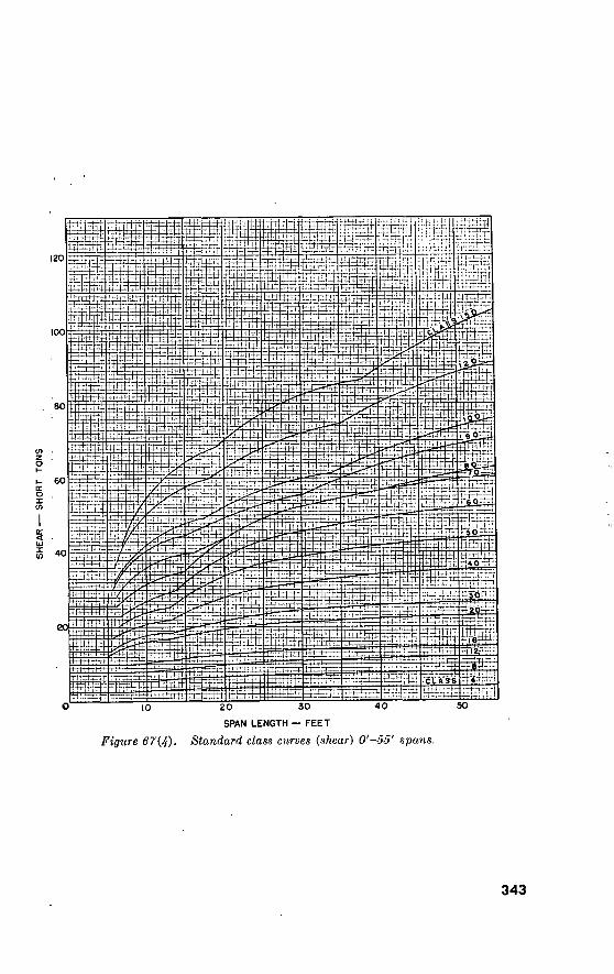
(00
Z . 4 B 0-1
60
Ti*j
50
40
HSffit
ci; à 5S
50 20 30
SPAN LENGTH — FEET
Figure 67U). Standard class curves (shear) O'-55' spans.
343

SH
EA
R—
SH
OR
T
TO
NS
220
200
180
160
140
20
80 SP 60
40
H TTir, i;
20
55 TO 105 I3Ó 155 ¡15 205 SÖ 255 280
SPAN LENGTH—FEET
Figure 67(5). Standard class curves (shear) 55'-280' spans.
344
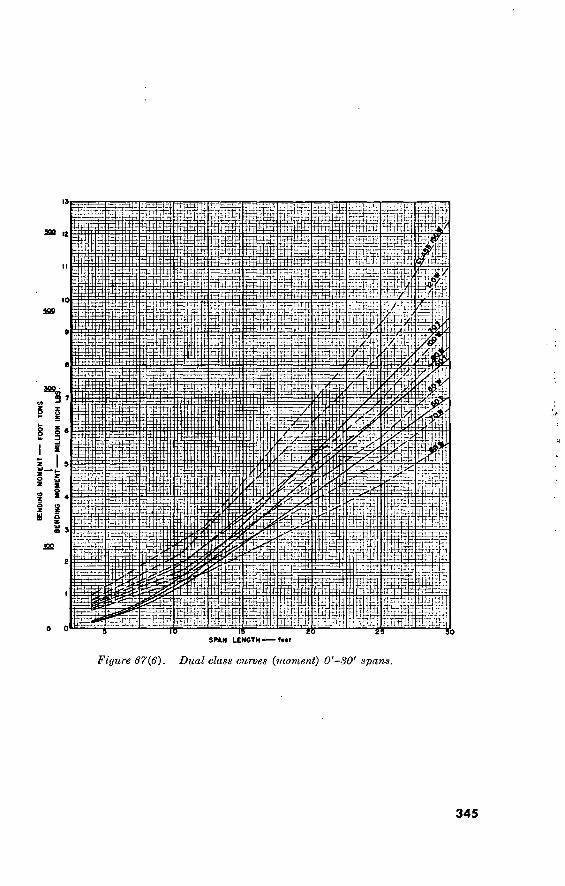
BE
ND
ING
MO
ME
NT
MIL
LIO
N
INC
H
i ’•LG
52
rzfr.r/ 2 oS
¿á
if:? v£
JfiB
=A
it ~ttr SPAH LENGTH fMf
Figure 67(fi). Dual class curves (moment) O'-30' spans.
345

H/
G'-»,
l ioy.1 'jrr--
i?2i
s*ei
40 90 60 70
SPAN LENGTH— feet
1 I. DETERMIN£ THE MAXIMUM HOHIHT CAKRYIM9 CARAOITY (USISTIMA MOMENT) OP THE BNIO«E TO BE CLABBIPIEO.
t DRAW A HORIZONTAL UNE THROUOH THE VALUE RERREBENTMB THIS MOMENT ANDA VERTICAL LINE THROUBH THE
BRAN LENOTH USED AND NOTE THE ROINT OR INTERSECTION.
S THE DUAL CLABSIRICATION NUMBER OR THE BRIDBE IS THEN DETERMINED BY USINB THE DASHED LINES
RON WHEELED VEHICLES AND THS BOUD LINES ROR TRACKED VEHICLES.
Figure 67(7). Dual class curves (moment) SO'—100' spans.
346

(O
29250
29250
22500
29250
29250
29250
29250
I- II
Figure 68. Bridge live load equivalents.
347

Table 145. Uniformly Distributed Loads
Use or occupancy Live load in pounds ' per square foot
Barracks and small mess and assembly buildings Offices Hospital operating rooms Mess and assembly rooms with fixed seats.L
Other assembly rooms and gymnasiums Garages, passenger cars only Garages, trucks, less than 3 tons including load. Garages, trucks, 3 to 10 tons including load Garages, trucks, over 10 tons including load Warehouses, light storage Warehouses, heavy storage
40 ■ 50
60 60
100 75
100 150 200
’ 125 = 250
1 If special conditions of use arc indicated, the necessity for using heavier values will be investigated. 2 Minimum for any type of materials-handling equipment. Increase as required for heavy-duty materials-
Iiandling equipment and for high stocking of materials.
(3) Concentrated loads. For office floors, provision is made for a load of 2,000 pounds placed on any space 2% feet square wherever this load upon an otherwise unloaded floor produces stresses greater than those caused by a uniformly distributed load of 50 pounds per square foot. In designing floors in buildings for other purposes, the actual five load caused by the use to which the building is to be put is used in the design of the building or part thereof, and special provision is made for machine or apparatus loads when these result in a greater load than is given in (1) above.
(4) Partition loads. In buildings designed for live loads less than 100 pounds per square foot, an assumed partition load of 300 pounds per linear foot of masonry partition, or the actual computed partition load, if greater, is used in the design. For permanent or semipermanent buildings not initially divided by partitions, allowance is made in live loads on this basis for future partitions.
d. Live-Load Reductions. (1) No live-load reductions are made in roof members nor in
buildings used for assembly purposes. In other buildings designed for live loads of 100 pounds or less per square foot, the design live load on any member carrying 150 square feet or more may be reduced at the rate of 0.08 percent per square foot of area supported by the member. The reduction shall
not exceed 60 percent nor shall it exceed 100 X D+L 4.33 L
where
D is dead load and L is live load, both in pounds per square foot of area supported by the member.
348

Table 146. Material Weights
Material ■
Building materials: Bricks Portland cement Lumber
Painting materials: Linseed oil in drums White lead paste in cans.-
Dry goods: Cotton sheeting, in cases.- Wool, in bales, com-
pressed Groceries:
Canned goods in cases Coffee, roasted, in bags Sugar, in cases
Hardware: Chain Wire, insulated copper, in
coils Wire, galvanized iron, in
coils Miscellaneous:
Tires Books (solidly packed) Paper (newspapers) Rope, in coils Rubber, crude Chinaware, in crates
Weight of material per cu ft of space
(pounds)
Height of pile (feet)
Weight per sq ft of floor
(pound?)
Recommended live load (pounds per square foot)
45 72 to 105
45
45 174
23
48
58 33 51
100
63
74
30 65 35 32 50 40
6 6 6
4 3)(
4M
6 6 6 6 8 8
270 432 to 630
270
180 610
184
348 264 306
600
315
333
180 390 210 192 400 320
300 to
400
200 to 300
200 to
250
250 to
300
300
to
400
> See par. 219 also. (Reprinted from “Steel Construction” by permission of American Institute of Steel Construction, copyright 1947.)
(2) In buildings designed for live loads of more than 100 pounds per square foot, no reductions are made except that live loads on columns may be reduced 20 percent.
142. Roof Live Loads For buildings in locations with climates similar to those of the
three zones into which the United States has been divided for this purpose, roof live loads in pounds per square foot of horizontal projection are given in figure 69.
349

rap
ROOF LIVE LOAD IN POUNDS PER SQUARE FOOT
OF HORIZONTAL PROJECTION.
FOR ROOFS PITCHED MORE THAN 15 DEGREES
(3'/4 INCHES PER FOOT) REDUCE LIVE LOAD
1/3 POUND PER DEGREE OF PITCH.
Figure 69. Roof live loads in the United States.
143. Wind Loads a. Bridges. Short bridges ar© designed with -no allowance for wind.
For bridges of 100-foot span or more, the following wind loads are used in design:
(1) With no live load on bridge, 30 pounds per square foot on 1.5 times the net area of the side elevation.
(2) With full live load, change the above 30 pounds to 15 pounds per square foot on 1.5 times the net area of bridge and load, and increase the allowable live-load stress by 5 percent.
b. Buildings. The wind pressure and suction (uplift) loads normally used in design, in pounds per square foot of vertical projection, are given in table 147. Wind pressure and suction both act in a direction normal to the plane of a wall or roof. Wind-load requirements are developed locally for areas subject to hurricanes or other violent winds.
c. Stress Increases jor Wind Loads. See paragraph 149 for mod- ifications in unit stresses in structural steel, for wind loads alone.
144. Impact Loads No allowance for impact is required for any wood structures, and
normally none is required in any other structures except those designed to carry heavy, moving loads. In steel-bridge structures, live-load stresses are modified for impact and similar factors, as follows:
350

Table 147. Wind Pressures on Buildings
Exterior walls.
Additional load on interior side of exterior walls.
Chimneys .
Flat roofs _ Pitched
roofs.
Load In pounds per square foot of vertical projection
Surface
Temporary buildings not used for as- sembly
Permanent buildings Buildings nominally tight Buildings between tight and 30 percent
open Buildings 30 percent or more open
4.
Pressure Suction
10 20
4. 5 or 4. 5
5 to '12 or 4. 5 to '19 12 or 19
Square or rectangular.. Hexagonal or octagonal Round or elliptical
30 24 18
Wind- Roofs pitched under 20° ward Roofs pitched 20° to 30° side. Roofs pitched 30° to 60°
Roofs pitched 60° and over. Leeward side, all pitches. _
0 to
Ratio- Rise: Run Pressure
12 12
12 to *0
9
Suction
Bowstring roofs.
Starting at ground level.
On ele- vated sup- ports.
Windward J4 of arc
Central J4 of arc. Leeward Yt of arc
Windward ¡4 I arc I
Central J4 of arc. Leeward of arc
0. 0 to 0. 6 any any
0. 0 to 0. 2 0. 2 to 0. 6 0. 2 to 0. 35 0. 0 to 0. 6
any
0 to ‘11. 4
0 to '12 (or)
11 9
12
12 to ' 0 lito ‘20
. 9
» UniTorm rate of increase or decrease.
a. Highway Bridges. For impact, increase stresses by 15 percent of the live-load stress in steel superstructures. No increase is required in substructures.
b. Railroad Bridges. No allowance for impact is required for substructures other than steel towers. For rolling effect in super- structures and steel towers increase stresses 20 percent in the loading from one rail and provide an equal decrease in the loading from the other rail. In addition, for impact, live-load stresses are increased by percentages as follows:
(1) For steam locomotives: L2
(a) Spans-under 100 feet, 7=80—
(b) Spans over 100 feet, 7=^^^Q+30
351
533500°—00 23.
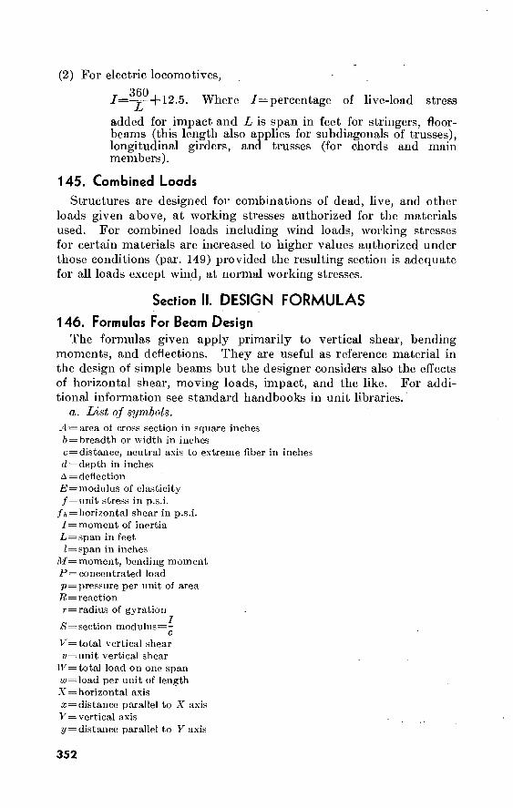
(2) For electric locomotives,
/=360+12 5 Where /= percentage of live-load stress
added for impact and L is span in feet for stringers, floor- beams (this length also applies for subdiagonals of trusses), longitudinal girders, and trusses (for chords and main members).
145. Combined Loads Structures are designed for combinations of dead, live, and other
loads given above, at working stresses authorized for the materials used. For combined loads including wind loads, working stresses for certain materials are increased to higher values authorized under those conditions (par. 149) provided the resulting section is adequate for all loads except wind, at normal working stresses.
Section II. DESIGN FORMULAS
146. Formulas For Beam Desisn The formulas given apply primarily to vertical shear, bending
moments, and deflections. They are useful as reference material in the design of simple beams but the designer considers also the effects of horizontal shear, moving loads, impact, and the like. For addi- tional information see standard handbooks in unit libraries.
a. List oj symbols. ^4 = area of cross section in square inches 6 = breadth or width in inches c = distance, neutral axis to ex'treme fiber in inches d = depth in inches A = deflection £= modulus of elasticity /=unit stress in p.s.i.
/A = horizontal shear in p.s.i. / = moment of inertia
-L = span in feet Z = span in inches
iW= moment, bending moment P= concentrated load p = pressure per unit of area Tt = reaction r = radius of gyration
S = section modulus=- c
V = total vertical shear v = unit vertical shear
TF= total load on one span r« = load per unit of length X = horizontal axis x = distance parallel to X axis K= vertical axis ÿ = distance parallel to Y axis
352

b. Properties of Sections. Areas, moments of inertia, and other properties of selected geometrical shapes are given in figure 70.
c. Beam Formulas for Flexural Stress at Extreme Fiber.'
Mc M f~~T~~S
M——=Sf c J
S=-7=f c /
d. Horizontal Shear Stresses in Beams. (1) Rectangular beams.
Jh~2y<-bd
(2) Steel I beams. V
web thicknessXdepth between curved fillets
(3) Beams of circular cross section.
16V .h= Zird2
e. Reactions, moments, and shears for statical^ loaded beams are given in figure 71.
Beams Without Lateral Support. Long unsupported or unbraced
beams having ^ value greater than 40 are not normally' used as load
carrying members. These beams should be braced or supported to
reduce the value ofZ For investigation of beams where adequate
lateral support is not provided, a reduced extreme fiber stress in bending is computed from the following:
J- 14,400,000
ld^-bt
Where ./= allowable stress in psi ¿=unsupported length in inches 6=flange width in inches i=flange thickness in inches
/. Continuous Beams. For continuous beams with equal spans and uniformly distributed loads, two to five spans, moment and shear coefficients are given in figure 72.
147. Stresses in Rigid Frames
Stresses in rigid frames, for various conditions of static loading, are given in figure 73.
353

Rectangle Axis of moments
through center
d X—
T c
-Lx
A = bd
_ d c ^ 2
i = M" 1 12
bd"
f —2-V_ h - 2 bd
s =
• d VTT = .288675 d
Rectangle Axis of moments any line through center of
-gravity
A = bd
b sin a + d cos a
, bd (b1' sin* a + d~* cos' o) 1 ~ 12
$ = bd fb' sin~ a + dJ cos' a) 6 (b sin a + d cos a) Vb2 sin' a + d’ cos2 a 12
Hollow Rectangle
Axis of moments through center
i d X—
A = bd — bi dt
. _ bd1 - b. di3
1 12
c _ bd1 - bi d.4
5 “ 6d
- -V /bd1 - r V l: bi dr
2A
Equal Rectangles
Axis through' center of gravity A = b (d
i, ..... d d'
J_
, = b (d" - d.J) 1 12
Vd" - d.1
12 (d - d.)
Trapezoid Axis of moments through
center of gravity A = d ,fb + bi)
Lb,-4 _ d (2b + b,) c 1 (b + bi)
• d1 (b" + 4bb, + biJ) 1 - 36 (b + bi)
, _ d3 (b3 + 4bb, + b,3) 5 12 (2b + bi)
r = 6~(L+ b.) "V2 <b'' + 4bb’ +
Figure 70. Properties of sections.
354

Circle Axis through center
d X
A = ^~ = TTR- 4
= 2 = R
= .785398 d' = 3.141593 R-
I =
S =
■rrd* __ irR^
nd* trR1
32
d _ R
.049087 d* = .785398 R'
.098175 d1 = .785398 R*
Ï6V fh —
3 * d*
Hollow Circle
Axis through center
_L d v—
= T,(d-' - dr) = .785398 (d-' - d.-)
yrid* — di*) 64
= .049087 (d‘ - di‘)
S = = v(d' - - 32d~
= .098175 d4 - d.<
•Vd- + d»J
4
Angle Axis through center of gravity
— b —
Y >8"
J
'a9')-
UJtr’-*-
rr
. . /1 ! \ _ b* + ct A _ , (b + c) x - 2 (b + c) 7 - 2 It 4- c)
1
d' *f ot
lx = y [t (d-y)' + by.' - a (y-t)’J
lr = yt (b-x)' T dx' - c (x-t):l]
|y. = |\ sin' 0 + l\ cos' 0 4- K sin 2
I« = |v cos’ 19 *f h sin' ^ — K sin 2
obcdt K = K is negative when heel of ^ TTI1CII IICCI
' ' ongle, with reference to
c. g., is in 1st or 3rd quadrant, positive when in 2d or 4th.
Beams and Channels
Transverse force oblique through c. g.
— 3 3
V
h = lx sins 4 + l\ cos3
It = lx cos' 4 + l\ sin2 ‘«A
f = M sin * + -ji- cos -A)
Where M is bending moment
due to force F
Figure 70—Continued.
355

Simple beom, uniformly distributed load.
*—X
Mmaj
Ï iilfcnw
Jl
Equivalent uniformly distributed load —
MOMENT
R = V
Vx
Mmax {at center)
M>
^>max (at center)
Ax
= w - x)
(i - x)
wZ-
8
wx 2
5wZ4
384EI
^ - 2lx= + x3)
Simple beam, concentrated load at center
SHEAR
Equivalent uniformly distributed load = 2P
R = V =4
Mmax (at point of load)
M\ (when x < ■^_ )
Amax (at point of load)
Av (when x < "X")
PI 4
Px 2
P/1
48EI
Px 48E1
(3Í1 - 4x*)
Simple beam, concentrated load at any point
Equivalent uniformly distributed load
Ri = Vi (max when a < b)
Rj = VJ (max when a > b)
Mmax (at pornf of load)
Mx (when x < a)
Amax (at x =\/q^q- ^ when
Aa (at point of load)
Ax (when x < a)
Figure 71. Beam formulas for static loading.
_ 8Pab “ /•
- _Pb “ /
_ Pa_ " f
, __ Pab “ /
_ Pbx ” /
SHEAR
MOMENT
a > h' - Pab (a + 2b^ ~V3o(a + 2b) 27ÉÎT
— Pq*^* 3EIZ
_ Pbx ... ... .. - «liï (' - b - * >
EV2
356

Beam fixed of one end, supported at other
Equivalent uniformly distributed load — wf
Ri = Vi _ 3w/
8
Rj = V.1 max
Vx
Mmox
Mi (at x = -g-i)
Mx
_ Swl
8
= Ri - wx
_ 8
_ 9
128 w/*
— RiX —
w¿"
SHEAR
Amax [a, X = ^{1 +V33) = .«153=
t- Æ. MOMENT
ÍR2
48EI (/’ - 3lxs -h 2x')
Beam fixed at one end, supported at other, concentrated load at any point
SHEAR
^íííÍ.IITTTW MOMENT
Pa
R. = V, ; (o 4- 27)
V2 = 7T (3r
RJ = V*
Mi (at point of load) — R,a
MJ (at fixed end) Pali
a2)
3/-’ S5)
2iT(a + '> Mv (when x < a) = R,x
Mx (when x > a) — R,x — P (x — a>
= _Pa_ (i3 - a2)3
3EI (3/‘ - a“)"
r2
Amax (when a < .414/ at x = /
Amax (when a > .414/ at x = '~\/2, ° a ) ="^2/¿
Aa (at point of load)
Ax (when x < a)
Ax (when x > a)
Figure 71—Continued.
= wir <3Í + ■>
- Pb!‘x nn/J - ,2Eir <3al
= -Ea-r U - 12EÍ/ 1
- 2/x" - ax-1
x)' (3/"’x — a‘x — 2o‘7)
357

Beam fixed ol both ends, uniformly distributed load. -
J
liirnimw. SHEAR
.21132
L 2-
MOMENT
Equivalent uniform load (as a simple beam) =
R = V
_±1
M MAX
wl 2
Vx = w (- - x)
Mmax (at ends) = 12
Mi (at center) = ^ . 24
Amax (at center)
wl9
24
= ft (6.« - P -
- wf* 384EI
_ WX~ »5 = W - x)
• Beam fixed at both ends, concentrated load at any point.
=l
SHEAR Y2
srífífíí IK Me
MOMENT M2 •Ml
Ri = Vi (max when a < b) — (3° + b)
R_* = V^- (max when a > b) = (a + 3b) (
Mi (max when a < b)
Mj-(max when a > b)
Rob8
_ Rob* ” Is
_ Pa8b
Ma (at point of load) —
MN (when ,x < a) = Rix —
2PaV Amax (when a > b at x - 3o
2+ jp _ 3EI(3o + b)=
PaV Ao (at point of load) —
_ Pb~x" Ax (when x < a) 6EHS (3a/ - 3ax
Cantilever beam; uniformly distributed load.
wZ
SHEAR
^3ID]IIJ¡]JIMAX.
Equivalent uniform load (as a 'simple beam)
R — V = wi
Vx = wx
wi8
Mmax (at fixed end) — —j-
Mx
Amax (at free end) = ■ggj’
Ax = (x* 41-x
wx 2
wl*
Figure 71—Continued
2w/
3
6xa)
- bx)
Awl
+ 21*)
358

Cantilever beam, concentrated load at any point
||f R
SHEAR
MOMENT ^UJJJ I
Equivalent uniform load (as a simple beam)
R — V (when x < a) = P
Mmax (at fixed end) = Pb
Mv (when x > a) = P (x — a)
DL..*
Amax (at free end) = (3¿ — b)
pb' Aa (at point of load) = “ggj”
Pb:
8Pb
Av (when x < a) — (3? — 3x — b)
Ax (when x > a) = L^ri= (3b-i + x)
Figure 71.—Continued
Positive and Negative Moments
O?0 -.125 O70
itiiiiïïiTnmiMiiiïïïïITiffl:
Shears 0.375 0.625 0.625 0.375
Positive a Negative Moments .080 -loo .025 -.100 080
Coefficients of wV-
Coefficients of wl
Coefficients of ml1
.IWU ■ . I \J\J _ _
MlTÏÏIüÏÏlItiJ III lltttl 1 li IMM lÏÏÎiÏÏiTlIS
Shears 0.400 0.600 0.500 0.500 0.600 0.400
Moments * 1°—8 -.107 036 -.071 .036 -.107 O7^
Coefficients of ml
Coefficients of wï1
Shears
Moments
0.393 Q60 536 0.464 0.464 0.536 0.607 0.393 Coefficients of ml
Coefficients of ml1
.078 -.105 033 -.079 .046 -.079 033 -.105 — _ .ivy -vvv .v f Í7 ■ v-rv ..ww
0.395 0 605 Shears
0.52 6 0.474 0.500 0.500 0.474 0.526 0.605 0.395 Coefficients of wl
Figure 7S2. Moments and shears in continuous beams.
35.9

Concentrated vertical load.
H—¿
A
f ^II' C
-a—^U-b-
V* Vo 1°
Me /' ;Mo
General Case Load in Center a — b
u — 3Pob i __ It h 2h/(2k ^ 3) ; k ~ T: ' T
v.> = -Ck Vl, = Po.
Mr. — Me — — Hh
H = 3PÍ . I, h
8h(2k + 3) ; K ~ b’T
v,=-f vu=4
Mu — Me = — Hh
Uniformly distributed vertical load.
\ C
A^\-\
it
V»
MB
^nnnip^- \Mo
General Case Top Fully Loaded b — /
u _ wb 6oc -f b(3/ 4* 2b) 4 * h/(2k + 3) : . \c = ii. b.
' K hi
V, = ^ (2c + b); V„ = ^ (2a + b)
ML = Me — — Hh
H =
VA = Vt. =
w/ . h h 4i;(2k 4- 3); k b /
w/
Mu = Me = - Hh
360
Figure 78. Stresses in rigid frames.

Concentrated horizontal load.
B. !i_
V* Vo
Mo Me
General Case
H = ¿H. . 3h~' + k(3h~ — o 'l , li h 2 h‘(2k + 3) ; k ~ Ir 7
V, = V,. = is.
Ml. = Pa - Hh; Me = ~ Hh
Load at B a = h
VA = Vi. = Ph
Mu — + “^-Ph; Me = --j-Ph
Uniformly distributed horizontal load.
T
II ^H,= wc-H _I_
VA VO
^rTiïïiTI _
General Case. Side Fully Loaded; c = h
.. __ w I5Sh'i/*f"k)(b*—a*)—kfb1—a*)! H 8f,Y2k + 3) i
V* = V.. = w^7 k =
Mi. V../ - Hh; Me = - Hh
LI _ wh. 6 + 5h 8 ' 2k + 3
v., = v,. =^:; k =^L.h.
Mi, Vi./ - Hh; Me = - Hh
Figure 73—Continued.
361

148. Stresses in Truss Members
a. Stresses in truss members are found by methods given in standard handbooks in unit libraries. For common types of trusses, stress factors based on symmetrical vertical loads only, and based on equal panel lengths and panel loads, are given in figure 74. In the truss diagrams shown, compression members are indicated by heavy lines, tension members by light lines.
b. Cooper’s E-45 loading (fig. 68) produces for each rail the mo- ments, shears, and pier reactions shown in table 148. The values for any other Cooper’s loading are directly proportional to those tabu- lated for Cooper’s E-45; e.g., for E-30, multiply the tabulated values by 30/45.. The. values are adjusted for dead loads and for wind, impact, and other loads as required by paragraphs 141, 143, and 144.
-A
TI .
L2
-R-I.5P
Member
Stress equals P times factors below
L/h = 3 33° -41'
L/h = 3.464 30°
L/h = 4 26° - 34'
L/h — 5 21° -48'
U1 U2 LI L2 Cl T1
2.70 2.15 2.25 1.50 0.83 0.75
3.00 2.50- 2.6Ö 1.73 0.87 0.87
3.35 2.91 3.00 2.00 0,89 1.00
4.04 3.67 3.75 2.50 0.93 1.25
(Î) Four-panel Fink truss
Figure 74. Stresses in truss members.
362

C2
L3 R-3.5P
Member
Ul U2 U3 U4 LI L2 L3 Cl C2 T1 T2 T3
Stress equals P times factors below L/h = 3 33° -41'
6.31 5.75 5.20 4.65 5.25 4.50 3.00 0.83 1.66 0.75 1.50 2.25
L/h = 3.464 30°
7.00 6.50 6.00 5.50 6.06 5.19 3:46 0.87 1.73 0.87 1.73 2.60
L/h = 4 26° - 34'
7.83 7.38 6.93 6.48 7.00 6.00 4.00 0.89 i:79 1.00 2.00 3.00
L/h = 5 21° -48'
9.42 9.05 8.68 8.31 8.75 7.50 5.00 0.93 1.86 1.25 2.50 3.75
L/h = 6 18° -26'
11.07 10.75 10.43 10.12 10.50 9.00 6.00 0.95 1.90 1.50 3.00 4.50
Figure 7/—Continued.
363
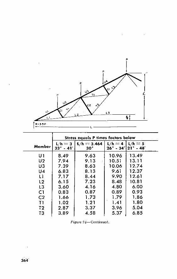
P
C2
L3 L2 y
R-35P
Stress equals P times factors beiow
Member L/h = 3
33° - 41' l/h = 3.464
30° L/h — 4 26° - 34'
L/h = 5 21° - 48'
U1 U2 U3 U4 L1 L2 L3 Cl C2 Tl T2 T3
8.49 7.94 7.39 6.83 7.17 6.15 3.60 0.83 1.66 1.02 2.87 3.89
9.63 9.13 8.63 8.13 8.44 7.23 4.16 0.87 1.73 1.21 3.37 4.58
10.96 10.51 10.06 9.61 9.90 8.48 4.80 0.89 1.79 1.41 3.96 5.37
13.49 13.11 12.74 12.37 12.61 10.81 6.00 0.93 1.86 1.80 5.04 6.85
Figure 74—Continued.
364

P3 P2 P2
Ü2 U 3 U4
T 4 T3
C2 C2
L2 L2 L3
Member TT “P5~ T3T 3 Panel« FT "
LI and L2
L3 and U2
14, U3 and U4
U1
T1
T2
T3
T4
Cl
C2
-s- h
h
h
•Vo3 + ha
(a+b) — h
(a+b) h
Vo3 + h3
h
0
Vb3 + h3
h
0
1.0
0
a -i- h
(a+b) -Î- h
(a+b+c) -s- h
-Va1 + h1
h
0
Vb1 + h1
h
-Vc1 + h1
h
0
1.0
1.0
a -j- h
a -i- h
Va3 + h3
h
0
0
0
a -j- h
(a+b) -j- h
-Va1 + h1
h
0
-Vb» + M h
0
1.0
a + h
Vo1 + M h
0
T1
Cl
C2
1.0
0
0
0
1.0
0
10.
0
1.0
NOTES: For loads pi, p2, etc., the coefficients for the chords and diagonals are the same as given for the loads PI, P2, etc. The coefficients for the verticals for loads pi, p2, etc., are given in the supplementary table below the general table.
Figure 7U—Continued.
365

Table l/t8. Moments, Shears, Pier Reactions for Cooper's E-4-5 Loading
Span (feet)
10 11 12 13 14 15 10 17 18 19 20 21 22 23 24 25 20 27 28 29 30 31 32 33 34 35 30 37 38 39 40 42 44 40 48 50 55 GO 05 70 75 80 85 90 95
100 105 110
Maximum moment
(Af) (kips- foot)
G3. 4 73. 0 90. 0
100. 9 123. 8 140. 7 157. 5 174. 4 191. 3 210. 0 233. 0 254. 3 270. 4 298.-0 320. 9 343. 2 305. 4. 387. 7 411. 2 430. 5 401. 7 487. 0 512. 4 537. 7 503. 2 588. 4 017. 2
' 040.1 075. 0 705. 0 737. 2 802. 8 808. 1 933. 0 998. 0
• 1, 009. 7 1, 250. 5 1, 402. 1 1, 084. 7 1, 921. 0 2, 100. 0 2, 432. 5 2, 707. 7 3, 004. -3 3, 300. 9 3, 022. 4 3, 979. 8 4, 372. 7
Maximum shear {V)
End (kips)
33. 8 30. 8 39. 4 41. 0 43. 4 45. 0 57. 8 50. 3 52. 5 54. 5 50. 3 57. 8 59. 3 Ô0. 7 02. 4 03. 9 05. 3 00. 0 OS. o
09. 2 70. 9 72. 5 73. 9 75. 3 70. 0 77. 9 79. 4 80. 8 82. 3 83. 0 84. 9 87. 8 90. 0 93. 2 95. 7 98. 1
104. 2 110. 3 110. 7 124. 3 132. 4 139. 8 147. 1 154. 4 101. 0 108. 8 175. 0 182. 3
Quarter- point (kips)
22. 5 23. 5 24. 4 25. 1 20. .0 28. 2 29. 0 30. 9
.31. 9 32. 9 33. 8 35. 3 30. 8
-38. 2 39. 4 40. 5 41. 5 42. 5 43. 4 44. 2 45. 0 45. 8 40. 0 47. 3 48. 2 49. 0 49: 0 50. 4 51. 0
' 51. 8 52. 7 54. 2 55. 7 57. 1 58. 0 00. 1 02. 9
„ 07. 7 70. 9 74. 2 77. 1 80. 0 84. 5 88. 0 92. 8 97. 4
101. 4 105. 0
Center (kips)
11. 3 12. 2 13. 1 13. 0 14. 0 14. 9 15. 4 15. 0 15. 7 15. 8 15. 8 10. 3 •10. 9 17. 4 17. 8 18. 2 18. 5 19. 0 19. 3 19. 0 19. 9 20. 4 21. 1 21. 0 22. 1 22. 0 23. 2 23. 0 23. 9 24. 4 24. 8 25. 5 20. l'' 20. 0 27. 2 28. 0 29. 7 31. 4 33. 1 34. 0 30. 4 37. 9 39. 7 41. 3 42. 8 44. 3 45. 0 47: 1
Maximum pier
reaction (R) (kips)
45. 0 49. 1 52. 6 55. 4 58. 7 01. 5 04. 0 00. 2 08. 3 70. 7 73. 7
■70. 4 79. 8 81. 2 83. 2 85. 1 87. 4 90. 1 92. 5 94. 9 97. 1 99. 5
102. 3 105. 0 107. 5 109. 8 112. 0 114. 2 110. 7 119. 1 121...5 120. 2 131. 0 135. 8 140. 4 144. 9 157. 9 172. 4 180. 0 199. 2 211. 7 223, 7 234. 7 245. 9 250. 0 200. 9 276. 8 286. 7
Equivalent uniform load
For maximum moment (pound-
foot)
5, 063 4, 887 5, 004 5, 063 5, 049 5, 004 4, 923 4, 824 4, 725 4, 653 4, 644 4, 590 4, 545 4, 500 4, 446 4, 392 4, 338 4, 375 4, 221 4, 163 4, 104 4, 050 4, 005 3, 951 3, 897
*3, 848 3, 816 3, 780 3, 753 3, 721 3, 690
'3, 630 3, 582 3, 537 3, 483 3, 429 3, 339 3, 249 3, 195 3, 137 3, 087 3, 038 3, 002 2, 966 2, 934 2, 898 2, 894 2, 889
For maximum end shear (pound-
foot)
6, 750 0, 705 6, 561 6, 390 6, 210 6, 003 5, 976 5, 922 5, 841 5, 733 5, 625 5, 613 5, 391 5, 274 5, 198 5, 112 5, 027 4, 932 4, 851 4, 770 4, 730 4, 676 4, 617 4, 563 4, 505 4, 451 4, 410 4, 370 4, 329 4, 288 4, 244 4, 185 4, 122 4, 050 3, 987 3, 924 3, 794 3, 672 3, 591 3, 551 3, 528 3, 497 3, 465 3, 429 3, 402 3, 375 3, 334 3, 312
For maximum
pier reaction (pound-
foot)
4, 500 4, 464 4, 374 4, 266 4, 194 4, 100 4, 001 3, 893 3, 789 3, 726 3, 670 3, 636 3, 582 3, 528 3, 465 3, 402 3, 362 3, 339 3, 303 3, 272 3, 236 3, 213 3, 200 3, 182 3, 159 3, 137 3, 110 3, 087 3, 069 3, 051 3, 038 3, 006 2, 979 2, 952 2, 925 2, 898 2, 876 2, 876 2, 862 2, 844 2, 822 2, 799 2, 703 2, 732 2, 700 2, 669 2, 637 2, 606
366

Table 148. Moments, Shears, Pier Reactions for Cooper’s E—45 Loading—Con.
Span (feet)
115 120 125 150 175 200 250
Maximum moment
(Af) (kips- foot)
4, 775. 6 5, 190. 8 5, 621. 0 7, 945. 1
10, 521. 5 13, 357. 1 19, 791. 5
Maximum shear (V)
End (kips)
188. 9 195. 4 201. 8 233. 3 263. 8 293. 7 362. 4
Quarter- point (kips)
-109. 7 113. 8 127. 8 137. 0 155. 6. 172. 6
■206. 6
Center (kips)
'48. 5 50. 0 51. 8 61. 2 70. 4 79. 2
■95. 7-
Maximum pier
reaction (R) (kips)
296. 1 306. 0 310. 1 366. 0 418. 1 471. 4 579. 6
Equivalent uniform load
For maximum moment
‘(pound- foot)
2, 889 2, 885 2, 880 2, 826 2, 750 2, 669 2, 534
For maximum end shear (pound-
foot)
3, 285 3, 258 3, 231 3, 110 3, 015 2, 939 2, 817
For maximum
pier reaction (pounti-
foot)
2, 574 2, 552 2, 529 2, 439 2, 390 2, 358 2, 318
c. The section modulus may be determined from—
0 lot
s=— ■
where— iS=section modulus required for stringers under one rail and is
measured in inches3. Mtot= total-maximum bending moment in inch-pounds.
/=allowáble bending stress in p.s.i. Table 149 gives values for S for various spans and corresponding values of Mt„,.
Table 149. Section Modulus and Shear
Span (feet)
10.....
i-i
12 13-... 14 15.-. 16 17 18..'.. 19 20 21...1 22 23.. .. 24.-.__ 25— 26— 27 28.. .. 29.... 30—
MTOT (feet K)
202. 1 222. 8 255. 8 290. 0 323. 6 348. 6 393. 5
-428. 4 463. 8 502. 2 576. 0 620. 4 665. 3 712. 9 758. 5 806. 2 855. 1 901. 7 952. 6
1005. 9 1060. 7
SREQ (in S)
90 99
114 129 144 155 175 190 206 223 256 275 295 316 336 358 380 401 423 447 471
Maximum shear (*)
. 80.-7 85. 4 89. 4
' 92. 8- 95. 7
.98. 3 103. 5 1Ö8. 0 112. 1 115. 6 121. 7 124. 9 . 127. 8 13Ó. 1 133. 2 136. 2 138. 9 141. 9 144. 5 146. 5 150. 4
Span (feet)
.37. 38. 39. 40'. 42. 44_- 46. 48. 50. 52. 54. 56. 58. 60. 65. 70. 75. 80. 85. 90. 95.
MTOT (feef K)
1462. 5 1526.. 9 1594. 3 1663.. 2 1805. 1 1947. 2 2097. 8 2240.'4 2400. 1 2566 2744 2923 3106 3305 3815 4352 4938 ' 5545 6167 6856 7544
SREQ (in S)
Maximum shear (K)
650 679 709 739 802 865 932 996
1067 1140 1219 1299 1380 1469 1695 1934 2195 2464 2741 3047 3353
171. 4 174. 4 177. 3 179. 8 186. 1 192. 2 198. 1 203. 7 208. 8 213. 9 220. 1 225. 7 231. 1 236. 8 251. 9 268. 3 285. 9 301. 8 317. 6 333. 1 348. 1
367 - 533506-—GO 24

Table 149. Section Modulus and Shear—Continued
Span (feet)
31_ 32_ 33_ 34_ 35- 36.
MTOT (feet +)
1113. 8 1168. 3 1225. 2 1279. 9 1337. 1 1400. 6
SREQ (in S)
495 519 544 569 594 622
Maximum shear (+)
153. 5 156. 5 .159. 5 162. 3 165. 0 168. 2
Span (feet)
100-
105. HO.
115- 120-
125-
MTOT (feet +)
8283 9095 9975
10886 11817 12813
SREQ (in S)
Maximum shear (+)
3681 4042 4433 4838 5252 5695
362. 9 377. 5 392. 0 406. 9 421. 4 436. 5
Section III. STRUCTURAL STEEL
149. Working Stresses
a. Basic Stresses. For permanent construction, the allowable unit stresses are given in the Manual of the American Institute of Steel Construction. For temporary buildings and for milita^ construction in a theater of operations, the allowable unit stresses in structural steel, rivets, bolts, and welds are as follows (except as modified by b below, and unless modifications are required due to the use of steel of specifications which differ from those in the manual referred to above).
(1) Tension. (а) Structural steel, net section (б) Bolts at root of thread (c) Butt welds, section through throat
Pounds per
square inch
27, 000 20,000 20,000
(2) Compression. Pounds per square inch
(а) Plate girders stiffeners, gross section 27, 000 (б) Columns, axial compression, gross sec-
tion, for values of - not over 140: ’ r
Riveted ends
Pinned ends.
21,300 % (r)2
21,-300-JíQ,
Where 1 = unsupported lengths in inches r=least radius of gyration in
inches
(c) Butt welds, section through throat (crush- ing) 24,000
(3) Bending. Pounds per square Inch
(a) Tension on extreme fibers of rolled sec- tions, plate girders, and built-up mem- bers 27,000
368

Pounds per square inch
(6) Compression on extreme fibers of rolled sections, plate girders, and built-up members :
For j less than 15_-
For ^ values between 15 and 40
27,000
27,000- f (0
Where 7= laterally unsupported length in inches
6 = flange width in inches (c) Butt welds. Stresses due to bending shall not exceed
those prescribed above for tension and compression, re- spectively.
(4) Shear. square inch
(a) Rivets and pins 20, 000 (b) Girder web, gross section 16,500 (c) Turned bolts in reamed holes 16, 500 (d) Unfinished bolts 12, 000 (e) Weld metal, on section through throat of fillet weld
or on faying surface area of plug or slot weld 15, 000 Note. Stress in a fillet weld shall be considered as shear on the
throat, for any direction of the applied stress. Neither filled nor fillet-welded plug or slot welds shall be assigned any values in resist- ance to stress other than shear.
Pounds per square inch s m* \ n • uouoie (o) Bearing. shear
(a) Rivets 40, 000 (b) Turned bolts in reamed or drilled holes. 40, 000 (c) Pins (d) Contact area:
J. Milled stiffeners and other milled surfaces #. Fitted stiffeners
Sinqle shear
32.000 32.000 32.000
30, 000 27, 000
(e) Expansion rollers or rockers (pounds per linear inch) in which d is diameter of roller or rocker in inches 600d
b. Stresses jor Wind Loads. All allowable stresses given in a above are increased 30 percent but not to exceed 27,000 pounds per square inch, for members subject to wind loads, provided the sections thus determined are adequate at normal stresses for all loads except wind, and including impact (if any).
c. Bearing on Masonry. square inch (1) Granite 800 (2) Sandstone and limestone 400 (3) Portland-cement concrete 600 (4) Hard brick in cement mortar 250
369
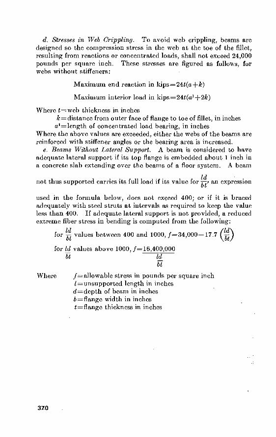
d. Stresses in Web Crippling. To avoid web crippling, beams are designed so the compression stress in the web at the toe of the fillet, resulting from reactions or concentrated loads, shall not exceed 24,000 pounds per square inch. These stresses are figured as follows, for webs without stiffeners:
Where t = web thickness in inches Æ = distance from outer face of flange to toe of fillet, in inches «^length of concentrated load bearing, in inches
Where the above values are exceeded, either the webs of the beams are reinforced with stiffener angles or the bearing area is increased.
e. Beams Without Lateral Support. A beam is considered to have adequate lateral support if its top flange is embedded about 1 inch in a concrete slab extending over the beams of a floor system. A beam
not thus supported carries its full load if its value for an expression
used in the formula below, does not exceed 400; or if it is braced adequately with steel struts at intervals as required to keep the value less than 400. If adequate lateral support is not provided, a reduced extreme fiber stress in bending is computed from the following:
Maximum end reaction in kips=24£(a + &)
Maximum interior load in kips = 24i(a1-{-2&)
for ^ values between 400 and 1000, /=34,000—17.7
for Id values above 1000, /= 16,400,000 bt ld_
bt
Where /= allowable stress in pounds per square inch Z=unsupported length in inches d=depth of beam in inches ¿>=flange width in inches i = flange thickness in inches
370

150. Weights and Areas of Bars and Plates Table 150. . Weights and Aieas of Bars and Plates
Size or thickness (inches)
Square ami round bars
Weight (pounds per foot)
Square Round
Area (square inches)
Square
Plates ] foot wide
Weight (pounds per foot)
Area (square inches)
3/s H
% % 1
itf 1/4 VA 2
3 '¿'A—- - ■i
Size or thickness
(millimeters) (inches)
0_ - 6_ _
7.. 8.. 10.
12.
14. 16. 18. 20.
22.
24. 26. 28^ 30. 32. 34. 36. 38. 40. 45. 50-
0. 20 . 24 . 28 . 32 . 39 . 47
. . 55 . 63 . 71 . 79 . 87 594
1. 02 1. 10 1. 18 1. 26 1. 34 1. 42 1. 50 1. 57 1. 77 1..97
0. 213 . 478 . 850
. 1. 328 1. 913 2. -603 3. 400 4. 303 5. 313 7. 650
13. 600- 21. 250 30. 600 4i: 65 54. 40
0. 167 . 376 . 668
1. 403 1. 502 2. 044 2. '670 3. 380 4. 172 6. 008
10. 681 16. 690 24. 033 32. 71 42.-73
. 136
. 204
. 272
. 340
. 544
. 748 1. 020 1. 258 ' 1. 700 2. 108 2. 550 3! 026 3. 570 4. 148 4. 760 5. 406 6. 086 6. 834 7. 616 8. 432
10. 676 13. 192
. 103
. 149
. 203
. 265
. 415.
. 597
. 813 Í.-062 1. 344 1. 660 2. 003 2. 386 2. 802 3. 246 3. 730 4. 240 4. 791 5. 369 5. 981 6. 633 8. 400
10. 349
0. 0625 . 1406 . 2500
' .3906 . 5625 . 7656
1. 0000 1. 2656 1. 5625 2. 2500 4. 00 6. 25 9,00
12. 25 16..00
.04
. 06
. 08
. 10
. 16 22
. 30
. 37
. 50
. 62
. 75
. 89 1. 05 1. 22 1. 40 1. 59 1. 79 2. 01 2. 24 2. 48 3. 14 3. 88
0. 0491 . 1105 . 1963 . 3068 . 4418 . 6013 . 7854 . 9940
1. 2272 1. 7671 3. 1416 4. 9087 7. 0686 9. 621
12. 566
. 03
. 05
. 06
. 08
. 12
. 17
. 24
. 31
. 40
. 49
. 59
. 69
. 82
. 95 1. 09 1. 25 1. 41 1. 58 1. 77 1. 94 2. 46
■3. 05
10. 20 15. 30 20. 40 25. 50 30. 60 35. 70 40. 80 45. 90 51. 00 61. 20 81. 60
102. 00 122. 40 142. 80 163. 20
7. 990 9. 622
11. 254 12. 852 16. 082 19. 244 22. 474 25. 704 28. 934
-32.-096 35. 326 38. .556 42. 602 44. 948 48. 178 51. 408 54. 638 57. 800 61. 030 64. 260 72. 284 80. 342
3. 00 4. 50 6. 00 7. 50 9. 00
10. 50 12. 00 13. 50 15. 00 18. 00 24. 00 30. 00 36. 00 42. 00 48. 00
2. 35 2. 83 3. 31 3. 78 4. 73 5. 66 6. 61 7. 56 8. 51 9. 44
10. 39 11. 34 12. 53 13. 22 14. 17 15. 12 16. 07 17. 00
■ 1-7: 95 18. 90 21. 26 23:- 63
(Reprinted from “Steel Construction“ by permission of American Institute of Steel Construction. Copyright 1947.)
371

372
151. Dimensions and Properties of U.S. Sections
Tables 151 to 154 inclusive are reprinted from “Steel Construction” by permission of the Ameri- can Institute of Steel Construction (copyright 1947). The WF and angle tables arc abridged listings.
a. WF Shapes.
Table 151. WF Shapes
■—x
Nominal size
In.
36 X 16)4- 36 x 12... 33 x 11H- 30 x 15 30 x 10'A- 27 x10..- 24 x12__- 24x9 21 x 8}C„ 18 x 7J4 16 x 7 14 x 6% 12x12-.-
Welght per foot
Lb
230 150 130 172 108 94
100 76 62 50 36 30 65
Area
In.
67. 73 44. 16 38. 26 50. 65 31. 77 27. 65 29. 43 22. 37 18. 23 14. 71 10. 59 8. 81
19. 11
Depth
In.
35. 88 35. 84 33. 10 29. 88 29. 82 26. 91 24. 00 23. 91 20. 99 18. 00 15. 85 13. 80 12. 12
Flange
Width
In.
16. 475 I 1. 972 I l. 510 14. 985 10. 484
9. 990 12. 000 8. 985 8. 240 7. 500 6. 992 6. 733
12. 000
Thickness
In.
1. 260 . 940 . 855
1. 065 . 760 . 747 . 775 . 682 . 615 . 570 . 428 . 383 . 606
Well thick- ness
In.
765 625 580 655 548 490 468 440 400 358 299 270 390
Axis X-X
In.
14988. 4 9012. 1 6699. 0 7891. 5 4461. 0 3266. 7 2987. 3 2096. 4 1326. 8 800. 6 446. 3 289. 6 533. 4
s
In.
835. 5 502. 9 404. 8 528. 2 299. 2 242. 8 248. 9 175. 4 126. 4
89. 0 56. 3 41. 8 88. 0
In.
14. 88 14. 29 13. 23 12. 48 11. 85 10. 87 10. 08
9. 68 8. 53 7. 38 6. 49 5. 73 5. 28
Axis Y-Y Gage
In.
870. 9 250. 4 201. 4 550. 1 135. 1 115. 1 203. 5
76. 5 53. 1 37. 2 22. 1 17. 5
174. 6
105. 7 41. 8 35. 0 73. 4 25. 8 23. 0 33. 9 17. 0 12. 9
9. 9 6. 3 5. 2
29. 1
In.
3. 59 2. 38 2. 29 3. 30 2. 06 2. 04 2. 63 1.85 1. 71 1. 59 1. 45 1. 41 3. 02
In.
5)4 5'A 5/2 5/2
5/ 5/ 5/ 5/ 5/ 3/ 3/ 3/
5K

373
12 x 6H ioxio...; 10 x 5% 8x8
8x6/2 8x5/ 6x6 4x4
27 49 21 31 24 17 25 13
7. 97 14. 40
6. 19 9. 12 7. 06 5..00 7. 37 3. 82
11. 95 10. 00
9. 90 8. 00 7. 93 8. 00 63. 7 4. 16
6. 500 10. 000
5. 750 8. 000 6. 500 5. 250 8. 080 4. 060
. 400
. 558
. 340
. 433
. 398
. 308
. 456
. 345
. 240
. 340
. 240 . 288 . 245 . 230 . 320 . 280
204. 1 272. 9 106. 3 109. 7 82. 5 56. 4 53. 5 11. 3
34. 1 54. 6 21. 5 27. 4 20. 8 14. 1 16. 8 5. 45
5. 06 4. 35 4. 14 3. 47 3. 42 3. 36 2. 69 1. 72
16. 6 93. 0
9. 7 37. 0 18. 2
6. 7 17. 1 3. 76
5. 1 18. 6 3. 4 9. 2 5. 6 2. 6 5. 6
1. 85
1. 44 2. 54 1. 25 2. 01 1. 61 1. 16 1. 52
. 99
3/
5/2 2% 5/2
3/2
2% 3/
2/
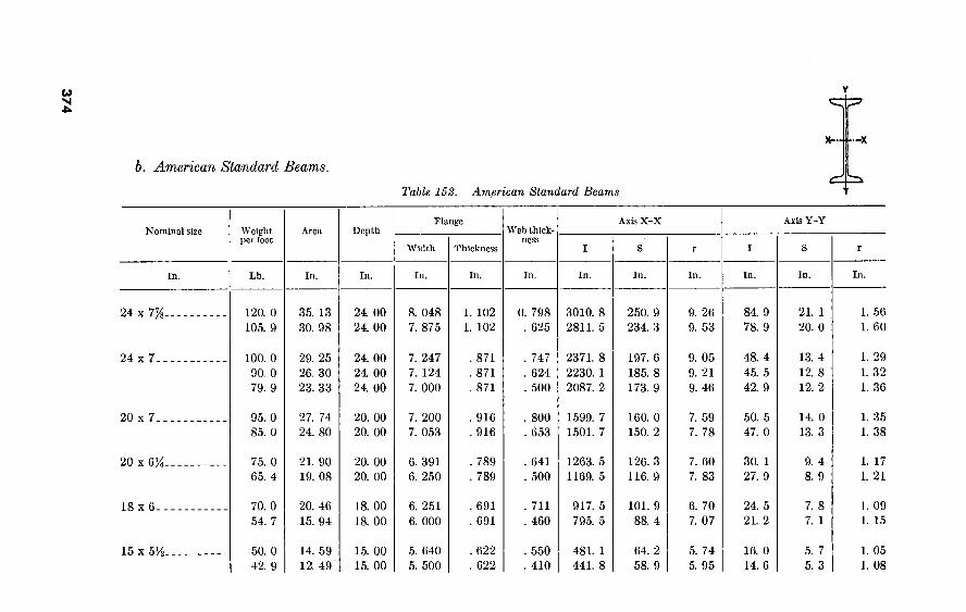
37
4
b. American Standard Beams.
Table 152. American Standard Beams
X- ■—X
4=
Nominal size Weight per foot
Area Depth Flange
Thickness
Web thick- ness
Axis X-X Axis Y-Y
In.
24 x 7%.
24 x 7.
20 x 7.
20 x VA-
IS x 6-
15 x 5H-
Lb.
120. 0 105. 9
100. 0 90. 0 79. 9
95. 0 85. 0
75. 0 65. 4
70. 0 54. 7
50. 0 42. 9
In. In. In. In. In. In. In. In. In.
35. 13 30. 98
29. 25 26. 30 23. 33
27. 74 24. 80
21. 90 19. 08
20. 46 15. 94
14. 59 12. 49
24. 00 24. 00
24. 00 24. 00 24. 00
20. 00 20. 00
20. 00 20. 00
18. 00 18. 00
15. 00 15. 00
8. 048 7. 875
7. 247 7. 124 7. 000
7. 200 7. 053
6. 391 6. 250
6. 251 6. 000
5. 640 5. 500
1. 102 1. 102
. 871
. 871
. 871
. 916
. 916
. 789
. 789
. 691
. 691
. 622
. 622
0. 798 . 625
. 747
. 624 . 500
. 800 . 653
. 641
. 500
. 711
. 460
. 550
. 410
3010. 8 2811. 5
2371. 8 2230. 1 2087. 2
1599. 7 1501. 7
1263. 5 1169. 5
917. 5 795. 5
481. 1 441. 8
250. 9 234. 3
197. 6 185. 8 173. 9
160. 0 150. 2
126. 3 116. 9
101. 9 88. 4
64. 2 58. 9
9. 26 9. 53
9. 05 9. 21 9. 46
7. 59 7. 78
7. 60 7. 83
6. 70 7. 07
5. 74 5. 95
84. 9 78. 9
48. 4 45. 5 42. 9
50. 5 47. 0
30. 1 27. 9
24. 5 21. 2
16. 0 14. 6
In.
21. 1 20. 0
13. 4 12. 8 12. 2
14. 0 13. 3
9. 4 8. 9
7. 8 7. 1
5. 7 5. 3
In.
1. 56 1. 60
1. 29 1. 32 1. 36
1. 35 1. 38
1. 17 1. 21
1. 09 I. 15
1. 05 1. 08

12 x 5]4.
12x5
10 x 4%
8 x 4
7 x35t
6 x 35t ,
5 x 3
4 x 25t
3 x 25t-:
50. 0 40. 8
35. 0 31. 8
35. 0 25. 4
23. 0 18. 4
20. 0 15. 3
17. 25 •'12. 5
14. 75 10. 0
9. 5 7. 7
7. 5 5. 7
14. 57 11. 84
10. 20 9. 26
10. 22 7. 38
6. 71 5, 34
5. 83 4. 43
5. 02 3. 61
4. 29 2. 87
2. 76 2. 21
2. 17 1. 64
12. 00 •12. 00
12. 00 12. 00
10. 00 10. 00
8. 00 8. Ó0
7. 00 7. 00
• 6. 00’
6. 00
. 5. 00 5. 00
4. 00 4. 00
3. 00 3. 00
Ci ,-N Ln
5. 477 5. 250
5.. 078 5. 000
4. 944 4. 660
4. 171 4. 000
3. 860 3. 660
3. 565 3. 330
3. 284 3. 000
2. 796 2. 660
2. 509 ' 2. 330
. 659 • :. 659
. 544
. 544
. 491
..491
. 425
. 425
. 392
. 392
. 359
. 359
. 326
. 326
. 293
. 293
. 260
. 260
. 687 . 460
: 428 ‘ . 350
. 594
. 310
. 441
. 270
. 450
. 250
. 465
. 230
. 494
. 210
. 326
. 190
. 349
. 170
301. 6 268. 9
227. 0 215. 8
145. 8 122. 1
64. 2 56. 9
41. 9 36. 2
26. 0 21. 8
15. 0 12. 1
6. 7 6. 0
.2. 9 2. 5
50. 3 44. 8
37. 8 36. 0
29. 2 24. 4
16. 0 14. 2
12. 0 10. 4
8. 7 7. 3
6. 0
4. 8
3. 3' 3. 0
1. 9 1. 7
4. 55 4. 77
4. 72 4. 83
3. 78 4. 07
3. 09 3. 26
2. 68 2. 86
2. 28 2. 46
1. 87 .2. 05
1. 56 1. 64
1. 15 1. 23
16. 0 13. 8
10. 0 9. 5
8. 5 6. 9
4. 4 3. 8
3. 1 2. 7
2. 3 1. 8
1. 7 1. 2
. 91
. 77
. 59
. 46
5. 8 5. 3
3. 9 3. 8'
3. 4 3. 0
2. 1 1. 9
1. 6 1. 5
1. 3 1. 1
1. 0 . 82
. 65
. 58
. 47
. 40
1. 05 1. 08
. 99 1. 01
. 91
. 97
. 81
. 84
. 74
. 78
. 68
. 72
. 63
. 65
. 58
. 59
. 52
. 53

376
—X
c. American Standard Channels.
Table 153. American Standard Channels
Nominal size
In.
Weight per foot
Lb.
Area
In.
Depth
In.
Flange
Width
In.
Average thickness
In.
Web Thick ness
Axis X-X Axis Y-Y
In. In. In. In. In. In. In.
18 X 4 i.
15 x
12 x 3.
58. 0 51. 9 45. 8 42. 7
50. 0 40. 0 33. 9
30. 0 25. 0 20. 7
16. 98 15. 18 13. 38 12. 48
14. 64 11. 70
9. 90
8. 79 7. 32 6. 03
18. 00 ]& 00 18. 00 18. 00
15. 00 15. 00 15. 00.
12. 00 12. 00 12. 00
4. 200 4. 100 4. 000 3. 950
3. 716 3. 520 3. 400
3. 170 3. 047 2. 940
0. 625 . 625 . 625 . 625
. 650
. 650
. 650
. 501
. 501
. 501
0. 700 . 600 . 500
.. 450
. 716
. 520
. 400
. 510
. 387
. 280
670. 7 622. 1 573. 5 549. 2
401. 4 346. 3 312. 6
161. 2 143. 5 128. 1
74. 5 69. 1 63. 7 61. 0
53. 6 46. 2 41. 7
26. 9 23. 9 21. 4
6. 29 6. 40 6. 55 6. 64
5. 24 5. 44 5. 62
4. 28 4. 43 4. 61
18. 5 17. 1 15. 8 15. 0
11. 2 9. 3 8. 2
5. 2 4. 5 3. 9
5. 6 5. 3 5. 1 4. 9
3. 8 3. 4 3. 2
2. 1 1. 9 1. 7
1. 04 1.06 1. 09 1. 10
. 87
. 89
. 91
. 77
. 79
. 81
0. 88 . 87 . 8?
. 90
. 80
. 78
. 79
.. 68 '. 68 . 70

377
10 x 2%.
9x2'A-
8x2%.
7 x 2%.
6x2.
5 x 1%.
4 x 1%.
3 x VA-
SO. 0 25. 0 20. 0 15. 3
20. 0 15. 0 13. 4
18. 75 13. 75 11. 5
14. 75 12. 25
9. 8
13. 0 10. 5
8. 2
9. 0 6. 7
7. 25 5. 4
6. 0 5. 0 4. 1
8. 80 7. 33 5. 86 4 47
5. 86 4. 39 3. 89
5. 49 4. 02 3. 36
4. 32 3. 58 2. 85
3. 81 3. 07 2. 39
2. 63 1. 95
2. 12 1. 56
1. 75 1. 46 1. 19
10. 00 10. 00 10. 00 10. 00
9. 00 9. 00 9. 00
8. 00 8. 00 8. 00
7. 00 7. 00 7. 00
6. 00 6. 00 6. 00
5. 00 5. 00
4. 00 4. 00
3. 00 3. 00 3. 00
3. 033 2. 886
2. 739 2. 600
2. 648 2. 485 2. 430
2. 527 2. 343 2. 260
2. 299 2. 194 2. 090
2. 157 2. 034 1. 920
1. 885 1. 750
1. 720 1. 580
1. 596 1. 498 1. 410
436 436 436 436
. 413
. 413
. 413
. 390
. 390
. 390
. 366
. 366
. 366
. 343
. 343
. 343
. 320
. 320
. 296 . 296
. 273
. 273
. 273
673 526 379 240
448 285
. 230
. 487
. 303
. 220
. 419
. 314
. 210
. 437
. 314
. 200
. 325 . 190
. 320
. 180
. 356
. 258
. 170
103. 0 90. 7 78. 5 66. 9
60. 6 50. 7 47. 3
43. 7 35. 8 32. 3
27. 1 24. 1 21. 1
17. 3 15. 1 13. 0
8. 8 7. 4
4. 5 3. 8
2. 1 1. 8 1. 6
20. 6
18. 1 15. 7 13. 4
13. 5 11. 3 10. 5
10. 9 9. 0 8. 1
7. 7 6. 9 6. 0
5. 8 5. 0 4. 3
3. 5 3. 0
2. 3 1. 9
1. 4 1. 2 1. 1
3. 42 3. 52 3. 66 3. 87
3. 22 3. 40 3. 49
2. 82 2. 99 3. 10
2. 51 2. 59 2. 72
2. 13 2. 22 2. 34
1. 83 1. 95
1. 47 1. 56
1. 08 1. 12 1. 17
4. 0 3. 4 2. 8 2. 3
2. 4 1. 9 1. 8
2. 0 1. 5 1. 3
1. 4 1. 2
. 98
1. 1 . 87 . 70
. 64
. 48
. 44 . 32
. 31
. 25
. 20
1. 7 1. 5 1. 3 1. 2
1. 2 1. 0
. 97
1. 0 . 86 . 79
. 79
. 71
. 63
. 65
. 57
. 50
. 45
. 38
. 35
. 29
. 27
. 24
. 21
67 68 70 72.
65 67 67
, 60 . 62 , 63
. 57
. 58 , 59
, 53 53
. 54
. 49
. 50
. 46
. 45
. 42
. 41
. 41
1 Car and Shipbuilding Channel, not an American Standard.
. 65
. 62
. 61
. 64
. 59
. 59
. 61
. 57
. 56
. 58
. 53
. 53
. 55
. 52
. 50
. 52
. 48
. 49
. 46
• 46
. 46
. 44
. 44

d. Selected Angles.
Table 154- Selected Angles
1 i
' Z
Size
8x8-..
6x6 5x5 4x4_..
3M x 3K- 3x3--. 2x2 8x6 6x4
5 x 3K--
5x3---
4 x 3-_.
3Hx 3--
Thick- ness
% Me % M M
Weight perft.4b.
51. 0 33. 1 23. 6 12. 8
9. 8 8. 2 7. 2 6. 1 3. 19
33. 8 16. 2 12. 3 10. 4 8. 7 9. 8 8. 2 8. 5 7. 2 6. 6
Area (sq. in.)
15. 00 9. 73 6. 94 3. 75 2. 86 2. 40 2. 09 1. 78
. 94 9. 94 4. 75 3. 61 3. 05 2. 56 2. 86 2. 40 2. 48 2. 09 1. 93
Axis X-X
Inches 89. 0 31. 9 15. 7
5. 6 4. 4 3. 7 2. 5 1. 5
. 35 63. 4 17. 4 13. 5
I- 7.-8.- 6. 6 7. 4 6. 3 4. 0 3. 4 2. 3
Inches 15. 8
7. 6 4. 5 2. 0 1. 5 1. 3
. 98
. 71
. 25 11. 7
4. 3 3. 3
4-2-3 1. 9 2. 2 1. 9 1. 5 1. 2
. 95
Inches 2. 44 1. 81 1. 51 1. 22 1. 23 1. 24 1. 08
. 92
. 61 2. 53 1. 91 1. 93 1. 60 1..61 1. 61 1. 61 1. 26 1. 27 1. 10
Axis Y-Y
Inches
s A M E
30. 7 6. 3 4. 9 3. 2 2. 7 2. 0 1. 8 1. 9 1. 7 1. 6
Inches
A S
6. 9 2. 1 1. 6 1. 2 1. 0
. 89
. 75
. 87
. 73
. 72
Inches
A X I S
X-X
1. 76 1. 15 1. 17 1. 02 1. 03
. 84
. 85
. 88
. 89
. 90
Axis Z-Z
Inches 1. 56 1. 17
. 97
. 78
. 79
. 79
. 69
. 59
. 39 1. 29
. 87
. 88
. 76
. 76
. 65
. 66
. 64
. 65
. 63
(Reprinted from Steel Construction by permission of American Institute of Steel Construction. Copy- right 1947.)
e. Steel Rails. Under the policies of the Department of Defense, U.S. made steel rails approved for use by the Corps of Engineers are confined to the following types: For ordinary use, 85-pound A.S.C.E. minimum; as an alternative, if economically justified, 90-pound A.R.A.-A.; for heavier duty (on main lines and access or other tracks where the movement may be classified as “heavy” or where the desired speed exceeds 40 miles per hour), 115-pound A.R.E.A. sections. All such rails must conform to military specifications. Figure 75 shows cross sections of A.S.C.E. rails and of A.R.A. and A.R.E.A. rails and their characteristics.
378

Sir? > —„
' A. S. C. E.
A. R. A.
A. R. E. A
Type
A.S.C.E.
A.S. C.E.
A.S .C E.
85
90
115
DIMENSIONS IN INCHES
16
Slope in
(Degr's]
13
Top
21 16
2 — 32
2— ¿32
9 2ië
2— c32
12
10
9
Î6
9
Te I3: 32
12
14
Gage
g
17 2 64
64
PROPERTIES
Gross Area
8.33
8.82
II. 25
On Honz. Axis
30.1
387
656
2.47 11. I
12 6
180
2,54
238
■ Figure-75. Dimensions and properties of currently produced steel rails.
379-

38
0
j. Steel Pipe. Table Í-55. Steel Pipe
Nominal diameter (inches)
Dimensions
Outside diameter (inches)
Inside diameter (inches)
Thick- ness
(inches)
Weight per foot-pound
Plain ends
Thread <fc cplg.
Threads per
inch
Couplings
Outside diameter (inches)
Length (inch-
es)
Weight (pounds)
Properties
I (inches)
A (Inches) (Inches)
STANDARD
y*. %- H-
%- i„.
itf-
iH- 2...
2/2-
3—
3H- 4—
5.. .
6.. .
8...
8...
10...
10...
10...
12...
12...
0. 405 . 540 . 675 . 840
1. 050 1. 315 1. 600 1. 900 2. 375 2. 875 3. 500 4. 000 4. 500 5. 563 6. 625 8. 625 8. 625
10. 750 10. 750 10. 750 12. 750 12. 750
0. 269 . 364 . 493 . 622 . 824
1. 049 1. 380 1. 610 2. 067 2. 469 3. 068 3. 548 4. 026 5. 047 6. 065 8. 071 7. 981
10. 192 10. 136 10. 020 12. 090 12. 000
0. 068 . 088 . 091 . 109 . 113 . 133 . 140 . 145 . 154 . 203 . 216 . 226 . 237 . 258 . 280 . 277 . 322 . 279 . 307 . 365 . 330 . 375
0. 24 . 42 . 57 . 85
1. 13 1. 68 2. 27 2. 72 3. 65 5. 79 7. 58 9. 11
10. 79 14. 62 18. 97 24. 70 28. 55 31. 20 34. 24 40. 48 43. 77 49. 56
0. 25 . 43 . 57 .85
1.13 1. '68 2.28 2. 73 3. 68 5. 82 7.'62 9. 20
10. 89 14.'81 19.19 25. '00 28.‘81 32. 00 35. 00 41. 13 45. 00 50. 71
27 18 18 14 14 ny, ny ivy ny
8 8 8 8 8 8 8 8 8 8 8 8 8
0. 562 . 685 . 848
1. 024 l. 281 1. 576 1. 950 2. 218 2. 760 3. 276 3. 948 4. 591 5. 091 6. 296 7. 358 9. 420 9. 420
11. 721 11. 721 11. 721 13. 958 13. 958
% 1
1%
l3/8
IX IX 2X 2% 2% 2% 3y8
3% 3% 4/s
4% 6'A 6'A 6/8 6/s 6H
0. 03 . 04 . 07 . 12 . 21 .35 . 55 . 76
1. 23 1. 76 2. 55 4. '33 5. 41 9. 16
10. 82 15. 84 15. 84 33. 92 33. 92 33. 92 48. 27 48. 27
0. 001 . 003 . 007 . 017 .037 . 087 . 195 . 310 . 666
1. 530 3. 017
, 4. 788 7. 233
15. 16 28. 14 63. 35 72. 49
125. 9 137. 4 160. 7 .
'248. 5 279. 3
0. 072 . 125 . 167 . 250 . 333 . 494 . 669 . 799
1. 075 1. 704 2. 228 2. 680 3. 174
' 4. 300 5. 581
•7. 265 8. 399 9. 178
10. 07 11. 91 12. 88 14. 58
0. 12 . 16 . 21 . 26 . 33 . 42 . 54 . 62 . 79 . 95
1. 16 1. 34 1. 51 1. 88 2. 25 2. 95 2. 94 3. 70 3. 69 3. 67 4. 39 4. 38

381 EXTRA STRONG
y8- ji- y8- 'A- %-
1.. .
iX- 1A- 2.. .
■2X2-
3—
3X2-
4.. . 5.. . 6.. .
8— 10...
12...
0. 405 .540 . 675 . 840
1. 050 1. 315 1. 660 1. 900 2. 375 2. 875, 3. 500 4. 000 4. 500 5. 563 6. 625 8. 625
10. 750 12. 750
0. 215 . 302 . 423 . 546 . 742 . 957
1. 278 1. 500 1. 939 2. 323 2. 900 3. 364 3. 826 4. 813 5. 761 7. 625 9. 750
11. 750
0. 095 . 119 . 126 . 147 . 154 . 179 . 191 . 200 . 218 . 276 . 300 . 318 . 337 . 375 . 432 . 500 . 500 . 500
0. 31 . 54 . 74
1. 09 1. 47 2. 17 3. 00 3. 63 5. 02 7. 66
10. 25 12. 51 14. 98 20. 78 28. 57 43. 39 54. 74 65. 42
0. 32 . 54 . 75
1.10 1. 49 2. 20
3. 05 3. 69 5. 13 7. 83
10. 46 12. 82 15. 39 21. 42 29. 33 44. 72 56. 94 68. 02
27 18 18 14 14 ny IVA
ny iiy. 8 ' 8 8 8 8 8 8 8 8
0. 582 . 724 . 898
1. 085 I. 316 1. 575 2. 054 2. 294 2. 870 3. 389 4. 014 4. 628 5. 233 6. 420 7. 482 9. 596
11. 958 13. 958
l/s m ir* i« 2/8 2/8
2/8
2/s 3/8
4/8
4/8
4/8 4/s 5/8 5/ 6/k
6/s
6/s
0. 05 . 07 . 13 . 22
. 33
. 47 1. 04 1. 17 2. 17 3. 43 4. 13 6. 29 8. 16
12. 87 15. 18 26. 63 44. 16 51. 99
0. 001 . 004 . 009 . 020 . 045 . 106 . 242 . 391 . 868
1. 924 3. 894 6. 280 9. 610
20. 67 40. 49
105. 7 211. 9 361. 5
0. 093 . 157 . 217 . 320 . 433 . 639 . 881
1. 068 1. 477 2. 254 3. 016 3. 678 4. 407 6. 112
8. 405 12. 76 16. 10 19. 24
0. IT . 15 . 20
. 25
. 32
. 41
. 52
. 61'
. 77
. 92 1. 14 1. 31 1. 48 1. 84 2. 20 2. 88 3. 53 4. 34

382
Table 155. Steel Pipe—Continued
Dimensions
Nominal diameter (inches)
Outside diameter (inches)
Inside diameter (inches)
Thick- ness
(inches)
Weight per foot-pound
Plain ends
Thread & cplgj
Threads per inch
Couplings
Outside diameter (Inches)
Length (inch-
es)
. Weight (pounds)
Properties
I (inches)
A (inches) (Inches)
DOUBLE—EXTRA STRONG
Y*- i-_.
DÍ- 1/2-
2__.
2JÍ- 3— 3)4- 4„. 5— 6„.
8—
0. 840 1. 050 1. 315 1. 660 1. 900 2. 375 2. 875 3. 500 4. 000 4. 500 5. 563 6. 625 8. 625
0. 252 . 434 . 599 . 896
1. 100 1. 503 1. 771 2. 300 2. 728 3. 152 4. 063 4. 897 6. 875
0. 294 . 308 . 358 . 382 . 400 . 436 . 552 . 600 . 636 . 674 . 750 . 864 . 875
1. 71 2. 44 3. 66 5. 21 6. 41 9. 03
13. 70 18. 58 22. 85 27. 54 38. 55 53. 16 72. 42
1. 73 2. 46 3. 68 5. 27 6. 47 9. 14
13. S1! 18. 7Ö 23. lb 27. 95 39. 20 53. 92 73. 76
14 14
11/ 11/ 11/ 11/ 8 8 8 8 8 8 8
1. 085 1. 316 1. 575 2. 054 2. 294 2. 870 3. 389 4. 014 4. 628 5. 233 6. 420 7. 482 9. 596
1/ 2/ 2% 2% 2% 3% 4/ 4/ 4/ 4/ 5/ 5/ 6/
0. 22 . 33 . 47
1. 04 1. 17 2. 17 3. 43 4. 13 6. 29 8. 16
12. 87 15. 18 26. 63
0. 024 . 058 .140 . 341 . 568
1. 311 2. 871 5. 992 9. 848
15. 28 33. 64 66. 33
162. 0
0. 504 . 718
1. 076 1. 534 1. 885 2. 656 4. 028 5. 466 6. 721 8. 101
11. 34 15. 64 21. 30
0. 22 . 28 . 36 . 47 . 55 . 70 . 84
1. 05 1. 21 1. 37 1. 72 2. 06 2. 76

533506
LAHQE O.D. PIPE
Pipe 14" and larger is sold by actual O.S. diameter and thickness. Sizes, 14", 15", and 16" are available regularly in thicknesses varying by J'io" from '/" to 1", inclusive. All pipe is furnished random length unless otherwise ordered, viz: 12 to 22 feet with privilege of furnishing 5 percent in 6 to 12foot
lengths. Pipe railing is most economically detailed with slip joints and random lengths between couplings. C5 O
U CO GJ

CO 00 ■U
Y
152. Dimensions and Properties oí Australian Beams
Table 156. Australian Beams
Ref. No. ASB- Size
Weight per foot
Area Depth
Flange
Width Thick- ness
Web thick- ness
Axis X-X Axis Y-Y
!..
2..
3.. 4.. 5.. 6..
7- . 8- .
EL- 10.
11.
12.
13. 14. 15. 16. 17. 18.
Inches
3 x LH 4 x 3
4H x 2 6x3
6x5 7x 3K 8x4 8x6 9x4
10 x 4/2 10 x 6
.10 x 8 12 x 5 12 x 8 13 x 5 14 x 5/2
15 x 6 16 x 6
Pounds
4. 0 10.0 7.0
12.0 25. 0 15. 0 18. 0 35. 0 21. 0
25. 0 40. 0 55. 0 30. 0 65. 0 35. 0 40. 0 45. 0 50. 0
Inches
1. 18 2. 94 2. 06 3. 53 7. 35 4. 42 5. 30
10. 30 6. 18 7. 35
11. 77 16. 18
8. 83 19. 12 10. 30 11. 77 13. 24 14. 71
Inches
3 4 4% 6 6 7 8 8 9
10 10 10 12 12
13 14 15 16
Inches
VA 3 2 3 5
3H 4 6 4 4A 6 8 5 8 5 5A 6
6
Inches
0. 249 . 347 . 322 . 377 . 561 . 398 . 398 . 648 . 457 . 505 . 709 . 783 . 507
.. 904
.. 604 . 627 . 655 . 726
Inches
0. 16 . 24 . 19 . 23 . 33 . 25 . 28 . 35 . 30 . 30 . 36 . 40 . 33 . 43 . 35 . 37 . 38 . 40
Inches
1.7
7. 8 6. 7
21. 0
45. 2 35. 9 55. 6
115. 1 81. 1
122. 3 204. 8 288. 7 206. 9 487. 8 283. 5 377. 1 491. 9 618. 1
Inches
1. 1 3. 9 3. 0 7. 0
15. 1 10. 3 13. 9 28. 8 18. 0 24. 5 41. 0 57. 7 34. 5 81. 3 43. 6 53. 9 65. 6 77. 3
Inches ■
1. 19 1. 63 1. 80 2. 44 2. 48 2. 85 3. 24 3. 34 3. 62 4. 08 4. 17 4. 22 4. 84 5. 05 5. 25 5. 66 6. 09 6. 48
Inches
0. 13 1. 32
. 38 1. 46 9. 87 2. 41 3. 51
19. 54 4. 15 6. 49
21. 76 54. 74
8. 77 65. 18 10. 82 14. 79 19. 87 22. 47
Inches
0. 17 . 88 . 38 . 97
3. 95 1. 38 1. 75 6. 51 2. 07 2. 88 7. 25
13. 69 3. 51
16. 30 4. 33 5. 38 6. 62 7. 49
Inches
0. 33 . ö) . 43 . 64
1. 16 . 74 . 8Í
1. 38 . 82 . 94
1. 36 1. 84 1. 00 1. 85 1. 03 1. 12 1. 23 1. 24

385
19. 20.
21.
22.
23.
16 x 8 18 x 6 20 x GH 22 x 7 24 x 7/
75. 0 55. 0 65. 0 75. 0
100. 0
22. 06 16. 18 19. 12 22. 06 29. 39
16 18 20
22 24
8 6 6/2
7 7/
. 938
. 757
. 820
. 834 1. 070
48 42
, 45 50
. 60
973. 9 841. 8
1226. 2 1676. 8 2654. 8
121. 7 93. 5
122. 6 152. 4 221. 2
6. 64 7. 21 8. 01 8. 72 9. 50
68. 30 23. 64 32. 56 41. 07 66. 87
17. 08 7. 88
10. 02 11. 73 17. 83
1. 76 1. 21 1. 31 1. 36 1. 51

386
Y
X— —X
153. Dimensions and Properties of Austrian and Danish Beams
Table 157. Austrian and Danish Beams
Number of profile
8_
9. 10.
11.
12.
13. 14. 15. 16. 17. 18. 19. 20.
21.
22.
23. 24.
Depth in milli-
meters
Milli- meters
80 90
100 110
120 130 140 150 160 170 180 190 200
210 220 230 240
Weight per foot
Pounds
4. 0 4. 8 5. 6 6. 5 7. 5 8. 5 9. 7
10. 8 12. 0
13. 3 14. 7 16. 1 17. 7 19. 2 20. 9 22. 5 24. 3
Inches
1. 17 1. 40 1. 64 1. 91 2. 20 2. 50 2. 84 3. 10 3. 53 3. 91 4. 32 4. 73 5. 19 5. 63 6. 14 6. 62 7. 14
Depth in inches
Inches
3. 15 3. 54 3. 94 4. 33 4. 72 5. 12 5. 51 5. 90 6. 30 6. 69 7. 09 7. 48 7. 87 8. 27 8. 66 9. 06 9. 45
Flange
Width
Inches
1. 654 1. 811 1. 969 2. 126 2. 283 2. 441 2. 598 2. 756 2. 913 3. 071 3. 228 3. 386 3. 543 3. 700 3. 858 4. 016 4. 173
Thick- ness
Inches
0. 232 . 248 . 268 . 283 . 303 . 319 . 339 . 354 . 374 . 390 . 409 . 425 . 445 . 460 . 480 . 496 . 516
Wei) thick- ness
Inches
0. 154 . 165 . 177 . 189 . 201 . 213 . 224 . 236 . 248 . 260 . 272 . 283 . 295 . 307 . 319 . 331 . 343
Axis X-X
Inches
1. 9 2. 8
4. 1 5. 7 7. 9
10. 5 13. 8 17. 7 22. 5 28. 0 34. 8 42. 3 51. 4 61. 6 73. 5 86. 6
102. 1
Inches
1. 2 1. 6 2. 1 2. 7 3. 3 4. 1 5. 0 6. 0 7. 1 8. 3 9. 8
11. 3 13. 0 14. 9 17. 0 19. 2 21. 6
Inches
1. 28 1. 42 1. 58 1. 73 1. 89 2. 04 2. 24 2. 36 2. 52 2. 68 2. 83 2. 99 3. 15 3. 31 3. 46 3. 62 3. 78
Axis Y-Y
Inches
0. 15 . 21
. 29
. 39
. 52
. 66
. 84 1. 05 1. 31 1. 60 1. 95 2. 34 2. 8J 3. 31 3. 89 4. 54 5. 31
Inches
0. 18 . 23 . 30 . 37 . 45 . 54 . 65 . 76 . 90
1. 04 1. 21 1. 39 1. 59 1. 79 2. 01 2. 26 2. 54
Inches
0. 36 . 39 . 41 . 45 . 48 . 52 . 55 . 57 . 61 . 64 . 67 . 71 . 74 . 77 . 80 . 83 . 86

38
7
25- _ 26- _ 27_- 28-. 29-- 30.. 32-- 34.. 36.. 38-. 40. . 42/2. 45-. 47/2- 50.. 55..
250 260 270 280 290 300 320 340 360 380 400 425 450 475 500 550
26. 2 28. 2 30. 2 32. 3 34. 2 36. 4 4L 1 45. 8 51. 2 56. 4 62. 2 69. 9 77. 3 86. 0 94. 8
112. 2
7. 70 8. 28 8. 87 9. 47
10. 05 10. 70 12. 05 13. 45 15. 04 16. 57 18. 28 20. 45 22. 77 25. 25 27. 88 32. 99
9. 84 10. 24 10. 63 11. 02 11. 42 11. 81 12. 60 13. 39 14. 17 14. 96 15. 75 16. 73 17. 72 18. 70 19. 69 21. 65
4. 331 4. 449 4. 567 4. 685 4. 803 4. 921 5. 157 5. 394 5. 630 5. 866 6. 102 6. 417 6. 693 7. 008 7. 283 7. 874
. 535
. 555
. 579 . 598 . 618 . 638 . 681 . 720 . 768 . 807 . 850 . 906 . 957
1. 008 1. 063 1. 181
354 370
. 382
. 398 , 409 . 425 : 453 . 480 . 512 . 539 . 567 . 602 . 638 . 673 . 708 . 748
119. 3 137. 9 159. 2 182. 3 207. 4 235. 4 300. 5 377. 1 471. 0 576. 7 701. 6 888. 0 101. 4 356. 7 651. 1 382. 4
24. 2 27. 0 30. 0 33. 1 36. 4 39. 8 47. 7 56. 3 66. 5 76. 9 89. 1
106. 1 124. 5 145. 2 167. 8 220. 3
3. 94 4. 09 4. 21 4. 37 4. 53 4. 68 5. 00 5. 28 5. 58 5. 89 6. 19 6. 58 6. 95 7. 32 7. 69 8. 49
6. 15 6. 92 7. 83 8. 74 9. 75
10. 83 13. 33 16. 19 19. 65 23. 42 27. 82 34. 52 41. 43 50. 15 59. 52 83. 78
2. 83 3. 11 3. 43 3. 73 4. 06 4. 41 5. 17 6. 00 6. '96 7. 99 9. 09
10. 74 12. 39 14. 34 16. 35 21. 30
. 89
. 91
. 94
. 96
. 99 1. 01 1. 05 1. 10 1. 14 1. 19 1. 23 1. 30 1. 35 1. 41 1. 46 1. 59
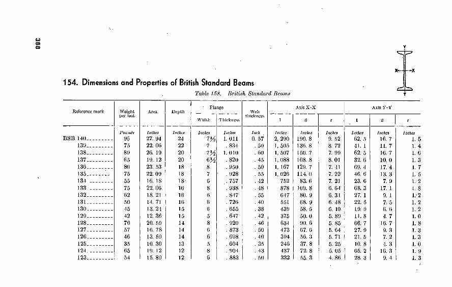
388
Y
'=::#=7
154. Dimensions and Properties of British Standard Beams Table 158. British Standard Beams 4=
Reference mark Weight per foot
Area Depth Flange
Width Thickness
Web thickness
Axis X-X
I S
Axis Y-Y
BSB HO- IS'.)- 138- 137- 136- 135. 134- 133- 132. 131- 130. 129. 128. 127. 126. 125- 124. 123.
Pounds
95 75 89 65 80 75 55 75 62 50 45 42 70 57 46 35 65 54
Inches
27. 94 22. 06 26. 19 19. 12 23. 53 22. 09 16. 18 22. 06 18. 21 14. 71 13. 24 12. 36 20. 59 16. 78 13. 59 10. 30 19. 12 15. 89
Inches
24 22 20 20 18 18 18- 16 16 16 15 15 14 14 14 13 12 12
luches
7'A 7
7A VA 8 7 6 8 6 6 6 5 8 6 6 5 8 6
luches
i. on . 834
1. 010 . 820 . 950 . 928
,. 757 . 938 . 847 . 726 . 655 . 647 . 920 . 873 . 698 . 604 . 904 . 883
Inch
0. 57 . 50 . 60 . 45 . 50 . 55 . 42 . 48 . 55 . 40 . 38 . 42 . 46 . 50 . 40 . 35 . 43 . 50
Inches
2, 290 1, 505 1, 507 1, 088 1, 167 1, 026
752 878 647 551 439 375 634 473 394 246 437 332
Inches
190. 8 136. 8 150. 7 108. 8 129. 7 114. 0
83. 6 109. 8 80. 9 68. 9 58. 5 50. 0 90. 6 67. 6 56. 3 37. 8 72. 8 55. 3
Inches
9. 52 8. 72 7. 99 8. 01 7. 41 7. 22 7. 21 6. 64 6. 31 6. 48 6. 10 5. 89 5. 85 5. 64 5. 71 5. 25 5. 05 4. 86
Inches
62. 5 41. 1 62. 5 32. 6 69. 4 46. 6 23. 6 68. 3 27. 1 22. 5 19. 9 11. 8 66. 7 27. 9 21. 5 10. 8 65. 2 28. 3
Inches
16. 7 11. 7 16. 7 10. 0 17. 4 13. 3
7. 9 17. 1
9. 1 7 -, 5 6. 6 4. 7
16. 7 9. 3 7. 2 4. 3
16. 3 9. 4
Inches
1. 5 1. 4 1. 6 1. 3 1. 7 1. 5 1. 2 1. 8 1.-2 1. 2 1. 2 1. 0 1. 8 1. 3 1.3 1. Ó 1. 9 1. 3

389
122.
121.
120.
119. 118. 117. 116. 115. 114. 113. 112.
111.
110.
109. 108. 107. 106. 105. 104. 103. 102.
101.
44 32 55 40 30 25 50 21
35 28 18 16 25 20 12
20 11
6. 10
5 8.
4
13. 00 9. 45
16. 18 11. 77
8. 85 7. 35
14. 71 6. 18
10. 30 8. 28 5. 30 4 75 7. 37 5. 89 3. 53 5. 88 3. 26 1. 91 2. 94 1. 47 2. 52 1. 18
12 12 10 10 10 10 9. 9 8 8 8 7 6 6 6 5 5 4?í 4 4 3 3
6 5 8 6 5 4^ 7 4 6 5 4 4 5 4H 3 4H 3 1^ 3 m 3 1H
. 717
. 550
. 783
. 709
. 552
. 505
. 825
. 457 . . 648
. 575
. 398
. 387
. 520
. 431
. 377
. 513
. 376
. 325
. 347
. 239
. 332
. 249
40 35 40 36 36 30 40 30 35 35 28 25 41 37 23
. 29 , 22
18 24 17
. 20
. 16
281 192 259 181 127 122 208
81 115 90
.56 40 44 35 21
25 14 7 8 4 4 4
46. 8 32. 0 51. 8 40. 96 25. 4 24. 5 46. 3 18. 0 28. 9 22. 4 13. 9 11. 3 14. 6 11. 6
7. 0 10. 0
5. 5 2. 8 3. 9 i: 8 2. 5 1. 1
4. 94 4. 84 4. 22 4. 17 4. 06 4. 08 3. 76 3. 62 3. 34 3. 29 3. 24 2. 89 2. 44 2. 43 2. 44 2. 06 2. 05 1. 88 1. 63 1.'58 1. 23 1. 19
22. 1
9. 7 54. 7 21. 8
9. 7 6. 5
40. 2 4. 2
19. 5 10. 2 3. 5 3. 4 9. 1 5. 4 1. 5 6. 6 1. 5
. 3 1. 3 .2
1. 3 . 1
7. 4 3. 9
13! 7 7. 3 3. 9 2. 9
11. 5 2. 1 6. 5 4. 1 1. 8 1. 7 3. 6 2. 4 1. 0 2. 9 1. 0
. 3
. 9
. 2
. 8
. 2
1. 3 1. 0 1. 8 1. 4 1. 1
. 9 1. 7
. 8 1. 4 1. 1
. 8
. 8 1. 1 1. 0
. 6 1. 1
. 7
. 4
. 7
. 4
. 7
. 3

390
—X
155. Dimensions and Properties of German Beams Table 159. German Wide-Flange Beams
Nominal size (depth In cemtimeters)
Weight per foot
Area Depth Flange
Width Thickness
Web thickness
Axis U-V Axis Y-Y
I S
10-.-
12...
14.. .
16.. .
18__. 20...
22...
24.. .
26.. .
28-. 30.. . 32.. .
34.. .
36.. .
38--.
40-. 42^_
45.. .
Pounds
14 18 23 31 35 44 48 59 64 76 81 91 92
101 103 110 112 122
Inches
4. 05 5. 32 6. 84 9. 05
10. 20 12. 82 14. 12 17. 20 18. 75 22. 32 23. 87 26. 50 26. 97 29. 76 30. 07 32. 39 32. 86 35. 96
Inches
3. 94 4. 72
■ 5. 51 6. 30 7. 09 7. 87 8. 66 9. 44
10. 24 11. 02 11. 81 12. 60 13. 39 14. 17 14. 96 15. 75 16. 73 17. 72
Inches
3. 937 4. 724 5. 512 6. 299 7. 087 7. 874 8. 661 9. 449
10. 236 11. 024 11. 811 11. 811 11. 811 11. 811 11. 811 11. 811 11. 811 11. 811
Inches
0. 393 . 433 . 472 . 551 . 551 . 630 . 630 . 709 . 709 . 787 . 787 . 866 . 866 . 945 . 945
1. 024 1. 024 1. 102
Inch
0. 256 . 276 . 315 . 354 . 354 . 394 . 394 . 433 . 433 . 472 . 472 . 512 . 512 . 551 . 551 . 551 . 551 . 591
Inches
10. 7 20. 8 36. 5 63. 2 92. 0
142. 9 193. 4 280. 9 361. 6 497. 8 618. 9 774. 8 887. 5
1084. 0 1224. 1 1456. 9 1669. 3 2023. 4
Inches
5. 4 8. 8
13. 2 20. 1 26. 0 36. 3 44. 7 59. 4 70. 8 90. 3
105. 0 123. 3 132. 4 153. 2 163. 6 185. 0 199. 5 228. 2
Inches
1. 63 1. 98 2. 31 2. 65 3. 00 3. 34 3. 69 4. 06 4. 41 4. 72 5. 08 5. 39 5. 71 6. 02 6. 38 6. 69 7. 13 7. 48
Inches
4. 0 7. 6
13. 2 23. 0 32. 7 51. 4 68. 2 99. 7
126. 8 175. 8 216. 4 238. 0 238. 0 259. 7 259. 7 281. 3 281. 3 303. 1
Inches
2. 0 3. 2 4. 8 7. 3 9. 2
13. 1 15. 7 21. 1 24. 9 32. 0 36. 7 40. 4 40. 4 44. 1 44. 1 47. 8 47. 8 51. 4
Inches
1. 00 1. 20 1. 39 1. 59 1. 79 2. 00 2. 20 2. 41 2. 60 2. 81 3. 01 2. 99 2. 97 2. 96 2. 94 2. 95 2. 93 2. 91

391
47J4 50.. . 55.. . 60.. . 05.. . 70. 75.. . 80.. . 85.. . 90- 95.. 100.
124 134 139 153 157 171 175 180 196 201 206 211
36. 42 39. 52 40. 76 44. 79 46. 03 50. 22 51. 61 53. 01 57. 66 59. 05 60. 60 62. 00
18. 70 19. 69 21. 65 23. 61 25. 56 27. 51 29. 47 31. 42 33. 37 35. 33 37. 28 39. 24
11. 811 11. 811 11. 811 11. 811 11. 811 11. 811 11. 811 11: 811 11. 811 11. 811 11. 811 11. 811
1. 102 1. 181 1. 181 1. 260 1. 260 1. 339 1. 339 1. 339 1. 417 1. 417 1. 417 1. 417
591 630 630 662 662 709 709 709 748 748 748 748
2285. 2 2719. 6 3370. 7 4343. 7 5208. 6 6493. 9 7599. 1 8802. 7
10424. 4 12156. 6 13786. 3 15488. 9
244. 7 276. 4 311. 2 368. O 407. 0 471. 1 514. 4 559. 0 637. 1 686. 5 735. 9 787. 2
7. 91 8. 27 9. 09 9. 84
10. 63 11. 38 12. 13 12. 87 13. 62 14. 33 15. 08 15. 79
303. 1 325. 0 325. 0 346. 8 346. 8 368. 7 368. 7 368. 7 390. 8 390. 8 390. 8 391. 0
51. 4 55. 3 55. 3 58. 9 58. 9 62. 5 62. 5 62. 5 66. 1 66. 1 66. 1 66. 1
2. 88 2. 87 2. 82 2. 78 2. 74 2. 71 2. 67 2. 64 2. 60 2. 57 2. 54 2. 51

Table 160. German I-Beams
Nominal size (depth in centimeters)
8—.
10...
12...
14.. . 16.. . 18...
.20...
22...
24.. . 26— 28— 30.. . 32.. . 34.. . 36.. . 38— 40.. . 42!/2.
Weight per foot
Pounds
4 6 8
10 12 15 18 21 24 28 32 36 41 46 51 56 62 70
Area
Inches
1. 17 1. 64 2. 20 2. 84 3. 53 4. 32 5. 19 6. 14 7. 15 8. 28 9. 47
10. 71 12. 06 13. 45 15. 05 16. 58 18. 29 20. 46
Depth
Inches
3. 15 3. 94
'4. 72 5. 51 6. 30 7. 09 7. 87 8. 66 9. 45
10. 24 11. 02 11. 81 12. 60 13. 39 14. 17 14. 96 15. 75 16. 73
Flange
Width Thickness
Inches
1. 654 1. 969 2. 283 2. 598 2. 913 3. 228 3. 543 3. 858 4. 173 4. 449 4. 685 4. 921 5. 157 .5. 394 5. 630 5. 866 6. 102 6. 417
Inches
0. 232 . 268 . 303 . 339 . 374 . 409 . 445 . 480 . 516 . 555 . 598 . 638 . 681 . 720 . 768 . 807 . 850 . 900
Web thickness
Inches
0. 154 . 177 . 201 . 224 . 248 . 272 . 295 . 319 . 343 . 370 . 398 . 425 . 453 . 480 . 512 . 539 . 567 . 602
Axis X-X
I
Inches
1. 9 4. 1 7. 9
13. 8 22. 5 34. 8 51. 4 73. 5
102. 1 137. 9 182. 3 235. 4 300. 6 377. 2 471. 1 576. 8 701. 8 888. 2
Inches
1. 3 2. 2 3. 3 5. 0 7. 2 9. 8
13. 1 17. 0 21. 6 27. 0 33. 1 39. 8 47. 7 56. 3 66. 5 76. 9 89. 1
106. 2
Inches
1. 26 1. 58 1. 89 2. 01 2. 52 2. 83 3. 15 3. 46 3. 78 4. 09 4. 37 4. 69 5. 00 5. 31 5. 59 5. 91 6. 18 6. 57
Axis Y-Y
I
Inches
0. 2 . 3 . 5 . 8
1. 3 2. 0 2. 8 3. 9 5. 3 6. 9 8. 7
10. 8 13. 3 16. 2 19. 6 23. 4 27. 9 34. 6
s
Inches
0. 2 .3 . 5 . 7
1.0 1.3 1. 7 2. 1 2. 5 3. 1 3. 7 4. 4 5. 2 6. 0 7. 0 8. 0 9. 1
10. 7
Inches
0. 36 . 42 . 48 . 55 . 61 . 67 . 74 . 80 . 87 . 91 . 96
1. 01 1. 05 1. 10 1. 14 1. 19 1. 23 1. 30

39
3
45-.
47/2- 50—
55— 60—
77 86 95
112 134
22. 79 25. 27 27. 90 33. 02 39. 37
17. 72 18. 70 19. 69 21. 65 23. 62
6. 693 7. 008 7. 283 7. 874 8. 465
. 957 1. 008 1. 063 1. 181 1. 276.
638 673 709 748 850
1, 101. 5 1, 356. 9 1, 651. 5 2, 382. 8 3, 339. 5
124. 5 145. 2 167. 8 220. 3 282.. 5
6. 97 7. 32 7. 72 8. 50 9. 21
41. 6 50. 2 59. 6 83. 8
112. 2
12. 4 14, 3 16. 4 21. 3 26. 5
1. 35 1. 42 1. 46 1. 58 1. 69

394
X— —x
156. Dimensions and Properties of Indian I-Beams Table 161. Indian I-Beams
Ref No. BSB—
101. 103. 105. 4.. . 104. 6.. .
7.. . 108. 110.
11..
112.
113. 114. 117. 20..
21..
Size
Jnc/ics 3x1 y2
4x1% 4%xl%
4 4 5 5 6 6 7 8 8 x 8 x
10 x 12 x
12 x 6 12 x 6
3 3 3 4% 3 5 4 4 5 6 4% 5
Weight per foot
Founds
4. 0 5. 0 6. 5 9. 5
10. 0 11. 0 18. 0 12. 0 25. 0 16. 0 18. 0 28. 0 35. 0 25. 0 32. 0 44. 0 54. 0
Aren
Inches
1. 18 1. 47 1. 91 2. 79 2. 94 3. 24 5. 29 3. 53 7. 37 4. 71 5. 30 8. 28
10. 30 7. 35 9. 41
12. 95 15. 88
Depth
Inches
3 4 4% 4 4 5 5 6 G 7 8 8 8
10 12 12 12
Flange
Width
Inches
W 1% 1% 3 3 3 4/2
3 5 4 4 5 6 4% 5 6
. 6
Thick- ness
Inches
0. 249 . 239 . 325 . 336 . 347 . 376 . 448 . 377 . 520 . 387 . 398 . 575 . 648 . 505 . 550 . 717 . 717
Wei) thick- ness
Inches
0. 160 . 170 . 180 . 220 . 240 . 220 . 290 . 230 . 410 . 250 . 280 . 350 . 350 . 300 . 350 . 400 . 625
Axis X-X
Inches
1. 7 3. 7 0. 7 7. 5 7. 8
13. 7 22. 7 21. 0 43. 7 39. 5 55. 6 89. 7
115. 1 122. 3 192. 0 281. 0
Inches
1. 1 1. 8 2. 8 3. 8 3. 9 5. 5 9. 1 7. 0
14. 6 11. 3 13. 9 22. 4 28. 8 24. 5 36. 8 52. 8
Inches
1. 19 1. 58 1. 88 1. 64 1. 63 2. 05 2. 07 2. 44 2. 44 2. 89 3. 24 3. 29 3. 34 4. 08 4. 84 4. 94
Axis Y-Y
Inches
. 13
. 19
. 26 1. 28 1. 33 1. 45 5. 66 1. 46 9. 10 3. 37 3. 51
10. 19 19. 54
6. 49 9. 69'
22. 12
Inches
0. 17 . 21 . 30 . 85 . 88 . 97
2. 52 . 97
3. 64 1. 69 1. 75 4. 08 6. 51 2. 88 3. 88 7. 37
Inches ¡
0. 32 . 36 . 37 . 68 . 67 . 67
1. 03 . 04
1. 11 . 84 . 81
1. 11 1. 38
•. 94 1. 01 I. 30

125. 25.. 26.. 130. 131. 134. 137. 139.
6...
8...
17.. 10..
18..
NBSB
13 15 15 16 18 18 x 6 20 22
7 9
10 12 24
6/2 7
3/2
4 5 5
7K 24 x iVï 24 x 7/2
35. 0 42. 0 59. 0 45. 0 50. 0 55. 0 65. 0 75. 0
15. 0 21. 0
30. 0 30. 0 90. 0 95. 0
100. 0
10. 30 12. 35 17. 35 13. 24 14. 71 16. 18 19. 12 22. 06
4. 42 6. 18 8. 82 8. 82
26. 47 27. 91 29. 40
13 15 15 16 18 18 20 22
7 9
10 12
24 24 24
5 5 6
6 6 6
6/2 7
3/2
4 5 5
7K 7/2
7/2
. 604
. 647
. 880
. 665
. 726
. 757 . 820 . 834
. 398
. 460
. 552
. 507
. 984 . 984 . 984
350 420 500 380 400 420
. 450 , 500
. 250
. 300
. 360
. 330 . 520 . 578 . 625
246. 0 375. 0 559. 0 439. 0 551. 0 752. 0
1088. 0 1505. 0
35. 9 81. 1
127. 0 180. 0
43. 6 57. 1 83. 9 65. 6
■ 77. 3 93. 5
122. 6 152. 4
10. 3 18. 0 29. 3 34. 5
5. 25 5. 89 6. 02 6. 09
.6. 48 7. 21 8. 01 8. 72
2. 85 3. 62 4. 06 4. 84
10. 82 U. 81 28. 22 19. 87 22. 47 23. 63 32. 56 41. 07
2. 41 4. 15 9. 73 8. 77
4. 33 4. 72 9. 41 6. 62 7. 49 7. 88
10. 02
11. 73
1. 38 2. 07 3. 89 3. 51
1. 03 .. 98
!.. 27 1, 23 1, 24 1; 21 1, 31 1. 36
74 82 05 00

396
157. Dimensions and Properties of Italian I-Beams
Table 162. Italian I-Beams
T «-■-1-~»
+ Profllo
Depth in
milli- meters
80.. 100.
120.
140. 160. 180. 200.
220.
240. 250. 260. 280. 300. 320. 340. 360.
Milli- meters
80 100 120
140 160 180 200 220
240 250 260 280 300 320 340 360
Weight per fuoL
Pounds
4. 0 5. 6 7. 5 9. 7
12. 0 14. 7 17. 7 21. 4 24. 3 26. 1 28. 2 32. 2 36. 4 41. 0 45. 7 51'. 2
Area
Inches
1. 18 1. 64 2. 20 2. 84 3. 54 4. 32 5. 20 6. 14 7. 14 7. 67 8. 29 9. 47
10. 70 12. 05 13. 45 15. 04
Depth in
Inches
Inches
3. 15 3. 94 4. 72 5. 51 6. 30 7. 09 7. 88 8. 66 9. 45 9. 85
10. 25 11. 02 11. 81 12. 60 13. 39 14. 17
Flange
Width
Inches
1. 654 1. 969 2. 283 2. 598 2. 913 3. 228 3. 543 3. 858 4. 173 4. 331 4. 449 4. 685 4. 921 5. 157 5. 394 5. 630
Thick- ness
Inches
0. 232 . 268 . 303 . 339 . 374 . 409 . 445 . 481 . 516 . 535 . 556 . 599 . 638 . 681 . 721 . 767
Web thick- ness
Inches
0. 154 . 177 . 200 . 224 . 248 . 272 . 295 . 319 . 343 . 354 . 370 . 398 . 425 . 453 . 480 . 519
Axis X-X
Inches
1. 9 4. 1 7. 9
13. 7 22. 4 34. 7 51. 4 73. 5
102. 1
119. 3 137. 9 182. 3 235. 4 300. 5 377. 1 471. 0
Inches
1. 2 2. 1 3. 3 5. 0 7. 1 9. 8
13. 1 17. 0 21. 6 22. 8 27. 0 33. 1 39. 8 47. 7 56. 3 66. 5
Inches
1. 28 1. 58 1. 89 2. 20 2. 52 2. 83 3. 15 3. 46 3. 78 3. 93 4. 09 4. 37 4. 69 5. 00 5. 31 5. 59
Axis Y-Y
Inches
0. 15 . 29 . 51 . 84
1. 31 1. 95 2. 78 3. 89 5. 28 6. 13 6. 89 7. 19
10. 83 13. 33 16. 19 19. 65
Inches
0. 18 . 30 . 45 . 65 . 90
1. 21 1. 58 2. 02 2. 53 2. 83 3. 11 3. 72 4. 39 5. 16 5. 99 6. 95
Inches
0. 36 . 42 . 48 . 55 . 61 . 67 . 74 . 80 .86 . 89 . 91 . 96
1. 00 1. 05 1. 10 1. 14

39
7
380. 400. 425. 450. 475. 500. 550. 600.
380 400 425 450 475 500 550 600
56. 4 62. 2 69. 9 77. 5 86. 0 94. 9
112. 5 133. 7
16. 57 18. 28 20. 45 22. 77 25. 25 27. 88 32. 99 39. 37
14. 96 15. 75 16. 73 17. 72 18. 7Ó 19. 69 21. 65 23. 62
5. 866 6. 102 6. 417 6. 693 7. 008 7. 283 7. 874 8. 464
. 807
. 851
. 905
. 958 1. 008 1. 063 1. 181 1. 276
539 , 567 , 602 . 638 . 673 , 709 . 748. . 850
576. 7 701. 6 888. 0
1, 101. 4 1, 356. 7 1, 651. 1 2, 382. 4 3, 334. 2
76. 9 89. 1
106. 1 124. 5 144. 9 167. 8 220. 3 282. 2
5. 91 6. 18 6. 57 6. 97 7. 32 7. 72 8. 50 9. 21
23. 42 27. 82 34. 52 41. 43 50. 15 59. 52 83. 78
112. 39
7. 00 9. 09
10. 74 12. 39 14. 28 16. 35 21. 23 26. 54
1. 19 1. 23 1. 30 1. 35 1. 41 1. 46 1. 58 1. 69

398
158. Dimensions and Properties of Portuguese I-Beams
Table 16S. Porlxigucsc Ï-Bcams
T 1 —»
4=
Section
10.
12.
14.
16.
18. 20.
22.
24.
26.
28. 30. 32.
34.
36.
38-
Depth in
milli- meters
Milli- meter«
100 120 140 160 180 200 220 240 260 280 300 320 340 360 380
Weight I ter foot
Pounds
13. 8 18. 1 23. 3 30. 1 34. 7 43. 6 48. 0 58. 7 63. 7 75. 9 81. 3 90. 7 92. 1
1.00. 8 102. 8
Aren
Inches
4. 05 5. 32 6. 84 9. 05
10. 20 12. 82 14. 12 17. 21 18. 76 22. 32 23. 87 26. 51 26. 97 29. 76 30. 07
Depth in
inches
Inches
3. 94 4. 72 5. 51 6. 30 7. 09 7. 88 8. 66 9. 45
10. 24 11. 02 11. 81 12. 60 13. 39 14. 17 14. 96
Flange
Width
Inches
3. 937 4. 724 5. 512 6. 299 7. 086 7. 874 8. 661 9. 449
10. 236 11. 024 11. 811 11. 811 11. 811 11. 811 11. 811
Thick- ness
Inches
0. 394 . 433 . 472 . 551 . 551 . 630 . 630 . 709 . 709 . 788 . 788 . 866 . 866 . 945 . 945
Web thick- ness
Inches
0. 256 . 276 . 315 . 354 . 354 . 394 . 394 . 433 . 433 . 472 . 472 . 512 . 512 . 551 . 551
Axis X-X
Inches
10. 7 20. 8 36. 5 63. 2 92. 0
142. 9 193. 4 280. 8 361. 5 497. 7 618. 8 774. 6 887. 3
1, 083. 8 1, 223. 8
Inches
5. 5 8. 8
13. 2 20. 1 26. 0 36. 3 44. 7 59. 4 70. 8 90. 3
105. 0 123. 3 132. 4 153. 2 163. 5
Inches
1. 63 1. 98 2. 31 2. 65 3. 00 3. 34 3. 69 4. 13 4. 41 4. 72 5. 08 5. 39 5. 71 6. 02 6. 38
Axis Y-Y
Inches
4. 0 7. 6
13. 2 23. 0 32. 7 51. 4 68. 2 99. 7
126. 8 175. 8 216. 4 238. 0 238. 0 259. 7 259. 7
Inches
2. 0 3. 2 4. 8 7. 3 9. 2
13. 1 15. 7 21. 1 24. 8 31. 9 36. 6 40. 3 40. 3 44. 0 44. 0
Inches ¡
1. 00 1. 20 1. 39 1. 59 1. 79 2. 00 2. 20 2. 41 2. 60 2. 81 3. 01 2. 99 2. 97 2. 96 2. 94
i

533506
Ci o
to Ci
40-- 42}L 45.- 47>í- 50- . 55-. 60. - 65.- 70. . 75-- 80-- 85-. 90. _ 95-- 100-
400 425 450 475 500 550 600 650 700 750 800 850 900 950
1, 000
110. 2 111. 5 122. 3 124. 3 134. 4 139. 1 152. 5 157. 2 170. 6 175. 4 180. 0 196. 2 200. 9 206. 3 211. 0
32. 40 32. 86 35. 96 36. 43 39. 53 40. 77 44. 80 46. 04 50. 22 51. 62 53. 01 57. 66 59. 05 60. 61 62. 00
15. 75 16. 73 17. 71 18. 70 19. 59 21. 65 23. 62 25. 59 27. 56 29. 53 31. 50 33. 46 35. 43 37. 40 39. 37
11. 811 11. 811 11. 811 11. 811 11. 811 11. 811 11. 811 11. 811 11. 811 11. 811 11. 811 11. 811 11. 811 11. 811 11. 811
1. 024 1. 024 1. 102 1. 102 1. 181 1. 181 1. 260 1. 260 1. 339 1. 339 1. 339 1. 417 1. 417 1. 417 1. 417
551 551 591 591 630 630 669 669 709 709 709 748 748 748 748
1,456. 6 1, 668. 9 2, 023. 0 2, 284. 8 2, 719. 1 3, 370. 0 4, 342. 8 5, 207. 5 6, 492. 6 7, 597. 5 8, 800. 9
10, 662. 5 12, 154. 1 13, 763. 5 15, 485. 7
184. 9 199. 5 228. 2 244. 7 276. 4 311. 2 368. 0 407. 0 471. 1 514. 4 558. 9 637. 0 686. 5 735. 9 787. 2
6. 69 7. 13 7. 48 7. 91 8. 27 9. 09 9. 84
10. 62 11. 37 12. 12 12. 87 13. 62 14. 33 15. 07 15. 78
281. 3 281. 3 303. 1 303. 1 325. 0 325. 0 346. 8 346. 8 368. 7 368. 7 368. 7 390. 8 390. 8 390. 8 391. 0
47. 7 47. 7 51. 3 51. 3 55. 0 55. 0 58. 7 58. 7 62. 2 62. 2 62. 2 65. 9 65. 9 65. 9 65. 9
(•> O ■O
2. 95 2. 93 2. 91 2. 88 2. 87 2. 82 2. 78 2. 74 2. 71 2. 67 2. 64 2. 60 2. 58 2. 54 2. 51

40
0
159. Dimensions and Properties of Russian I-Beams
Number of profile
10.. 12..
14.. 16.. 18.. 20a. 20b. 22a. 22b. 24a. 24b.
• 27a. 27b. 30a. 30b. 30s.
Table 164. Russian I-Beams
f X
Depth In milli-
meters
Milli- meters
100 120 140 160 180 200 200 220 220 240 240 270 270 300 300 300
Weight per foot
Pounds
7. 5 O! 4
11. 4 .13. 8 16. 2 18. 7 20. 9 22. 2 24. 5 25. 1 27. 7 28. 8 31. 7 32. 3 35. 4 38. 6
Area
Inches
2. 21 2. 76 3. 33 4. .05 4. 74 5. 50 6. 12 6. 51 7. 19 7. 39 8. 15 8. 46 9. 30 9. 49
10. 41 11. 38
Depth In Inches
Inches
3. 94 4. 72 5. 51 6. 30 7. 09 7. 87 7. 87 8. 66 8. 66 9. 45 9. 45
10. 63 10. 63 11. 81 11. 81 11. 81
Flange
Width Thickness
Inches
2. 677 2. 913 3. 149 3. 465 3. 701 3. 937 4. 016 4. 331 4. 409 4. 567 4. 645 4. 803 4. 881 4. 961 5. 039 5. 118
Inches
0. 299 . 331 . 358
' . 390 . 421 . 449 . 449 . 484 . 484 . 512 . 512 . 539 . 539 . 567 . 567 . 567
Web thickness
Inches
0. 177 . 197 . 217 . 236 . 256 . 276 . 354 . 295 . 374 . 315 . 394 . 335 . 413 . 354 . 433 . 512
Axis X-X
Inches
5. 9 10. 5 17. 1 27. 1 39. 9 56. 9 60. 1 81. 7 85. 8
109. 8 115. 3 157. 3 165. 0 215. 0 225. 8 236. 6
Inches
3. 0 4. 4 6. 2 8. 6
11. 3 14. 5 15. 3 18. 9 19. 8 23. 3 24. 4 29. 6 31. 1 36. 4 38. 3 40. 1
. Inches
1. 63 1. 95
• 2. 26 2. 59 2. 90 3. 21 3. 14 3. 54 3. 46 3. 85 3. 77 4. 29 4. 21 4. 76 4. 65 4.57
Axis Y-Y
I S
Inches
0. 79 1. 13 1. 55 2. 24 2. 93 3. 79 4. 06 5. 40 5. 74 6. 73 7. 13 8. 29 8. 79 9. 61
10. 14 10. 69
Inches
0. 59 . 77 . 98
1. 29 1. 59 1. 92 2. 02 2. 50 2. 61 2. 95 3. 08 3. 45 3. 59 3. 87 4. 02 4. 18
Inches
0. 60 . 63 . 68 . 74 . 79 . 84 . 81 . 91 . 89 . 95 . 94 . 99 . 97
1. 00 . 98 . 97

401 33a 33b 33s 3ba_ 30b 30s 40a 40b 40s 45a 45b 45s 50a 50b 50s 55a 55b 55s 00a 00b 00s
330 330 330 300 300 300 400 400 400 450 450 450 500 500 500 550 550 550 000 000 000
35. 9 39. 4 42. 9 40. 3 44. 1 47. 8 45. 4 49. 0 53. 8 54. 0 58. 7 03. 5 02. 9 07. 9 73. 2 70. 0 70. 0 82. 7 79. 3 80. 0 92. 1
10. 50 11. 58 12. 00 11. 83 12. 94 14. 00 13. 35 14. 59 15. 81 15. 81 17. 21 18. 00 18. 45 20. 00 21. 55 20. 77 22. 48 24. 18 23. 41 25. 27 27. 13
12. 99 12. 99 12. 99 14. 17 14. 17 14. 17 15. 75 15. 75 15. 75 17. 71 17. 71 17. 71 19. 09 19. 09 19. 09 21. 05 21. 05 21. 05 23. 02 23. 02 23. 02
5. 118 5. 190 5. 275 5. 354 5. 433 5. 511 5. 590 5. 009 5. 748 5. 900 5. 984 0. 002 0. 220 0. 299 0. 378 6. 535 0. 014 0. 092 6. 929 7. 008 7. 080
591 591 591
. 022 622
. 622
. 050
. 650
. 650
. 709
. 709
. 709
. 787
. 787
. 787
. 827
. 827
. 827
. 866
. 806
. 800
. 374 453
. 531 , 394 . 472 . 551 . 413 . 492 . 571 . 453 ! 531 . 610 ' 472 . 551 . 630 . 492 . 571 . 650 . 512 . 591 . 609
285. 8 300. 3 314. 7 378. 6 397. 1 415. 8 521. 7 547. 2 572. 9 774. 4 810. 9 847. 4
1, 116. 2
1, 166. 4 1, 216. 4 1, 510. 1 1, 576. 7 1, 643. 2 2, 014. 3 2,100. 8 2, 187. 3
44. 0 46. 2 48. 4 53. 4 56. 1 58. 7 66. 5 09. 0 72. 0 87. 3 91. 5 95. 8
113. 5 118. 4 120. 9 139. 7 145. 8 1.51. 9 170. 9 178. 2 185. 5
5. 20 5. 08 5. 00 5. 67 5. 55 5. 43 6. 26 6. 14 5. 98 6. 97 6. 85 6. 73 7. 76 7. 64 7. 48 8. 50 8. 35 8. 23 9. 25 9. 13 8. 98
11. 05 11. 63 12. 25 13. 26 13. 98 14. 70 15. 85 16. 62 17. 46 20. 53 21. 47 22. 53 26. 90 28. 10 29. 30 32. 91 34. 11 35. 55 40. 83 42. 52 44. 20
4. 31 4. 47 4. 64 4. 95 5. 14 5. 33 5. 69 5. 87 6. 08 6. 96 7. 20 7. 44 8. 66 8. 91 9. 21
10. 01 10. 37 10. 68 11. 78 12. 14 12. 51
1. 06 1. 00
. 99 1. 06 1. 04 1. 02 1. 09 1. 07 1. 04 1. 14 1. 12 1. 10 1. 21 1. 19 1. 17 1. 26 1. 24 1. 21 1. 32 1. 30 1. 28
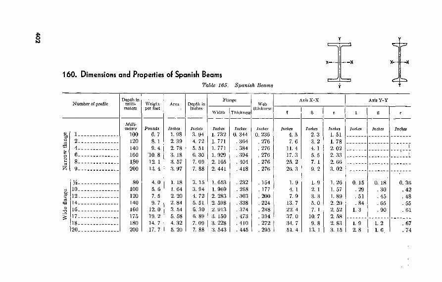
Wid
e fl
ange
Nar
row
fla
nge
A O to
160. Dimensions and Properties oí Spanish Beams Table 165. Spanish Beams
Y
X X
Ir X- —oc
4*
Number of profile
10.
12.
14.
16-
17.
18- Î20-
Depth in milli-
meters
Milli- meters
100 120 140 160 1.80 200
80 100 120 140 160 175 180 200
Weight per foot
Pounds
6. 7 8. 1 9. 4
10. 8 12. 1 13. 4
4. 0 5. 6 7. 5 9. 7
12. 0 19. 2 14. 7 17. 7
Area
Inches
1. 98 2. 39 2. 78 3. 18 3. 57 3. 97
1. 18 ]. 64 2. 20 2. 84 3. 54 5. 58 4. 32 5. 20
Depth in inches
Inches
3. 94 4. 72 5. 51 6. 30 7. 09 7. 88
3. 15 3. 94 4. 72 5. 51 6. 30 6. 89 7. 09 7. 88
Flange
Width Thickness
Inches
1. 732 1. .771 1. 771 1. 929 2. 165 2. 441
1. 653 1. 969 2. 283 2. 598 2. 913 3. 150 3. 228 3. 543
Inches
0. 344 . 364 . 384 . 394 . 404 . 418
. 232
. 268
. 303
. 338
. 374
. 473
. 410
. 445
Web thickness
Inches
0. 236 . 276 . 276 . 276 . 276 . 276
. 154
. 177
. 200
. 224
. 248
. 394
. 272
. 295
Axis X-X Axis Y-Y
Inches
4. 5 7. 6
11. 4 17. 3 25. 2 26. 3
1. 9 4. 1 7. 9
13. 7 22. 4 37. 0 34. 7 51. 4
Inches
2. 3 3. 2 4. 1 5. 5 7. 1 9. 2
1. 9 2. 1 3. 3 5. 0 7. 1
10. 7 9. 8
13. 1
Inches
1. 51 1. 78 2. 02 2. 33 2. 66 3. 02
1. 26 1. 57 1. 89 2. 20 2. 52 2. 58 2. 83 3. 15
Inches Inches
0. 15 . 29 . 51 . 84
1. 3
1. 9 2. 8
Inches
0. 18 . 30 . 45 . 65 . 90
1. 2 1. 6
0. 36 . 42 . 48 . 55 . 61
. 67
. 74
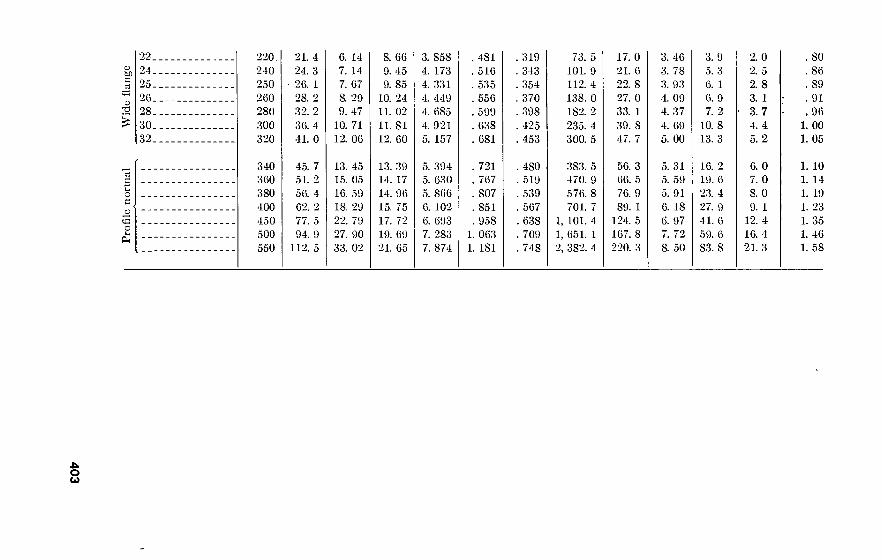
Pro
file
norm
al
Wid
e fl
ange
22 24 25 26 28. 30 32
220.
240 250 260 280 300 320
21. 4 24. 3 26. 1 28. 2 32. 2 36. 4 41. 0
6. 14 7. 14 7. 67 8. 29 9. 47
10. 71 12. 06
8. 66 9. 45 9. 85
10. 24 11. 02 11. 81 12. 60
3. 858 4. 173 4. 331 4. 449 4. 685 4. 921 5. 157
. 4SI
. 516
. 535
. 556
. 599
. 638
. 681
319 343 354 370 398 425 453
73. 5 101. 9 112. 4 138. 0 182. 2 235. 4 300. 5
17. 0 21. 6 22. 8 27. 0 33. 1 39. 8 47. 7
3. 46 3. 78 3. 93 4. 09 4. 37 4. 69 5. 00
3. 9 5. 3 6. 1 6. 9 7. 2
10. 8 13. 3
2. 0 2. 5 2. 8 3. 1 3. 7 4. 4 5.2
. SO
. 86
. 89
. 91
. 96 1. 00 1. 05
340 360 380 400 450 500 550
45. 7 51. 2 56. 4 62. 2 77. 5 94. 9
112. 5
13. 45 15. 05 16. 59 18. 29 22. 79 27. 90 33. 02
13. 39 14. 17 14. 96 15. 75 17. 72 19. 69 21. 65
5. 394 5. 630 5. 866 6. 102 6. 693 7. 283 7. 874
. 721
. 767
. 807
. 851
. 958 1. 063 1. 181
480 519 539 567 638 709 748
383. 5 470. 9 576. 8 701. 7
1, 101. 4 1, 651. 1 2, 382. 4
56. 3 66. 5 76. 9 89. 1
124. 5 167. 8 220. 3
5. 31 5. 59 5. 91 6. 18 6. 97 7. 72 8. 50
16. 2 19. 6 23. 4 27. 9 41. 6 59. 6 S3. 8
6. 0 7. 0 8. 0 9. 1
12. 4 16. 4 21. 3
1. 10 1. 14 1. 19 1. 23 1. 35 1. 46 1. 58
-u o u

161. Safe Loads on Ansies and Steel Pipes a. Safe Loads on Angles Used as Beams. Allowable uniform load
in kips for angles supported laterally and with longer leg vertical are shown in table 166.
Table 166. Safe Loads on Angles in Kips
Size
8 x 8 x 1 6 x 6 x y¡a 5 x 5 x % 4 x 3 x 'A 4 x 3 x 3A
716 3K X 3/2 X Me-
3x3x/ 2/ x 2 x K—■ 8x 6x % 8 x 4 x 'A 6 x 4 x % 5 x 3/2 x 5 x 3/ x Zo--- 4 x 3/ x Zo--. 4x3x/i 4x3x% 4 x 3 x Zo 3/ x 3 x
Span in feet
42 10. 9 10. 4
5. 1 4. 0 3. 2 2. 6 1. 5
31 20
8. 8 6. 1 5. 1 3. 5 5. 1 4. 0 3. 2 2. 1
30 7. 8 7. 4 3. 6 2. 9 2. 3 1. 9
22 14. 3
6. 3 4. 4 3. 6 2. 5 3. 6 2. 9 2. 3 1. 5
26 6. 8 6. 5 3. 2 2. 5 2. 0 1. 6
19. 5 12. 5
6. 5 3. 8 3. 2 2. 2 3. 2 2. 5 2. 0
23 6. 1 5. 8
17. 3 11. 1
4. 9 3. 4 2. 8 1. 9
21 5. 5 5. 2
15. 6 10. 0
4. 4 3. 1 2. 5
17. 6 4. 6
13. 0 8. 3 3. 7
15. 0 3. 9
11. 1 7. 1
16
13. 2
9. 7 6. 2
18
11. 7
6. (S'o/e Loads on Steel-Pipe Columns. Allowable concentric loads in kips are given in table 167. The loads below the heavy lines are for secondary members with Ijr ratios between 120 and 200. For main members of these lengths, use the column formula in paragraph 149a and radii of gyration in paragraph 151.
Table 167. Safe Loads on Pipes
Standard
Unbraced length (feet)
6—
8-.
10-
12,
14- 16- 18. 20-
22_
Nominal diameter—weight per foot
49.56 43.7'
246 244 243 240 237 234 231 227 222
217 216 214 212 210 207 204 200 196
to
40.48 34.24 31.20
200 199 196 194 190 187 182 178 172
169 168 166 164 161 158 154 151 146
154 153 151 149 147 144 141 137 133
28.55 24.70
140 138 136 133 129 125 121 115 109
121 120 118 115 112 109 105 100
95
18.97
92 90 86 82 79 74 69 63 56
14.62
70 68 64 61 56 51 45
41 37
50 47 44 40 34
30 26 23 21
3H
42 38 35 30
25 22 19 17 15
7.58
33 30 26
21 18 16 13
404
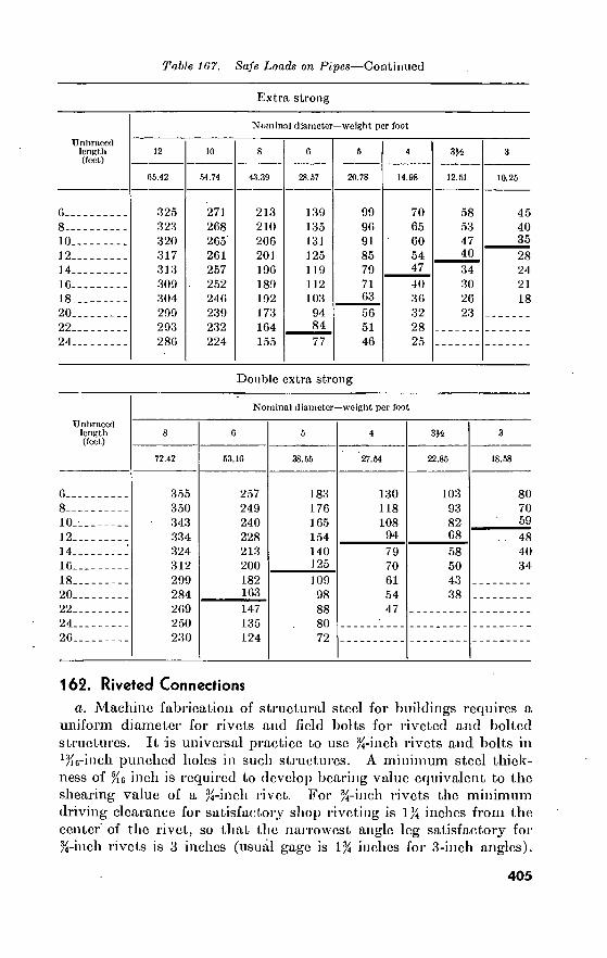
Table 167. Safe Loads on Pipes—Continued
Extra strong
Unbraced length (feet)
6-
8-
10,
12.
14- 10- 18- 20-
22-
24.
Nominal diameter—weight per foot
05.42
325 323 320 317 313 300 304 200 203 280
54.74
271 208 205' 201 257 252 240 230 232 224
43.3!)
213 210 200 201 100 180 102 173 104 155
28.57
130 135 131 125 1 10 112 103 04 84_
77
20.78
00 00 91 85 79 71
03_ 50 51 40
3«
70 65 60 54 47 40 36 32 28 25
12.51
58 53 47 40 34 30 26 23
10.25
45 40
_35
28 24 21 18
Double extra strong
Unbraced length (feet)
0- 8-
10.
12. 14- 10-
18- 20-
22.
24. 26-
72.42
355 350 343 334 324 312 299 284 209 250 230
Nominal diameter—weight per foot
53.10
257 249 240 228 213 200 182 163 147 135 124
38.55
183 176 105 154 140 125 100 08 88 80 72
27.54
130 118 108
94
79 70 61 54 47
314
22.85
103 93 82 08 58 50 43 38
18.58
80 70 59
48 40 34
162. Riveted Connections a. Machine fabrication of structural steel for buildings requires a
uniform diameter for rivets and field bolts for riveted and bolted structures. It is universal practice to use %-inch rivets and bolts in ‘Ke-inch punched boles in such structures. A minimum steel thick- ness of %6 inch is required to develop bearing value equivalent to the shearing value of a %-inch rivet. For %-inch rivets the minimum driving clearance for satisfactory shop riveting is 1% inches from the center of the rivet, so that the narrowest angle leg satisfactory for %-inch rivets is 3 inches (usual gage is 1% inches for 3-inch angles).
405

The lightest member composed of a pair of angles for a riveted truss is thus two angles 3 by 2% by inches, and the minimum gusset-plate thickness is thus inch. The above factors affect the spacing and panel arrangements of riveted trusses. Usual gages for various angles (in inches) are—
Leg.
g—- gi-- g2--
8 4K 3 3
7 4 2H 3
6 3H 2K 2/2
5 3 2 1%
4 2H
3K 2
3
1JÍ 2M 1%
2
1# 1*4 1
1/2 %
1% 7/
l>4 *4
¿>. The minimum WF section suitable for use as a column to receive the ends of floorbeams from two directions 90° apart is an 8- by 6/2- inch WF, 24 pounds per foot. Seated connections with rivets 3% inches center to center can be riveted or bolted to flanges and web of this section. The usual rivet gage is 3% inches in WF beam flanges 6% to 7% inches wide, and 5% inches in flanges 8 inches and wider. The 8- by 8-inch WF, 31 pounds per foot, is therefore the lightest section on which standard connection angles can be riveted or bolted to the flanges.
163. Welded Connections a. Types of Welded Joints. The joints shown in figure 76 are types
accepted without qualification under the A.W.S. code and under the A.I.S.C. specifications.
b. Welding Symbols for Use on Drawings. The symbols shown in figure 77 are those developed by the American Welding Society for use on drawings specifying arc or gas welding. See also TM 5-704.
c. Effective Areas of Weld Metal. The strength of welded connec- tions is based on unit stresses for welds as given in paragraph 149a and on effective areas of weld metal as shown in table 168.
406

Roof need not* be chipped ,before welding second ,» .• iside.-r-^ ràto4
TIJ . '-Si ^5 ~ T min.
Mo^.T
OPEN SQUARE.-BUTT JOINT WELDED BOTH SIDES
T* unlimifed 60—mL
-JU= I toi-I
=f TitoB
0 to ta
SINGLE-V BUTT JOINT WELDED BOTH SIDES
unlimited 5V
Uta T T taTZTi*
Lower edge for/ horizonfol position
o"to¿ min.
SINGLE BEVEL BUTT JOINT WELDED BOTH SIDES
T-unlimited A5 min
=£
¿to s
SINGLE-V BUTT JOINT, WELDED ONE SIDE ON BACKING STRUCTURE
T-unlimited
toi
Lower edge for/-* horizontal position.
SINGLE BEVEL BUTT JOINT, WELDED ONE SIDE ON BACKING STRUCTURE
T-unlimited &o°m/0
h'toi
*=£ O'to^
T-unlimited o^irt
~Q m|n-
DOUBLE-V BUTT JOINT
% to
t O’to,4
h T, -Hto¿
-■j rnin. DOUBLE BEVEL BUTT JOINT
Í45-ln horizontal position dindzs-in other „ ,«
[positions Ätof
“3 it tot 2 m
O'to¿ T- unlimited
SINGLE-J BUTT JOINT WELDED BOTH SIDES
{45-in horizontal position 25-in others—**. |- posit ions-^^l x f“52toa &-in orneo— osif ions-^^*l \
{ 4toÜ
TfztoS o'to I
DOUBLE-J BUTT JOINT
T-unlimited
The above Joints are accepted without qualification under the A. W. S. Code and under A. I. -8. C.'Specification Sect. 24 (b).
Figure 76. Types of welded joints.
407

45*-In horîronfol posIKon 20* in ofhep poslfions
o’to¿ ^ min.-
T-unlimifcd
SINGLE-U BUTT JOINT WELDED BOTH SIDES
f45* In horizontal position Min. 20* in other .• ,•
posirions
.to,%' min.
h to ¿ 0*tOï -unlimited
DOUBLE-U BUTT JOINT
=P e Effective Throat Thickness «¿T
Max T »
SQUARE- BUTT JOINT WELDED ONE SIDE
Root need not be chipped before weldino second side.— —
i ¿toé“
Effective Throaf Thickness"¿T Max.T-^"
SQUARE-BUTT JOINT WELDED BOTH SIDES
C± % _jrk tok
T min.
Effective Throaf Thickness"^T Max.T *
OPEN SQUARE-BUTT JOINT WELDED ONE SIDE
T-unllmifed cp rnln ¿“toé*
> /,
-O'toJ “Ä mm.
Effective Throat Thickness • ^T SINGLE-V BUTT JOINT
WELDED ONE SIDE
-unlimited
n o toi
min kOwer edge for. _ orizontdl position Effective ThrootThickness»^T SINGLE BEVEL BUTT JOINT
WELDED ONE SIDE
T > T,
n=9. . |s| 5Ti mm. |s|
not less than l" S «as required
DOUBLE FILLET WELDED LAP JOINT
SEE A. I. S. C. SPEC. SECT. 25 (c)
Edge o7 pTdfo
Max. Effective Fillet »T-¿"
Edge of rolled section
Mox. Effective Fillet ■ ^ T
-.707 T
Max. Effective-Fillet *T
EDGE FILLET WELDS SEE A. I. S. C. SPEC. SECT. 24 (d)
The above ioints are accepted without qualification under the A. W. S. Code and under A. I 8. C. Specification Sect. 24 (b).
Figure 76.—Continued
408

Table 168. Effective Weld Areas
Type of weld Eflcctive length Effective throat thickness
Butt welds, complete penetration.
Butt welds, incomplete penetration.
Fillet welds 1 -
Plug and slot welds
Fillet welds in holes or slots.
Thickness of thinner part joined.
75% of thickness of thinner part joined.
Shortest distance from root to face (0.707 times nominal size for an equal-leg 45° weld.)
Shearing area is nominal area of hole or slot in plane of faying (contact) surface.
Shearing area is effective area of fillet, but not to exceed nominal area of hole or slot.
Width of part joined...
Over-all length of full- size fillet, including returns.
ARC AND GAS WELDING SYMBOLS TYPE OF WELD
BEAD FILLET SQUARE
GROOVE BEVEL
PLUG & SLOT
FIELD WELD
WELD ALL
AROUND FLUSH
II 1/ Y7 O LOCATION OF WELDS
ARROW (OR N EARj) SIDE OF JOINT
OTHER (OR. FAR) SIDE OF JOINT
BOTH SIDES OF JOINT
SEE FIELD NOTE S_ ' WELD
jS1
¿ct-
NCLUDED qo°__ Ä 40°^
CL
SIZE.-
3 ± SlZExS i
“SIZE WFLUSH -SIZE UlZE V*ROOT /3EE \ OPPNING-/NOTE
1.1— yWEUO ALU •INCREMENTt AROUND*!
‘IN.LEN6TH - 1
ET IF .GEQEDJ 11^
OFFSET l , STAGGERED-!
< > 1 «RUUNU-I
PITCH OF INCREMENTS
1. THE SIDE OF THE JOINT TO WHICH THE ARROW POINTS IS THE ARROW (OR NEAR) SIDE AND THE OPPOSITE SIDE OF THE JOINT IS THE OTHER (OR FAR) SIDE.
2. ARROW SIDE AND OTHER SIDE WELDS ARE SAME SIZE UNLESS OTHERWISE SHOWN.
9 SYMBOLS APPLY BETWEEN ABRUPT CHANGES IN DIRECTION OF JOINT OR AS DIMENSIONED, (EXCEPT WHERE ALL AROUND SYMBOL IS USED). --
4 ALL WELDS ARE CONTINUOUS AND OF USER’S STANDARD PRO- PORTIONS. UNLESS OTHERWISE SHOWN
5 TAIL OF ARROW USED FOR SPECIFICATION REFERENCE (TAIL MAY BE OMITTED WHEN REFERENCE NOT USED.)
E. G. “C. A."—AUTOMATIC SHIELDED CARBON ARC
••S. A."—AUTOMATIC SUBMERGED ARC
8 IN JOINTS IN WHICH ONE MEMBER ONLY IS TO BE GROOVED. ARROW POINTS TO THAT MEMBER
7. DIMENSIONS OF WELD SIZES. INCREMENT LENGTHS. AND SPAC- INGS. IN INCHES.
Figure 77. Welding symbols
409

.. G FtfT Fi fling-II» teams where Má MUif ispemAei .
BlAK WtLDtD - HOUS m (SieOEÔ.
trtclion toits
roc FIUINS-IM ttAMS
Kc^y-xt^' Pbte
S
ri a.
BtlM CONTINUOOS OVtE CIKTEE
Cl,> tf .
L g $<«l l
BEIM TO CINDER
x-Flong« ar Web
PT“ ^^^PreferaUy ekiepcd teo*e
s~Flanqt er Web
? Ereetian &<l<«
Cotu'mn flanges t» be jKffeatd where rcguireel
Z Erection Sette
Z WS. er StriK.li/nal Tee
UN STI FFENE0 SEAT STIFfENEO SEAT
T.
Figure 78. Typical welded-beam connections.
V
410

d. Requirement for Unrestrained Beam Connections. The ends of beams and girders must be free to rotate slightly under deflection, by a horizontal displacement of the top flange. Normally this is accom- plished by welding only the ends of all connection angles except seat angles, to permit the angles to bend slightly. The amount of hori- zontal displacement to be provided for is—
e = 0.007¿ for beams designed for full uniform loads and for deflections not over 1 /360 span.
or, g = o ^or beans designed for full uniform loads OJOäÖJUUU
producing stress / at midspan.
Where e = horizontal displacement of top flange in inches. d= depth of beam in inches. /=unit stress in pounds per square inch. L=span of beam in feet.
e. Details for Welded Connections. Typical details recommended by the American Institute of Steel Construction are shown in figures 78, 79, and 80.
-ril-fur
YJJK imi
TO AVOID TURNING COLUMN
WELDED TO COLUMN ^
AT SHOP
.. L_
s E BASE PLATES SHIPPED
SEPARATE
-I-V-T-VT
t'll '' y—i.:.i
-|l-
ERECTION BOLTS
ERECTION BOLTS
fF NOT LESS THAN J
HIE3II1
COLUMNS OF SAME DEPTH ONLY
TO PRWIDE ERECTION CLEARANCE)
FOR BEAMS, THIS CONNECTION IS OFTEN REVERSED! ANCLE ON LOWER SHAFT, PLATE ON UPPER SHAFT).
SECTION B-B
PREFERRED SPLICE (NO HOLES IN MAIN MATERIAL)
Figure 79. Column bases and splices.
411
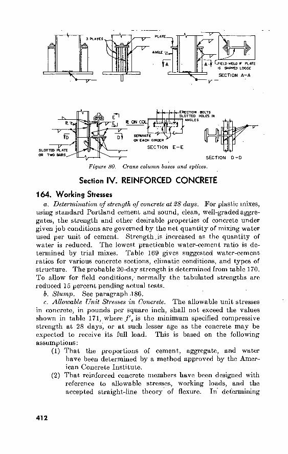
3 PLATES THV- "TT"
fr 7}^
frt IELD WELD IF PLATE
IS SHIPPED LOOSE
SECTION A-A
rArn
a 23
£ ON COL fv
ÍD SERWATE ' ON EACH GIRDER
ERECTION .BOLTS SLOTTED HOLES IN
ANGLES
H “T-
SLOTTED PLATE OR TWO BARS
SECTION E-E L^JHJ
SECTION D-D
Figure 80. Crane column bases and splices.
Section IV. REINFORCED CONCRETE
164. Working Stresses a. Determination of strength of concrete at 28 days. For plastic mixes,
using standard Portland cement and sound, clean, well-graded aggre- gates, the strength and other desirable properties of concrete under given job conditions are governed by the net quantity of mixing water used per unit of cement. Strengthjs increased as the quantity of water is reduced. The lowest practicable water-cement ratio is de- termined by trial mixes. Table 169 gives suggested water-cement ratios for various concrete sections, climatic conditions, and types of structure. The probable 20-day strength is determined from table 170. To allow for field conditions, normally the tabulated strengths are reduced 15 percent pending actual tests.
b. Slump. See paragraph 186. c. Allowable Unit Stresses in Concrete. The allowable unit stresses
in concrete, in pounds per square inch, shall not exceed the values shown in table 171, where/'c is the minimum specified compressive strength at 28 days, or at such lesser age as the concrete may be expected to receive its full load. This is based on the following assumptions:
(1) That the proportions of cement, aggregate, and water have been determined by a method approved by the Amer- ican Concrete Institute.
(2) That reinforced concrete members have been designed with reference to allowable stresses, working loads, and the accepted straight-line theory of flexure. In determining
412

41
3
Table 169. Waler-Ccinent Ratios
Type or location of structure
Severe or modérale climate, wide range of temperature, ram, and long freezing spells* or frequent freezing and thawing
(Gaiious/sack *)
Thin sections
Moderate sections
Mass sections
Mild climate, rain, or scmiarld; rarely snow or frost
(Gallons/sack *)
Thin sections
Moderate sections
Mass sections
B.
C.
A. At the waterline in hydraulic or waterfront structures or portions of such structures where complete saturation or intermittent saturation is possible, but not where the structure is continuously submerged in water
Portions of hydraulic or waterfront structures some dis- tance from waterline, but subject to frequent wetting ' by water
Ordinary exposed structures, buildings, and portions of .bridges not coming under above groups
D. Complete continuous submergence in water E. Concrete deposited through water F. Pavement slabs directly on ground:
Wearing slabs . Base slabs
5M
5/2
6 6
w (2)
5E
6/2
7 6K 5'A
0/2 (2)
(*)
(2)
(2)
(2)
(2)
7A 7
BA
(2)
(2)
G. Special case. For concrete not exposed to the weather, such as interiors of buildings and portions of structures entirely below ground, no exposure hazard is involved and the water-cement ratio should be selected on the basis of the strength and workability requirements.
1 The figures In this table correspond to U.S. 94-pound bags. 2 These sections not practicable for the purpose intended.

Table 170. Compressive Strengths at 28 Days (for Type I Cement)
Compressive strength at 28 days (pounds per square Inch)
6,000. 5.000. 4.000. 3,300. 2,800.
Gallons per bag 1
Ratio of water to cement
Cubic feet per bag >
0. 535 . 668 . 802 . 936
1. 069
Volume of water, to absolute vol-
ume of cement
1. 12:1 1. 40:1 1. 68:1 1. 95:1 2. 23:1
Weight of wrater to weight of
cement
0. 355:1 . 444:1 .533:1 .621:1 . 710:1
1 The figures in this table correspond to U.S. 94-pound bags.
the ratio n for design purposes, the modulus of elasticity for the concrete shall be assumed as 1,000/'c and that for steel as 30,000,000 pounds per square inch; the steel shall be assumed to take all tension stresses in flexural com- putations.
d. Allowable Unit Stresses in Reinforcement.1 In general, steel for concrete reinforcement should not be stressed in excess of the follow- ing limits :
(1) Tension. 20,000 pounds per square inch for rail-steel concrete reinforcing-bars,-billet-steel -concrete reinforcing-bars of in- termediate and hard grades, axle-steel concrete reinforcing bars of intermediate and hard grades, and cold-drawn steel wire for concrete reinforcement. 18,000 pounds per square inch for billet-steel and axle-steel concrete reinforcing bars of structural grade.
(2) Tension in one-way slabs of not more than 12-foot span. For the main reinforcement, Vs inch or less in diameter, 50 per- cent of the minimum yield point specified in A.S.T.M. specifications for the particular kind and grade of reinforce- ment used, but in no case to exceed 30,000 pounds per square inch.
(3) Compression, vertical-column reinforcement. Forty percent of the minimum yield point specified in A.S.T.M. specifi- cations for the particular kind and grade of reinforcement used, but in no case to exceed 30,000 pounds per square inch. For structural-steel sections, 16,000 pounds per square
i Data extracted from Journal of the American Concrete Institute, May 1956. Reprinted by permission of A.C.I.
414

533506
Description
C5 O
to -vt
Flexure: fe
Extreme fiber stress in compression, _ Extreme fiber stress in tension in
plain concrete footings. Shear: v (as a measure of diagonal ten-
sion): Beams with no web reinforcement... Beams with longitudinal bars and
with either stirrups or properly located bent bars.
Beams with longitudinal bars and a combination of stirrups and bent bars, the latter bent up suitably to carry at least 0.04 f'c
Footings 1 Bond: u
Deformed bars: 2
Top bars 3 In 2-way footings (except top
bars). All others
fc ft
V
Vc
U
u
u
» Ul
See footnotes at end of table.
Table 171. Allowable Unit Stresses
For any strength of concrete deter- mined by stand-
ard methods
_ 30,000
Maximum ealue
(pounds per square inch)
/(=2,000 pounds per square inch;
71 = 15
0.45 fc
0.03/c 900
60
0.03/; 0.08/;
0.12/;
90 240
360
60 160
240
0.03/; 75 60
0.07/; 0.08/;
245 280
140 160
o.io/; 350 200
For strength of concrete shown below
/e=2,500 pounds per square inch;
71 = 12
/e =3.000 pounds per-
square inch; 71 = 10
/e=3,750 pounds per square inch;
71 = 8
/c = 5,000 pounds per square inch;
71 = 6
125 75
75 200
300
75
175 200
250
1, 350 90
90 240
360
75
210 240
300
1, 688 113
90 240
360
75
245 280
350
2, 250 150
90 240
360
75
245 280
350

41
6
TïfV.’ . t -v j"1 2 »itv
Table 171. Allowable Unit Stresses—Continued
Description
For any strength of concrete clctcr- mined by stand-
ard methods
30,000
Maximum value
(pounds per square inch)
For strength ol concrete shown below
/c=2,000 pounds per square inch;
71 — 15
/c =2,500 pounds per square inch;
71 = 12
/e=3,000 pounds per square inch;
71 = 10
/c=3,750 pounds per square inch;
71 = 8
/. =5,000 pounds per square inch;
71 = 6
Plain bars4 (must be hooked): Top bars3 In 2-way footings (except top
bars). All others
Bearing: fc
On full area On one-third area or less 5
0.03 fc- 0.036 f'c
0.045/Ó--.
0.25/c.
0.375/;
105 126
158
00 72
90
500 750
75 90
113
025 938
90 108
135
750 1, 125
105 126
158
938 1, 405
105 126
158
1, 250 1, 875
1 Plain bars in footing slabs must be anchored by means of standard hooks. The center faces of these hooks, and the ends of deformed bars, must be not less than 3 inches nor more than 0 inches from the face of tiie footing. In isolated footings the shearing unit stress on the critical section shall not exceed 0.03 nor in any case shall it exceed 75 pounds per square inch. The critical section for shear to be used as a meas- ure of diagonal tension shall be assumed as a vertical section obtained by passing a scries of vertical planes through the footing, each of which is parallel to a corresponding face of the column, pedestal, or wall, and located a distance therefrom equal to the depth d for footings on soil, and one-half the depth d for footings on piles.
2 A deformed bar is a reinforcing bar conforming to A.S.T.M. specifications A305. "Wirc mesh with welded intersections not farther apart than 6 Inches in the direction of the principal reinforcement, and with cross wires not smaller than No. 10 A. S. & W. gage, may be rated as a deformed bar.
3 Top bars, in reference to bond, are horizontal bars so placed that not more than 12 inches of concrete is cast in the member below the bar.
4 Reinforcement which does not conform to the definition of a deformed bar shall be classed as a plain bar.
3 This increase shall be permitted only when the least distance between the edges of the loaded and unloaded areas is a minimum of H of the parallel side dimension of the loaded area. The allowable bearing stress on a reasonable concentric area greater than % but less than the full area shall be Interpolated between the values given.
Data extracted from Journal of the American Concrete Institute, May 1050. Re- prints by permission of American Concrete Institute.

inch. For cast-iron sections, 10,000 pounds per square inch. For steel-pipe columns filled with concrete, the allowable load is determined by the formula—
P=0.25/'c ^1-0.000025 ^Ac+f\As
Where P=allowable loads, lbs. y/
(.=comprcssivo strength of concrete at 28 days unless otherwise specified, psi.
A=unsupported length of column, in. , P'c=radius of gyration of concrete in pipe column.
Ac=net area of concrete section, sq. in. ^4S=effective cross-sectional area of reinforcement in
compression in column, sq. in. f'T is given by the formula—
A2
/',= 17,000—0.485
when the pipe has a yield strength of at least 33,000 pounds per square inch and an h/Ks ratio not exceeding 120; K3
being the radius of gyration of the steel-pipe section. (4) Compression, flexural members. To approximate the effect of
creep, the stress in compression reinforcement resisting bend- ing maj7 be taken at twice the value indicated by using the straight-line relation between stress and strain, and the modular ratio given in 164c(2) above, but not of greater value than the allowable stress in tension.
e. Values jor n. n, the ratio of the modulus of elasticity of steel to that of concrete, may be taken as 30,000 divided by the ultimate compressive strength of a given concrete at 28 days.
165. Weights, Areas, and Spacing oí Reinforcing Bars
a. Weights and areas of plain steel bars are given in paragraph 150. b. The designations, unit weights, and nominal dimensions of
A.S.T.M. standard deformed reinforcing bars are given in table 172. c. Table 173 shows the areas and perimeters of various combina-
tions of four bars, using the nomenclature and dimensions of table 172.
417

Table 172. A:S.T.M. Standard Deformed Reinforcing Bars
Bar designation number *
22..
3.. . 4.. .
5- .. 6- ..
7 8 9 3.. 10 3_
113_
Unit weight (pounds per
foot)
0. 167 . 376 . 668
1. 043 1. 502 2. 044 2. 670 3. 400 4. 303 5. 313
Nominal dimensions
Diameter (inches)
0. 250 . 375 . 500 . 625 . 750 . 875
1. 000 1. 128 1. 270 1. 410.
Cross-sectional area (square
.inches)
0. 05 . 11 . 20 . 31 .44 . 60 . 79
1. 00 1. 27 1. 56
Perimeter (inches)
0. 786 1. 178 1. 571 1. 963 2. 356 2. 749 3. 142 3. 544 3. 990 4,430
i Bar numbers are based on the number of eighths of an Inch included in the nominal diameter of the bars. The nominal diameter of a deformed bar is equivalent to the diameter of a plain bar having the same weight per foot as the deformed bar.
J M-inch bar in plain round only. 3 Bars of designations numbers 9, 10, and 11 correspond to the former 1-inch-square, 1 ^-inch-square, and
114-inch-square sizes and are equivalent to those former standard-bar sizes In weight and~nominal cross- sectional areas.
The above table including the footnotes is reprinted from “Tentative Specifications for Billet-Steel Bars for Concrete Reinforcement, A.S.T.M. Designation A15-58T,” revision of February 1959 by permission of the American Society for Testing Materials, and is in agreement with U.S. Department of Commerce Simplified Practice Recommendation 26-50 covering Steel Reinforcing Bars.
' Table 173. Bar Areas and Perimeters
Area (square inches)
0.79. 0.90. 1.01.
1.12.
1.23. 1.36. 1.50. 1.52.
1.63. 1.77. 1.82.
1.93. 2.09. 2.11.
2.11.
2.25. 2.32.
2.40. 2.45. 2.59. 2.77. 2.80-
Perimeter (inches)
6. 3 6. 7 7. 1 7. 5 7. 8 8: 2 8. 6 8. 6 9. 0 9. 4 9. 4 9. 8
10. 2 10. 2 10. 2 10. 6 11. 1 11. 0 11. 0 11. 4 11. 8 11. 8
A.S.T.M. bar designations
418

Table 173. Bar Areas and Perimeters—Continued
Area (square inches)
2.80. 2.88. 2.96. 3.07. 3.14. 3.20. 3.37. 3.44. 3.58. 3.60. 3.64. 3.74. 3.79. 3.93. 4.00. 4.12. 4.27. 4.41. 4.56. 4.60. 4.64. 4.70. 4.81. 5.08. 5.12. 5.37. 5.47. 5.66. 5.95. 6.24.
Perimeter (inches)
11. 8 11. 8 12. 2 12. 2 12. 6 12. 6 13. 0 13. 0 13. 4 13. 4 13. 4 13. 5 13. 8 13. 9 14. 2 14. 3 14. 6 14. 8 15. 1 15. 1 15. 1 15. 1 15. 5 16. 0 15. 9 16. 4 16. 4 16. 8 17. 3 17. 7
A.S.T.M. bar designations
d. Minimum Spacings and Clearances jor Beam Reinjorcing Bars. These are shown in figure 81. The horizontal distances AB and CD between reinforcing bars are either 1 inch, l}i times maximum aggre- gate size, or 1-bar diameter, whichever is largest.
e. Concrete Protection jor Reinforcement. The following are the provisions of the ACI Building Code on this subject:1
(1) The reinforcement of footings and other principal structural members in which the concrete is deposited against the ground shall have not less than 3 inches of concrete between it and the ground contact surface. If concrete surfaces after removal of the forms arc to be exposed to the weather
1 Quoted from pars. 50G and 1303 of “Building Code Requirements for Reinforced Concrete” adopted as a standard by the American Concrete Institute in 1956.
419

h l" MIN. CLEARANCE
A B C D
^2 X BAR DIAM. MIN.
Figure 81. Minimum spacings and clearances for beam reinforcing bars.
or be in contact with the ground, the reinforcement shall be protected by not less than 2 inches of concrete for bars larger than #5 and 1% inches for #5 bars or smaller.
(2) The concrete protective covering for reinforcement at sur- faces not exposed directly to the ground or weather shall be not less than % inch for slabs and walls; and not less than 1% inches for beams, girders, and columns. In con- crete joist floors in which the clear distance between joists is not more than 30 inches, the protection of reinforcement shall be at least % inch.
(3) If the general code of which this code forms a part specifies, as fire protective covering of the reinforcement, thicknesses of concrete greater than those given (herein), then such greater thicknesses shall be used.
(4) Concrete protection for reinforcement shall in all cases be at least equal to the diameter of bars.
(5) Exposed reinforcing bars intended for bonding with future extensions shall be protected from corrosion by concrete or other adequate covering.
(6) (For precast concrete) : At surfaces not exposed to weather, all reinforcement shall be protected by concrete equal to the nominal diameter of bars but not less than % inch.
420

166. Standard Notation for Beam Formulas ^4s = area of reinforcing bars in square inches 6=width of rectangular beam, or of slab or T-bcam, in inches
6' = width of stem of T-beam, in inches d= depth of beam to center of tension reinforcing, in inches fc= compressive unit stress in concrete in pounds per square inch
/,c= ultimate compressive strength of 28-day concrete, in pounds per
square inch /s=Tensile stress in reinforcing in pounds per square inch
ratio of distance (jd) between resultant of compressive and tensile stresses to effective depth
k jd=arm of resisting couple; ,7=1 — » for rectangular bars
O
&=ratio of distance (kd or kt) between extreme fiber and neutral axis to effective depth or to total depth
M=depth of beam to neutral axis in inches M
coefficient of resistance beamr-r.
M~moment of resistance, or bending moment, =g WL for simple, uniformly loaded beams
n=Es/Ec: taken as 30,000
ultimate 28-day compressive strength of concrete
p = percentage of reinforcing=^
t = overall dimension of column in inches; also depth of flange
w=shearing stress in pounds per square inch = 4= for rectangular y öja
beams; for T-beams b'jd
y= Total shear in pounds z=ratio of distance (zkd) between extreme fiber and resultant of
compressive stresses to distance kd
167. Design Data for Slabs and Rectangular Beams The following data apply to rectangular beams with tension rein-
forcing, and to slabs reinforced in one direction when designed as rectangular beams 1 foot wide:
421

422
Pf?? T r n¡f mggpnpv. fr*’ >'■ * '
a. Coefficients K, k, j, pjvr rectangular beams: Table 174- Coefficients {K, k, j, p) for Rcclangular Sections
f'c and n
2000
15
2500
12
3000
10
3750
700 750 800 900
1000 1200
875 950
1000 1125 1250 1500
1050 1125 1200 1350 1500 1800
1300 1400 1500 1700 1875 2250
161 177 192 224 255 320
202 225 240 280 319 400
242 265 288 335 383 480
298 329 360 423 479 600
/.=8,00ü «=0.53
0. 568 . 584 . 600 . 628 . 652 . 693
. 568
. 588 . 600 . 628 . 652 . 693
. 568
. 584
. 600
. 628
. 652
. 693
. 565
. 583
. 600
. 630
. 652
. 693
0. 811 . 806 . 800 . 791 . 783 . 769
. 811
. 804
. 800
. 791
. 783
. 769
. 811
. 806
. 800
. 791
. 783
. 769
. 812
. 806
. 800
. 790
. 783
. 769
0. 0249
. 0274
. 0300
. 0353
. ü408
. 0520
. 0311 . 0349 . 0375 . 0442 . 0509 . 0650
. 0373
. 0411
. 0450
. 0530
. 0611
. 078Ó
. 0459
. 05l0
. 0563
. 0669
. 0764
. 0975
/.= 10,0üU a=0.U8
149 163 179 209 240 303
186 208 223 261 300 379
223 245 268 313 360 455
275 305 335 396 450 568
0. 512 . 529 .•546 . 574 . 600 . 643
. 512
. 533
. 546
. 574
. 600
. 643
. 512 . 529 . 546 . 574 . 600 . 643
. 510
. 528
. 546
. 576
. 600
. 643
0. 830 . 824 . 818 . 809 . 800 . 786
. 830
. 823
. 818
. 809
. 800
. 786
. 830
. 824
. 818
. 809
. 800
. 786
. 830
. 824
. 818
. 808
. 800
. 786
0. 0179 . 0198 . 0218 . 0258 . 03Ó0 . 0386
. 0224
. 0253
. 0273
. 0323
. 0375
. 0482
. 0269
. 0298
. 0328
. 0387
. 0450
. 0579
. 0332
. 0370
. 0410
. 0490
. 0563
. 0723
k = 1
1 +fs/nfc
j = l-¡k
V* = 2fsXIC
K-^S»
a=l2 00üX (average i'value)
f . M . NE for use m As = —. or As = —— ad adi

42
3
5000
2000
15
2500
12
3000
10
1500 1750 2000 2250 2500 3000
700 750 800 900
1000 1200
875 950
1000 1125 1250 1500
1050 1125 1200 1350 1500 1800
327 403 480 559 638 799
138 152 167 196 227 288
173 194 208 246 283 360
207 229 250 294 340 432
. 529
. 568
. 600
. 628
. 652
. 692
. 824
. 811
. 800
. 791
. 783
. 770
/* = 12,000 a=0.83
467 . 484 . 500 . 529 . 556 . 600
. 467 . 487 . 500 . 529 . 556 . 600
. 467 . 484 . 500 . 529 . 556 . 600
844 , 839 , 833 . 824 . 815 . 800
. 844
. 838 . 833 . 825 . 815 . 800
. 844
. 839
. 833
. 824
. 815
. 800
. 0496
. 0621
. 0750
. 0883
. 1019 . 1298
, 0136 . 0151 . 0167 . 0198 . 0232 . 0300
. 0170
. 0193
. 0208
. 0248
. 0290
. 0375
. 0204
. 0227
. 0250
. 0298
. 0348
. 0450
‘Balanced steel ratio” applies to problems involving bending only.
299 371 446 522 600 758
474 . 512 , 545 , 574 . 600 . 643
. 842
. 829
. 818
. 809
. 800
. 786
. 0356
. 0448
. 0545
. 0646
. 0750 . 0965
K
/»= 14,000 0=0.98 /. = 1G,000 0=1.13
129 142 156 185 214 274
161 181 195 231 268 343
193 213 235 277 321 411
, 429 . 446 . 462 . 491 . 517 . 563
. 429
. 449 . 462 . 491 . 517 . 563
. 429
. 446
. 462
. 491
. 517
. 563
857 . 851 , 846 . 836 . 828 . 812
. 857
. 850
. 846
. 836
. 828
. 812
. 857
. 851
. 846 . 836 . 828 . 812
. 0107
. 0119
. 0132
. 0158
. 0185
. 0241
. 0134
. 0152
. 0165 . 0197 . 0231 . 0302
. 0161
. 0179
. 0198
. 0237
. 0277
. 0362
120 133 147 175 203 262
150 170 184 218 254 327
180 200 221 262 305 392
396 . 413 . 429 . 458 . 484 . 529
. 396
. 416
. 429
. 458
. 484
. 529
. 396
. 413
. 429 . 458 . 484 . 529
. 868
. 862
. 857
. 847
. 839
. 824
. 868
. 861
. 857
. 847
. 839
. 824
. 868
. 862 . 857 . 847 . 839 . 824
. 0087
. 0097
. 0107
. 0129
. 0151
. 0198
. 0108
. 0124
. 0134
. 0161
. 0189
. 0248
. 0130
. 0145
. 0161
. 0193
. 0227
. 0298
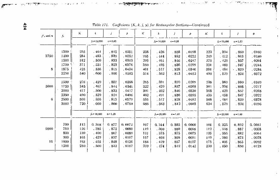
42
4
Ijvrr- » W- t
Tabic 17h. Coefficients (K, k, j, p) for Hcchuujular Sections—Continued
f'e and n
3750 1300 1400 1500 1700 1875 2250
5000 1500 1750 2000 2250 2500 3000
2000
15
700 750 800 900
1000 1200
255 284 312 371 425 540
276 345 417 490 566 720
113 126 139 165 193 250
/i = 12,000 (1=0.83
464 483 500 531 556
. 600
429 , 467 500 529 556 600
845 839 833 823 815 800
857 844 833 824 815 800
0251 0282
. 0313 , 0376 . 0434 , 0563
0268 . 0341 . 0417 , 0496 . 0579 , 0750
/»= 18,000 a=1.29
0. 368 . 385 . 400 . 429 . 455 . 500
0. 877 , 872 . 867 . 857 . 848 . 833
0. 0072 . 0080 . 0089 . 0107 . 0126 . 0167
/* = 14,000 (1=0.08
238 265 293 350 401 514
255 322 391 462 535 686
426 444 461 493 517 562
391 429
. 462 491 517
. 563
, 858 . 852 . 846 , 836 , 828 . 813
, 870 . 857 . 846 . 836 . 828 . 812
0198 0222 0247 0299 0346 0452
0209 0268 0330 0395 0462 0603
/. = 20,000 rt = 1.44
107 119 131 157 184 239
0. 344 . 360 . 375 . 403 . 429 . 474
0. 885 . 880 . 875 . 866 . 857 . 842
0. 0060 . 0068 . 0075 . 0091 . 0107 . 0142
/.=10,000 (1=1.13
223 249 276 331 381 490
238 301 368 436 508 654
394 412
. 429 460 484 529
360 , 396 , 429 , 458 484
, 529
. 869 863
, 857 . 847 839
, 824
880 , 868 . 857 847 839
. 824
/. =22,000 a=l.00
101 112 125 149 175 230
0. 323 . 338 . 353 . 380 . 405 . 450
0. 892 . 887 . 882 . 873 . 865 . 850
. 0160 , 0180 . 0201 , 0244 , 0284 . 0372
. 0169
.0217
. 0268 , 0322 , 0378 . 0496
0. 0051 . 0058 . 0064 . 0078 . 0092 . 0123
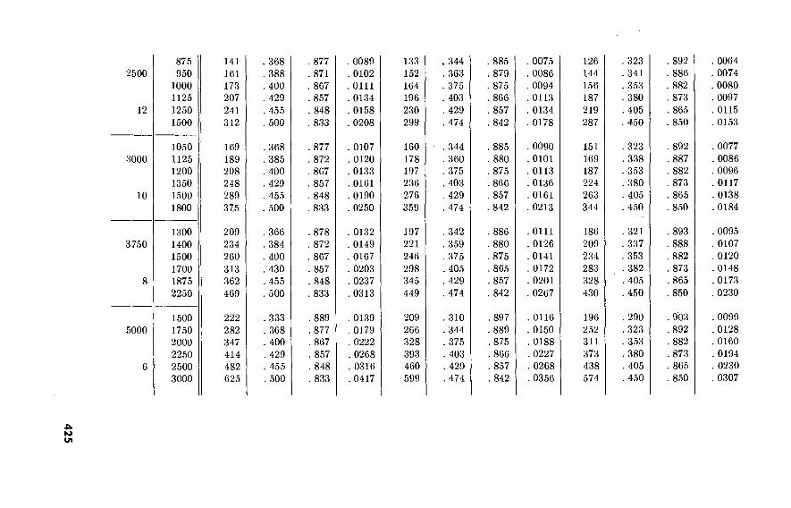
425
2500
12
875 950
1000 1125 1250 1500
3000
10
1050 1125 1200 1350 1500 1800
3750
8
1300 1400 1500 1700 1875 2250
5000
6
1500 1750 2000 2250 2500 3000
141 161 173 207 241 312
. 368
. 388
. 400
. 429
. 455
. 500
. 877
. 871
. 867
. 857
. 848
. 833
. 0089 . 0102 . 0111 . 0134 . 0158 . 0208
169 189 208 248 289 375
. 368
. 385
. 400
. 429
. 455
. 500
. 877
. 872
. 807
. 857
. 848
. 833
. 0107
. 0120
. 0133
. 0161
. 0190
. 0250
209 234 260 313 362 469
. 366
. 384
. 400 . 430 . 455 . 500
. 878
. 872
. 867 . 857 . 848 . 833
. 0132
. 0149
. 0167
. 0203
. 0237
. 0313
222
282 347 414 482 625
. 333
. 368
. 400 . 429 . 455 . 500
. 889
. 877
. 867
. 857
. 848
. 833
. 0139
. 0179
. 0222
. 0268
. 0316
. 0417
133 152 164 196 230 299
344 363 375 403 429 474
885 . 879 875 866
. 857
. 842
0075 0086 0094 0113 0134 0178
126 144 156 187 219 287
. 323
. 341 353 380
. 405 450
892 886 882 873
. 865 850
160 178 197 236 276 359
344 . 360 375 403 429 474
. 885
. 880
. 875
. 866
. 857 842
0090 0101 0113 0136 0161 0213
151 169 187 224 263 344
323 338 353 380 405 450
. 892
. 887 882
. 873
. 865 850
197 221 246 298 345 449
342 359
. 375
. 405 , 429 474
886 880 875 865 857 842
0111
0126 0141 0172 0201
0267
186 209 234 283 328 430
321 337 353 382 405 450
, 893 . 888 882
, 873 . 865 . 850
209 266 328 393 460 599
310 344 375 403
. 429 474
. 897 889
. 875
. 866
. 857
. 842
0116 0150 0188 0227 0268
. 0356
196 252 311 373 438 574
290 323 353 380
. 405 450
. 903
. 892
. 882
. 873
. 865
. 850
. 0064
. 0074
. 0080
. 0097
. 0115
. 0153
. 0077
. 0086
. 0096
. 0117
. 0138
. 0184
. 0095
. 0107
. 0120 . 0148 . 0173 . 0230
. 0099
. 0128
. 0160
. 0194
. 0230
. 0307

42
6
*'-r^ tjmr ’J T-
' * '«t ;w\ ■ jj- "• i;* -^B■ Tanfp"g~»yy
Toft/e /7^. Coefficients (K, k,j, p) for liectangvlar Seciio/is—Continued
f'c and n fc
2000
15
700 750 800 900
1000 1200
2500
12
875 950
1000 1125 1250 1500
3000
10
3750
1050 1125 1200 1350 1500 1800
1300 1400 1500 1700 1875 2250
/s=*4,000 a = 1.70
96 107 118 143 168 220
120 137 148 178 210 270
143 160 178 214 252 331
176 199 222 270 315 414
304 319
, 333 360 385 429
. 304
. 322
. 333
. 360
. 385
. 429
. 304 , 319 . 333 . 360 . 385 . 429
, 302 . 318 . 333 , 362 . 385 , 429
899 894
. 889 880 872 857
899 893 889
. 880
. 872
. 857
. 899 894
. 889
. 880
. 872
. 857
, 899 . 894 , 889 , 879 . 872 . 857
0044 0050 0055 00Ö7 0080 0107
0055 0064 0069 0084 0100 0134
0067 0075 0083 0101 0120 0161
0082 0093 0104 0128 0150 0201
/s=27,000 o='2.0U
89 99
111 133 157 208
111 127 138 167 197 260
133 149 166 200 236 312
164 185 207 253 295 390
280 294 308 333 357 400
. 280 297
. 308 333
. 357
. 400
. 280 294
. 308 333
. 357 400
, 278 . 293 . 308 . 335 . 357 . 400
907 902 897 889 881 867
907 90 J
. 897 889 881 867
. 907 902 897 889 881 867
907 . 902 . 897 888
. 881 867
0036 0041 0046 0055 0066
. 0089
0045 0052
. 0057 0069
. 0083
. 0111
. 0054 0061
. 0068 0083
. 0099 0133
. 0067
. 0076 , 0086 . 0106 , 0124 . 0166
/8=30,«00 a=2.24
83 93
104 125 148 197
104 119 129 156 185 246
124 140 155 188 222 295
153 173 194 238 278 369
259 273 286 310 333 375
259 275 286 310 333 375
259 273 286 310 333 375
257 272 286 312 333 375
914 909 905 897 889 875
914 908 905 897 889 875
914 909 905 897 889 875
914 909 905 896 889 875
, 0030 0034
, 0038 0047
. 0055
. 0075
. 0038 0044
. 0048
. 0058 , 0069 0094
, 0045 0051 0057 0070 0083 0113
0056 0063 0071 0088 0104 0141

427
5000
1500 1750 2000 2250 2500 3000
186 239 296 356 420 551
273 304 333 360 385 429
. 909 899 889 880 872 857
. 0085 . 0111 . 0139 . 0169 . 0201 . 0268
172 222
276 333 393 520
. 250
. 280
. 308
. 333
. 357
. 400
917 907 897 889 881 867
. 0069
. 0091
. 0114
. 0139 . 0165 . 0222
160 207 259 313 370 492
231 259 286 310 333 375
. 923
. 914
. 905
. 897
. 889
. 875
. 0058
. 0076
. 0095
. 0116
. 0139
. 0188

I*.
I
I
s- r E
6. Formulas. For beams beyond the scope of table 174, the follow- ing formulas are used :
(1)¿= nfc nfc+fs
or pfs 1/2/«
w=fé°'ú
(3)/=i-|;/d=d-y
(4) F:=/Spj or g; d= IM bk
,-S A M {0) As~fjd
168. Design Data for T-Beams The following data apply to T-beams with adequate web reinforce-
ment, normally provided by bending about one-half of the longi- tudinal bars and providing stirrups if required.
a. Determination of Width b. For T-beams or L-beams, the width b may not exceed one-fourth the span length of the beam; and the effective width overhanging on either side of the stem may not exceed one-half the clear distance to the next beam or eight times the slab thickness.
b. Formulas. For beams beyond the scope of table 175, the follow- ing formulas are used :
(1)* 1+4 nfc
kd 2ndAs-\-bt2
2nA,+2bt
(2) jd=d—z; ?>kd—2t..t 2=2B=rx3
(3)
c. Design Constants. For n=\0 and îI=15, and for various values of fs, fc, and t/d, values of k and p are given in table 175. Interpola- tions are made for other values of n, fs, and fe.
169. Design of Beam Stirrups 1 * *
a. Aera of Steel. The fundamental equation for stirrups is—
A V's
° Bfjd 1 Material in this paragraph is taken, with minor changes in wording, from pp. 22 and 23; formula 30 on
p. 96; table 9 on p. 52; diagram 17 on p. 58; and table 15 on p. 57, of the ACI Reinforced Concrete Design Handbook, second edition, 1955.
428

where—
A„—total cross-sectional area of stirrup legs V—v'l>jd=total shear to bo carried by stirrups _B= (sin x cos x) with x = angle between stirrups and axis of beam.
From this—
. v'bs 1 v'b °r STBA,f,
For sthrups perpendicular to the axis of the beam, B=l, and the last equation becomes—
1 v'b S~ÄJV
In a rectangular beam or in the stem of a T-beam, the concrete alone is assigned to carry shear up to 3 percent of its 28-day ultimate com- pressive strength.
b. Number and Spacing. The determination of the number and spacing of stirrups depends on the shape and area of that part of the shear diagram for which sthrups are required. The area of the shear diagram determines the number of stirrups required, while the stirrup spacing depends also on the shape of the diagram. Shear diagrams may be considered of three types—rectangular, trapezoidal, and tri- angular. Only trapezoidal and triangular shear diagrams offer prob- lems in sthrup spacing, because the spacing is constant for rectangular diagrams. The procedure is as follows:
(1)
(2)
(3) (4)
(5)
Select the type of stirrup (vertical or inclined) ; the total area of sthrup legs Av (a above)) ; and the allowable steel stress
v* b Calculate the value ^ at the large and small ends of the
shear diagram and at points of discontinuity. To obtain the value of use figure 82(1). Calculate S, the length of the base of the shear diagram. Determine the number and spacing of the stirrups. To do
b this, superpose the ß^ j curve on figure 82(2). Read the
sthrup spacing where the curve crosses the heavy vertical lines. The number of stirrups requhed equals the number of vertical lines intersected. Check by figure 82(3) for embedment of sthrups.
429

43
0
f*"*' nir*
1'able 175. Design Constants, T-Beams
16, 000
18, 000
K=15
t/d
0. 06 . 10 . 14 . 18 . 22 . 26 . 30 . 34 . 38
/c=600
K
32 50 64 76 84 89 93 95
, 06 , 10 , 14 , 18 22
26 30 34 38
32 49 62 73 80 85 88
06 10
32 48
0. 0021 . 0032 . 0042 . 0051 . 0057 . 0062 . 0066 . 0067
. 0018
. 0028
. 0037
. 0044
. 0049
. 0053
. 0055
. 0016
. 0025
/e=700
K
38 58 76 90
100 109 115 118 120
38 58 74 88 98
105 110 113
37 57
0. 0024 . 0038 . 0051 . 0061 . 0070 . 0076 . 0082 . 0085 . 0087
. 0021
. 0034
. 0044
. 0053
. 0060 , 0066 . 0069 0071
0019 0030
/e=800
43 67 88
104 118 129 137 142 146
43 67 86
102 115 125 132 136 138
43 66
0. 0028 . 0044 . 0059 . 0071 . 0082 .0090 . 0098 . 0102 . 0106
. 0025
. 0039
. 0051
. 0062
. 0071
. 0078 , 00831
. 0087 0089
0022
0035
/c=900
K
49 76
100 120 136 149 159 166 171
49 76 99
117 133 145 154 160 164
49 75
0. 0032 . 0050 . 0067 . 0081 . 0094 . 0105 . 0113 . 0120
. 0125
. 0028 0044 0059 0071 0082 0091 0097 0103 0106
0025 0039
»=10
/c=750
K
40 60 77 89 98
104 107
39 60.
75 87 95 98'
39 58
0. 0025 . 0040 . 0051 . 0061 . 0068 . 0072 . 0074
. 0022
. 0035
. 0045
. 0052
. 0057
. 0060
. 0020
. 0031
/i=900
K
48 75 96
114 126 134 140 142
48 73 93
109 120 128 132
48 72
0. 0032 . 0049 . 0063 . 0076 . 0085 . 0093 . 0098 . 0101
. 0027
. 0043
. 0055
. 0066
. 0074
. 0079
. 0082
. 0024
. 0038
/e=1200
K
65 100 132 156 177 194 206 213 219
65 100 130 154 173 188 198 205 207
64 99
0. 0042 . 0066 . 0088 . 0107 . 0122
. 0134
. 0145
. 0153
. 0158
. 0037
. 0058
. 0077
. 0093
. 0106 , 0117 . 0125 , 0130 0133
0033 0052
/e=1350
K
73 114 150 180 204 224 238 249 256
73 1.13 148 176 199 218 231 241 246
73 113
0. 0047 . 0075 . 0099 . 0122
. 0140
. 0156
. 0169
. 0180
. 0187
, 0042 . 0066 . 0088 . 0107 , 0123 0136 0146 0154 0159
0038 0059

533506
20, 000 14 18 22 26 30 34 38
61 71 78 82 84
. 0033
. 0038
. 0043
. 0045 0046
73 86 95
102 106 107
0039 0047 0052 0057 0059 0060
85 101 113 121 128 •130-
.0046
. 0055
. 0062 , 0068 , 0072 . 0074
97 116 130 141 149 154 156
. 0052
. 0Ó63
. 0072
. 0079
. 0085
. 0088
. 0090
73' 84 90' 93
. 0039
. 0045
. 0049
. 0051
■ 92 106 117 123 126
. 0049
. 0057
. 0064 . 0068 . 0070
128 ' 151 169 182 192 196
0068 ■
0082. 0093 01Ö2 0108 0112
146 174 195 211 224 231 234
(Reprinted from Manual of Structural Design by Singleton by permission of H. M. Ives & Sons. Copyright 1947.)
4b M
. 0078
. 0095
. 0108
. 0119
. 0127
. 0133
. 0135

432
2t k Zd t
Values of; - 1 X - and y - 2k - -
d
1 - 2t
Zkd
-B (a) Enter tabla with known value of ^ and k\ select j.
(b) Enter table with known value ofselect y; compute ; - 1 — y^'
3 cofa
n.A. f
0.20 0.29 0.30 0.35 0.40 0.45 0.60 0.55 0.60
0.06 0.06
0.97] 0.97 0.97 0.97 0.97 0.97 0.97 0.97 0.97
0.961 0.96 0.96 0.96 0.96 0.96 0.96
■0.96 0.96
0.10
0.961 0.95 0.95 0.95 0.95 0.95 0.95 0.95 0.95
o.i2| 0.14) o.iej o.iej o.2oj 0.22
0.95 0.95 0.94 0.94 0.94 0.94 0.94 0.94 0.94
0794] 0.94 0.94 0.94 0.93 0.93 0.93 0.93 0.93
0.941 0.93 0.93 0.93 0.93 0.93 0.93 0.92 0.92
0.93 0.93 0.92 0.92 0.92 0.92 0.92 0.92 0.92
0.931 0.9? 0.92 0.91 0.91 0.91 0.91 0.91 0.91
0.92 0.91 0.91 0.90 0.90 0.90 0.90 0.90
0.24 0.26
0.92 0.91 0.90 0.90 0.89 0.89 0.89 0.89
0.90 0.90 0.89 0.89 0.89 0.88 0.881
0.28j 0.30| 0.32) 0.34| 0.36) 0.38
0.90 0.89 0.89 0.88 0.88 0.88 0.87
0.88 0.89 0.8 0. 87 0,
0.87 0. 0.86 0.8 0.85 0.8 0.85 0.8 0.8
0.87 0.86 0.85 0.85 0.85
0.87 0.86 0.85 0.84 0.84
0.40
0.87 0.85 0.84 0.84 0.83
kd 0.15 0.20 ).25j 0.3oj O.Ssj Q.4o| OMsj O^SO 0.5sj 0.60| 0.65|
0.49j 0.48| 0.48] 0.47¡ 0.46| 0.46| 0.45| 0.44
0.70 0.75 0.80 0.85 0
0,44| 0.43) 0.42j 0.41
.9o| O.Osj 1.00
o.4Q| o.39| o.38j o.36| o.as^aja^
Figure 82(1). Coefficients for T-sections.
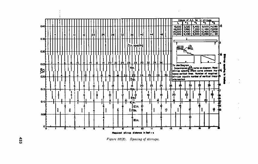
433
0.40-
033-
OJC -
QIS
025-
§3 020 -
20 24
I K)
rm
28
20
AU 22
¥
24
3iiv spocinq
26
m
40
28
f 6ja-
30 32
24
20 22
30
»
VOluM Ol fl-t. (.
16,000 18,000 20JOOO 24 JOPO
3,320 3,960 4,400 5,280
tor U-sürruoi
6,400 7,200 8,000 9,600
9^920 11,160 12,400 14,880
14,080 1^840 17,600 21,120
To UMOiogrom . SupoiiinBongyfrcun)» on <
sllrrup «podng < heavy vertical linee. Number of required stirrups equals number of vertical lines- intersected.
26 28 30 32 \
aio ::
I i ace -
“I—On. 112 in. »
I ISIn. 11
I 20 4
2) 4
10
Oh.
o . 7 8 9 K) II 12
Required stirrup distance In feet • s
Figure 82(2). Spacing of stirrups.
****
**
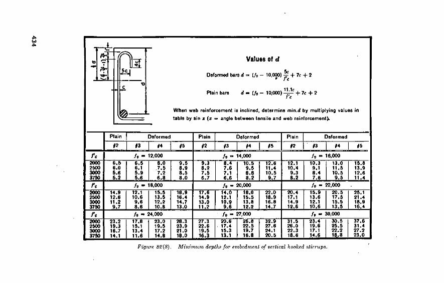
434
¿ «T fl Values of d
Deformed bars d = (/s - 10,000) ~ + 7c +2 * J c
Plain bars d- (h- 10,000) ^-C + 7c + 2
When web reinforcement is inclined, determine min.d by multiplying values in
table by sin x (z = angle between tensile and web reinforcement).
Plain Deformed Plain Deformed Plain Deformed
#2 #3 #5 #2 f3
re 2000 2500 3000 3750
/r 6.5 6.0 5.6 5.2
6.5 6.1 5.9 5.6
ft it 2000 2500 3000 3750
14.9 12.6 11.2 9.7
12.1 10.6 9.6 8.6
it
2000 2500 3000
23.2 19.3 16.7
1
it 17.8 15.1 13.4 11.6
12,000
8.0 7.5 7.2
9.5 8.9 8.5
ft 9.3 8.2 7.6
8.4 7.6 7.1
6.8 8.0 6.7 6.6 18,000 ft
15.5 13.5 12.2 10.8
18.9 16.4 14.7 13.0
17.6 14.9 13.0 11.2
14.0 12.1 10.9 9.6
24,000
23.0 19.5 17.2 14.8
28.3 23.9 21.0 18.0
ft 27.3 20.6 22.6 19.5 16.3
17.4 15.3 13.1
14,000
10.5 9.5 8.8
12.6 11.4 10.5
ft 12.1 10.3 10.4 9.1 9.3 8.4
8.2 9.7 8.2 7.6
20,000 ft TfÛT 15.5 13.8 12.2
22.0 18.9 16.8 14.7
20.4 17.1 14.9 12.6
15.9 13.6 12.1 10.6
27,000 ft 26.8 22.5 19.7 16.8
32.9 27.6 24.1 20.5
31.5 26.0 22.3 18.6
23.4 19.6 17.1 14.6
16,000
13.0 11.5 10.5 9.5
22,000
20.5 17.5 15.5 13.5
30,000
30.5 25.5 22.2 18.8
<5
15.8 13.9 12.6 11.4
25.1 21.4 18.9 16.4
37.6 31.4 27.2 23.0
Figure 82(8). Minimum depths for embedment of vertical hooked stirrups.

170. Example oí Slab or Rectangular-Beam Design a. Problem. What slab depth and reinforcing are needed for a
span of 10 feet, live load of 500 pounds per square foot, using 2,000 pound concrete and Bessemer steel reinforcing good for 18,000 pounds per square inch?
b. Solution. (1) 71=30,000^-2000=15 (par. 164e) (2) /„=2000X0.45 = 900 psi (par. 164c) (3) 5 = 12 inches (section of slab 1 foot wide) (4) Assume 8-inch slab thickness (normally 0.8 inch per foot of
span) (5) Total load=500 +(^2X150) =600 pounds per square foot (6) •M=y& Wl=% (600X10) (1OX12) = 9O,O0O inch-pounds (7) - 2?= 165.3; .7=0.857; p=0.0107 (par. 1675)
, ¡M I 90,000 „ ^ o • u (8) . ¿= Vta=Vl2XÍ65.3=6-7; USe 8 1Dches
(9) Aa=p5c(=0.0107X12X6.7 = 0.86 square inch. Adopt #6 bars spaced 6 inches c.-to-c., area=0.88 square inches per foot of width.
c. Example {Vertical Stirrups, Triangular Shear Diagram).
(scale marks are 1-mm each)
Given : Max. «'=108 psi;
/S'=8 ft. 3 in.; 5=13 in.; <?^=20 in.; /„= 20,000 psi; /'c=3,000 psi;
No. 3 U-stirrups.
From figure 82-B, for/„=20,000 and No. 3 U-stirrups: Ac/r=4,400; and JB=1 for vertical stirrups.
v'b BÄJ,
108X13 4,400 0.319.
On figure 82-B, place a straightedge connecting the values of S and v'b = and read the spacing of stirrups where their respective heavy
v
lines cross the straightedge. In case the spacing is greater than the maximum allowable spacing of %d, use the last spacing permitted until distance S is reached. Read: 3 at 3 in., 5 at 4 in., 2 at 5 in., 2 at 6 in., 1 at 8 in., 4 at 10 in. Total number of stirrups: N=17. Refer to figure 82(3) for No. 3 stirrups with /'c= 3,000 psi and /„= 20,000 psi and ascertain that stirrups have sufficient embedment;
435

d~ 10.9 in. required. If it is desired to locate the first stirrup at half v^b
the initial spacing from the end of beam, the p . , curve should be Jj-ixVJ c
shifted horizontally a distance equal to half the initial stirrup spacing. d. Inclined Stirrups. They are proportioned by the formula —
' fvjd (sin a + cos a)
Where a=angle between stirrups and axis of beam. e. Limitation. Stirrups placed perpendicular to the longitudinal
reinforcement must not be used alone as web reinforcement when the shearing unit stress (w) exceeds 0.08/'e or 240 pounds per square inch.
1 71. Example oí T-Beam Design a. Problem. Design a T-beam for a clear span of 20 feet, slab
thickness of 5 inches; total load from slab 400 pounds per square foot, beam spacing 9 feet center to center, 3,000-pound concrete, allowable stress in steel 20,000 pounds per square inch.
b. Solution. (1) ?z = 30,000-HS,000= 10 (par. 164e) (2) _/c=3,000X0.45 = 1,350 psi (par. 164c) (3) 6 = 60 inches span length controls (par. 168a) (4) Assume 6' = 15 inches (trial and error) (5) Assume (Z=13 inches (trial and error)
(6) iré--38
(7) i£=234; p = 0.0135 (par. 168c)
(8) Weight of stem = ^j^^X 150= 188 pounds per foot
(9) Total load = 9X400 +188 = 3,788 pounds per foot (10) TT/A=KX3,788X20X20X12 = 2,272,800 inch-pounds
. . , IM /2,272,800 . , (11) d=ÍbK=-\ 60X234 =12-7 inches
(12) As=p6d=0.0135X60X12.7 = 10.2 square inches. Adopt four #11 square bars and four #9 square bars: total area 10.24 square inches (par. 1656).
(13) Eequired 6, = 13Xl)í=16)í inches. Adopt 16 inches (re- quired for four 1 ((-inch bars in one layer, figure 81)
(14) Total depth of stem below slab=13M + K + ^+(2Xl)i)—5 = \2)i inches. Adopt 12 inches.
(15) Design of stirrups— (a) Revised weight—
Load from slab—400 psfX9 ft = 3,600 lbs. 12 v 1 fi
Stem below slab ——X150= 200 lbs. 1 4 3,800 lbs/ft
436

(b) y=KX3,800X20 = 38,000 lbs.
<e>'=íx7x3- 6-16" "=13"- 1. tld=0.38
2. K=
nAs
bt ■\\yjtld
nAs
bt 1
10X10.24 1 60X5 +2XU-38
10X10.24 60X5
0.398
8. With t/d=0.38 and £=0.398, enter figure 82(1) and determine .7 = 0.87 = 210 pounds per square inch.
(d) Then v 38,000
16X0.87X13 (e) (/) (g)
(h)
»„=0.03X3,000 = 90 psi «' = 210 — 90=120 psi From figure 82(2) for /„= 20,000 psi and #3 U-stirrups, -d-r/ti=4,400 and B=l for vertical stirrups, then —
v'b 120X16 BAJ, 1X4,400
120X10 S 210
5.71'
0.436
(i) Enter figure 82-B for— v* b
.=0.436 along left side and 5= 5.71' along the bottom, BAFJC
choose stirrups as follows-— 8 at 3", 2 at 4", 2 at 5", 5 at 6". (This carries the stirrups past the point where they are required. It should be noted here that, according to figure 82(2), we could have used 8", 9", and 10" spacing, but we are limited to %d as a maximum.)
172. Retaining Walls For average earth pressures and for heights up to 10 feet, cross
sections of plain concrete and reinforced concrete are given in figure 83.
Section V. TIMBER
1 73. Working Stresses Table 176 shows the allowable unit stresses for stress-grade lumber
of certain species and grades. The figures are for normal loading condi tons and for peacetime civilian or equivalent military con- struction. For temporary structures, and for military construction in a theater of operations, the stresses given in the table may be increased by a maximum of 50 percent.
437
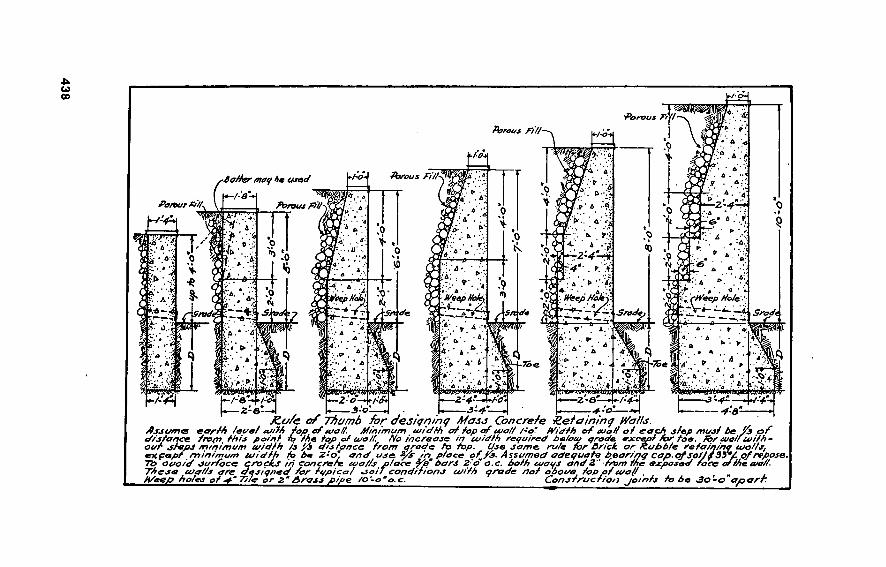
438
"Porous F/
Porous Fifí
. A . i»
A * A Porous Ft// /•o+ So/rer mat/ 4e osea .-Ÿ
&
Porous Ft//\<JL
. 0 '.* /Ö- a . * .
Pomas Ft// . _ ^
A -A ¡F?
t « A
- ,4 :> -f-H A .
. A *
J." 4. 4
fc-.’;: J .. A » .• • A N ;
^ %
r’ . A .*f. • * . A * *
r>f<Pe/p Fo/s'.';
Sradt
■ •. ' FoepMoitj
.40* A.'..« H/eepHoki MfepFoky.
•^zé .«• .Al!
ÍPI S rodo Sn d-e Stt do radi
«v 5 A • » . V 3 \ ■ A,
0- . >'* \ ZK*- •m ► >, A s "jm
A* A 73 e • A;: ? . à .. A ■
Sill !^|
^ii
?. A >:• • /» - A .
1 wn ■Hr;-*' * ». -s * ? 6.^ .>■0 VA,... V,A SÍftíflÍDÍ^Apí tí^jP
/->- ^/->- ^/-a -*./-«»
-—¿-a-—
2-0 2-4- j-o 2-a 4“ /-o*
3-4 3-0 — 4-a- JZc//e of Thumb for desi<jninç Mass Concrete tletaininq Walls.
Asjome eartf> /eye/ a/M fop ef toa//. Minimum toidth at top at usa// l-o". Width at Mali at er c//sfance fro/n /his point to /he /op of cua/f. No increase in coid/h required óe/otu qrode axce¿ oat dfepJ /ntni/nam widfh is ft distance from qrade to fop. Use some ru/e for ßrick. or ft .... r_, exçepf minimum loid/h fo be 2-o' and use ^/s" inm piace of ft. Assumed adequate b^arinç cop.qf SofJf3o°/. of repose. To oao/d surface crachas in concrete tcto//sa/ace j/e“ bars 2:d o.c. both cueys and Z" from the exposed face of /he wa/i. These u/afis are designed for it/picoi *soi/ conditions cai/h qrade not o&oue top of ura/i , . Jifeep ho/es of *+* 77/e or 2m &rass pipe /O~o"o.c. Consrrucrioti jotnts robe So -o apart.

•KE sor-
- Aneo ñhff •mum
1 ''A
.9-«
I ^ ^éfm. width
1 1 I 1
For’ this dimension i
1 joe sheet *7
I 2 355^535 o
S5
I» • i Rods 2 '-o'O.C. hath ways - t'» ' present expansion cracks.
f>ton .CONSTRUCTION
JOUST
t/iqh Çrode.-
Ro/nforced tdaffs arc usuatlq more económica/ than mass saa/ts.
%ü;::%9*£X™
"ir Ÿat/s snoum are. /or areas not ever tí'o" tona,-ter each add/t-m . . a. ¡one/ p'o'in Zenith up to lo'-o increase u/att /, if over /O’O" tonq broce areas a/ith cross tualls.
AR-EA WAL.L.5.
tti<jh Srade
^IKr
Çt/iÿh Çrade
!«
Zia, S3
bars fZ'o.c.
U/eep //oies /ata
w- •4 Z\ 6
Hiqh Grade $ '<f‘d bars /t "<yc
'/bars Æa.c
*/o t bars VS*o.c.~
¿/sed /or /at Une a/of/s
U TYPE.
fr
' ’T
¿otoÇrèdi
„•t
r2-' 7£4 bars /¡t
SÜ3L#
5 —
; yd bars JQ/í*O C
■porous Fi//
Porous ft/f
Weep Holes
2-/0' Í //
j, . S i‘èarj /Ha /•» ^ i ^ r
' T? r ' '¡^S'/ÂdJ \ v*'*», -
Weep //o/e ¿oo/ Crade-r^i J
. ni dbars /¿'o-c i
E.
DçT 6-^-
/ P 3ars / i'o.c.
« .'(S
SÎ-- l'O
) !9
J)esipns are based on adequate soi/ ho resist the pressure and a 3¥ anqJc o/ repose , . Hcràonta/ bars to prevent cracking to be 3/a’i> and Z-O o c. tf constru^n joints are used pioce them bo o ap. it Mese are omitted heavier bars niust be used, far qreoter heights j. spccot condfr/ons tua/ts to be des/qned individualty.
art:
ti"-
Ct? <0
Figure 83. Concrete’retaining walls.
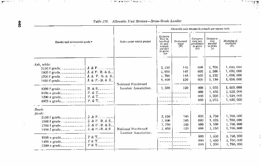
440
P?,- y±.-îi
■■fs
Table 176. Allowable Unit Stresses—Stress-Grade Lumber
Species and commercial grade •
Ash, white: 2150 f grade, 1900 f grade, 1700 f grade. 1450 f grade.
1300 f grade. 1450 c grade. 1200 c grade. 1075 c grade.
Beech: Birch:
2150 f grade. 1900 f grade. 1700 f grade. 1450 f grade.
1550 c grade. 1450 c grade. 1200 c grade.
J. & P J. & P.-B. & S. J. & P.-B. & S. J. & P.-B. & S.
B. & S. P. & T. P. & T. P. & T.
Rules under which graded
National Hardwood Lumber Association.
J. & P J. & P.-B. & S_ J. & P.-B. & S_ J. & P.-B. & S_
P & T_ P & T_ P & T_
National Hardwood Lumber Association.
Allowable unit stresses in pounds per square inch
Extreme fiber in bending (f) and tension parallel to grain
(t)°
2, 150 1, 900 1, 700 I, 450
1, 300
2, 150 1,900 1, 700 1, 450
Horizontal shear (H)
145 145 145 120
120
145 145 145 120
Compres- sion per-
pendicular to grain
(cl)
600 600 600 600
600 600 600 600
600 600 600 600
Compres- sion
parallel to grain
(c)
1, 700 1, 500 1, 325 1, 150
1, 050 1, 450 1, 200 1, 075
1, 750 1, 525 1, 350 1, 150
600 600 600
1, 550 1, 450 1, 200
Modulus of elasticity
(E)
1, 650, 000 1, 650, 000 1, 050, 000 1, 650, 000
1, 650, 000 1, 650, 000 1, 650, 000 1, 650, 000
1, 760, 000 1, 760, 000 1, 760, 000 1, 760, 000
1, 760, 000 1, 760, 000 1, 760, 000

Chestnut: 1450 f grade. 1200 f grade. 1075 c grade
J. & P J. & P.-B. & S__ P. & T
Cypress, southern, coast type (tidewater red) :
1700 f grade 1300 f grade 1450 c grade 1200 c grade
J. & P.-B. & S_. J. & P.-B. & S__ P. & T P. & T
Cypress, southern, inland type: 1700 f grade 1300 f grade 1450 c grade 1200 c grade
J. & P.-B. & S__ J. & P.-B. & S-. P. & T P. & T
Douglas fir, coast region: Dense select structural Select structural 1500 f industrial 1200 f industrial
LF LF LF LF
Dense select structural b Select structural Dense construction b Construction
J. & P J. & P J. & P J. & P
Standard. J. & P
National Hardwood Lumber Association.
1, 450 1, 200
120 120
360 360 300
1, 200 950
1, 075
1, 100, 000 1, 100, 000 1, 100, 000
Southern Cypress Manu- facturers’ Association.
1, 700 1, 300
145 120
360 360 360 360
1, 425 1, 125 1, 450 1, 200
National Hardwood Lumber Association.
1, 700 1, 300
145 120
360 360 360 360
1, 425 1, 125 1, 450 1, 200
1, 320, 000 1, 320, 000 1, 320, 000 1, 320, 000
1, 320, 000 1, 320, 000 1, 320, 000 1, 320, 000
2, 050 1, 900 1, 500 1, 200
c f h 120
e f h 120 120 95
455 415 390 390
1, 500 1, 400 1, 200 1, 000
West Coast Lumber Inspection Bureau. 2, 050
1, 900 1, 750 1, 500 1, 200
c f b 120
„ f b !20
e B b 120
eg!. 120 ugh 95
455 415 455 390 390
1, 650 1, 500 1, 400 1, 200 1, 000
1, 760, 000 1, 760, 000 1, 760, 000 1, 760, 000
1, 760, 000 1, 760, 000 1, 760, 000 1, 760, 000
¡ 1, 760, 000
See footnotes at end of table.

44
2
.K I\f y V; 'S'.. , »«ÖW. ’•■-■v i«*nruni!j.v»«"iyjr
Table 176. Allowable Unit Stresses—Stress-Grade Lumber—Continued
Species and commercial grade * Rules under which graded
Allowable unit stresses in pounds per square inch
Extreme fiber in bending (f) and tension parallel to grain
(t)«
Horizontal shear (H)
Compres- sion per-
pendicular to grain
(cl)
Compres- sion
parallel to grain
(c)
Modulus of elasticity
(E)
Douglas fir, coast region—Con. Dense select structural b__ Select structural Dense construction b Construction
Dense select structural b_ Select structural Dense construction b Construction
B. & S. B. & S_ B. & S. B. & S,
P. & T_ P. & T_ P. & T_ P. & T_
West Coast Lumber Inspection Bureau.
2, 050 1, 900 1, 750 1, 500
i 120 ¡ 120 ¡ 120 ¡ 120
455 415 455 390
1, 500 1, 400 1, 200 1, 000
1, 900 1, 750 1, 500 1, 200
' 120
i 120
i 120
¡ 120
455 415 455 390
1, 650 1, 500 1, 400 1, 200
1, 760, 000 1, 760, 000 1, 760, 000 1, 760, 000
1, 760, 000 1, 760, 000 1, 760, 000 1, 760, 000
Douglas fir, inland region: Select structural b Structural Common structural..
J. & P.d_ J. & P.d_ J. & P.d_
2, 150 1, 900 1, 450
145 100 95
455 400 380
1, 750 1, 400 1, 250
Western Pine Association. Select structural b___ Structural Common structural.
P. & T_ P. & T_ P. & T_
455 400 380
1, 750 1, 400 1, 250
1, 760, 000 1, 650, 000 1, 650, 000
1, 760, 000 1, 650, 000 1, 650, 000

443
Elm, rock:
2150 f grade. 1900 f grade. 1700 f grade. 1450 f grade. 1550 c grade. 1450 c grade. 1200 c grade.
Elm, soft; Gum, black and red; Tupelo:
1700 f 'grade 1450 f grade 1200 f grade 1075 c grade
Hemlock, eastern: Select structural Prime structural Common structural. Utility structural... Select structural
Hemlock; West Coast: Select structural. 1500 f industrial. 1200 f industrial.
Select structural. Construction Standard
J. & P___, J. & P.-B. & S_ J. & P.-B. & S_ J. & P.-B. & S. P. & T. P. & T P. & T
J. & P J. & P.-B. & S. J. & P.-B. & S_ P. & T
J. & P.-B; & S. J. & P.» " J. & P.<i » J. & P.<< ■■ P. & T
LF_ LP. LF_
J. & P_ J. & P. J. & P.
National Hardwood Lumber Association.
National Hardwood Lumber Association.
Northern Hemlock and Hardwood Manufac- turers’ Association.
West Coast Lumber Inspection Bureau.
2,150 1, 900 1, 700 1, 450
J, 700 1, 450 1, 200
I, 300 1, 200 1, 100
950
1, 600 1, 500 1, 500
1, 600 1, 500 1, 200
145 145 145 120
120 .120 120
85 60 60 60
» ' 1 100
100 80
°> 100 » ti loo
« t ' 80
600 600 600 600 600 600 600
300 300 300 300
360 360 360 360 360
365 365 365
365 365 365
•1, 750 1, 525 1, 350 1, 150 1, 550 1, 450 1, 200
1, 225 1, 050
875 1, 075
850 775 650' 600 850
1, 100 1, 000
900
1, 430, 000 1, 430, 000 1, 430, 000 1, 430, 000 1, 430, 000 1, 430, 000 1, 430, 000
1, 200 1, 100 1, 000
1, 320, 000 1, 320, 000 1, 320, 000 1, 320, 000
1, 210, 000 1, 210, 000 1, 210, 000 1, 210, 000 1, 210, 000
1, 540, 000 1, 540, 000 1, 540, 000
1, 540, 000 1, 540, 000 1, 540, 000
See footnotes at end of.table.

444
ipt'¡ilv »■'■T-' »ptt uyi 1 irj
Table 176. Allowable Unit Stresses—Stress-Grade Lumber—Continued
Species and commercial grade ° Rules under which graded
Allowable unit stresses in pounds per square inch
Extreme fiber in bending (f) and tension parallel to grain
(«•
Horizontal shear (H)
Compres- sion per-
pendicular to grain
(cl)
Compres- sion
parallel to grain
(c)
Modulus of elasticity
(E)
Hemlock: West Coast—Con. Construction
Construction.
Hickory, Pecan: 2150 f grade- 1900 f grade. 1700 f grade-
1550 c grade- 1450 c grade. 1325 c grade.
Larch: Select structural b. _ Structural Common structural.
Select structural b_. Structural Common structural.
B. & S. West Coast Lumber Inspection Bureau.
1, 500 100 365 1, 000
P. & T. 1, 200 100 365 1, 100
J. & P.-B. & S. J. & P.-B. & S. J. & P.-B. & S_ National Hardwood
Lumber Association.
2, 150 1, 900 1, 700
145 145 145
720 720 720
1, 725 1, 550 1, 350
P. & T. P. & T- P. & T.
720 720 720
1, 550 1, 450 1, 325
J. & P.'1- J. & P.J. J. & P.<i_
2, 150 J, 900 J, 450
145 120 120
455 415 390
1, 750 1, 450 1, 325
Western Pine Association. P. & T_ P. & T_ P. & T.
455 415 390
1, 750 1, 450 1, 325
1, 540, 000
1, 540, 000
1, 980, 000 1, 980, 000 1, 980, 000
1, 980, 000 1, 980, 000 1, 980, 000
1, 650, 000 1, 650, 000 1, 650, 000
1, 650, 000 1, 650, 000 1, 650, 000
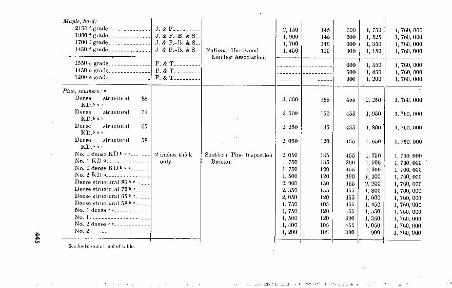
445
Maple, hard: 2150 f grade 1900 f grade 1700 f grade 1450 f grade
1550 c grade 1450 c grade 1200 c grade
Pine, southern: °
Dense structural 80 KD.b « ■■
Dense structural 72 KD.b 1 r
Dense structural 65 KD> -J '
Dense structural 58 KD.b » ’
No. 1 dense KD b a r 2 inches thick No. 1 KD q only. No. 2 dense KD b « r No. 2 KD a Dense structural 86.b r Dense structural 72.b r Dense structural 65.b r Dense structural 58.b r No. 1 dense b r No. 1 No. 2 dense b r No. 2
Sou footnotes at end of table.
J. & P J. & P.-B. & S. J. & P.-B. & S. J & P.-B. & S.
P. & T P. & T P. & T.
National Hardwood Lumber Association.
Southern Pine Inspection Bureau.
2, 150 1, 900 1, 700 1, 450
3, 000
2, 500
2, 250
2, 050
2, 050 1, 750 1, 750 1, 500 2, 900 2, 350 2, 050 1, 750 1, 750 1, 500 1, 400 1, 200
145 145 145 120
165
150
135
120
135 135 120 120 150 135 120 105 120 120 105 105
600 600 600 600
600 600 600
1, 750 1, 525 1, 350 1, 150
1, 550 1, 450 1, 200
455
455
455
455
455 390 455 390 455 455 455 455 455 390 455 390
2, 250
1, 950
1, 800
1, 650
1, 750 1, 500 1, 300 1, 100 2, 200 1, 800 1, 600 1, 450 1, 550 1, 350 1, 050
900
1, 760, 000 1, 760, 000 1, 760, 000 1, 760, 000
1, 760, 000 1, 760, 000 1, 760, 000
1, 760, 000
1, 760, 000
1, 760, 000
1, 760, 000
1, 760, 000 1, 760, 000 1, 760, 000 1, 760, 000 1, 760, 000 1, 760, 000 1, 760, 000 1, 760, 000 1, 760, 000 1, 760, 000 1, 760, 000 1, 760, 000

446
Table 176. Allowable Unit Stresses—Stress-Grade Lumber—Continued
Species and commercial grade a Rules under which graded
Allowable unit stresses in pounds per square inch
Extreme fiber in bending (f) and tension parallel to grain
(t)«
Horizontal shear (hi)
Compres- sion per-
pendicular to grain
(cl)
Compres- sion
parallel to firaln
Modulus of elasticity
(E)
Pine, southern—Continued Dense structural 86.b ' Dense structural 72.b r
Dense structural 65.b r
Dense structural 58.b ' No. 1 dense SR b r No. 1 SR No. 2 dense SR b r No. 2 SR
Dense structural 86 b ’ Dense structural 72 b 1
Dense structural 65 b 1
Dense structural 58 b
No. 1 dense SR b r_ No. 1 SR No. 2 dense SR b r. No. 2 SR
Southern Pine Inspection Bureau.
3 inches and 4 inches thick.
5 inches thick and up.
2, 900 2, 350 2, 050 1, 750 1, 750 1, 500 1, 400 1, 200
p 2, 400 p 2, 000 p 1, 800 p 1, 600 p 1, 600 p 1, 400 p 1, 400 p 1, 200
150 135 120 105 120 120 105 105
150 135 120 105 120 120 105 105
455 455 455 455 455 390 455 390
2, 200 1, 800 1, 600 1, 450 1, 750 1, 500 1, 050
900
455 455 455 455 455 390 455 390
1, 800 1, 550 1, 400 1, 300 1, 500 1, 300 1, 050
900
1, 760, 000 1, 760, 000 1, 760, 000 1, 760, 000 1, 760, 000 1, 760, 000 1, 760, 000 1, 760, 000
1, 760, 000 1, 760, 000 1, 760, 000 1, 760, 000 1, 760, 000 1, 760, 000 1, 760, 000 1, 760, 000

533506
Industrial 86 KD Industrial 72 KD Industrial 65 KD a Industrial 58 KD Industrial 50 KD a. Industrial 86 Industrial 72 Industrial 65 Industrial 58 Industrial 50
1 inch, l}i inches, and Ijri inches thick.
2, 600 2, 200 2, 000 1, 750 1, 500 2, 500 2, 000 1, 750 1, 500 1, 200
165 150 135 120 120 150 135 120 105 105
390 390 390 390 390 390 390 390 390 390
1, 950 1, 650 1, 550 1, 400 1, 100 1, 900 1, 550 1, 350 1, 250
900
1, 760, 000 1, 760, 000 1, 760, 000 1, 760, 000 1, 760, 000 1, 760, 000 1, 760, 000 1, 760, 000 1, 760, 000 1, 760, 000
Oak, red, and white: 2150 f grade.- 1900 f grade.- 1700 f grade.. 1450 f grade..
1300 f grade_ 1325 c grade_ 1200 c grade. 1075 c grade.
Pine, Norway: Prime structural Common Structural- Utility structural
J. & P J. & P.-B. & S. J. & P.-B. & S. J. & P.-B. & S. National Hardwood
Lumber Association.
2, 150 1, 900 1, 700 1, 450
145 145 145 120
600 600 600 600
1, 550 1, 375 1, 200 1, 050
B. & S. P. & T. P. & T. P. & T.
1, 300 120 600 600 600 600
950 1, 325 1, 200 1,075
J. & P.e n. J. & P.e D. J. & P.» n.
National Hemlock and Hardwood Manufac- turers’ Association.
1, 200 1, 100
950
75 75 75
360 360 360
900 775 650
1, 650, 000 1, 650, 000 1, 650, 000 1, 650, 000
1, 650, 000 1, 650, 000 1, 650, 000 1, 650, 000
1, 320, 000 1, 320, 000 1, 320, 000
•u N
Poplar, yellow: 1500 f grade. 1250 f grade. 1075 c grade.
J. & P. J. & P.- P. & T.
B. & S_. National Hardwood
Lumber Association. 1, 500 1, 250
110 110
300 300 300
1, 200 950
1, 075
1, 210, 000 1, 210, 000 1, 210, 000
See footnotes at end of table.
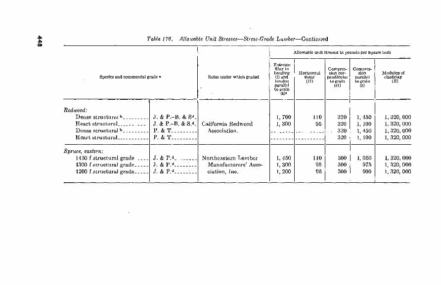
448
Table 176. Allowable Unit Stresses—Stress-Grade Lumber—Continued
Species and commercial grade »
Redwood: Dense structural b_ Heart structural Dense structural b. Heart structural
J. & P.-B. & S'1. J. & P.-B. & SA P. & T P. & T
Rules under which graded
California Redwood Association.
Allowable unit stresses In pounds per square inch
Extreme fiber in bending (I) and tension parallel to grain
(t)°
1, 700 1, 300
Horizontal shear (ID
no 95
Compres- sion per-
pendicular to grain
(cl)
320 320 320 320
Compres- sion
parallel to grain
(c)
1, 450 1, 100 1, 450 1, 100
Modulus of elasticity
(E)
1, 320, 000 1, 320, 000 1, 320, 000 1, 320, 000
Spruce, eastern: 1450 f structural grade 1300 f structural grade, 1200 f structural grade.
J. & P.A J. & PA J. & PA
Northeastern Lumber Manufacturers’ Asso- ciation, Inc.
1, 450 1, 300 1, 200
110 95 95
300 300 300
1, 050 975 900
1, 320, 000 1, 320, 000 1, 320, 000

449
Abbreviations. (For description of classification of matoi ml, see paragraph 102-11.) ,T. & P.=joists and planks. B. & S. = beams and stringers. I'. & T. = posts and timbers. BF = Kght framing. KD=seenotcq. SR=stross rated.
b These grades meet the requirement for density. A In tension members the slope of grain limitations applicable to the middle portion
of the length of the joist-and-phuik and beam-and-stringcr grades used shall apply throughout the length of the piece.
d The allowable unit stresses for tension parallel to grain (t) ami for compression parallel to grain (c) given for these joist-and-plnnk and beam-and-stringcr grades arc applicable when the following additional provisions are applied to the grades: the sum of the sizes of all knots in any 0 inches of the length of the piece shall not exceed twice the maximum permissible size of knot; two knots of maximum permissible size shall not be within the same 6 inches of length of any face.
« Value applies to pieces used as planks. , < Value applies to 2-inch-thick pieces of select structural grade used as joists. « For 2-inch-thick pieces of construction and standard grades used as joists:
11=120 when length of split is approximately equal to one-half the width of piece.
11=100 when length of split is approximately equal to the width of piece. 11=70 when length of split is approximately equal to times width of piece,
fa For 3-inch-thick pieces of select structural, construction, and standard grades used as joists:
11=120 when length of split is approximately 2^ inches. H=80 when length of split is approximately inches, and for 4-inch-thick
pieces of select structural, construction, and standard grade used as joists- 11=120 when length of split Is approximately 3 inches. H=80 when length of split is approximately G inches.
* For beams and stringers and for posts and timbers- H=120 when length of split is equal to one-half the nominal narrow face di-
mension. H = 100 when length of split is equal to the nominal narrow face dimension. H=80 when length of split is equal to lj^ times the nominal narrow face di-
mension. i Pieces of less than medium grain, when included in the grade of STANDARD
may be considered as having a modulus of elasticity (E) of 1,320,000. k For 2-inch-thick pieces of construction and standard grades used as joists:
11=100 when length of split is approximately equal to one-half the width of piece.
H=80 when length of split is approximately equal to the width of piece.. H=G0 when length of split Is approximately equal to 1H times the width of
piece.
i Kor d-inch-tliick pircos of select structura], construction, and standard grades used as joists:
II = 100 when length of split is approximately 2)4 inches. li = 70 when length of split is approximately inches, and for 4-inch-thick
pieces of select structural, construction, and standardgradcs used as joists- 11 = 100 when length of split is approximately 3 inches. If=s70 when length of split is approximately G inches.
m For beams and stringers and for posts and timbers: 11 = 100 when length of split is equal to % the nominal narrow face dimension. i l=90 when length of split is equal to the nominal narrow face dimension. H=70 when length of split is equal to times the nominal narrow face di-
mension. n These grades applicable to 2-inch thickness only. o All stress grades under the 195G grading rules are all-purpose grades and apply
to all sizes. Pieces so graded may be cut to shorter lengths without impairment of the
stress rating of the shorter pieces. Grade restrictions provided by the 1956 grading rules
apply to the entire length of the piece, and each piece is suitable for use in continuous
spans, o\Ter double spans, or under concentrated loads without regrading for special
shear or other special stress requirements. The following variations apply to the
provisions of paragraph 202-B for lumber In service under wet conditions or where the
moisture content is at or above fiber saturation point, as when continuously submerged:
(1) the allowable unit stresses in bending, tension parallel to grain, and horizontal shear
shall be limited in all thicknesses to the stresses Indicated for thicknesses of 5 inches
and up; (2) the allowable unit stresses for compression parallel to grain shall be limited
to the stresses indicated for thicknesses of 5 inches and up reduced by 10 percent; (3)
the allowable unit stresses for compression perpendicular to grain shall be reduced one-
third; and (4) the values for modulus of elasticity shall be reduced by one-eleventh.
p These stresses apply for loading either on narrow face or on wide face, which is an
exception to pars. 102-B-l and 205-B.
9 KD=kiln dried in accordance with the provisions of pars. 219 and 220 of the 1956
grading rules.
r Longlcaf may be specified by substituting “longleaf" for “denscM in the grade
name, and when so specified the same allowable stresses shall apply.
Values for lengths of split other than those given in *, h, and 1 are proportionate.
Values for lengths of splits other than those given in k, ', and “ are proportionate.
Reprinted by permission of the National Lumber Manufacturers’ Association
from “National Design Specification for Stress-Grade Lumber and Its Fastenings,”
revision of 1955.

F
Sv
g
174. Dimensions and Properties Table 177 is an abridged list of American standard dressed sizes of
dimension lumber, with moments of inertia and section moduli. It is assumed that the greater dimension of cross section (=A) is vertical.
Table 177. Dressed Sizes of Lumber
Nominal size American standard
Area of section sq in. S = -
1 x 3-- 1x4-- 1 x 6. _ 1 x 8_- 1 x 10_ 1 x 12- 2 x 4__ 2 x 6. _ 2 x 8_ _ 2 x 10-- 2 x 12- 3 x 8_ _
x 10- x 12- x 12- x 16- x 12- x 16-
6 x 18- 8 x 16- 8 x 20- 8 x 24-
% x 2%2 X
2%2 X
2S/32 X
1% X
1% X
1% -X
1% X
1% X
2% x 2% x 2% x 3% x 3^ x b'A x b'A X
5K X 7/2 x 7/2 x 7H x
2% 3ïs bVs 7/2 9K U'A sys
7/2 9/2 11/2 7/2
9/ 11/ 11/ 15/ 11/ 15/ 17/ 15/ 19/ 23/
In.2
2. 05 2. 83 4. 39 5. 86 7. 42 8. 98 5. 89 9. 14
12. 19 15. 44 18. 69 19. 69 24. 94 30. 19 41. 69 56. 19 63. 25 85. 25 96. 25
116. 25 146. 25 176. 25
In.4
1. 18 3. 10
11. 59 27. 47 55. 82 99. 02
6. 45 24. 10 57. 13
116. 10 205. 95
92. 29 187. 55 332. 69 459. 43 124. 92 697. 07
1, 706. 78 2, 456. 38 2, 327. 42 4, 634. 30 8, 111. 17
1
In.3
0. 90 1. 71 4. 12 7. 32
11. 75 17. 22
3. 56 8. 57
15. 23 24. 44 35. 82 24. 61 39. 48 57. 86 79. 90
145. 15 121. 23 220. 23 280. 73 300. 31 475. 31 690. 31
1 75. Beam Design a. Timber beams are designed using the beam formulas in paragraph
146 and the unit stresses in paragraph 173. For beams in which flexure controls, table 178 is used.
b. If deflection is the controlling factor or is limited to /eo span (the usual requirement where plastered ceilings occur), use the de- flection formulas in paragraph 133. For the beam in the example of table 160, carrying its full load of 20,300 pounds—
Deflection= 5 w l4
384E1 4X20,300X(16X12)3
384X1,760,000X1,540 =0.69 inch
Allowable deflection= 12X16
360 =0.53 inch
450
¡< it
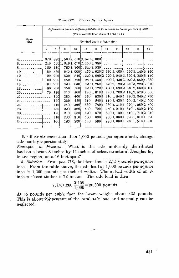
Table 17S. Timber Beams Loads
Span (ft.)
Safe loads in pounds uniformly distributed for rectangular beams per inch of width
(For allowable fiber stress of 1,000 p.s.i.)
Nominal depth of beam (in.)
10 10 18 22 24
4..
6-.
8--
10.
12.
14. 16- 18- 20-
22.
24. 26_ 28. 30- 32. 34.
370 240 180 150 120 100 90 80 70
880 590 440 350 290 250 220 200 180 160 150 140 130 120 110 100
1, 560 1, 040
780 630 520 450 390 350 310 280 260 240 220 210 200 180
510 670 260 000 840 720 630 560 500 460 420 390 360 330 310 290
670 450 840 470 220 050 920 820 730 670 610 560 530 490 460 430
060 380 530 020 690 450 260 120 010 920 840 780 720 670 630 590
670 220 900 670 480 330 210 110 030 950 890 830 780
400 840 430 120 890 700 540 420 310 210 130 060 000
220 520 020 640 340 HQ 920 760 620 510 410 320 240
140 280 660 220 860 570 340 140 980 830 710 610 510
6, 140 5, 110 4, 380 3, 840 3, 400 3, 060 2, 790 2, 560 2, 360 2, 190 2, 040 1, 920 1, 810
For fiber stresses other than 1,000 pounds per square inch, change safe loads proportionately. Example, a. Problem. What is the safe uniformly distributed load on a beam 8 inches by 14 inches of select structural Douglas fir, inland region, on a 16-foot span?
b. Solution. From par. 173, the fiberstress is 2,150poundspersquare inch. From the table above, the safe load at 1,000 pounds per square inch is 1,260 pounds per inch of width. The actual width of an 8- inch surfaced timber is 7K inches. The safe load is then
7^X1,260 |^=20,300 pounds
At 35 pounds per cubic foot tbe beam weighs about 435 pounds. This is about'2/ir pereent of the total safe load and normally can be neglected.
451

To hold deflection to Keo of the span for building design, the load is reduced to 5%g of 20,300 or 15,600 pounds, or a deeper beam is selected.
c. Horizontal shear is likely to be the controlling factor in the safe loads for relatively short beams loaded to full flexural strength; it rarely affects the design of longer beams. Safe loads are given in table 179.
Table 179. Safe Loads for Short Beams
Safe loads in pounds uniformly distributed for rectangular beams, per Inch of width (For allowable horizontal shear of 100 pounds per square Inch)
Depth (inches)
4 6 8
10
Safe load (pounds)
480 750
1, 000 1, 260
Depth (inches)
12 14 16 18
Safe load (pounds)
1, 530 1, 800 2, 060 2, 330
Depth (inches)
20 22 24
Safe load (pounds)
2, 600 2, 870 3, 130
For allowable stresses other than 100 pounds per square inch, change safe loads proportionately. Example. Assume the 8-inch by 14-inch beam in the example in table 160 is used on a 10-foot span. The allowable load due to flexure is—
7^X2,020XY^=32,600 pounds
Allowable load due to horizontal shear (stress is given as 145 pounds per square inch in paragraph 161):
145 7^X1,800X^=19,600 pounds
In this case the shear controls the allowable load.
1 76. Column Design
a. The safe axial load for a wood column of square or rectangular cross section is given by the formula—
P ,0-30Æ {Ijdf
Where P=safe load in pounds A = cross-sectional area in square inches 2?=modulus of elasticity in psi ¿=length (height) of column, in inches d=dimension of the least side of the cross section, in inches.
(It is to be noted that, for dressed lumber, this is the actual dimension, not the nominal.)
In this formula, P/A must not exceed c, the allowable unit stress in compression, parallel to grain, for the wood in question.
452

Table 180. Safe Loads—Dressed-Lumber Columns
Nominal dimensions of cross section (inches)
4 by 4_
4 by 6.
6 by 6.
6 by 8.
8 by 8.
8 by 10.
10 by 10.
8 by 12.
10 by 20.
12 by 12.
Length (feet)
6 8
10
8 10 12
8 10 12
10 12 14 16
10 12 14 16
10 12 14 16 18
10 12 14 16 18
10 12 14 16 18
12 14 16 18 20
12 14 16 18 20
Safe load (kips)
17. 5 9. 9 6. 3
15. 3 9. 8 6. 8
52. 1 33. 6 23. 3
45. 8 31. 7 23. 4 17. 9
116. 0 80. 5 59. 2 45. 3
147. 0 102. 0
75. 0 57. 4 45. 4
300. 1 206. 3 152. 1 116. 8 92. 5
178. 0 123. 5 90. 7 69. 5 55. 0
249. 7 184. 1 141. 4 112. 0 90. 1
446. 7 327. 6 250. 3 197. 6 159. 9
453

b. Some representative values of safe loads in dressed-lumber columns are given in table 180, based on £'=1,760,000, the accepted value for southern pine and coastal Douglas fir.
1 77. Connections in Wood Framing In wood trusses and similar structures, sizes of members may be
controlled by the thickness and width necessary for the design of connections which will transmit the stresses. Working loads for various fastenings are as follows: -
a. Nails and Spikes. The safe lateral load for one nail or spike driven into the side grain of seasoned lumber so that at least two- thirds of the length of the nail is in the wood member holding the point (reduce load 60 percent for nails in end grain and 25 percent for unseasoned wood) is as follows:
900 XD3'2 for white pine and eastern hemlock . 1200 XD3/2 for Douglas fir and southern yellow pine 1700XD3/2 for oaK, ash, and hard maple
Where D = diameter of nail, in inches. Table 181 shows various nail and spike sizes.
Table 181. Nail and Spike Sizes
Size Length (inches)-
Gage Diameter (D) (inches)
D3/2
Nails-
Spikes-
3d 4d 6d 8d
lOd 16d 20d 30d 40d 60d
7” 8"
9” 10"
12"
iy/' IK" 2"
2K" 3" 3K" 4" 4y2" 5" 6"
7" 8"
9" 10"
12"
14 12K UK 10K
9 8 6 5 4 2
K" H" Vs" K"
0. 0800 . 0985 . 1130 . 1314 . 1483 . 1620 . 1920 . 2070 . 2253 . 2625
Ks"
0. 0226 . 0309 . 0380 . 0476 . 0570 . 0652 . 0841 . 0942 . 1066 . 1347
0. 1750 . 2295 . 2295 . 2295 . 2295
b. Wood Screws. The safe lateral load for one wood screw driven into the side grain of seasoned lumber to a penetration of at least seven times its diameter into the member receiving the point (reduce load 25 percent for end grain and 25 percent for unseasoned wood) is as follows:
2100XD2 for white pine and eastern hemlock 2700 XD2 for Douglas fir and southern yellow pine 4000 XD2 for oak, ash, and hard maple
454

Table 182. Wood Screw Diameters
Size
'A inch—No. 4_-. % inch—No. 8 1 inch—No. 10_ - V/i inch—No. 12_ 2 inch—No. 14_. ‘¿'A inch—No. 16- 3 inch—No. 18--
Diametcr-D D2
Inches
0. 1105 . 1631 . 1894 . 2158 . 2421 . 2684 . 2947
Inches2
0. 0122 . 0266 . 0359 . 0466 . 0586 . 0720 . 0868
Where D = diameter of shank of screw, in inches. Typical wood-screw diameters are shown in table 182.
c. Lag Screws. (1) The safe lateral load for one lag screw driven into the side
grain of seasoned lumber to a penetration of nine times the diameter into the member receiving the point and holding a cleat having a thickness of 3.5 times the screw diameter (reduce load 35 percent for end grain and 25 percent for unseasoned wood) is as follows: 1500XD2 for white pine and eastern hemlock 1700XD2 for Douglas fir and southern cypress 1900XD2 for southern yellow pine and soft maple 2200XD2 for oak, ash, and hard maple
Where D = diameter of shank, in inches. (2) If the cleat thickness is more or less than 3A times the screw
diameter, use percentages of safe loads as shown in figure 84. (3) If the penetration of the lag screw into the member receiving
the point is more than nine times the screw diameter; that is, if the unthreaded shank penetrates the members, the load may be increased by the percentages in figure 85, up to an increase of 39 percent for a penetration of 7 or more diameters of the shank.
d. Bolts. (1) Basic stresses. The basic allowable working stresses for the
design of bolted joints in various species are shown in table 183.
(2) Stress reductions. The above basic stresses apply to the bear- ing area (bolt diameter times length of contact area) of a member in double shear; that is, a main tension member with metal splice plates on both faces or wood splice plates one-half the thickness of the main member, except that for tension member with wood splice plates the stress used is reduced by 20 percent. The basic stresses apply to seasoned
455
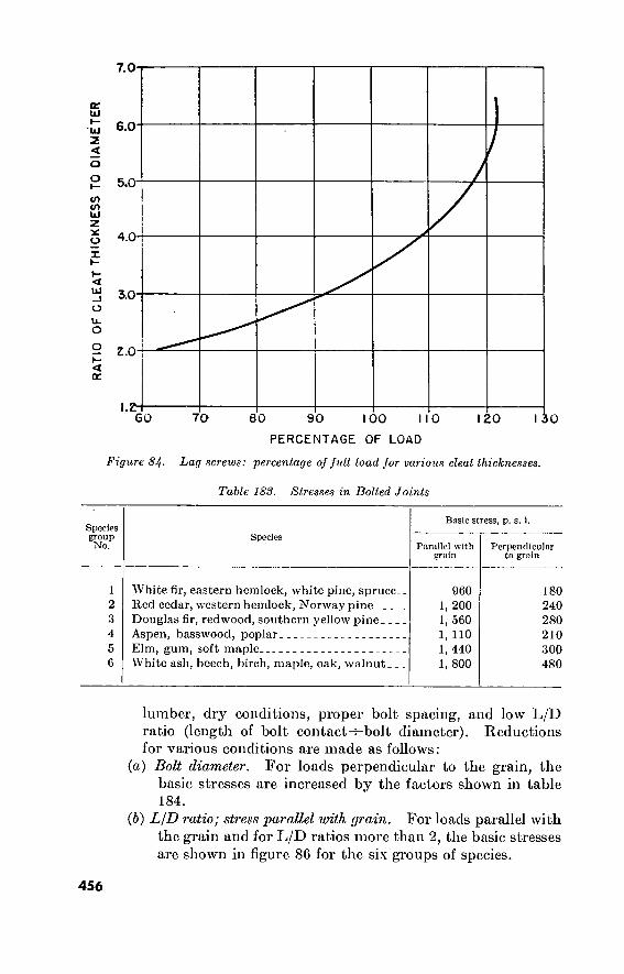
7.0
4.0
3.0
^ Z.O
GO 70 20 80 90 100 110
PERCENTAGE OF LOAD
Figure 84- Lag screws: percentage of full load for various cleat thicknesses.
Table 183. Stresses in Bolted Joints
Species group No.
Species
Basic stress, p. s. i.
Parallel with grain
Perpendicular to grain
1 White fir, eastern hemlock, white pine, spruce. 2 Red cedar, western hemlock, Norway pine 3 Douglas fir, redwood, southern yellow pine 4 Aspen, basswood, poplar 5 Elm, gum, soft maple 6 White ash, beech, birch, maple, oak, walnut
960 1, 200 1, 560 1, 110 1, 440 1, 800
180 240 280 210 300 480
lumber, dry conditions, proper bolt spacing, and low L/D ratio (length of bolt contact-^bolt diameter). Reductions for various conditions are made as follows:
(а) Bolt diameter. For loads perpendicular to the grain, the basic stresses are increased by the factors shown in table 184.
(б) L/D ratio; stress parallel with grain. For loads parallel with the grain and for L/D ratios more than 2, the basic stresses are shown in figure 86 for the six groups of species.
456

8
110 IZO 130
PERCENTAGE OF LOAD
140
Figure 85. Lag screws: percentage of full load for penetration in excess of nine diameters.
(c) L/D ratio; stress 'perpendicular to grain. For loads perpen- dicular to the grain, the stresses are reduced as shown in figure 87.
(d) Exposure and seasoning. For joints exposed to the weather, use 75 percent of values otherwise obtained; 67 percent if usually wet or damp; and 33 percent for green lumber allowed to season under load.
(3) Example. A main tension member 4 inches thick (actually 3%) of seasoned Douglas fir for use indoors, connected by four %-inch bolts through wood splice plates. Bearing area, 3.625X0.75, is 2.72 square inches L/D ratio, 3.625^-0.75, is 4.83, for which (2)(6) above gives a unit stress of 1370 for group 3. Reducing 20 percent for wood splice plates brings this to 1095 pounds per square inch. The allowable load is 1095X2.72X4, or about 11,900 pounds.
457

o w
>
■ Table 184- Boll Diameter Stress Factors
Bolt diameter (inches) Diameter factor
2. 50 1. 95 1. 68 1. 52 1. 41 1. 33 1. 27
Bolt diameter (inches)
D4-
I'A- IK- 2__.
2H 3 and over.
Diameter factor
1. 19 1. 14 1. 10 1. 07 1. 03 1
e. Timber Connectors. (1) Types available. The types of timber connectors which are
standard items of issue include the 2}¿- and 4-inch split ring and the 4-inch toothed ring. The design data below cover the split-ring connector, which is the type regularly used. It is installed quickly and accurately in a groove made by a cutter in a %-inch electric drill, whereas the toothed ring is embedded by drawing the timbers together with a high- strength bolt with smooth thread and a ball-bearing washer, to be then replaced by the regular bolt. The 4-inch toothed- ring connector has design values about 10 percent below those of the 4-inch split ring. It is used in comparatively light construction or in isolated locations where a heavy-duty drill is not available. Bolt diameters are }{ inch for 2%-inch rings,- % inch for 4-inch rings. Plate washer sizes are 2 by 2 by % inch and 3 by 3 by Ke inch for 2}(- and 4-inch rings, respectively.
(2) Species groups. The connector load groupings for various species of lumber of structural grades are as follows :
Connector load group Species
Dense Douglas fir, oak, and longleaf yellow pine. Coastal Douglas fir, larch, and shortleaf yellow pine. Cypress, western hemlock, Norway pine, and redwood.
(3) Edge and end distances. Minimum distances from center of connector to edges and end of members are shown in figures 88, 89, 90, and 91.
458

L/D
RA
TIO
Í 2
< cr
o 's.
300 600 900 1200
UNIT WORKING STRESS
1500
300 600 1500 900 1200
UNIT WORKING STRESS
Figure 86. Bolted joints: unit working stresses for loads 'parallel with grain.
1000
< ÛC Û \
12 ■
10-
8
6
4
O
C J CO
T7 CJ
0 100 200 300 400 500
UNIT WORKING STRESS
< cc
Û
_l
I 0
try
O O
100 200 300 400 500
UNIT WORKING STRESS
Figure 87. Bolted joints: unit working stresses for loads perpendicular to grain.
459

PE
R
CE
NT
PE
R
CE
NT
O
F F
UL
L L
OA
D
OF F
UL
L L
OA
D IOO
90 «5
ANGL ANGL
.ES Sh l ES OF
OWN A LOAD
RE TO GRAIN
3 23/4 2
EDGE DISTANCE (inches)
Figure 88. Edge distance for Zy-i-inch split rings.
100 'S
90
ANG
ANG
_ES S HOWN ARE
.ES 0: LOAl TO (;RAIN
3 3/4 3 EDGE DISTANCE (inches)
Figure 89. Edge distance for 4-inch split rings.
460

PE
R C
EN
T
OF
FU
LL
LO
AD
IOO
END DISTANCE (inches)
7 6 5 4
9 Ï "öfi i nr P i s
4 90 <<
Qi
80
\ •p *
v C\ 70
Tc on
62.5 6 5 4 3 4
END DISTANCE (inches)
Figure 90. End distance for S'A-inch split rings.
461

100
END DISTANCE (inches)
5 6 5 4 3
'i
cm s: on 'I.
90 <f
Y. o o y :
\ O
■P \ 70 5 Tîrsi or \
1.5 5 4 3 3
END DISTANCEÍ inches)
Figure 91. End distance for 4-inch split rings.
(4) Spacing. (a) For 2%-inch rings, 3K-inch spacing is minimum and permits
applying 75 percent of the full loads given below. For full load and various angles of load to grain, spacings vary from 4% inches perpendicular to grain for loads at 60° to 90° with the grain, to 6% inches parallel with the grain for loads parallel with the grain.
(b) For 4-inch rings, the above values are: 5-inch spacing for 75 percent loading varying to 6-inch spacing perpendicular to grain and' 9-inch spacing parallel with grain for loads parallel with the grain.
(5) Allowable loads. For satisfactory distances and spacing, and for long-term or permanent loading, safe loads per connection are shown in figures 92 and 93. The values may be increased 15 percent for loads applied for periods of not over 3 months or for snow loads, 50 percent for 0 wind or earthquake loads, or 100 percent for impact loads.
462

LO
AD
in
PO
UN
DS
ANGLE of LOAD to GRAIN
4000
3300
30 0 0
3000
25 00
2 5 00
20 00
I 500
1000
0° 10° 20° 30° 40° 30° 60° 70° 00° 90° i—I— 4000
OU F -A 3300
%
aí
â 4* ft 3000
ISO
■fe fe A
% 2 500
£k
i'j
2 000
At
rr Qu
5Ltv 4. X w, »
<9 -GRJ31 /Ci
ES ml A
a
m, ton ■èe Ö3
0Ç g? £»
GROUP
Z ooo
I 500
2 000
1500
Ô0' IO8' 206 30* 40* 50° 60° 70° 80° 90°
ANGLE of LOAD to GRAIN
10 00
Figure 92. Safe loads for one SYi-inch ring and bolt in single shear.
463
•533506*—60 30
LO
AD
in
PO
UN
DS

LOA
D
in
PO
UN
DS
ANGLE of LOAD to GRAIN
10» 20» 30“ 40° 50» 60» 70» 80° 90° 7000
6500
6 000
5500
5000
4500
5500
5 000
4500
4000
4500
4000
3500
3 000
2500
2000
a '
Í37
tí •f|
P77
ST»
! in
Le.
» 1 «
a 7*
7000
6500
6000
5500
5000
45 00
4000
3500
3000
4000
3500
3000
2500
3500
3000
2500
2000
0» t0° 20» 30° 40» 50» 60» 70» 80° 90»
ANGLE of LOAD to GRAIN
Figure 9S. Safe loads for one 4-inch ring and bolt in single shear.
464
LO
AD
in
PO
UN
DS

CHAPTER 10
MATERIALS OF CONSTRUCTION
Section I. WOOD
1 78. Board Measure a. Lumber quantities are expressed in feet, board measure (ft. b.m.)
or in board feet (bd. ft.), or in thousand board feet (M bd. ft.). One board foot (or ft. b.m.) is the amount of lumber in a rough-sawed board 1 foot long, 1 foot wide, and 1 inch thick (144 cubic inches) or the equiv- alent volume in any other shape. These original or “nominal” dimen- sions and volumes determine the number of board feet in a given quan- tity of dressed lumber, regardless of the fact that the process of surfacing or other machining has reduced the actual dimensions and volume. Under American standards, for example, a dressed board designated as 1 inch by 12 inches is in fact 2)32 inch by 11}£ inches. This must be taken into account in computing the amount of lumber needed for a given job. Thus, one hundred 1-inch by 12-inch dressed boards
16 feet long contain ^00XIX1-X gQQ boar(j feet) tmt have an i.
actual area of only =1,533 square feet; so that if 1,600
square feet of 1-inch by 12-inch material are desired, 1,670 board feet, plus allowance for wastage, must be ordered.
b. Table 185 gives the number of board feet in one piece of lumber of the sizes given.
1 79. International Log Rule A log rule, or scale, is marked at each inch with the number of
board feet which can be sawed from logs if the log is measured inside the bark at the small end. Many such rules have been devised, recognized in the lumber industry, and used in various localities. The international K-inch log rule, which is based on K-inch saw kerfs, has been adopted by statute in some states and may eventually become the universal standard. In applying the rule, no interpolation is made for diameters between inch marks, but scaling practice in some localities permits using the next higher 'inch for diameters with a fraction larger than 'A inch; for example, a log 23% inches in diameter is scaled as 24 inches. The scale is given in tabic 186.
465

24
16 24 32 40 48 56 64 36 48 60 72 84 96 32 48 64 80 96
112 128
72 96
120 144 168 192 216 240' 128 160 192 224 200 240 280 320 288 336 384 392 448
Table 185. Board Feet
Size of piece (inches)
2 by 4-. 2 by 6-- 2 by 8- 2 by 10. 2 by 12. 2 by 14. 2 by 16. 3 by 6__ 3 by 8.. 3 by 10. 3 by 12. 3 by 14. 3 by 16.
by 4 by 6__.
by 8... by 10. . by 12.. by 14._ by 16-.
6 by 6 6 by 8 6 by 10._ 6 by 12.. 6 by 14. _ 6 by 16-- 6 by 18_- 6 by 20.. 8 by 8 8 by 10.. 8 by 12.. 8 by 14.. 10 by 10. 10 by 12. 10 by 14. 10 by 16. 12 by 12. 12 by 14. 12 by 16. 14 by 14. 14 by 16-
Length of piece (feet)
6% 10 13H 16% 20 23% 26% 15 20 25 30 35 40 13% 20 26% 33% 40 46% 53% 30 40 50 60 70 80 90
100 53% 66% 80 13% 83%
100 116% 133% 120 140 160 163% 186%
8 12
16 20 24 28 32 18 24 30 36 42 48 16 24 32 40 48 56 64 36 48 60 72 84 96
108 120 64 80 96
112 100 120 140 160 144 168 192 196 224
9% 14 18% 23% 28 32% 37% 21 28 35 42 49 56 18% 28 37% 46% 56 65% 74% 42 56 70 84 98
112 126 140
74% 93%
112 130% 116% 140 163% 186% 168 196 224 228% 261%
10%
16 21% 26% 32 37% 42% 24 32 40 48 56 64 21%
32 42% 53% 64 74% 85% 48 64 80 96
112 128 144 160 85%
106% 128 149% 133% 160 186% 213% 192 224 256 261% 298%
18
12 18 24 30 36 42 48 27 36 45 54 63 72 24 36 48 60 72 84 96 54 72 90
108 126 144 162 180 96
120 144 168 150 180 210 240 216 252 288 294 336
13% 20 26% 33% 40 46% 53% 30 40 50 60 70 80 26% 40 53% 66^ 80 93%
106% 60 80
100 120 140 160 180 200 106% 133% 160 186% 166% 200 233% 266% 240 280 320 326% 373%
14% 22 29% 36% 44 51% 58% 33 44 55 66 77 88 29% 44 58% 73% 88
102%
117% 66 88
110 132 154 176 198 220 117% 146% 176 205% 183% 220 256% 293% 264 308 352 359% 410%
466

20
25 40 50 70 85
105 125 150 175 205 235 205 300 335 370 410 455 495 545 590 640 690 745 800 860 915 980
1045 1110 1175 1245 1315 1390 1465 1540 1620 1705 1785 1870 1960 2050 2140 2235
467
Table 186. Log Scale
Length of log in feet (board measure)
8
10 10 15 20 30 35 45 55 65 -75 85 95
110 125 135 155 170 185 205 220 240 260 280 305 325 350 375 400 425 450 475 505 535 565 595 625 655 690 725 755 795 830 865
10
10 , 15
20 30 35 45 55 70 80 95
110 125 140 155 175 195 215 235 255 280 305 330 355 385 410 440 470 500 535 565 600 635 670 710 750 785 825 870 910 955 995
1040 1090
12
15 25 25 35 45 55 70 85
100 115 130 150 170 190 210 235 260 285 310 340 370 400 430 465 495 530 570 605 645 685 725 770 810 855 900 950 995
1045 1095 1150 1200 1255 1310
14
15 30 35 45 55 70 85
100 115 135 155 180 200 225 250 280 305 335 370 400 435 470 510 545 585 625 670 715 760 805 855 905 955
1005 1060 1115 1170 1230 1290 1350 1410 1475 1540
10
20 30 40 50 65 80 95
115 135 160 180 205 230 260 290 320 355 390 425 460 500 540 585 630 675 720 770 820 875 925 980
1040 1095 1155 1220 1280 1345 1410 1480 1550 1620 1695 1770
18
25 35 45 60 75 95
110 135 155 180 205 235 265 300 330 365 405 445 485 525 570 615 665 715 765 820 875 930 990
1050 1115 1175 1245 1310 1380 1450 1525 1600 1675 1755 1835 1915 2000

Section II. STEEL PRODUCTS
180. Corrugated Sheet Metal a. Black sheet iron with 2%-inch corrugations is stocked in oversea
depots as a class IV item, in two sizes as follows :
United States standard gage
28 22
Thickness (inches)
0. 015 . 030
Pounds per square foot 1
0. 68 1. 36
Width (inches)
27 27
Length (feet)
8 11
1 Based on sheets 27 inches wide, lapped 3 inches.
b. Technical data on black and galvanized sheet metal with 2%-inch corrugations are given in table 187.
181. Wire Rope. a. General. Wire rope is manufactured from six types of metal
and in many combinations of wire size, number of wires per strand, number of strands, and core types. Standard hoisting rope is made of 6 strands of 19 wires each, over a hemp core. It is flexible enough to operate over sheaves of practicable sizes. Using smaller wire sizes, ropes of 6 strands of 37 wires and of 8 strands of 19 wires are more flexible and permit smaller sheave sizes. Using larger wires, ropes of 6 strands of 7 wires are suitable for standing rope service, such as guvs and moorings. They require much larger sheaves if used over sheaves.
b. Sheave Sizes. Standard hoisting rope, 6 strands of 19 wires, requires a sheave diameter of 45 times the rope diameter to avoid excessive deterioration from bending stresses, and an absolute mini- mum sheave diameter of 30 times the rope diameter. Recommended
Table 1S7. Black and Galvanized Sheet Metal—S^i-inch Corrugations
U.S. Standard gage
28- 26- 24_ 22.
20-
18- 16- 14. 12.
Thickn e'.s (niche?)
0. 015 . 018 . 024 . 030 . 036 . 048 . 060 . 075 . 105
Pounds per square foot 1
Galvanized
0. 85 . 99
1. 26 1. 53 1. 81 2. 35 2. 90 3. 58 4. 94
Black
0. 68 . 82
1. 09 1. 36 1. 64 2. 18 2. 73 3. 41 4. 77
Maximum span (feet)
Roofing
2' 9” 2' 9” 3' 9" 4' 9" 5' 9" 5' 9” 5' 9" 5' 9” 5' 9”
Siding
3' 10" 3' 10” 4' 10" 5' 10" 5' 10" 5' 10" 5' 10" 5' 10" 5' 10"
1 Based on sheets 27 inches wide, lapped 3 inches. (Reprinted from “Steel Construction” by permission of American Institute of Steel Construction.
Copyright 1947.)
468

and minimum sheave diameters for standard and other wire ropes are given in table 188.
Tabic 188. Sheave Diameters for Wire Rope
Type of wire rope (strands by wires)
Recommended sheave or drum diameter
Minimum sheave or drum diameter
6 by 7.. 6 by 19 6 by 37 8 by 19
72 X rope diameter. 45 X rope diameter. 27 X rope diameter. 31 X rope diameter.
42 X rope diameter. 30 X rope diameter. 18 X rope diameter. 21 X rope diameter.
c. Breaking Strength. While the breaking strength of wire rope varies slightly with the strand construction and number of strands, it depends primarily upon the type of metal used. The breaking strength of standard 6 by 19 hoisting rope, given in table 189 for each type of metal, is about 10 percent higher than that of 6 by 7 standing rope and slightly lower than that of some of the more flexible wire ropes.
d. Safety Factors. The minimum safety factors for new wire rope in various types of service are given in table 190. These factors are ;
increased for high-speed operation, impact, inadequate sheave di- ameters, for old or worn rope, or if the results of a failure would be exceptionally serious.
182. Wire Rope Requirements for Engineer Equipment J Table 191 gives wire rope requirements for selected engineer equip-
ment.
Table 189. Breaking Strength of Wire Rope
Breaking strength in tons (0 by 19 wire rope)
Diameter (inches)
Approximate weight per hundred feet (pounds)
Material
Wrought iron Traction steel Cast steel Mild plow steel Plow steel Improved plow steel
23
2. 1 4. 0 4. 5 5. 0 5. 5 6. 3
40
3. 6 0. 8 7. 7 8. 5 9. 4
10. 8
63
5. 5 10. 4 11. 8 13. 1 14. 4 16. 6
90
7. 9 14. 8 16. 8 18. 7 20. 6 23. 7
123
10. 6 20. 0 22. 8 25. 4 28. 0 32. 2
160
13. 7 26. 0 29. 5 33. 0 36. 5 42. 0
Dé
203
17. 2 32. 7 37. 0 41. 5 46. 0 53. Ó
ni
250
21. 0 40. 6 46. 0 51. 0 56. 5 65. 0
1)4
360
29. 7 56. 6 65. 0 72. 5 80. 5 92. 5
469

Table 190. Wire Rope Minimum Safety Factors
Type of service Minimum safety factor
Track cables Guys Cable tools operating at depths in feet as shown:
0 to 500 500 to 1000 1000 to 2000 2000 to 3000 3000 and over
Miscellaneous hoisting equipment Haulage ropes Derricks Slings
3. 2 3. 5
8. 0 7. 0 6. 0 5. 0 4. 0 5. 0 6. 0 6. 0 8. 0
183. Wire-Rope Accessories a. Types. Clips (U-bolts and saddles) and thimbles are shown in
figure 94; spliced loops and various types of sockets in figure 95. b. Efficiency. Based on careful makeup, connection strengths are
given in table 192 in percentages of the breaking strength of new wire rope. Basket sockets should be made up with zinc at 830° F., but the strength when made up with lead or babbitt metal is given for reference in case.such sockets are found in use. The figures given are the maximum allowable and can be counted on only under ideal conditions.
184. Chains and Hooks a. Chains. For typical straight-link chain, the safe load in tons
is approximately eight times the square of the diameter in inches of the rod used to make the chain. If the type of metal used in the chain is known, safe loads are given more accurately by table 193.
LOOP ÍU-BOLTS THIMBLE i -Ls,-
«
Figure 94- Wire-rope clips and thimbles.
470

LOOP LOOP WITH THIMBLE
CLOSED SOCKET
<Q LINK AND THIMBLE
OPEN SOCKET
LINK AND CLOSED SOCKET
RING AND OPEN SOCKET THIMBLE -AND SHACKLE
HOOK AND THIMBLE
Ql 3 BRIDGE SOCKET
WEDGE - SOCKET CONNECTION
Figure 95. Wire-rope fittings.
471

47
2
r*
Table 191. Wire Rope Requirements for Engineer Equipment
Item of equipment Attachment and application Length (feet) Diameter (inches)
Crane, revolving, tractor mounted, 0,000-lb capacity at 12-ft. radius; FSN 38::10-240-7047.
Crane shovel, basic unit, crawler mounted, 10 tons, 30-ft. boom at 12-ft. radius; MFL-C-15407; FSN 3810-188-7000.
Frcction lioom suspension cable. Crane hoist cable Dragline hoist cable Dragline drag cable Dragline dump cable Clamshell holding cable Clamshell closing cable. Taglino Shovel hoist cable Shovel crowd cable Dipper trip line Back hoe hoist cable Back hoe drag cable Back hoc dipper cable.. Clamshell holding line.. Clamshell closing line.. Shovel hoist line Shovel trip lino Shovel boom line Full shovel hoist line Full shovel pull-in line. Full shovel bail line Crane boom line Dragline 2-part hoist line
25 96 3 times boom length plus 15 ft. Twice boom length plus 15 ft Hoorn length plus 25 ft 13 Twice boom length plus 15 ft. Twice boom length plus 45 ft. 45 90 60 36 65 65 45 108 120 80 42 118 105 60 80 326 64 156
F2 Vi % % % Vi
Vi
Kn % % y*
'A % % K % % Mr. 'A
% % 1*4 Y %

Crane shovel, crawler mounted, 40 ton, 50-ft. boom at 12-ft. radius, 2 eu. yd.; MIL-C-15467; FSN 3810-230-3819.
Crane shovel power unit, revolving, truck mounted 12H ton; MIL-C-10466; FSN 3810-264-4842.
Clamshell holding line. Clamshell closing line. Tagline Shovel hoist line Shovel trip line Shovel boom line Pull shovel hoist line__ Pull shovel pull-in line Crane boom line Dragline 2-part hoist line Crane:
Boom hoist Boom stop
Hoist: Single line:
30-ft boom 35-ft boom 40-ft boom
Three-part line: 30-ft boom 35-ft boom 40-ft boom
Four-part line: 30-ft boom 35-ft boom 40-ft boom
Clamshell: Holding:
30-ft boom 35-ft boom 40-ft boom
150 185 85 95 35 145 125 43 325 180 205
118 15' 2
80 90 100
150 170 190
185 210 235
65 76 85

474
1 . .'V A
Table 191. Wire Rope Requirements for Engineer Equipment—Continued
Item of equipment
Ditching machine, crawler mounted, gas-engine driven; MIL-D-633; FSN 3805-221-1716.
Mixer, concrete, trailer mounted, gas-engine driven, 6 cu. ft. capacity; JAN-M-686; FSN 3895-238- 5089.
Mixer, concrete, trailer mounted, 16 cu. ft. capacity; JAN-M-686; FSN 3895-238-5097.
Paver, concrete, crawler mounted, gas-engine driven, dual drum, 34 cu. ft. per batch capacity; MIL-M- 3362; FSN 3895-239-8649.
Attachment and application Length (feet)
Closing: 30-ft boom 40-ft boom Tagline
Dragline: Hoist:
30-ft boom_ 35-ft boom. 40-ft boom.
Drag: 30-ft boom. 35-ft boom. 40-ft boom.
Dump
Skip cable. _ Hoist cable.
Skip cable Hoist cable Bucket wire rope, short. Bucket wire rope, long. _ Boom support cable Skip hoist cable
90. _ 110.
60..
85. _ 95.. 105.
40.. 45.. 50-_ 20. _
82. _
24. 34.
24.. . 34.__ 52' 6' 84.. . 130__ 56' 6'
Diameter (inches)
/2
H %
/2
/2 U
% % % % 1/
Mr, 5/.
Me Ms
Ms
Ms
M

475
Rooter, road, towed, cable operated; MIL-R-587;
FSN 3895-234-2542.
Scraper, earth moving, towed, 12 cu. yd., 4 wheeled, pneumatic tire; I MIL-S-3084; FSN 3805-197- 8582.
Tractor, full tracked, low speed, diesel driven, medium drawbar pull; MIL-T-12229.
Hoist cable Ejection cable Bowl Lift cable Apron Lift cable Dump cable Hoist cable Tail gate cable Spring pipe cable Sliding sheave to apron cable With bulldozer or angle dozer
and front PCU, cable require- ment.
With rear PCU With winch,- rear mounted, 1
drum.
80 70 00 19 130 135 135 17 14' 6 52
72 290

Table 192. Wire-Rope Connections
Maxim am per- cent of strength of new wire rope
Connection Description
Three clips Basket sockets.
Thimble in spliced eye (fig. 95).
See figure 94 Made with zinc at 830° F Made with lead or babbitt metal. Rope diameters }4"
1" 1H"—1M"~ 1%"—2"___
2J4" and up.
80. 80. 25 or more.' 100.
95. 90. 80., 75. 70.
Table 19S. Safe Loads on Chains
Dia of metal (inches)
'A- %- %- %- 1. .
Approximate weight per
100 feet, pounds
160 210 280 430 630 840
1, 100
Safe load in tons
Wrought iron
1. 35 1. 73 2. 25 3. 47 5. 07 7. 00 9. 30
High-grade wrought-iron
1. 49 1. 90 2. 48 3. 81 5. 58 7. 70
10. 23
Soft steel
1. 65 2. 18 2. 63 4. 23 6. 00 8. 25
10. 60
Special steel
.3. 20 4. 15 5. 25 7. 60
10. 50 14. 33 18. 20
b. Hooks. The safe load in tons for a hook is approximately the square of the diameter in inches of the metal used to make the hook. Dimensions and safe loads for hooks are given more accurately in table 194.
Table 194- Safe Loads on Hooks
Diameter of metal (inches)
n~ i__.
1/8- I/4- 1%- I/2-
1JS- 1/8-
2/-
2/s- 3
Inside diameter of eye (inches)
% 1
l/s 1/ l/s 1/2 1/8
1/4 2 2/s 2% 3/s 3/
Width of open- ing (inches)
1/lG
J->8
1/4 l/s
' 1/
1% 1/8 2/c
2/ 2/ 3 3/s 4
Safe load (tons)'
0. 5 0. 6 0. 7 1. 2 1. 7 2. 1 2. 5 3. 0 4. 0 4. 7 5. 5 6. 8 8. 5
12. 0
476

Section Ilf. CONCRETE AND CONCRETE MATERIALS
185. Concrete Materials a. Cement. In the United States, portland cement is shipped
cither in bulk or in paper or cloth bags holding 94 pounds, 1 cubic foot, loose measure. European portland cement is very similar to that made in the United States, but it is shipped in bags of 110 pounds and in some cases in wooden barrels.
b. Fine Aggregate. Fine aggregate consists of well-graded particles Yt inch and smaller. Clay, silt, and dust may not exceed 3 percent by weight of the fine aggregate.
c. Coarse Aggregate. The commonly used coarse aggregates are gravel and crushed rock. They should consist of clean, hard, strong, and curable particles.
d. Reinforcing Rods. (See paragraph 165.) e. Average Weights of Materials Used in Concrete Construction.
Concrete material weights are shown below. Item Average weight
Aggregate, coarse 2,500 pounds per cubic yard. Aggregate, fine , 2,800 pounds per cubic yard. Aggregate, combined coarse and fine 2,600 pounds per cubic yard. Concrete 4,000 pounds per cubic yard. Form lumber 3,000 pounds per thousand board meas-
ure. Reinforcing steel, bundled 380 pounds per cubic foot. Reinforcing steel 5 to 30 pounds per cubic yard of con-
crete.
186. Concrete Proportioning a. Water-Cement Ratio. See table 196. b. Slump. Table 195 gives a range of suggested values of slump
for various types of structure; in making a selection in a particular case, however, consideration must be given to structural details.
c. Coarse Aggregate. Coarse aggregate should be graded up to the maximum size that the nature of the job permits. This depends on the size and shape of the concrete members and on the amount and
Table 195. Slump Values
Type of construction Slump m inches
Maximum Minimum
Reinforcing foundation walls and footings Plain footings, caissons, and substructure walls. Slabs, beams, and reinforced walls Building columns Pavements Heavy mass construction
477
Note. When high-frequency vibrators are used, the tabulated values should be reduced by 14.
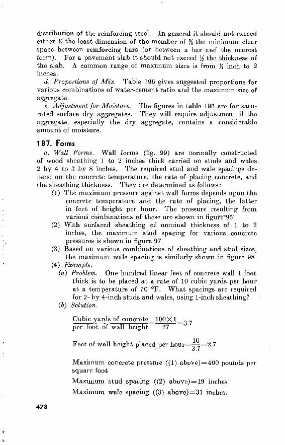
distribution of the reinforcing steel. In general it should not exceed either K the least dimension of the member of % the minimum clear space between reinforcing bars (or between a bar and the nearest form). For a pavement slab it should not exceed }£ the thickness of the slab. A common range of maximum sizes is from % inch to 2 inches.
d. Proportions oj Mix. Table 196 gives suggested proportions for various combinations of water-cement ratio and the maximum size of aggregate.
e. Adjustment for Moisture. The figures in table 196 are for satu- rated surface dry aggregates. They will require adjustment if the aggregate, especially the dry aggregate, contains a considerable amount of moisture.
T87. Forms a. Wall Forms. Wall forms (fig. 99) are normally constructed
of wood sheathing 1 to 2 inches thick carried on studs and wales 2 by 4 to 3 by 8 inches. The required stud and wale spacings de- pend on the concrete temperature, the rate of placing concrete, and the sheathing thickness. They are determined as follows:
(1) The maximum pressure against wall forms depends upon the concrete temperature and the rate of placing, the latter in feet of height per hour. The pressure resulting from various combinations of these are shown in figure"96'.
(2) With surfaced sheathing of nominal thickness of 1 to 2 inches, the maximum stud spacing for various concrete pressures is shown in figure 97.
(3) Based on various combinations of sheathing and stud sizes, the maximum wale spacing is similarly shown in figure 98.
(4) Example. (а) Problem. One hundred linear feet of concrete wall 1 foot
thick is to be placed at a rate of 10 cubic yards per hour at a temperature of 70 °F. What spacings are required for 2- by 4-inch studs and wales, using 1-inch sheathing?
(б) Solution.
Cubic yards of concrete 100X1 ^ y per foot of wall height 27
Feet of wall height placed per hour=—=2.7 O • l
Maximum concrete pressure ((1) above) = 400 pounds per square foot
Maximum stud spacing ((2) above) = 19 inches
Maximum wale spacing ((3) above)=31 inches.
478

i-í □.
— CO
"oK CO Lu
IO o
fO S
OtOt^tOU1) fO OJ
anOH U3d 133J NI SNIOVId dO 31Vd
479 533506o—60 31
Fig
ure
96
. M
axim
um
concr
ete p
ress
ure
s a
ga
inst
wa
ll fo
rms.

48
0
' ' - -J-' -73^ '•••'V t i-'^' •; '*.•
labte Wo. Cement Mix Proportions With flue sand—fineness modulus 2.20-2G0
Maximum size of
aggregate (luchos)
Water (gal- lons per sack of cement)
% 1
iH 2
% 1
VA 2
3A 1
VA 2
3A 1
VA 2
3A 1
1A 2
5A 5'A 5lA 5'A
Water (gal- lons per cubic yard of con-
crete)
VA 5'A 5A
5A
38 37 35 33
38 37 35 33
38 37 35 33
38 37 35 33
38 37 35 33
Cement (sacks per cubic yard
of concrete)
7. 6 7. 4 7. 0 0. 0
6. 9 6. 7 0. 4 6. 0
6. 3 6. 2 5. 8 5. 5
5. 9 5. 7 5. 4 5. 1
5. 4 5. 3 5. 0 4. 7
Fine awegutc (percent of total
aggregate)
43 38 34 31
44 39 35 32
45 40 30 33
40 41 37 34
47 42 38 35
Fine aggregate (pounds per sack
of cement)
170 100 150 150
Coarse aggregate (pounds per sack
of cement)
195 180 175 175
225 205 200 200
245 230 225 225
280 255 250 250
230 255 300 335
250 285 320 370
275 305 355 400
288 330 380 430
315 355 410 465
Fine aggregate (pounds per
cubic yard of concrete)
1, 290 1, 185 1, 050
990
1, 345 1,205 1, 120 1, 050
1,420 1, 270 1, 160 1, 100
1, 445 1, 310 1, 215 1, 150
1, 510 1, 350 1, 250 1, 175
Coarse aggregate (pounds per
cubic yard of concrete)
1, 750 1, 890 2, 100 2, 210
1, 725 1, 910 2, 050 2, 220
1, 730 1, 890 2, 060 2, 200
1, 700 1,880 2, 050 2, 195
1, 700 1,880 2, 050 2, 185
Yield (cubic feet of concrete per sack of cement)
3. 56 3. 65 3. 80 4. 09
3. 91 4. 03 4. 22 4. 50
4. 29 4. 36 4. 66 4. 91
4. 58 4. 74 5. 00 5. 30
5. 00 5. 10 5. 40 5. 75

481 %
1
i'A 2
VA
VA VA VA
38 37 35 33
5. 1 4. 9 4. 7 4. 4
48 43 39 3 G
300 285 275 275
330 380 430 495
1, 530 1, 400 1, 290 1, 210
1, 680 1, 860 2, 020 2, 180
5. 30 5. 51 5. 75 6. 14
3/4 1 VA 2
38 37 35 33
4. 8 4. 6 4. 4 4. 1
49 44 40 37
330 315 305 310
345 400 455 525
1, 585 1, 450 1, 340 1, 270
1, 655 1, 840 2, 000 2, 150
5. 63 5. 87 6. 14 6. 59
Ji 1
VA 2
38 37 35 33
7. 6 7. 4 7. 0 6. 6
45 40 36 33
180 165 160 160
220 250 290 325
1, 370 1, 220 1, 120 1, 055
1, 670 1, 850 2, 030 2, 140
3. 56 3. 65 3. 86 4. 09
% 1
iH 2
5'A 5'A 5i/2
5'A
38 37 35 33
6. 9 6. 7 6. 4 6. 0
46 41 37 34
205 190 185 185
240 275 315 360
1, 415 1, 270 1, 185 1, 110
1, 655 1, 840 2, 015 2, 160
3. 91 4. 03 4. 22 4. 50
y* 1
VA 2
% 1 VA
2
6/2 6/2 6'A 6'A
38 37 35 33
38 37 35 33
6. 3 6. 2 5. 8 5. 5
47 42 38 35
235 215 210 210
265 295 345 390
1, 480 1, 335 1, 220 1, 155
5. 9 5. 7 5. 4 5. 1
48 43 39 36
255 240 235 235
280 320 370 415
1, 505 1, 370 1, 270 1, 200
1, 670 1, 830 2, 000 2, 145
1, 650 1, 825 2, 000 2, 120
4. 29 4. 36 4. 66 4. 91
4. 58 4. 74 5. 00 5. 30

48
2
Maximum size of
aggregate (inches)
Water (gal- lons per sack of cement)
% 1
VA 2
% 1
IK 2
K 1
IK 2
3A 1
IK 2
7/ 7K 7K 7K
51/ 5K
Water (gal- lons per cubic yard of con-
crete)
38 37 35 33
38 37 35 33
38 37 35 33
38 37 35 33
Table 106. Cement Mix Proportions—Continued With fine sand—fineness modulus 2.20-260
38 37 35 33
Cement (sacks per cubic yard
of concrete)
5. 4 5. 3 5. 0 4. 7
5. 1 4. 9 4. 7 4. 4
4. 8 4. 6 4. 4 4. 1
7. 6 7. 4 7. 0 6. 6
6. 9 6. 7 6. 4 0. 0
Fine aggregate (percent of total
aggregate)
49 44 40 37
50 45 41 38
51 40 42 39
47 42 38 35
48 43 39 36
Fine aggregate (pounds per sack
of cement)
290 270 265 265
315 300 290 290
345 330 320 325
185 175 170 170
215 200 195 195
Coarse aggregate (pounds per sack
of cement)
305 340 395 450
315 365 415 480
330 385 440 510
210 240 280 315
230 265 305 350
Fine aggregate (pounds lier
cubic yard of concrete)
1, 565 1, 430, 1, 325 1, 245
1, 605 1, 470 1, 365 1, 275
1, 660 1, 520 1, 410 1, 330
1, 370 1, 295 1, 190 1, 120
1, 480 1, 340 1, 250 1, 170
Coarse aggregate (pounds per
cubic yard of concrete)
1, 650 1,'800 1, 975
'2, 120
1, 605 ' 1, 790 1„950 2, 110
1, 585 1, 770 1, 935 2, 090
1, 595 1, 775 1, 960 2, 080
1, 585 1, 775 1, 950 2, 100
Yield (cubic feet of concrete lier sack of cement)
5. 00 5. 10 5. 40 5. 75
5. 30 5. 51 5. 75 6. 14
5. 63 5. 87 6. 14 6. 59
3. 56 3. 65 3. 86 4. 09
3. 91 4. 03 4. 22 4. 50

48
3
H 1
1/2 2
3A 1
ijí 2
38 37 35 33
6. 3 6. 2 5. 8 5. 5
49 44 40 37
245 225 225 220
255 285 335 380
1, 540 1, 395 1, 305 1, 210
1, 610 1, 770 1, 945 2, 090
4. 29 4. 36 4. 66 4. 91
C’A 6A
6A 6'A
38 37'
35 33
5. 9 5. 7 5. 4 5. 1
50 45 41 38
265 250 250 250
265 310 355 405
1, 560 1, 425 1, 350 1, 275
1, 560 1, 765 1, 920 2, 065
4. 58 4. 74 5. 00 5. 30
^4 1
I/2 2
38 37 35 33
5. 4 5. 3 5. 0 4. 7
51 46 42 39
300 280 270 280
290 330 385 435
1,620 1,485 1, 350 1, 315
1, 565 1, 750 1, 925 2, 045
5. 00 5. 10 5. 40 5. 75
% 1
2
7/2
7A 7A 7A
38 37 35 33
5. 1 4. 9 4. 7 4. 4
52 47 43 40
330 310 305 305
300 355 400 465
1,685 1,520 1, 435 1, 340
1, 530 1,740 1, 880 2, 045
5. 30 5. 51 5. 75 6. 14
% 1
iA 2
38 37 35 33
4. 8 4. 6 4. 4 4. 1
53 48 44 41
360 345 335 340
315 370 425 480
1, 730 1, 590 1, 475 1, 395
1, 510 1, 700 1, 870 2,010
5. 63 5. 87 6. 14 6. 59
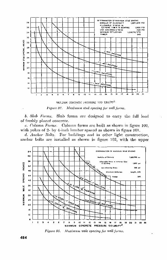
DETERMINATION OE MAXIMUM STUD SPACING
MODULUS OF ELASTICITY 1,600,000 PSI
ALLOWABLE STRESS IN EXTREME FIBER IN BENDING 1,800 PSI
UNIT SHEARING STRESS 200 PSI
MAXIMUM DEFLECTION LENGTH/270
TIMBER S4S
Í '»CH SNf
•NCH Sf1£4
T»i*G
'*CH S*£4T
"ING
>HCH SHEATHIHG
10 M 12 13 14 13 16 17 .8 19 20 21
MAXIMUM CONCRKTK PRESSURE 100 LBS/FT^
Figure!)?. Maximum slud spacing for wall forms.
b. Slab Forms. Slab forms arc designed to cany the full load of freshly placed concrete.
c. Column Forms. Column forms are built as shown in figure 100, with yokes of 2- by 4-inch lumber spaced as shown in figure 101.
d. Anchor Bolts. For buildings and in other light construction, anchor bolts arc installed as shown in figure 102, with the upper
DETERMINATION OF MAXIMUM WAlE SPACING
Modulut of EToiticiiy 1.600,000 pn
Atlpwobl« 5tr*u m extreme fiber in bending 1,800 pi
200 pil Unii Sheering Streit
- 48 Mex Deflection length /270
°S.
Id"
'»O
1*1*0 w
7 6 9 10 II 12 13 14 19 16 17 18 19 20 21 22 23
MAXIMUM CONCRETE PRESSURE I00LBS/FT2
Figure 98. Maximum wale spacing for wall forms.
484

■SHEATHING
WALES
STUD^ GRADE NAILS ✓-STUD
SHEATHING
O
A STRUT
V V
BRACES WIRE
r~~
■ '■ f. - ■ ¿::A jj
Figure 99. Wall forms and braces.
part of each enclosed in a 6-incli length of pipe or sheet-metal tubing to permit a slight lateral adjustment in bolt positioning.
e. Steel Pavement Forms. (1) Standard steel pavement forms are rapidly and accurately
set and should be used when obtainable. They are made
£
YOKES
0 ® Figure 100. Column forms.
485

LARGEST DIMENSION OF COLUMN IN INCHES oj
HEIGHT 16" 18 20 24” 28 30 32" 36
10
I I I 2 13'
I 5 16 I 7'
I 8 19 20
=-- K>
°J EXAMPLE: TO FIND THE YOKE SPACING FOR A 12-FOOT COLUMN THE LARGEST DIMENSION OF WHICH IS 16 INCHES, READ UP FROM 12-FOOT HEIGHT IN THE COLUMN HEADED 16 INCHES. YOKES ARE SPACED AT 21 INCHES, 29 INCHES, 30 INCHES AND 31 INCHES.
Figure 101. Yoke spacing for various sizes and heights of columns.
of %6-inch steel plate in sections 10 feet long. Forms for slab thicknesses of 6, 7, 8, 9, 10, and 12 inches can normally be obtained in the zone of interior. The usual base-plate width is 8 inches. The base-plate width should be equal to or greater than the face depth. Locking plates rigidly join the ends of the sections. Throe steel stakes, 1 inch in diameter, per 10-foot section of form are required.
(2) After the stakes are driven, the form is set true to line and grade and clamped to the stakes by special splines and wedges. Forms are set on the subgrade ahead of the paver
486

TEMPLATE
PIPE SLEEVE m
ANCHOR BOLTS
> "7 \
ïïm 0i ■lil
v.\ i 4 P * e ¿ w iff v ^
i Ê á iS
A & <1 ^ -P y * 4 * 4 A ¿4 v *
_£L_
PIPE SLEEVE
t ANCHOR BOLT FORM TEMPLATE
Figure 102. Installation of anchor bolts.
and must be left in place for at least 24 hours after the con- crete is placed.
(3) The forms must be oiled just before the concrete is placed. After a form is completely oiled, the top side or traction edge must be wiped free of oil.
(4) The forms are removed as soon as practicable, cleaned, oiled, and stacked in neat piles ready for reuse.
Section IV. BITUMINOUS CONSTRUCTION MATERIALS
188. Bituminous Materials Table 197 lists the principal asphalt and tar products used in paving,
with their source, form in which marketed, grade designation, temper- ature of application, and other data.
189. Bituminous Surface Treatment Table 198 gives the gradation requirements for aggregates. Tables
199 and 200 give the quautities of aggregate and bitumen for single- surface and double-surface treatments, respectively.
487

48
8
Table Î97. Bituminous Materials
Material Sourou Form Grade des- ignation
Temperature of application
Spraying (° t\)
Mixing (°F.)
Kemarks
Rapid curing
Cutback asplialts
(RC and MC).
Product of refining
crude petroleum
oils containing
asphalt.
Liquids, asphalt resi-
dues fluxed with
more volatile petro-
leum distillates.
KC-0
JlC-1 UC-2
uc-a RC-4
RC-5
50o-120°
8a°-15Ü0
100o-175°
15Qo-200° 175o-250°
2U0°-275o
50o-12U°
80o-125°
80o-150° 1250-175°
150o-200°
1750“225°
Naphtha or gasoline (highly volatile), evaporating quickly and
leaving asphalt-cement binder. Permits early use of surface.
Inflammable. Keep open flame away from storage tanks and drums.
Medium curing
MC-0 MC-1 MC-2
MC-3 MC-4 MC-5
50o-12U° 80o-150°
lU0°-20Uo
1750-25u°
200°-275° 225°-2750
50o-12Ü° 8U°-15U0
10Uo“200°
150o-20U° 1750-225° 200o-250°
Kerosene (less volatile) does not evaporate so quickly and cures
more slowly than RC types. Inflammable. Keep open flame away from storage tanks and drums.
Slow curing
Asphalt road oils
(SC). Products of refining
crude petroleum
oils containing
asphalt.
Liquids, low volatile oils left or blended with asphalt resi- dues near end of refining process.
SC-0
SC-l SC-2
SC-3 SC-f SC-5
50o-120o
80o-200°
150o-200° 175o-250° 175o-250°
2U0°-275o
50o-120° 80o-200°
150o-200° 175o-250°
1750-25U° 200o-275°
Slow curing.

48
9
Asphaltic cements (AC) or paving asphalts.
Powdered asphalt
(PA).
Asphalt emulsions (AE).
Semiliquids or solids..
Hard and solid asphalts ground to powder.
Asphalt cements in
water with an emulsifying agent.
Liquids.
40-50 ' 50-60 i
00-70 1
70-80 ' 85-100 ' 100-120 1
120-150 1
150-200 1
200-300 1
275o-3ô0°
275o-350°
2750-325°
200o-275°
Rapid, medium, and slow setting
RS-1
MS-l MS-2
MS-3 SS-1 SS-2
50o-140° 50o-140°
Penetration 40 to 100 used for crack and joint fillers. Penetrations
70 to 300 used for plant mixes, penetration macadam, and sur- face treatment. Comparable grades, Federal Specification SS_A-706b: 50-60 penetration, AP-5; 85-100 penetration, AP-3;
100-120 penetration, A P-2; 120-150 penetration, AP-1.
Used with SC oils to produce extra tough road surfaces.
Freezing destroys emulsion, penetration, and surface treatments.
Road and plant mixes with coarse aggregate. Road and plant
mixes with fine aggregate. Grades and typical uses of asphalt emulsions under Federal Specification SS-A-674a are as follows: Grade I, Surface treatments, seal coats. Grade II, Open- graded coarse aggregate mixed-in-place. Grade III, Summer
use in bituminous concrete mixtures for repair work. Grade IV, Winter use in bituminous concrete mixtures for repair work. Grade V, Penetration macadam and surface treatments.
Grade VI, Fine aggregate mixes in which a substantial quantity of aggregate passes ^-inch sieve and a portion may pass a No. 200 sieve.
. Penetrations of 100, 120, 150, 200, and 300 show Increasing softness of fluidity. Penetrations of 85, 70, 60, 50, 40, and so on, showing increasing hardness or sohdity road oil
SC5 (with high viscosity) and the softest paving asphalts both have penetrations of about 200.
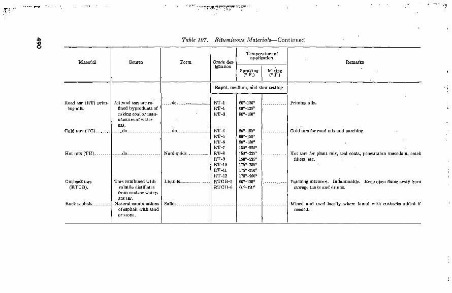
490
Table 197. Bituminous Materials—Continued
Material Source Form Grade des- ignation
Temperature of application
Spraying (° F.)
Mixing (° F.)
Road tar (RT) prim- ing oils.
Cold tars (TC).
Hot tars (TH).
Cutback tars (RTCB).
Rock asphalt..
All road tars are re- fined byproducts of coking coal or man- ufacture of water gas. do
.do..
Tars combined with volatile distillates from coal- or water- gas tar.
Natural combinations of asphalt with sand or stone.
.do..
.do..
Nonliquids-
Liquids.
Solids-
Rapid, medium, and slow setting
RT-1 RT-1 RT-3
RT-i RT-5 RT-6 RT-7 RT-8 RT-9 RT-10 RT-11 RT-12 RTCB-5 RTCB-G
60o-125° 60o-125° 80o-150°
80o-150o
8üo-150° 80°-150° 150o'225° 150o-225° 150o“225° 175o-250° 175°-250° 175o-250° G0°-120o
6ü0-12U°
Remarks
Priming oils.
Cold tars for road mix and patching.
Hot tars for plant mix, seal coats, penetration macadam, crack fillers, etc.
Patching mixtures. Inflammable. Keep open flame away from storage tanks and drums.
Mined and used locally where found with cutbacks added if needed.

Table 198. Gradation Requirements ¡or Aggregates for Bituminous Surface Treatments
Percent passing each sieve (square opening) by weight
Sieve designation
lJ-2-ineh_ 1-inch. %-inch.. J^-ineh.. %-inch. _ No. 4 No. 8... No. 10-- No. 16.. No. 50-. No. 100.
Gradation designations
No. 1
100 90-100 40-75 15-35 0-15 0-5
No. 2
100 90-100 20-55 0-15 0-5
No. 3
100 90-100
20-55 0-10 0-5
No. 4
100 90-100 40-70 0-15 0-5
No. 5
100 90-100 40-75 5-25 0-5
No. 6 1
100 85-100 10-30 0-10
No. 7 i
100 85-100 10-40
0-10
No. 8 1 No. fl i
100 50-100 0-5
100 95-100
45-80 5-30 0-8
i Clean sand may be used instead of crushed aggregates.
Table 199. Quantities of Aggregate and Bitumen for Single Surface Treatments
o
Material
Aggregate- Bitumen..
Unit of measurement
Pounds per square yard.. Gallons per square yard..
No. 2
35-45 0. 35-0. 45
Gradation designations
No. 3
35-45 0. 35-0. 45
No. 4
25-35 0. 25-0. 35
No. 6
25-35 0. 25-0. 35
No. 6
15-25 0. 15-0. 25
No. 8 No. 9
10-20 0. 10-0. 20
10-15 0. 10-0. 15

Table 200. Quantities of Aggregate and Bitumen for Double Surface Treatments
Gradation designations Bitumen (gallons per square yard),
first appli- cation
Aggregate (pounds per
square yard), first spreading
Bitumen (gallons per square yard),
first spread- ing
Aggregate (pounds per
square yard), second spreading
No. 1_ No. 4- No. 2- No. 6_ No. 4_ No. 7.
0. 45-0. 55
0. 40-0. 50
0. 35-0. 45
45-55
40-50
35-45
0. 2-0. 3 15-25
0. 2-0. 3
0. 2-0. 3
15-25
15-25
190. Gradation Control and Bituminous Content
Table 201 gives recommended limits for gradation control, and suggested bituminous content for each gradation, for asphaltic surface courses. Tables 202, 203, and 204 give similar data for asphaltic binder courses, asphaltic base courses, and tar mixes.
Section V. SOILS 191. General
For the control of soils in military construction, see TM 5-541. For data on soil classification and classification tests, the properties and engineering characteristics of soils, and soil surveys, see FM 5-250.
192. Soil Classification
Figure 103 gives the Unified Soil Classification system.
193. Identification of Soils Figure 104 gives a summary of identification procedure, using
laboratory test results.
194. Pertinent Characteristics of Soils Figure 105 summarizes the characteristics of soils which are per-
tinent to road and airfield construction. Figure 106 gives similar data pertaining to embankment and foundation construction.
Section VI. MISCELLANEOUS BUILDING MATERIALS AND HARDWARE
195. Wallboard, Insulation: Substitutes Nomenclature, sizes, types and logistical data are given in table
205.
492
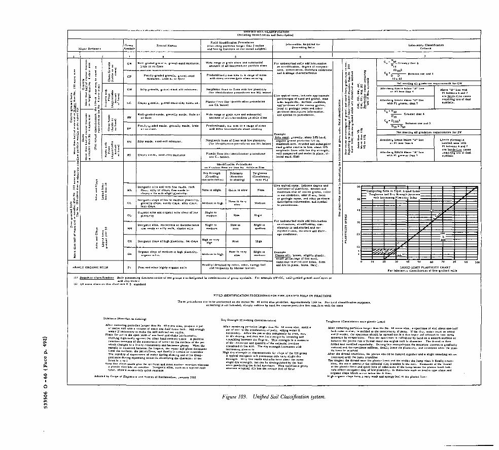
533506 0 -
60
(Face p
. 492)
UNIFIED SOIL CLASSIFICATION (Including Identilieadon and Description)
Major Divisions Croup
Symbol i Typical Names
Field Ideadflcatlon Procedures (Eseiuding partie!«» Isrger than 3 inches and basing (rsctlons on estimated weights)
Iniormstion Required (or Describing Soils
Laboratory Cisssi/icsüon
II.-
Ü
£l| 3 S,
S 1 Í I
■5 ^ V E
I :
es and substantial tedíate particle sise
ai9
M J
Silty gravels, gravel-sand-sllt mixtur« Nonplasuc fines or fines with low plasticity (for identification procedures see ML below
Clayey gravels, gravel*sand*clay mixture Plastic fines (for identification procedure see CL below)
Well-graded aands, gravelly sands, little
J S ;
all S52
Wide range in grain site and substantial amounts of all Intermediáis particle slat
Poorly-graded sands, gravelly sands, little
Silty sands, sand-silt mixture
: s S 5 : ; s s 1J
Nonplastic fines of fines with low plasticity (for Identification procedures see ML below)
or undisturbed soils add information on stratification, degree of compact- ness, cementation, moisture condition! and drainage characteristics
Give typical name, indicate approximil percentages of sand and gravel, maa sise, angularity, surface condition, and hardness of the coarse grains, local or geologic name and other pertinent descriptive information, and symbol in parentheses.
Example _SlUy_sa£id. gravelly, ebout 20ft herd,
angular gravel par&cles 1/2-in. maximum siae, rounded and subangulai
t lift
Clayey sands, sand-clay mixt
nonplastic fines with low dry strength, well compacted and moist in place, al- luvial sand, (SM)
Dry Strength (Crushing
:harecte rlsties)
Is I " 5 2
Inorganic silts and very fine sands, t flour, silty or clayey fine sands or clayey silts with alight plasticity.
Inorganic clays of low to medium plasticity, gravelly clays, sandy clays, silty clsys. Medium to high
Organic silts and c plasticity
rganic silty clays of low
Inorganic silts, micaceous or diatomaceous fine sandy or silty soils, elastic silts
Inorganic clays of high plasticity, fat clays
Organic clays of medlui to high plasticity, Medium to high
Dilatan cy (Reaction to shshing)
Toughness (Consistency
HIGHLY ORGANIC SOILS Peat and other highly organic Readily identified by color, odor, spongy feel
and frequently by fibrous textura.
Give typical name, indicate degree and character of plasticity, amount and maximum siae of coarse grains, color m wet condition, odor If any, local or geologic name, and other pertinent deacrlptive information, and symbol In parentheses.
For undisturbed soils add information on structure, stratification, con- sistency in undisturbed and re- molded elate», moieture end drain- age conditions,
Clayey slit, brown, slightly plastic, small percentage of fine sand, numerous vertical root holes, firm and dry in place, loess, (ML).
. ts a o o E «o« e g. » S s 3
a 0. u 3 O O t
I S3 |¡ : Ei* ¿ES
S H
s£- S 5 °
izi ut Ä« T fi3-
S S. S Sa"
— Greater 10
(D JO)* - Between one and 3
Not meeting all gradaoon requirements for GW
Atlerbcrg limits ebove "A" line with PI greater than 7
Above "A" line with PI between 4 and 7 are borderbne cases requiring use of dual symbols.
tiling all gradation requirements for 5W
Limits plotting in hatched tone with PI between 4 and 7 are borderllne cases requiring use of dual
—Comparing Soils at Equal Liquid Limit—
Toughness and Dry Strength Increase — m with Increasing Plasticity Index _
LIQUID LIMIT PLASTICITY CHART For laboratory classification of Une-grained soils
(l) Boundary c)a«eiflceüoi z» Soils possessing character! with clay binde r
chart are U S standard
s of (wo groups are designated by combinations of group symbols. For example GW-GC, well-graded gravel.sand mixture
FIELD IDENTIFICATION PROCEDURES FOR FINE-GRADED SOILS OR FRACTIONS
These procedures are to be performed on the minus No 40 sisve sise particles, approximately 1/64 in. For field classification purposes, screening 1« not intended, simply remove by hand the coarse particles that interfere with the tests
Dilatancy (Rsai o shaking) Dry Slrsngth (Crushing characteristics)
After removing particles larger than No 40 eieve sice, prepare a pat of moist soli with a volums of about one-half cubic inch. Add enough water if necessary to make the soil soft but not sticky.
Place the pat in the open palm of one hand and shake horieontally, striking vigorously against the other hand several times A positive reaction conaists of the appearance of water on the suriace of the pat which changes to a livery consistency and becomes glossy When the sample is squeezed between the fingere, the water and gloss disappear irom the surface, the pat stiffens, and finally it cracks or crumbles The rapidity of appearance of water during shaking and of Its disap- psarancs during squeeung assist in Identifying the character of the fines in a soil
Very fine clean sands give the quickest and moat distinct reaction wherea a plastic clay has no reaction Inorganic sllta, such as a typical rock flour, show a moderately quick reaction
After removing particles larger than No 40 sieve sise, mold a pat of soil to the concietency of putty, adding water if necessary. Allow the pat to dry completely by oven, sun, or air drying, and then test its strength by breaking and crumbling between the finge re. This strength is a measure of the character and quantity of the colloidal fraction contained in the soil. The dry strength increases with increasing plesucity
High dry strength Is characteristic for clays of the CH group A typical inorganic silt possesses only very slight dry strength Silty fine sands and silts havs about the same slight dry strength, but can be distinguished by the feel when powdering the dried specimen. Fins sand feels gritty whereas a typical eilt has the smooth feel of flour
Adopted by Corps of Engin« u of Reclamation, January 1952
Toughness (Consistency near plastic limit)
After removing particles larger than the No. 40 sieve sise, a specimen of sio) about one-half inch cubo in else, la molded to the consistency of putty. If too dry, water must be added and if sticky, the specimen should be spread out in a thin layer and allowed to lose some moisture by evaporation. Then the specimen is rolled out by hand on a smooth surface or between the palms into a thread about one-eighth Inch in diameter The thread is then folded and rerolled repeatedly. During this manipulation the moisture content ts gradually reduced and the specimen stiffens, finally loses its plasticity, and crumbles when the plat- tic limit is reached
After the thread crumbles, the plecee should be lumped together and a slight kneading action conaaued until the lump crumbles
The tougher the thread near the plastic limit and ths suffer the lump when it finally crum- bles, the more potent is the colloidal clay fraction in the eoil. Weakness of the thread at the plastic limit and quick loss of coherence of the lump below the plastic limit inili- cals either inorganic clay of low pJaaticiry, or materials such at kaolin-type clay» and organic clays which occur below the A-line.
High organic clays have a very weak and spongy ieel at the plastic limit
Figure 103. Unified Soil Classification system.

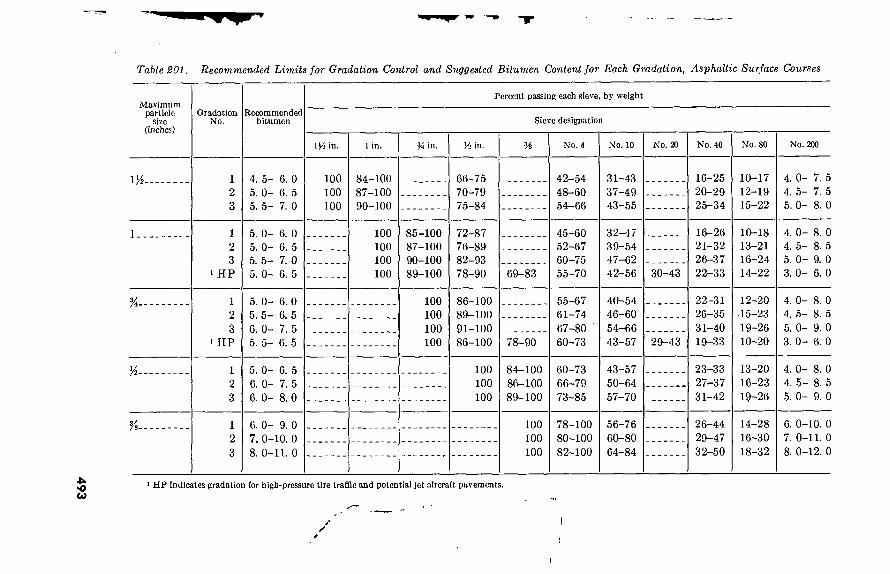
49
3
Table 201. Recommended Limits for Gradation Control and Suggested Bitumen Content for Each Gradation, Asphaltic Surface Courses
Maximum particle
size (inches)
Gradation No.
Recommended bitumen
Percent passing each sieve, by weight
Sieve designation
in. 1 in. V* in. H in. H No. 4 No. 10 No. 20 No. 40 No. 80 No. 200
iM- 4. 5- 6. 0 5. 0- 6. 5 5. 5- 7. 0
100 100 100
84-100 87-100 90-100
66-75 70-79 75-84
42-54 48-60 54-66
31-43 37-49 43-55
16-25 20-29 25-34
10-17 12-19 15-22
4. 0-
4. 5-
5. 0-
7. 5 7. 5 8. 0
1 2 3
> HP
5. 0- 6. 0 5. 0- 6. 5 5. 5- 7. 0 5. 0- 6. 5
100 100 100 100
85-100 87-100 90-100 89-100
72-87 76-89 82-93 78-90 69-83
45-60 52-67 60-75 55-70
32-47 39-54 47-62 42-56 30-43
16-26 21- 32 26-37 22- 33
10-18 13- 21 16-24 14- 22
4. 0- 8. 0 4. 5- 8. 5 5. 0- 9. 0 3. 0- 6. 0
%- 1 2 3
■ HP
5. 0- 6. 0 5. 5- 6. 5 6. 0- 7. 5 5. 5- 6. 5
100 100 100 100
86-100 89-100 91-100 86-100 78-90
55-67 61-74 67-80 60-73
40-54 46-60 54-66 43-57 29-43
22-31 26-35 31-40 19-33
12-20 15-23 19-26 10-20
4. 0- 8. 0 4. 5- 8. 5 5. 0- 9. 0 3. 0- 6. 0
5. 0- 6. 5 6. 0- 7. 5 6. 0- 8. 0
100 100 100
84-100 86-100 89-100
60-73 66-79 73-85
43-57 50-64 57-70
23-33 27-37 31-42
13-20 16-23 19-26
4. 0- 8. 0 4. 5- 8. 5 5. 0- 9. 0
6. 0- 9. 0 7. 0-10. 0 8. 0-11. 0
100 100 100
78-100 80-100 82-100
56-76 60-80 64-84
26-44 29-47 32-50
14-28 16-30 18-32
6. 0-10. 0 7. 0-11. 0 8. 0-12. 0
1 HP indicates gradation for high-pressure tire traffic and potential
y I
I

494
Table 202. Recommended Limits for Gradation Control and Suggested BitunlZV* Content for Each Gradation, Asphaltic Binder Courses
Maximum particle
size (inches)
Gradation No.
Recommended percent bitumen
2 in. iy¿ in. 1 in. in.
2 1 3. 5-5. 0 2 3. 5-5. 0 3 3. 5-5. 0
100 100 100
86-100 88-100 90-100
70-84 72-86 74-88
1
K
a
1 4. 0-6. 0 2 4. 0-6. 0 3 4. 0-6. 0
100 100 100
78-100 81-100 84-100
1 4. 0-6. 0 2 4. 0-6. 0 3 4. 0-6. 0
100 100 100
76-100 80-100 85-100
1 4. 5-7. 0 2 4. 5-7. 0 3 4. 5-7. 0
100 100 100
1 2 3
4. 5-7. 0 4. 5-7. 0 4. 5-7. 0
Percent passing each sieve, by weight
Sieve designation
Vi in. 96 in. No. 4 No. 16 No. 40 No. 80 No. 2UO
52-67 54-69 57-72
32-47 34-49 37-52
20-35 22-37 25-40
10-20 11-21 12-22
6-14 6- 14 7- 15
3-7 3-7 3-7
.56-73 59-77 63-80
35-51 39-55 42-58
23-38 27-42 31-46
11-21 13-23 15-25
6- 14 7- 15 8- 16
3-7 3-7 3-7
64-82 67-85 71-89
74-100 80-100 82-100
60-80 64-84 68-88
38-54 43-59 48-64
25-41 29-45 34-50
12-23 14-25 17-28
7- 10 8- 17
10-18
4-8 4-8 4-8
42-60 47-65 52-70
28-46 33-51 36-54
14-26 16-28 18-30
8-18 9-19
10-20
4-8 4-8 4-8
100 100 100
74-100 78-100 82-100
50-71 54-75 59-80
32-53 36-57 41-62
16-29 18-31 21-34
10-20 11-21 12-22
4-9 4-9 4-9
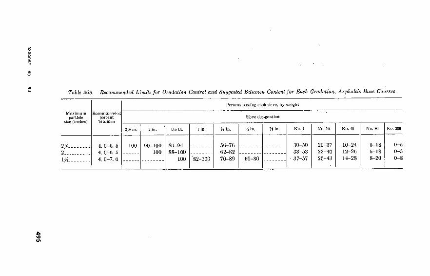
53
35
00
Ci o
CO to Table 203. Recommended Limits for Gradation Control and Suggested Bitumen Content for Each Gradation, Asphaltic Base Courses
Maximum particle
size (inches)
2K-
2...
IK-
Recommended percent bitumen
4. 0-6. 5 4. 0-6. 5 4. 0-7. 0
Percent passing each sieve, by weight
Sieve designation
2J4 in. 2 in.
100 90-100 100
US in.
80-94 88-100
100 82-100
in.
50-76 02-82 70-89
J.Ü in. lé in.
60-80
80-50 33-53 37-57
20-37 23-40 25-43
No. 40
10-24 12-26 14-28
No. SO No. 200
6-18 6-18 8-20
0-5 0-5 0-8
>o in

496
Table 204- Recommended Limits for Gradation Control and Suggested Bitumen Content for Each Gradation, Tar Mixes.
Maximum particle size, in.
Gradation No.
Recommended percent bitumen
Percent passing each sieve, by weight
Sieve designation
in. 1 in. % in. in. % in. No. 4 No. 10 No. 40 No. 80 No. 200
%-
K-
1 6. 0- 8. 5
2 7. 5- 9. 5
1 6. 5- 8. 5
2 7. 5-10
1 6. 5- 8. 5
2 8. 0-10
Surface Courses
100 100 100
85-100 85-100 90-100
100 100 100
85-100 85-100 90-100
100 100 100
60-75 65-82 73-85 70-85 75-90 80-93 82-100 85-100 90-100
40-58 47-65 54- 70 50-66 58-73 65-80 55- 70 65-80 70-84
25-43 32-48 37-55 35-50 40-55 50-65 35-50 45-60 50-66
10-20 15-25 18-30 15-25 20-30 25-35 13-24 18-29 24-35
5-13 8-15
10-20 7-15
10-18 12-20 7-14
10-19 12-21
2-8 4-10 4^10 4-10 4-10 6-10 4-10 4-10 6-10
Binder Course
VA- 4. 0- 5. 5 ! 5. 0- 6. 5
100 75-100 45-75 20-45 10-30 0-10 0-5
Base Courses
2y2. 2. 5- 5. 0 380-100 100
60-85
2..
1/2.
2. 5- 5. 0 2. 5- 5. 0
80-100 100
40-70 15-50 5-25 0-15
55-85 66-100
20-60 20-65
5-30 0-15 5-35 0-20
0-5
0-5 0-5
1 Stone or gravel. 2 Slag. 210(1 percent passing 2}4-inch sieve.

HIGHLY OBGANIC SOILS
VISUAL INSPICTION
0
LISS THAN S% MASSING NO 100
€«> A €g> I< S
NOT MIITINO GW BIQ
NOTK: > MÍAN» "MOBC THAN"
< Ml ANS "IK$S THAN"
OBI THAN HALT LAB GIB THAN NO 100 SIIVI
OBAVIL (G) MOBf THAN HALT COABSC «ACTION
LABOIB THAN NO 4 SIIVI
SANO (S) MOBI THAN HALT COABSI IBACTION
SMALLIB THAN NO 4 SIIVI
MOBI THAN 11% BASSINO NO 100
SHOW "A** UNI Bl < 4
[°*i 5^
S - 11% BASSINO NO 100
ASOVI "A" UNI Bl >7
~êï
BIQUIBIMIlhS SIMILAB TO THOM FOB "O" OBOUBS
FOB iW, Cw > 4
BOIOtBLINI BIQUIBING DUAL SYMBOLS
ASOVI "A" LINI Bl > 4 < 7
¿ES"!
•OBDIBilNI BIQUIBING DUAL SYMBOLS
•OBDIBLINI BIQUIBING DUAL SYMBOLS.
BINS OOAINID MOM THAN HALT SBULUB
THAN NO MO SIIVI
UQUID UMIT MLOW SO
BILOW 'A" LINI
ASOVI 'AM LINI
LIQUID UMIT ABOVI SO
BILOW "A" UNI
ABOVI "A" LINI
¿[SM] B
Figure 104. Idenlijicalion procedure fur soils using laboratory test results.
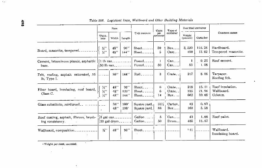
498
Table 205. Logistical Data, Wallboard and Other Building Materials
Board, masonite, tempered-
Cement, bituminous plastic, asphaltic base.
Felt, roofing, asphalt saturated, .15 lb, Type I.
Fiber board, insulating, roof board, Class C.
Sizes
Thick- ness
1 %"
Width
48” 48”
Length
96' 144'
1 lb can.. 50 lb can_
Vi"
36” 144'
48” 48” 48”
96” 120”
144”
Unit measure Units per
container
Sheet- Sheet .
Pound- Pound-
Roll.
Sheet- Sheet- Sheet-
50 5
1
50
6 6
14
Type of container
Box... Case.-
Can-__ Can.__
Crate..
Crate- Crate_ Box-_.
One filled container
Weight (pounds)
3, 520 450
1 53
217
218 235 662
Cubic feet
116. 28 13. 62
0. 23' 1. 08
8. 06
15. 21 21. 96 39. 05
Common names
Hardboard. Tempered masonite.
Roof cement.
Tarpaper. Roofing felt.
Roof insulation. VVallboard. Celotex.
Glass substitute, reinforced . 36” 48”
100'
198'
Roof coating, asphalt, fibrous, brush- ing consistency.
5 gal can 50 gal drum.
Wallboard, composition. 48” 96'
Square yard. Square yard.
33K 88
Carton. Box
43 160
0. 93 5. 58
Gallon. Gallon.
5 50
Can Drum.
43 485
1.08 11.67
Roof paint.
Sheet . >41 Wallboard. Insulating board.
1 Weight per sheet, uncrated.

533506 0 -
60 (F
ace p
. 49
8)
No.
Major Divisions
(1) (2)
Letts r
(3)
GRAVEL
AND
GRAVELLY
SOILS GM I
COARSE
GRAINED
SOILS
SAND
AND
SANDY
SOILS
SM j— ■
I U
SILTS
AND
CLAYS
LL 50
FINE
GRAINED
SOILS SILTS
AND
CLAYS
J. 50
HIGHLY ORGANIC SO!L£
Symbol
Hatching Colot
(4) (5)
t I
(6)
Well-graded gravels or gravel-oand mixtures, little or no fines
Poorly graded gravels or gravel-oand mixtures, little or no finco
Silty grávelo, gravcl-oand-oilt mixtures
Clayey gravels, gravcl-oand-clay
V/cll-,traded sands or gravelly sand’), httlL or no fines
Poorjy graded Lands or gravelly sand., Little or no fines
Silty sands, sand-silt mixtures
Clayey sands, sand-clcy mixtures
Inorganic silts and very line jando rock flour, silty or clayey fine oandj or clayey silts with slight plasticity
Inorganic clr.yo of low to medium plasticity, gravelly clays, sandy clays, silty clays, lean days
Organic silts and organic silt-days
of low plasticity
Inorganic silts, micaceous or diatom iccouo fine sandy or silty
Inorganic days of high plasticity, fat clays
Organic clays of medium to high plasticity, organic silts
Peat and other highly organic soils
Value as Foundation When Not Subject to
Frost ^rtlon
("
Excelles’
Good to cxccllcn
Good to excillc nt
Poor to very poor
Poor to very poor
Value as Base Di-
rectly under Bi- tuminous Pavement
(8)
Good
Fair to good
Poor to cot suitable
Not suitable
Not suitable
Not suitable
Not suitable
Not suitable
Not suitable
(9)
None to \
slight
None to % slight
Slight to medium
Slight to medium
Slight to
medium
None to y
slight
None to very .-light
Slight to
high
Slight to high
Slight t high
Medium to vc ry high
Medium to high
Medium t high
Medium to
vc ry high
Compressibility
and Expansion
(10)
Almost nono
Almost none
Almost none
Almost none
Very slight
Slight to modiui
Slight to mediu
Slight to medium
Medium to high
Drainage Characteristic!
(11)
Poor to practi- cally Impervious
Poor to practi- cally impervious
Poor to practi- cally impervious
Poor to practi- cally impervious
Practically impc rvious
Practically impc rvious
Very high
Practically impe rvious
Compaction Equipment
(12)
Crawler-type tractor, rubber- tired equipment, stecl-whccled roller
Crawler-type tractor, rubber- tired equipment, steel-wheeled roller
Rubber-tired equipment, checpofoot roller; dose con- trol of moisture
Rubber-tired equipment ehocpsfoot roller
Rubber-tired equipment, obeopefoot roller
Crawler-type tractor, rubber
tired equipment
Crawler-type tractor, rubber
Ured equipment
Rubber-tired equipment, shccpsfoot roller, close con- trol of moisture
Rubber-tired equipment, shccpifoot roller
Rubbor-tirod equipment,
shoepsfoot roller
Rubber-ured equipment, shLcpsfoot roller, close
Control of moisture
Rubber-tired equipment, ehocpsfoot roller
Rubber-tired equipment, sherp-foot roller
Shccpsfoot roilcr
Shcepsfoot roller
Sheopsfoot roller
Compaction not practical
Unit Dry Weight
Lb Pc r Cu Ft (13)
125-140
Field
(CBR) (14)
bubgrade Modulus
Lb Per Cu in. (15)
300 or more
on basis of Attcrberg limits; suffix d (e g , GMd) ' i greater than 28.
Column 3, Division oí GM, and SM groups into subdivisions of d and u are for roads and airfields only, subdivision when the liquid limit is 28 or less and the plasticity index is 6 or less, the suffix u will bo used when the liquid Umi Column 7, values are for subgradco and base courses except for base course directly under bituminous pavement. In column 8, the term ''«scellent" has been reserved lor base materials consisting of high quality processed crushed stone. In column 9, these soils are susceptible to frost as indicated under conditions favorable to frost action described in the text. In column 12, the equipment listed will usually produce the required densities with a reasonable number of passes when moisi
In some inot».«», .ovoral type, of .quipmet art 11.td, bcctuo variable .oil ehat.cteri.Ue. orlthta a jlvoo .oil 8roup may roquiro diff.roal equipment. lo .omc in.taocc.,
rmprÔe«^.d^.«^m.UTi^.1^JCo“.°*daulor material.. Stccl-»heelod roll... aro recommended for hard aoBular material, with limited line, or .croenlnj., Rubber-Bred
equipment is recommended for eofter materials subject to degradation, b. Finishing. Rubber-tired equipment is recommended for rolling during final shaping operations for most soils and processed materials.
ç. Equipment «... The lollowlaj ..... ol equipment are aecc.oary to e..ure the hlih dea.M.. required lor atrf.old oon.truetioo.
Rubhlr-ttm'd equipment '“^."^^”1«”«” o.^oMs” 000», wheel load. a. hlsh 0. 40, 000 lb may be nacea.ary to obtaut the required d.n.itie. for .ome moicpial. (bo.od on
Shoopalool'mllo^-^um^prOBOu^e‘(on 6-°to ^IZdq-ln. loo.) .0 be Ib oxeo., ol 250 pel and urn. pre..ure. a. high aa 650 pal may be noee..ary .0 obwtn U»
for .om. material.. The area ol lb. let .bould bo at loaat 5 per rout ol the total peripheral area ol the drum, uemg the diameter meaeured to the lacee of the leet. Column 13. unit dry weights are for compacted soil at optimum moisture content for modified AASHO compccuvc effort.
a moisture conditions and thickness of bit arc properly controlled.
Figure 105. Characteristics of soils pertinent to roads and airfields.


533506 0 -
60 (F
ace p
. 4
98
) N
o.
Major Divisions
(1) (2)
Letter
(3)
Symbol
Hatching Coloi
(4) (5)
Name
(6)
Value for Embankments
(7)
Permeability
Cm Per Sec
(8)
Compaction Characteristics
(9)
Std AASHO Max
Unit Dry Weight Lb Per Cu Ft
(10)
Value for
Foundations
(11)
Requirements for
Seepage Control
(12)
COARSE
GRAINED
SOILS
GRAVEL
AND
GRAVELLY
SOILS
I
1 Well-graded gravels or gravel-sand
mixtures, little or no fines Very stable, pervious shells
of dikes and dams
.10 -2
Good, tractor, rubber-tired,
steel-wheeled roller
125-135 Good bearing value Positive cutoff
Poorly-graded gravels or gravel-sand Reasonably »table, pervious shells of dikes and dams
Good, tractor, rubber-tired, steel-wheeled roller
Good bearing value Positive cutoff
Silty gravels, gravel-sand-silt mix-
tures Reasonably stable, not particu- larly suited to shells, but may
be used for impervious cores or
blankets
Good, with close control,
rubber-tired, shcepsfoot roller
Good bearing value Toe trench to none
Clayey gravels, gravel-sand-clay mixtures
Fairly stable, may be used for
impervious core
Fair, rubber-tired, sheepsfoot
rolle r Good bearing value
Well-graded sands or gravelly sands,
little or no fines Very stable, pervious sections, slope protection required
SAND
SM AND
SANDY
SOILS SC
Poorly-graded sands or gravelly
sands, little or no fines Reasonably stable, may be used in dike section with flat slopes
Silty sands, sand-silt mixtures Fairly stable, not particularly suited to shells, but may be
used for impervious cores or dikes
Clayey sands, sand-silt mixtures Fairly stable, use for impervious
core for flood control structures
Good, tractor Good bearing value Upstream blanket and
toe drainage or wells
Good, tractor Good to poor bearing
value depending on
density
Upstream blanket and
toe drainage or wells
Good, with close control,
rubber-tired, sheepsfoot roller
Good to poor bearing
value depending on
density
Upstream blanket and
toe drainage or wells
Fair, sheepsfoot roller,
rubber tired Good to poor bearing value
SILTS
AND
CLAYS
LL 50
FINE
GRAINED
SOILS
Inorganic silts and very fine sands,
rock flour, silty or clayey fine
sands or clayey silts with slight
plasticity
Poor stability, may be used for embankments with proper control
Good to poor, close control
essential, rubber-tired roller, sheepsfoot roller
95-120 Very poor, suscepti-
ble to liquefaction Toe trench to none
I Inorganic clays of low to medium
plasticity, gravelly clays, sandy
clays, silty clays, lean clays
Stable, impervious cores and
blankets k = 10"
to 10"
Fair to good, sheepsfoot
roller, rubber tired
Organic silts and organic silt-clays
of low plasticity
Not suitable for embankments 0-6
Fair to poor, sheepsfoot
roller
95-120 Good to poor bearing
Fair to poor bearing,
may have excessive
settlements
SILTS
AND
CLAYS
LL 50
I Inorganic silts, micaceous or
diatomaceous fine sandy or silty
soils, elastic silts
Poor stability, core of hydraulic
fill dam, not desirable in rolled fill construction
n-6 Poor to very poor, sheepsfoot
rolle r
Poor bearing
2 Inorganic clays of high plasticity,
fat clays
Fair stability with flat slopes,
thin cores, blankets and dike
sections
Fair to poor, sheepsfoot
roller Fair to poor bearing
4
Organic days of medium to high
plasticity, organic silts
Not suitable for embankments Poor to very poor, sheepsfoot
rolle r
65-100 Very poor bearing
HIGHLY ORGANIC SOILS Peat and other highly organic soils Not used for construction Compaction not practical Remove from foundations
Notes: 1. Values in columns 7 and 11 are for guidance only. Design should be based on test results. 2. In column 9, the equipment listed will usually produce the desired densities with a reasonable number of passes when moisture conditions and thickness of lift are
properly controlled.
3. Column 10, unit dry weights are for compacted soil at optimum moisture content for Standard AASHO (Standard Proctor) compactive effort.
Figure 106. Characteristics of soils pertinent to embankments and foundations.


196. Nails and Spikes a. Types and uses. See figure 107 for the sizes and uses of various
types of nails.
Type
Cut
Size Use
Nail 2d to 60d
An old type no longer used except in 8d size for flooring and in various sizes for special purposes. Square point permits it to penetrate with less splitting than wire nails. Tap- ered shank permits drawing of floor joints much tighter than with wire nails.
y Common Nail
Scaffold or Form Nail
nishing Nail
2d to 60d
Standard for cpncealed work, rough work, and most exposed exterior
' work. For work to be painted the head can be set and covered with putty. Better holding power than the finishing nail.
>fà"*to 4Î6"
For temporary use in scaffolds and concrete forms. Double head facili- tates withdrawal. Also used as a self-furring nail on exterior metal lath.
2d to 20d For wood trim and other interior work
for paint or varnish finish. The head is set below the surface leaving a small hole to be puttied.
-2d to 4d For lathing; wood loth, gypsum loth,
fiber lath, and interior metal lath.
Standard Head
Large Head
Barbed Roofing %" to 2" For the first felt layer of built-up.roof- Ing over wood sheathing.
Figure 107. Nails.
499

500
b. Wire-Nail Sizes, Wire Gages, and Number Per Pound.
Table 206. Wire-Nail Sizes, Wire Gages, and Number Per Pound
Size Length (inches)
Common
Gage No./lb.
Siding
Gage No./lb.
Finishing
Gage No./lb.
Flooring Fence
Gage No./lb. Gage No./lb.
2d.. 3d.. 4d__ 5d__ 6d_. 7d._ 8d._ 9d._ 10d_ 12d. 16d. 20 d. 30d. 40d. 50d_ 60d.
1
Pi 1/2
1/4
2
ay* 2/ 2/ 3 3/ 3/ 4 4H 5 5/2
6
15 14 12/ 12/ 11/ 11/ 10/ 10/ 9 9 8 6 5 4 3 2
876 568 316 271 181 161 106
96 69 63 49 31 24 18 15 11
15/ 14/ 14 14 12/ 12/ 11/ 11/ 10/
1, 010 635 473 406 236 210 145 132 94
16/ 15/ 15 15 13 13 12/ 12/ 11/ 11/ 11
10
1, 351 807 584 500 309 238 189 172 121
113 90 61
11
11
10
10
9 8 7 6
157 139 99 90 69 54 43 31
10 10
9 9 8 7 6 5
142 124 92 82 62 50 40 30
Note 1. To avoid splitting, nail diameters should not exceed / of the thickness of lumber to be mailed. Note 2. Gages in above table are U.S. Steel Wire Gage. Fractional gages are:
Oage...
Diameter, inches..
lOH
0.1314
1014
0.1278
1114 1214
■ 0.0985
1414 1514
0.0073

c. Standard Barbed Roofing Nails.
Size and length.
Gage. 13 12 12 12 11 11 10 10
Number per pound 714 469 411 365 251 230 176 151 103
d. Standard Round Spikes, Flat Head, Diamond Point.
Length (inches)-.
Gage
Number per pound
10d 12d
3M
38
16d
3H
30
20d
23
40d
13
50d 60d
Mo"
9
W
3K*
10"
w
2Ki
e. Nails and Spikes Stocked in Oversea Depots (Fed. Spec. FF-N-103 and FF-N-105) (SM 5-3). See table 207.
197. Wood Screws
The weight of flat-head bright wood screws, in pounds per gross, is given in table 208. The table also indicates the sizes manu- factured. Sizes stocked in oversea depots are in italics.
198. Staples
a. Wire staples, fence steel, galvanized, are stocked in oversea depots in two sizes, %-inch and 1%-inch, both of number 9 wire.
b. Cut-point staples (fig. 108) are furnished in five sizes for various cables and conductors.
199. Lag Screws
a. Dimensions. Diameters and threads per inch of lag screws are given in table 209; lengths of threaded portions of lag screws are given in table 210.
501

Table S107. Nails and Spikes Slocked in Oversea Depots
(Federal Specifications FF-N-103 and FF-N-105)
Remarks
Description Unit of issue
NAIL, BOX, GENERAL PURPOSE, wire, steel, smooth shank, diamond point, flat head, Fed FF-N-105, box nail type:
Cement coated finish: 2d, 1 in. Ig, 0.058 in. dia shank, 0.172 in. dia head 3d, lYs in. Ig, 0.063 in. dia shank, 0.188 in. dia head 4d, 1% in. Ig, 0.067 in. dia shank, 0.203 in. dia head 5d, 1% in. Ig, 0.072 in. dia shank, 0.219 in. dia head 6d, V/i in. Ig, 0.086 in. dia shank, 0.250 in. dia head 7d, 2% in. Ig, 0.086 in. dia shank, 0.250 in. dia head ' 8d, 2% in. Ig, 0.099 in. dia shank, 0.266 in. dia head 9d, 2% in. Ig, 0.099 in. dia shank, 0.266 in. dia head
. lOd, 2%-in. Ig, 0.113 in. dia shank, 0.297 in. dia head Protective finish, not applicable:
4d, 1J4 in. Ig, 0.080 in. dia shank, 0.219 in. dia head 5d, 1% in. Ig, 0.080 in. dia shank, 0.219 in. dia head 6d, 2 in. Ig, 0.099 in. dia shank, 0.266 in. dia head 7d, 2% in. Ig, 0.099 in. dia shank, 0.266 in. dia head 8d, 2% in. Ig, 0.113 in. dia shank, 0.297 in. dia head lOd, 3 in. Ig, 0.128 in. dia shank, 0.313 in. dia head
lb lb lb lb lb lb lb lb lb
lb lb lb lb lb lb
Expend- ability
Illustration No. Repair Category of
parts sup- issue port code
X X X X X X X X
5 5
2.5 5
2.5 5
2.5 5
X 2, 5
X X X X X X
2,5 5 5 5
2, 5 2, 5

503
NAIL, BOX, NAILING MACHINE, wire, steel, cement coated finish, Ref Dwg
Group 22, sections B, D, E, smooth shank, style 16, diamond point, style 7: Flat countersunk head, style 18, Fed FF-N-105, cement coated countersunk head
nail type: 3d, l/s in. Ig, 0.067 in. dia shank, 0.172 in. dia head 4d, 1% in. Ig, 0.020 in. dia shank, 0.203 in. dia head 5d, 1% in. Ig, 0.026 in. dia shank, 0.219 in. dia head 6d, 1% in. Ig, 0.092 in. dia shank, 0.234 in. dia head 8d, 23/s in. Ig, 0.113 in. dia shank, 0.266 in. dia head lOd, 2% in. Ig, 0.121 in. dia shank, 0.281 in. dia head 12d, 3>i in. Ig, 0.135 in. dia shank, 0.313 in. dia head 20d, 3% in. Ig, 0.177 in. dia shank, 0.375 in. dia head 30d, 4% in. Ig, 0.192 in. dia shank, 0.406 in. dia head 40d, 4% in. Ig, 0.207 in. dia shank, 0.438 in. dia head 60d, 3% in. Ig, 0.244 in. dia shank, 0.500 in. dia head
Flat head, style 14, Fed FF-N-105, cement coated standard, nail type: 2d, 1 in. Ig, 0.063 in. dia shank, 0.172 in. dia head 3d, lYs in. Ig, 0.067 in. dia shank, 0.188 in. dia head 4d, 1% in. Ig, 0.080 in. dia shank, 0.219 in. dia head 5d, iys in. Ig, 0.086 in. dia shank, 0.234 in. dia head 6d, 1% in. Ig, 0.092 in. dia shank, 0.250 in. dia head 7d, 2% in. Ig, 0.039 in. dia shank, 0.266 in. dia head 8d, 2% in. Ig, 0.113 in. dia shank, 0.281 in. dia head lOd, 2% in. Ig, 0.121 in. dia shank, 0.297 in. dia head
NAIL CASING, wire steel, Ref Dwg Group 22, sections B, D, E, smooth shank, style 18, diamond point, style 16, flat countersunk head, style 13, Fed FF-N-105:
4d, iy2 in. Ig 6d, 2 in.Ig 8d, 2y2 in. Ig
NAIL, CLOUT, cut, steel, Ref Dwg Group 22, sections B, D, E'j tapered shank, style 19, blunt point, style 2, flat head, style 14, Fed FF-N-103:
% in. Ig 1 in. Ig
lb lb lb lb lb lb lb lb lb lb lb
lb lb lb lb lb lb lb lb
lb lb lb
lb lb
X X X X X X X X X X X
X X X X X X X X
X X X
X X

50
4
Table 207. Nails and Spikes Stocked in Oversea Depots—Continued
(Federal Specifications FF-N-103 and FF-N-105)
Description
NAIL, COMMON, wire, steel, smooth shank, diamond point, flat head, Fed FF-N- 2d, 1 in. Ig
105:
3d, Di in. Ig 4d, iy2 in. Ig 5d, \% in. Ig 6d, 2 in. Ig 7d, 2% in. Ig 8d, 2% in. ig 9d, 2% in. ig lOd, 3 in. Ig 12d, 3% in. ig 16d, SYi in. Ig i 20d, 4in. Ig 30d, áy2 in. Ig 40d, 5 in. Ig 50d, 5}^in. Ig 60d, 6in. Ig Zinc coated finish: 4d, in. Ig 20d, 4in. Ig
NAIL, COMPOSITION ROOFING, wire, steel, zinc coated finish, Ref Dwg Group 22, sections B, D, E, barbed shank, style 1, diamond point, style 7, fiat head, style 14, Fed FF-N-103, roofing nail type:
Unit of issue
lb lb lb lb lb lb lb lb lb lb lb lb lb lb lb lb
lb lb
Expend- ability
X X X X X X X X X X X X X X X X
X X
Illustration No.
Remarks
Repair parts sup- port code
CatcRory of issue
2, 5 2, 4 2, 4
5 2.4
5
2, 4 5
4.8 4, 8 2, 4 2.4 2.4 4.8
2, 4 4, 8
1, 2 1

505
% in. lg 1 in. lg
NAIL, DOUBLE HEADED, wire, steel, Kef Dwg Group 22, sections B, D, E, smooth shank, style 16, diamond point, style 7, duplex head, style 11, Fed FF-N-105, duplex head nail type:
8d, 2Yi in. Ig. from under lower head to point, % in. Ig- between heads, 0.131 in. dia shank.
lOd, 2% in. Ig. from under lower head to point, in. Ig. between heads, 0.148 in. dia shank.
16d, 3 in. Ig. from under lower head to point, % in. Ig. between heads, 0.182 in. dia shank.
NAIL, DRIVE SCREW, wire, steel, Ref Dwg Group 22, sections B, D, E, screw shank, style 11, needle point, style 9, oval head style 43, 1% in. Ig, 0.177 in. dia. shank, Signode Co. or equal.
NAIL, FINISHING, wire, steel, Ref. Dwg. Group 22, sections B, D, E, smooth shank, style 11, needle point, style 9, oval head style 43, 1% in. Ig, 0.177 in. dia. shank, Signode Co. or equal.
NAIL, FINISHING, wire, steel, Ref. Dwg. Group 22, sections B, D, E, smooth shank, style 16, diamond point, style 7, brad head, style 2, Fed FF-N-105:
3d, 1% in. Ig 4d, iy2 in. Ig 6d, 2 in. Ig 8d, 2}i in. Ig lOd, 3 in. Ig '
NAIL, FOUNDRY, wire, steel, protective finish not applicable, Ref. Dwg. Group 2}i sections B, D, E, smooth shank, style 16, diamond point, style 7, flat head, style 14, 0.162 in. dia. shank, 0.500 in. dia. head, Fed FF-N-101:
1 in. Ig 2 in. Ig 3 in. Ig
lb lb
lb
lb
lb
lb
lb lb lb lb lb
lb lb lb
X X
X
X
X
X
X X X X X
X X X
2, 4 2,4
2
2
2
2 1,2 1,2
2 2
1,2 1,2 1,2

506
Table 208. Sizes and Weights of Wood Screws
Size
0 1 2 3 4 5 6 7 8 9
10 11 12
13 14 15 16 17 18 20 22 24 26 28 30
X
0. 024 . 037 . 052 . 070 . 092
0. 040 . 060 . 085 . 101
. 13
. 16
. 20
. 24
. 29
. 34
0. 07 . 10 . 13 . 16 . 20 . 25 . 31 . 37 . 44 .51 . 58 . 66
%
0. 09 . 12
. 15
. 19
. 25
. 30
. 37
. 44
. 52
. 60
. 69
. 79
. 90 1. 03
0. 13 . 17 . 22
. 29
. 36
. 43
. 56
. 61
. 71
. 82
. 93 1. 05 1. 18 1. 32 1. 47
0. 15 . 20 . 26 . 33 • 41 . 50 . 59 . 70 . 81 . 94
1. 07 1. 21
1. 36 1. 53 1. 71
0. 26 . 29 . 38 . 46 . 56 . 67 . 79 . 92
1. 07 1. 21 1. 37 1. 54 1.' 74 1. 92 2. 12 2. 34
0. 30 . 37 .48 . 59 . 72 . 85 . 99
1. 16 1. 34 1. 52 1. 72 1. 93 2. 15 2. 39 2. 65 2. 95 3. 50 4. 13 4. 78
iM
0. 44 . 56 . 68 .84 . 99
1. 17 1. 36 1. 56 1. 78 2. 01
2. 26 2. 54 2. 82 3. 13 3. 45 4. 10 4. 86 5. 65
0. 64 . 79 . 96
1. 15 1. 35 1. 57 1. 80 2. 07 2. 34 2. 63 2. 92 3. 25 3. 61 4. 00 4. 78 5. 60 6. 52
0. 73 . 90
1. 10
1. 32 1. 54 1. 78 2. 04 2. 35 2. 67 2. 99 3. 34 3. 73 4. 13 4. 53 5. 40 6. 35 7. 39
i'Á
1. 10 1. 23 1. 46 1. 71 2. 00 2. 32 2. 64 2. 97 3. 33 3. 72 4. 14 4. 58 5. 05 6. 03 7. 04 8. 26
2'A
1. 13 1. 37 1. 64 1. 93 2. 24 2. 59 2. 94 3. 33 3. 72 4. 16 4. 62 5. 13 5. 65 6. 76 7. 90 9. 13
25Í 3'A
2. 25 2. 63 3. 07 3. 53 4. 01 4. 53 5. 08 5. 65 6. 28 6. 95 7. 68 9. 13
10. 70 12. 50 14. 40
2. 57 3. 00 3. 48 4. 01 4. 57
5. 75
7. 10
8. 67 10. 40 12. 20 14. 15 16. 25 18. 40 21. 00
5. 14
6. 25
8. 09
9. 89 11. 80 13. 80 16. 20 18. 60 21. 25 24. 30
5. 80
7. 34
9. 04
11. 10 13. 40 15. 50 18. 15 20. 80 23. 75 27. 30
8. 60
10. 70
12. 90 15. 40 18. 30 21. 20
24. 40 27. 70 31. 80

Figure 108. Cut-point staples.
Table 209. Diameters and Threads Per Inch of Lag Screws
Diameter at root of thread, inches.
Diameter of pilot hole for threads, inches.
Lag screw diameters
H 7A 1
0. 173 0. 227 0. 265 0. 328 0. 371 0. 471 0. 579 0. 683 0. 780
Mo y* Mo
Threads per inch. 10 3'A
b. Sizes Stocked in Oversea Depots. (1) Standard lag screws, cone point: M- by 1-inch, %- by 4-inch,
by 2-inch, ){- by 4-inch, %- by 4-inch, and %- by 4-inch. (2) Gimlet point: black, %- by 3-inch; galvanized ji- by 4K-inch.
507

Table 210. Lengths of Threaded Portions of Lag Screws
Lag screw lengths, inches »
2 and and 2%_
3 and 3^___ 4 and 4J4--. 5 and 5}í — . 6 and 7 and 7)4-- 8 and 8)4--- 9 and 9>4--- 10
11 12 13 14 15 16
Lag screw diameters
IJi 1/2 2 2/ 3 3/2 4 4/ 5 5/
Mo
1/2 1% 2 2/ 3 3/2 4 4/2 5 5/
1/2 1/s 2 2/ 3 3/2 4 4/2
5 5/ 5/ 6
Me
1/ IJS 2 2/ 3 3/ 4 4/ 5 5/ 5/ 6
1/
1% 2 2/ 3 3/ 4 4/ 5 5/ 5/ 6 6/2 7 7/ 8
H H %
1/2 1/4 2 2/2 3 3/ 4
0/4
5/2 0
6/ 7 7/ 8
2 2/2 3 3/ 4 4/ 5 5/
5/ 6 6/2
7 7/ 8
2 2/ 3 3/ 4 4/2 5 5/
5/ 6 6>'2
7 71/ ' >2
8
2 2/ 3 3/ 4
4/ 5 5/ 5/ 6 6/ 7 7/ 8
1 Measured from underside of head to point.
200. BoltS/ Machine, American Standard Regular Table 211. Bolt Sizes and Threads
Bolt (inches) Number
of threads per inch 1
Diameter at root
of thread (inches)
Area at root of thread (square inches)
Short diameter of square
head (inches)
Short diameter
of nut (square or hexagon) (inches)
Height of nut (inches)
Z-
/s-
1--
1/8-
1/-
l/e-
1/-
1/s-
IJi- l/8- 2..
2)4- 2/2-
2%.
3.-
20 16 13 11 10
9 8 7 7 6 6
0. 185 . 294 . 400 . 507 . 620 . 731 . 838 . 939
1. 064 1. 158 1. 283
1. 490
4/ 4/ 4 4 4
1. 711 1. 961 2. 175 2. 425 2. 675
0. 027 . 068 . 126 . 202 . 302 . 419 . 551 . 693 . 890
1. 054 1. 294
1. 744
2. 300 3. 031 3. 716 4. 619 5. 621
3/s 9/o
l/s 1/0
1/2
1% 1Z 2/6
2)4 2/0
2/s 2'M, 3 3/s 3/4 4/s 4/
Ze
% ■H
l
1/ l/c 1/2 I'/e
1/ 2/o 2/ 2/0
2% 2'Zo 3/s 3/ 3/
4/ 4/s
Zo
Ze
Z
1 1/8 I/ I/O
1/8
I/
1Z 2 2/ 2/2
2/
3
> American National Form screw threads.
508

201. Manila Rope a. Weight and Strength. Table 212 shows the unit weights and
breaking strengths of the most commonly used sizes of manila rope (natural color, three-strand, oil-treated).
b. Sheave Diameters. Within the range of sizes shown in table 212, sheave diameter should be not less than eight times the diameter of the rope.
Tabic 212. Manila Rope
%-
Ws-
1/2-
2..
2/4.
2/-
2%. 3_-
Circumferencc (inches) Feet per pound
50. 0 34. 5 24 13. 3
7. 5 6. 0
4. 54 3. 71
Breaking strength (pounds)
600 1,000 1, 359 2, 650 4, 400 5, 400 6, 500 7, 700 9, 000
202. Sand, Gravel, Crushed Rock Tables 213 through 218 give data on sand, gravel, and crushed
rock used as construction materials'. ' ' ' '
Table 213. Linear Feel of Spread of Gravel and Crushed Rock To Produce l-hich Thickness
Width, feet Thickness
Inches Condition 1
Linear feet of spread 1 cu. yd.
10- (Loose [Compacted.
32. 4 25. 9
1 Ratio of loose thickness to compacted thickness assumed to be 1.25 to 1.
Example: Length of spread for 2[(-cubic yard truckload of gravel to produce 4-inch compacted thick- ness 22 feet wide is:
L=25.9X^X2.5X)(=7.3 feet.
509

Table 2Ut. Cubic Yards, Loose Measure, Granel or Crushed Rock Required Per Linear Unit of Road to Produce 1-Inch Thickness
Width in feet Condition > Length of rood section
100 ft. 100 yd. 1 mile
10- Loose Compacted.
3. 09 3. 86
9. 26 11. 57
162. 9 203. 6
1 Ratio of loose thickness to compacted thickness assumed to be 1.25 to 1.
Example: Quantity required for 4-inch compacted course on 350 yards of road 22-feet wide is:
22 4 350 11.57X^0X^X^00=356.4 cubic yards, loose measure.
Table 215. Square Yards per Hundred Running Feel, per Hundred Yards, and Per Mile for Various Surface Widths .
Width in feet Number of square yards—
Per 100 ft. Per 100 yd. Per mile
9- 10. 12.
16.
18. 20.
22.
100. 0 111. 1 133. 3 177. 8 200. 0 222. 2 244. 4
300. 0 333. 3 400. 0 533. 3 600. 0 666. 7 733. 3
5, 280 5, 867 7, 040 9, 387
10, 560 11, 734 12, 907
Table 216. Pounds of Aggregate Required per Square Yard for Various Thicknesses of Compacted Layers
Weight of 1 eu. yd. dry loose aggregate, pounds
2,100.
2,200.
2,300. 2,400. 2,500. 2,600. 2,700. 2,800. 2,900. 3,000.
Thickness of compacted layer 1
in.
37 38 40 41 42 43 44 45 47 47
in.
56 58 60 61 63 65 67 68 70 71
74 77 80 82 84 87 89 91 93 95
2 in.
149 154 164 164 169 173 178 182 186 190
214 in.
186 199 205 205 211 217 222 227 233 237
3 in.
223 231 246 246 .253 260 267 273 279 285
■ Compaction ratio assumed to be 1.25 to 1.
510

Table 217. Average Weights of Aggregates and Soils Per Cubic Yard
Description Loose pounds Compacted pounds
Earth Coarse material macadam aggregate. Graded sand Graded gravel or crushed rock
2, 100 2, 500 2, 600 2, 800
2, 700 3, 100 3, 300 3, 600
Table 218. Weight of Crushed Rock
Trap rock. Granite Limestone. Shale Gravel
Weight of crushed rock
Type of rock Pounds per cubic foot
107 1. 45 07 1. 31
100 35 05 1. 28
105 1. 41
Section VII. MASONRY
203. Stone Masonry a. Ashlar. This is the best type of stone masonry and the type
used for work requiring great strength and stability. It is charac- terized by carefully bonded and fitted stones set on level beds and laid with joints varying from % to }i inch thick for architectural work and from % to 'A inch thick for railroad masonry.
b. Squared-Stone Masonry. Usually constructed as broken-course work, this type is fitted less carefully than ashlar, more carefully than rubble. Well-built squared-stone masonry normally includes the highest types used in military construction.
c. Rubble. Rubble masonry is built with a minimum of dressing, with joints unevenly coursed, or in a completely irregular pattern. Stones are lapped for bond and many stones extend through a wall to bond it transversely. If built carefully, with all interstices completely filled with good cement mortar and bedded spalls, rubble masonry has ample strength and durability for ordinary structures.
204. Brick Masonry a. Types of Brick.
(1) Common brick, normally 8 by 3% by 2%6 inches are used in all brickwork unless other tj^pes are specifically mentioned. They are typically kiln-burned clay or clay-and-shale mix-
511 5*3500°—GO 33

tures, but are also made of a sand-lime combination, steam cured, or of sand and portland cement, moist cured.
(2) Paving brick. Vitrified paving brick and paving blocks, very hard and durable, are used in any structure in which these qualities are required.
(3) Firebrick, laid in a thin grout of fire clay, are used in furnace fittings and other refractory service.
b. Brick Quantities. In common brick masonry, about 6% brick are required per square foot of wall 1 brick in thickness; 20 brick per cubic foot of masonry.
c. Bate of Laying Brick. A skilled bricklayer can lay 1,200 or more brick per 8-hour day in straight walls 3 bricks or more in thickness; 200 to 000 brick in thinner walls or in work having many corners, angles, or openings. These maximum rates are not normally attained in peacetime construction in this country.
205. Hollow-Tile and Concrete-Block Masonry These materials are used in lightweight walls and partitions to pro-
vide thicknesses necessary for stability or to provide stable backing for 4-inch brick facing. Usual sizes and types are as follows:
a. Hollow Tile. (1) For backup and bearing-wall purposes, many sizes and types
have been developed, typically to provide hollow-tile wall thicknesses of 8 inches and 12 inches. A common type is the 6-cell hollow tile 8 by 12 inches, weighing about 36 pounds. It can be used for walls of either 8- or 12-inch thickness.
(2) For partitions, 3-cell tile with 12- by 12-inch faces are made for 3-, 4-, and 6-inch wall thicknesses.
b. Concrete Blocks. These are typically 12 or 16 inches long, 8 inches high, and made for wall thicknesses of 4, 8, and 12 inches. Walls 12 inches thick are used for foundation walls for light structures, the 8-inch thickness for exterior walls above grade and for piers, and the 4-inch thickness for partitions.
206. Unit Weights Weighf in
pounds per cubic foot
Squared-stone masonry 150 to 170 Rubble-stone masonry 130 to 155 Brick masonry 125 to 140 Hollow-tile or concrete-block masonry 40 to 70
207. Mortar For 1 cubic yard of 1:3 cement mortar with 10 percent of the cement
replaced by lime putty, about 880 pounds of portland cement and 40 pounds of hydrated lime are added to 1 cubic yard of sand, damp and loose measure. More sand, up to a total of 2 cubic yards, is added if less strength is needed. For a 1-bag batch, the usual quantities are
512

94 pounds of cement, 5 pounds of hydrated lime, and 3 to 5 cubic feet of sand. The number of cubic yards of mortar per hundred square feet of wall of various materials are as follows:
Rubble stone Common brick Hollow tile or concrete blocks_
Wall thickness (inches)
0. 3 . 14
0. 7 . 23
■ 12
1. 2 . 36
18
0. 8
Section VIII. EXPLOSIVES
208. General TM 9-1910 presents basic data on the subject. FM 5-25 summar-
izes the characteristics of explosives and their uses. TM 5-220 in- cludes obstacle removing by explosives. TM 9-1946 describes demolition materials and their use. FM 5-34 gives explosives and demolition data for field use. .
209. Weights of Explosives
Table 219 lists certain standard explosive charges with their net weights and package weights. For further details see SM 9—5—1375.
Table 219. Weights of Certain Explosive Charges
Item
Charge, demolition, block, M5A1- y2 lb TNT 1 lb TNT 8 lbs TNT
Net weight
2y2 lbs /2 lb 1 lb 8 lbs
Package weight
75 lbs (24 charges) 63 lbs (100 charges) 63.7 lbs (50 charges) 84 lbs ( 8 charges)
210. Use of Mines, Bombs, and Shells for Demolition
a. General. Use of such charges is generally uneconomical, but may be necessary. Great care should be exercised, especially in the case of mines. “Dud” shells or bombs should never be used.
b. Mines. Table 220 shows the weights and explosive contents of certain American and foreign antitank mines or equivalent. British mines listed are obsolete but still in use. German mines listed are from World War II; considerable stocks exist in various European countries.
c. Explosive Content of General-Purpose Bombs. The explosive con- tent of bombs is approximately half their total weight. When used for demolitions, they are most effective as cratering charges. Their
513
533506°—60 34

shape makes them inefficient for demolitions requiring close contact between the explosive and the material to be blown. Data are given in table 221.
d. Artillery Shells. Artillery shells are used for demolition only where a fragmentation effect is desired. Because of their low ex- plosive content they arc seldom used for other demolition purposes. The 105-mm. howitzer HE shell weighs 33 pounds, but contains only 5
Table 820. Weights and Explosive Contents of Mines
Typo Weight of mine (pounds)
Weight of ex- plosive (pounds)
UNITED STATES: M-7 (limited standard) (metal) M-6 (limited standard) (metal) M-15 (standard) (metal) M-19 (standard) (plastic)
UNION OF SOVIET SOCIALIST REPUBLICS: TM-35 (metal) TÎVI-38 (metal) TM-39 (metal) TM-41 (metal) TM-44 (metal) TMD-B (wood) YAM-5 (wood) YAM-10 (wood) - TMB-2 (cardboard) LMG Rocket Mine (AIT rocket) Dog Mine (canvas charge case)
. (All above mines are “standard” items.) COMMUNIST CHINA:
Chinese Mine No. 8 (limited use) (metal) Chinese Mine No. 4 (standard) (metal)
GREAT BRITAIN: GS A/T Mark V (metal) GS A/T Mark V HC (metal) GS A/T Mark VC (metal)
FRANCE: M-1936 (metal) M-1935 (metal) M-1947 (undetectable) M-1948 (plate charge) M-1951 (probe proof) M-1951 (undetectable)
GERMANY: Tellermine 29 (metal) Tellermine 35 & 35 steel (metal) Tellermine 42 (metal) Tellermine 43 (metal) Topfmine A (bituminous coal waste case) Topfmine B & C (bituminous coal waste case)..
4>/2
20 30 28
11. 4 11. 2 11. 4
11-12 15. 4-17. 6
15-17 13-15 22-27
15. 4 22
29-30
12 16
8. 75 8. 75 8. 75
14. 5 „ 27
24. 3 27. 5
12. 5-17. 5 16-20
13 19 19 18
21. 25 21. 25
3JÍ 12 21 21
6. 1 6. 1 7. 9 8. 8
11 10. 3-12. 1
11-12 16-22
11 7. 16 26. 4
5 12
4. 5 8. 25
4. 5
5. 75 3. 25 13. 2 16. 5
11-16
10 11 11 12 13 13
514

Table 221. Weights and Explosive Contents of Mines
Total weicht juii weig (pounds)
115 260 280 525 990
2, 100
Explosive weight (pounds)
57 129 144 267 558
1, 117
Bomb
100-pound GP, AN—M30 250-pound GP, AN—M57_- 300-pound GP, M31 500-pound GP, AN—M43-- 1.000- pound GP, AN—M44. 2.000- pound GP, AN—M34_
pounds of explosive. The 155-mm. howitzer HE shell contains but 15 pounds. Standard firing devices are adaptable only by using expedient methods for attachment to the shells.
211. Magazine Location а. Accessibility, safety, dryness, and good drainage determine
the magazine location. An isolated ravine is a good location. When single magazines are not isolated, or where magazines are built in groups, each magazine should be surrounded with breastworks or baffle walls to minimize damage to adjacent structures in case of an explosion, and to protect magazines from bomb and shell fragments.
б. The Ordnance Department has established quantity-distance tables, which furnish a correlation between the amount and kind of explosives in a magazine and the minimum distances of the magazine from various types of installation.
(1) Nature of explosive. Explosives and allied substances han- dled by the Ordnance Corps are divided into thirteen classes, numbered classes 1, 2, 2a, 3, 4, 5, 6, 7, 8, 9, 10, 11, and 12.
(2) Distance categories. Six categories are considered : (a) Inhabited building distance. (b) Public railway distance. (c) Public highway distance. (d) Intraline distance, defined as the minimum distance be-
tween any two buildings within one operating line. (e) Magazine distance, defined as the minimum distance be-
tween any two storage magazines. (/) Missile distance, identified as inhabited building distance
for ammunition in classes 3, 4, 5, and 7. (3) Quantity-distance tables. For each class of explosives there
is a quantity-distance table showing, for various amounts of stored explosive, what are the minimum distances of the several categories.
(4) Typical quantity-distance table. Table 222 is the quantity- distance table for class 2 explosives, a common category.
515

Class 2 includes certain types of solid propellant (smoke- less powder), chemical ammunition, military pyrotechnics, and some other items. The table applies for materials packed in approved storage containers, and/or cartridge cases; for smokeless powder, in bulk, the minimum distances are higher. The table is in general typical of the various quantity-distance tables; but some classes of explosives—:
for example, class 8, which includes blasting caps, detona- tors, percussion elements, and electric primers—require considerably higher minimum distances
Table 222. Quantity-Distance Table for Class 2 Materials
(Materials packed in approved storage containers and/or cartridge cases)
Quantity Distance in feet
Pounds (over) Pounds (not over)
Inhabited building distance -
Public railway
•distance
Public highway
.distance
Magazine and intra-
line distance
100-_-_.
1,000.
5.000. .. 10.000. . 20,000.. 30.000. . 40.000. _ 50.000. . 60.000. . 70.000. . 80.000. . 90.000. . 100.000. 200,000. 300.000. 400.000.
1, 000 5, 000
10, 000 20, 000 30, 000 40, 000 50, 000 60, 000 70, 000 80, 000 90, 000
100, 000 200, 000 300, 000 400, 000 500, 000
75 115 150 190 215 235 250 260 270 280 295 300 375 450 525 600
75 115 150 190 215 235 250 260 270 280 295 300 375 450 525 600
75 115 150 190 215 235 250 260 270 280 295 300 375 450 525 600
50 75
100 125 145 155 165 175 185 190 195 200 250 300 350 400
516

CHAPTER 11
MISCELLANEOUS DATA
Section I. MATHEMATICAL DATA
212. Lengths, Areas, and Volumes a. Legend.
A = area a=altitude 6=length of base e= hypotenuse C= circumference V= volume
b. Formulas. (1) Any triangle. A=Yiab
(2) Right triangle. a=^c2—b2
b = -\/c2—a2
c—^a2+b2
(3) Circle. A = nr2
^4 = 0.7854 D2 C—TD
7’=radius D= diameter ir=3.1416
length of arc Æ=length of chord
(4) Segment of circle.
A=y2[r{l—k)-\-ak]
l irr
TM (angle in degrees)
k = 2f2ar—a2
(5) Sector of circle. rl TTV
2
"4=2==36Ö ^angle'in degrees)
(6) Regular polygons. The area of any regular polygon (all sides equal; all angles equal) is equal to the product of the square of the length of one side and the factors shown in table 223. Example: Area of regular octagon having 6-inch sides is 6X6X4.828 or 173.81 square inches.
(7) Rectangle and parallelogram.
A=ab
517

Table 223. Polygon Factors
Number oí sides Factor
0. 433 1. 000 1. 720 2. 598 3. 634
Number of sides Factor
8--
9--
10,
11-
12.
4 828 6. 182 7. 694 9. 366
11. 196
(8) Trapezoid. A—Yia{b\-\-b'i)
(9) Irregular figures. Measure widths at offsets regularly spaced along any straight line, and apply one of the following:
(а) Trapezoidal rule. A='/2 interval between offsets X (sum of two end widths plus twice the sum of the intermediate widths).
(б) Simpson’s rule. (Assumes lateral boundaries are parabolic curves.) A=% interval between offsets X [sum of two end widths plus twice the sum of the odd widths except first and last (3d, 5th, 7th, etc.) plus 4 times the sum of the even widths (2d, 4th, 6th, etc.)]. (Note: The rule requires an odd number of widths. If there is an even number, compute separately the area of a trapezoid at one end.)
(10) Cube. V—b3
(11) Rectangular parallelepiped.
V=ablb2
(12) Prism or cylinder.
V—aX (area of base)
(13) Pyramid or cone.
V=){aX (area of base) (14) Sphere.
i/ A /Q ,3 7r^3 K =4/37rf3 = —g—
-i4=4irr2
(15) Prismoidal section.
V^Ys length X (sum of end areas plus 4 times midsection area)
518

51
9
213. Numerical Consfants Containing *
Table 33/t. Numerical Constants Containing ir
*■=3.14159 26536 log1(lir=0.497.14 98727 10ge*-=1.14472 98858
2ir
Sir 4ir
Sir
7r/2
7r/3___. W4—. ir/6
T/8--.
2ir/3._. 4 7r/3 _ _
1/TT
41*- —
1/(2*-)-
1/(4F).
1/(6T)- 1/(8T). 7T/90
ir/180_.
ir/270..
W360..
No.
3. 1415 927 6. 2831 853 9. 4247 780
12. 5663 706 25. 1327 412
1. 5707 963 1. 0471 976 0. 7853. 982 0. 5235 988 0. 3926 991 2. 0943 951 4. 1887 902 0. 3183 099 0. 6366 198 1. 2732 395 0. 1591 549 0. 0795 775 0. 0530 516 0.0397 887 0. 0349 066 0. 0261 799 0. 0174 533 0. 0087 266
Logarithm
0. 4971 0. 7981 0. 9742 1. 0992 1. 4002 0. 1961 0. 0200 9. 8950 9. 7189 9. 5940 0. 3210 0. 6220 9. 5028 9. 8038 0. 1049 9. 2018 8. 9007 8. 7246 8. 5997 8. 5429 8. 4179 8. 2418 7. 9408
499 799 711 099 399 199 286 899-10 986-10 599-10 586 886 501-10 801-10 101 201-10 901-10 989-10 601-10 075-10 679-10 776-10 451-10
rr2
2 IT2 47T2 1/TT
2
1/(2rr2)__ l/iirr2)..
Vir Vir/4 or_ VW2 VW4---- Virl/2... V2/ir rr*
Vï-_—- l/VîT m~- i/Ví— 2/Vjr or. V4/ir
No.
9. 8696 044 19. 7392 088 39. 4784 176
0. 1013 212 0. 0506 606 0. 0253 303 1. 7724 539 0. 8862 269
0. 4431. 135 1. 2533 141 0. 7978. 846
31. 0062 767 1. 4645 919 0. 6827 841 2. 1450 294 0. 5641 896 1. 1283 792
Logarithm
0. 9942 997 1. 2953 297 1. 5963 597 9.0057 003-10 8. 7046 703-10 8.4036 403-10 0. 2485 749 9. 9475 449-10
9.6465 149-10 0. 0980 599 9. 9019 401-10 1. 4914 496 0. 1657 166 9.8342 834-10 0. 3314 332 9. 7514 251—10 0. 0524 551

214. Algebraic Formulas
a. Factors and Expansions. (a+6 )2=a2 i 2a¿>+62
(a+ô)3=a3 ± 3a2ô -f 3a¿>2+63
(a+è)4=a4 ± 4a36+6a262 ± 4ai3+64
a2—b2= (a—b)(a+b) a2+b2=(a+b^—l)(a—b:y¡—l) a3—b3=(a—b)(a2+ab+b2) a3+b3=(a+b)(a2—ab+b2) a*-\-b*=(a2-\-abT¡2-\-b2)(a2—ab->f2-\-b2) a"—èn= (a—6)(an_1+an_26+ . . . +ô'‘_1), for odd values of n.
(a_j_¿,)(an-i—an-2¿_|_ —6n_1), for even values of ?i.
b. Binomial Theorem. The expansion of (a+6)”, where n is a posi- tive integer is
(a-\-b)n=an-\-nan~lb-\-n^n^l ^ an~2b2
n{n-l){n-2) an-363+
3
n(n—l) (n—2) . . . {n—r+2) (r^l)'
an-4
+l¿,i—1_(_
c. Quadratic Equation. The roots of any quadratic equation when reduced to the form aa;2 + 6a:-l-c=0 are
^6±Vö2—4ac x= x 2a
If (¿>2 —4ac) is positive, the roots are real and unequal. If (b2 — iac) is zero, the roots are real and equal. If (¿>2—4ac) is negative, the roots are imaginary and unequal. If (62—4ac) is a perfect square, the roots are rational and unequal.
d. Powers and Roots.
^L.^nlx-v)
n? a
(ax)v=axv
x-Jy-Ja—xy-Ja
e. Proportion.
■p, a c b~d
a°=l (if a=0)
«—4 az
i_ az=x-yja
X_
av =y^/(f
then 0+6 c+d a—b_c—d a—b__c—d
b d ’ b d ’ a-\-b c+d
(ab)z=azbz
fa\x az
bz
xy[cd)=XT¡a x-ifb
4b a_x-\fa
x4b
520

/. Logarithms. If a^—x, then log ax=b, by definition.
For change of base, log a'x=
To any base,
log cX log.ca
log MAT=log M+log N log MA=A log M
log j¡^-=log MAir~1=log M—log N
I 7
log n^jM=\og Mn=- log M n
g. Sums of Numbers. The sum of the first n numbers,
X¡(n) = l+2+3+4+5+ . . .+n-- n{n-\-\)
The sum of the squares of the first n numbers,
2(TJ,2) = 12+22+33+42+52+ . . . H-^2=W(W-+1)„(2n+1)
The sum of the cubes of the first n numbers,
2(^3)=l3+23+33+43 + 53+ . . . +n3 _%2(n+l)2
h. Arithmetical Progression. If a is the first term; l, the last term; d, the common difference; n, the number of terms; and s, the sum of n terms, then
7)
l=a+(n—l)d s=-(a+1) n,
s=- [2a+(ii—l)d]
i. Geometrical Progression. If a is the first term; l, the last term; r, the common ratio; n, the number of terms; and s, the sum of n terms, then
l=ar'-1 s=aP~rn)
S=a- S=-
l—r
Ir—a r—l ” r—l
a If n becomes infinite and r less than unity: —
j. Factorials. The symbol n’., call “n factorial”, represents the product of the first n positive integers. 7i'.= 1.2.3 ... 72,.
O'. = 1, by definition. n’,=e~nnn-y¡2-m, approximately.
521

k. Permutations. If P denotes the number of permutations of n things taken r at a time, then P=n (n—l) (n—2) . . . (n-r-\-l)
l. Combinations. If C denotes the number of combinations of n things taken r at a time, then
ç,_n(n—\) (n—2) . . . (?i—r+l)
r'. (n—r)'.
Section II. PHYSICAL DATA
21 5. Equivalents of Measure Equivalent lengths, areas, cubes, weights, pressures, densities,
velocities, work measurements, and U.S. weight equivalents are given in tables 225-233. Conversion scales for temperatures, lengths, and gallons are shown in figure 109.
MILES
IM
(l MILE = 1.6093 KILOMETERS)
in «j , I i i, , I, , , ,I , , , , I, , rU: TTr^l^^LTT^r^^r^^TT^TTJTTTTyrTTTJTITTJTTT^J^TTpnTJTTTTJTT
Ul ~vi CD — — o —
KILOMETERS (I KILOMETER = 0.6214 MILE)
U.S GALLONS (IUS GALLON =0.83266 IMPERIAL GALLON )
ro w A tp o -j CD
LLi LU. 1 ' I ‘ ‘ ’ I ‘ ‘ rr I 1 ' 1 ; : • j • i i ‘ ¡ î : ' ' I • ' ‘ • j ‘ r'i_rl •
M <X Ä Wl
IMPERIAL GALLONS ( I IMPERIAL GALLON = 1.20094 U S GALLONS )
DEGREES FAHRENHEIT
DEGREES CENTIGRADE
FEET ( I FOOT-0.3048 METER
METERS ( I METER 3 2008 FEET )
Figure 109. Conversion scales.
522

523
Table 225. Lengths
Meters,* m
.02540
.30480
.91440 5.02921
20.1168 1609.35 1853.25 1000
Inches, In.
39.37 1
12 36
198 792
63360 72962.5 39370
Feet, ft.
3.28083 .08333
1 3
16.5 66
5280 6080.20 3280.83
Yard, yd.
1.09361 .02778 .33333
1 5.5
22 1760 2026.73 1093.61
Rods, r.
0.19884 .§5051 .06061 .18182
1 4
320 368.497 198.838
Chains, ch.
0.04971 .§1263 .01515 .04545 .25
1 80 92.1243 49.7096
Miles, U.S.
Statute
0.§6214 .§1578 .§1894 .§5682 .§3125 .01250
1 1.15155
.62137
Nautical
0.§5396 .§1371 .§1645 .§4934 .§2714 .01085 .86839
1 .53959
Kilometers, km
* 1 meter (m) = 10 decimeters (dm) = 100 centimeters (cm) = l,000 millimeters (mm). Note. Notations §, ?, 5, etc., indicate that the §, §, J, etc., are to be replaced by 2, 3, 4, etc., ciphers. Example: 1 meter=0.o6214 =0.0006214 statute miles.
Table 226. Areas
Sq. meters, sq. m
.§6452
.09290
.83613 25.2930
4046.87 10000
2589999 1000000
Sq. inches, sq. in.
1550.00 1
144 1296
39204 6272640
15499969
Sq. feet, sq. ft.
10.7639 .§6944
1 9
272.25 43560
107639 27878400 10763867
Sq. yards, sq. yd.
1.19599 .§7716 .11111
1 30.25
4840 11959.9
3097600 1195985
Sq. rods, sq. r.
0.03954 .§2551 .§3673 .03306
1 160 395.366
102400 39536.6
Acres, A
. 0.§2471 .§1594 .§2296 .§2066 .00625
1 2.47104
640 247.104
Hectares, ha.
0.0001 .§6452 .§9290 .§8361 .§2529 .40469
1 259.000 100
Sq. miles, Statute
0.§3861 .§2491 .§3587 .§3228 .§9766 .§1563 .§3861
1 .38610
0.001 .§2540-
.§3048
.§9144
.§5029
.02012 1.60935 1.85325 1
Sq. kilo- meters, sq. km
o.§i
.§6452
.§9290
.§8361
.§2529
.§4047
.01 2.59000 1

Tabic 227. Cubic Measures
Cubic Deci- meters, dm or
Liters
.01639 28.3170
764.559 .94636
1.10123 3.78543 4.40492
35.2393
Cubic Inches, cu.In.
61.0234 1
1728 46656
57.75 67.2006
231 268.803
2150.42
Cubic Feet, cu. ft.
0.03531 •25787
1 27
.03342
.03889
.13368
.15556 1.24446
Cubic Yards, cu. yd.
0.51308 •22143 .03704
1 •21238 ■21440 ■24951 •25761 .04609
U.S. Quarts
Liquid, I. qt.
1.05668 .01732
29.9221 807.896
1 1.16365 4 4.65460
37.2368
Dry d. qt.
0.90808 .01488
25.7140 694.279
.85937 1 3.43747 4
32
U.S. Callous
Liquid, I. gal.
0.26417 •24329
7.48055 201.974
.25
.29091 1 1.16365 9.30920
Dry, d. gal.
0.22702 .32720
6.42851 173.570
.21484
.25
.85937 1 8
1 Sec also par. 82. U.S. dry measure: 1 bushcl=4 pecks=8 gallons=32iquarts=64 pints. U.S. liquid measure: 1 gallon=4 quarts=8 plnts=32 gills = l28 fluid ounces. 1 U.S. gallon=0.83208 Imperial gallon.
U.S. Biishols, bu.
0.02838 •24650 .80356
21.6962 .02686 .03125 .10742 .125
1

525
Table 228. Weights
Kilograms, Itg
•26480 .03110 .02385 .37324 .45359
907.185 1016.05 1000
Grains, gr.
15432.4 1
480 437.5
5760 7000
14000000 15680000 15432356
Ounces
Troy, o?., t.
32.1507 .22083
1 .91146
12 14.5833
29166.7 32666.7 32150.7
Avoir., oz. av.
35.2740 .22286
1.09714 1
13.1657 16
32000 35840 35274.0
Pounds
Troy, lb. t.
2.67923 .21736 .08333 .07595
1 1.21528
2430.56 2722.22 2679.23
Avoir., lb. av.
2.20462 .21429 .06857 .06250 .82286
1 2000 2240 2204.62
Tons
Net (short), 2000 lbs.
0-21102 .27143 .J3429 .23125 •24114 .00050
1 1.12 1.10231
Gross, (long), 2240 lbs.
0.29842 .26378 .23061 •22790 .23674 .24464 .89286
1 .98421
Metric 1000 kg
0.001 .26480 •23110 .22835 ■23732 •24536 .90719
1.01605 1
1 long hundredweight (cwt.) = l/20 long ton=4 quarters^S stone=112 lbs.=50.8024 kg.

52
6
Table 229. Pressures
Kilograms per sq. centimeter,
kg/cm 2
.07031 •o4882 .97648
1.03329 .§1360 .03453 .10 .03048
Pounds per sq. inch, lb./in.2
14.2234 1
.§6944 13.8889 14.6969
.01934
.49119 1.42234 .43353
Pounds per sq. foot, lb./ft.2
Net tons,(20001bs.), per sq. foot
2048.17 144
1 2000 2116.35
2.78468 70.7310
204.817 62.4283
1.02408 .07200 .00050
1 1.05818 l.§1392 .03537 .10241 .03121
Atmospheres, Standard, 76U mm
0.96778 .06804 .§4725 .94502
.§1316
.03342
.09678
.02950
Columns of mercury, (Hg), 13.59593 Sp. O.
Millimeters
735.514 51.7116
.35911 718.216 760
1 25.4001 73.5514 22.4185
Inches
28.9572 2.03588
.01414 28.2762 29.9212
.03937 1 2.89572
.88262
Columns of water, max. density 4° C.
Meters
10 .70307 .§4882
9.76482 10.3329
.01360
.34534 1 .30480
Feet
32.8083 2.30665
.01602 32.0367 33.9006
.04461 1.13299 3.28083 1
Table 230. Densities
Grams peren. centimeter
g/cm
27.6797 .01602 .§5933 .001 .01287 .10297 .11983 .01
Pounds . per cu. inch
lb./in.
0.03613 1 .§5787 •O2143 .§3613 .§4650
.§4329
.§3613
Pounds lier cu. foot
lb./ft.
62.4283 1728
1 .03704 .06243 .80356
6.42851 7.48052
.62428
Pounds per cu. yard
ib./yd.s
1685.56 46656
27 1 1.68556
21.6962 173.570 201.974
16.8557
Kilograms per cu. meter
kg/m 2
1000 27679.7
16.0184 .59327
1 12.8718
102.974 119.826
10
Pounds por bushel,
U.S.
77.6893 2150.42
1.24446 .04609 .07769
1 8 9.30920
.77689
Pounds per gallon, dry
U.S.
9.71116 268.803
.15556
.§5762
.§9711
.125 1 1.10365
.09711
Pounds per gallon, liquid,
U.S.
8.34545 231
.13368
.§4951
.§8345
.10742
.85937 1 .08345
Kilograms per hectoliter
kg/hl
100 2767.97
1.60184 .05933 .10
1.28718 10. 2974 11.9826
1

527
Table SSI. Velocities
Meters per second (m./sec.)
Feet per second (ft./sec.)
Miles per nour (m.p.h.) hour (knots) (U.S.)
. 30480
. 44704
. 51479
. 27778
3. 28083 1 1. 46667 1. 68894 .91134
2. 23693 . 68182
1
1. 15155 . 62137
1. 94254 . 59209 . 86839
1 . 53959
3. 6 1. 09728 1. 60935 1. 85325 1
Table SSS. Work Measurements
Kilogram-meters per second, kg-m/sec.
.13826 76.0404 75
100 101.979
.10198 107.577 426.900
Foot-pounds per second, ft.-lbs./sec.
7.23300 1
550 542.475 723.300 737.612
.73761 778.104
3087.77
Horsepower
U.S., 550 ft.-lbs./sec.
0.01315 •ol818
1 .98632
1.31509 1.34111
•ol341 1.41474 5.61412
Metric, 75 kg-ra/sec.
0.01333 .§1843
1.01387 1 1.33333 1.35972
.§1360 1.43436 5.69200
Poncelet, 100 kg-m/sec.
0.01 .§1383 .76040 .75
1 1.01979 .§1020
1.07577 4.26900
Kilowatt, kw.
0.§9806 .§1356 .74565 .73545 .98060
1 .001
1.05490 4.18617
Watts, 10ergs/sec.
9.80597 1.35573
745.650 735.448 980.597
1000 1
1054.90 4186.17
Thermal units per See.
B.T.U., B.T.U./sec.
0.§9296 .§1285 .70865 .69718 .92957 .94796 .§9480
1 3.96832
Calorie, kg-cal/sec.
0.§2342 .§3237 .17812 .17569 .23425 .23888 .§2389 .25200

Table 283. United Slates Weight Equivalents
Avoirdupois pounds Kilograms Short tons Long tons
1 2 3--1 4 5 6 7 8 9 2. 204 62- 4.409 24. 6.613 87- 8.818 49-
11.023 Il- ls.227 15.432 17.636 19.841
73. 36- 98- 60-
96 55
0. 453 59 . 907 18
1. 360 78 ï. 814 37 2. 267 2. 721 3. 175 15 3. 628 74 4. 082 33 1 2 3 ' 4 5 6 7 8 9
0. 0005 . 0010 . 0015 . 0020 . 0025 . 0030 . 0035 . 0040 . 0045 . 001 102 31 . 002 204 62 . 003 306 93 . 004 409 24 . 005 511 56 . 006 613 87 . 007 716 18 . 008 818 49 . 009 920 80
0. 000 . 000 . 001 . 001 . 002 . 002 .003 . 003 . 004 . 000- . 001- . 002 . 003 . 004 . 005 . 006 . 007 . 008
446 43 892 86 339 29 .785 71 232 14 678 57 125 00 571 43 017. 86 984 21 :968 41 952 62 936 83 921 03 905 24 889 44 873 65 857 86
Table 233. United States Weight Equivalents—Continued
Avoirdupois pounds Kilograms Short tons Long tons
2000__
4000.. 6000-- 8000-_
10 000.
12 000-
14 000- 16 000. 18 000- 2240- 4480.. 6720— 8960-.
11 200.
13 440. 15 680. 17 920. 20 160.
907. 18 1814. 37 2721. 55 3628. 74 4535. 92 5443: 11 6350. 29 7257. 48 8164. 66 1016. 05 2032. 09 3048. 14 4064. 19 5080. 24 6096. 28 7112. 32 8128. 38 9144. 42
1 2 3 4 5 6 7 8 9 1. 12 2. 24 3. 36 4. 48 5. 60 6. 72 7. 84 8. 96
10. 08
0. .892.86 1. 785. 71 2. 678 57 3. 571 43 4. 464 29 5. 357 14 6. 250 00 7. 142 86 8. 035 71 1 2 3 4 5 6 7 8 9
528

216. Inches to Decimals oí a Foot ox
Ô 05
£
CO ox
Table 234. Inches to Decimals of a Foot
0—. Mo--
Mo-- M--
Mo-. M-- Mo- M- -■ 9/o--
M— 'Mo.
M-- 'Mo- %— •Mo-
o . 0052 . 0104 . 0156 . 0208 . 0260 . 0313 . 0365 . 0417 . 0469 . 0521 . 0573 . 0625 . 0677 . 0729 . 0781
0. 0833 . 0885 . 0938 . 0990 . 1042 . 1094 . 1146 . 1198 . 1250
■. 1302 . 1354 . 1406 . 1458 . 1510 . 1563 . 1615
0. 1667 . 1719 . 1771 . 1823 . 1875 . 1927 . 1979 . 2031 . 2083 . 2135 . 2188 . 2240 . 2292
■. 2344 . 2396 . 2448
0. 2500 . 2552 . 2604 . 2656 . 2708 . 2760 . 2813 . 2865 . 2917 . 2969 . 3021 . 3073 . 3125 . 3177 . 3229 . 3281
0. 3333 . 3385 . 3438 . 3490 . 3542 . 3594 . 3646 . 3698 . 3750 . 3802 . 3854 . 3906 . 3958 . 4010
. . 4063 . 4115
0. 4167 . 4219 . 4271 . 4323
4375 . 4427 . 4479 . 4531 . 4583 . 4635 . 4688 . 4740 . 4792 . 4844 . 4896 . 4948
0. 5000 . 5052 . 5104 . 5156 . 5208 . 5260 . 5313 . 5365 . 5417 . 5469 . 5521 . 5573 . 5625 . 5677 . 5729 . 5781
0. 5833 . 5885 . 5938 . 5990 . 6042 . 6094 . 6146 . 6198 . 6250 . 6302 . 6354 . 6406 . 6458 . 6510 . 6563 . 6615
0. 6667 . 6719 . 6771 . 6823 . 6875 . 6927 . 6979 . 7031 . 7083 . 7135 . 7188 . 7240 . 7292 . 7344 . 7396 . 7448
0. 7500- . 7552 . 7604 . 7656 . 7708 . 7760 . 7813 . 7865 . 7917 . 7969 . 8021 . 8073 . 8125 . 8177 . 8229 . 8281
10
0. 8333 . 8385 . 8438 . 8490 . 8542 . 8594 . 8646 . 8698 . 8750 . 8802 . 8854 . 8906 . 8958 . 9010 . 9063 . 9115
0. 9167 . 9219 . 9271 . 9323 . 9375 . 9427 . 9479 . 9531 . 9583 . 9635 . 9688 . 9740 . 9792 . 9844 . 9896 . 9948
217. British Weisht Markings
If British weights are marked with four separate figures in one line, the numbers represent long tons of 2,240 pounds, hundredweights of 112 pounds, stone of 14 pounds, and pounds. Thus 4-2-3-7 equals 9,233 pounds; 3-2-2 equals 366 pounds.

53
0
218. Foreign Weights and Measures
Table 285. Foreign Weights and Measures
Denominations
Almude Ardeb Are Arr’t’l or li’ra.. Arroba Arroba Arroba Arroba Arroba Arroba (liquid).
Arshine Arshine (sq.). Artel Baril
Barrel Berkovets. Bongkal- _ Bouw Bu Bushel Caffiso Candy Candy
Where used
Portugal Egypt Metric Portugal Argentine Republic. Brazil' Cuba; Paraguay Venezuela Cuba, Spain and
Venezuela. Russia Russia Morocco Argentine Republic.
and Mexico Malta (customs).. Russia Fed. Malay States. Sumatra Japan British Empire Malta India (Bombay)... India (Madras)
American equivalents
4.422 gals. 5.6188 bu. 0.02471 acre. 1.0119 lbs. 25.32 lbs. 32.38 lbs. 25.36 lbs. 25.32 lbs. 25.40 lbs. 4.263 gals.
28 in. 5.44 sq. ft. I. 12 lbs. 20.077 gals. 20.0787 gals. II. 2 gals. 361.128 lbs. 832 grains. 7,096.5 sq. metrs. 0.12 inch. 1.03205 U.S. bu. 5.40 gals. 569 lbs. 500 lbs.
Denominations
Fanega (dry) Fanega Fanega Fanega Fanega (double). Fanega (single) Fanega Fanega (liquid) Feddan Frail (rais’s) Frasco Frasco Frasila Fuder Funt Gallon Garnice Gram Hectare Hectolitre: Dry Hectolitre: Liquid. Jarib Joch Joch Ken
Where used
Ecuador, Salvador. Chile Guatemala, Spain. Mexico Uruguay Uruguay Venezuela Spain Egypt Spain Argentine Republic.. Mexico Zanzibar Luxemburg Russia British Empire Poland Metric Metric Metric Metric Persia (New) Austria (Germany) Hungary Japan
American equivalents
1.5745 bu. 2.75268 bu. 1.53 bu. 2.57716 bu. 7.776 bu. 3.888 bu. 3.334 bu. 16 gals. 1.04 acres. 50 lbs. 2.5098 liq. qts. 2.5 liq. qts. 35 lbs. 264.18 gals. 0.9028 lb. 1.20094 U.S. gal. 1.0567 gal. 15.432 grains. 2.471 acres. 2.838 bu. 26.418 gals. 2.471 acres. 1.422 acres. 1.067 acres. 5.97 feet.

' Ul
' Cd
Cantar Cantar Cantar Cantare Cast, Metric Catty Catty Catty Catty Catty (stand) Catty Centaro Centner Centner Centner Centner Centner Centner Chetvert Ch’ih Ch’ih (metric) Cho Comb Coy an Cuadra Cuadra Cuadra (sq.) Cuadra — Cubic meter Cwt. (bund, weight) Dessiatine Drachma (new)
Egypt Morocco Turkey Malta Metric China Japan Java, Malacca Thailand Thailand Su matra. __ : Central America. . Brunswick Bremen Denmark, Norway. Prussia Sweden Double or metric. _ Russia China China Japan England Thailand Argentine Republic. Paraguay Paraguay Uruguay Metric British Russia Greece 1
99.05 lbs. 112 lbs. 124.45 lbs. 175 lbs. 3.086 grains. 1.333/3 lbs. 1.32 lbs. 1.36 lbs. 2% lbs. 1.32 lbs. 2.12 lbs. 4.2631 gals. 117.5 lbs. 127.5 lbs. 110.23 lbs. 113.44 lbs. 93.7 lbs. 220.46 lbs. 5.957 bu. 12.60 inches. 1 meter. 2.451 acres. 4.1282 bu. 2.645.5 lbs. 4.2 acres. 94.70 yds. 1.85 acres. 1.82 acres. 35.3 cu. ft. 112 lbs. 2.6997 acres. 15.43 gr., or 1 grm.
Kilogram kilo. Kilometre Klafter Koku Kwamme Last—
Last Last
Last Last League (land). Li Libra (lb.) Libra Libra Libra Libra Libra Libra Libra Litre Litre Livre (lb.) Livre Load, tiniber. Lumber (std.)
Manzana Manzana
Metric Metric Austria (Germany) Japan Japan lielgium, Nether-
lands. England Germany
Prussia Scotland, Ireland. . Paraguay China Argentine Republic. Central America Chile Cuba Mexico Peru Uruguay Venezuela Metric Metric Greece Guiana (Dutch) England in Europe
Nicaragua Costa Rica, Salvador.
2.2046 lbs. 0.62137 mile. 2.074 yds. 5.119 bu. 8.2673 lbs. 85.134 bu.
82.56 bu. 2 metric tons.
(4,409+lbs.). 112.29 bu. 82.564 bu. 4.633 acres. 1,890 ft. 1.0128 lbs. 1.014 lbs. 1.014 lbs. 1.0143 lbs. 1.01467 lbs. 1.0143 lbs. 1.0143 lbs. 1.0143 lbs. 1.0567 liq. qts. 0.90810 dry qts. 1.1 lbs. 1.089 lbs. 50 cu. ft. 165 cu. ft., or
1,980 ft. b. m. 1.742 acres. 1.727 acres.

Cn U> KJ
Table 285. Foreign Weights and Measures—Continued
Denominations
Marc Maund Metre Mil Mil (geographic) Milla Milla Mina (old) Morgen Oke.'. Oke (Ocque) Oke Pic Picul Picul Picul Picul
Pie
Pie Pik Pood Fund (lb)_. Quart.. Quart Quarter
Where used
Bolivia India Metric Denmark Denmark Nicaragua Honduras Greece Prussia Egypt Greece Turkey Egypt Borneo & Celebes.. China Java Philippine Repub-
lic. Argentine Repub-
lic. Spain Turkey Russia Denmark British Empire British Empire Great Britain
American equivalents
0.507 lb. 82 2-7 lbs. 39.37 inches. 4.68 miles. 4.61 miles. 1.1594 miles. 1.1493 miles. 2.202 lbs. 0.63 acre. 2.8052 lbs. 2.82 lbs. 2.828 lbs. 22.83 inches. 135.64 lbs. 133)4 lbs. 136.16 lbs. 139.44 lbs.
0.94708 foot.
0.91416 foot. . 27.9 inches. 36.113 lbs. 1.102 lbs. 1.20094 liq. qt. 1.03205 dry qt. 8.256 bu.
Denominations
Sagene Salm Se Seer Shaku Sho Skalpund Stone Sun Tael Kuping... Tan Tchetvert To Ton Tonde cereals.. Tonde Land Tonne Tsubo Tsun Tunna (wheat). Tunnland Vara
Vara-
Vara. Vara.
Where used
Russia Malta Japan India Japan Japah.. Sweden British Japan China Japan Russia Japan Space measure Denmark Denmark France Japan China Sweden Sweden Argentine Repub-
lic. Costa Rica, Salva-
dor. Guatemala Honduras
American equivalents
7 feet. 8.2 bu. 0.02451 acre. 2 2-35 lbs. 11.9303 inches. 1.91 liq. quarts. 0.937 lbs. 14 lbs. 1.193 inches. 575.64 grs. (troy). 0.25 acre. 5.96 bu. 2.05 pecks. 40 cu. ft. 3.9480 bu. 1.36 acres. 2204.62 lbs. 35.58 sq. ft. 1.26 inches. 4.5 bu. 1.22 acres. 34.0944 inches.
32.913 inches.
32.909 inches. 32.953 inches.

Quintal
Quintal Quintal Quintal Quintal Quintal Rottle Sack (flour)
Argentine Repub- lic.
Brazil Castile, Peru Chile Mexico Metric Israel England
101.28 lbs.
120.54 lbs. 101.43 lbs. 101.41 lbs. 101.47 lbs. 220.46 lbs. 6.35 lbs. 280 lbs.
Vara.. Vara.. Vara!. Vara.. Vedro. Verst.. Vloka. Wey...
Nicaragua Chile and Peru Cuba.' Mexico Russia Russia Poland Scotland & Ire-
land.
33.057 inches. 32.913 inches.- 33.386 inches. 32.992 inches. 2.707 gals. 0.663 mile. 41.50 acres. 41.282 bu.

219. Properties of Materials a. Weights and Specific Gravities of Certain Materials.
Table 236. Weights and Specific Gravities
Substance Weight
(pounds per cubic feet)
Specific gravity
BITUMINOUS SUBSTANCES: Asphaltum Coal, anthracite Coal, bituminous Coal, charcoal, pine Coal, charcoal, oak Coal, coke Coal, lignite Coal, peat, turf, dry Graphite Paraffine Petroleum Petroleum, benzine Petroleum, gasoline Petroleum, refined Pitch Tar, bituminous
BUILDING MATERIALS, VARIOUS: Ashes, cinders Cement, portland, loose Cement, portland, set Lime, gypsum, loose Mortar, set Slags, bank screenings Slags, bank slag : Slags, machine slag Slags, slag sand
COAL AND COKE, PILED: Coal, anthracite Coal, bituminous, lignite Coal, charcoal Coal, coke Coal, peat, turf
EARTH, ETC., EXCAVATED: Clay, damp, plastic Clay, dry Clay and gravel, dry Earth, dry, loose Earth, dry, packed Earth, moist, loose Earth, moist, packed Earth, mud, flowing Earth, mud, packed Riprap, limestone Riprap, sandstone Riprap, shale
81 97 84 23 33 75 78 47
131 56 54 46 42 50 69 75
40-45 90
183 53-64
103 98-117
67-72 96
49-55
47-58 40-54 10-14 23-32 20-26
110 63
100 76 95 78 96
108 115
80-85 90
105
1. 1-1. 5 1. 4-1. 7 1. 2-1. 5
0. 28-0. 44 0. 47-0. 57
1. 0-1. 4 1. 1-1. 4
0. 65-0. 85 1. 9-2. 3
0. 87-0. 91 0. 87
0. 73-0. 75 0. 66-0. 69 0. 79-0. 82 1. 07-1. 15
1. 20
2. 7-3. 2
1. 4-1. 9
534

Table 236. Weights and Specific Gravities—Continued
Substance . Weight (pounds per cubic feet)
Specific gravity
EARTH, ETC., EXCAVATED—Continued Sand, gravel, dry, loose Sand, gravel, dry, packed Sand, gravel, dry, wet
EXCAVATIONS IN WATER: Clay River mud Sand or gravel Sand or gravel and clay Soil Stone riprap
GASES, VARIOUS: Air, 0° C. 760 mm Ammonia Carbon dioxide 1 Carbon monoxide Gas, illuminating Gas, natural Hydrogen Nitrogen Oxygen
LIQUIDS, VARIOUS: Alcohol, 100% Acid, muriatic, 40% Acid, nitric, 91% Acid, sulfuric, 87% Lye, soda, 66% Oils, mineral, lubricants Oils, vegetable Water, 4° C. (maximum density) Water, 100° C Water, ice Water, sea Water, snow, fresh fallen J
MASONRY, ASHLAR: Granite, syenite, gneiss Limestone, marble Sandstone, bluestone
MASONRY, BRICK: Pressed brick Common brick Soft brick
MASONRY, CONCRETE: Cement, stone, sand Cement, slag, etc Cement, cinder, etc
MASONRY, DRY RUBBLE: Granite, syenite, gneiss Limestone, marble Sandstone, bluestone
90-105 100-120 118-120
80 90 60 65 70 65
. 08071 . 0478 . >234 . 0781
028-. 036 038-. 039
. 00559 . 0784 . 0892
49 75 94
112 106 57 58
62. 428 59. 830
56 64
8
165 160 140
140 120 100
144 130 100
130 125 110
0. 5920 1. 5291 0. 9673
0. 35-0. 45 0. 47-0. 48
0. 0693 0. 9714 1. 1056
0. 79 1. 20 1. 50 1. 80 1. 70
0. 90-0. 93 0. 91-0. 94
1. 0 0. 9584
0. 88-0. 92 1. 02-1. 03
0. 125
2. 3-3. 0 2. 3-2. 8 2. 1-2. 4
2. 2-2. 3 1. 8-2. 0 1. 5-1. 7
2. 2-2. 4 1. 9-2. 3 1. 5-1. 7
1. 9-2. 3 1. 9-2. 1 1. 8-1. 9
535
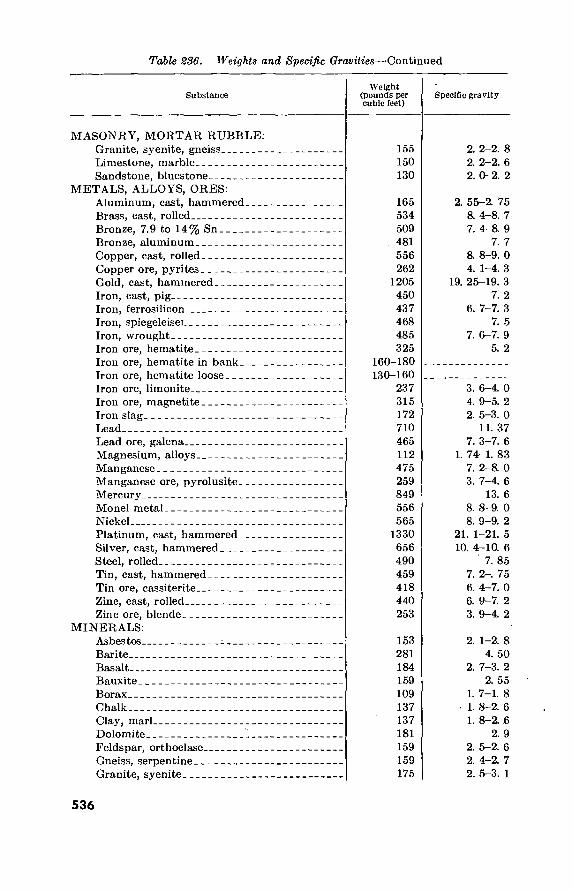
Table 236. Weights and Specific Gravities—-Continued
Substance Weight
(pounds per cubic feet)
Specific gravity
MASONRY, MORTAR RUBBLE: Granite, syenite, gneiss Limestone, marble Sandstone, bluestone
METALS, ALLOYS, ORES: Aluminum, cast, hammered Brass, cast, rolled Bronze, 7.9 to 14% Sn Bronze, aluminum Copper, cast, rolled Copper ore, pyrites Gold, cast, hammered Iron, cast, pig Iron, ferrosilicon Iron, spiegeleiser Iron, wrought Iron ore, hematite Iron ore, hematite in bank. Iron ore, hematite loose Iron ore, limonite Iron ore, magnetite Iron slag Lead Lead ore, galena Magnesium, alloys Manganese Manganese ore, pyrolusite. Mercury Monel metal Nickel Platinum, cast, hammered. Silver, cast, hammered Steel, rolled Tin, cast, hammered Tin ore, cassiterite Zinc, cast, rolled Zinc ore, blende
155 150 130
2. 2-2. 8 2. 2-2. 6 2. 0-2. 2
165 534 509
. 481 556 262
1205 450 437 468 485 325
160-180 130-160
237 315 172 710 465 112 475 259 849 556 565
1330 656 490 459 418 440 253
2. 55-2. 75 8. 4-8. 7 7. 4-8. 9
7. 7 8. 8-9. 0 4. 1-4. 3
19. 25-19. 3 7! 2
6. 7-7. 3 7. 5
7. 6-7. 9 5. 2
3. 6-4. 0 4. 9-5. 2 2. 5-3. 0
11. 37 7. 3-7. 6
1. 74-1. 83 7. 2-8. 0 3. 7-4. 6
13. 6 8. 8-9. 0 8. 9-9. 2
21. 1-21. 5 10. 4-10. 6
7. 85 7. 2-, 75 6. 4-7. 0 6. 9-7. 2 3. 9-4. 2
MINERALS: Asbestos Barite Basalt Bauxite Borax Chalk Clay, marl Dolomite Feldspar, orthoclase Gneiss, serpentine,- Granite, syenite
153 281 184 159 109 137 137 181 159 159 175
2. 1-2. 8 4. 50
2. 7-3. 2 2. 55
1. 7-1. 8 • 1. 8-2. 6
1. 8-2. 6 2. 9
2. 5-2. 6 2. 4-2. 7 2. 5-3. 1
536
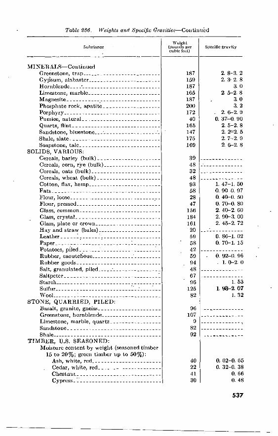
Table 286. Weights and Specific Gravities—Continued
Substance
MINERALS—Continued Greenstone, trap Gypsum, alabaster Hornblende • Limestone, marble Magnesite Phosphate rock, apatite Porphyry Pumice, natural Quartz, flint Sandstone, bluestone ' i Shale, slate Soapstone, talc
SOLIDS, VARIOUS: Cereals, barley (bulk) Cereals, corn, rye (bulk) Cereals, oats (bulk) Cereals, wheat (bulk) Cotton, flax, hemp Fats Flour, loose Flour, pressed Glass, common Glass, crystal Glass, plate or crown . Hay and straw (bales) Leather 7 Paper 1 Potatoes, piled Rubber, caoutchouc Rubber goods Salt, granulated, piled Saltpeter ' Starch Sulfur ; Wool
STONE, QUARRIED, PILED: Basalt, granite, gneiss Greenstone, hornblende Limestone, marble, quartz Sandstone Shale
TIMBER, U.S. SEASONED: Moisture content by weight (seasoned timber
15 to 20%; green timber up to 50%): Ash, white, red Cedar, white, red Chestnut Cypress
Weight (pounds per cubic feet)
Specific gravity
187 159 187 165 187 200 172 40
165 147 175 169
2. 8-3. 2 2. 3-2. 8
3. 0 2. 5-2. 8
3. 0 3. 2
. 2. 6-2. 9 0. 37-0. 90
2. 5-2. 8 2. 2-2. 5 2. 7-2. 9 2. 6-2. 8
39 48 32 48 93 58 28 47
156 184 161 20 59 58 42 59 94 48 67 96
125 82
1. 47-1. 50 0. 90-0. 97 0. 40-0. 50 0. 70-0. 80 2. 40-2. 60 2. 90-3. 00 2. 45-2. 72
0. 86-1. 02 0. 70-1. 15
0. 92-0. 96 . 1. 0-2. 0
1. 53 1. 93-2. 07
1. 32
96 107
9 82 92
40 22 41 30
0. 62-0. 65 0. 32-0. 38
0. 66 0. 48
537

Table 286. Weights and Specific Gravities—Continued
Substance
TIMBER, U.S. SEASONED—Continued Elm, white Fir, Douglas Spruce Fir, eastern Hemlock Hickory Locust Maple, hard Maple, white Oak, chestnut Oak, live Oak, red, black Oak, white Pine, Oregon Pine, red Pine, white Pine, yellow, longleaf Pine, yellow, shortleaf Poplar Redwood, California Spruce, white, black Walnut, black Walnut, white
Weight (pounds per cubic feet)
Specific gravity
45 32 25 29 49 46 43 33 54 59 41 46 32 30 26 44 38 30 26 27 38 26
0. 72 0. 51 0. 40
0. 42-0. 52 0. 74-0. 84
0. 73 0. 68 0. 53 0. 86 0. 95 0. 65 0. 74 0. 51 0. 48 0. 41 0. 70 0. 61 0. 48 0. 42
0. 40-0. 46 0. 61 0. 41
The specific gravities of solids and liquids refer to water at 4° C. and 760 mm. pressure. The weights per cubic foot are derived from average specific gravities, except where stated that weights are for bulk, heaped or loose material, etc.
b. Weights of Certain Building Materials. Table 237. Weights of Building Materials
Material Weight,
pounds per square foot
CEILINGS: Gypsum ceiling block, 2" thick unplastered Plaster, on tile or concrete Plaster, and metal lath Plaster, and wood lath_. Plaster board, unplastered Suspended, metal lath and plaster
FLOORS:
10 5 8 8 3
10
Cement finish, per inch thick Cinder concrete, per inch thick Cinder concrete fill, per inch thick Gypsum slab, per inch thick Hardwood flooring, %" thick Sheathing, white, red, or Oregon pine, spruce, or hemlock,
Yi" thick
12 9 5 5 4
2/2
538

Table 287. Weights of Building Materials—Continued
Material Weight,
pounds per square foot
FLOORS—Continued Sheathing, yellow pine, 1" thick Terrazzo, tile, mastic, linoleum, per inch thick, including base. Wood block, creosoted, 3” thick
PARTITIONS:
4 12 15
Channel studs, metal lath, cement plaster, solid, 2" thick Hollow clay tile, 2” Hollow clay tile, 3” Hollow clay tile, 4" Hollow clay tile, 5" Hollow clay tile, 6” Hollow clay tile, 8" Hollow clay tile, 10" Plaster, }£", on gypsum block or clay tile (one side) Solid gypsum block, 2" Solid gypsum block, 3" Steel partitions Studs, 2" x 4" plaster board, J4" plaster both sides Studs, 2" x 4" wood or metal lath, %" plaster both sides
ROOFS: Corrugated metal Ready roofing, 3 ply Roofing felt, 3 ply and gravel Roofing felt, 5 ply and gravel Roofing felt, 3 ply and slag - Roofing felt, 5 ply and slag Shingles, wood Tile or slate
WALLS:
20 13 16 18 20 25 30 35
4
13 4
18 18
(Par. 180) 1
5>S 6/2
5>$ 5/2
2 5-20
Brick, 9" thick Brick, 13" thick Brick, 18" thick Brick, 22" thick Brick, 26" thick Brick 4", tile backing 4" Brick 4", tile backing 8" Brick 8", tile backing 4" Brick 9", tile backings" Corrugated metal siding Limestone 4", brick 9" Limestone 4", brick 13" Limestone 4", tile 8" Limestone 4", tile 12" Wall tile, 6" thick Wall tile, 8" thick Wall tile, 10" thick Wall tile, 12" thick Windows, glass, frame, and sash
84 121 168 205 243
60 75
100 115
(Par. 180) 140 175
90 100 30 33 40 45
8
539
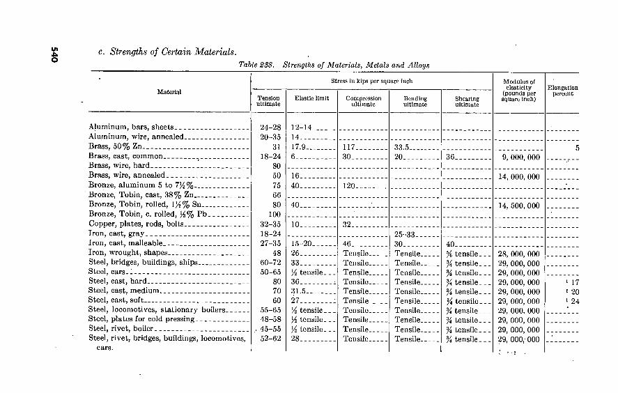
540
c. Strengths of Certain Materials.
Table 288. Strengths of Materials, Metals and Alloys
Material
Aluminum, bars, sheets Aluminum, wire, annealed Brass, 50% Zn Brass, cast, common Brass, wire, hard Brass, wire, annealed Bronze, aluminum 5 to 7%% Bronze, Tobin, cast, 38% Zn Bronze, Tobin, rolled, 1)4% Sn Bronze, Tobin, c. rolled, y3% Pb Copper, plates, rods, bolts Iron, cast, gray Iron, cast, malleable Iron, wrought, shapes Steel, bridges, buildings, ships Steel, cars.. Steel, cast, hard Steel, cast, medium Steel, cast, soft Steel, locomotives, stationary boilers Steel, plates for cold pressing Steel, rivet, boiler Steel, rivet, bridges, buildings, locomotives,
Stress in kips per square inch
Tension ultimate
24-28 20-35
31 18-24
80 50 75 66 80
100 32-35 18-24 27-35
48 60-72 50-65
80 70 60
55-65 48-58 45-55 52-62
Elastic limit
12-14. 14 17.9... 6
16. 40.
40.
10.
15-20 26 33 'A tensile. 36 31.5 27 A tensile . A tensile. Ai tensile. 28
Compression ultimate
117. 30. .
120.
32.
46 Tensile- Tensile. Tensile. Tensile. Tensile. Tensile. Tensile. Tensile. Tensile. Tensile.
Bending ultimate
33.5. 20...
25-33.. 30 Tensile. Tensile. Tensile- Tensile. Tensile. Tensile. Tensile. Tensile. Tensile. Tensile.
Shcarlng ultimate
36.
40 % tensile. % tensile. % tensile. A tensile. % tensile . At tensile. % tensile. % tensile . A4 tensile. A4 tensile .
Modulus of elasticity
(pounds per square Inch)
Elongation percent
9, 000, 000
14, 000, 000
14, 500, 000
28, 000, 000 29, 000, 000 29, 000, 000 29, 000, 000 29, 000, 000 29, 000, 000 29, 000, 000 29, 000, 000 29, 000, 000 29, 000,- 000
1 17 1 20 1 24
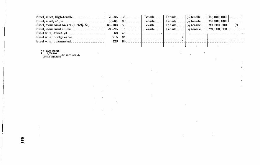
Steel, rivet, high-tensile Steel, rivet, ships Steel, structural nickel (3.25% Ni) Steel, structural silicon Steel wire, annealed •. Steel wire, bridge cable Steel wire, unannealed
12" gage length. 1 1,500,000
tensile strength , 8" gage length.
70-85 55-65
85-100 80-95
80 215 120
38- 30- 50. 45. 40. 95. 60.
Tensile. Tensile. Tensile.
■ Tensile.
Tensile. Tensile. Tensile. Tensile.
Yi tensile. Y* tensile. Y* tensile . Yi tensile.
29, 000, 000 29, 000, 000 29, 000, 000 29, 000, 000
(2)

Table 838. Strengths of Materials, Building Materials
Material Average ultimate stress (pounds per square inch)
Compression Tension Bending
Safe working stress (pounds per square Inch)
Compression Bearing Shearing
Modulus of elasticity (pounds per square Inch)
Masonry, brick, common Masonry, granite Masonry, limestone, bluestone- Masonry, sandstone Masonry, rubble Ropes, cast steel hoisting Ropes, manila Ropes, standing, derrick Stone, bluestone Stone, granite, gneiss Stone, limestone, marble Stone, sandstone Stone, slate..
10, 000 200
12, 000 12, 000 8, 000 5, 000
10, 000
80, 000 8, 000
70, 000 1, 200 1, 200
800 150
" 3, 000
600
2, 500 1, 600 1, 500 1, 200 5, 000
420 350 280 140
600 500 400 250
1, 200 1, 200
800 500
1, 000
1, 200 1, 200
800 500
1, 000
200 200 150 150 175
7, 000, 000 7, 000, 000 7, 000, 000 3, 000, 000
14, 000, 000

d. Coefficients of Expansion of Certain Materials. The coefficient of linear expansion (e) of a material is the change in length, per unit of length, for a change of one degree of temperature. The coefficient of surface expansion is approximately two times the linear coefficient, and the coefficient of volume expansion, for solids, is approximately three times the linear coefficient.
(1) A bar, free to move, will increase in length with an increase in temperature and will decrease in length with a decrease in temperature. The change in length will be dl, where ^ is the coefficient of linear expansion, t the change in tempera- ture, and l the length. If the ends of a bar are fixed, a change in temperature (t) will cause a change in the unit stress of Eet, and in the total stress of AEet, where A is the cross sectional area of the bar and E the modulus of elasticity.
(2) Table 239 gives the coefficient of linear expansion for 100°, of 100 times the value indicated above. Example: A piece of medium steel is exactly 40 feet long at 60° F. Find the length at 90° F. assuming the ends free to move.
Change of length = €11=^^^^=.00804 foot.
(3) The length at 90° F. is 40.00804 feet. Example: A piece of medium steel is exactly 40 feet long and the ends are fixed. If the temperature increases 30° F., what is the resulting change in the unit stress?
t i 29,000,000X0.00067X30 Change in unit stress = Eet=
= 5830 lbs. per sq. in.
543

544
Table 289. Coefficients of Expansion of Materials for 100 Degrees—lOOC
Materials
METALS AND ALLOYS: Aluminum, wrought Brass Bronze Copper Iron, cast, gray Iron, wrought Iron, wire Lead Magnesium, various alloys . Nickel Steel, cast ..... Steel, hard Steel, medium Steel, soft
TIMBER
Fir Maple. Oak Pine...
parallel to fiber.
Linear expansion
Centigrade
0. 00231 . 00188 . 00181 . 00168 . 00106 . 00120 . 00124 . 00286 . 0029 . 00126 . 00110 . 00132 . 00120 . 00110
0. 00037 .00064 . 00049 . 00054
Fahrenheit
0. 00128 . ($104 . Ö0101 . 00093 . 00059 . QÓ067 . bÓ069 .00159 . Q016 . 00070 . 00061 . 0ÖÖ73 . 00067 . 00061
0. 00021 . 0$,036 . 0(6027 . 00030
Materials
METALS AND ALLOYS—Continued Steel, stainless, 18-8 : Zinc, rolled
STONE AND MASONRY: Ashlar masonry Brick masonry Cement, portland Concrete Granite Limestone Marble Plaster. Rubble masonry J Sandstone Slate
TIMBER
Fir.... Maple. Oak Pine...
> perpendicular to fiber..
Linear expansion
Centigrade Fahrenheit
,00178 , 00311
,00063 ,00055 . 00107 ,00143 ,00084 .00080 , 00100 ,00166 , 00063 ,00110 .00104
0. 0058 . 0048 . 0054 . 0034
.00099
. 00173
, 00035 . 00031 . 00059 .00079 . 00047 . 00044 . 00056 . 00092 .00035 . 00061 . 00058
0. 0032 . 0027; .0030 . 0019

545
1 c.
O--
4__ 10_
Volume
1. 000126 1. 000000 1. 000257
20 _
30_ 40-
EXPANSION OF WATER
Maximum Density = 1
Volume
l. 001732 1. 004234 1. 007627
50. 60_ 70_
' C. Volume
1. 011877 1. 010954 1. 022384
’ c.
80- _ 90- _ 100-
Volume
1. 029003 1. 035829 1. 043116

220. Density of Gases Table 240. Density of Gases
Weight
Gas Grams per liter Pounds per cubic
foot
Specific gravity
Air=0 0=1
Air Acetylene Ammonia. Argon Bromine Butane Carbon dioxide Carbon monoxide Chlorine Cial gas Cyanogen Ethane. Ethylene Fluorine Helium Hydrobromic acid Hydrochloric acid Hydrofluoric acid Hydrogen Hydrogen sulfide Krypton Methane Methyl chloride Methyl ether Neon Nitrogen Nitric oxide Nitrous oxide Oxygen... Propane Steam at 100° C Sulphur dioxide Xenon
2930 1791 7708 7809 14 594 9768 2504 221 41-0. 96 323 3562 2609 70 1785 616 6398 922 08987 538 708 7168 304 110 9002 2507 3402 9777 42905 0196 598 9266 851
0. 00872 0. 07361 0. 04812 0. 11118 0. 446 0. 1619 0. 12341 0. 07806 0. 2011 0. 026-0. 060 0. 1450 0. 08467 0. 07872 0. 106 0. 01115 0. 2257 0. 10237 0. 0576 0. 00561 0. 09602 0. 2315 0. 04475 0. 1438 0. 1317 0. 05620 0. 07808 0. 08367 0. 12347 0. 08921 0. 12608 0. 0373 0. 18270 0. 3653
1. 0000 0. 9119 0. 5961 1. 3773 5. 52 2. 006 1. 5289 0. 9671 2. 491 0. 32-0. 74 1. 797 1. 0489 0. 9752 1. 31 0. 1381 2. 797 1. 2682 0. 713 0. 06950 1. 189 2. 868 0. 5544 1. 782 1. 632 0. 6962 0. 9673 1. 0365 1. 5296 1. 1052 1. 5620 0. 462 2. 2634 4. 525
0. 9048 0. 8251 0. 5394 1. 2462 5. 00 1. 815 1. 3833 0. 8750 2. 254 0. 29-0. 67 1. 626 0. 9490 0. 8823 1. 19 0. 1249 2. 530 1. 1475 0. 645 0. 06289 1. 076 2. 595 0. 5016 1. 612 1. 477 0. 6299 0. 8752 0. 9378 1. 3839 1. 0000 1. 4132 0. 418 2. 0479 4. 094
Notes. The gases in this table, or the elements of which they are composed, are the isotopes or mixtures of isotopes normally occurring in nature.
221. Contents of Horizontal Tanks The cubic content of a horizontal cylindrical tank of circular or
elliptical cross section is given by the formula—
' H(Si)^0.003Wi
whore C is the capacity in gallons and d and / are, respectively, the diameter and the length in inches. For a tank partially filled with
546

liquid, the volume of liquid as a percentage of the total capacity is related to the depth of liquid as a percentage of the total depth (diameter) as shown in table 241. Use columns 1 and la if the per- centage depth is 50 percent or less; columns 2 and 2a if greater than 50 percent.
Table S41. Capacities of Partially Filled Tanks
Percent of depth Percent of capacity Percent of depth Percent öf capacity
1—filled 2—unfilled
1 2 3 4 5 6 7 8 9
10 11 12 13 14 15 16 17 18 19 20 21 22 23 24 25
la—filled 2a—unfilled
99 98 97 96 95 94 93 92 91 90 89 88 87 86 85 84 83 82 81 80 79 78 77 76 75
0. 20 0. 50 0. 90 1. 34 1. 87 2. 45 3. 07 3. 74 4. 45 5. 20 5. 98 6. 80 7. 64 8. 50 9. 40
10. ,32 11. 27 12. 24 13. '23 14. '23 15..26 16. 32 17. 40 18. 50 19. 61
1—filled 2—unfilled
99. 80 99. 50 99. 10 98. 66 98. 13 97. 55 96. 93 96. 26 95. 55 94.-80 94. 02 93. 20 92. 36 91. 50 90. 60 89. 68 88. 73 87. 76 86. 77 85.77 84. 74 83. 68 82. 60 81. 50 80. 39
26 27 28 29 30 31 32 33 34 35 36 37 38 39 40 41 42 43 44 45 46 47 48 49 50
la—filled 2a—unfilled
74 73 72 71 70 69 68 67 66 65 64 63 62 61 60 59 58 57 56 55 54 53 52 51 50
20. 73 21. 86 23. 00 24. 07 25. 31 26. 48 27. 66 28. 84 30. 03 31. 19 32. 44 33. 66 34. 90 36. 14 37. 39 38. 64 39. 89 41. 14 42. 40 43. 66 44. 92 46. 19 47. 45 48. 73 50. 00
79. 27 78. 14 77. 00 75. 93 74. 69 73. 52 72. 34 71. 16 69. 97 68. 81 67. 56 66. 34 65. 10 63. 86 62. 61 61. 36 60. 11 58. 86 57. 60 56. 34 55. 08 53. 81 52. 55 51. 27 50. 00
222. Volume oí Piled.Sand or Gravel To obtain the capacity of a conical pile, enter figure 110 on the
horizontal line at the bottom with the height of the pile in feet. Proceed upward to the point where the proper curve intersects this vertical line. Proceed horizontally from this intersection to the column at the left and read capacity in tons. For example, a 24-foot- high conical pile of gravel will hold 1,770 tons. (See arrow and dotted line on chart.) For a pile shaped as shown, add to the capacity of one conical pile the capacity of an A-shaped pile from the “scale in tons per linear foot of storage.” For example (see arrow and dotted line) an A-shaped pile of sand 22 feet high holds 28.8 tons per linear foot.
547 533506”—60 36

8 10 .12 14 16 18 20 22 24 26 28 30 32 32QQ
I M II II II II II I II II CAPACITIES PER LIN.FT. OF A-SHAPED PILE
3100
3000
2900
2800
2700 WIDTH OF PILE _ BASE 2600
2500
40 2400
I 45 2300
2200
è Z1QQ
<r_J£L 2000 ^ _S5_
1900
1600 70 1770 1700
Í 40 80 1600
£ 85 1500
90 45 1400
25 1300
100 50 1200
100 05
1000 o 110
900 5
120 60 800
700 125
130 600
135 500
70 140 400
300 145 CAPACITY PER CONE
U SHAPED PILE 4— 150 75 200
100 155
160 80
0 2 4 LCHOTH or CROSS KCTICM
8 10 12 14 16 18 20 22 24 26 28
HEIGHT OF PILE IN FEET H
Figure 110. Volume of piled sand or gravel.
223. Safe Loads on Wood Piles Safe loads may be limited by maximum values considered allowable,
by skin friction, or by column action. The values obtained are ap- proximations only.
548

a. Maximum Allowable Loads. All pile formulas being empirical, maximum loads per pile for semipermanent structures are normally limited to the following:
Pile diameter, inchese 8 10 12 14 16 Maximum allowable load, tons 16 24 30 36 42 ^
b. Skin Friction. This value for safe load, which may govern for piles in soft formations, is obtained from data or test loads as follows:
(1) Driving data. (a) Piles driven by drophammer:
„ 2'Wh s+1.0
(b) Piles driven by single-acting steam hammer:
P= ^ (i= stroke of ram in feet) s+0.1
(c) Piles driven by double-acting steam hammer:
2E s+0.1
Where P=safe load in pounds per pile W=weight of drophammer or ram /¡,=fall of drophammer in feet or stroke of ram in inches •s = average penetration in inches per blow for the last 6 blows
of drophammer or 20 blows of steam hammer P= driving energy in foot-pounds per blow of double-acting
hammer, estimated as follows:
Weight of hammer {-pounds) Energy in foot-
Strokes per minute pounds per blow
5,000.
7,000.
225 195 170 145 140 135 130
4, 150 3, 720 3, 280 8, 750 8, 100 7, 500 6, 800
(2) Test loads. Normally test loads are increased 5 tons at 48-hour intervals. The maximum safe load per pile is one-half the load which in 48 hours produces settlement of inch, not counting any settlement produced during and immediately after applying the increment.
c. Column Action. Piles with considerable unsupported length or with eccentric or lateral loads may require design as columns partially
« Measured at a point one-third the length of the pile from the butt, b Obtainable only with the heaviest military driving equipment.
549

fixed at one end, using formulas given in chapter 9. The fixation must be estimated. It may be high or, as for piles bearing on rock with light overburden, very low.
224. Conversion Factors Table 2^2. Conversion Factors
Acres acres acres acres acres acre-feet ares ares atmospheres atmospheres atmospheres atmospheres atmospheres atmospheres
Multiply by to obtain
43.560 4,047
1.562X IO“3
5645.38 4,840
43.560 0.02471
100 76.0
.29.92 33.90 10,333 14.70 1.058
square feet, square meters, square miles, square varas, square yards, cubic-feet, acres. square meters, cms. of mercury, inches of mercury, feet of water, kgs. per square meter, pounds per sq. inch, tons per sq. foot.
Bars bars bars bars bars board-feet British thermal units British thermal units British thermal units British thermal units British thermal units British thermal units B.t.u. per min B.t.u. per min B.t.u. per min B.t.u. per min B.t.u. per sq. ft. per min bushels bushels bushels bushels bushels bushels
9.870 X10⁻⁷
1 0.01020
2.089X10⁻³ 1.450 X IO“5
144 sq. in.X 1 in. 0.2520 777:5
3.927 X10-< 1.054 107.5
2.928 X 10⁻⁴
12.96 0.02356 0.01757
17.57 0.1220 1.244 2,150
0.03524 ■ 4
64 32
atmospheres, dynes per sq. cm. kgs. per square meter pounds per sq. foot, pounds per sq. inch, cubic inches, kilogram-calories, foot-pounds, horse-power-hours, joules. kilogram-meters. kilowatt-hours. foot-pounds per sec. horse-power. kilowatts. watts. watts per square inch. cubic feet. cubic inches. cubic meters. pecks. pints (dry). quarts (dry).
Centares centigrams. centiliters.. centimeters centimeters centimeters
1 0101 0.01
0.3937 0.01 393.7
square meters. grams. liters. inches. meters. mils.
550

Table 21ß. Conversion Factors—Continued
Multiply by to obtain
centimeters centimeters-dynes centimeter-dynes centimeter-dynes centimeter-grams cen timeter-grams centimeter-grams centimeters of mercury-. centimeters of mercury. _ centimeters of mercury.. centimeters of mercury.. centimeters of mercury.. centimeters per second _. centimeters per second. . centimeters per second.. centimeters per second. . centimeters per second. . centimeters per second. . cms. per sec. per sec cms. per sec. per sec cms. per sec. per sec .• circular mils circular mils circular mils cord-feet . cords cubic centimeters cubic centimeters cubic centimeters cubic centimeters cubic centimeters cubic centimeters cubic centimeters cubic centimeters cubic feet cubic feet cubic feet cubic feet cubic feet cubic feet cubic feet cubic feet cubic feet per minute cubic feet per minute cubic feet per minute cubic feet per minute cubic inches cubic inches 1 cubic inches cubic inches cubic inches
10 1.020 X10'3
1.020 X IO“8
7.376X10⁻⁸ 980.7 IO“5
7.233X10⁻⁵
0.01316 0.4461 136.0 27.85 0.1934. 1.969
0.03281 0.036
0.6 0.02237
3.728X 10⁻⁴
0.03281 0.036
0.02237 5.067X10⁻⁸ 7.854X10⁻⁷
0.7854 4 ft. X 4 ft.X 1 ft. 8ft.X4ft.X4ft.
3.531X10⁻⁸ 6.102X10⁻²
IO-* 1.308X10-« 2.642 XIO“4
IO“3
2.113X10⁻⁸ 1.057X10⁻⁸ 2.832X10*
1,728 0.02832 0.03704
7.481 28.32 59.84 29.92 472.0 0.1247 0.4720
62.4 16.39
5.787X10-* 1.639X10⁻⁸ 2.143X10⁻⁸ 4.329X10⁻⁸
millimeters. centimeter-grams. meter-kilograms. pound-feet. centimeter-dynes. meter-kilograms. pound-feet. atmospheres. feet of water. kgs. per square meter. pounds per sq. foot. pounds per sq. inch. feet per minute. feet per second. kilometers per hour. meters per minute. miles per hour. miles per minute. feet per sec. per sec. kms. per hour per sec. miles per hour per sec. square centimeters. square inches. square mils. cubic feet. cubic feet. cubic feet. cubic inches. cubic meters. cubic yards. gallons. liters. pints (liq.) quarts (liq.) cubic cms. cubic inches. cubic meters. cubic yards. gallons. liters. pints (liq.). quarts (liq.). cubic cms. per sec. gallons per sec. liters per second, lbs. of water per min. cubic centimeters, cubic feet, cubic meters, cubic yards, gallons.
551

Table 242. Conversion Factors—Continued
cubic cubic cubic cubic
inches inches inches
Multiply by
1.639X10⁻²
0.03463 0.01732
meters 10«
cubic meters cubic meters cubic meters cubic meters cubic meters : cubic meters cubic meters cubic yards cubic yards cubic yards cubic yards cubic yards cubic yards cubic yards cubic yards cubic yards per minute cubic yards per minute cubic yards per minute.
35.31 61,023 1.308 264.2
10J
2113 1057
7.646 X10⁵
27 46,656 0.7646 202.0 764.6 1616 807.9 0.45
3.367 12.74
Days days days decigrams deciliters decimeters degrees (angle) degrees (angle) degrees (angle) degrees per second, _ degrees per second-, degrees per second-- dekagrams dekaliters dekameters drams drams dynes dynes dynes dynes per square cm
. 24 1440
86,400 0.1 0.1 0.1 60
0.01745 3600
0.01745 0.1667
0.002778 10 10 10
1.772 0.0625
1.020X10⁻³
7.233X10⁻⁵
2.248X10⁻⁸ 1
Ergs ergs. ergs- ergs_ ergs_ ergs_
9.486X10-» 1
7.376X10⁻⁸ 1.020X10⁻⁸
io-7
2.390X10⁻¹¹
to obtain
liters. pints (liq.). quarts (liq.). cubic centimeters, cubic feet, cubic inches, cubic yards, gallons, liters. pints (liq.). quarts (liq.). cubic centimeters, cubic feet, cubic inches, cubic meters, gallons, liters. pints (liq.). quarts (liq.). cubic feet per second, gallons per second, liters per second.
hours. minutes. seconds. grams. liters. meters. minutes. radians. seconds. radians per second. revolutions per min. revolutions per sec. grams. liters. meters. grams. ounces. grams. poundals. pounds. bars.
British thermal units. dyne-centimeters. foot-pounds. gram-centimeters. joules. kilogram-calories.
552

Table Conversion Factors—Continued
Multiply by to obtain
ergs ergs per second- ergs per second- ergs per second- ergs per second- ergs per second- ergs per second-
Fathoms feet feet feet feet foot feet of water feet of water feet of water feet of water feet of water feet per minute feet per minute feet per minute feet per minute feet per minute feet per second feet per second feet per second feet per second feet per second feet per second feet per 100 feet feet per sec. per sec feet per sec. per sec feet per sec. per sec feet per sec. per sec foot-pounds foot-pounds foot-pounds foot-pounds foot-pounds foot-pounds foot-pounds foot-pounds per minute- foot-pounds per minute- foot-pounds per minute- foot-pounds per minute- foot-pounds per minute, foot-pounds per second- foot-pounds per second- foot-pounds per second- foot-pounds per second.
1.020X10⁻⁸
5.692X10-" 4.426 X 10⁻⁶
7.376X10-* 1.341X10-‘o 1.434X10-»
lO-io
6 30.48
12 0.3048
.36
'Á 0.02950 0.8826 304.8 62.43
0.4335 0.5080 0.01667 0.01829 0.3048 0.Ó1136
30.48 1.097
0.5921 18.29
0.6818 0.01136
1 30.48 1.097
0.3048 0.6818
1.286X10⁻³
1.356X 10⁷
5.050X10⁻⁷
1.356 3.241 X 10~4
0.1383 3.766X10⁻⁷
1.286X10⁻³
0.01667 3.030X10⁻⁵
3.241 XIO“4
2.260X10⁻⁸ 7.717X10⁻² 1.818X10⁻⁸ 1.945X10⁻² 1.356X10⁻³
kilogram-meters. B.t. units per minute, foot-pounds per minute, foot-pounds per second, horse-power, kg.-calories per minute, kilowatts.
feet. centimeters. inches. meters. varas. yards. atmospheres, inches of mercury, kgs. per square meter, pounds per sq. ft. pounds per sq. inch, centimeters per sec. feet per second, kilometers per hour, meters per minute, miles per hour, centimeters per sec. kilometers per hour, knots per hour, meters per minute, miles per hour, miles per minute, per cent grade, cms. per sec. per sec. kms. per hr. per sec. meters per sec. per sec. miles per hr. per sec. British thermal units, ergs. horse-power-hours. joules. kilogram-calories. kilogram-meters. kilowatt-hours. B.t. units per minute, foot-pounds per sec. horse-power, kg.-calories per min. kilowatts. B.t. units per minute, horse-power, kg.-calories per min. kilowatts.
553

Table 242. Conversion Factors—Continued
furlongs
Multiply by
40 rods.
to obtain
Gallons gallons gallons gallons gallons - gallons gallons gallons gallons per minute gallons per minute gills gills grains (troy) grains (troy) grains (troy) grams grams grams grams grams grams grams grams gram-calories gram-centimeters _. gram-centimeters.. gram-centimeters.. gram-centimeters.. gram-centimeters. . gram-centimeters. . grams per cm grams per cu. cm., grams per cu. cm__ grams per cu. cm..
3785 0.1337
231 3.785X10⁻³
4.951X10⁻³ 3.785
8 4
2.228X IO“3
0.06308 0.1183 0.25
1
0.06480 0.04167
980.7 15.43 IO-3
103
0.03527 0.03215 0.07093
2.205X10⁻³ 3.968X10⁻³ 9.302X IO“3
980.7 7.233X10⁻³ 9.807X10-« 2.344X10⁻³
10-5
5.600X10⁻³ 62.43
0.03613 3.405X 10⁻⁷
cubic centimeters, cubic feet, cubic inches, cubic meters, cubic yards, liters. pints (liq.). quarts (liq.). cubic feet per second, liters per second, liters. pints (liq.). grains (av.). grams. pennyweights (troy), dynes. grains (troy). kilograms. milligrams. ounces. ounces (troy). poundals. pounds. British thermal units. British thermal units, ergs. foot-pounds. joules. kilogram-calories, kilogram-meters, pounds per inch, pounds per cubic foot, pounds per cubic inch, pounds per mil-foot.
Hectares hectares hectograms hectoliters hectometers hectowatts hemispheres (sol. angle) hemispheres (sol. angle) hemispheres (sol. angle) horse-power horse-power horse-power horse-powen horse-power
2.471 1.076X Id5
100 100 100 100 0.5 4
6.283 42.44 33,000 -
550 1.014 10.70
acres. square feet. grams. liters. meters. watts. sphere. spherical right angles, steradians. B.t. units per min. foot-pounds per min. foot-pounds per sec. horse-power (metric), kg.-calories per min.
554

Table 342. Conversion Factors—Continued
Multiply by to obtain
horse-power horse-power horse-power (boiler), horse-power (boiler) . horse-power-hours - _ horse-power-hours -. horse-power-hours.. horse-power-hours- . horse-power-hours.. horse-power-hours-. hours hours
Inches inches inches inches of inches of inches of inches of inches of inches of inches of inches of inches of inches of inches of
Joules. joules. joules. joules. joules. joules.
mercury. mercury. mercury. mercury. mercury. water water water water water water
Kilograms kilograms kilograms kilograms kilograms kilogram-calories kilogram-calories kilogram-calories kilogram-calories kilogram-calories kilogram-calories kg.-calories per min. kg.-calories per min. kg.-calories per min. kgs.-cms. squared kgs.-cms. squared
0.7457 745.7
33,520 9.804 2547
1.98X10» 2.684X10»
641.7 2.737X10»
0.7457 60
3600
2.540 103
.03 0.03342
1.133 345.3 70.73
0.4912 0.002458 0.07355
25.40 0.5781 5.204
0.03613
9.486 X 10⁻⁴
107
0.7376 2.390X10⁻⁴
0.1020 2.778X 10~*
980,665 103
70.93 2.2046
1.102X10⁻³
3.968 3088
1.588X 10⁻³
4183 426.6
1.162X 10⁻³
51.43 0.09351 0.06972
2.373X 10⁻³
0.3417
kilowatts. watts. B.t.u. per hour, kilowatts. British thermal units. foot-pounds. joules. kilogram-calories. kilogram-meters. kilowatt-hours. minutes. seconds.
centimeters.. mils. varas. atmospheres, feet of water, kgs. per square meter, pounds per square ft. pounds per square in. atmospheres, inches of mercury, kgs. per square meter, ounces per square in. pounds per square ft. pounds per square in.
British thermal units, ergs. foot-pounds. kilogram-calories. kilogram-meters. watt-hours.
dynes, grams, poundals. pounds, tons (short). British thermal units, foot-pounds, horse-power-hours, joules. kilogram-meters, kilowatt-hours, foot-pounds per sec. horse-power, kilowatts. pounds-feet squared, pounds-inches squared.
555

Table 242. Conversion Factors—:Continued
Multiply by to obtain
kilogram-meters kilogram-meters kilogram-meters. 1 kilogram-meters kilogram-meters kilogram-meters kgs. per cubic meter. _ kgs. per cubic meter. . kgs. per cubic meter. . kgs. per cubic meter.. kgs. per meter kgs. per square meter. kgs. per square meter. kgs. per square meter, kgs. per square meter, kgs. per square meter. •kgs. per square meter, kgs. per sq. millimeter. kilolines kiloliters kilometers i kilometers kilometers kilometers kilometers kilometers per hour kilometers per hour kilometers per hour kilometers per hour kilometers per hour kilometers per hour kms. per hour per sec., kms. per hour per sec.. kms. per hour per sec.. kms. per hour per sec. : kilometers per min kilowatts kilowatts kilowatts kilowatts kilowatts kilowatts kilowatt-hours kilowatt-hours kilowatt-hours kilowatt-hours kilowatt-hours kilowatt-hours knots knots knots
9.302X IO“3
9.807 X10⁷
7.233 9.807
2.344X10⁻³ 2.724 X 10-»
IO“3
0.06243 3.613X10-« 3.405 X lO-10
0.6720 9.678X10⁻³
98.07 3.281X10⁻³ 2.896X lO-3
0.2048 1.422X10⁻³
106
103
103
105
3281 103
0.6214 1093.6 27.78 54.68
0.9113 0.5396 16.67
0.6214 27.78
0.9113 0.2778 0.6214
60 56.92
4.425 X 10⁴
737.6 1.341 14.34
103
3415 2.655X10³
1.341 3.6X10»
860.5 3.671X10⁵
51.48 1.689 1.853
British thermal units, ergs. foot-pounds. joules. kilogram-calories, kilowatt-hours, grams per cubic cm. pounds per cubic foot, pounds per cubic inch, pounds per mil. foot, pounds per foot, atmospheres, bars. feet of water, inches of mercury, pounds per square ft. pounds per square in. kgs. per square meter, maxwells, liters. centimeters. feet. meters. miles. yards. centimeters per sec. feet per minute, feet per second, knots per hour, meters per minute, miles per hour, cms. per sec. per sec. ft. per sec. per sec. meters per sec. per sec. miles per hr. per sec. kilometers per hour. B.t. units per min. foot-pounds per min. foot-pounds per sec. horse-power, kg.-calories per min. watts. British thermal units, foot-pounds, horse-power-hours, joules. kilogram-calories, kilogram-meters. centimeters per sec. feet per second, kilometers per hour.
556

TaWe S42. Conversion Factors—Continued
Multiply by to obtain
knots.
Links (engineer’s) . links (surveyor’s). liters liters liters liters liters liters liters liters liters per minute., liters per minute.. logioiV log e N or ln N lumens per sq. ft.
Meters meters meters meters meters meters meter-kilograms meter-kilograms meter-kilograms meters per minute meters per minute meters per minute meters per minute meters per minute meters per second meters per second meters per second meters per second meters per second meters per second meters per sec. per sec. meters per sec. per sec. meters per sec. per sec. microns miles miles miles miles miles.. miles per hour miles per hour miles per hour miles per hour
1.152
12 7.92 103
0.03531 61.02 io-3
1.308X10⁻³
0.2642 2.113 1.057
5.885 X 10⁻⁴
4.403 X 10⁻³
2.303 0.4343
1
100 3.2808 39.37 io-3
103
1.0936 9.807X 10⁷
I05
7.233 1.667 3.281
0.05468 0.06
0.03728 196.8 3.281
3.6 0.06 2.237 ,
0.03728 3.281
3.6 2.237 IO“«
1.609X100 5280
1.6093 1760
1900.8 44.70
88 1.467 1.6093
miles per hour.
inches. inches. cubic centimeters. cubic feet. cubic inches. cubic meters. cubic yards. gallons. pints (liej.). quarts (liq.). cubic feet per second. gallons per second. log € N or ln N. logiofV. foot-candles.
centimeters. feet. inches. kilometers. millimeters. yards. centimeter-dynes, centimeter-grams, pou nd-fect. centimeters per sec. feet per minute, feet per second, kilometers per hour, miles per hour, feet per minute, feet per second, kilometers per hour, kilometers per min. miles per hour, miles per minute, feet per sec. per sec. kms. per hour per sec. miles per hour per sec. meters, centimeters, feet. kilometers. yards. varas. centimeters per sec. feet per minute, feet per second.
557

Table 242: Conversion Factors—Continued
Multiply
miles per hour miles per hour.-. miles per hour per sec..- miles per hour per sec miles per hour per sec miles per hour per sec miles per minute miles per minute-- miles per minute miles per minute miles per minute milliers milligrams milliliters millimeters millimeters millimeters mils mils 1 miner’s inches minutes (angle) minutes (angle) months •_ months months ! months myriagrams myriameters myriawatts
by to obtain
0.8684 26.82
■ 44.70 1.467
1.6093 0.4470 2682 88
1.6093 0.8684
60 103
lO“3
IO“3
0.1 0.03937
39.37 0.002540
lO“3
1.5 2.909 X10⁻¹
60 30.42 730
43,800 2.628X10»
10 10 10
knots per hour, meters per minute, cms. per sec. per sec. feet per sec. per sec. kms. per hour per sec. M. per sec. per sec. centimeters per sec. feet per second, kilometers per min. knots per minute, miles per hour, kilograms, grams, liters. centimeters. inches. mils. centimeters. inches. cubic feet per min. radians. seconds (angle). days. hours. minutes. seconds. kilograms. kilometers. kilowatts.
Nautical miles nautical miles. nautical miles. nautical miles.
6080 1.853 1.152 2027
feet. kilometers. miles. yards.
Ounces ounces ounces ounces ounces (fluid) ounces (fluid) ounces (troy) ounces (troy) ounces (troy) ounces (troy) ounces per square inch
8 437.5 28.35
0.0625 1.805
0.02957 480
31.10 20
0.08333 0.0625
drams. grains. grams. pounds. cubic inches. liters. grains (troy), grams. pennyweights (troy), pounds (troy), pounds per sq. inch.
Pennyweights (troy) pennyweights (troy), pennyweights (troy), perches (masonry)--.
24 1.555 0.05
24.75
grains (troy), grams. ounces (troy), cubic feet.
558

Table .248• Conversion Factors—Continued
Multiply by to obtain
pints (dry) pints (liq.) poundals poundals poundals pounds pounds pounds pounds pounds pounds (troy) pound-feet pound-feet pound-feet pound-feet squared pounds-feet squared pounds-inches squared..- pounds-inches squared pounds of water pounds of water pounds of water pounds of water per min. pounds per cubic foot pounds per cubic foot pounds per cubic foot pounds per cubic foot pounds per cubic inch pounds per cubic inch pounds per cubic inch pounds per cubic inch pounds per foot pounds per inch pounds per mil foot pounds per square foot.. pounds per square foot... pounds per square foot... pounds per square inch., pounds per square inch., pounds per square inch., pounds per square inch., pounds per square inch..
Quadrants (angle). quadrants (angle), quadrants (angle) . quarts (dry) quarts (liq.) quintals quires
Radians. radians..
33.60 28.87 13,826 14.10
0.03108 444,823
7000 453.6
16 32.17
0.8229 1.356 X10⁷
13,825 0.1383 421.3 144
2.926 6.945X 10⁻³
0.01602 27.68
0.1198 2.669 XIO-4
0.01602 16.02
5.787 XIO"1
5.456X10-» 27.68
2.768X 10⁴
1728 9.425 XIO“6
1.488 178.6
2.306X10⁶
0.01602 4.882
6.944 XIO"3
0.06804 2.307 2.036 703.1
14'4
90 5400 1.571 67.20 57.75
100 25
57.30 3438
cubic inches. cubic inches. dynes. grams. pounds. dynes. grains. grams. ounces. poundals. pounds (av.). centimeter-dynes. centimeter-grams. me ter-ki lograms. kgs.-cms. squared. pounds-ins. squared. kgs.-cms. squared. pounds-feet squared. cubic feet. cubic inches. gallons. cubic feet per sec. grams per cubic cm. kgs. per cubic meter, pounds per cubic inch, pounds per mil foot, pounds per cubic cm. kgs. per cubic meter, pounds per cubic foot, pounds per mil foot, kgs. per meter, grams per cm. grams per cubic cm. feet of water, kgs. per square meter, pounds per.sq. inch, atmospheres, feet of water, inches of mercury, kgs. per square meter, pounds per sq. foot.
degrees. minutes. radians. cubic inches. cubic inches. pounds. sheets.
degrees. minutes.
559

Table 21)2. Conversion Factors—Continued
Multiply by to obtain
radians radians per second radians per second radians per second, L
radians per sec. per sec. radians per sec. per sec. radians per sec. per sec. reams revolutions revolutions revolutions.. revolutions per minute- revolutions per minute- revolutions per minute- revs. per min. per min., revs, per min. per min., revs, per min. per min., revolutions per second.. revolutions per second., revolutions per second. _ revs, per sec. per sec revs, per sec. per sec revs, per sec. per sec rods
Seconds {angle) spheres (solid angle)., spherical right angles. spherical right angles. spherical right angles. square centimeters square centimeters square centimeters square centimeters square centimeters square feet square feet square feet square feet square feet square feet square feet sq. feet-feet sqd square inches square inches square inches square inches square inches sq. inches-inches sqd_. sq. inches-inches sqd.. square kilometers
0.637 57.30
0.1592 9.549 573.0 9.549 0.1592
500 360
4 6.283
6 0.1047
0.01667 1.745X 10“3
0.01667 2.778 X lO“4
- 360 6.283
60 6.283 3600
60 16.5
4.848 X10-« 12.57 0.25
0.125 1.571
1.973 X10⁵
1.076X 10⁻³
0.1550 10-«
100 2.296 X 10⁻⁵
929.0 144
0.09290 3.587X10⁻⁸
.1296 1/9
2.074 X10⁴
1.273 X 10» 6.452
6.944 X 10“3
109
645.2 41.62
4.823 X 10⁻⁵
247.1
quadrants. degrees per second. revolutions per sec. revolutions per min. revs, per min. per min. revs, per min. per sec. revs, per sec. per sec. sheets. degrees. quadrants. radians. degrees per second, radians per second, revolutions per sec. rads, per sec. per sec. revs, per min. per sec. revs, per sec. per sec. degrees per second, radians per second, revs, per minute, rads, per sec. per sec. revs, per min. per min. revs, per min. per sec. feet.
radians, steradians. hemispheres, spheres, steradians. circular mils, square feet, square inches, square meters, square millimeters, acres. square centimeters, square inches, square meters, square miles, square varas, square yards, sq. inches-inches sqd. circular mils, square centimeters, square feet, square mils, square millimeters, sq. cms.-cms. sqd. sq. feet-feet sqd. acres.
560

Table S4&- Conversion Tactors—Continued
Multiply by
square kilometers, square kilometers. square kilometers. square kilometers. sq uare meters square meters square meters square meters square miles square miles square miles square miles square miles square millimeters square millimeters square millimeters square mils square mils square mils square varas square varas square varas square varas square yards square yards square yards square yards square yards steradians steradians J. . steradians steres
10.76X10⁸
106
0.3861 1.196X 10⁹
2.471 XIO"4
10.764 3.861 XIO"7
1.196 640
27.88X10⁹
2.590 3.613,040.45 3.098X10» 1.973 XIO3
0.01 1. 550X10-3
1.273 6.452 X10-»
10-»
.0001771 7.716049
.0000002765 .857339
2.066X10-“ 9
0.8361 3.228X10“7
1.1664 0.1592 0.07958 0.6366
103
to obtain
square feet, square meters, square miles, square yards, acres. square feet, square miles, square yards, acres. square feet, square kilometers, square varas, square yards, circular mils, square centimeters, square inches, circular mils, square centimeters, square inches, acres. square feet, square miles, square yards, acres. square feet, square meters, square miles, square varas, hemispheres, spheres. spherical right angles, liters.
Temp. (degs. C.) + 273 temp. (degs. C.) + 17.8 temp. (degs. F.) + 460_ temp. (degs. F.) —32_. tons (long) tons (long) tons (metric) tons (metric) tons (short) tons (short) tons (short) per sq. ft_ tons (short) per sq. ft- tons (short) per sq. in_ tons (short) per sq. in.
1 1.8 1
5/9 1016 2240 103
2205 907.2 2000 9765 13.89
1.406 XIO8
2000
abs. temp. (degs. C.). temp. (degs. Fahr.). abs. temp. (degs. F.). temp. (degs. Cent.). kilograms. pounds. kilograms. pounds. kilograms. pounds. kgs. per square meter, pounds per sq. inch, kgs. per square meter, pounds per sq. inch.
Varas varas. varas.
2.7777 33.3333 .000526
feet. inches. miles.
561

Table 242. Conversion Factors—Continued
Multiply by to obtain
.9259 yards.
Watts watts watts - watts watts watts watts watt-hours_ watt-hours. watt-hours. watt-hours. watt-hours. watt-hours. webers weeks weeks weeks
• 0.05692 10?
. 44.26 0.7376
1.341 X10⁻³
0.01434 IO3
3.415 2655
1.341 X10⁻³
0.8605 367.1 io-3
108
168 10,080
604,800
B.t. units per min. ergs per second. foot-pounds per min. foot-pounds per sec. horse-power. kg.-calories per min. kilowatts. British thermal units. foot-pounds. horse-power-hours. kilogram-calories. kilogram-meters. kilowatt-hours. maxwells. hours. minutes. seconds.
Yards yards yards yards yards years (common) years (common) years (leap) years (leap)
91.44 3
36 0.9144
1.08 365
8760 366 8784
centimeters. feet. inches. meters. varas. days. hours. days. hours.
562

225. Twenty-Year Calendar The calendar for each month from 1956 to 1975 is shown in
figure 111.
L956 1957 1958 1959 1960 1961 1962 1963 1964 1965 1966 1967 1968 1969
1972 1973 1974 1975
JAN ' 31 DAYS
FEB 28
DAYS
D*
G*
MAR 31
DAYS
APR 30
DAYS 31
DAYS
JUNE 30
DAYS
- F
G
JULY 31
DAYS
• AUG 31
DAYS
SEPT 30
DAYS
OCT 31
DAYS
B
NOV 30
DAYS
DEC 31
DAYS
* LEAP YEARS FEBRUARY HAS 29 DAYS
CALENDAR Q
_S 1
8
15 22 29
13 20 27
CALENDAR O
CALENDAR Q
1 8
15 22
29
4 11
18 25
CALENDAR
CALENDAR
6 13 20 27
CALENDAR Q
6 13 20 27
6 13 20 27
1
8 15 22
29
3 10 17 24 31
4 11 18 25
5 12 19 26
CALENDAR
2 9
16 23 30
Figure 111. Twenty-year calendar.
533506 60 37
563

226. Table of Days Between Two Dates Table 243 shows the elapsed time in days between two dates,
inclusive of both the initial and the terminal date.
Note. For a leap year add one day after 28 February.
Table Elapsed Days
Day
1 2 3 4 5 6 7 8 9 10 11 12 13 14 15 16 17 18 19 20 21 22 23 24 25 26 27 28 29 30 31
Month
Jan. Fob. Mar. Apr. May June July Aug. Sept. Oct. Nov. Dec.
1 2 3 4 5 6 7 8 9
10 11 12 13 14 15 16 17 18 19 20 21 22 23 24 25 26 27 28 29 30 31
32 33 34 35 36 37 38 39 40 41 42 43 44 45 46 47 48 49 50 51 52 53 54 55 56 57 58 59
60 61 62 63 64 65 66 67 68 69 70 71 72 73 74 75 76 77 78 79 80 81 82 83 84 85 86 87 88 89 90
91 92 93 94 95 96 97 98 99
100 101 102 103 104 105 106 107 108 109 110 111 112 113 114 115 116 117 118 119 120
121 122 123 124 125 126 127 128 129 130 131 132 133 134 135 136 137 138 139 140 141 142 143 144 145 146 147 148 149 150 151
152 153 154 155 156 157 158 159 160 161 162 163 164 165 166 167 168 169 170 171 172 173 174 175 176 177 178 179 180 181
182 183 184 185 186 187 188 189 190 191 192 193 194 195 196 197 198 199 200 201 202 203 204 205 206 207 208 209 210 211 212
213 214 215 216 217 218 219 220 221 222 223 224 225 226 227 228 229 230 231 232 233 234 235 236 237 238 239 240 241 242 243
244 245 246 247 248 249 250 251 252 253 254 255 256 257 258 259 260 261 262 263 264 265 266 267 268 269 270 271 272 273
274 275 276 277 278 279 280 281 282 283 284 285 286 287 288 289 290 291 292 293 294 295 296 297 298 299 300 301 302 303 304
305 306 307 308 309 310 311 312 313 314 315 316 317 318 319 320 321 322 323 324 325 326 327 328 329 330 331 332 333 334
335 336 337 338 339 340 341 342 343 344 345 346 347 348 349 350 351 352 353 354 355 356 357 358 359 360 361 362 363 364 365
564

Table-243. Elapsed Days—Continued
Day Month
Jan. Feb. Mar. Apr. May June July Aug. Sept. Oct. Nov. Dec.
1 2 3 4 5 6 7 8 9 10.— . 11 — 12 13— 14 15 16 17 18— 19 20— 21 — 22 23— 24— 25— 26— 27 28—. 29— 30 31
366 367 368 369 370 371 372 373 374 375 376 377 378 379 380 381 382 383 384 385 386 387 388 389 390 391 ■ 392 393 394 395 396
397 398 399 400 401 402 403 404 405 406 407 408 409 410 411 412 413 414 415 416 417 418 419 420 421 422 423 424
425 426 427- 428 429 430. 431 432 433
.434 435 436 437 438 439 440 441 442 443 444 445 446 447 448 449 450 451 452 453 454 455
456 457 458 459 460 461 462 463 464 465 466 467 '468 469 470 471 472 473 474 475 476 477 478 479 480 481 482 483 484 485
486 487 488 489 490 491 492 493 494 495 496 497 498 499 500 501 502 503 504 505 506 507 508 509 510 511 512 513 514 515 516
517 518 519 520 521 522 523 524 525 526 527 528 529 530 531 532 533 534 535 536 537 538 539 540 541 542 543 544 545 546
547 548 549 550 551 552 553 554 555 556 557 558 559 560 561 562 563 564 565 566 567 568 569 570 571 572 573 574 575 576 577
578 579 580 581 582 583 584 585 586 587 588 589 590 591 592 593 594 595 596 597 598 599 600 601 602 603 604 605 606 607 608
609 610 611 612 613 614 615 616 617 618 619 620 621 622 623 624 625 626 627 628 629 630 631 632 633 634 635 636 637 638
639 640 641 642 643 644 645 646 647 648 649 650 651 652 653 654 655 656 657 658 659 660 661 662 663 664 665 667 666 668 669
670 671 672 673 674 675 676 677 678 679 680 681 682 683 684 685 686 687 688 689 690 691 692 693 694 695 696 697 698 699
700 701 702 703 704 705 706 707 708 709 710 711 712 713 714 715 716 717 718 719 720 721 722 723 724 725 726 727 728 729 730
565

227. Hours of Daylight Table 244- Hours of Daylight1
Latitude north »
0°..
10°-
20°.
30°. 40°. 50°. 60° 70° 80°.
Month
Jan. Feb. Mar. Apr. May June July Aug. Sept. Oct. Nov. Dec.
12 12 11 10 10
9 7 0 0
12 12 12 11 11 10
9 7 0
12 12 12 12 12 12 12
.12 12
12 12 13 13 13 14 15 16 24
12 13 13 14 14 15 17 23 24
12 13 13 14 15 16 19 24 24
12 13 13 14 15 16 18 24 24
12 12 13 13 14 14 16 18 24
12 12 12 12 12 12 12 12 12
12 12 12 11 11 11 10
9 5
12 12 11 11 10 9 8 4 0
12 12 11 10 9 8 6 0 0
■ Time between sunrise and sunset. Approximately 30 minutes twilight is available before sunrise and after sunset.
2 For latitude south, subtract figure given from 24.
228. Library Reference Sets for Engineer Units Library reference sets for engineering units are listed below. Ref-
erence works are grouped by sets in table 245. Set No. Description
1 Celestial Navigation 2 Company 3 Heavy Shop Company 4 Maintenance Company 5 Regiment 6 Road Construction 7 Topographic Battalion, Headquarters and Service Company, Army 8 Topographic Battalion, Headquarters and Service Company, General
Headquarters. 9 Topographic Battalion, Photomapping Company
10 Topographic Battalion, Reproduction Company 11 Topographic Battalion, Survey Company 12 Topographic Company, Aviation 13 Topographic Company, Corps 14 Water Supply Company 15 Forestry Operations
Table 245. Reference Works, Grouped by Subjects
Reference works In library reference sets Nos.
Engineer’s Handbooks: American Electricians’ Handbook—Croft Civil Engineers’ Reference Book—Trau twine. Mechanical Engineer’s Handbook—Marks
Mathematics and Science: Trigonometry—Kells, Kerns and Bland Calculus, Differential and Integral—Granville.
3-5-7-8-9-12-13 2-5-15 5-7-8-9
8-9-12 8
566

Table.%45. Reference Works, Grouped by Subjects—Continued
. Reference works In library reference sets Nos.
Mathematics and Science—Continued Errors and Theory of Least Squares—Welds__ Chemistry and Physics Handbook—Hodgman Chemical Engineers’ Handbook—Perry Medicine, Military Preventive—Col Dunham. Tables, Cube and Square Roots—Barlow Tables of Functions of Angles—Vega Tables of Functions of Angles—Ives
8 7-10-12-14 14 14 7 7-8-9-11-12-13 7-8-9-11-12-13
Construction : Standard Construction Methods—Underwood Building Construction Handbook (2 Vol)—Hool and
Johnson. Steel Construction Handbook—American Inst, of Steel
Construction. Asphalt Highway, Engineers’ Pocket Reference Book Concrete Inspection Manual—American Concrete Inst— Concrete Mixtures, Design and Control—Portland
Cement Association. Asphalt Construction Specifications—Asphalt Inst Highway Engineers’ Handbook—Harger and Bonney,
Vol. 1. Highway Design and Construction—Bruce Military Roads in Forward Areas Occasional Papers No.
74, Nov. 41—The Engineer School. Soil Cement Roads—Portland Cement Association Soil Mechanics and Stabilization, Vol. 18, part 2, Highway
Research Board, Washington. Soil stabilization w/Asphalt Bulletin Forestry :
Logging—Bryant Lumber, Its Manufacture and Distribution—Bryant Pub. No. 509, Operating Small Sawmills—U.S. Dept, of
Agriculture.
2 5
5
6 6 6
6 5
6 6
6 6
6
15 15 15
Maintenance and Repairs: Arc Welding Instruction Course, Exercises Arc Welding Instruction Courses, Lectures—Air Reduc-
tion Sales Co. Automotive Construction and Repair Manual—F. L.
Curfman Mfg. Co. Drilling and Surfacing Practice—Colvin and Stanley Gear Cutting Practice—Colvin and Stanley Machine Shop Technology, 6 parts—National Metal
Trades Association. Machine Shop Training Course, 2 Vol.—Franklin and
Jones. Machine Tools and Their Operation, 2 Parts—Colvin
and Stanley. American Machinists’ Handbook—Colvin and Stanley—
3-4 3-4
3
3 3 3-4
3
3
3
567

Table 245. Reference Works, Grouped by Subjects—Continued
Reference works
Maintenance and Repairs—Continued Oxyacetylene Handbook, Revised—Linde Air Production
Co. Turning and Boring Practice—Colvin and Stanley Welding and Cutting (Oxyacetylene) Lectures Welding and Cutting (Oxyacetylene) Work Sheets—Air
Reduction Sales Co. Welding and Its Application—Rossi Welding Design and Practice, Procedure—Lincoln Elec.
Co. Welding Encyclopedia—MacKenzie and H. S. Card
Surveying and Mapping: Almanac, American Air—Naval Observatory Almanac, Nautical, and Ephemeris—Naval Observatory. Navigation and Nautical Astronomy—Dutton Radio Time Signals—H.O. 205 Extract American Practical Navigator—USN H.O. No. 9 Computer, Polaris, Azimuth and Altitude—USGS Pol-
astroidal Jr. Aero Photography and Aero Surveying—Bagley Astronomy, Field—Hosmer Geodesy—I ngram Geodesy—Hosmer Grid System for Military Maps—Engr Repro Plant Photogrammetry—Anderson Photogrammetry, Aerial and Terrestrial—Talley Photogrammetry, Manual of—Amer Soe of Photograph-
ers. Photography, Elementary—Neblette, Brehm and Priest.. Photography, Theory and Practice of—Clerc Surveying, Vol. I—Breed and Hosmer Surveying, Vol. II—Breed and Hosmer Surveying—Tracey Surveying Computations—HMSO Pub. No. 43, Metric Computations of Position—USC
and GS. Tables, Manuals, Bulletins—USC and GS Lithography, Basic—Litho Tech Fdn Lithographers Manual—Soderstorm Printing, Practice of—Polk Albumen Photolithography—Litho Tech End Photolithography—Sayre
Water Supply: Hydraulics Handbook—King Water, Analysis—A.W.W.A Water, Quality and Treatment Manual—A.W.W.A Water Supplies, Public—Turneaure and Russel Water Works Handbook—Flinn, Weston and Bogert
568
In library reference sets Nos.
3
3 3-4 3-4
3-4 3-4
3
1
1-7-8-12-13 1-7-8-13 1 1 1-7-8-11-12
7-12 7-8-12 7- 8 8 8- 9-10-12-13 7 7-8-9-12-13 7-9-12-13
7-10-12-13 7-12 7-13-15 7-13 13 7 7-8-9-12
7-8-9-11-12-13 10-12 10-12 12 12 12-13
14 14 14 14 14

APPENDIX I
REFERENCES
1. Field Manuals (FM) FM 5—5 FM 5-15 FM 5-20 FM 5-22 FM 5-25 FM 5-31 FM 5-34 FM 5-36 FM 20-32 FM 21-10 FM 27-10 FM 101-10
(S) FM 101-31
Engineer Troop Units Field Fortifications Camouflage Camouflage Materials Explosives and Demolitions Use and Installation of Boobytraps Engineer Field Data Route Reconnaissance and Classification Land Mine Warfare Military Sanitation The Law of Land Warfare Staff Officers’ Field Manual: Organization, Tech-
nical, and Logistical Data. Staff Officers’ Field Manual: Nuclear Weapons Em-
ployment (U).
2. Technical Manuals (TM) TM 5-220 ■ Passage of Obstacles Other Than Minefields TM 5-232 Elements of Surveying TM 5-233 Construction Surveying TM 5-234 Topographic Surveying TM 5-235 Special Surveys TM 5-250 Roads and Airfields TM 5-251 Army Airfields and Heliports TM 5-252 Use of Road and Airfield Construction Equipment TM 5-260 Principles of Bridging TM 5-270 Cableways and Tramways TM 5-271 Light Stream-Crossing Equipment TM 5-272 Widened Steel Treadway Bridge TM 5-277 Panel Bridge, Bailey Type, M2 TM 5-285 Semipermanent Highway Steel Bridges, 30-, 60-, and
90-Foot Spans. TM 5-286 Semipermanent Highway and Railway Trestle
Bridges. TM 5-295 Military Water Supply TM 5-297 Wells
569

TM 5-301
TM 5-302 (O) TM 5-310 TM 5-351 TM 5-370 TM 5-371 TM 5-372 TM 5-373 TM 5-541 TM 5-634
TM 5-665
TM 5-666
TM 5-680
TM 5-681 TM 5-704 TM 5-760 TM 5-765 TM 5-766 TM 9-1910 TM 9-1946 TM 19-500 (C) TM 23-200 TM 38-230
Engineer Functional Components System Staff Tables of Installations, Facilities, and Equipages.
Construction in the Theater of Operations Military Protective Construction Gas Generating Railroad Construction I-Beam Railway Bridge Unit Construction Railway Bridge Through Truss Railway Bridges Control of Soils in Military Construction Refuse Collection and Disposals; Repairs and Utili-
ties. Operation of Sewerage and Sewage Treatment Facil-
ities at Fixed Army Installations. Inspections and Preventive Maintenance Services,
Sewage Treatment Plants and Sewer Systems at Fixed. Ins talla tions.
Electrical Facilities, General, Engineering, Data and Practices, Tools and Equipment, and Safety Prac- tices, Repairs and Utilities.
Preventive Maintenance for Electrical Facilities Construction Print Reading in the Field Electrical Wiring Electric Power Transmission and Distribution Electric Power Generation in the Field Military Explosives Demolition Materials Enemy Prisoners of War Capabilities of Atomic Weapons (U) Preservation, Packaging, and Packing of Military
Supplies and Equipment.
570
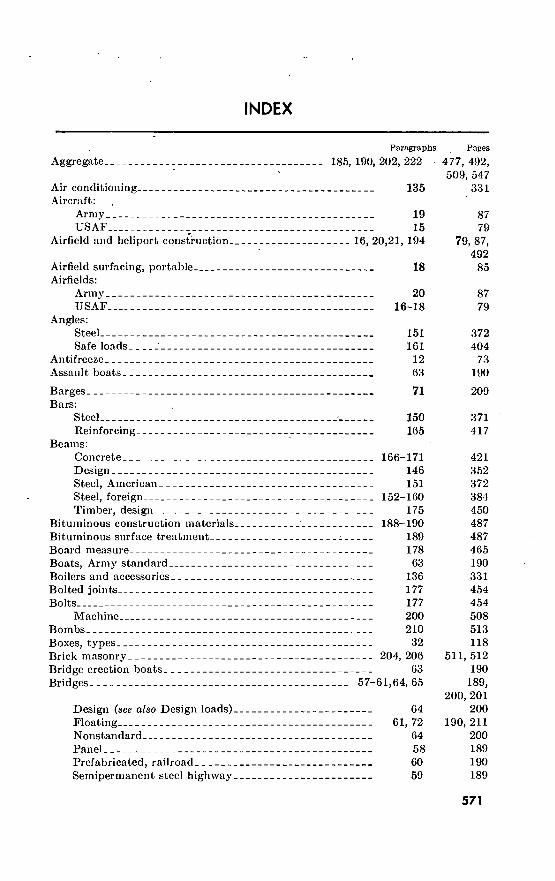
INDEX
Paragraphs Pages
Aggregate 185, 190, 202, 222
Air conditioning 135 Aircraft:
Army 19 USAF 15
Airfield and heliport construction 16, 20,21, 194
Airfield surfacing, portable 18 Airfields:
Army 20 USAF 16-18
Angles: Steel 151 Safe loads ' 161
Antifreeze 12 Assault boats 63
477, 492, 509, 547
331
87 79
79, 87, 492
85
87 79
372 404
73 190
Barges Bars:
Steel Reinforcing
Beams: Concrete Design Steel, American Steel, foreign Timber, design
Bituminous construction materials Bituminous surface treatment Board measure Boats, Army standard Boilers and accessories, Bolted joints Bolts
Machine Bombs Boxes, types Brick masonry Bridge erection boats Bridges
71
150 165
166-171 146 151
152-160 175
188-190 189 178 63
136 177 177 200 210
32 _ -, 204, 206
63 57-61,64, 65
Design (see also Design loads) 64 Floating 61, 72 Nonstandard 64 Panel 58 Prefabricated, railroad 60 Semipermanent steel highway 59
209
371 417
421 352 372 384 450 487 487 465 190 331 454 454 508 513 118
511, 512 190
189, 200, 201
200 190, 211
200 189 190 189
571
Paragraphs Pages
British weight markings 217 529 Building materials, properties (see also Materials, structural) 219 534
Cableways 66, 67 Calendar, 1956-75 225 Camouflage 48-51 Cesspools 104 Chains, metal 184 Channels, steel, American, characteristics 151 Chemical equipment, engineer units 8 Chests, engineer equipment 6 Circuit-breakers 131 Cleaning materials, types and uses 32 Coagulants for water 86 Cold storage 132 Columns, wood, design 176 Concrete 164-172,185-187 Concrete block masonry 205, 206 Concrete, reinforced 164-172 Concrete retaining walls 172 Connectors, timber 177 Construction:
Airfields and heliports 16, 20, 21 Bridges 64 Obstacles 45-47 Prisoner-of-war enclosures 36 Railroads 22, 24-27 Roads 54, 188-190, 194
Construction equipment, engineer 9 Conversion tables for units of measure 215, 216, 224
Corrugated sheet metal 180 Cover and shelter 39-44 Culverts 54 Cylinders, gas 31
Daylight, hours 227 Dead loads 140 Defensive frontages 38 Design :
Airfields and heliports 16, 20, 21 Bridges 64 Roads : 53
Design formulas (see also Structural design data) 146-148 Design, structural, data 139-177 Discharge and pressure data 80, 83, 84, 95
Distillation of water 77, 89
201 563 152 260 470 372
54 32
325 118 228 328 452
412, 477 512 412 437 454
79, 87 200 140 129 94
171, 487, 492
57 522,
529, 550
468
136 171 107
566 336 135
79, 87 200 169 352
. 336 217,
225, 254 216, 244
Electric lighting 129, 130 325 Electric power distribution 115, 131 267, 325 Electric power: foreign voltages and frequencies 116 267 Electric pole lines 127 297 Electric power systems, loads 121, 124 278, 281
572

Electrical equipment.
Paragraphs
122-125, 127, 131
Electrical layout for hospital 126 Engineer equipment:
Chests and sets 6 Motorized 9
• Other than motorized (see also Equipment, engineer) 6 Wire rope requirements 182
Engineer library reference sets 228 Engineer troop units 5 Equipment, engineer 6-10,
23, 48-51, 58-63, 66, 67, 88, 90, 132, 134, 136, 137, 182
Equivalents of measure 21 215, 216, 224
Explosives 208-211
Feed-water heaters. Fiberboard Filtration Floor loads Forms, concrete Fortification Frontages, defensive.
136 195 88 141 187 37-47 38
Fuels, motor ' 12, 13
Garbage. (See Refuse collection and disposal.) Gases 31
Densities 220 Generators :
Electric 123, Hot water Steam
Gravel (see also Aggregates) Piled volume computation
Gravel pits
Hangars Heavy equipment, engineer Heliports, Army Hollow tile masonry 205, 206 Hooks, metal 184 Hospital, electrical layout 126
Ice 41-43, 77 Ice concrete 43 Ice plants 134 Impact loads 144 Incinerators 112 Insulation, structural 195
124 136 137 202 222
54
17 9
21
Pages
279, 297, 325
297
32 57 32
469 566
4 32, 94,
152, 189, 201, 234, 245/ 328, 329, 331, 333,
469 522,
529, 550 513
331 492 234 339 478 135 135
73, 76
107 546
280, 281 331 333 509 547 171
85 57 87
512 470 297
139, 216 140 329 350 265 492
573

Paragraphs Pages
Lag screws 177, 199 454, 500 Library reference sets, engineer 228 566 Lighting, electric 129, 130 325 Live loads 141, 142 339, 349 Loads, design 139-145 336 Lubricants, motor 12, 13 73,, 76 Lumber, dressed:
Dimensions and properties 174 450 Measurement 178, 179 465
Magazines, ordnance 211 515 Manila rope 201 509 Masonite 195 492 Masonry 203-207 511 Materials, properties 219 534 Materials, structural (see also Structural design data) 178-207 465 Mathematical data and formulas 212-214 517 Medical equipment, engineer units 8 54 Messhalls, utilities • 138 333 Minefields ^ . 46 144 Mines - 46 144
American and foreign 210 513
Mortar 207 512 Motorized equipment, engineer units 9, 10 57, 72
Nails 177, 196 454, 499
Obstacles 45-47 140 Ordnance equipment, engineer units 8, 10, 30 54, 72,
107
Packaging and crating of materials 32 118 Paints, camouflaged 51 155 Piles, wood, safe loads 223 548 Pipe, steel:
Characteristics il 151 372 (As columns), Safe loads 161 404
Pipes: Flow 79,95 216,254 Sewer, sizes 100 257 Water, standard 92 247
Plates, steel, characteristics 150 371 Plumbing fixtures 94 253 Poles and pole lines, electric : 127 297 Pontoon equipment 68-74 207 Prefabricated buildings 29 107 Preservatives, types and uses 32 118 Pressure and discharge data 80, 83, 84, 95 217,
225, 254
Prisoner-of-war enclosures 33, 36 128, 129 Pumps:
Boiler feed 136 331 Standard 88 234
Quarries and quarrying 54 171 Quartermaster equipment, engineer units 8 54
574

Paragraphs
Radio equipment, engineer units 7 Rafts 62 Rail shipments of engineer equipment 23 Railroad bridges, prefabricated 60 Railroad data . 22-28 Railroad gages, foreign 28 Railroad mileages, foreign 28 Rails,-steel, characteristics 151 Reconaissance boats 63 Reference texts, engineer 228 Refrigerants, 2 133
■ Refrigeration - 132 Refuse collection and disposal 108-114 Reinforcing bars 165 Reinforcement, protection 165 Repair parts, engineer, identification 14 Retaining walls, concrete 172 Rigid frames, stresses 147 Riveted connections 162 Road signs 56 Roads:
Construction 54, 188-190, 194
Design 53 Drainage 54 Maintenance 55 Military 52-56
Roof live loads 142 Roofing materials 195, 196 Rope:
Manila 201 Wire 181-183
Pages
50 190 94
190 94 97 97
372 190 566 329 328 263 417 417
78 437 353 405 181
171, 487, 492 169 171 180 169 349
492, 499
509 468
Sand (see also Aggregates) 202 509 Sand and gravel, piled volume computation 222 547 Sanitary fills 111 264 Screws 177, 197, 199 454, 500 Septic tanks 102 259 Sets, engineer equipment 6 32 Sewer lines, sizes 100 257 Sewerage and sewage treatment 96-107 254 Sewers, maintenance 107 262 Shells, artillery 210 513 Shelter 39-44 136 Signal equipment engineer units 7, 8 50, 54 Signs, road 56 181 Slabs, concrete, design 167, 170 421, 435 Slump (concrete) 186 477 Snow 41, 42, 77 139, 140,
216 Soil classification 192 492 Soils 191-194 492 Spikes 177, 196 454, 499 Springs 77, 79 216
575

Paragraphs Pages
Staples Steel, structural Steel products. _
198 149-163 150-161, 165, 180-184
Steel shapes, characteristics 150-161 Stone masonry 203, 206 Storm boats 63 Stream crossing equipment 57-65 Streams, water supply from 77, 79 Stringers, bridge 65 Structural design data 139-177 Structural steel 149-163 Surge tanks 136
500 368
371, 417, 468 371
511,'512 190 189 216
'201 336 368 331
Tank capacities 85 228 Tanks, cylindrical, contents 221 546 Teams, engineer 5 4 Ties, railroad 24 94 Timber and lumber 173-177 437 Timber connectors 177 454 Timber, working stresses 173 437 Time, elapsed, between twro dates 226 564 Tramways 66 201 Transformers, electric 122 279 Troop units, engineer 5 4 Trusses:
Design 140 336 Stresses.., . , 148 362
USAF airfields and aircraft 15-18 79 Units of measurement, foreign 217, 218 529, 530 Utilities 75-138 215
Vehicles with engineer troops 10, 11 Volume and capacity equivalents 82
Wallboard 195 Warehouses, refrigerated 132 Water-cement ratios 164 Water:
Coagulants 86 Consumption 78 Distillation 77, 89 Flow 79-81, 83, 84, 93, 95
Purification and treatment 86, 88, 90
Sources 77 Water pressures 92 Water purification equipment 88-90 Water supply and distribution 75-95
Responsibilities 76 Weapons of engineer units 30 Weights and measures, foreign 217, 218
Conversion factors 215, 216, 224
72, 73 225
492 328 412
228 216
216, 244 216, 225, 248, 254
228, 234, 245 216 247 234 215 215 107
529, 530 522, 529,
550
576

en als
ictric, characteristics
WiÄ&ntanglements Wire^-ope Wood framing, connections-.
Paragraphs 141, 150, 160 180, 181, 184, 185, 196, 201, 202, 206
163 77,79 143 125, 127, 128, 131
47 181-183 177
Pages
339, 371, 468, 470, 477, 499, 509, 512
406 216 350
285, 297, 312, 325
150 468 454
[AG 461 (24 Jun 59)]
BY ORDER OF THE SECRETARIES OF THE ARMY AND THE AIR FORCE :
- • L. L. LEMNITZEE, General, United States Army,
OFFICIAL: Chief of Staff. K. Y. LEE,
Major General, United States Army, The Adjutant General.
THOMAS D. WHITE, OFFICIAL : Chief of Staff, United States Air Force.
J. L. TAKE, Colonel, United States Air Force,
Director of Administrative Services.
577

3000015595
DISTRIBUTION:
Active Army:
DCSLOG (2) CNGB (1) CofEngrs (50) Engr RD Lab (10) ATB (2) USA Arty Bd (2) USA Armor Bd (2) USA Inf Bd (2) USA AD Bd (2) USA Abn & Elct Bd (2) USA Avn Bd (2) US ARADCOM (5) US ARADCOM Rgn (5) OS Maj Comd (45) except USAR
SETAE (50) OS Base Comd (10) Log Comd GO) MDW (15) Armies (45) except First US.
Army (47) Corps (10) Div (10) except 6th Armd Div
(15) Engr Bde (5) Engr Gp (5) Engr Bn (3) Engr Co (3) US MA (50) Svc Colleges (50) Br Svc Sch (5) except
Engr Sch (515) USAAMS (50) US ARADSCH (7)
PMST Sr Div Units (5)
PMST Jr Div Unitl PMST Mil Sch Div| GENDEP (5) excjj
GENDEP (7) Engr Sec GENDEP^ Depots (5) except En^f AH (1) Ports of Emb (OS) (2) Trans Terminal Comd.(2) Army Terminal (2) OS Sup Agcy (5) Engr Maint Cen (5) Arsenals (5) Eld Maint Shops (2) Engr Sup Con Ofc (St Louis' (2) USAREUR, Engr Proc Cen (2) USAREUR Engr Sup Con Ofc (2y USAREUR CommZ (2) Div Engr (5). Engr Dist (5) except
Savannah Dist Engr (10) Washington Dist Engr (10)
Mil Dist (3) USA Corps (Res) (3) Sector Comd USA Corps (Res) (3) MAAG (2) JÄTHM AT (10) Yuma Test Sta (5) JBUSMC (10) Eld Comd Def Atomic Spt Agcy
(2) Units organized under following
TOE: 5-500 (AA through AC) (2)
NG: State AG (3) ; units—same as Active Army except allowance is one copy to each unit.
USAR: Units—same as Active Army except allowance is one copy to each unit.
For explanation of abbreviations used, see AR 320-50.
578 U.S.'GOVERNMENT PRINT!NG .OFFICE : 1960


PE
NT
AG
ON L
IBR
AR
Y